Embed Size (px)
Citation preview
Leader in Level Measurement
Technical Assistance: 1-800-527-6297 Outside North America: +1-215-674-1234
Installation andOperating Instructions
DR7100 SeriesGuided Radar (TDR) Level Instrument
forTwo-Wire Control Systems
U.S. and Canada: 1-800-553-909224-Hour Service: 1-800-527-6297International: +1 215-674-1234Fax: +1 215-674-2731E-mail: [email protected] Website: www.drexelbrook.com

AMETEK Drexelbrook makes no warranty of any kind with regard to the material contained in this manual, including, but not limited to, implied warranties or fitness for a particular purpose. Drexelbrook shall not be liable for errors contained herein or for incidental or consequential damages in connection with the performance or use of material.
Copyright 2007 AMETEK Drexelbrook
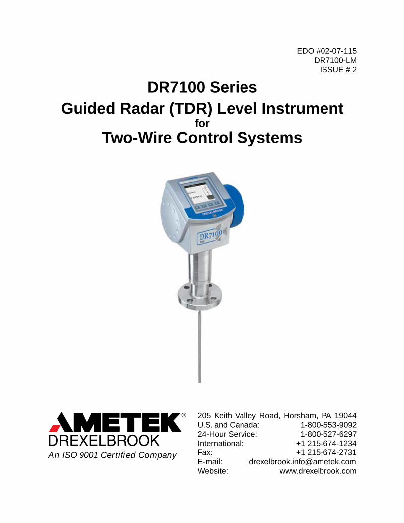
DR7100 SeriesGuided Radar (TDR) Level Instrument
forTwo-Wire Control Systems
EDO #02-07-115 DR7100-LM
ISSUE # 2
205 Keith Valley Road, Horsham, PA 19044 U.S. and Canada: 1-800-553-909224-Hour Service: 1-800-527-6297International: +1 215-674-1234Fax: +1 215-674-2731E-mail: [email protected] Website: www.drexelbrook.com
An ISO 9001 Certified Company

Contents
Contents Quick Start ................................................................................................................... QS1
0.0 Introduction ...................................................................................................... 1 0.1 Legal Matters ..................................................................................................... 2 0.2 Warranty ............................................................................................................. 3 0.3 Standards and Approvals ................................................................................... 4 0.4 Principal Meter Components and Options ......................................................... 5 0.5 Nameplates ........................................................................................................ 6 0.6 Items Supplied ................................................................................................... 7 0.7 Storage and Handling ........................................................................................ 8 1.0 Location ............................................................................................................ 9 1.1 All Applications ................................................................................................... 9 1.2 Installation relative to other tank components .................................................. 16 1.2.2 Liquid applications ........................................................................................... 19 1.2.3 Solid Applications ............................................................................................. 24 1.3 Typical installations ......................................................................................... 26 1.4 Other important information ............................................................................. 39
2.0 Electrical connection ..................................................................................... 41 2.1 Wiring ............................................................................................................... 41 2.1.2 Wiring Procedure ............................................................................................. 42 2.2 Power supply .................................................................................................... 46
3.0 Commissioning .............................................................................................. 53 3.1 Power-on and start-up ..................................................................................... 53
4.0 Operation ........................................................................................................ 55 4.1 Operating concept ............................................................................................ 55 4.1.2 Display screen ................................................................................................. 56 4.1.3 Normal mode ................................................................................................... 58 4.1.4 Normal mode hot keys ..................................................................................... 62 4.1.5 Program mode ................................................................................................. 63 4.1.6 Program mode hot keys ................................................................................... 67 4.2 Setup ................................................................................................................ 68 4.2.1 Device display .................................................................................................. 68 4.2.2 Quick setup: setup modes ................................................................................ 68 4.2.3 Summary of menu items (device display Wizard) ............................................ 79 4.2.4 Advanced setup: further notes ......................................................................... 93 4.3 Error messages and troubleshooting (device display Wizard) ....................... 110 5.0 Functional checks ........................................................................................ 117
6.0 Service and maintenance ............................................................................ 119 6.1 General notes ................................................................................................ 119 6.2 Signal converter replacement Procedure ....................................................... 120
7.0 Technical data .............................................................................................. 121 7.1.1 Technical data ................................................................................................ 121 7.1.2 Blocking distance ........................................................................................... 125 7.1.3 Hazardous areas ............................................................................................ 126 7.2 Dimensions and weights ................................................................................ 127
8.0 Measuring principle ..................................................................................... 129 8.1 General principle ............................................................................................ 129 8.2 Measuring modes .......................................................................................... 130
9.0 Approvals ...................................................................................................... 133
10.0 Factory Assistance ...................................................................................... 135
11.0 Control Drawings ......................................................................................... 137
Appendix A: ....................................................................................................................A1 A-1 Mechanical Installation .....................................................................................A3 A-1.1 Precautions ......................................................................................................A3 A-1.2 Operating conditions ........................................................................................A3 A-1.1.2 Electrostatic Discharge ....................................................................................A3 A-1.2 Operating conditions (Continued) ....................................................................A4 A-2 Electrical connection ........................................................................................A5 A-2.1 General notes ..................................................................................................A5 A-2.2 The terminal compartment cover .....................................................................A5 A-2.2.1 Opening the cover ............................................................................................A5 A-2.2.2 Closing the cover .............................................................................................A5 A-2.3 EEx i equipment ...............................................................................................A6 A-2.3.1 Wiring ...............................................................................................................A6 A-2.3.2 Supply voltage .................................................................................................A6 A-2.4 EEx d [ia] equipment ........................................................................................A7 A-2.4.1 General notes ..................................................................................................A7 A-2.4.2 Wiring ...............................................................................................................A7 A-2.4.3 Supply voltage .................................................................................................A7 A-2.4.4 Power supply ....................................................................................................A8 A-3 Commissioning ..............................................................................................A10 A-4 Service and maintenance ..............................................................................A10 A-5 Examination Certificate ..................................................................................A11
Quick Start
QS1
Quick Start
DR7100 Radar Level Measurement SystemMeasurement of distance, level and volume of liquids, slurries and solids• Easy installation• Wizard driven• Service and maintenance-free
GeneralFor in-depth information please consult the hand-book, data sheet, special manuals and certificates supplied.
Installation, assembly, commissioning and servicing must only be undertaken by trained personnel. Maintenance which is considered relevant to safety in the sense of explosion protection must only be carried out by the manufacturer, his agents or under the supervision of experts.
For use in hazardous areas, special codes and regulations are applicable, which are supplied in a separate document that describes all hazardous area relevant information.
Responsibility as to suitability and intended use of this device rests solely with the user. The supplier does not accept any liability resulting from misuse by the customer. Improper installation and operation may lead to loss of warranty. In addition, the “General conditions of sale”, found on the back of the invoice and forming the basis of the purchasing contract, are applicable.
If you need to return the device to the manufacturer or supplier, please complete the form in Section 9.0 and attach to the device. Drexelbrook regrets that it cannot repair or check your device unless accompanied by this completed form.
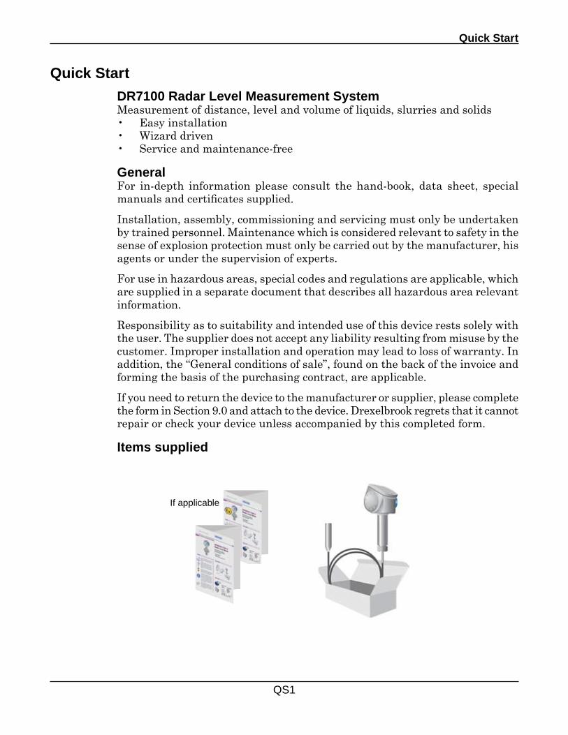
Items supplied
If applicable
D7100 Series - TDR Level Instrument - User's Manual
QS2
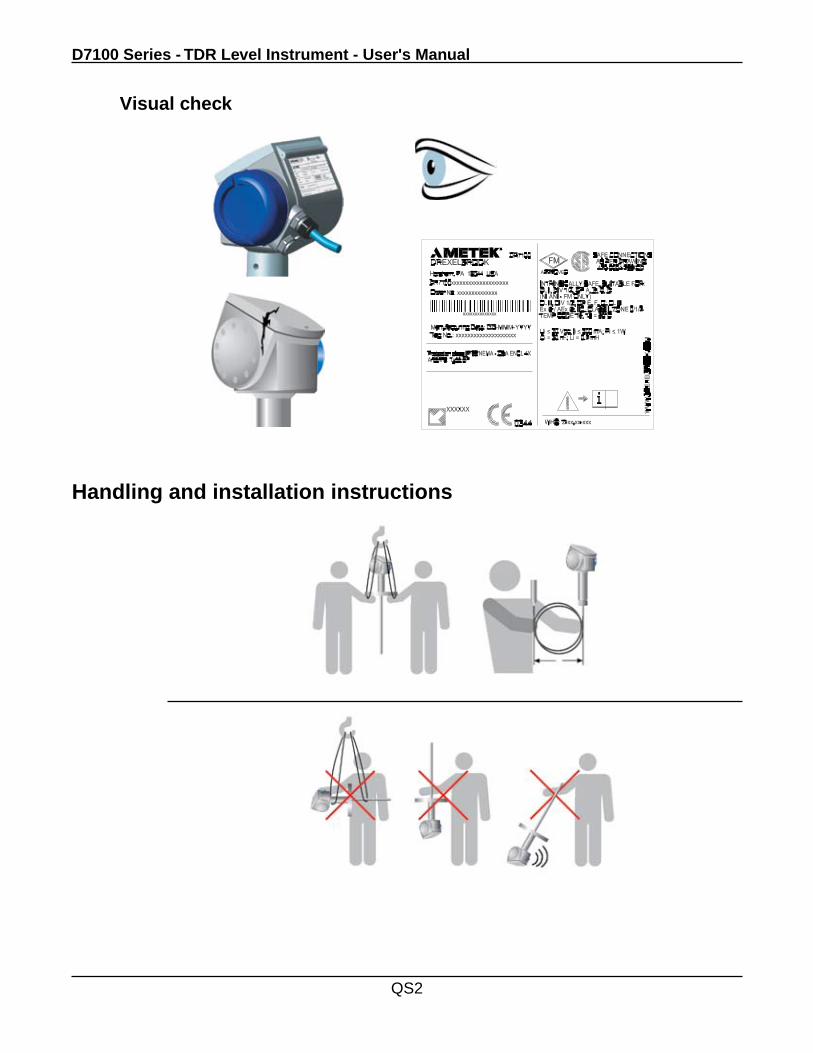
Handling and installation instructions
Visual check
Quick Start
QS3
h
Handling and installation instructions
h _> ød
h > ød
ød
+80°C / +175°F-40°C / -40°F
max. 200°C / 392°F
min. -40°C / -40°F Viton
min. - 20°C / -5°F Kalrez 6375
Antenna must not touch nozzel
D7100 Series - TDR Level Instrument - User's Manual
QS4
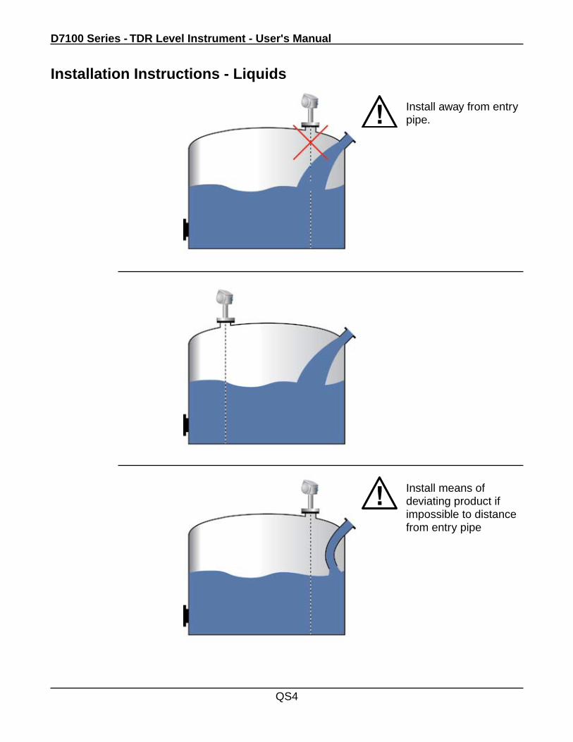
Installation Instructions - Liquids
Install away from entry pipe.
Install means of deviating product if impossible to distance from entry pipe
Quick Start
QS5
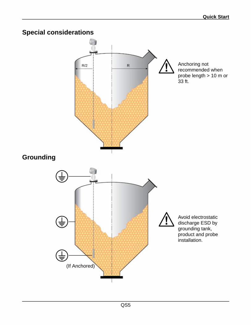
Special considerations
R/2
Grounding
Avoid electrostatic discharge ESD by grounding tank, product and probe installation.
Anchoring not recommended when probe length > 10 m or 33 ft.
(If Anchored)
R
D7100 Series - TDR Level Instrument - User's Manual
QS6
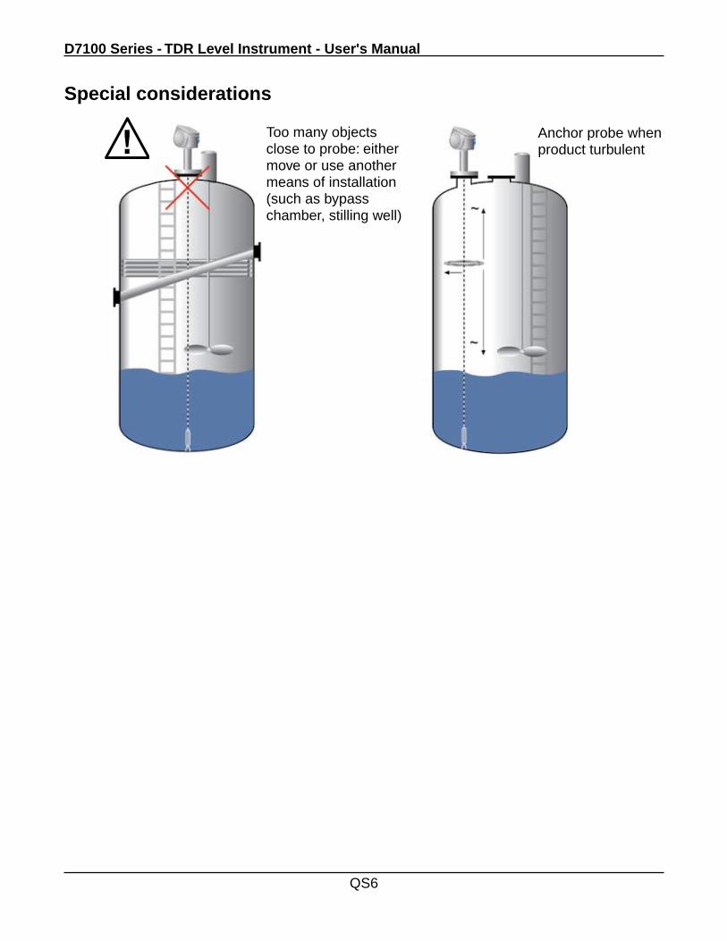
Special considerations
Too many objects close to probe: either move or use another means of installation (such as bypass chamber, stilling well)
Anchor probe when product turbulent
Quick Start
QS7
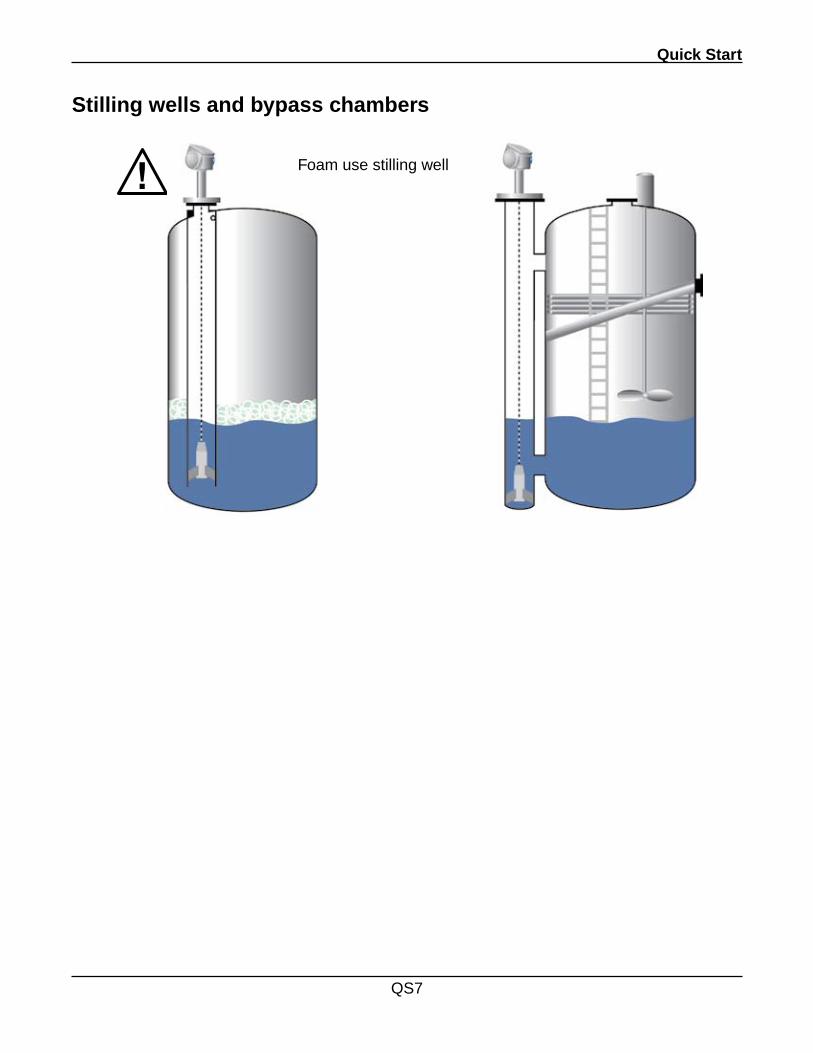
Stilling wells and bypass chambers
Foam use stilling well
D7100 Series - TDR Level Instrument - User's Manual
QS8
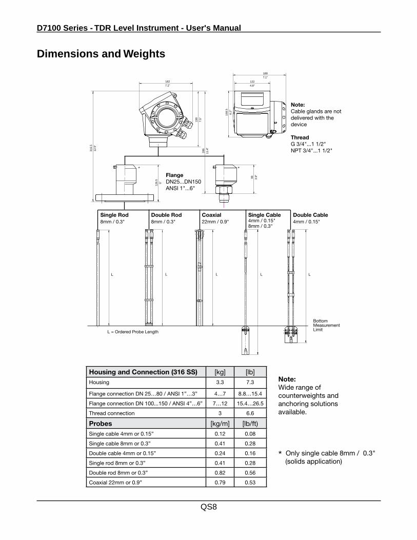
Dimensions and Weights
Housing and Connection (316 SS) [kg] [lb]Housing 3.3 7.3
Flange connection DN 25…80 / ANSI 1”…3” 4…7 8.8…15.4
Flange connection DN 100...150 / ANSI 4”…6” 7…12 15.4…26.5
Thread connection 3 6.6
Probes [kg/m] [lb/ft)Single cable 4mm or 0.15” 0.12 0.08
Single cable 8mm or 0.3” 0.41 0.28
Double cable 4mm or 0.15” 0.24 0.16
Single rod 8mm or 0.3” 0.41 0.28
Double rod 8mm or 0.3” 0.82 0.56
Coaxial 22mm or 0.9” 0.79 0.53
190
7.5"
126.
55"
289
11.4
"
316.
512
.5"
1827.2"
158.
56.
2"
1807.1"
1224.8"
99 3.9"
LL L L L
Bottom Measurement LimitL = Ordered Probe Length
Note:Cable glands are not delivered with the device
ThreadG 3/4"...1 1/2"NPT 3/4"...1 1/2"
Single Rod8mm / 0.3"
Double Rod8mm / 0.3"
Coaxial22mm / 0.9"
Single Cable4mm / 0.15"8mm / 0.3"
Double Cable4mm / 0.15"
FlangeDN25...DN150ANSI 1"...6"
Note:Wide range of counterweights and anchoring solutions available.
* Only single cable 8mm / 0.3" (solids application)
Quick Start
QS9
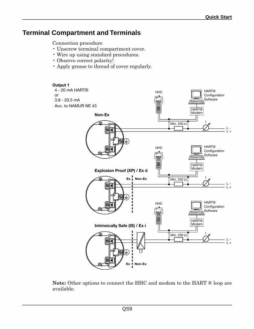
Terminal Compartment and Terminals
Output 1 4 - 20 mA HART® or 3.8 - 20.5 mA Acc. to NAMUR NE 43
HART® Configuration Software
HART® Modem
Min. 250 Ω L -L +
I
HHC
Non-Ex
HART® Configuration Software
HART® Modem
Min. 250 Ω L -L +
I
HHC
Explosion Proof (XP) / Ex d
Ex Non-Ex
HART® Configuration Software
HART® Modem
Min. 250 Ω L -L +
I
HHC
Intrinsically Safe (IS) / Ex i
Ex Non-Ex
Connection procedure• Unscrew terminal compartment cover.• Wire up using standard procedures.• Observe correct polarity!• Apply grease to thread of cover regularly.
Note: Other options to connect the HHC and modem to the HART ® loop are available.
D7100 Series - TDR Level Instrument - User's Manual
QS10
Technical data extract
InputFunction Time Domain Reflectometry (TDR)Parameter Level, distance, volume and / or interfaceMax. measuring range Double rod 8mm / 0.3” 4m / 13ft Single rod 8mm / 0.3” 4m / 13ft Coaxial 22mm / 0.9” 6m / 20ft Double cable 4mm / 0.15” 35m / 115ft Single cable 4mm / 0.15” 35m / 115ft Single cable 8mm / 0.3” 35m / 115ft
Output SignalOutput signal 1 4 - 20mA HART® or 3.8 - 20.5 mA acc. to NAMUR NE 43Output signal 2 4 - 20mA or 3.8 - 20.5 mA (Optional) acc. to NAMUR NE 43
Accuracy 0.05% (rel. 20 mA; 20°C / 68°F)Resolution ±2 µATemperature Drift Typically 50 ppm/KError Signal High: 22 mA; Low: 3.6 mA acc. to NAMUR NE 43Max. Load 350 ohm
Measuring Accuracy - Reference conditions acc. to IEC770Temperature +20°C ±5°C / +68°F ±9°FPressure 1013 mbar abs. ±20 mbar 14.69 psig ±0.29 psigRelative Humidity 60% ±15%Resolution 1 mm / 0.04 “Accuracy In Direct Mode Liquids ±3 mm / ±0.12” whenL<10m/33ft; ±0.03%ofmeasureddistance, whenL>10m/33ft
Powders ±20 mm / ±0.8”
Interface ±10 mm (εr Constant)
Application ConditionsAmbient Temp. -40…+80°C / -40…+175°F; EEx i: -40…+60°C / -40…+140°FStorage Temp. -40…+85°C / -40…+185°FFlange Temp. -40…+200°C / -40…+392°F (Ex: refer to relevant device spec.)Shock Resistance 100°C/minProcess Conditions Operating Pressure 1…40 bar / -14.5…580 psig; subject to process connection and temp.Dielectric Constant >_ 1.4 Coaxial Probes >_ 1.6 For single and Twin ProbesVibration Resistance IEC 68-2-6 and prEN 50178 (10...57Hz: 0.075 mm / 57...150 Hz: 1 g)Protection Category IP 66/67 equiv. to NEMA 6-6X
Mechanical DataHousing AluminiumWetted Parts Rod Stainless steel (1.4404 / 316L); Hastelloy C-22 (2.4602) Coaxial Stainless steel (1.4404 / 316L); Hastelloy C-22 (2.4602) Cable (4mm /0.15") Stainless steel (1.4401 / 316); Hastelloy C-22 (2.4602)Process Fitting Stainless steel (1.4404 / 316L); Hastelloy C-22 (2.4602)Gaskets Viton (-40…+150°C / -40…+300°F); Kalrez 6375 (-20…+150°C / -5 …+300°F)Process Connection Thread G 3/4"...1 1/2"; NPT 3/4"...1 1/2"Flange DN 25…DN 150 (PN 40 / PN 16); 1”…8” (150 lb / 300 lb); 10 K (40…100A)
Electrical Connection - 2-Wire Power Supply Terminals Output 1 Non-Ex/ EEx i 24 VDC (14 … 30 VDC) EEx d 24 V DC (20 … 36 VDC)Terminals Output 2 Non-Ex/ EEx i / EEx d 24 VDC (10 … 30 VDC)Cable Entry Terminals M20x1.5; 1/2 NPT; G 1/2" 0.5…1.5 mm²
Human machine interfaceDisplay 9 lines, 160x160 pixels in 8-step greyscale with 4-button keypadOperating Languages English, German, French, Italian, Spanish, Portugese, Japanese, Chinese (Mandarin), Russian
Approvals ATEX ATEX II G D EEx ia IIC T3...T6 ATEX II 1/2 G D EEx d [ia] IIC T6...T3FM IS class I Div. 1 Gr. A...G; XP class I Div. 1 Gr. A…GCSA CL. 1, Zone 0, Ex ia, II C CL. 1, Zone 1, Ex d [ia], II C
Quick Start
QS11
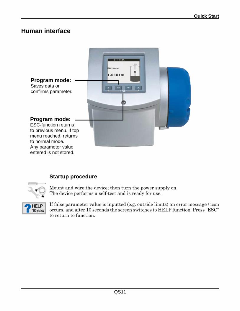
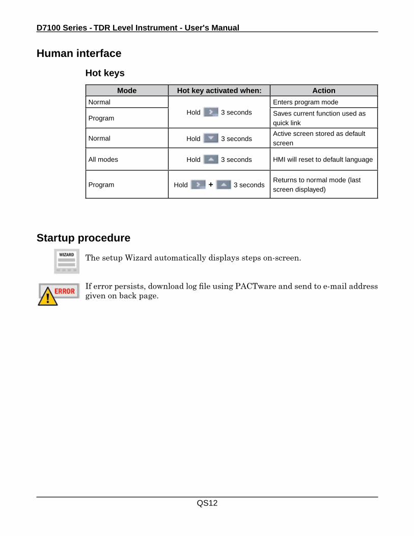
Human interface
Program mode:Saves data or confirms parameter.
Program mode:ESC-function returns to previous menu. If top menu reached, returns to normal mode.Any parameter value entered is not stored.
ESC
Startup procedure
Mount and wire the device; then turn the power supply on.The device performs a self-test and is ready for use.
If false parameter value is inputted (e.g. outside limits) an error message / icon occurs, and after 10 seconds the screen switches to HELP function. Press “ESC” to return to function.
D7100 Series - TDR Level Instrument - User's Manual
QS12
Mode Hot key activated when: Action
Normal
Hold 3 seconds
Enters program mode
ProgramSaves current function used as quick link
Normal Hold 3 secondsActive screen stored as default screen
All modes Hold 3 seconds HMI will reset to default language
Program Hold + 3 secondsReturns to normal mode (last screen displayed)
Human interface
Startup procedure
The setup Wizard automatically displays steps on-screen.
If error persists, download log file using PACTware and send to e-mail address given on back page.
Hot keys
Quick Start
QS13
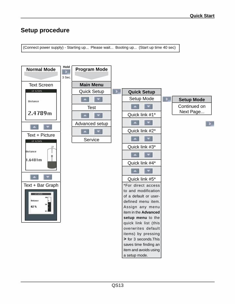
(Connect power supply) - Starting up... Please wait... Booting up... (Start up time 40 sec)
Setup procedure
Normal Mode
Text Screen
Text + Picture
Text + Bar Graph
Program Mode
Main MenuQuick Setup
Test
Advanced setup
Service
3 Sec.
Hold
Quick SetupSetup Mode
Quick link #1*
Quick link #2*
Quick link #3*
Quick link #4*
Quick link #5*
*For direct access to and modification of a default or user-defined menu item. Assign any menu item in the Advanced setup menu to the quick link list (this overwrites default items) by pressing > for 3 seconds.This saves time finding an item and avoids using a setup mode.
Setup ModeContinued on Next Page...
D7100 Series - TDR Level Instrument - User's Manual
QS14
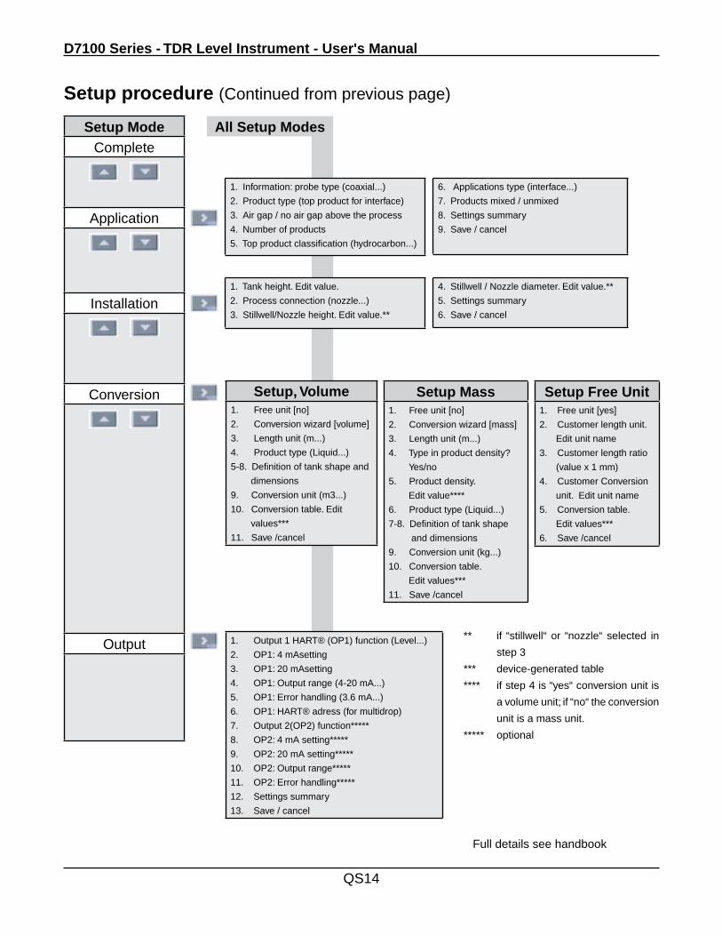
Setup ModeComplete
Application
Installation
Conversion
Output
Full details see handbook
Setup procedure (Continued from previous page)
All Setup Modes
1. Information: probe type (coaxial...)
2. Product type (top product for interface)
3. Air gap / no air gap above the process
4. Number of products
5. Top product classification (hydrocarbon...)
Setup, Volume1. Free unit [no]
2. Conversion wizard [volume]
3. Length unit (m...)
4. Product type (Liquid...)
5-8. Definition of tank shape and
dimensions
9. Conversion unit (m3...)
10. Conversion table. Edit
values***
11. Save /cancel
1. Output 1 HART® (OP1) function (Level...)
2. OP1: 4 mAsetting
3. OP1: 20 mAsetting
4. OP1: Output range (4-20 mA...)
5. OP1: Error handling (3.6 mA...)
6. OP1: HART® adress (for multidrop)
7. Output 2(OP2) function*****
8. OP2: 4 mA setting*****
9. OP2: 20 mA setting*****
10. OP2: Output range*****
11. OP2: Error handling*****
12. Settings summary
13. Save / cancel
Setup Mass1. Free unit [no]
2. Conversion wizard [mass]
3. Length unit (m...)
4. Type in product density?
Yes/no
5. Product density.
Edit value****
6. Product type (Liquid...)
7-8. Definition of tank shape
and dimensions
9. Conversion unit (kg...)
10. Conversion table.
Edit values***
11. Save /cancel
Setup Free Unit1. Free unit [yes]
2. Customer length unit.
Edit unit name
3. Customer length ratio
(value x 1 mm)
4. Customer Conversion
unit. Edit unit name
5. Conversion table.
Edit values***
6. Save /cancel
** if “stillwell“ or “nozzle“ selected in
step 3
*** device-generated table
**** if step 4 is “yes“ conversion unit is
a volume unit; if “no“ the conversion
unit is a mass unit.
***** optional
6. Applications type (interface...)
7. Products mixed / unmixed
8. Settings summary
9. Save / cancel
1. Tank height. Edit value.
2. Process connection (nozzle...)
3. Stillwell/Nozzle height. Edit value.**
4. Stillwell / Nozzle diameter. Edit value.**
5. Settings summary
6. Save / cancel


Section 0
Introduction
1
0.0 Introduction
The DR7100 level gauge is designed solely for measuring the distance, level, volume and reflection of liquid, paste, slurry, and solid materials. The DR7100 level gauge does not form part of an overfill protection system. Special codes and regulations apply to its use in hazardous areas. Responsibility as to suitability and intended use of these level gauges rests solely with the user. Improper installation and operation of our level gauges may lead to loss of warranty.
The DR7100 is a new-generation level meter with a wizard-driven setup, fully-potted electronic subassemblies, an online help functions.
It is provided with a pictorial quick setup. You will not normally need this Handbook to install, set up and operate the device.
All menu items have an on-screen help function that is activated 15 seconds after the last input.
In the unlikely event of a failure, error icons appear on-screen. Clicking on the error icon in the PACTware device tool manager software or by looking in the error record menu item in program mode using the device screen wizard displays an error description, which normally is sufficient to rectify the problem. Only in severe cases will you need to consult the error records.
General Advice on Safety
• Visually inspect the equipment before installation to check that it has not been damaged in transit.
• Follow all instructions carefully to make sure that you install the device correctly
• Observe special conditions for installations requiring approved equipment
• Check that the flange, gasket and antenna materials are compatible with the product in the tank.
• Check that that the information on the device nameplate conforms to the on-site data
• Wire according to local rules and regulations
• Remove the device from the installation before servicing, except for replacement of the housing as described in section 6.2.
D7100 Series - TDR Level Instrument - User's Manual
2
0.1 Legal Matters
Authorised Personnel
Installation, assembly, commissioning and servicing must only be undertaken by Drexelbrook-trained personnel.Maintenance which is considered relevant to safety in the sense of explosion protection must only be carried out by the manufacturer, his agents or under the supervision of experts.
Liability
Responsibility as to suitability and intended use of these devices rests solely with the user. Improper installation and operation may lead to loss of warranty. In addition, Drexelbrook's General Conditions of Sale and Delivery, found on the back of the invoice and forming the basis of the purchasing contract, are applicable.
Special codes and regulations apply to its use in hazardous areas.
General Limitation on Liability
Unless otherwise expressly set forth in the Standard Terms and Conditions of Sale and Delivery, the Seller is only liable for damages, whatever their legal basis is, in case they are based on wilful action or gross negligence.This limitation on liability does not apply in the event the Buyer raises claims relating to personal injury or damages to property according to the product liability law based on a defect of the delivered goods.Any advice given by the Seller, in particular regarding the application of the delivered goods, shall only commit the Seller if given or confirmed in writing.
Returning the Device
If you need to return the level gauge to the manufacturer or supplier, please read to the instructions and complete the form in Section 9.0.
Introduction
3
0.2 Warranty
1. The Buyer shall examine the goods immediately after receipt with reasonable care; defects discovered shall be reported to the Seller within a preclusive period of 2 weeks in writing. Not recognizable defects shall be reported in writing to the Seller within 2 weeks after discovery.
2. In case of a justified immediate notification of defects, a warranty will be granted either by repairing the goods (rectification of defects) or replacement of default parts (subsequent delivery). Instead the Seller shall also be entitled to compensate the decrease in value when obeying the interest of the Buyer appropriately.
3. In case the Seller does not comply to rectify defects or to replace defective parts or the rectification or replacement fail, the Buyer shall be entitled to reduce the remuneration or, at his option, to rescind the contract.
4. As regards spare parts, parts being subject to wear and tear or parts being designated to become a part of or to be converted into other products, the Buyer is committed to examine such parts and give notification of defects within the time period set forth in paragraph 1. With regard to defects which could have been noticed before installation or conversion, any warranty claims are excluded after installation and conversion.
5. In case the Buyer requests examination of the delivered goods by the Seller and alleges a defect for which the Seller would be responsible according to paragraph 2 above, the Buyer shall be committed to bear the associated costs in case it turns out that the delivered goods are free from such defect.
6. Other or further claims of the Buyer based on defects including claims for damages, also with respect to consequential damages, are excluded. In case of non-compliance with a guarantee, which has to be designated and confirmed in the order confirmation as guarantee, claims for damages can only be enforced, if it was intended that the guarantee given to the Buyer should apply precisely to damage of the kind that has occurred.
7. The Seller’s liability is expired, if the goods delivered have been dismantled by a third party or altered by the incorporation of parts produced elsewhere and the cause of the damages is connected with such alterations. The Seller’s liability is also expired, if the Buyer does not duly observe the Seller’s instruction for handling the goods (installation & operation instructions).
8. Seller warrants that for a period of 12 months from start-up or 18 months after passing the risk, whichever comes first, under normal use and service its products will function in accord with the current product specifications if installed and operated in accordance with the accompanying installation manuals; but the Buyer is solely responsible for determining the suitability of the products for the Buyer’s use.
D7100 Series - TDR Level Instrument - User's Manual
4
0.3 Standards and Approvals
Standards
All versions of the device conform to European Union electromagnetic compatibility (89/336/CEE) and low voltage equipment (73/23/CE) Directives and Standards that allow use of the CE mark.
These and other relevant standards are listed in Standards.
Approvals
Versions equipped with the necessary options are suitable for use in hazardous areas meeting either European or American-Canadian approval requirements.
These are:
• ATEX (European) -approval• Joint FM and CSA (American-Canadian) -approval
Introduction
5
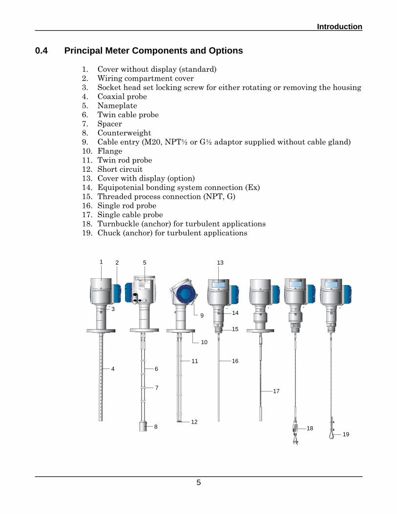
0.4 Principal Meter Components and Options
1. Cover without display (standard)2. Wiring compartment cover3. Socket head set locking screw for either rotating or removing the housing4. Coaxial probe5. Nameplate6. Twin cable probe7. Spacer8. Counterweight9. Cable entry (M20, NPT½ or G½ adaptor supplied without cable gland)10. Flange11. Twin rod probe12. Short circuit13. Cover with display (option)14. Equipotenial bonding system connection (Ex)15. Threaded process connection (NPT, G)16. Single rod probe17. Single cable probe18. Turnbuckle (anchor) for turbulent applications19. Chuck (anchor) for turbulent applications
KROHNE SASF-26103 Romans
OPTIFLEX 1300 CVF7100020020030010000000Manufacturing date 04/2004Order No. 144 123456 010
Tag No. INTERKAMA SAMPLE
Protection class IP 66/67
KEMA 04 ATEX xxxx XII 1G/D or II 1/2 G/Dor II 2 G/DEEx ia IIC T6 ... T1
Ui < 30 V Ci = 30 nFIi < 300 mA Li = 0.2 mHPi < 1 W�
0344 WHG: Z-xx.xx-xxx
1
4
8
16
5
11
9
12
14
1918
17
6
7
10
15
132
3
D7100 Series - TDR Level Instrument - User's Manual
6
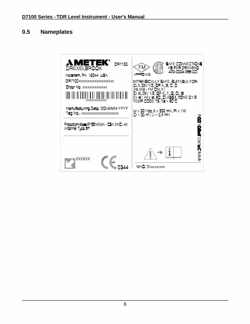
0.5 Nameplates
Introduction
7
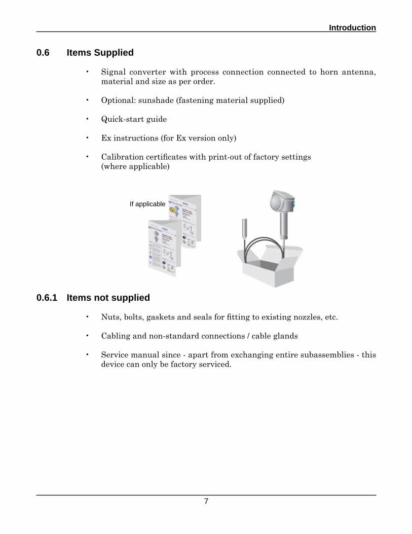
0.6 Items Supplied
• Signal converter with process connection connected to horn antenna, material and size as per order.
• Optional: sunshade (fastening material supplied)
• Quick-start guide
• Ex instructions (for Ex version only)
• Calibration certificates with print-out of factory settings (where applicable)
0.6.1 Items not supplied
• Nuts, bolts, gaskets and seals for fitting to existing nozzles, etc.
• Cabling and non-standard connections / cable glands
• Service manual since - apart from exchanging entire subassemblies - this device can only be factory serviced.
If applicable
D7100 Series - TDR Level Instrument - User's Manual
8
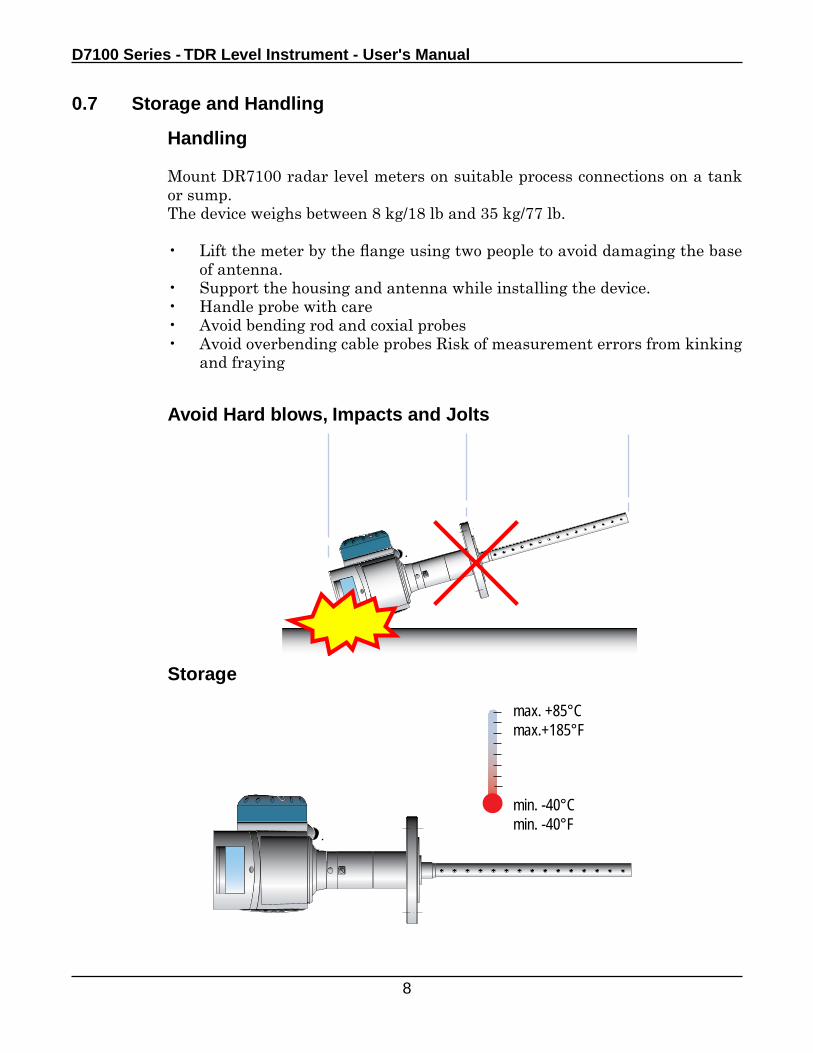
0.7 Storage and Handling
Handling
Mount DR7100 radar level meters on suitable process connections on a tank or sump.The device weighs between 8 kg/18 lb and 35 kg/77 lb.
• Lift the meter by the flange using two people to avoid damaging the base of antenna.
• Support the housing and antenna while installing the device.• Handle probe with care• Avoid bending rod and coxial probes• Avoid overbending cable probes Risk of measurement errors from kinking
and fraying
Avoid Hard blows, Impacts and Jolts
Storage
max. +85°Cmax.+185°F
min. -40°Cmin. -40°F
Location
9
1.0 Location
1.1 All Applications General Notes
This section covers positioning the process connection and installing the device.
Mount the DR7100 gauge on a suitable process connection on a tank or sump.
Check the following:
• Nozzle position in relation to the tank walls, product entry points and other objects inside the tanks.
This free space around the probe will depend on probe type refered to later on in this section.
• Installation adapted to the application
For further information on applications, refer to:
Section 1.2.2 Location - Liquid ApplicationsSection 1.2.3 Location - Solid ApplicationsSection 1.3 Typical - Installations
Hazardous areas
Refer to Appendix A.
D7100 Series - TDR Level Instrument - User's Manual
10
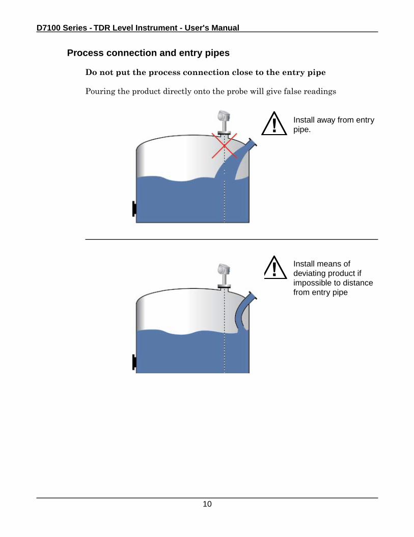
Process connection and entry pipes
Do not put the process connection close to the entry pipe
Pouring the product directly onto the probe will give false readings
Install away from entry pipe.
Install means of deviating product if impossible to distance from entry pipe
Location
11
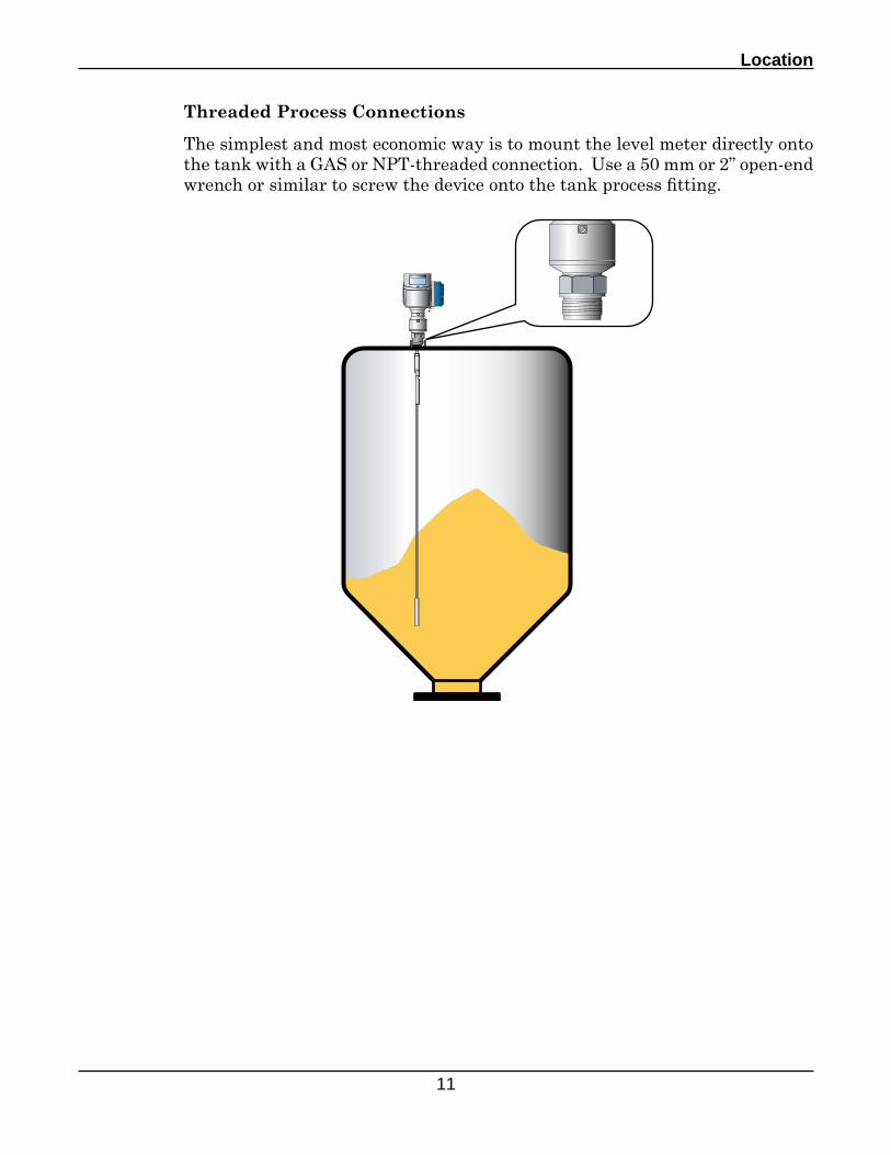
Threaded Process Connections
The simplest and most economic way is to mount the level meter directly onto the tank with a GAS or NPT-threaded connection. Use a 50 mm or 2” open-end wrench or similar to screw the device onto the tank process fitting.
D7100 Series - TDR Level Instrument - User's Manual
12
h
Ød
h > Ødh < Ød
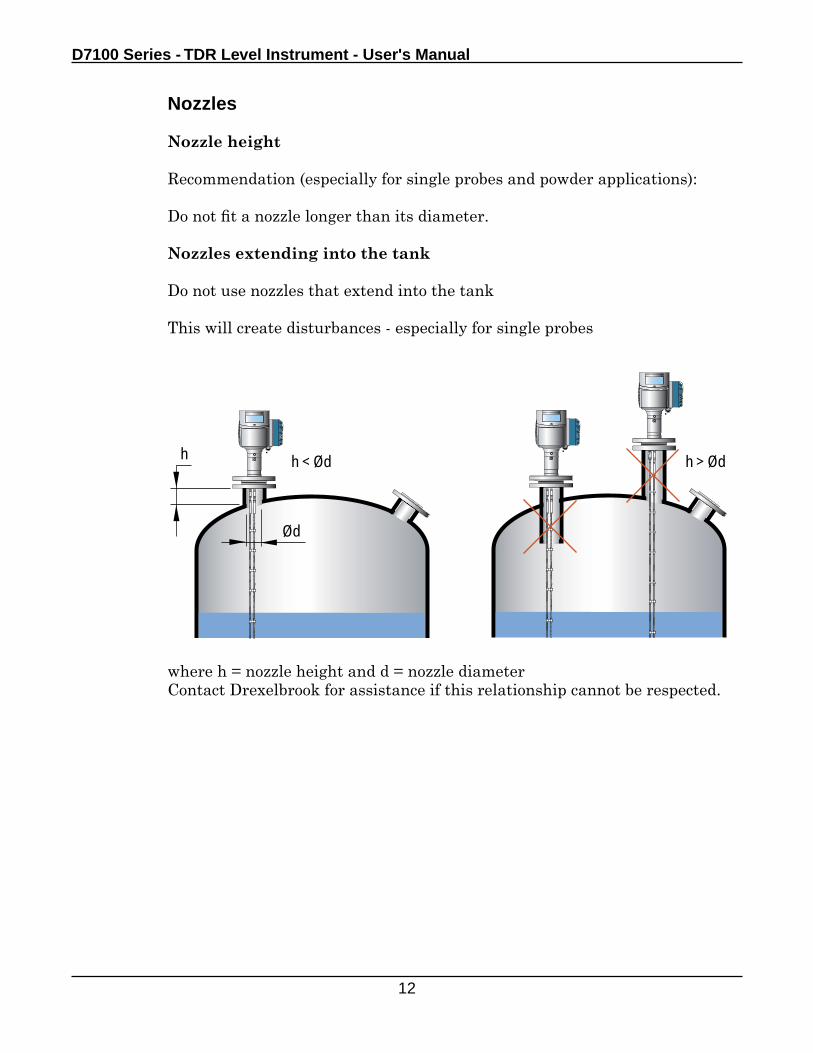
Nozzles
Nozzle height
Recommendation (especially for single probes and powder applications):
Do not fit a nozzle longer than its diameter.
Nozzles extending into the tank
Do not use nozzles that extend into the tank
This will create disturbances - especially for single probes
where h = nozzle height and d = nozzle diameterContact Drexelbrook for assistance if this relationship cannot be respected.
Location
13
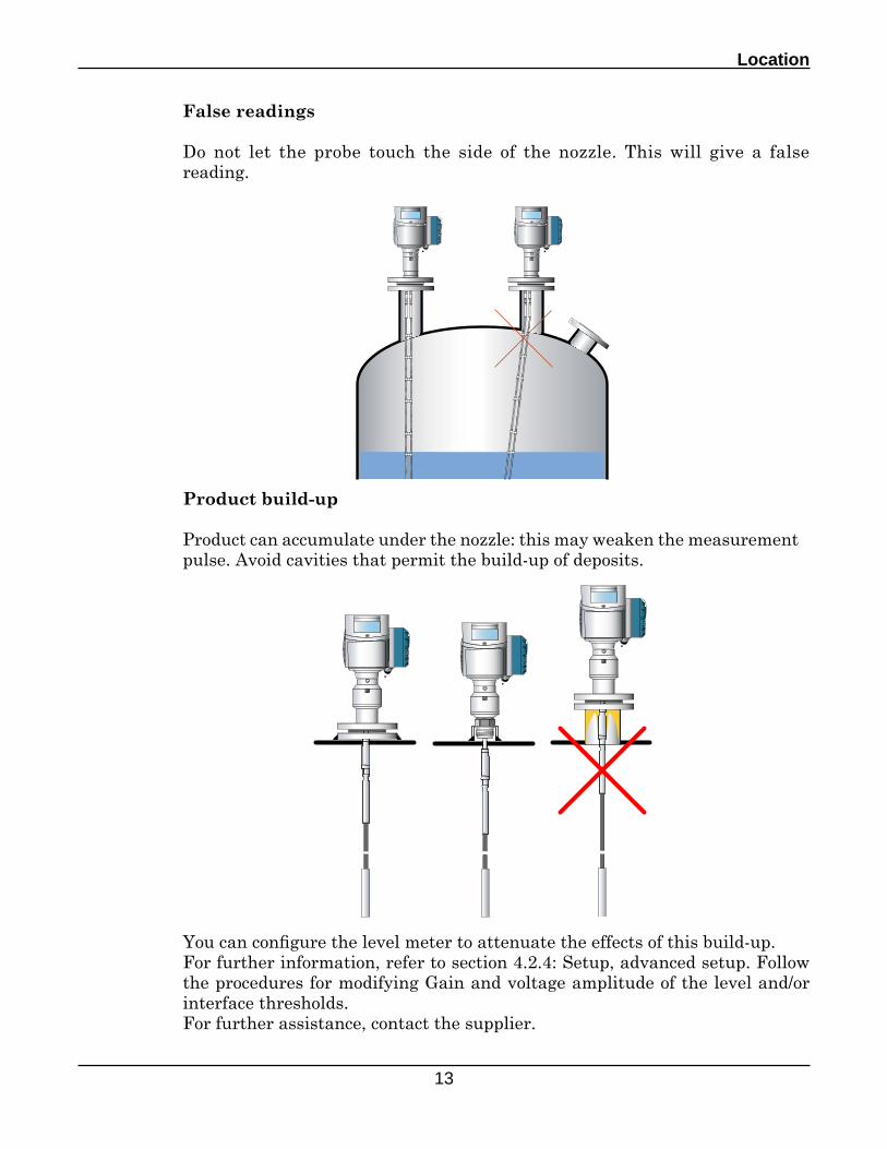
False readings
Do not let the probe touch the side of the nozzle. This will give a false reading.
Product build-up
Product can accumulate under the nozzle: this may weaken the measurement pulse. Avoid cavities that permit the build-up of deposits.
You can configure the level meter to attenuate the effects of this build-up.For further information, refer to section 4.2.4: Setup, advanced setup. Follow the procedures for modifying Gain and voltage amplitude of the level and/or interface thresholds.For further assistance, contact the supplier.
D7100 Series - TDR Level Instrument - User's Manual
14
>1m
/ 3.
3ft
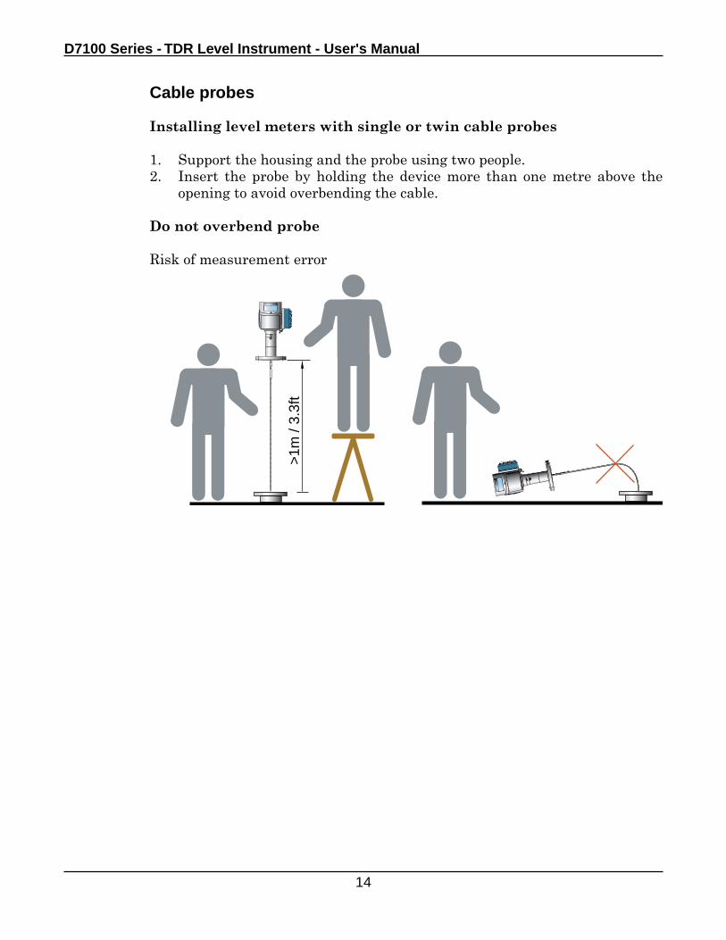
Cable probes
Installing level meters with single or twin cable probes
1. Support the housing and the probe using two people.2. Insert the probe by holding the device more than one metre above the
opening to avoid overbending the cable.
Do not overbend probe
Risk of measurement error
Location
15
Lr
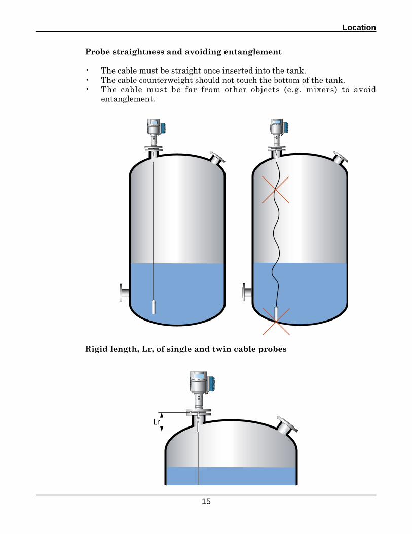
Probe straightness and avoiding entanglement
• The cable must be straight once inserted into the tank.• The cable counterweight should not touch the bottom of the tank.• The cable must be far from other objects (e.g. mixers) to avoid
entanglement.
Rigid length, Lr, of single and twin cable probes
D7100 Series - TDR Level Instrument - User's Manual
16
1.2 Installation relative to other tank components
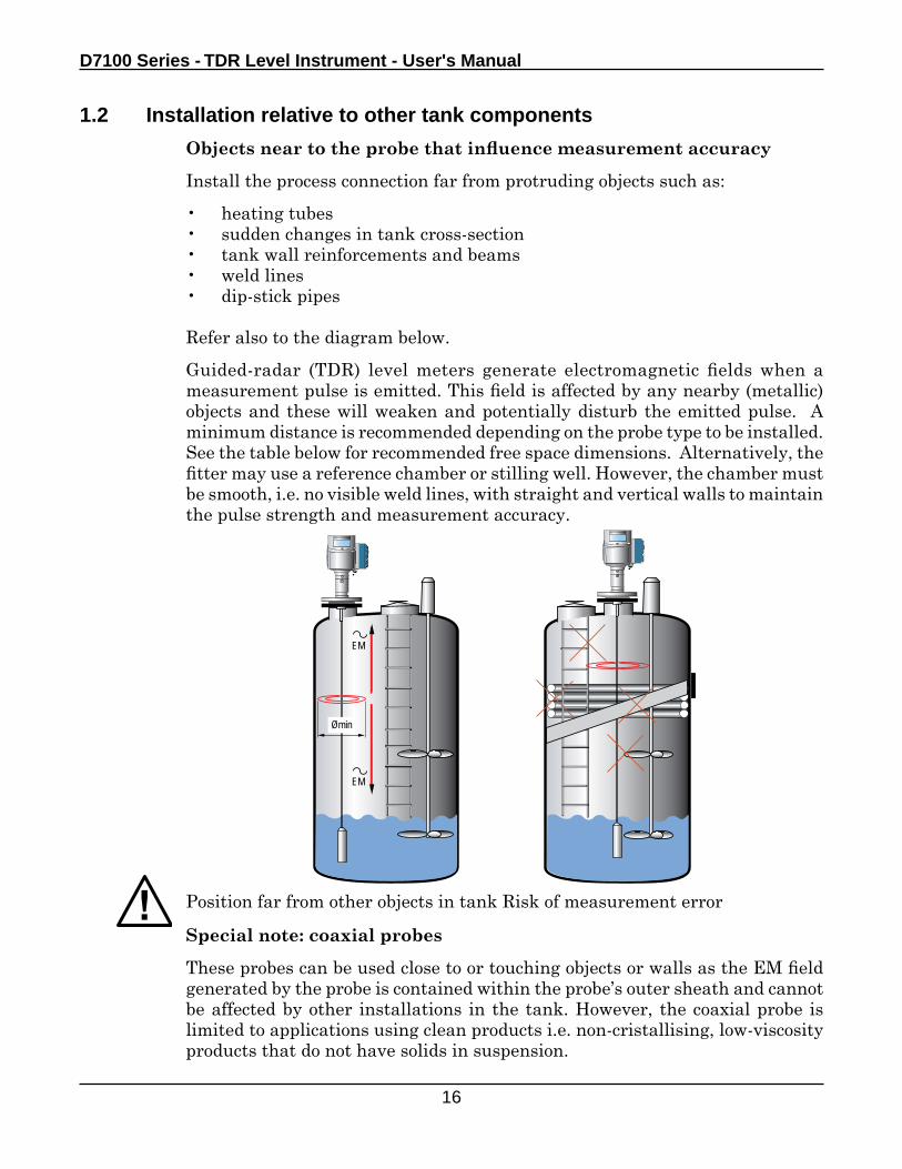
Objects near to the probe that influence measurement accuracy
Install the process connection far from protruding objects such as:
• heating tubes• sudden changes in tank cross-section• tank wall reinforcements and beams• weld lines• dip-stick pipes
Refer also to the diagram below.
Guided-radar (TDR) level meters generate electromagnetic fields when a measurement pulse is emitted. This field is affected by any nearby (metallic) objects and these will weaken and potentially disturb the emitted pulse. A minimum distance is recommended depending on the probe type to be installed. See the table below for recommended free space dimensions. Alternatively, the fitter may use a reference chamber or stilling well. However, the chamber must be smooth, i.e. no visible weld lines, with straight and vertical walls to maintain the pulse strength and measurement accuracy.
EM
EM
Ømin
Position far from other objects in tank Risk of measurement error
Special note: coaxial probes
These probes can be used close to or touching objects or walls as the EM field generated by the probe is contained within the probe’s outer sheath and cannot be affected by other installations in the tank. However, the coaxial probe is limited to applications using clean products i.e. non-cristallising, low-viscosity products that do not have solids in suspension.
Location
17
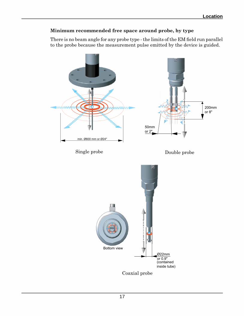
Minimum recommended free space around probe, by type
There is no beam angle for any probe type - the limits of the EM field run parallel to the probe because the measurement pulse emitted by the device is guided.
Single probe Double probe
Coaxial probe
D7100 Series - TDR Level Instrument - User's Manual
18
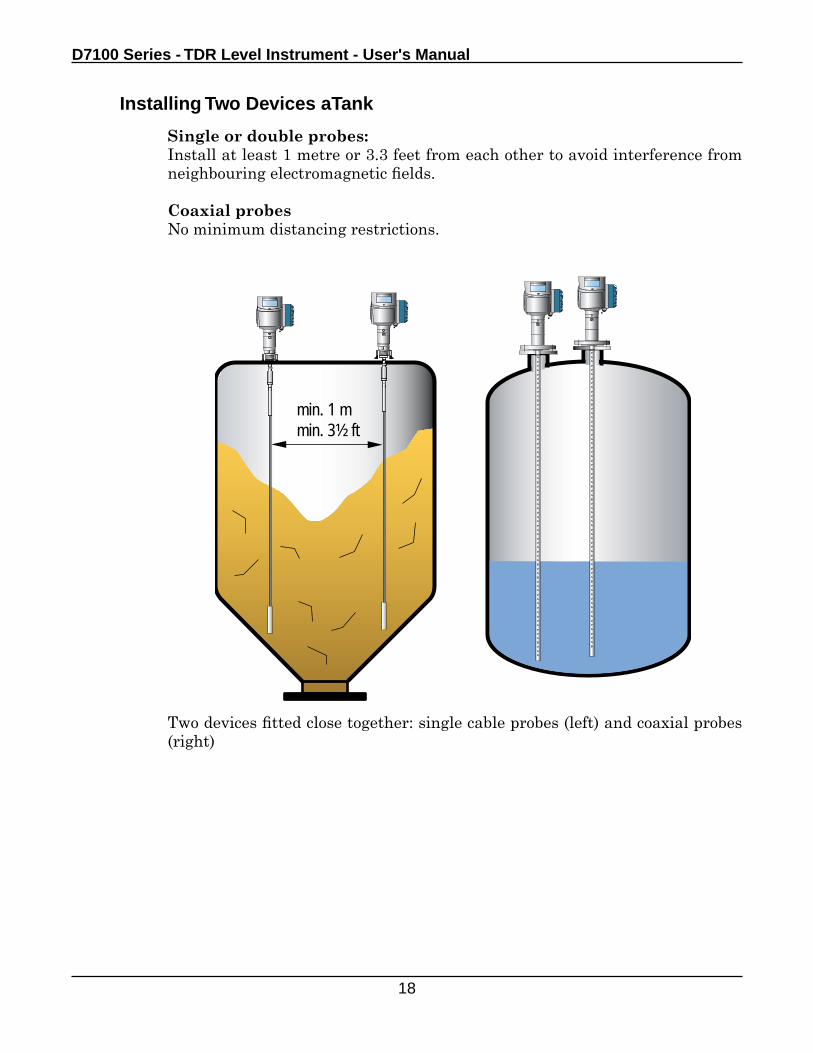
Single or double probes:Install at least 1 metre or 3.3 feet from each other to avoid interference from neighbouring electromagnetic fields.
Coaxial probesNo minimum distancing restrictions.
Installing Two Devices aTank
min. 1 mmin. 3½ ft
Two devices fitted close together: single cable probes (left) and coaxial probes (right)
Location
19
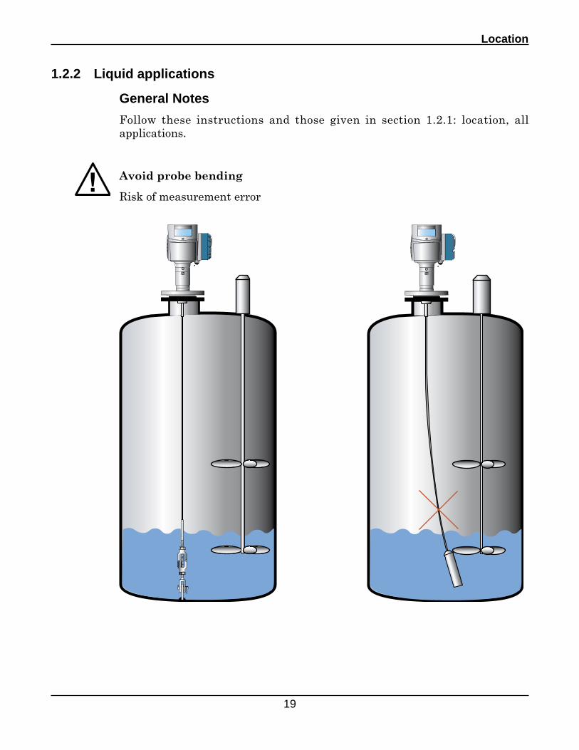
1.2.2 Liquid applications
General Notes
Follow these instructions and those given in section 1.2.1: location, all applications.
Avoid probe bending
Risk of measurement error
D7100 Series - TDR Level Instrument - User's Manual
20
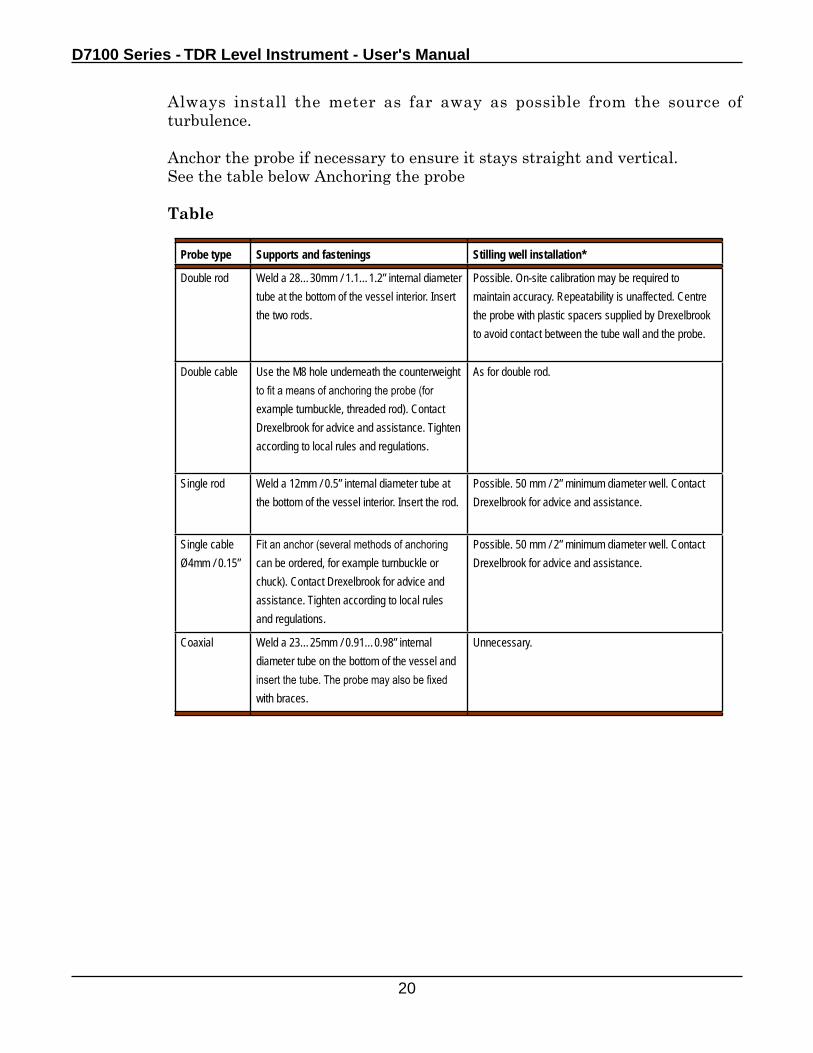
Always install the meter as far away as possible from the source of turbulence.
Anchor the probe if necessary to ensure it stays straight and vertical. See the table below Anchoring the probe
Table
Probe type Supports and fastenings Stilling well installation*
Double rod Weld a 28…30mm / 1.1…1.2” internal diameter tube at the bottom of the vessel interior. Insert the two rods.
Possible. On-site calibration may be required to maintain accuracy. Repeatability is unaffected. Centre the probe with plastic spacers supplied by Drexelbrook to avoid contact between the tube wall and the probe.
Double cable Use the M8 hole underneath the counterweight to fit a means of anchoring the probe (for example turnbuckle, threaded rod). Contact Drexelbrook for advice and assistance. Tighten according to local rules and regulations.
As for double rod.
Single rod Weld a 12mm / 0.5” internal diameter tube at the bottom of the vessel interior. Insert the rod.
Possible. 50 mm / 2” minimum diameter well. Contact Drexelbrook for advice and assistance.
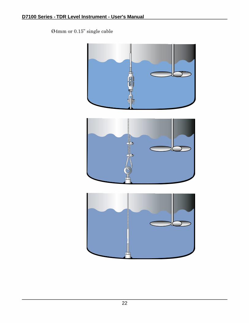
Single cable Ø4mm / 0.15”
Fit an anchor (several methods of anchoring can be ordered, for example turnbuckle or chuck). Contact Drexelbrook for advice and assistance. Tighten according to local rules and regulations.
Possible. 50 mm / 2” minimum diameter well. Contact Drexelbrook for advice and assistance.
Coaxial Weld a 23…25mm / 0.91…0.98” internal diameter tube on the bottom of the vessel and insert the tube. The probe may also be fixed with braces.
Unnecessary.
Location
21
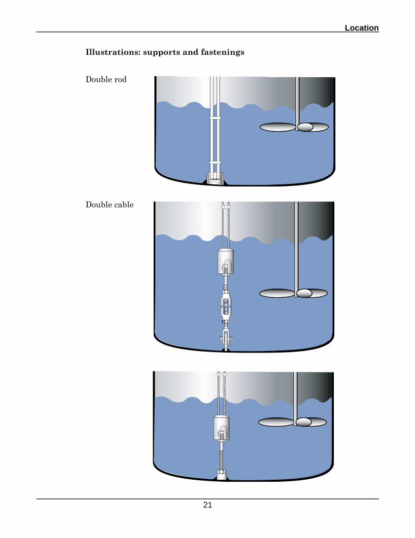
Illustrations: supports and fastenings
Double rod
Double cable
D7100 Series - TDR Level Instrument - User's Manual
22
Ø4mm or 0.15” single cable
Location
23
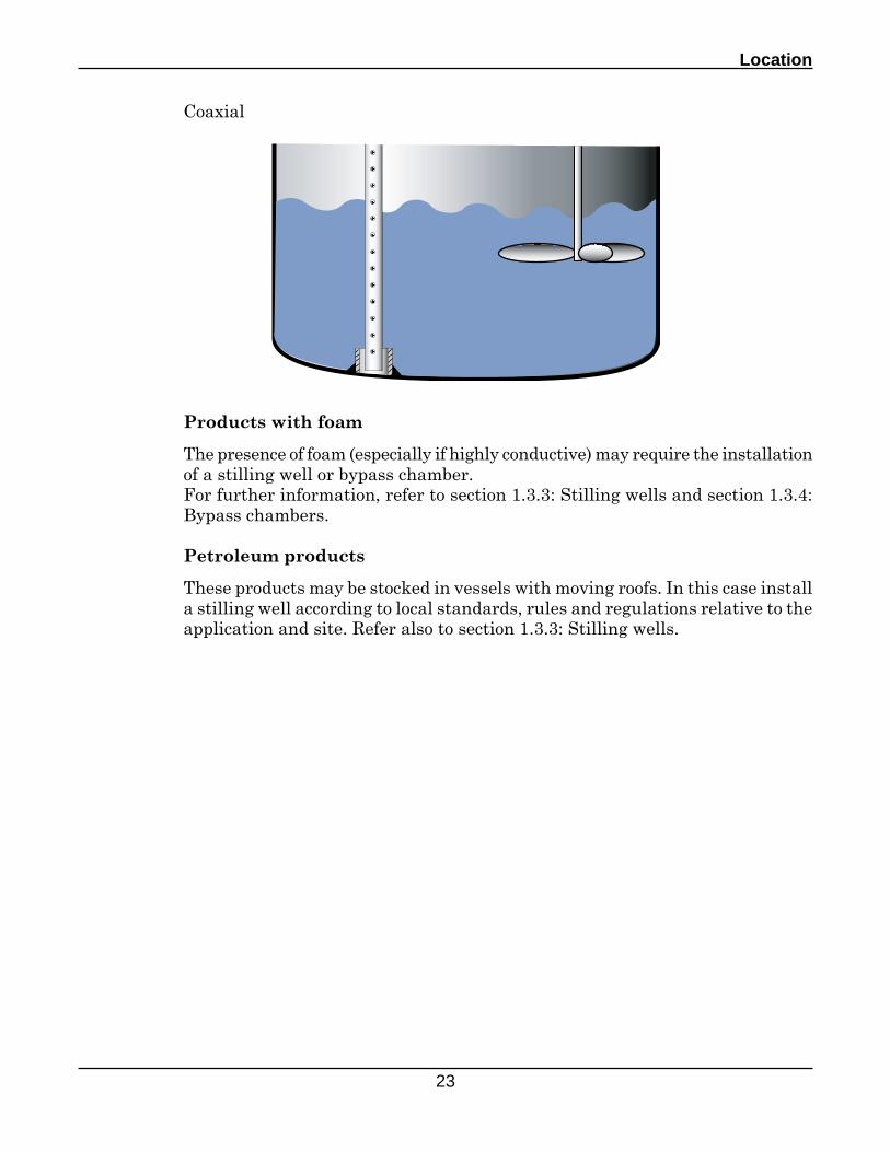
Products with foam
The presence of foam (especially if highly conductive) may require the installation of a stilling well or bypass chamber.For further information, refer to section 1.3.3: Stilling wells and section 1.3.4: Bypass chambers.
Petroleum products
These products may be stocked in vessels with moving roofs. In this case install a stilling well according to local standards, rules and regulations relative to the application and site. Refer also to section 1.3.3: Stilling wells.
Coaxial
D7100 Series - TDR Level Instrument - User's Manual
24
> 10 m or 33 ft
1/2 R R
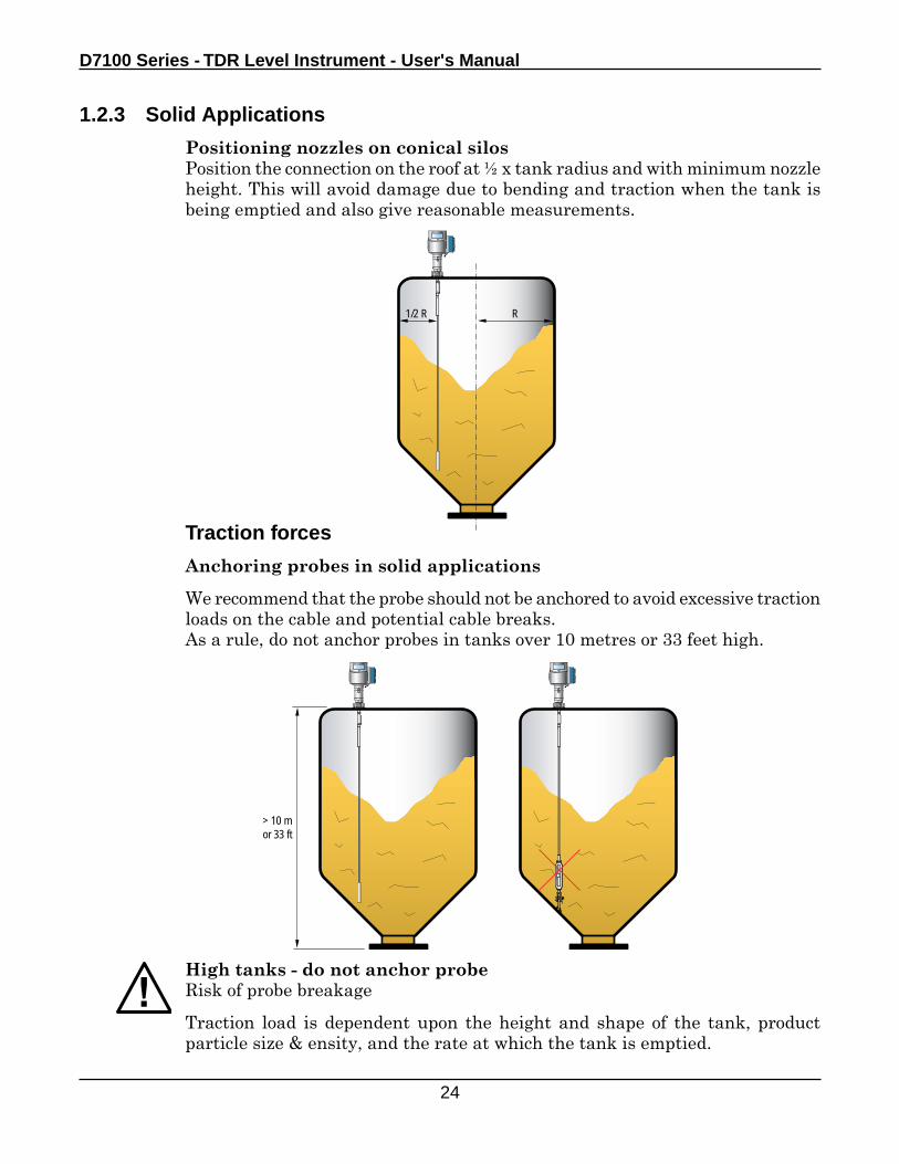
1.2.3 Solid Applications
Positioning nozzles on conical silosPosition the connection on the roof at ½ x tank radius and with minimum nozzle height. This will avoid damage due to bending and traction when the tank is being emptied and also give reasonable measurements.
Traction forces
Anchoring probes in solid applications
We recommend that the probe should not be anchored to avoid excessive traction loads on the cable and potential cable breaks.As a rule, do not anchor probes in tanks over 10 metres or 33 feet high.
High tanks - do not anchor probeRisk of probe breakage
Traction load is dependent upon the height and shape of the tank, product particle size & ensity, and the rate at which the tank is emptied.
Location
25
> 3.5T or 7700lbs
3.5T or 7700lbs3.5T or 7700lbs
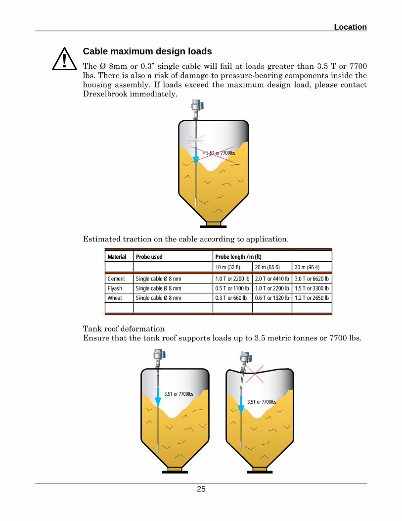
Cable maximum design loads
The Ø 8mm or 0.3” single cable will fail at loads greater than 3.5 T or 7700 lbs. There is also a risk of damage to pressure-bearing components inside the housing assembly. If loads exceed the maximum design load, please contact Drexelbrook immediately.
Tank roof deformationEnsure that the tank roof supports loads up to 3.5 metric tonnes or 7700 lbs.
Estimated traction on the cable according to application.
Material Probe used Probe length / m (ft)10 m (32.8) 20 m (65.6) 30 m (96.4)
Cement Single cable Ø 8 mm 1.0 T or 2200 lb 2.0 T or 4410 lb 3.0 T or 6620 lbFlyash Single cable Ø 8 mm 0.5 T or 1100 lb 1.0 T or 2200 lb 1.5 T or 3300 lbWheat Single cable Ø 8 mm 0.3 T or 660 lb 0.6 T or 1320 lb 1.2 T or 2650 lb
D7100 Series - TDR Level Instrument - User's Manual
26
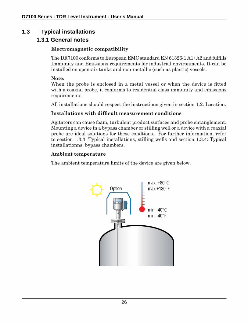
max. +80°Cmax.+180°F
min. -40°Cmin. -40°F
Option
1.3 Typical installations1.3.1 General notes
Electromagnetic compatibility
The DR7100 conforms to European EMC standard EN 61326-1 A1+A2 and fulfills Immunity and Emissions requirements for industrial environments. It can be installed on open-air tanks and non-metallic (such as plastic) vessels.
Note:When the probe is enclosed in a metal vessel or when the device is fitted with a coaxial probe, it conforms to residential class immunity and emissions requirements.
All installations should respect the instructions given in section 1.2: Location.
Installations with difficult measurement conditions
Agitators can cause foam, turbulent product surfaces and probe entanglement. Mounting a device in a bypass chamber or stilling well or a device with a coaxial probe are ideal solutions for these condtions. For further information, refer to section 1.3.3: Typical installations, stilling wells and section 1.3.4: Typical installationns, bypass chambers.
Ambient temperature
The ambient temperature limits of the device are given below.
Location
27
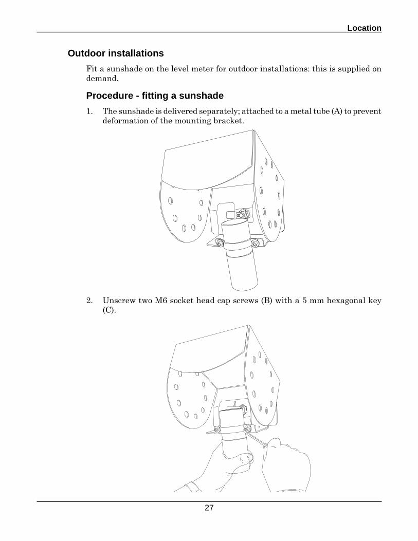
Outdoor installations
Fit a sunshade on the level meter for outdoor installations: this is supplied on demand.
Procedure - fitting a sunshade
1. The sunshade is delivered separately; attached to a metal tube (A) to prevent deformation of the mounting bracket.
2. Unscrew two M6 socket head cap screws (B) with a 5 mm hexagonal key (C).
D7100 Series - TDR Level Instrument - User's Manual
28
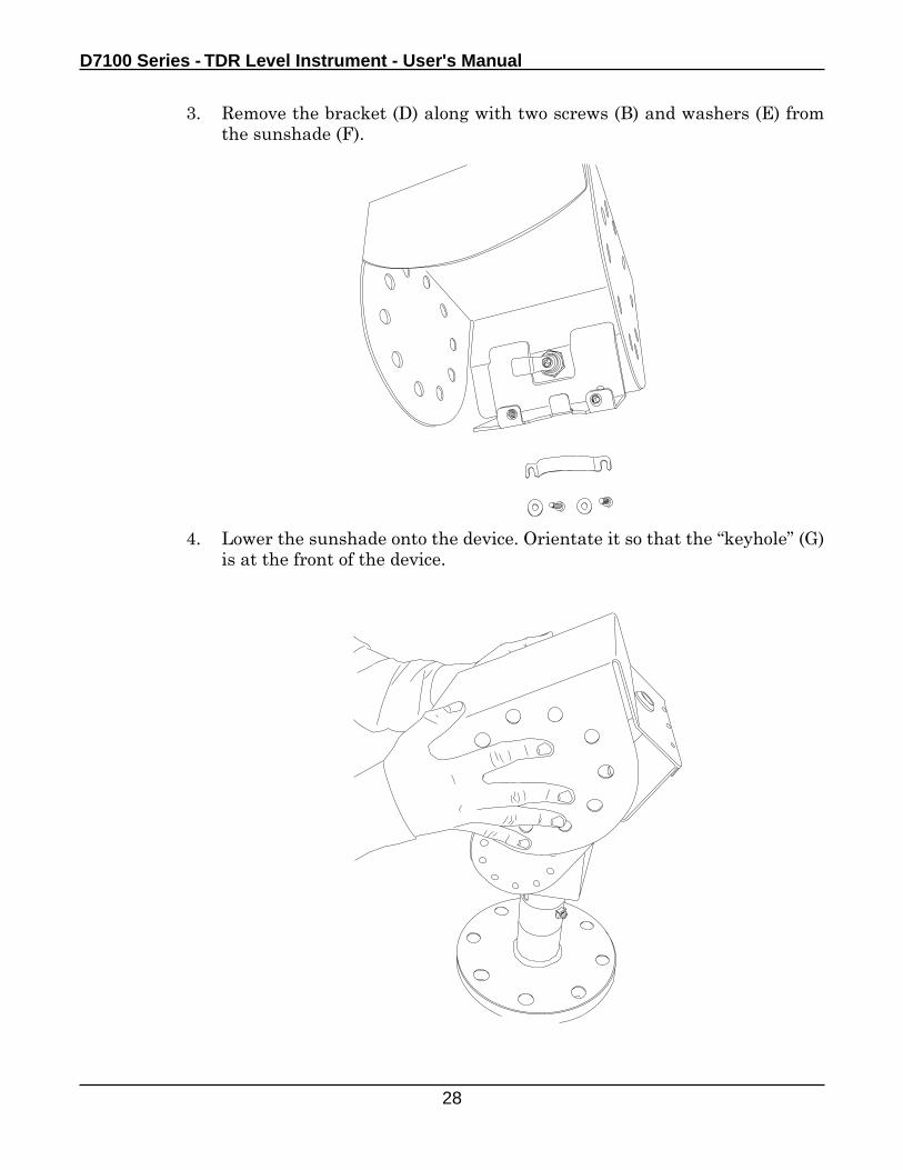
3. Remove the bracket (D) along with two screws (B) and washers (E) from the sunshade (F).
4. Lower the sunshade onto the device. Orientate it so that the “keyhole” (G) is at the front of the device.
Location
29
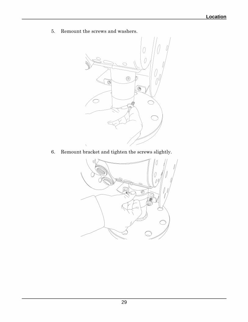
5. Remount the screws and washers.
6. Remount bracket and tighten the screws slightly.
D7100 Series - TDR Level Instrument - User's Manual
30
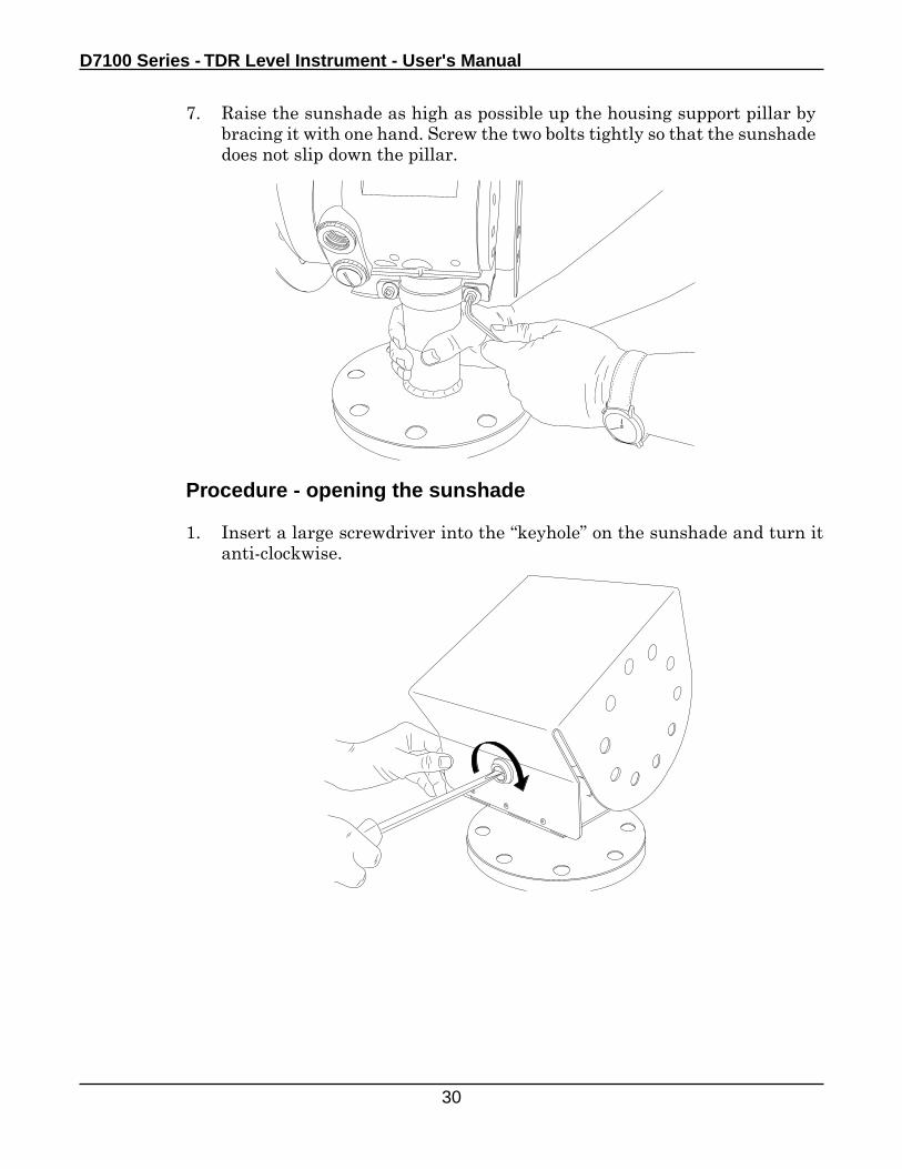
Procedure - opening the sunshade
1. Insert a large screwdriver into the “keyhole” on the sunshade and turn it anti-clockwise.
7. Raise the sunshade as high as possible up the housing support pillar by bracing it with one hand. Screw the two bolts tightly so that the sunshade does not slip down the pillar.
Location
31
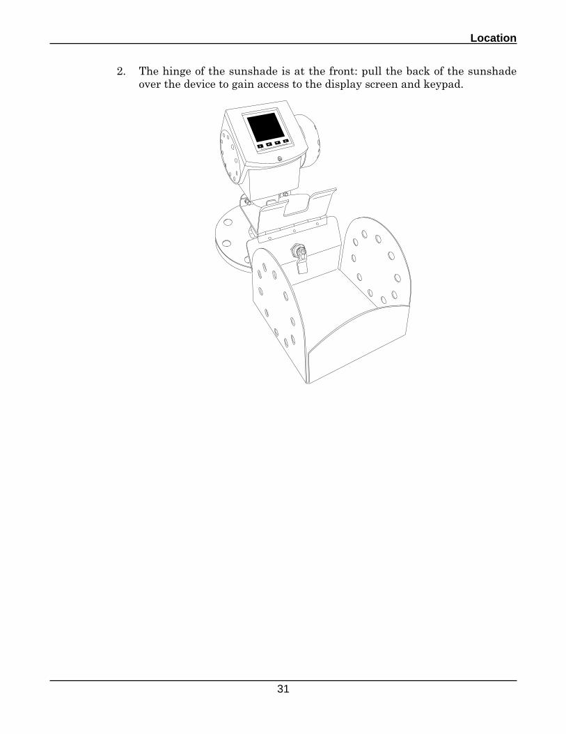
2. The hinge of the sunshade is at the front: pull the back of the sunshade over the device to gain access to the display screen and keypad.
Esc
D7100 Series - TDR Level Instrument - User's Manual
32
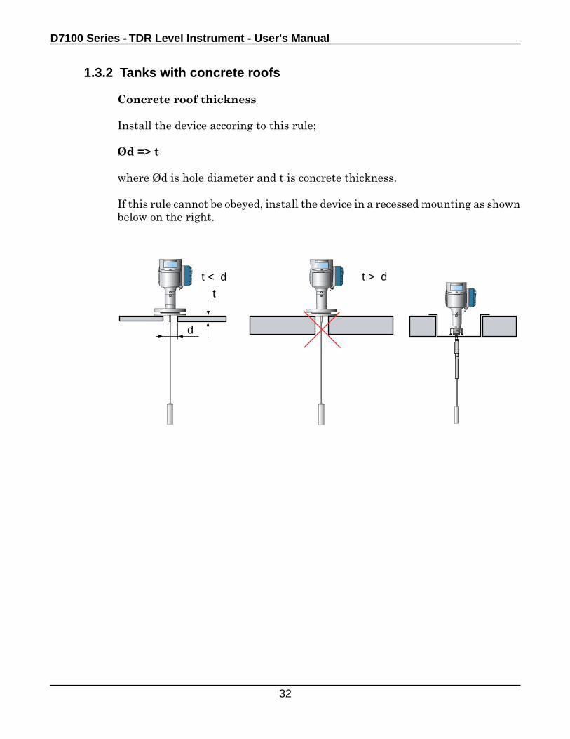
1.3.2 Tanks with concrete roofs
Concrete roof thickness
Install the device accoring to this rule;
Ød => t
where Ød is hole diameter and t is concrete thickness.
If this rule cannot be obeyed, install the device in a recessed mounting as shown below on the right.
d
t
t > dt < d
Location
33
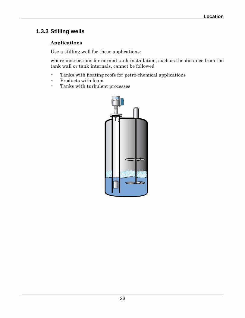
1.3.3 Stilling wells
Applications
Use a stilling well for these applications:
where instructions for normal tank installation, such as the distance from the tank wall or tank internals, cannot be followed
• Tanks with floating roofs for petro-chemical applications• Products with foam• Tanks with turbulent processes
D7100 Series - TDR Level Instrument - User's Manual
34
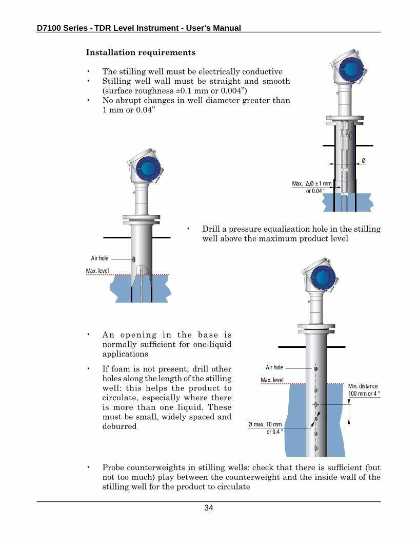
Installation requirements
• The stilling well must be electrically conductive• Stilling well wall must be straight and smooth
(surface roughness ±0.1 mm or 0.004”)• No abrupt changes in well diameter greater than
1 mm or 0.04”
Max. Ø ±1 mm or 0.04 "
Ø
• Drill a pressure equalisation hole in the stilling well above the maximum product level
• An opening in the base is normally sufficient for one-liquid applications
• If foam is not present, drill other holes along the length of the stilling well: this helps the product to circulate, especially where there is more than one liquid. These must be small, widely spaced and deburred
Max. level
Air hole
Max. level
Air hole
Min. distance 100 mm or 4 "
Ø max. 10 mm or 0.4 "
• Probe counterweights in stilling wells: check that there is sufficient (but not too much) play between the counterweight and the inside wall of the stilling well for the product to circulate
Location
35
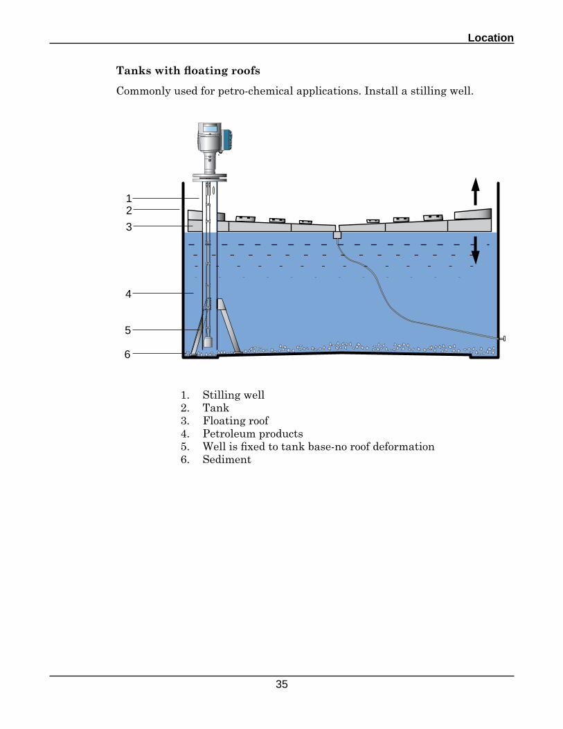
Tanks with floating roofs
Commonly used for petro-chemical applications. Install a stilling well.
1. Stilling well2. Tank3. Floating roof4. Petroleum products5. Well is fixed to tank base-no roof deformation6. Sediment
12
3
4
5
6
D7100 Series - TDR Level Instrument - User's Manual
36
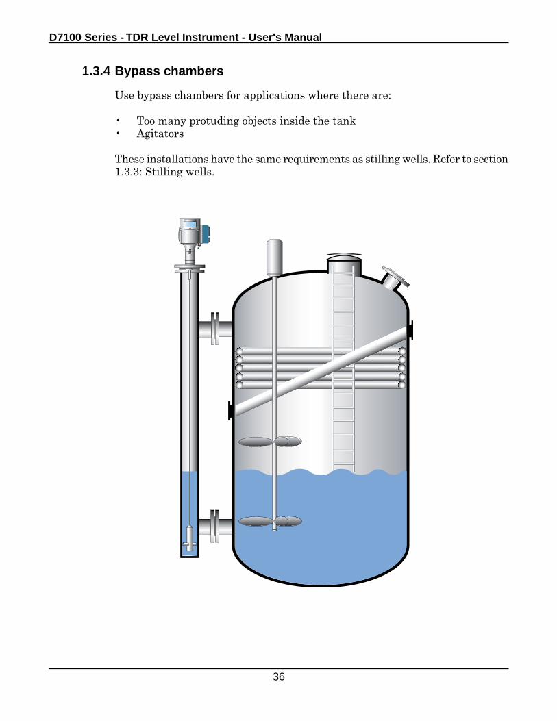
1.3.4 Bypass chambers
Use bypass chambers for applications where there are:
• Too many protuding objects inside the tank • Agitators
These installations have the same requirements as stilling wells. Refer to section 1.3.3: Stilling wells.
Location
37
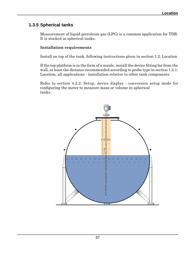
1.3.5 Spherical tanks
Measurement of liquid petroleum gas (LPG) is a common application for TDR. It is stocked in spherical tanks.
Installation requirements
Install on top of the tank, following instructions given in section 1.2: Location
If the top platform is in the form of a nozzle, install the device fitting far from the wall, at least the distance recommended according to probe type in section 1.2.1: Location, all applications - installation relative to other tank components
Refer to section 4.2.2: Setup, device display - conversion setup mode for configuring the meter to measure mass or volume in sphericaltanks.
D7100 Series - TDR Level Instrument - User's Manual
38
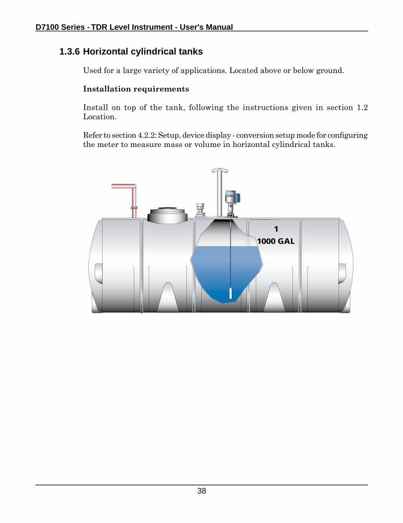
1.3.6 Horizontal cylindrical tanks
Used for a large variety of applications. Located above or below ground.
Installation requirements
Install on top of the tank, following the instructions given in section 1.2 Location.
Refer to section 4.2.2: Setup, device display - conversion setup mode for configuring the meter to measure mass or volume in horizontal cylindrical tanks.
11000 GAL
Location
39
1.4 Other important information
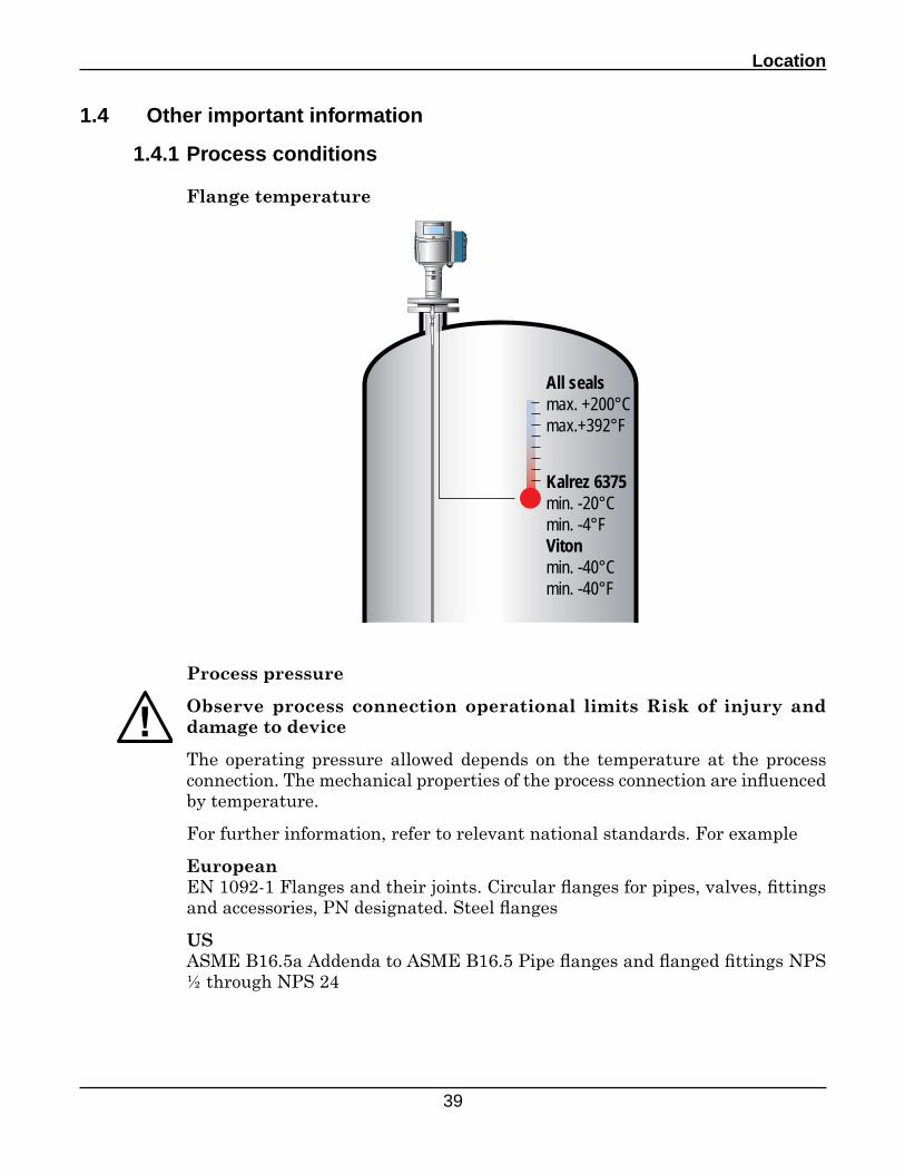
1.4.1 Process conditions
Flange temperature
Process pressure
Observe process connection operational limits Risk of injury and damage to device
The operating pressure allowed depends on the temperature at the process connection. The mechanical properties of the process connection are influenced by temperature.
For further information, refer to relevant national standards. For example
EuropeanEN 1092-1 Flanges and their joints. Circular flanges for pipes, valves, fittings and accessories, PN designated. Steel flanges
USASME B16.5a Addenda to ASME B16.5 Pipe flanges and flanged fittings NPS ½ through NPS 24
All sealsmax. +200°Cmax.+392°F
Kalrez 6375 min. -20°Cmin. -4°FVitonmin. -40°Cmin. -40°F
D7100 Series - TDR Level Instrument - User's Manual
40
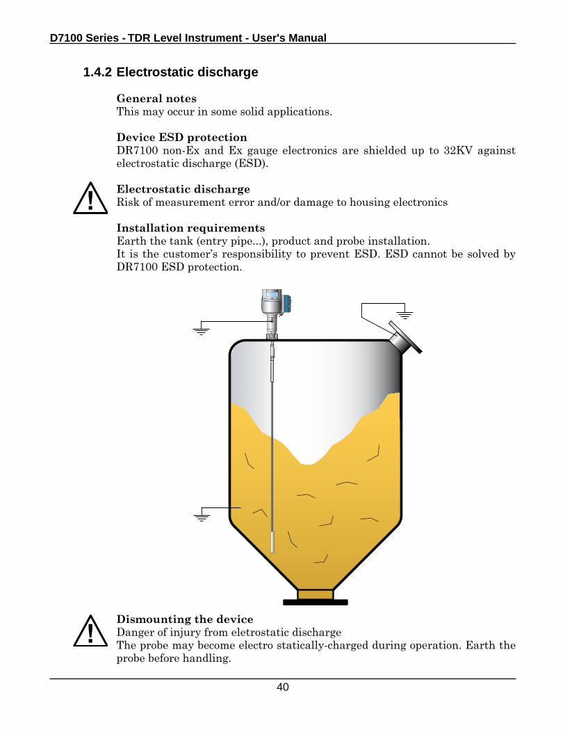
Dismounting the deviceDanger of injury from eletrostatic dischargeThe probe may become electro statically-charged during operation. Earth the probe before handling.
1.4.2 Electrostatic discharge
General notesThis may occur in some solid applications.
Device ESD protectionDR7100 non-Ex and Ex gauge electronics are shielded up to 32KV against electrostatic discharge (ESD).
Electrostatic dischargeRisk of measurement error and/or damage to housing electronics
Installation requirementsEarth the tank (entry pipe...), product and probe installation.It is the customer’s responsibility to prevent ESD. ESD cannot be solved by DR7100 ESD protection.
Electrical Connection
41
2.0 Electrical connection
2.1 Wiring
Cable entryElectrical connection is made through two cable entries located at the back of the housing. The cable entries can be ordered with adaptors• M20 x• 1.5• ½NPT• G½
Cable glands are only supplied with non-Ex and EEx ia-approved devices. You must supply the cable glands for EEx d and FM-approved devices.
Access to terminals is via a blue threaded cover on the side of the housing. As the device is a 2-wire instrument, the power supply and the output signal transmitted by the device use the same cable.
Reminder of wiring fundamentals
Power supplyDisconnect the power supply before wiring the device
Cables• Use metal cable glands and reinforced, shielded cable to minimise RFI
(radio frequency interference) and/or EMI (electromagnetic interference)• Observe applicable local rules and regulations for wiring• Always use the cable entry facing the terminal• Avoid crossing or looping wires• Add sufficient length to make U-bends in the cable to provide water with
run-off points• Do not let the cable come into contact with hot or potentially hot surfaces
such as the flange• Avoid kinks in the cable close to the cable entry glands by adding sufficient
cable length. Reinforce with a metal sheath at this point, if necessary
Device protection• If overcurrent is expected, install an overcurrent protection device• Earth the device according to applicable local installation standards
American and Canadian installations• The device must be wired by a qualified electrician in accordance with the
latest version of National Electric Code for installations in the USA or Canadian Electric Code for installations in Canada and local regulations
• Check that all wiring is rated 20°C or 68°F above ambient temperature, especially where the cable exits a conduit near to the device.
D7100 Series - TDR Level Instrument - User's Manual
42
Supply voltage
The device requires a supply voltage that depends on which output terminal is used and the approval option ordered.Refer to section 2.2: Power supply for this information.
Hazardous areasFor information on wiring devices approved for use in hazardous areas, refer to the approval certificate and special manuals supplied with the device. See also Standards and Approvals.
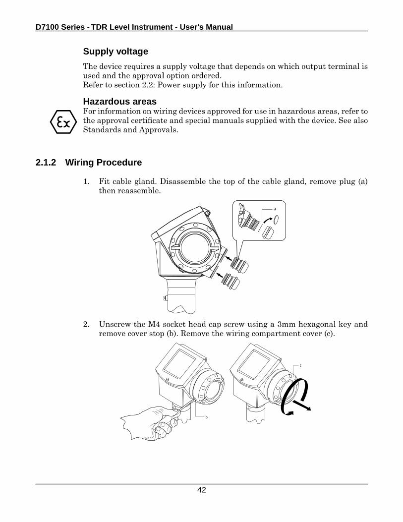
2.1.2 Wiring Procedure
1. Fit cable gland. Disassemble the top of the cable gland, remove plug (a) then reassemble.
2. Unscrew the M4 socket head cap screw using a 3mm hexagonal key and remove cover stop (b). Remove the wiring compartment cover (c).
a
b
c
Electrical Connection
43
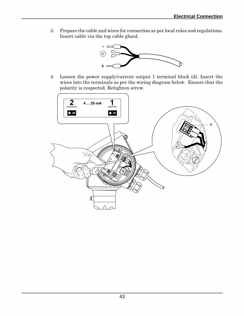
3. Prepare the cable and wires for connection as per local rules and regulations. Insert cable via the top cable gland.
4. Loosen the power supply/current output 1 terminal block (d). Insert the wires into the terminals as per the wiring diagram below. Ensure that the polarity is respected. Retighten screw.
+
-
d
D7100 Series - TDR Level Instrument - User's Manual
44
e
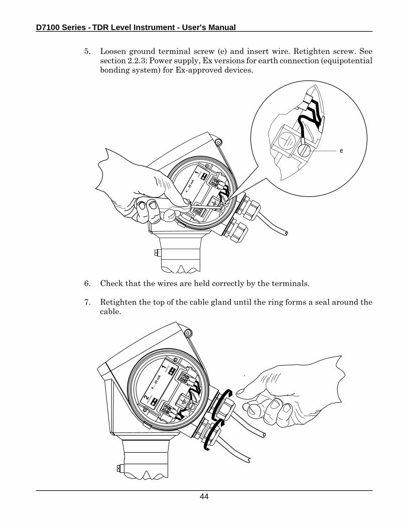
6. Check that the wires are held correctly by the terminals.
7. Retighten the top of the cable gland until the ring forms a seal around the cable.
5. Loosen ground terminal screw (e) and insert wire. Retighten screw. See section 2.2.3: Power supply, Ex versions for earth connection (equipotential bonding system) for Ex-approved devices.
Electrical Connection
45
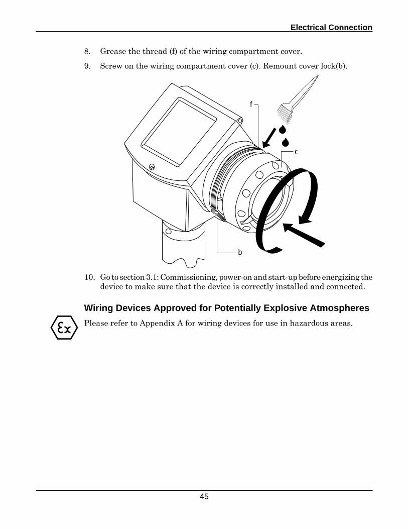
8. Grease the thread (f) of the wiring compartment cover.
9. Screw on the wiring compartment cover (c). Remount cover lock(b).
10. Go to section 3.1: Commissioning, power-on and start-up before energizing the device to make sure that the device is correctly installed and connected.
c
b
f
Wiring Devices Approved for Potentially Explosive Atmospheres
Please refer to Appendix A for wiring devices for use in hazardous areas.
D7100 Series - TDR Level Instrument - User's Manual
46
2.2 Power supply
2.2.1 General notes
Each output requires its own power supply.
Supply voltage outside of given limits
Check that the device uses the correct power supply
• A supply voltage above the maximum value can cause irreparable damage to the signal converter.
• Voltages above and below the specified limits can also lead to faulty measurements or to a device reset.
Refer to technical data in section 2.2.2: Power supply, non-Ex version. If the device is approved for use in potentially explosive atmospheres, refer also special manuals included with the device.
Power supply polarity
Observe the correct polarity for the devic’s electrical system. • The device will not function if the polarity is reversed
Factors influencing supply voltage
Allow for voltage drop caused by the circuit load impedance (loop resistance). This includes the resistance of:
• The cable
• Other devices in the circuit
• Resistors for connection of device tool managers and HART® controllers
Electrical Connection
47
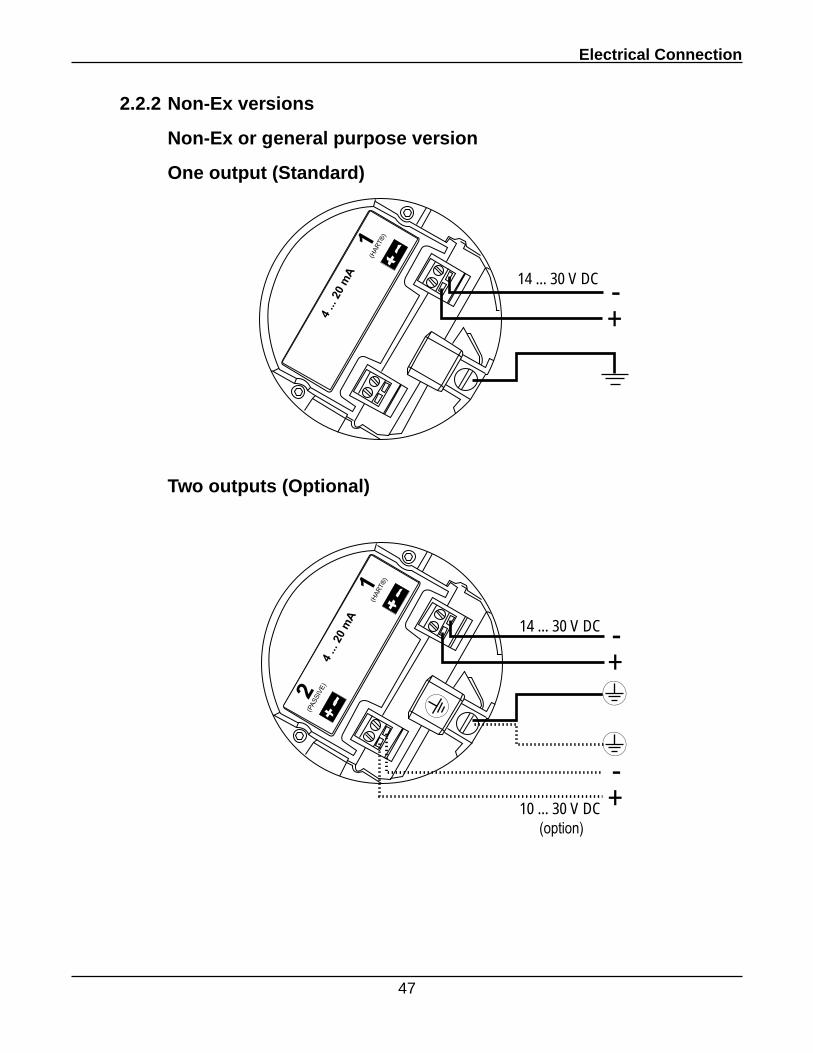
2.2.2 Non-Ex versions
Non-Ex or general purpose version
One output (Standard)
14 ... 30 V DC
+-
Two outputs (Optional)
14 ... 30 V DC
10 ... 30 V DC(option)
+-
+-
D7100 Series - TDR Level Instrument - User's Manual
48
2.2.3 Ex versions
Please refer to Appendix A if approved for use in potentially explosive atmospheres.
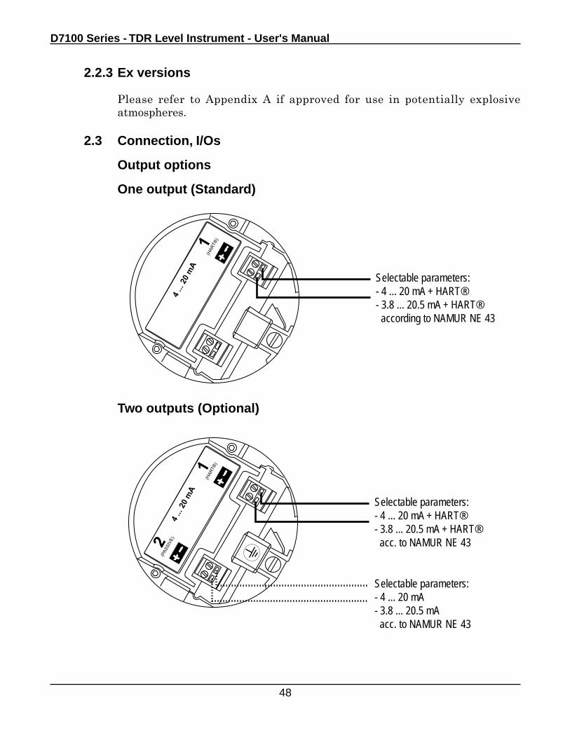
2.3 Connection, I/Os
Output options
One output (Standard)
Two outputs (Optional)
Selectable parameters:- 4 ... 20 mA + HART®- 3.8 ... 20.5 mA + HART® according to NAMUR NE 43
Selectable parameters:- 4 ... 20 mA + HART®- 3.8 ... 20.5 mA + HART® acc. to NAMUR NE 43
Selectable parameters:- 4 ... 20 mA- 3.8 ... 20.5 mA acc. to NAMUR NE 43
Electrical Connection
49
Network options
There are 3 output versions
• Current output HART®, passive, HART® protocol
• Current output Ex-ia HART® intrinsically safe; passive, HART® protocol
• Current output Ex-d ia HART® explosion-proof; passive, HART® protocol
The last two versions are discussed in special manuals for devices approved for use in explosive atmospheres.
Two network modes are available
• Point-to-point
• Multi-drop
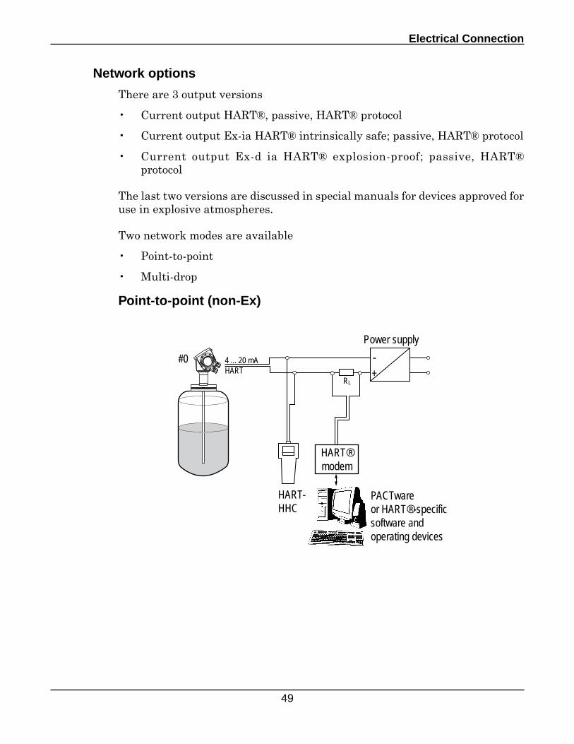
Point-to-point (non-Ex)
HART-HHC
PACTwareor HART®-specific software and operating devices
4 ... 20 mAHART
-+
Power supply
HART®modem
RL
#0
D7100 Series - TDR Level Instrument - User's Manual
50
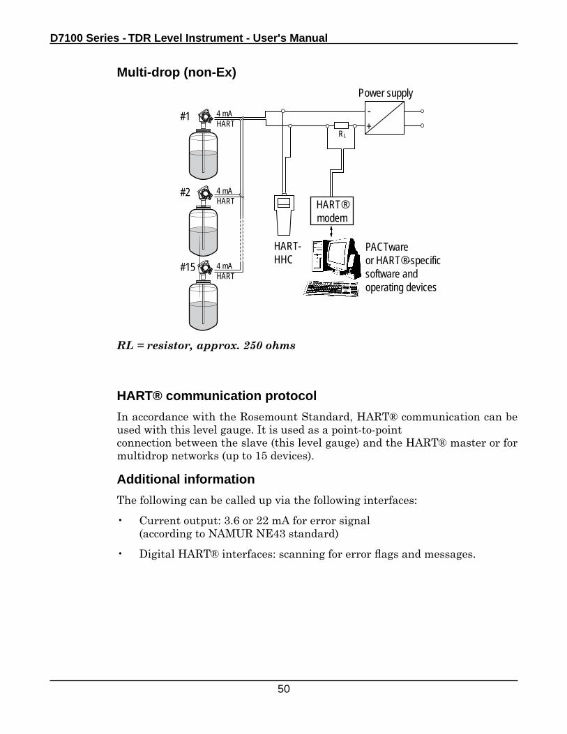
Multi-drop (non-Ex)
RL = resistor, approx. 250 ohms
HART-HHC
PACTwareor HART®-specific software and operating devices
4 mAHART
-+
Power supply
HART®modem
4 mAHART
4 mAHART
#1
#2
#15
RL
HART® communication protocol
In accordance with the Rosemount Standard, HART® communication can be used with this level gauge. It is used as a point-to-pointconnection between the slave (this level gauge) and the HART® master or for multidrop networks (up to 15 devices).
Additional information
The following can be called up via the following interfaces:
• Current output: 3.6 or 22 mA for error signal (according to NAMUR NE43 standard)
• Digital HART® interfaces: scanning for error flags and messages.
Electrical Connection
51
Changing from point-to-point to multi-drop network mode
The device’s output 1 communicates by default in point-to-point mode (HART address 0). If you wish for the device to communicate in multi-drop mode then you have to modify the output’s HART address. Use the following procedure
Procedure (using the display screen configuration wizard)
1. Enter Program Mode (Press right key for three seconds)
2. Either go to Quick Setup > Setup mode > Outputs and go through the setup procedure until you get to OP1 (output 1) HART Address
...or... go to Advanced Setup > Output 1 (HART) and find the menu item HART
Address
3. Type in a value between 1 and 15 (default is 0 - point-to-point mode). This will switch output 1 over to multi-drop mode.
4. Check that outputs of other devices in the network do not have the same HART address
5. Exit to Normal Mode
For further information on device operation and configuration, please refer to section 4.1: Operating concept and section 4.2: Setup.
A definition of the menu item HART address is given in section 4.2.3 Setup, summary of user functions under C.4.5.0 HART address.
Networks using Ex-approved devices
Special instructions
Please refer to Appendix A if approved for use in potentially explosive atmospheres.

Section 3
Commissioning
53
3.0 Commissioning
3.1 Power-on and start-up
Commissioning checklist
Check the following points before power-on and start-up
• are all wetted components (antenna, flange and gaskets) sufficiently resistant to corrosion by the tank product?
• does the information on the nameplate fixed to the signal converter conform to the operating data?
• has the device been properly installed on the tank?
• have the electrical connections been correctly wired according to national and local rules and regulations?
• Ex devices: See Appendix A
Start-up
The device requires less than 40 seconds to boot up once connected to the power supply. The device will immediately display measurements of product level.
Other remarks
This level meter is set up and delivered in accordance with your order specifications. You can use the device immediately. If further adjustments are necessary, we recommend configuration of the device using quick setup modes provided in the DTM or optional display screen Wizard.
Refer to section 4.1: Operating concept and section 4.2: Setup for advice on how to use the device display screen Wizard.

Section 4
Operation
55
4.0 Operation
4.1 Operating concept
Available user interfaces
PACTware
An Open Source, open configuration software for all field instruments that permits clear and concise display of information and configuration of the device from a remote location. Installation is supported by a user-friendly Wizard. Field instruments are easily integrated and the software also allows for future developments.
Display screen
Choose from a large selection of measurement data display options.Easy configuration via quick setup menus and linked help files (Wizard-driven).The display screen is supplied on customer demand.
D7100 Series - TDR Level Instrument - User's Manual
56
4.1.2 Display screen
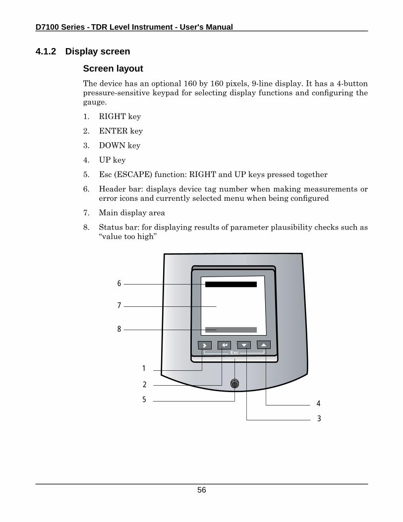
Screen layout
The device has an optional 160 by 160 pixels, 9-line display. It has a 4-button pressure-sensitive keypad for selecting display functions and configuring the gauge.
1. RIGHT key
2. ENTER key
3. DOWN key
4. UP key
5. Esc (ESCAPE) function: RIGHT and UP keys pressed together
6. Header bar: displays device tag number when making measurements or error icons and currently selected menu when being configured
7. Main display area
8. Status bar: for displaying results of parameter plausibility checks such as “value too high”
1
2
3
45
Esc
LT 12345Level
16.345 m
L
6
7
8
Operation
57
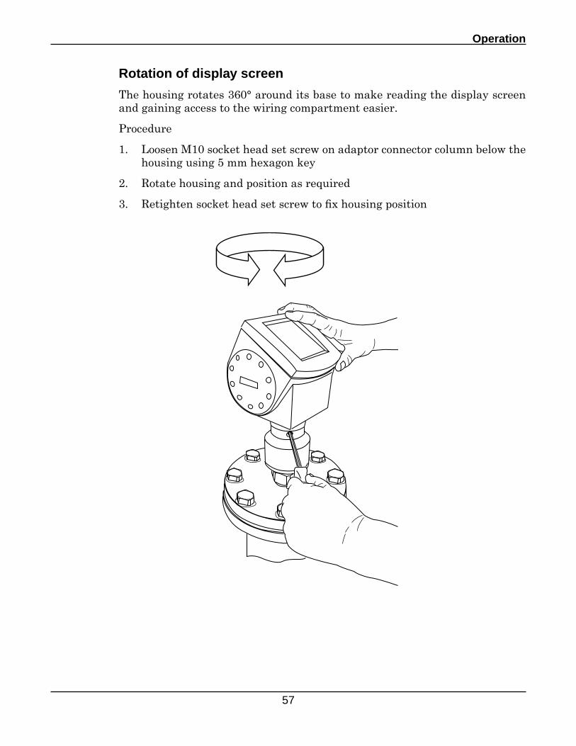
Rotation of display screen
The housing rotates 360° around its base to make reading the display screen and gaining access to the wiring compartment easier.
Procedure
1. Loosen M10 socket head set screw on adaptor connector column below the housing using 5 mm hexagon key
2. Rotate housing and position as required
3. Retighten socket head set screw to fix housing position
D7100 Series - TDR Level Instrument - User's Manual
58
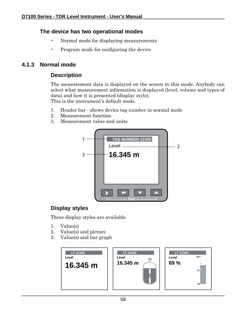
The device has two operational modes
• Normal mode for displaying measurements
• Program mode for configuring the device
4.1.3 Normal mode
Description
The measurement data is displayed on the screen in this mode. Anybody can select what measurement information is displayed (level, volume and types of data) and how it is presented (display style).This is the instrument’s default mode.
1. Header bar - shows device tag number in normal mode2. Measurement function3. Measurement value and units
Display styles
Three display styles are available
1. Value(s)2. Value(s) and picture3. Value(s) and bar graph
2
Esc
TAG NUMBER 12345
Level
16.345 m
1
3
LT 12345Level
16.345 m
LT 12345Level
69 %100
50
0%
LT 12345Level
16.345 m
L
Operation
59
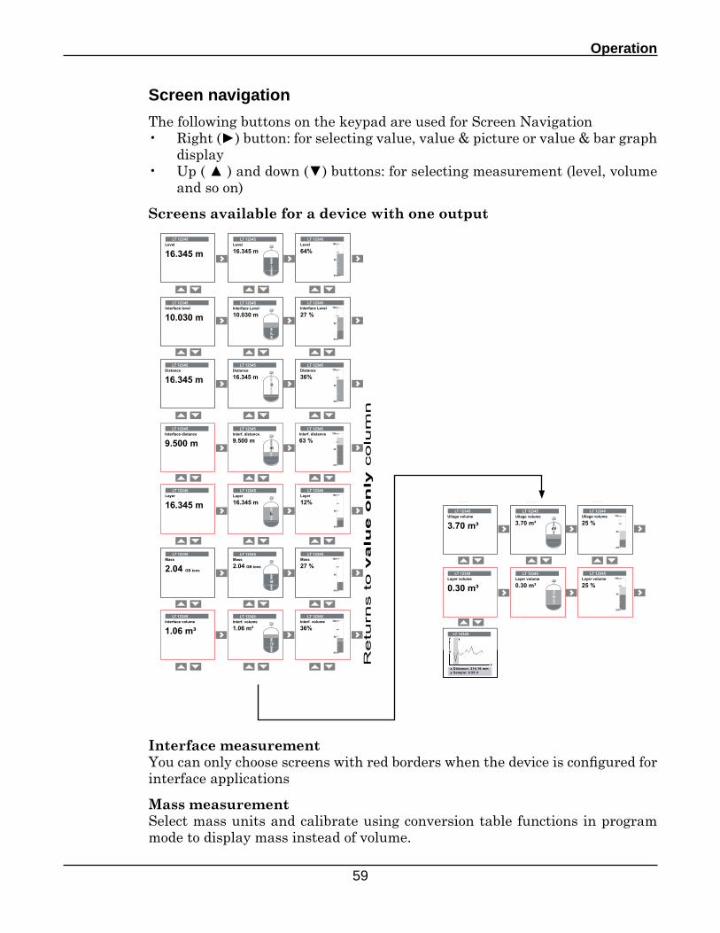
Screen navigation
The following buttons on the keypad are used for Screen Navigation• Right (►) button: for selecting value, value & picture or value & bar graph
display• Up ( ▲ ) and down (▼) buttons: for selecting measurement (level, volume
and so on)
Screens available for a device with one output
Interface measurementYou can only choose screens with red borders when the device is configured for interface applications
Mass measurementSelect mass units and calibrate using conversion table functions in program mode to display mass instead of volume.
D7100 Series - TDR Level Instrument - User's Manual
60
LT 12345Level
16.345 mInterface level
16.345 m
LT 12345Level
16.345 mInterface level
16.345 m
LT 12345Level
45%Interface Level
27 %
LT 12345Distance
16.345 mInterf. distance
9.500 m
LT 12345Distance
16.345 mInterface distance
9.500 m
LT 12345Distance
36%Interf. distance
63 %
LT 12345Layer
16.345 m
LT 12345Layer
16.345 m
LT 12345Layer
12%100
50
0%
LT 12345Volume
2.04 m‡Interf. volume
1.06 m‡
LT 12345Volume
2.04 m‡Interface volume
1.06 m‡
LT 12345Volume
27 %Interf. volume
36%iL
100
50
0%
LT 12345Ullage volume
3.70 m‡D
LT 12345Ullage volume
3.70 m‡
LT 12345Ullage volume
25 %100
50
0%
L
LT 12345Layer volume
0.30 m‡
LT 12345Layer volume
0.30 m‡
LT 12345Layer volume
25 %100
50
0%
L
LT 12345
x Distance: 214.16 mmy Sample: 0.55 V
y
x
0
Retu
rns t
o v
alu
e o
nly
co
lum
n
100
50
0%
iD
iLL
D
100
50
0%
L
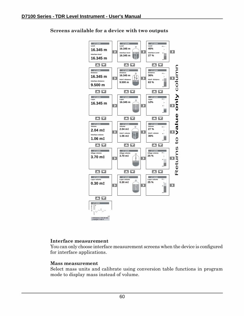
Interface measurementYou can only choose interface measurement screens when the device is configured for interface applications.
Mass measurementSelect mass units and calibrate using conversion table functions in program mode to display mass instead of volume.
Screens available for a device with two outputs
Operation
61
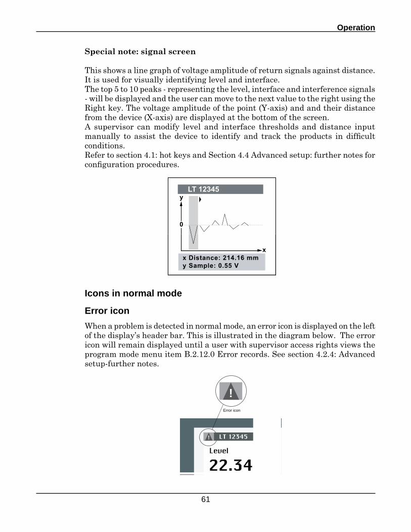
Special note: signal screen
This shows a line graph of voltage amplitude of return signals against distance. It is used for visually identifying level and interface.The top 5 to 10 peaks - representing the level, interface and interference signals - will be displayed and the user can move to the next value to the right using the Right key. The voltage amplitude of the point (Y-axis) and and their distance from the device (X-axis) are displayed at the bottom of the screen.A supervisor can modify level and interface thresholds and distance input manually to assist the device to identify and track the products in difficult conditions.Refer to section 4.1: hot keys and Section 4.4 Advanced setup: further notes for configuration procedures.
Icons in normal mode
Error icon
When a problem is detected in normal mode, an error icon is displayed on the left of the display’s header bar. This is illustrated in the diagram below. The error icon will remain displayed until a user with supervisor access rights views the program mode menu item B.2.12.0 Error records. See section 4.2.4: Advanced setup-further notes.
!
!Error icon
D7100 Series - TDR Level Instrument - User's Manual
62
1
2
3
45
Esc
LT 12345Level
16.345 m
L
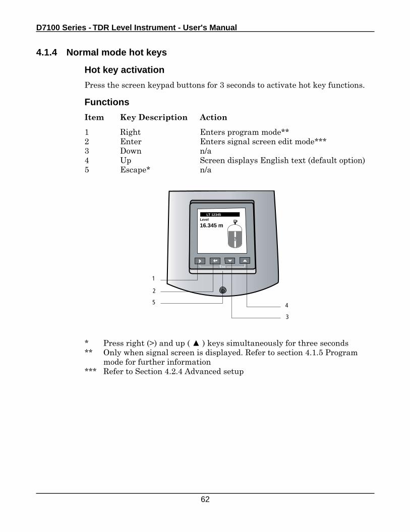
4.1.4 Normal mode hot keys
Hot key activation
Press the screen keypad buttons for 3 seconds to activate hot key functions.
Functions
Item Key Description Action
1 Right Enters program mode** 2 Enter Enters signal screen edit mode*** 3 Down n/a 4 Up Screen displays English text (default option)5 Escape* n/a
* Press right (>) and up ( ▲ ) keys simultaneously for three seconds** Only when signal screen is displayed. Refer to section 4.1.5 Program mode for further information*** Refer to Section 4.2.4 Advanced setup
Operation
63
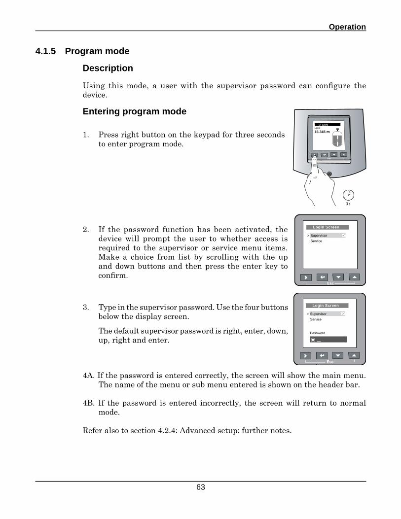
4.1.5 Program mode
Description
Using this mode, a user with the supervisor password can configure the device.
Entering program mode
Esc
LT 12345Level
16.345 m
L
3 s
2. If the password function has been activated, the device will prompt the user to whether access is required to the supervisor or service menu items. Make a choice from list by scrolling with the up and down buttons and then press the enter key to confirm.
Esc
Login Screen
Supervisor
Service
>
1. Press right button on the keypad for three seconds to enter program mode.
3. Type in the supervisor password. Use the four buttons below the display screen.
The default supervisor password is right, enter, down, up, right and enter.
Esc
Login Screen
Supervisor
Service
>
Password
4A. If the password is entered correctly, the screen will show the main menu. The name of the menu or sub menu entered is shown on the header bar.
4B. If the password is entered incorrectly, the screen will return to normal mode.
Refer also to section 4.2.4: Advanced setup: further notes.
D7100 Series - TDR Level Instrument - User's Manual
64
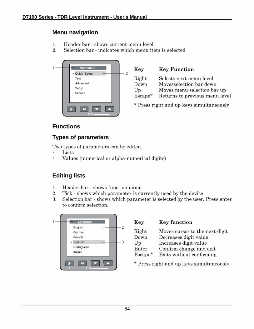
Menu navigation
1. Header bar - shows current menu level2. Selection bar - indicates which menu item is selected
Key Key Function
Right Selects next menu levelDown Movesselection bar downUp Moves menu selection bar upEscape* Returns to previous menu level
* Press right and up keys simultaneously
2
Esc
Main Menu
Quick Setup
Test
Advanced
Setup
Service
>
1
Functions
Types of parameters
Two types of parameters can be edited • Lists• Values (numerical or alpha-numerical digits)
Key Key function
Right Moves cursor to the next digitDown Decreases digit valueUp Increases digit valueEnter Confirm change and exitEscape* Exits without confirming
* Press right and up keys simultaneously
Editing lists
1. Header bar - shows function name2. Tick - shows which parameter is currently used by the device3. Selection bar - shows which parameter is selected by the user. Press enter
to confirm selection.
2
Esc
Language
English
German
French
Spanish
Portuguese
Italian
> 3
1
Operation
65
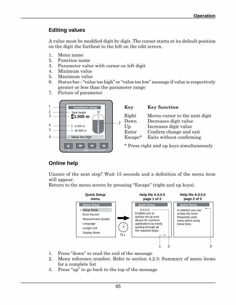
Key Key function
Right Moves cursor to the next digitDown Decreases digit valueUp Increases digit valueEnter Confirm change and exitEscape* Exits without confirming
* Press right and up keys simultaneously
Editing values
A value must be modified digit by digit. The cursor starts at its default position on the digit the furthest to the left on the edit screen.
1. Menu name2. Function name3. Parameter value with cursor on left digit4. Minimum value5. Maximum value6. Status bar - “value too high” or “value too low” message if value is respectively
greater or less than the parameter range7. Picture of parameter
123
45
6
7
Esc
Installation Setup
Tank height
41.000 m
0.200 m
40.000 m
H
Value too high
Online help
Unsure of the next step? Wait 15 seconds and a definition of the menu item will appear.Return to the menu screen by pressing “Escape” (right and up keys).
1. Press “down” to read the end of the message2. Menu reference number. Refer to section 4.2.3: Summary of menu items
for a complete list3. Press “up” to go back to the top of the message
Quick Setup
Setup Mode
Error Record
Measurement Quality
Language
Length Unit
Display Mode
>
15 s
A.0.0.0Enables you toquickly set up your device for commonapplications by easily guiding through all the required steps.
Quick Setup
In addition you can invoke the most frequently used menu items using these links.
Quick Setup
Help file A.0.0.0page 1 of 2
Help file A.0.0.0page 2 of 2
Quick Setupmenu
1 32
D7100 Series - TDR Level Instrument - User's Manual
66
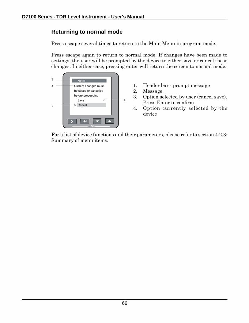
Returning to normal mode
Press escape several times to return to the Main Menu in program mode.
Press escape again to return to normal mode. If changes have been made to settings, the user will be prompted by the device to either save or cancel these changes. In either case, pressing enter will return the screen to normal mode.
1. Header bar - prompt message2. Message3. Option selected by user (cancel save). Press Enter to confirm4. Option currently selected by the
device
For a list of device functions and their parameters, please refer to section 4.2.3: Summary of menu items.
12
43
Esc
Note:
Current changes must
be saved or cancelled
before proceeding
Save
> Cancel
Operation
67
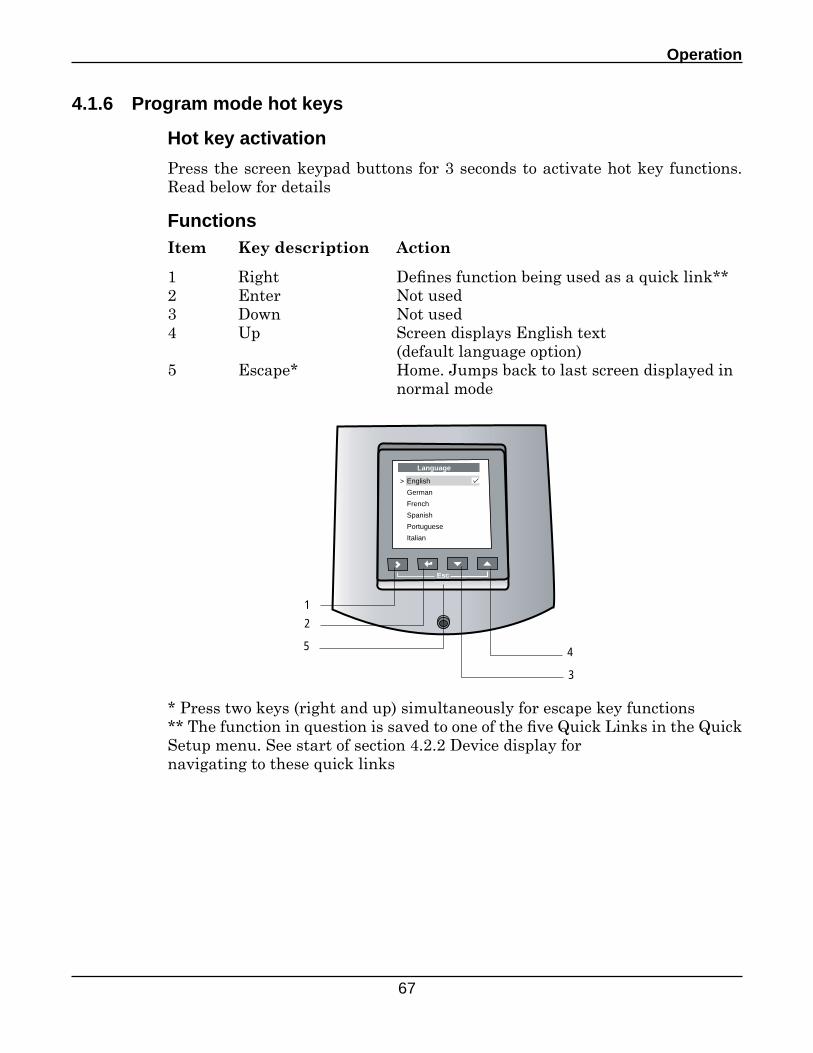
4.1.6 Program mode hot keys
Hot key activation
Press the screen keypad buttons for 3 seconds to activate hot key functions. Read below for details
Functions
2
3
45
1
Esc
Language
English
German
French
Spanish
Portuguese
Italian
>
Item Key description Action
1 Right Defines function being used as a quick link**2 Enter Not used3 Down Not used4 Up Screen displays English text (default language option)5 Escape* Home. Jumps back to last screen displayed in normal mode
* Press two keys (right and up) simultaneously for escape key functions** The function in question is saved to one of the five Quick Links in the Quick Setup menu. See start of section 4.2.2 Device display fornavigating to these quick links
D7100 Series - TDR Level Instrument - User's Manual
68
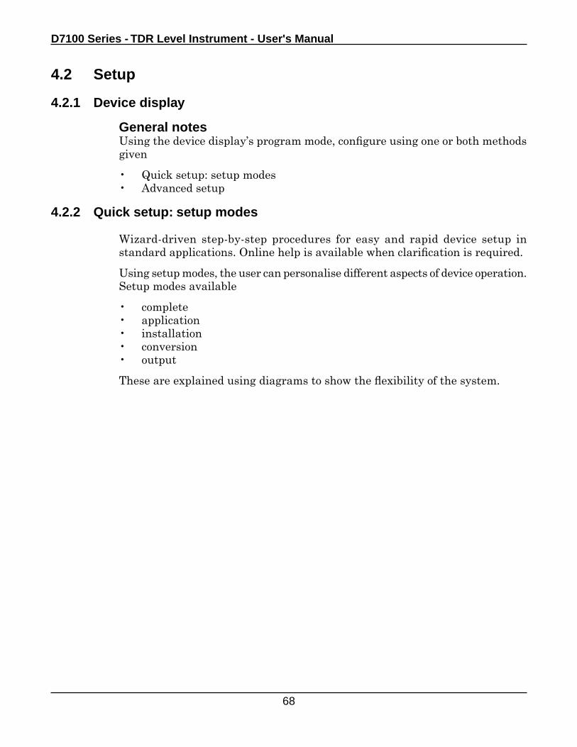
4.2 Setup
4.2.1 Device display
General notesUsing the device display’s program mode, configure using one or both methods given
• Quick setup: setup modes• Advanced setup
4.2.2 Quick setup: setup modes
Wizard-driven step-by-step procedures for easy and rapid device setup in standard applications. Online help is available when clarification is required.
Using setup modes, the user can personalise different aspects of device operation. Setup modes available
• complete• application• installation• conversion• output
These are explained using diagrams to show the flexibility of the system.
Operation
69
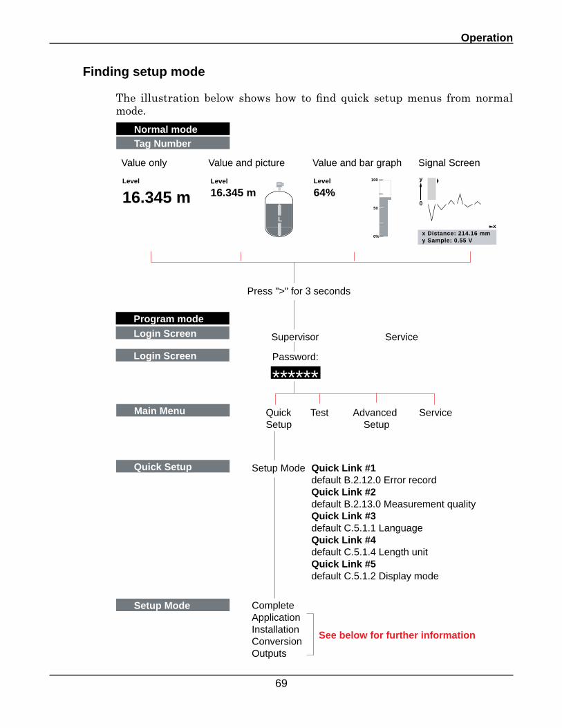
Finding setup mode
The illustration below shows how to find quick setup menus from normal mode.
Normal mode
Quick Setup
Tag Number
Program mode
Main Menu Quick Test Advanced ServiceSetup Setup
Setup Mode Quick Link #1default B.2.12.0 Error recordQuick Link #2default B.2.13.0 Measurement qualityQuick Link #3default C.5.1.1 LanguageQuick Link #4default C.5.1.4 Length unitQuick Link #5default C.5.1.2 Display mode
Setup Mode CompleteApplicationInstallationConversionOutputs
See below for further information
Login Screen Supervisor Service
Login Screen Password:
******
Level
16.345 m
L
Level
16.345 mLevel
64%100
50
0%x Distance: 214.16 mmy Sample: 0.55 V
y
x
0
Value only Value and picture Value and bar graph Signal Screen
Press ">" for 3 seconds
D7100 Series - TDR Level Instrument - User's Manual
70
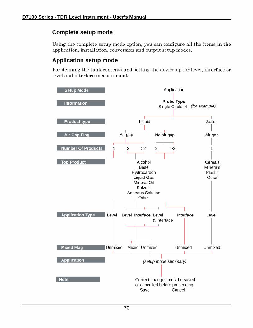
Complete setup mode
Using the complete setup mode option, you can configure all the items in the application, installation, conversion and output setup modes.
Application setup mode
For defining the tank contents and setting the device up for level, interface or level and interface measurement.
Setup Mode Application
Product type Liquid
Information Probe TypeSingle Cable 4
Solid
Number Of Products
No air gap Air gapAir Gap Flag Air gap
1 2 >2 2 >2 1
(for example)
Top Product AlcoholBase
HydrocarbonLiquid GasMineral Oil
SolventAqueous Solution
Other
CerealsMineralsPlasticOther
Application Type
Mixed Flag
Level Level Interface Level Interface Level & interface
Unmixed Mixed Unmixed Unmixed Unmixed
Application (setup mode summary)
Note: Current changes must be saved or cancelled before proceeding Save Cancel
Operation
71
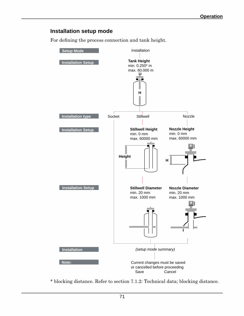
Installation setup mode
For defining the process connection and tank height.
Setup Mode Installation
Installation type Socket
Installation Setup Tank Heightmin. 0.250* mmax. 60.000 m
Stillwell
Installation Setup
Installation Setup
Installation
Nozzle
(setup mode summary)
H
Height
Stillwell Heightmin. 0 mmmax. 60000 mm
Stillwell Diametermin. 20 mmmax. 1000 mm
Nozzle Heightmin. 0 mmmax. 60000 mm
Nozzle Diametermin. 20 mmmax. 1000 mm
H
Note: Current changes must be saved or cancelled before proceeding Save Cancel
* blocking distance. Refer to section 7.1.2: Technical data; blocking distance.
D7100 Series - TDR Level Instrument - User's Manual
72
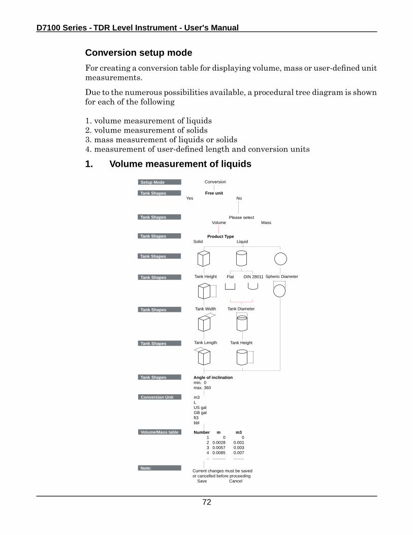
Conversion setup mode
For creating a conversion table for displaying volume, mass or user-defined unit measurements.
Due to the numerous possibilities available, a procedural tree diagram is shown for each of the following
1. volume measurement of liquids2. volume measurement of solids3. mass measurement of liquids or solids4. measurement of user-defined length and conversion units
Setup Mode Conversion
Tank Shapes
Tank Shapes Free unitYes No
Tank Shapes
Please selectVolume Mass
Product TypeSolid Liquid
Tank Shapes
Tank Shapes Tank Height
Tank Diameter
Spheric Diameter
Tank Shapes Tank Width
Tank HeightTank Shapes Tank Length
Flat DIN 28011
Tank Shapes Angle of inclinationmin. 0max. 360
Conversion Unit m3LUS galGB galft3bbl
Volume/Mass table Number m m3 1 0 0 2 0.0028 0.001 3 0.0057 0.003 4 0.0085 0.007 .. ........... .........
Note:Current changes must be saved or cancelled before proceeding Save Cancel
1. Volume measurement of liquids
Operation
73
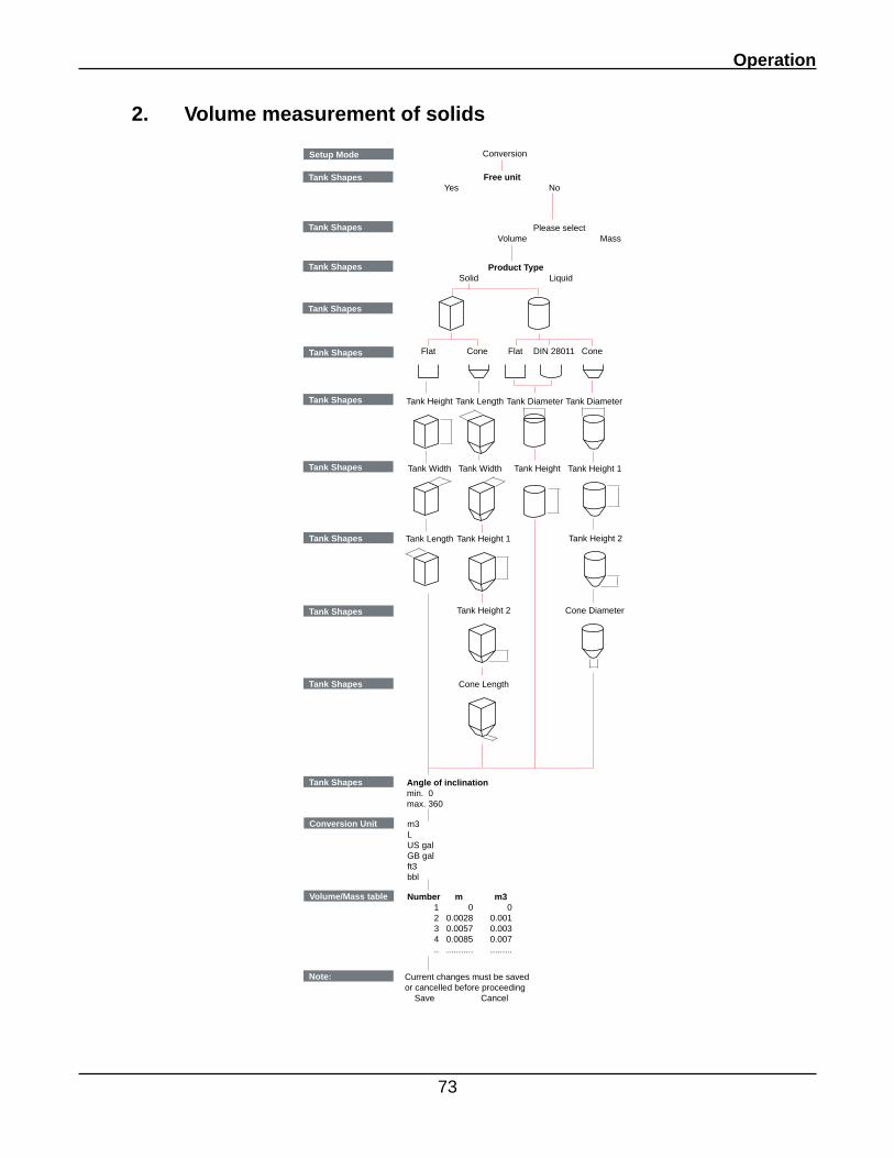
2. Volume measurement of solids
Setup Mode Conversion
Tank Shapes
Tank Shapes Free unitYes No
Tank Shapes
Please selectVolume Mass
Product TypeSolid Liquid
Tank Shapes
Tank Shapes
Tank Height Tank Diameter
Tank Shapes
Tank Width Tank Height
Tank Length
Flat DIN 28011
Tank Shapes Angle of inclinationmin. 0max. 360
Conversion Unit m3LUS galGB galft3bbl
Volume/Mass table Number m m3 1 0 0 2 0.0028 0.001 3 0.0057 0.003 4 0.0085 0.007 .. ........... .........
Note: Current changes must be saved or cancelled before proceeding Save Cancel
ConeFlat
Tank Shapes
Tank Shapes Tank Length Tank Diameter
Tank Shapes
Tank Shapes
Cone
Tank Width
Tank Height 1
Tank Height 2
Cone Length
Tank Height 1
Tank Height 2
Cone Diameter
D7100 Series - TDR Level Instrument - User's Manual
74
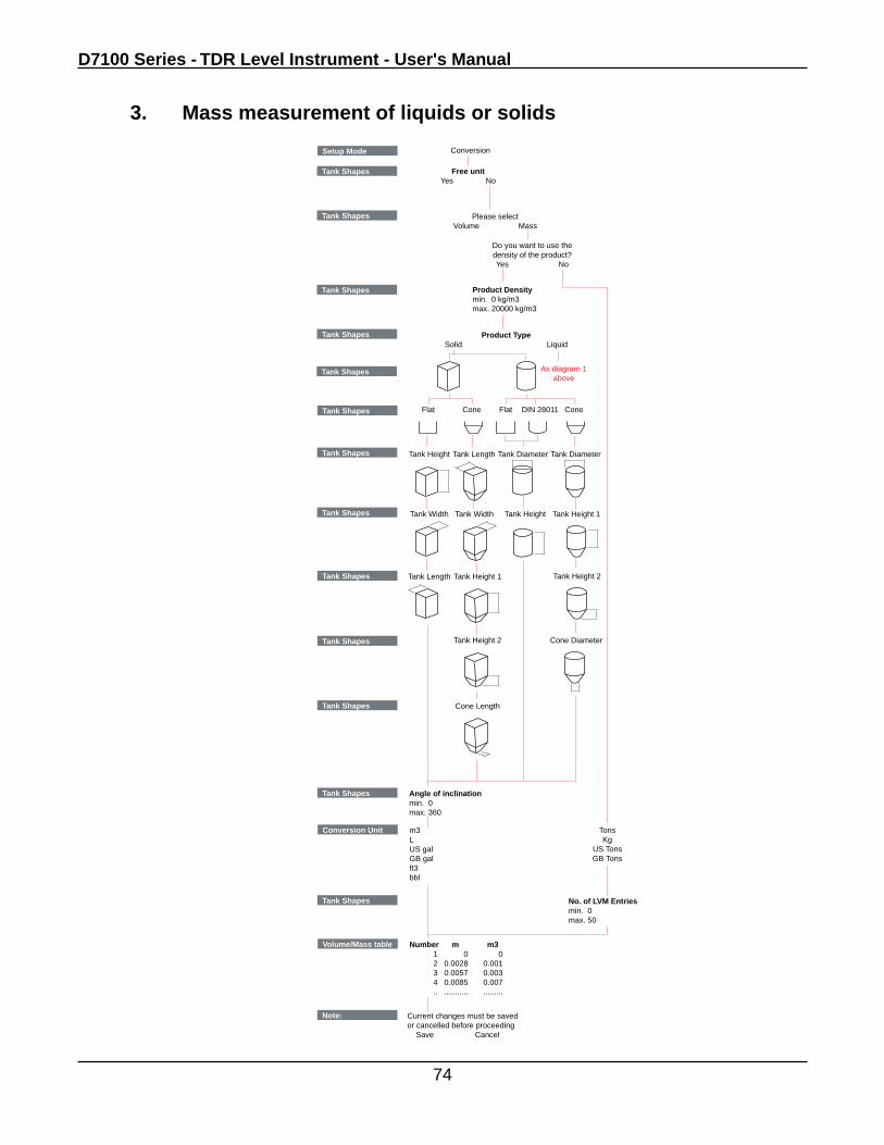
3. Mass measurement of liquids or solids
Setup Mode Conversion
Tank Shapes
Tank Shapes Free unitYes No
Tank Shapes
Please selectVolume Mass
Product TypeSolid Liquid
Tank Shapes
Tank Shapes
Tank Height Tank Diameter
Tank Shapes
Tank Width Tank Height
Tank Length
Flat DIN 28011
Tank Shapes Angle of inclinationmin. 0max. 360
Conversion Unit m3LUS galGB galft3bbl
Volume/Mass table Number m m3 1 0 0 2 0.0028 0.001 3 0.0057 0.003 4 0.0085 0.007 .. ........... .........
Note: Current changes must be saved or cancelled before proceeding Save Cancel
ConeFlat
Tank Shapes
Tank Shapes Tank Length Tank Diameter
Tank Shapes
Tank Shapes
Tank Shapes
TonsKg
US TonsGB Tons
No. of LVM Entriesmin. 0max. 50
Tank Shapes
As diagram 1above
Cone
Tank Width
Tank Height 1
Tank Height 2
Cone Length
Tank Height 1
Tank Height 2
Cone Diameter
Do you want to use thedensity of the product?Yes No
Product Densitymin. 0 kg/m3max. 20000 kg/m3
Operation
75
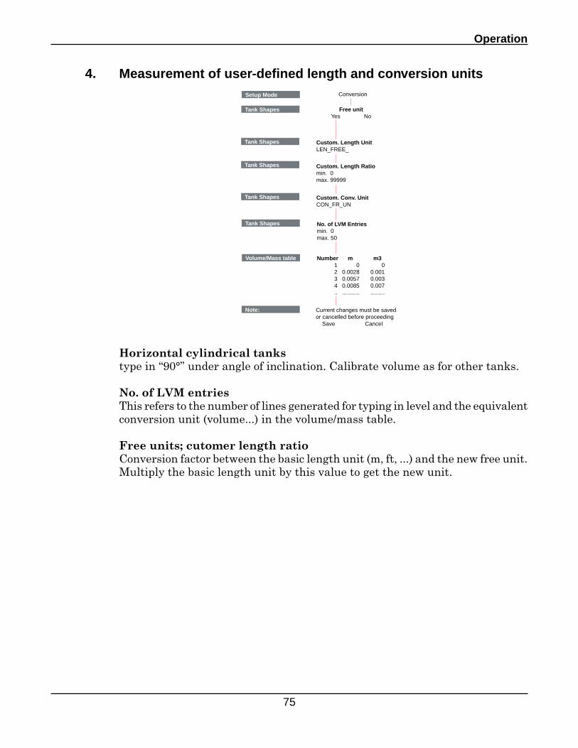
4. Measurement of user-defined length and conversion unitsSetup Mode Conversion
Tank Shapes Free unitYes No
Volume/Mass table Number m m3 1 0 0 2 0.0028 0.001 3 0.0057 0.003 4 0.0085 0.007 .. ........... .........
Note: Current changes must be saved or cancelled before proceeding Save Cancel
Tank Shapes Custom. Length UnitLEN_FREE_
Tank Shapes Custom. Length Ratiomin. 0max. 99999
Tank Shapes Custom. Conv. UnitCON_FR_UN
Tank Shapes No. of LVM Entriesmin. 0max. 50
Horizontal cylindrical tankstype in “90°” under angle of inclination. Calibrate volume as for other tanks.
No. of LVM entriesThis refers to the number of lines generated for typing in level and the equivalent conversion unit (volume...) in the volume/mass table.
Free units; cutomer length ratioConversion factor between the basic length unit (m, ft, ...) and the new free unit. Multiply the basic length unit by this value to get the new unit.
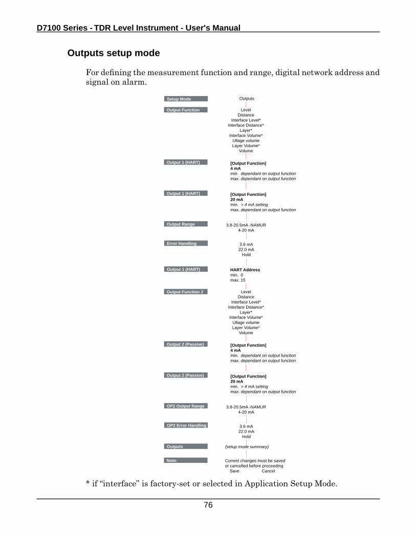
D7100 Series - TDR Level Instrument - User's Manual
76
Outputs setup mode
For defining the measurement function and range, digital network address and signal on alarm.
Setup Mode Outputs
Output Function LevelDistance
Interface Level*Interface Distance*
Layer*Interface Volume*
Ullage volumeLayer Volume*
Volume
Output 1 (HART) [Output Function]4 mAmin. dependant on output functionmax. dependant on output function
Output 1 (HART) [Output Function]20 mAmin. > 4 mA settingmax. dependant on output function
Output Range 3.8-20.5mA -NAMUR4-20 mA
Error Handling 3.6 mA22.0 mA
Hold
Output 1 (HART) HART Addressmin. 0max. 15
Output Function 2 LevelDistance
Interface Level*Interface Distance*
Layer*Interface Volume*
Ullage volumeLayer Volume*
Volume
Output 2 (Passive) [Output Function]4 mAmin. dependant on output functionmax. dependant on output function
Output 2 (Passive) [Output Function]20 mAmin. > 4 mA settingmax. dependant on output function
OP2 Output Range 3.8-20.5mA -NAMUR4-20 mA
OP2 Error Handling 3.6 mA22.0 mA
Hold
(setup mode summary)Outputs
Note: Current changes must be saved or cancelled before proceeding Save Cancel
* if “interface” is factory-set or selected in Application Setup Mode.
Operation
77
Displaying volume measurements
Select a volume output function.
Advanced setup menu
Using this menu, you can modify indivdual functions. These functions are grouped under
• Installation setup• I/O• Output 1 (HART)• Output 2 (Passive)• Device Setup• Reset
Refer to section 4.2.3: Summary of user items for a description of advanced setup menu items.Functions are explained further in section 4.2.4 Advanced setup: further notes.
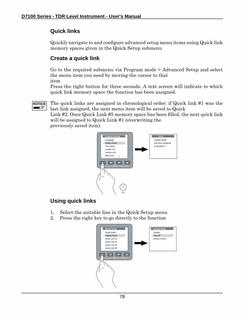
D7100 Series - TDR Level Instrument - User's Manual
78
Using quick links
1. Select the suitable line in the Quick Setup menu2. Press the right key to go directly to the function
Quick links
Quickly navigate to and configure advanced setup menu items using Quick link memory spaces given in the Quick Setup submenu
Create a quick link
Go to the required submenu via Program mode > Advanced Setup and select the menu item you need by moving the cursor to thatitemPress the right button for three seconds. A text screen will indicate to which quick link memory space the function has been assigned.
The quick links are assigned in chronological order: if Quick link #1 was the last link assigned, the next menu item will be saved to QuickLink #2. Once Quick Link #5 memory space has been filled, the next quick link will be assigned to Quick Link #1 (overwriting thepreviously saved item).
Esc
Display Settings
Language
Display Mode
Time Delay
Length Unit
Volume Unit
Mass Unit
>
3 s
Note:
Display Mode
has been assigned
to quicklink 1
Esc
Quick Setup
Setup Mode
Display Mode
Quick Link #2
Quick Link #3
Quick Link #4
Quick Link #5
>
Display Mode
Disable
Auto-off
Default Screen
>
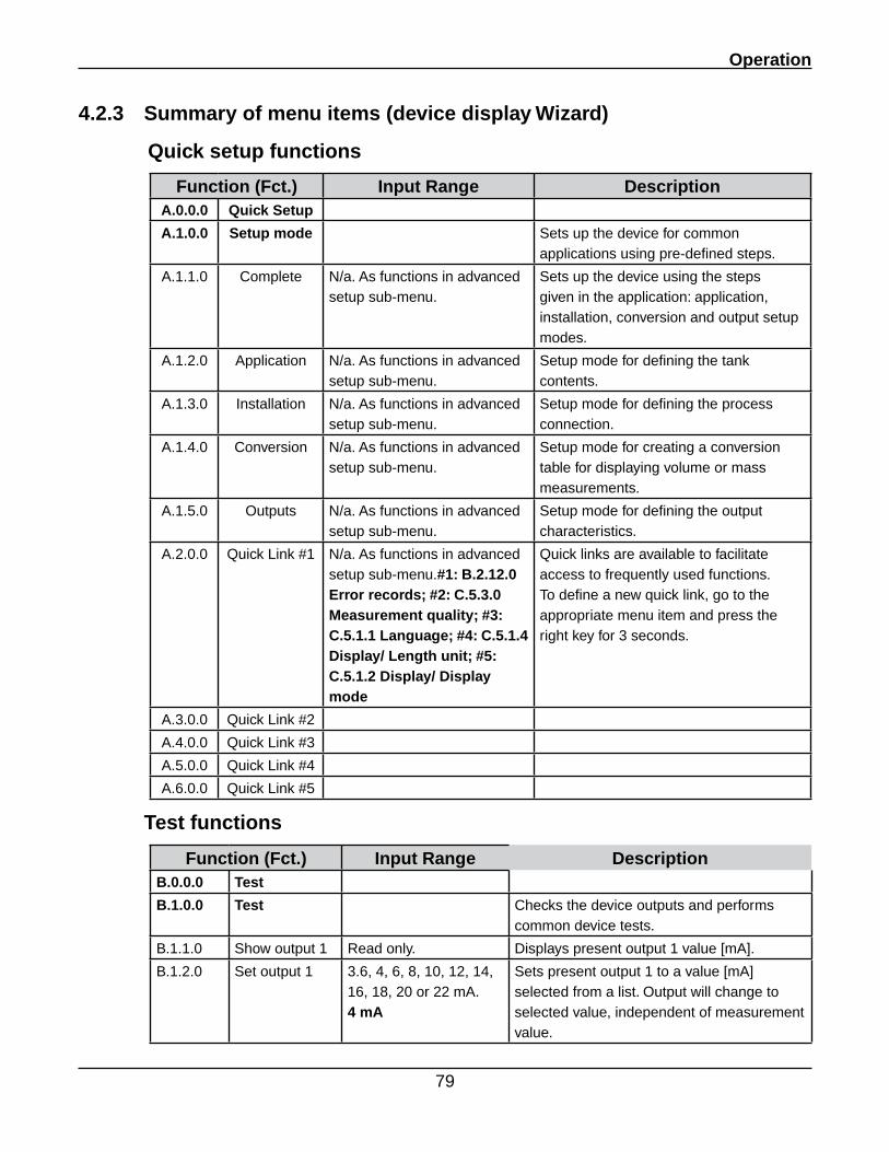
Operation
79
4.2.3 Summary of menu items (device display Wizard)
Quick setup functions
Function (Fct.) Input Range DescriptionA.0.0.0 Quick Setup
A.1.0.0 Setup mode Sets up the device for common applications using pre-defined steps.
A.1.1.0 Complete N/a. As functions in advanced setup sub-menu.
Sets up the device using the steps given in the application: application, installation, conversion and output setup modes.
A.1.2.0 Application N/a. As functions in advanced setup sub-menu.
Setup mode for defining the tank contents.
A.1.3.0 Installation N/a. As functions in advanced setup sub-menu.
Setup mode for defining the process connection.
A.1.4.0 Conversion N/a. As functions in advanced setup sub-menu.
Setup mode for creating a conversion table for displaying volume or mass measurements.
A.1.5.0 Outputs N/a. As functions in advanced setup sub-menu.
Setup mode for defining the output characteristics.
A.2.0.0 Quick Link #1 N/a. As functions in advanced setup sub-menu.#1: B.2.12.0 Error records; #2: C.5.3.0 Measurement quality; #3: C.5.1.1 Language; #4: C.5.1.4 Display/ Length unit; #5: C.5.1.2 Display/ Display mode
Quick links are available to facilitate access to frequently used functions. To define a new quick link, go to the appropriate menu item and press the right key for 3 seconds.
A.3.0.0 Quick Link #2
A.4.0.0 Quick Link #3
A.5.0.0 Quick Link #4
A.6.0.0 Quick Link #5
Test functions
Function (Fct.) Input Range DescriptionB.0.0.0 Test
B.1.0.0 Test Checks the device outputs and performs common device tests.
B.1.1.0 Show output 1 Read only. Displays present output 1 value [mA].
B.1.2.0 Set output 1 3.6, 4, 6, 8, 10, 12, 14, 16, 18, 20 or 22 mA. 4 mA
Sets present output 1 to a value [mA] selected from a list. Output will change to selected value, independent of measurement value.
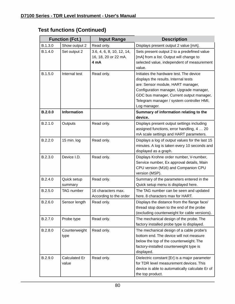
D7100 Series - TDR Level Instrument - User's Manual
80
Function (Fct.) Input Range DescriptionB.1.3.0 Show output 2 Read only. Displays present output 2 value [mA].
B.1.4.0 Set output 2 3.6, 4, 6, 8, 10, 12, 14, 16, 18, 20 or 22 mA. 4 mA
Sets present output 2 to a predefined value [mA] from a list. Output will change to selected value, independent of measurement value.
B.1.5.0 Internal test Read only. Initiates the hardware test. The device displays the results. Internal tests are: Sensor module, HART manager, Configuration manager, Upgrade manager, GDC bus manager, Current output manager, Telegram manager / system controller HMI, Log manager.
B.2.0.0 Information Summary of information relating to the device.
B.2.1.0 Outputs Read only. Displays present output settings including assigned functions, error handling, 4 … 20 mA scale settings and HART parameters.
B.2.2.0 15 min. log Read only. Displays a log of output values for the last 15 minutes. A log is taken every 10 seconds and displayed as a graph.
B.2.3.0 Device I.D. Read only. Displays Krohne order number, V-number, Service number, Ex approval details, Main CPU version (M16) and Companion CPU version (MSP).
B.2.4.0 Quick setup summary
Read only. Summary of the parameters entered in the Quick setup menu is displayed here.
B.2.5.0 TAG number 16 characters max. According to the order
The TAG number can be seen and updated here. 8 characters max for HART.
B.2.6.0 Sensor length Read only. Displays the distance from the flange face/thread stop down to the end of the probe (excluding counterweight for cable versions).
B.2.7.0 Probe type Read only. The mechanical design of the probe. The factory installed probe type is displayed.
B.2.8.0 Counterweight type
Read only. The mechanical design of a cable probe’s bottom end. The device will not measure below the top of the counterweight. The factory-installed counterweight type is displayed.
B.2.9.0 Calculated Er value
Read only. Dielectric constant [Er] is a major parameter for TDR level measurement devices. This device is able to automatically calculate Er of the top product.
Test functions (Continued)
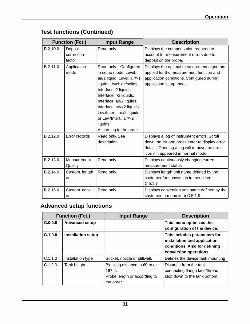
Operation
81
Test functions (Continued)
Function (Fct.) Input Range DescriptionB.2.10.0 Deposit
correction factor
Read only. Displays the compensation required to account for measurement errors due to deposit on the probe.
B.2.11.0 Application mode
Read only…Configured in setup mode: Level: air/1 liquid, Level: air/>1 liquid, Level: air/solids, Interface: 2 liquids, Interface: >2 liquids, Interface: air/2 liquids, Interface: air/>2 liquids, Lev./Interf.: air/2 liquids or Lev./Interf.: air/>2 liquids. According to the order
Displays the optimal measurement algorithm applied for the measurement function and application conditions. Configured during application setup mode.
B.2.12.0 Error records Read only. See description.
Displays a log of instrument errors. Scroll down the list and press enter to display error details. Opening a log will remove the error icon if it appeared in normal mode.
B.2.13.0 Measurement Quality
Read only. Displays continuously changing current measurement status.
B.2.14.0 Custom. length unit
Read only. Displays length unit name defined by the customer for conversion in menu item C.5.1.7
B.2.15.0 Custom. conv. unit
Read only. Displays conversion unit name defined by the customer in menu item C.5.1.9.
Advanced setup functions
Function (Fct.) Input Range DescriptionC.0.0.0 Advanced setup This menu optimizes the
configuration of the device.
C.1.0.0 Installation setup This includes parameters for installation and application conditions. Also for defining conversion operations.
C.1.1.0 Installation type Socket, nozzle or stillwell. Defines the device tank mounting
C.1.2.0 Tank height Blocking distance to 60 m or 197 ft.Probe length or according to the order
Distance from the tank connecting flange face/thread stop down to the tank bottom.
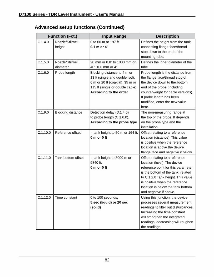
D7100 Series - TDR Level Instrument - User's Manual
82
Function (Fct.) Input Range DescriptionC.1.4.0 Nozzle/Stillwell
height 0 to 60 m or 197 ft.0.1 m or 4”
Defines the height from the tank connecting flange face/thread stop down to the end of the mounting tube.
C.1.5.0 Nozzle/Stillwell diameter
20 mm or 0.8” to 1000 mm or 40”.100 mm or 4”
Defines the inner diameter of the tube
C.1.6.0 Probe length Blocking distance to 4 m or 13 ft (single and double rod), 6 m or 20 ft (coaxial), 35 m or 115 ft (single or double cable).According to the order
Probe length is the distance from the flange face/thread stop of the device down to the bottom end of the probe (including counterweight for cable versions). If probe length has been modified, enter the new value here.
C.1.9.0 Blocking distance Detection delay (D.1.4.0) to probe length (C.1.6.0).According to the probe type
The non-measuring range at the top of the probe. It depends on the probe type and the installation.
C.1.10.0 Reference offset - tank height to 50 m or 164 ft.0 m or 0 ft
Offset relating to a reference location (distance). This value is positive when the reference location is above the device flange face and negative if below.
C.1.11.0 Tank bottom offset - tank height to 3000 m or 9840 ft.0 m or 0 ft
Offset relating to a reference location (level). The device reference point for this parameter is the bottom of the tank, related to C.1.2.0 Tank height. This value is positive when the reference location is below the tank bottom and negative if above.
C.1.12.0 Time constant 0 to 100 seconds.5 sec (liquid) or 20 sec (solid)
Using this function, the device processes several measurement readings to filter out disturbances. Increasing the time constant will smoothen the integrated readings, decreasing will roughen the readings.
Advanced setup functions (Continued)
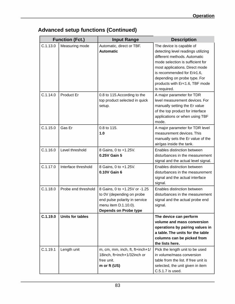
Operation
83
Advanced setup functions (Continued)
Function (Fct.) Input Range DescriptionC.1.13.0 Measuring mode Automatic, direct or TBF.
AutomaticThe device is capable of detecting level readings utilizing different methods. Automatic mode selection is sufficient for most applications. Direct mode is recommended for Er≥1.6, depending on probe type. For products with Er<1.6, TBF mode is required.
C.1.14.0 Product Er 0.8 to 115.According to the top product selected in quick setup.
A major parameter for TDR level measurement devices. For manually setting the Er value of the top product for interface applications or when using TBF mode.
C.1.15.0 Gas Er 0.8 to 115.1.0
A major parameter for TDR level measurement devices. This manually sets the Er value of the air/gas inside the tank.
C.1.16.0 Level threshold 8 Gains, 0 to +1.25V.0.25V Gain 5
Enables distinction between disturbances in the measurement signal and the actual level signal.
C.1.17.0 Interface threshold 8 Gains, 0 to +1.25V.0.10V Gain 6
Enables distinction between disturbances in the measurement signal and the actual interface signal.
C.1.18.0 Probe end threshold 8 Gains, 0 to +1.25V or -1.25 to 0V (depending on probe end pulse polarity in service menu item D.1.10.0).Depends on Probe type
Enables distinction between disturbances in the measurement signal and the actual probe end signal.
C.1.19.0 Units for tables The device can perform volume and mass conversion operations by pairing values in a table. The units for the table columns can be picked from the lists here.
C.1.19.1 Length unit m, cm, mm, inch, ft, ft+inch+1/18inch, ft+inch+1/32inch or free unit.m or ft (US)
Pick the length unit to be used in volume/mass conversion table from the list. If free unit is selected, the unit given in item C.5.1.7 is used.
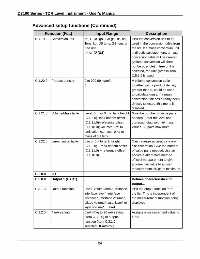
D7100 Series - TDR Level Instrument - User's Manual
84
Advanced setup functions (Continued)
Function (Fct.) Input Range DescriptionC.1.19.2 Conversion unit m³, L, US gal, GB gal, ft³, bbl,
Tons, kg, US tons, GB tons or free unit.m³ or ft³ (US)
Pick the conversion unit to be used in the conversion table from the list. If a mass conversion unit is directly selected here, a mass conversion table will be created (volume conversion will then not be possible). If free unit is selected, the unit given in item C.5.1.9 is used.
C.1.20.0 Product density 0 to 999.99 kg/m³.0
A volume conversion table together with a product density greater than 0, could be used to calculate mass. If a mass conversion unit has already been directly selected, this menu is disabled.
C.1.21.0 Volume/Mass table Level: 0 m or 0 ft to tank height (C.1.2.0)+tank bottom offset (C.1.11.0)+reference offset (C.1.10.0); volume: 0 m³ to tank volume.; mass: 0 kg to mass of full tank.
Give the number of value pairs needed. Enter the level and corresponding volume/ mass values. 50 pairs maximum.
C.1.22.0 Linearisation table 0 m or 0 ft to tank height (C.1.2.0) + tank bottom offset (C.1.11.0) + reference offset (C.1.10.0).
Can increase accuracy via on-site calibration. Give the number of value pairs needed. Use an accurate alternative method of level measurement to give a corrective value to a given measurement. 50 pairs maximum.
C.2.0.0 I/O
C.3.0.0 Output 1 (HART) Defines characteristics of output1.
C.3.1.0 Output function Level, volume/mass, distance, interface level*, interface distance*, interface volume*, ullage volume/mass, layer* or layer volume*. Level
Pick the output function from the list. This is independent of the measurement function being displayed.
C.3.2.0 4 mA setting 0 m/m³/kg to 20 mA setting (item C.3.3.0) of output function (item C.3.1.0) selected. 0 m/m³/kg
Assigns a measurement value to 4 mA
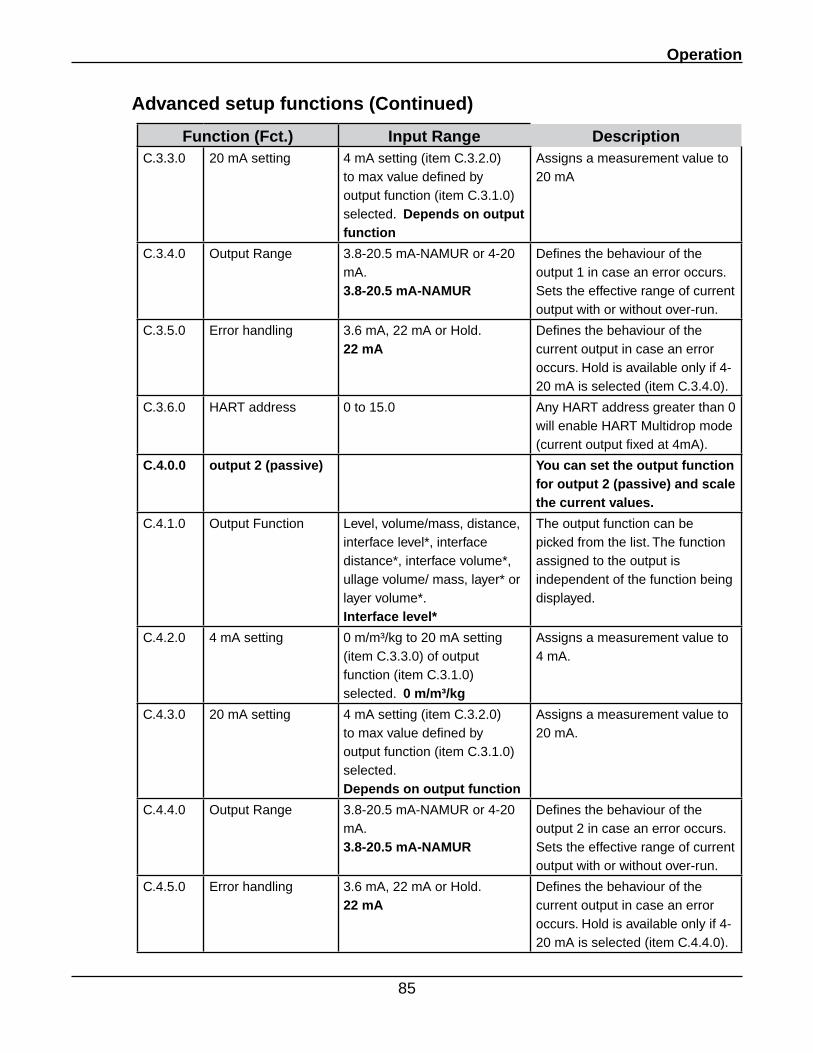
Operation
85
Advanced setup functions (Continued)
Function (Fct.) Input Range DescriptionC.3.3.0 20 mA setting 4 mA setting (item C.3.2.0)
to max value defined by output function (item C.3.1.0) selected. Depends on output function
Assigns a measurement value to 20 mA
C.3.4.0 Output Range 3.8-20.5 mA-NAMUR or 4-20 mA.3.8-20.5 mA-NAMUR
Defines the behaviour of the output 1 in case an error occurs. Sets the effective range of current output with or without over-run.
C.3.5.0 Error handling 3.6 mA, 22 mA or Hold.22 mA
Defines the behaviour of the current output in case an error occurs. Hold is available only if 4-20 mA is selected (item C.3.4.0).
C.3.6.0 HART address 0 to 15.0 Any HART address greater than 0 will enable HART Multidrop mode (current output fixed at 4mA).
C.4.0.0 output 2 (passive) You can set the output function for output 2 (passive) and scale the current values.
C.4.1.0 Output Function Level, volume/mass, distance, interface level*, interface distance*, interface volume*, ullage volume/ mass, layer* or layer volume*. Interface level*
The output function can be picked from the list. The function assigned to the output is independent of the function being displayed.
C.4.2.0 4 mA setting 0 m/m³/kg to 20 mA setting (item C.3.3.0) of output function (item C.3.1.0) selected. 0 m/m³/kg
Assigns a measurement value to 4 mA.
C.4.3.0 20 mA setting 4 mA setting (item C.3.2.0) to max value defined by output function (item C.3.1.0) selected. Depends on output function
Assigns a measurement value to 20 mA.
C.4.4.0 Output Range 3.8-20.5 mA-NAMUR or 4-20 mA.3.8-20.5 mA-NAMUR
Defines the behaviour of the output 2 in case an error occurs. Sets the effective range of current output with or without over-run.
C.4.5.0 Error handling 3.6 mA, 22 mA or Hold.22 mA
Defines the behaviour of the current output in case an error occurs. Hold is available only if 4-20 mA is selected (item C.4.4.0).
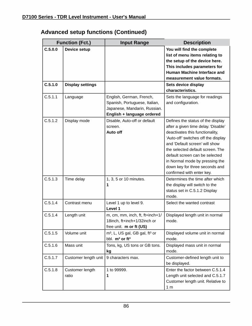
D7100 Series - TDR Level Instrument - User's Manual
86
Function (Fct.) Input Range DescriptionC.5.0.0 Device setup You will find the complete
list of menu items relating to the setup of the device here. This includes parameters for Human Machine Interface and measurement value formats.
C.5.1.0 Display settings Sets device display characteristics.
C.5.1.1 Language English, German, French, Spanish, Portuguese, Italian, Japanese, Mandarin, Russian.English + language ordered
Sets the language for readings and configuration.
C.5.1.2 Display mode Disable, Auto-off or default screen.Auto off
Defines the status of the display after a given time delay. ‘Disable’ deactivates this functionality, ‘Auto-off’ switches off the display and ‘Default screen’ will show the selected default screen. The default screen can be selected in Normal mode by pressing the down key for three seconds and confirmed with enter key.
C.5.1.3 Time delay 1, 3, 5 or 10 minutes.1
Determines the time after which the display will switch to the status set in C.5.1.2 Display mode.
C.5.1.4 Contrast menu Level 1 up to level 9.Level 1
Select the wanted contrast
C.5.1.4 Length unit m, cm, mm, inch, ft, ft+inch+1/18inch, ft+inch+1/32inch or free unit. m or ft (US)
Displayed length unit in normal mode.
C.5.1.5 Volume unit m³, L, US gal, GB gal, ft³ or bbl. m³ or ft³
Displayed volume unit in normal mode.
C.5.1.6 Mass unit Tons, kg, US tons or GB tons.kg
Displayed mass unit in normal mode.
C.5.1.7 Customer length unit 9 characters max. Customer-defined length unit to be displayed.
C.5.1.8 Customer length ratio
1 to 99999.1
Enter the factor between C.5.1.4 Length unit selected and C.5.1.7 Customer length unit. Relative to 1 m
Advanced setup functions (Continued)
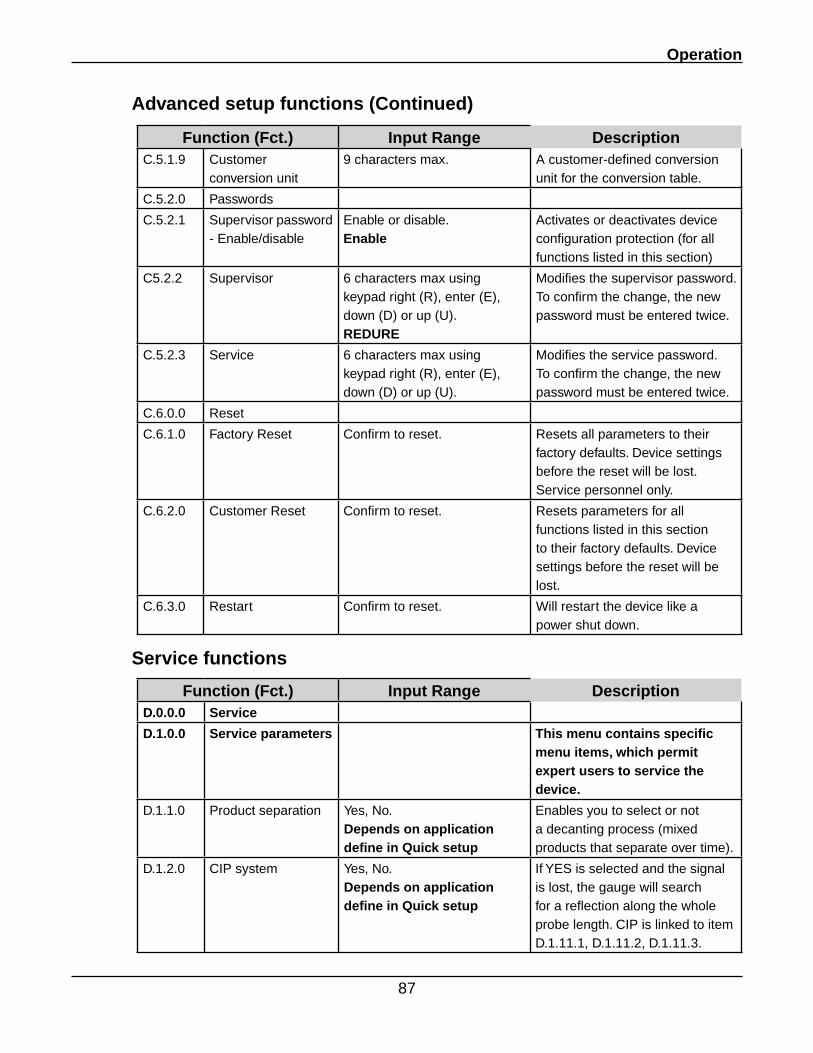
Operation
87
Advanced setup functions (Continued)
Function (Fct.) Input Range DescriptionC.5.1.9 Customer
conversion unit9 characters max. A customer-defined conversion
unit for the conversion table.
C.5.2.0 Passwords
C.5.2.1 Supervisor password - Enable/disable
Enable or disable.Enable
Activates or deactivates device configuration protection (for all functions listed in this section)
C5.2.2 Supervisor 6 characters max using keypad right (R), enter (E), down (D) or up (U).REDURE
Modifies the supervisor password. To confirm the change, the new password must be entered twice.
C.5.2.3 Service 6 characters max using keypad right (R), enter (E), down (D) or up (U).
Modifies the service password. To confirm the change, the new password must be entered twice.
C.6.0.0 Reset
C.6.1.0 Factory Reset Confirm to reset. Resets all parameters to their factory defaults. Device settings before the reset will be lost. Service personnel only.
C.6.2.0 Customer Reset Confirm to reset. Resets parameters for all functions listed in this section to their factory defaults. Device settings before the reset will be lost.
C.6.3.0 Restart Confirm to reset. Will restart the device like a power shut down.
Service functions
Function (Fct.) Input Range DescriptionD.0.0.0 Service
D.1.0.0 Service parameters This menu contains specific menu items, which permit expert users to service the device.
D.1.1.0 Product separation Yes, No. Depends on application define in Quick setup
Enables you to select or not a decanting process (mixed products that separate over time).
D.1.2.0 CIP system Yes, No.Depends on application define in Quick setup
If YES is selected and the signal is lost, the gauge will search for a reflection along the whole probe length. CIP is linked to item D.1.11.1, D.1.11.2, D.1.11.3.
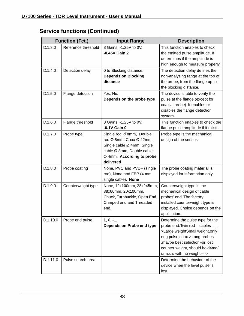
D7100 Series - TDR Level Instrument - User's Manual
88
Function (Fct.) Input Range DescriptionD.1.3.0 Reference threshold 8 Gains, -1.25V to 0V.
-0.45V Gain 2This function enables to check the emitted pulse amplitude. It determines if the amplitude is high enough to measure properly.
D.1.4.0 Detection delay 0 to Blocking distance. Depends on Blocking distance
The detection delay defines the non-analysing range at the top of the probe, from the flange up to the blocking distance.
D.1.5.0 Flange detection Yes, No.Depends on the probe type
The device is able to verify the pulse at the flange (except for coaxial probe). It enables or disables the flange detection system.
D.1.6.0 Flange threshold 8 Gains, -1.25V to 0V.-0.1V Gain 0
This function enables to check the flange pulse amplitude if it exists.
D.1.7.0 Probe type Single rod Ø 8mm, Double rod Ø 8mm, Coax Ø 22mm, Single cable Ø 4mm, Single cable Ø 8mm, Double cable Ø 4mm. According to probe delivered
Probe type is the mechanical design of the sensor.
D.1.8.0 Probe coating None, PVC and PVDF (single rod), None and FEP (4 mm single cable). None
The probe coating material is displayed for information only.
D.1.9.0 Counterweight type None, 12x100mm, 38x245mm, 38x60mm, 20x100mm, Chuck, Turnbuckle, Open End, Crimped end and Threaded end.
Counterweight type is the mechanical design of cable probes’ end. The factory installed counterweight type is displayed. Choice depends on the application.
D.1.10.0 Probe end pulse 1, 0, -1.Depends on Probe end type
Determine the pulse type for the probe end.Twin rod – cables----->Large weightSmall weight,only neg pulse,coax->Long probes ,maybe best selectionFor lost counter weight, should hold4ma/ or rod’s with no weight---->
D.1.11.0 Pulse search area Determine the behaviour of the device when the level pulse is lost.
Service functions (Continued)
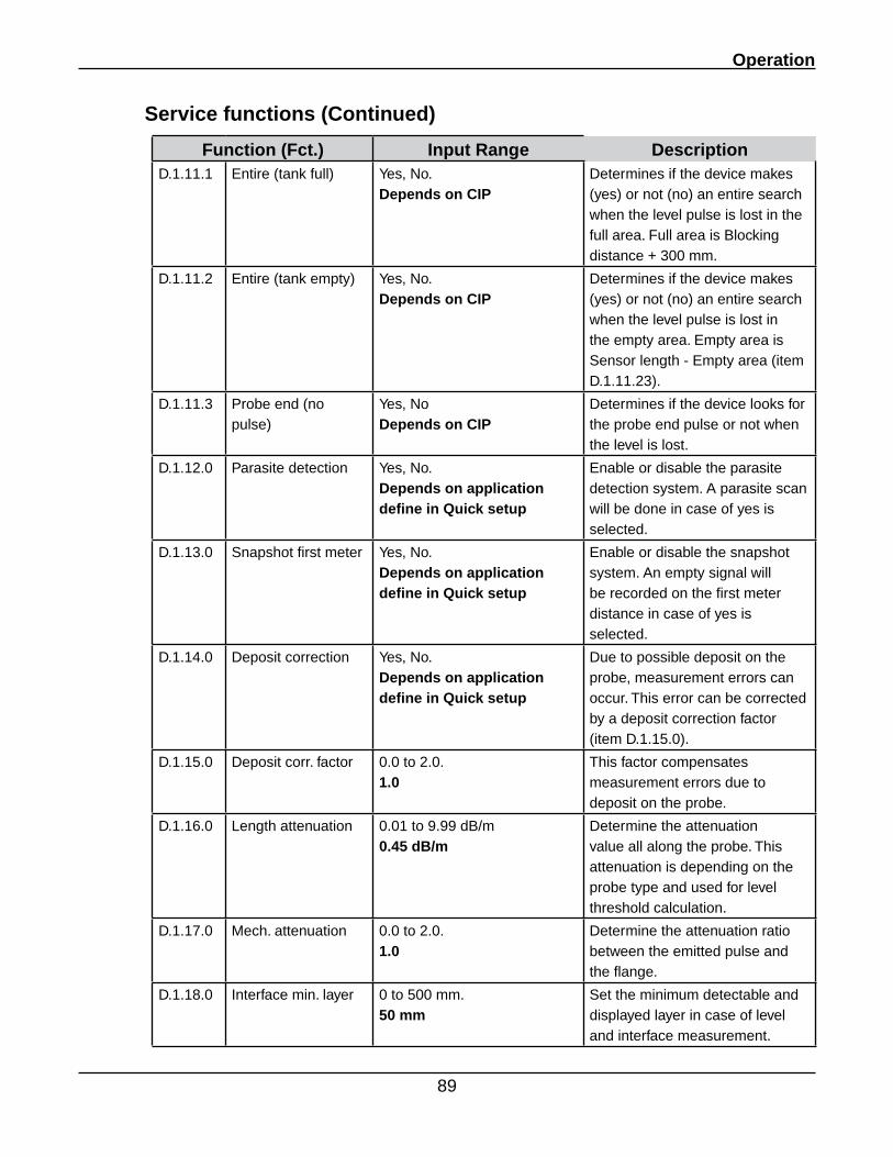
Operation
89
Service functions (Continued)
Function (Fct.) Input Range DescriptionD.1.11.1 Entire (tank full) Yes, No.
Depends on CIPDetermines if the device makes (yes) or not (no) an entire search when the level pulse is lost in the full area. Full area is Blocking distance + 300 mm.
D.1.11.2 Entire (tank empty) Yes, No.Depends on CIP
Determines if the device makes (yes) or not (no) an entire search when the level pulse is lost in the empty area. Empty area is Sensor length - Empty area (item D.1.11.23).
D.1.11.3 Probe end (no pulse)
Yes, NoDepends on CIP
Determines if the device looks for the probe end pulse or not when the level is lost.
D.1.12.0 Parasite detection Yes, No.Depends on application define in Quick setup
Enable or disable the parasite detection system. A parasite scan will be done in case of yes is selected.
D.1.13.0 Snapshot first meter Yes, No.Depends on application define in Quick setup
Enable or disable the snapshot system. An empty signal will be recorded on the first meter distance in case of yes is selected.
D.1.14.0 Deposit correction Yes, No.Depends on application define in Quick setup
Due to possible deposit on the probe, measurement errors can occur. This error can be corrected by a deposit correction factor (item D.1.15.0).
D.1.15.0 Deposit corr. factor 0.0 to 2.0.1.0
This factor compensates measurement errors due to deposit on the probe.
D.1.16.0 Length attenuation 0.01 to 9.99 dB/m 0.45 dB/m
Determine the attenuation value all along the probe. This attenuation is depending on the probe type and used for level threshold calculation.
D.1.17.0 Mech. attenuation 0.0 to 2.0.1.0
Determine the attenuation ratio between the emitted pulse and the flange.
D.1.18.0 Interface min. layer 0 to 500 mm.50 mm
Set the minimum detectable and displayed layer in case of level and interface measurement.
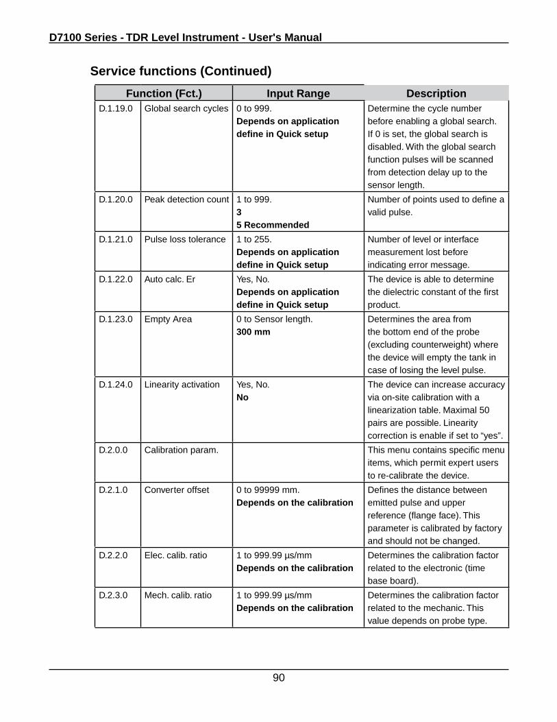
D7100 Series - TDR Level Instrument - User's Manual
90
Function (Fct.) Input Range DescriptionD.1.19.0 Global search cycles 0 to 999.
Depends on application define in Quick setup
Determine the cycle number before enabling a global search. If 0 is set, the global search is disabled. With the global search function pulses will be scanned from detection delay up to the sensor length.
D.1.20.0 Peak detection count 1 to 999.35 Recommended
Number of points used to define a valid pulse.
D.1.21.0 Pulse loss tolerance 1 to 255.Depends on application define in Quick setup
Number of level or interface measurement lost before indicating error message.
D.1.22.0 Auto calc. Er Yes, No.Depends on application define in Quick setup
The device is able to determine the dielectric constant of the first product.
D.1.23.0 Empty Area 0 to Sensor length.300 mm
Determines the area from the bottom end of the probe (excluding counterweight) where the device will empty the tank in case of losing the level pulse.
D.1.24.0 Linearity activation Yes, No.No
The device can increase accuracy via on-site calibration with a linearization table. Maximal 50 pairs are possible. Linearity correction is enable if set to “yes”.
D.2.0.0 Calibration param. This menu contains specific menu items, which permit expert users to re-calibrate the device.
D.2.1.0 Converter offset 0 to 99999 mm.Depends on the calibration
Defines the distance between emitted pulse and upper reference (flange face). This parameter is calibrated by factory and should not be changed.
D.2.2.0 Elec. calib. ratio 1 to 999.99 µs/mmDepends on the calibration
Determines the calibration factor related to the electronic (time base board).
D.2.3.0 Mech. calib. ratio 1 to 999.99 µs/mm Depends on the calibration
Determines the calibration factor related to the mechanic. This value depends on probe type.
Service functions (Continued)
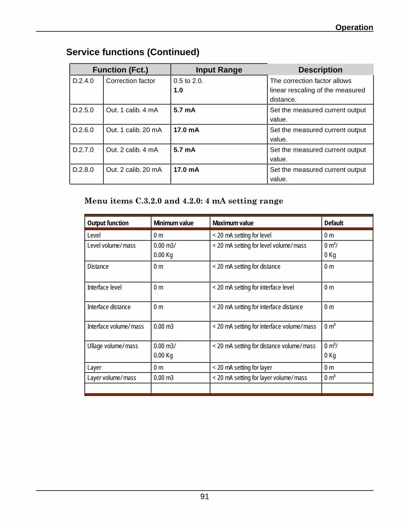
Operation
91
Service functions (Continued)
Function (Fct.) Input Range DescriptionD.2.4.0 Correction factor 0.5 to 2.0.
1.0The correction factor allows linear rescaling of the measured distance.
D.2.5.0 Out. 1 calib. 4 mA 5.7 mA Set the measured current output value.
D.2.6.0 Out. 1 calib. 20 mA 17.0 mA Set the measured current output value.
D.2.7.0 Out. 2 calib. 4 mA 5.7 mA Set the measured current output value.
D.2.8.0 Out. 2 calib. 20 mA 17.0 mA Set the measured current output value.
Menu items C.3.2.0 and 4.2.0: 4 mA setting range
Output function Minimum value Maximum value Default
Level 0 m < 20 mA setting for level 0 mLevel volume/ mass 0.00 m3/
0.00 Kg< 20 mA setting for level volume/ mass 0 m³/
0 KgDistance 0 m < 20 mA setting for distance 0 m
Interface level 0 m < 20 mA setting for interface level 0 m
Interface distance 0 m < 20 mA setting for interface distance 0 m
Interface volume/ mass 0.00 m3 < 20 mA setting for interface volume/ mass 0 m³
Ullage volume/ mass 0.00 m3/ 0.00 Kg
< 20 mA setting for distance volume/ mass 0 m³/ 0 Kg
Layer 0 m < 20 mA setting for layer 0 mLayer volume/ mass 0.00 m3 < 20 mA setting for layer volume/ mass 0 m³
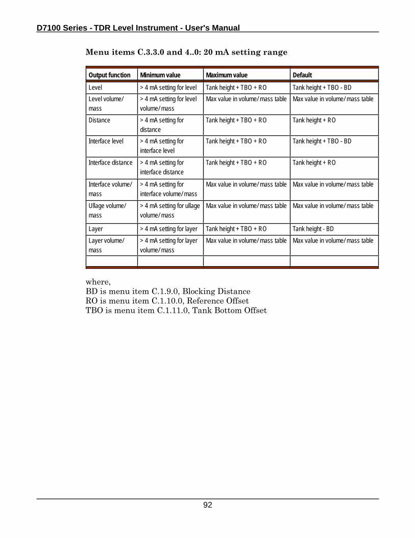
D7100 Series - TDR Level Instrument - User's Manual
92
Menu items C.3.3.0 and 4..0: 20 mA setting range
where,BD is menu item C.1.9.0, Blocking DistanceRO is menu item C.1.10.0, Reference OffsetTBO is menu item C.1.11.0, Tank Bottom Offset
Output function Minimum value Maximum value Default
Level > 4 mA setting for level Tank height + TBO + RO Tank height + TBO - BDLevel volume/ mass
> 4 mA setting for level volume/ mass
Max value in volume/ mass table Max value in volume/ mass table
Distance > 4 mA setting for distance
Tank height + TBO + RO Tank height + RO
Interface level > 4 mA setting for interface level
Tank height + TBO + RO Tank height + TBO - BD
Interface distance > 4 mA setting for interface distance
Tank height + TBO + RO Tank height + RO
Interface volume/ mass
> 4 mA setting for interface volume/ mass
Max value in volume/ mass table Max value in volume/ mass table
Ullage volume/ mass
> 4 mA setting for ullage volume/ mass
Max value in volume/ mass table Max value in volume/ mass table
Layer > 4 mA setting for layer Tank height + TBO + RO Tank height - BDLayer volume/ mass
> 4 mA setting for layer volume/ mass
Max value in volume/ mass table Max value in volume/ mass table
Operation
93
4.2.4 Advanced setup: further notes
General notes
The menu items listed below may only be re-configured by a user with supervisor rights.
Using the advanced setup menu, you can
• change the parameters for one or more functions without going through a quick setup procedure
• use individual menu items to manually override automatic settingq assigned during quick setup procedures
Critical parameters
Risk of measurement error
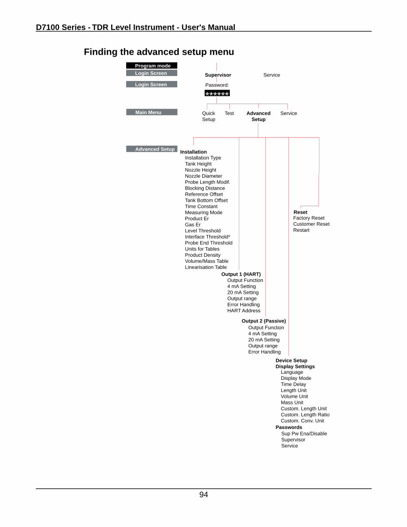
D7100 Series - TDR Level Instrument - User's Manual
94
Finding the advanced setup menu
Advanced Setup
Program mode
Main Menu Quick Test Advanced ServiceSetup Setup
Installation
Login Screen Supervisor Service
Login Screen Password:
******
Installation TypeTank HeightNozzle HeightNozzle DiameterProbe Length Modif.Blocking DistanceReference OffsetTank Bottom OffsetTime ConstantMeasuring ModeProduct ErGas ErLevel ThresholdInterface Threshold*Probe End ThresholdUnits for TablesProduct DensityVolume/Mass TableLinearisation Table
Output Function4 mA Setting20 mA SettingOutput rangeError HandlingHART Address
Output Function4 mA Setting20 mA SettingOutput rangeError Handling
Display Settings
Passwords
Factory ResetCustomer ResetRestart
LanguageDisplay ModeTime DelayLength UnitVolume UnitMass UnitCustom. Length UnitCustom. Length RatioCustom. Conv. Unit
Sup Pw Ena/DisableSupervisorService
Output 2 (Passive)
Output 1 (HART)
Reset
Device Setup
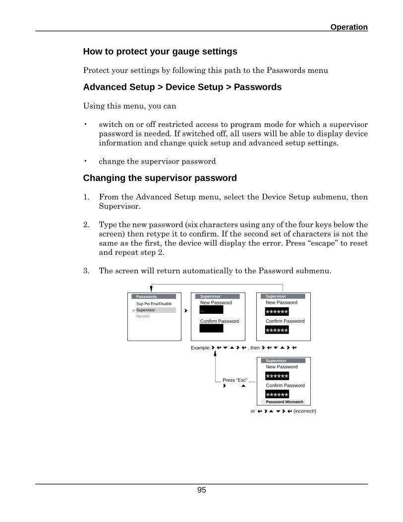
Operation
95
How to protect your gauge settings
Protect your settings by following this path to the Passwords menu
Advanced Setup > Device Setup > Passwords
Using this menu, you can
• switch on or off restricted access to program mode for which a supervisor password is needed. If switched off, all users will be able to display device information and change quick setup and advanced setup settings.
• change the supervisor password
Changing the supervisor password
1. From the Advanced Setup menu, select the Device Setup submenu, then Supervisor.
2. Type the new password (six characters using any of the four keys below the screen) then retype it to confirm. If the second set of characters is not the same as the first, the device will display the error. Press “escape” to reset and repeat step 2.
3. The screen will return automatically to the Password submenu.
Passwords
Sup Pw Ena/Disable
Supervisor
Service
>
Supervisor
New Password_
Confirm Password
Supervisor
New Password
******Confirm Password
******Password Mismatch
Supervisor
New Password
******Confirm Password
******
Example: , then
or (incorrect!)
Press "Esc"
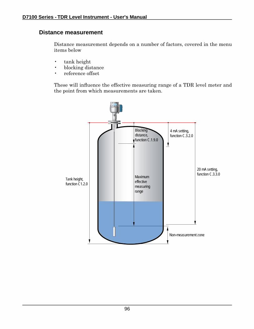
D7100 Series - TDR Level Instrument - User's Manual
96
Distance measurement
Distance measurement depends on a number of factors, covered in the menu items below
• tank height• blocking distance• reference offset
These will influence the effective measuring range of a TDR level meter and the point from which measurements are taken.
Maximumeffectivemeasuringrange
Blockingdistance,function C.1.9.0
4 mA setting,function C.3.2.0
20 mA setting,function C.3.3.0
Non-measurement zone
Tank height,function C1.2.0
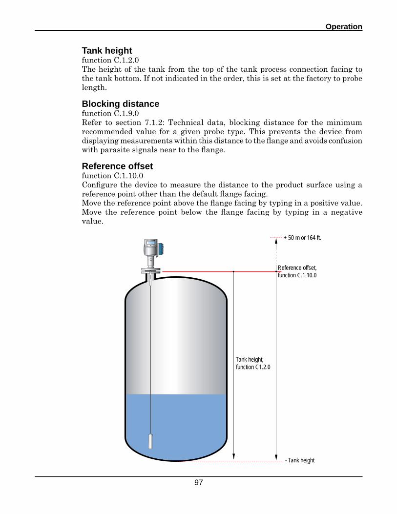
Operation
97
Tank heightfunction C.1.2.0The height of the tank from the top of the tank process connection facing to the tank bottom. If not indicated in the order, this is set at the factory to probe length.
Blocking distancefunction C.1.9.0Refer to section 7.1.2: Technical data, blocking distance for the minimum recommended value for a given probe type. This prevents the device from displaying measurements within this distance to the flange and avoids confusion with parasite signals near to the flange.
Reference offsetfunction C.1.10.0Configure the device to measure the distance to the product surface using a reference point other than the default flange facing.Move the reference point above the flange facing by typing in a positive value. Move the reference point below the flange facing by typing in a negative value.
Reference offset,function C.1.10.0
- Tank height
+ 50 m or 164 ft.
Tank height,function C1.2.0
D7100 Series - TDR Level Instrument - User's Manual
98
Scaling the current output
The current output setup mode is used to create current output scales for the first and second (if ordered) outputs that meet your requirements. You must define:
1. Output function function C.3.1.0 (output 1-level) function C.4.1.0 (output 2-Interface level?)
2. 4 mA setting function C.3.2.0 (output 1) function C.4.2.0 (output 2)
3. 20 mA setting function C.3.3.0 (output 1) function C.4.3.0 (output 2)
4 and 20 mA settings are defined in terms of distance from the flange facing or reference offset. These are the minimum and maximum points of your measuring scale.
Using the optional second output, you can set up a separate scale for measuring interface
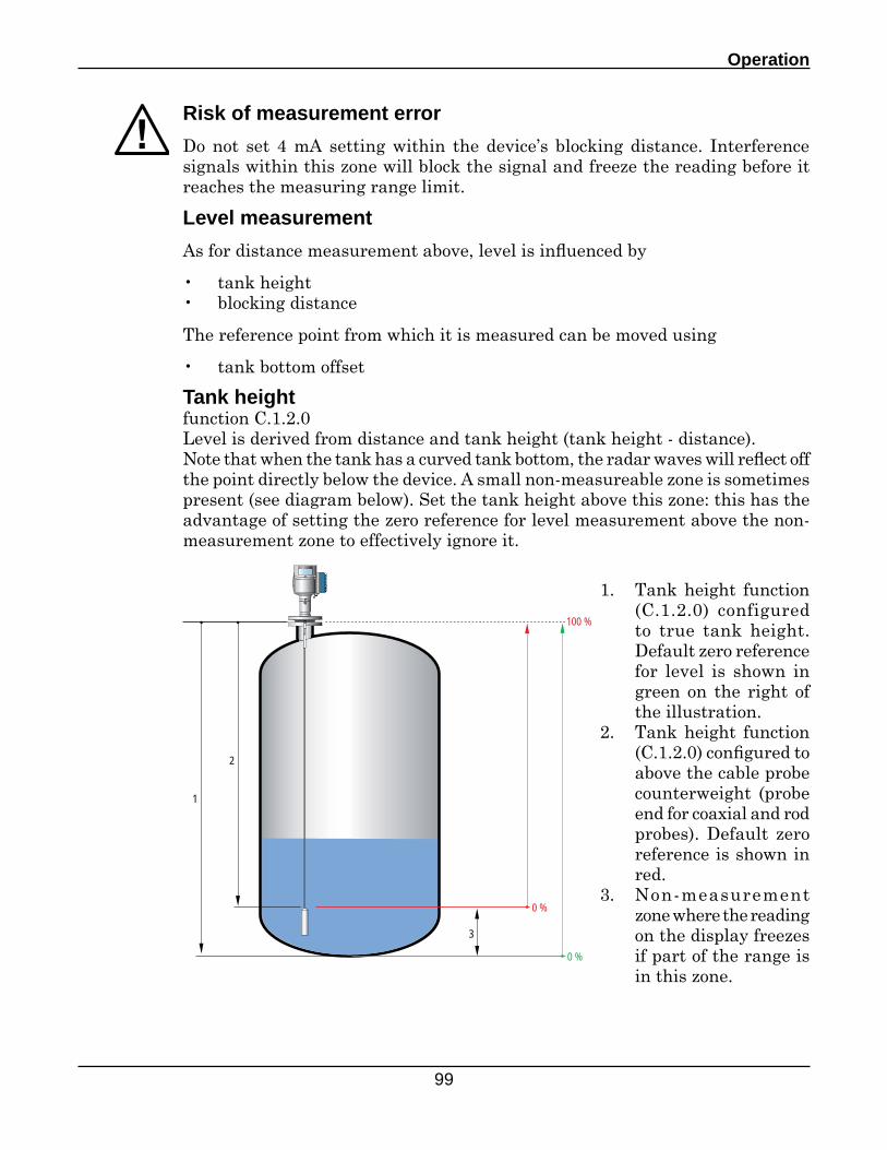
Operation
99
Risk of measurement error
Do not set 4 mA setting within the device’s blocking distance. Interference signals within this zone will block the signal and freeze the reading before it reaches the measuring range limit.
Level measurement
As for distance measurement above, level is influenced by
• tank height• blocking distance
The reference point from which it is measured can be moved using
• tank bottom offset Tank height
function C.1.2.0Level is derived from distance and tank height (tank height - distance). Note that when the tank has a curved tank bottom, the radar waves will reflect off the point directly below the device. A small non-measureable zone is sometimes present (see diagram below). Set the tank height above this zone: this has the advantage of setting the zero reference for level measurement above the non-measurement zone to effectively ignore it.
1
2
3
0 %
100 %
0 %
1. Tank height function (C.1.2.0) configured to true tank height. Default zero reference for level is shown in green on the right of the illustration.
2. Tank height function (C.1.2.0) configured to above the cable probe counterweight (probe end for coaxial and rod probes). Default zero reference is shown in red.
3. Non-measurement zone where the reading on the display freezes if part of the range is in this zone.
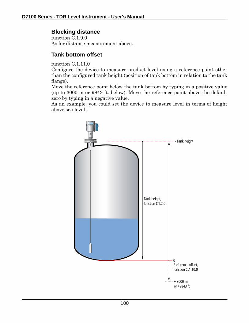
D7100 Series - TDR Level Instrument - User's Manual
100
Blocking distancefunction C.1.9.0As for distance measurement above.
Tank bottom offset
function C.1.11.0Configure the device to measure product level using a reference point other than the configured tank height (position of tank bottom in relation to the tank flange).Move the reference point below the tank bottom by typing in a positive value (up to 3000 m or 9843 ft. below). Move the reference point above the default zero by typing in a negative value.As an example, you could set the device to measure level in terms of height above sea level.
Reference offset,function C.1.10.0
- Tank height
+ 3000 mor +9843 ft.
0
Tank height,function C1.2.0
Operation
101
Scaling the current output
The current output setup mode is used to create current output scales for the first and second (if ordered) outputs that meet your requirements. You must define:
1. Output function function C.3.1.0 (output 1-distance) function C.4.1.0 (output 2-other: interface distance?)
2. 4 mA setting function C.3.2.0 (output 1) function C.4.2.0 (output 2)
3. 20 mA setting function C.3.3.0 (output 1) function C.4.3.0 (output 2)
4 and 20 mA settings are defined in terms of distance from the tank bottom or tank bottom offset. These are the minimum and maximum points of your measuring scale.
Using the optional second output, you can set up a separate scale for measuring interface.
Volume or mass measurement
Volume/Mass tablefunction C.1.21.0
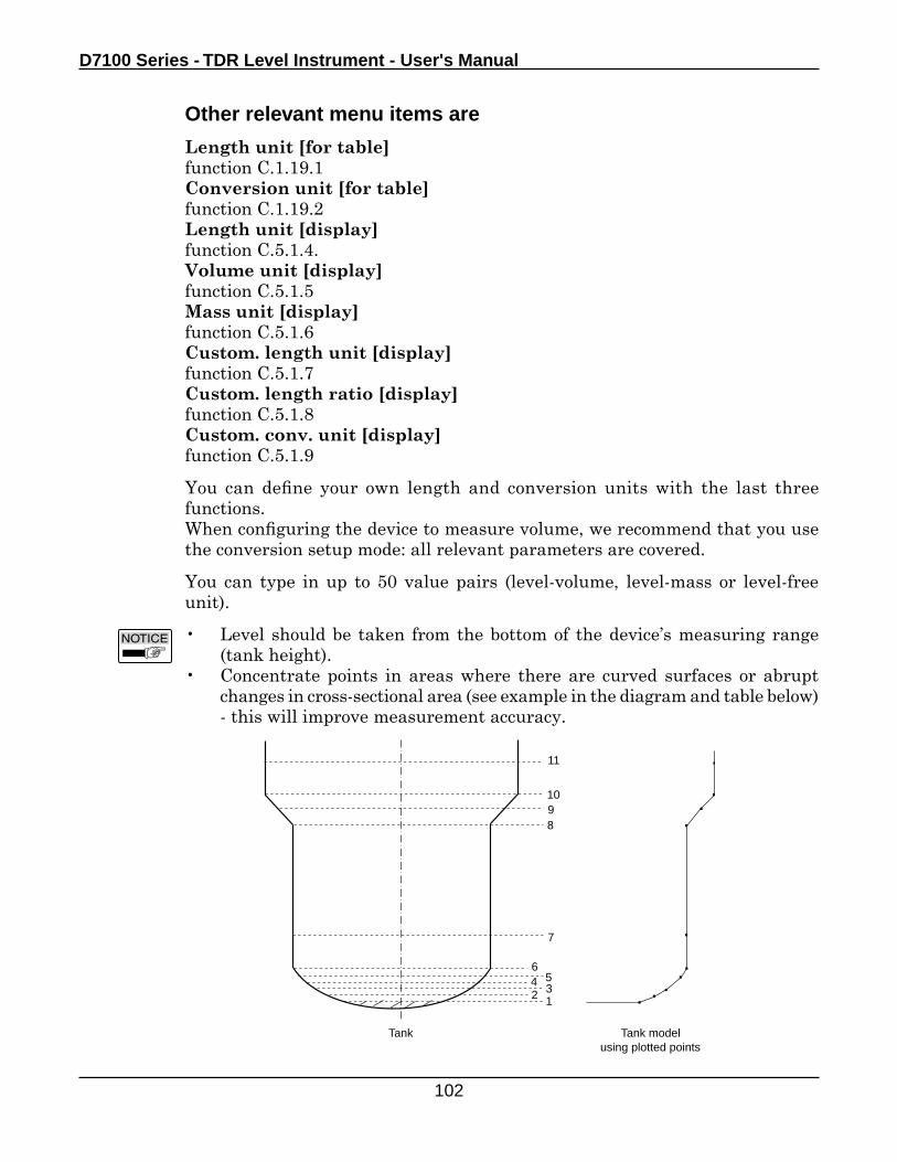
D7100 Series - TDR Level Instrument - User's Manual
102
Other relevant menu items are
Length unit [for table]function C.1.19.1Conversion unit [for table]function C.1.19.2Length unit [display]function C.5.1.4.Volume unit [display]function C.5.1.5Mass unit [display]function C.5.1.6Custom. length unit [display]function C.5.1.7Custom. length ratio [display]function C.5.1.8Custom. conv. unit [display]function C.5.1.9
You can define your own length and conversion units with the last three functions.When configuring the device to measure volume, we recommend that you use the conversion setup mode: all relevant parameters are covered.
You can type in up to 50 value pairs (level-volume, level-mass or level-free unit).
• Level should be taken from the bottom of the device’s measuring range (tank height).
• Concentrate points in areas where there are curved surfaces or abrupt changes in cross-sectional area (see example in the diagram and table below) - this will improve measurement accuracy.
12
564
3
7
8910
11
Tank Tank model using plotted points
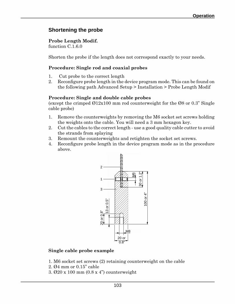
Operation
103
Shortening the probe
Probe Length Modif.function C.1.6.0
Shorten the probe if the length does not correspond exactly to your needs.
Procedure: Single rod and coaxial probes
1. Cut probe to the correct length2. Reconfigure probe length in the device program mode. This can be found on
the following path Advanced Setup > Installation > Probe Length Modif
Procedure: Single and double cable probes(except the crimped Ø12x100 mm rod counterweight for the Ø8 or 0.3” Single cable probe)
1. Remove the counterweights by removing the M6 socket set screws holding the weights onto the cable. You will need a 3 mm hexagon key.
2. Cut the cables to the correct length - use a good quality cable cutter to avoid the strands from splaying
3. Remount the counterweights and retighten the socket set screws.4. Reconfigure probe length in the device program mode as in the procedure
above.
Single cable probe example
1. M6 socket set screws (2) retaining counterweight on the cable2. Ø4 mm or 0.15” cable3. Ø20 x 100 mm (0.8 x 4”) counterweight
M6
30 o
r 1.
2"
100
or 4
"
M8
20 or0.8"
20 o
r 0.
8" 13 o
r 0.
5"
1
2
3
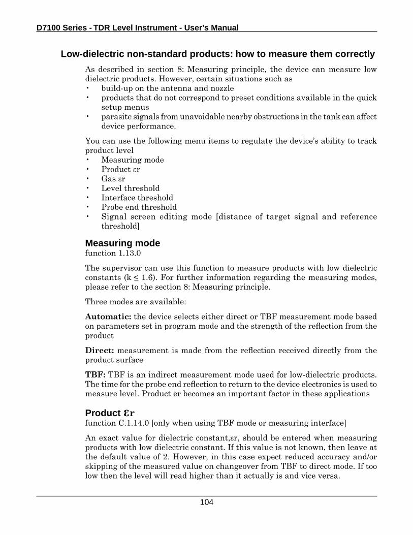
D7100 Series - TDR Level Instrument - User's Manual
104
Low-dielectric non-standard products: how to measure them correctly
As described in section 8: Measuring principle, the device can measure low dielectric products. However, certain situations such as• build-up on the antenna and nozzle• products that do not correspond to preset conditions available in the quick
setup menus• parasite signals from unavoidable nearby obstructions in the tank can affect
device performance.
You can use the following menu items to regulate the device’s ability to track product level• Measuring mode• Product r• Gas r• Level threshold• Interface threshold• Probe end threshold• Signal screen editing mode [distance of target signal and reference
threshold]
Measuring modefunction 1.13.0
The supervisor can use this function to measure products with low dielectric constants (k _< 1.6). For further information regarding the measuring modes, please refer to the section 8: Measuring principle.
Three modes are available:
Automatic: the device selects either direct or TBF measurement mode based on parameters set in program mode and the strength of the reflection from the product
Direct: measurement is made from the reflection received directly from the product surface
TBF: TBF is an indirect measurement mode used for low-dielectric products. The time for the probe end reflection to return to the device electronics is used to measure level. Product er becomes an important factor in these applications
Product rfunction C.1.14.0 [only when using TBF mode or measuring interface]
An exact value for dielectric constant,r, should be entered when measuring products with low dielectric constant. If this value is not known, then leave at the default value of 2. However, in this case expect reduced accuracy and/or skipping of the measured value on changeover from TBF to direct mode. If too low then the level will read higher than it actually is and vice versa.
Operation
105
Gas rfunction C.1.15.0
In solid applications where there is a lot of dust in the air above the product it may be necessary incease the value of Gas r slightly to improve accuracy. Please contact our local service centers for further assistance. For all other applications use the the default value of 1. Use this function if the probe is entirely coated with a regular layer of residue or dust from the product.
ThresholdsAs explained in the measuring principle, DR7100 emits a low-power electromagnetic signal that reflects back from the the product surface and any other protuding objects in the tank. These signals are converted to voltage amplitudes by the signal converter.Reflections from the internal tank components are known as parasite or interference signals. A method of filtering out these signals, called thresholds, permits reflections under a given voltage amplitude to be ignored and measurements to be made correctly. As voltage amplitude also decreases over distance, this threshold decreases according to a mathematical formula.The first return signal over the threshold is identified as the product surface. Once identified, the signal converter has to process the signal: it amplifies the signal (defined by levels of Gain: 0 to 3) to use it for measurement purposes. A strong return signal will be given a Gain 0 or low amplification, while a weak signal will be given Gain 3 or high amplification.Normally the signal converter will automatically identify the signals to be measured and adjust the Gain to follow the same signal along the length of the probe as the tank is filled or emptied. However, if there are large and/or too many other objects in the tank and the signal converter has problems following the signal then the threshold may need adjusting manually to suit the installation.The DR7100 allows three thresholds to be modified manually:
Menu item C.1.16.0 level: for identifying the top product surface,Menu item C.1.17.0 interface: for identifying the interface when there is more than one product in the tank andMenu item C.1.18.0 probe end: for identifying the end of the probe (important for TBF mode)
In order for the user to identify the correct signal, the signal screen in normal mode must be used. As described in Operator control, this displays the 5 to 10 biggest reflections in terms of voltage amplitude/mV against distance/m. The user can move the cursor from point to point to obtain values for each point.Knowing the real distance of the level, interface or probe end from the flange face, the correct value can be identified. A voltage amplitude value slightly less than the correct value but higher than the interference signals can then be typed into the relevant threshold function to allow the signal converter to correctly identify what it should be monitoring.
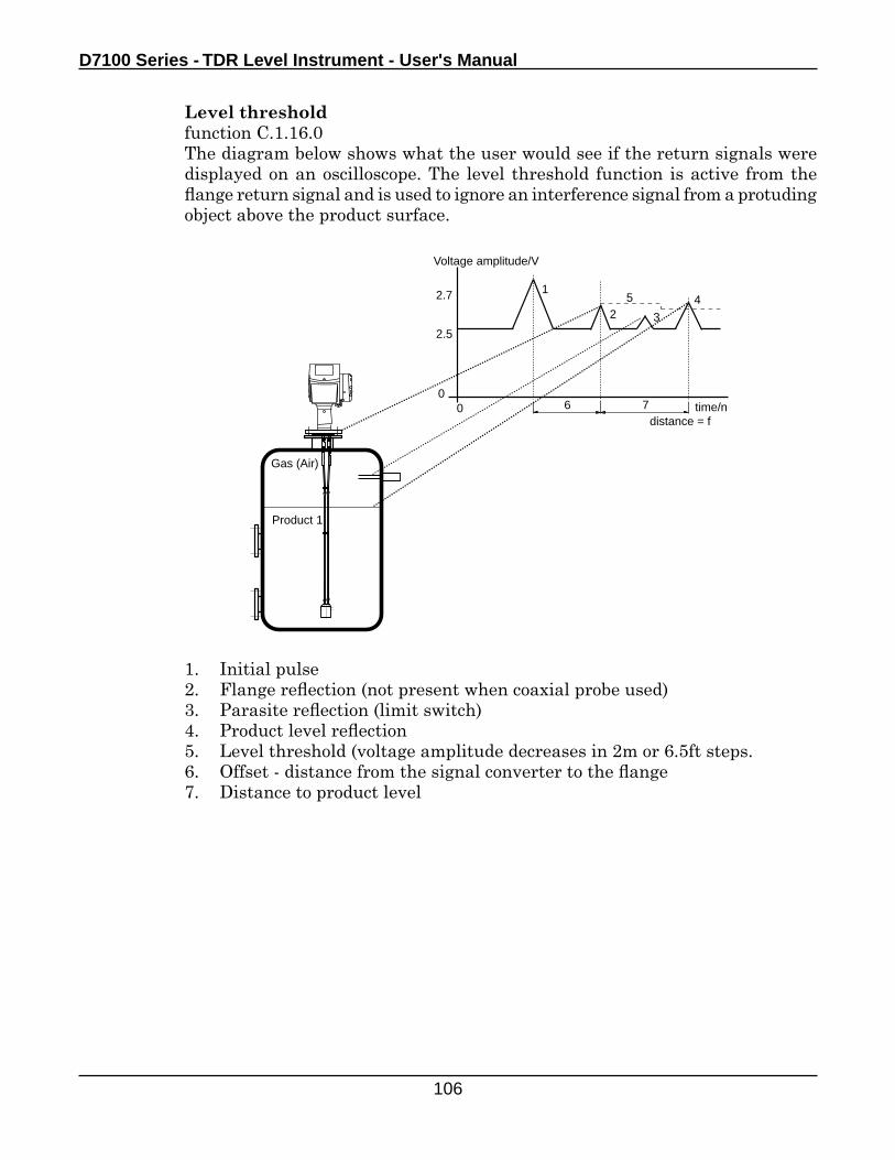
D7100 Series - TDR Level Instrument - User's Manual
106
Level thresholdfunction C.1.16.0The diagram below shows what the user would see if the return signals were displayed on an oscilloscope. The level threshold function is active from the flange return signal and is used to ignore an interference signal from a protuding object above the product surface.
1. Initial pulse2. Flange reflection (not present when coaxial probe used)3. Parasite reflection (limit switch)4. Product level reflection5. Level threshold (voltage amplitude decreases in 2m or 6.5ft steps.6. Offset - distance from the signal converter to the flange7. Distance to product level
00
Voltage amplitude/V
time/ndistance = f
1
2 3
45
6 7
2.7
2.5
Product 1
Gas (Air)
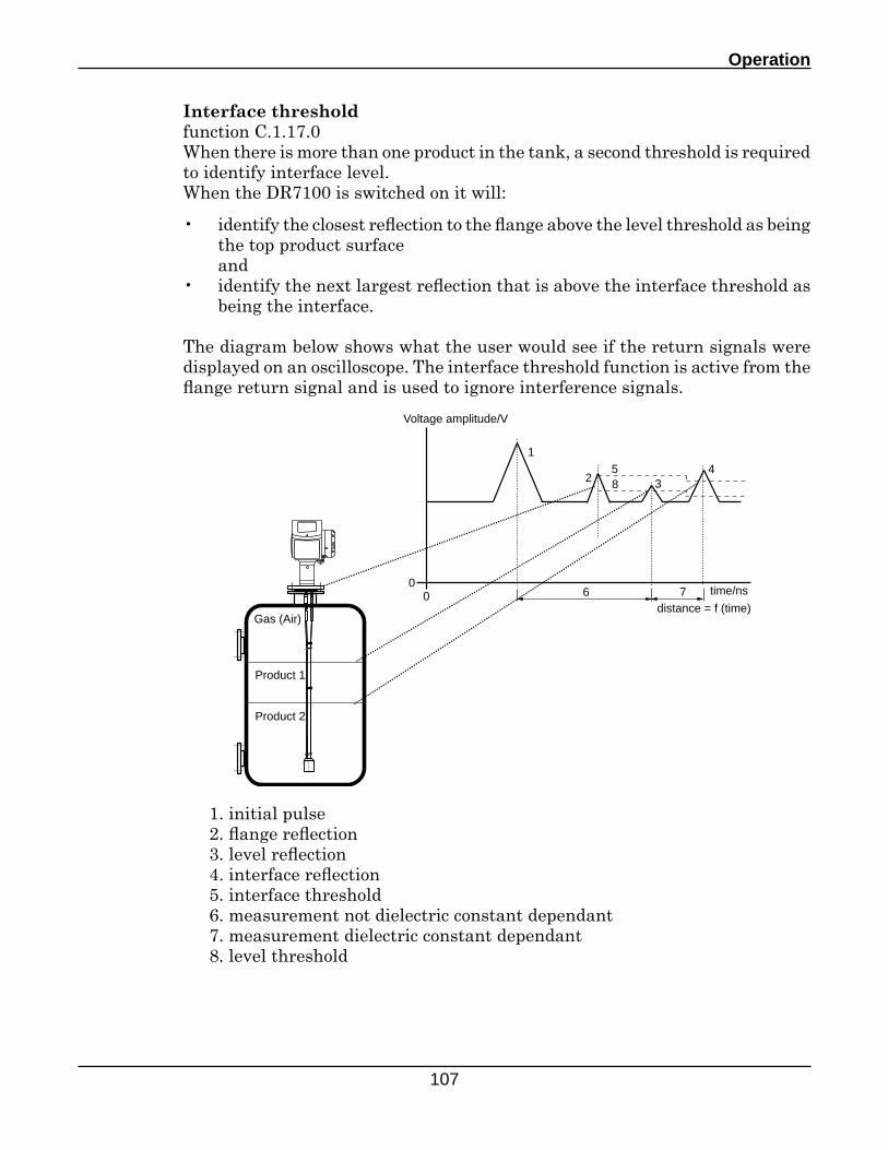
Operation
107
Interface thresholdfunction C.1.17.0When there is more than one product in the tank, a second threshold is required to identify interface level.When the DR7100 is switched on it will:
• identify the closest reflection to the flange above the level threshold as being the top product surface
and • identify the next largest reflection that is above the interface threshold as
being the interface.
The diagram below shows what the user would see if the return signals were displayed on an oscilloscope. The interface threshold function is active from the flange return signal and is used to ignore interference signals.
00
Voltage amplitude/V
time/ns
distance = f (time)
1
2 345
6 7
8
Product 1
Gas (Air)
Product 2
1. initial pulse2. flange reflection3. level reflection4. interface reflection5. interface threshold6. measurement not dielectric constant dependant7. measurement dielectric constant dependant8. level threshold
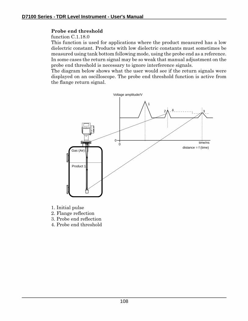
D7100 Series - TDR Level Instrument - User's Manual
108
Probe end thresholdfunction C.1.18.0This function is used for applications where the product measured has a low dielectric constant. Products with low dielectric constants must sometimes be measured using tank bottom following mode, using the probe end as a reference. In some cases the return signal may be so weak that manual adjustment on the probe end threshold is necessary to ignore interference signals.The diagram below shows what the user would see if the return signals were displayed on an oscilloscope. The probe end threshold function is active from the flange return signal.
1. Initial pulse2. Flange reflection3. Probe end reflection4. Probe end threshold
00
Voltage amplitude/V
time/ns
distance = f (time)
1
2 34
Product 1
Gas (Air)
Operation
109
On-site device calibration
Linearisation tablefunction C.1.22.0
For on-site calibration.
Linearisation procedure1. Fill the tank to any given level.2. Go to the linearisation table menu item via advanced setup > installation.
The level reading will be displayed with the possibility to enter a different value
3. Make an appropriate reference measurement.4. Type in the corrected value and confirm5. Repeat procedure (50 points maximum).
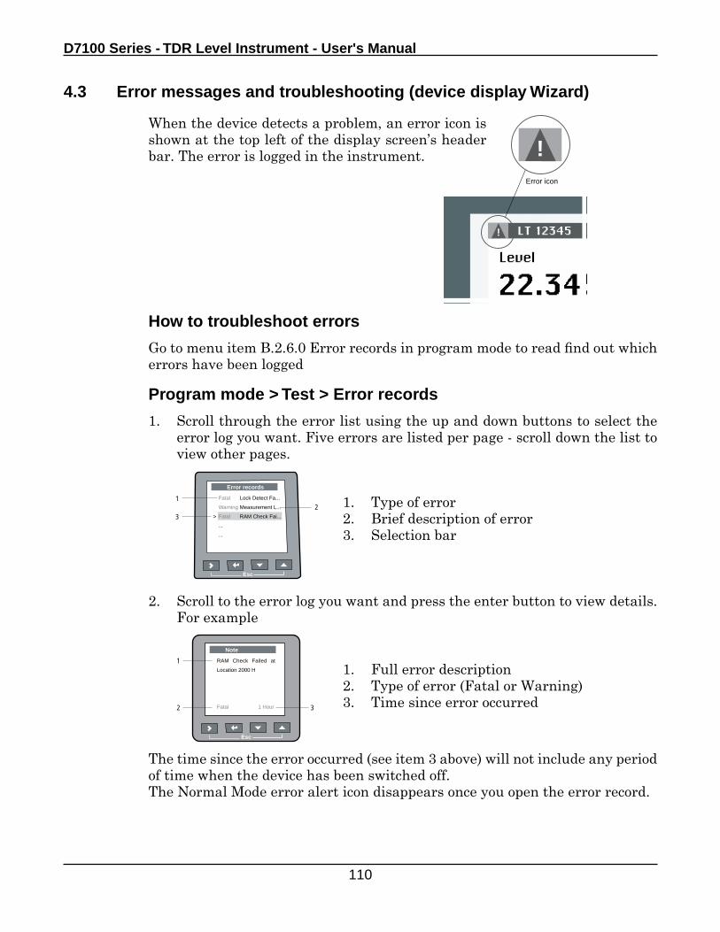
D7100 Series - TDR Level Instrument - User's Manual
110
4.3 Error messages and troubleshooting (device display Wizard)
!
!Error icon
How to troubleshoot errors
Go to menu item B.2.6.0 Error records in program mode to read find out which errors have been logged
Program mode > Test > Error records
1. Scroll through the error list using the up and down buttons to select the error log you want. Five errors are listed per page - scroll down the list to view other pages.
1. Type of error2. Brief description of error3. Selection bar
1. Full error description2. Type of error (Fatal or Warning)3. Time since error occurred
The time since the error occurred (see item 3 above) will not include any period of time when the device has been switched off.The Normal Mode error alert icon disappears once you open the error record.
2. Scroll to the error log you want and press the enter button to view details. For example
2
Esc
Error records
Fatal Lock Detect Fa...
Warning Measurement L...
Fatal RAM Check Fai...
...
...
>
1
3
Esc
Note
RAM Check Failed at
Location 2000 H
Fatal 1 Hour
1
2 3
When the device detects a problem, an error icon is shown at the top left of the display screen’s header bar. The error is logged in the instrument.
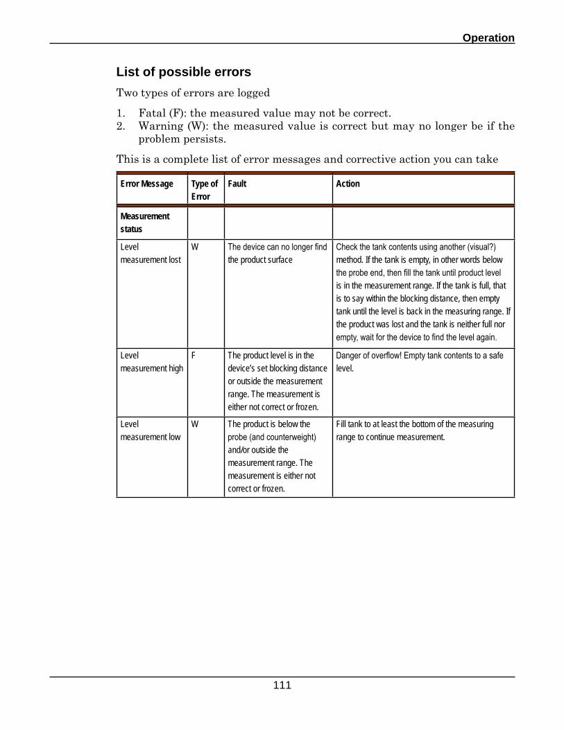
Operation
111
List of possible errors
Two types of errors are logged
1. Fatal (F): the measured value may not be correct.2. Warning (W): the measured value is correct but may no longer be if the
problem persists.
This is a complete list of error messages and corrective action you can take
Error Message Type of Error
Fault Action
Measurement status
Level measurement lost
W The device can no longer find the product surface
Check the tank contents using another (visual?) method. If the tank is empty, in other words below the probe end, then fill the tank until product level is in the measurement range. If the tank is full, that is to say within the blocking distance, then empty tank until the level is back in the measuring range. If the product was lost and the tank is neither full nor empty, wait for the device to find the level again.
Level measurement high
F The product level is in the device’s set blocking distance or outside the measurement range. The measurement is either not correct or frozen.
Danger of overflow! Empty tank contents to a safe level.
Level measurement low
W The product is below the probe (and counterweight) and/or outside the measurement range. The measurement is either not correct or frozen.
Fill tank to at least the bottom of the measuring range to continue measurement.
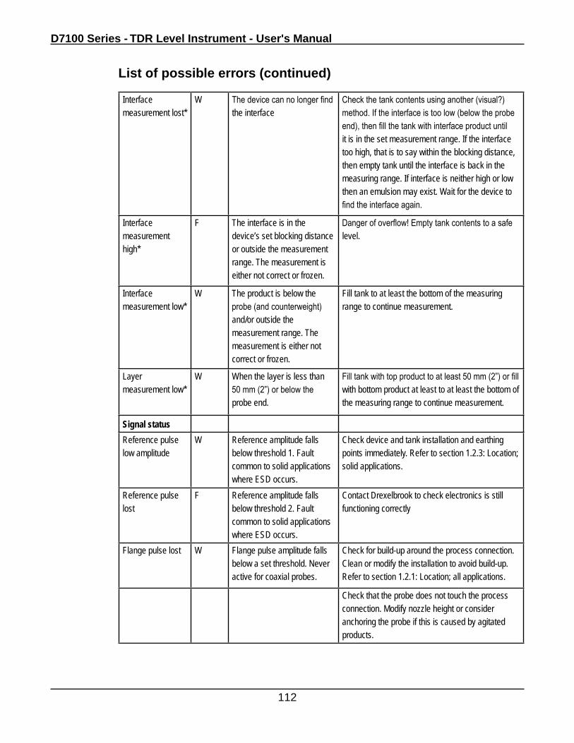
D7100 Series - TDR Level Instrument - User's Manual
112
Interface measurement lost*
W The device can no longer find the interface
Check the tank contents using another (visual?) method. If the interface is too low (below the probe end), then fill the tank with interface product until it is in the set measurement range. If the interface too high, that is to say within the blocking distance, then empty tank until the interface is back in the measuring range. If interface is neither high or low then an emulsion may exist. Wait for the device to find the interface again.
Interface measurement high*
F The interface is in the device’s set blocking distance or outside the measurement range. The measurement is either not correct or frozen.
Danger of overflow! Empty tank contents to a safe level.
Interface measurement low*
W The product is below the probe (and counterweight) and/or outside the measurement range. The measurement is either not correct or frozen.
Fill tank to at least the bottom of the measuring range to continue measurement.
Layer measurement low*
W When the layer is less than 50 mm (2”) or below the probe end.
Fill tank with top product to at least 50 mm (2”) or fill with bottom product at least to at least the bottom of the measuring range to continue measurement.
Signal statusReference pulse low amplitude
W Reference amplitude falls below threshold 1. Fault common to solid applications where ESD occurs.
Check device and tank installation and earthing points immediately. Refer to section 1.2.3: Location; solid applications.
Reference pulse lost
F Reference amplitude falls below threshold 2. Fault common to solid applications where ESD occurs.
Contact Drexelbrook to check electronics is still functioning correctly
Flange pulse lost W Flange pulse amplitude falls below a set threshold. Never active for coaxial probes.
Check for build-up around the process connection. Clean or modify the installation to avoid build-up. Refer to section 1.2.1: Location; all applications.
Check that the probe does not touch the process connection. Modify nozzle height or consider anchoring the probe if this is caused by agitated products.
List of possible errors (continued)
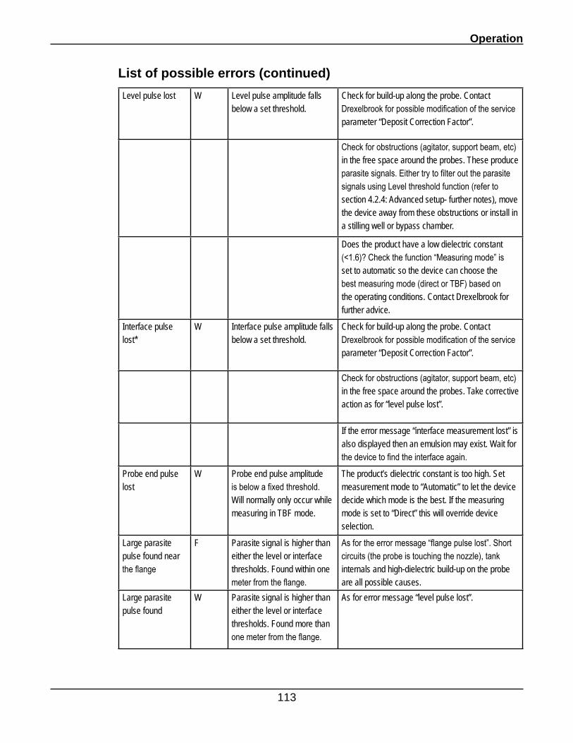
Operation
113
Level pulse lost W Level pulse amplitude falls below a set threshold.
Check for build-up along the probe. Contact Drexelbrook for possible modification of the service parameter “Deposit Correction Factor”.
Check for obstructions (agitator, support beam, etc) in the free space around the probes. These produce parasite signals. Either try to filter out the parasite signals using Level threshold function (refer to section 4.2.4: Advanced setup- further notes), move the device away from these obstructions or install in a stilling well or bypass chamber.
Does the product have a low dielectric constant (<1.6)? Check the function “Measuring mode” is set to automatic so the device can choose the best measuring mode (direct or TBF) based on the operating conditions. Contact Drexelbrook for further advice.
Interface pulse lost*
W Interface pulse amplitude falls below a set threshold.
Check for build-up along the probe. Contact Drexelbrook for possible modification of the service parameter “Deposit Correction Factor”.
Check for obstructions (agitator, support beam, etc) in the free space around the probes. Take corrective action as for “level pulse lost”.
If the error message “interface measurement lost” is also displayed then an emulsion may exist. Wait for the device to find the interface again.
Probe end pulse lost
W Probe end pulse amplitude is below a fixed threshold. Will normally only occur while measuring in TBF mode.
The product’s dielectric constant is too high. Set measurement mode to “Automatic” to let the device decide which mode is the best. If the measuring mode is set to “Direct” this will override device selection.
Large parasite pulse found near the flange
F Parasite signal is higher than either the level or interface thresholds. Found within one meter from the flange.
As for the error message “flange pulse lost”. Short circuits (the probe is touching the nozzle), tank internals and high-dielectric build-up on the probe are all possible causes.
Large parasite pulse found
W Parasite signal is higher than either the level or interface thresholds. Found more than one meter from the flange.
As for error message “level pulse lost”.
List of possible errors (continued)
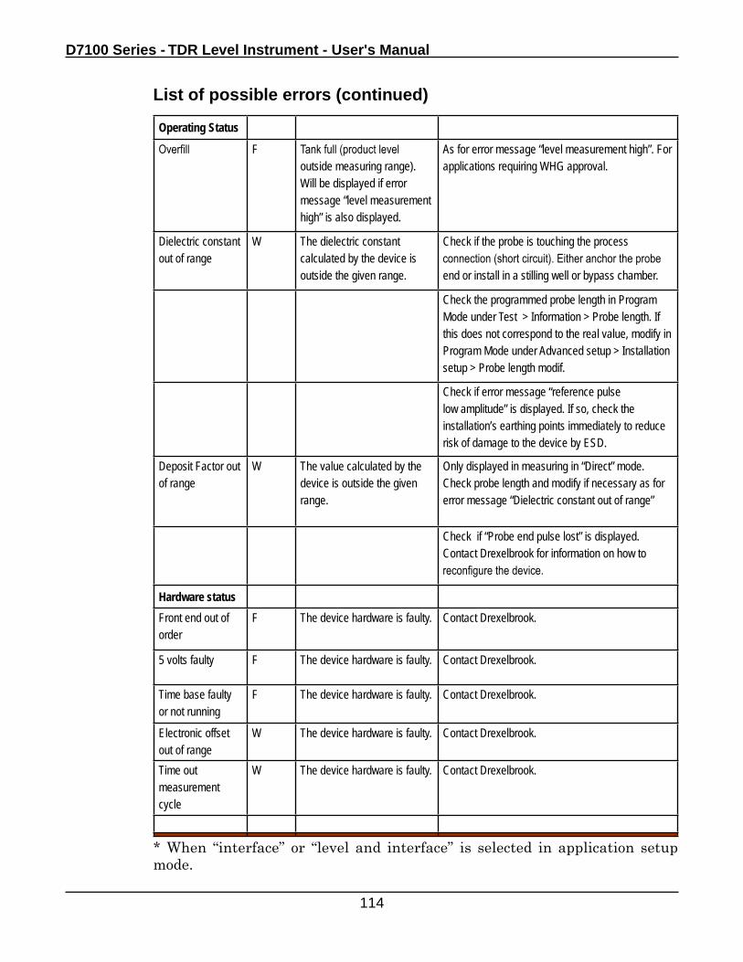
D7100 Series - TDR Level Instrument - User's Manual
114
List of possible errors (continued)
Operating Status
Overfill F Tank full (product level outside measuring range). Will be displayed if error message “level measurement high” is also displayed.
As for error message “level measurement high”. For applications requiring WHG approval.
Dielectric constant out of range
W The dielectric constant calculated by the device is outside the given range.
Check if the probe is touching the process connection (short circuit). Either anchor the probe end or install in a stilling well or bypass chamber.
Check the programmed probe length in Program Mode under Test > Information > Probe length. If this does not correspond to the real value, modify in Program Mode under Advanced setup > Installation setup > Probe length modif.
Check if error message “reference pulse low amplitude” is displayed. If so, check the installation’s earthing points immediately to reduce risk of damage to the device by ESD.
Deposit Factor out of range
W The value calculated by the device is outside the given range.
Only displayed in measuring in “Direct” mode. Check probe length and modify if necessary as for error message “Dielectric constant out of range”
Check if “Probe end pulse lost” is displayed. Contact Drexelbrook for information on how to reconfigure the device.
Hardware statusFront end out of order
F The device hardware is faulty. Contact Drexelbrook.
5 volts faulty F The device hardware is faulty. Contact Drexelbrook.
Time base faulty or not running
F The device hardware is faulty. Contact Drexelbrook.
Electronic offset out of range
W The device hardware is faulty. Contact Drexelbrook.
Time out measurement cycle
W The device hardware is faulty. Contact Drexelbrook.
* When “interface” or “level and interface” is selected in application setup mode.
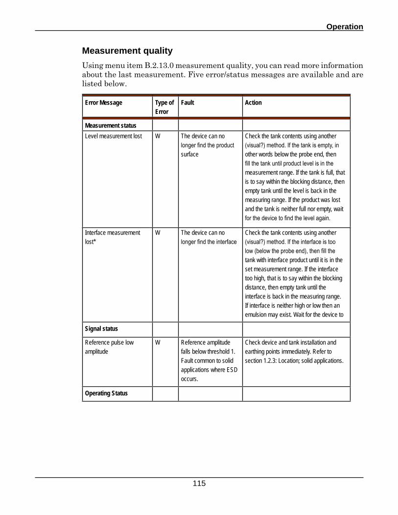
Operation
115
Measurement quality
Using menu item B.2.13.0 measurement quality, you can read more information about the last measurement. Five error/status messages are available and are listed below.
Error Message Type of Error
Fault Action
Measurement statusLevel measurement lost W The device can no
longer find the product surface
Check the tank contents using another (visual?) method. If the tank is empty, in other words below the probe end, then fill the tank until product level is in the measurement range. If the tank is full, that is to say within the blocking distance, then empty tank until the level is back in the measuring range. If the product was lost and the tank is neither full nor empty, wait for the device to find the level again.
Interface measurement lost*
W The device can no longer find the interface
Check the tank contents using another (visual?) method. If the interface is too low (below the probe end), then fill the tank with interface product until it is in the set measurement range. If the interface too high, that is to say within the blocking distance, then empty tank until the interface is back in the measuring range. If interface is neither high or low then an emulsion may exist. Wait for the device to
Signal status
Reference pulse low amplitude
W Reference amplitude falls below threshold 1. Fault common to solid applications where ESD occurs.
Check device and tank installation and earthing points immediately. Refer to section 1.2.3: Location; solid applications.
Operating Status
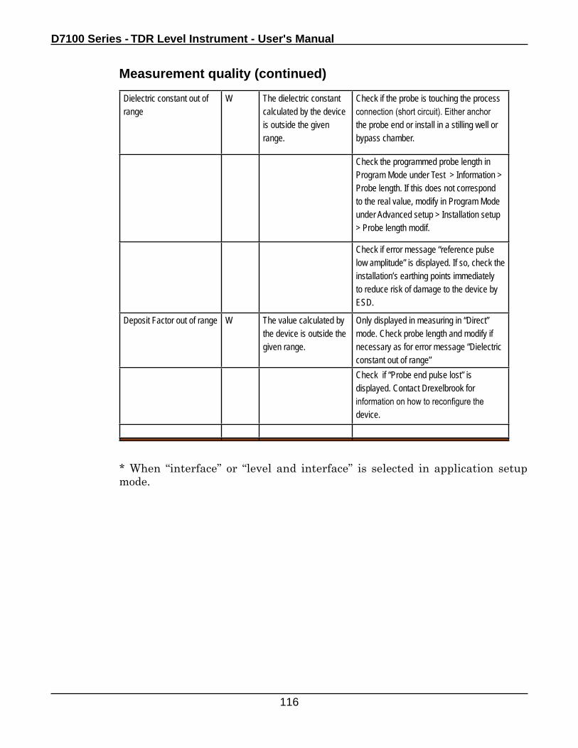
D7100 Series - TDR Level Instrument - User's Manual
116
Dielectric constant out of range
W The dielectric constant calculated by the device is outside the given range.
Check if the probe is touching the process connection (short circuit). Either anchor the probe end or install in a stilling well or bypass chamber.
Check the programmed probe length in Program Mode under Test > Information > Probe length. If this does not correspond to the real value, modify in Program Mode under Advanced setup > Installation setup > Probe length modif.
Check if error message “reference pulse low amplitude” is displayed. If so, check the installation’s earthing points immediately to reduce risk of damage to the device by ESD.
Deposit Factor out of range W The value calculated by the device is outside the given range.
Only displayed in measuring in “Direct” mode. Check probe length and modify if necessary as for error message “Dielectric constant out of range”Check if “Probe end pulse lost” is displayed. Contact Drexelbrook for information on how to reconfigure the device.
* When “interface” or “level and interface” is selected in application setup mode.
Measurement quality (continued)
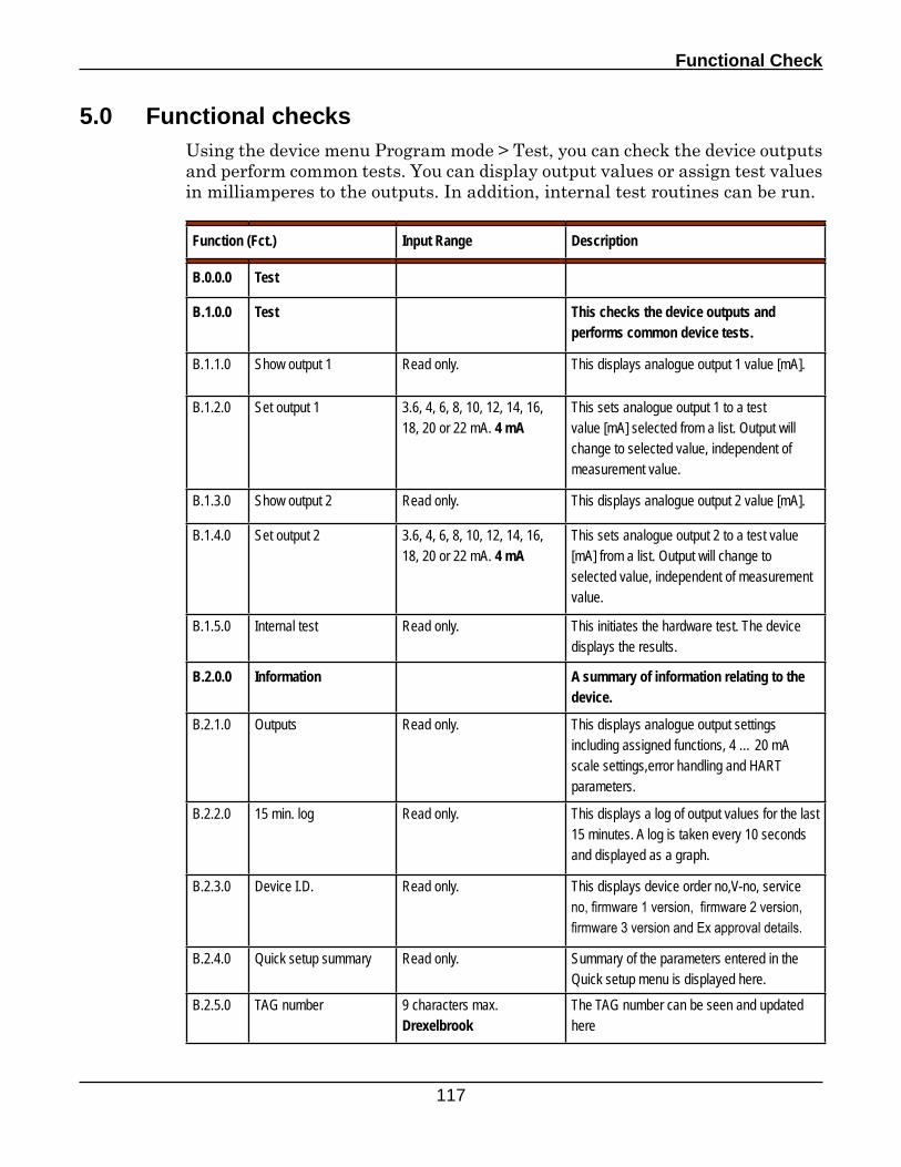
Functional Check
117
5.0 Functional checksUsing the device menu Program mode > Test, you can check the device outputs and perform common tests. You can display output values or assign test values in milliamperes to the outputs. In addition, internal test routines can be run.
Function (Fct.) Input Range Description
B.0.0.0 Test
B.1.0.0 Test This checks the device outputs and performs common device tests.
B.1.1.0 Show output 1 Read only. This displays analogue output 1 value [mA].
B.1.2.0 Set output 1 3.6, 4, 6, 8, 10, 12, 14, 16, 18, 20 or 22 mA. 4 mA
This sets analogue output 1 to a test value [mA] selected from a list. Output will change to selected value, independent of measurement value.
B.1.3.0 Show output 2 Read only. This displays analogue output 2 value [mA].
B.1.4.0 Set output 2 3.6, 4, 6, 8, 10, 12, 14, 16, 18, 20 or 22 mA. 4 mA
This sets analogue output 2 to a test value [mA] from a list. Output will change to selected value, independent of measurement value.
B.1.5.0 Internal test Read only. This initiates the hardware test. The device displays the results.
B.2.0.0 Information A summary of information relating to the device.
B.2.1.0 Outputs Read only. This displays analogue output settings including assigned functions, 4 … 20 mA scale settings,error handling and HART parameters.
B.2.2.0 15 min. log Read only. This displays a log of output values for the last 15 minutes. A log is taken every 10 seconds and displayed as a graph.
B.2.3.0 Device I.D. Read only. This displays device order no,V-no, service no, firmware 1 version, firmware 2 version, firmware 3 version and Ex approval details.
B.2.4.0 Quick setup summary Read only. Summary of the parameters entered in the Quick setup menu is displayed here.
B.2.5.0 TAG number 9 characters max. Drexelbrook
The TAG number can be seen and updated here
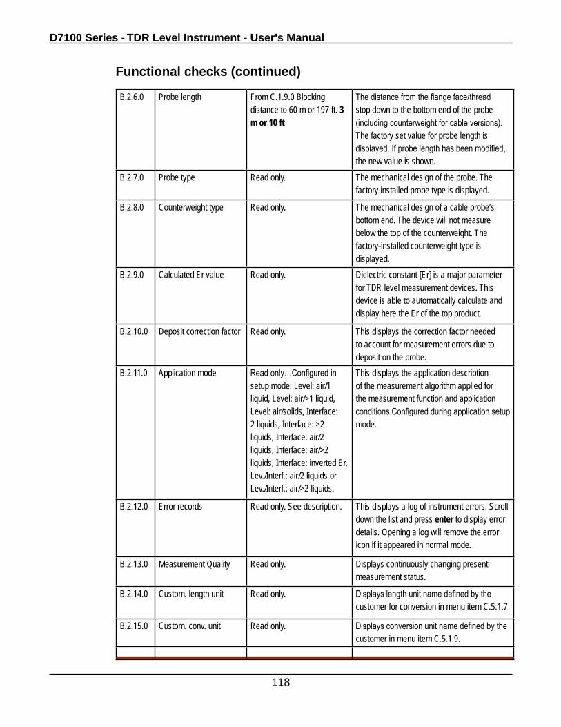
D7100 Series - TDR Level Instrument - User's Manual
118
Functional checks (continued)
B.2.6.0 Probe length From C.1.9.0 Blocking distance to 60 m or 197 ft. 3 m or 10 ft
The distance from the flange face/thread stop down to the bottom end of the probe (including counterweight for cable versions). The factory set value for probe length is displayed. If probe length has been modified, the new value is shown.
B.2.7.0 Probe type Read only. The mechanical design of the probe. The factory installed probe type is displayed.
B.2.8.0 Counterweight type Read only. The mechanical design of a cable probe’s bottom end. The device will not measure below the top of the counterweight. The factory-installed counterweight type is displayed.
B.2.9.0 Calculated Er value Read only. Dielectric constant [Er] is a major parameter for TDR level measurement devices. This device is able to automatically calculate and display here the Er of the top product.
B.2.10.0 Deposit correction factor Read only. This displays the correction factor needed to account for measurement errors due to deposit on the probe.
B.2.11.0 Application mode Read only…Configured in setup mode: Level: air/1 liquid, Level: air/>1 liquid, Level: air/solids, Interface: 2 liquids, Interface: >2 liquids, Interface: air/2 liquids, Interface: air/>2 liquids, Interface: inverted Er, Lev./Interf.: air/2 liquids or Lev./Interf.: air/>2 liquids.
This displays the application description of the measurement algorithm applied for the measurement function and application conditions.Configured during application setup mode.
B.2.12.0 Error records Read only. See description. This displays a log of instrument errors. Scroll down the list and press enter to display error details. Opening a log will remove the error icon if it appeared in normal mode.
B.2.13.0 Measurement Quality Read only. Displays continuously changing present measurement status.
B.2.14.0 Custom. length unit Read only. Displays length unit name defined by the customer for conversion in menu item C.5.1.7
B.2.15.0 Custom. conv. unit Read only. Displays conversion unit name defined by the customer in menu item C.5.1.9.
Service and Maintenance
119
6.0 Service and maintenance
6.1 General notes
Maintenance is normally not required in standard applications. However, heavy deposits on the probe may cause measurement deviations or faulty operation.
Warranty statement
Servicing by the customer is limited by warranty to
• removal and replacement of the housing containing the potted signal converter. Can be detached from the flange system under process conditions. Refer to section 6.2.
Other repairs must be done by Drexelbrook-authorized service staff.
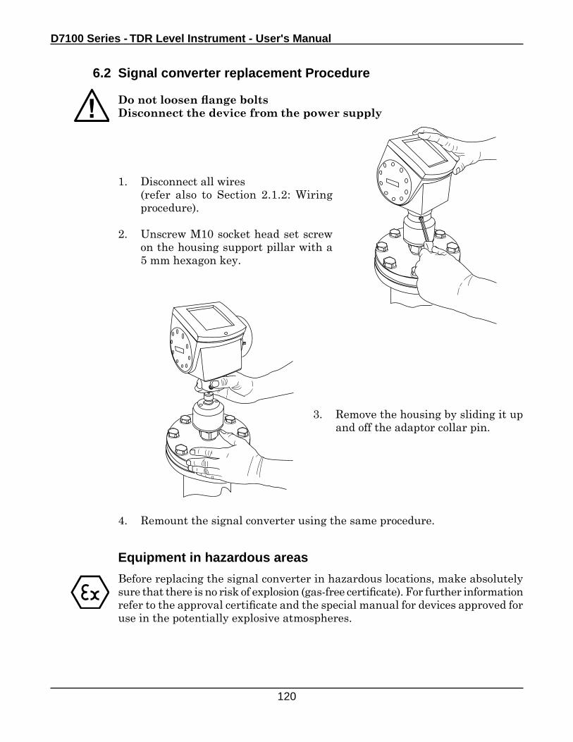
D7100 Series - TDR Level Instrument - User's Manual
120
6.2 Signal converter replacement Procedure
Do not loosen flange boltsDisconnect the device from the power supply
3. Remove the housing by sliding it up and off the adaptor collar pin.
4. Remount the signal converter using the same procedure.
Equipment in hazardous areas
Before replacing the signal converter in hazardous locations, make absolutely sure that there is no risk of explosion (gas-free certificate). For further information refer to the approval certificate and the special manual for devices approved for use in the potentially explosive atmospheres.
1. Disconnect all wires (refer also to Section 2.1.2: Wiring
procedure).
2. Unscrew M10 socket head set screw on the housing support pillar with a 5 mm hexagon key.
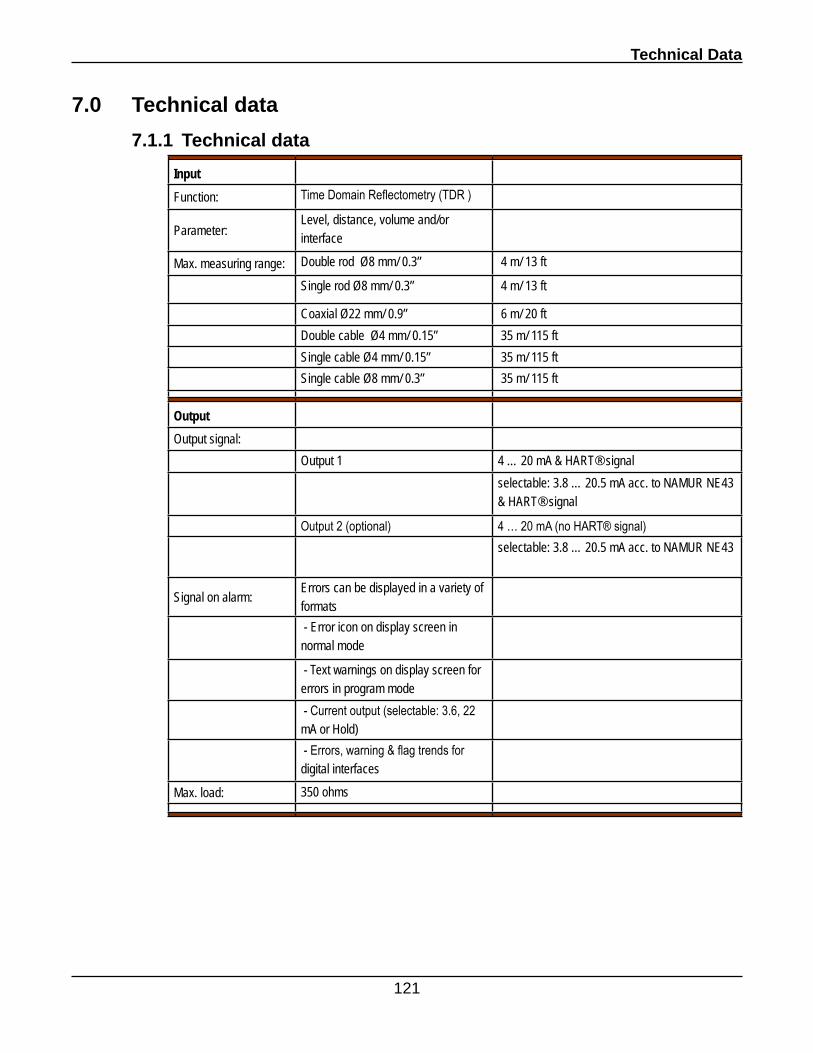
Technical Data
121
7.0 Technical data
7.1.1 Technical data
InputFunction: Time Domain Reflectometry (TDR )
Parameter:Level, distance, volume and/or interface
Max. measuring range: Double rod Ø8 mm/ 0.3” 4 m/ 13 ft
Single rod Ø8 mm/ 0.3” 4 m/ 13 ft
Coaxial Ø22 mm/ 0.9” 6 m/ 20 ftDouble cable Ø4 mm/ 0.15” 35 m/ 115 ftSingle cable Ø4 mm/ 0.15” 35 m/ 115 ftSingle cable Ø8 mm/ 0.3” 35 m/ 115 ft
OutputOutput signal:
Output 1 4 … 20 mA & HART® signalselectable: 3.8 … 20.5 mA acc. to NAMUR NE43 & HART® signal
Output 2 (optional) 4 … 20 mA (no HART® signal)selectable: 3.8 … 20.5 mA acc. to NAMUR NE43
Signal on alarm:Errors can be displayed in a variety of formats - Error icon on display screen in normal mode
- Text warnings on display screen for errors in program mode - Current output (selectable: 3.6, 22 mA or Hold) - Errors, warning & flag trends for digital interfaces
Max. load: 350 ohms
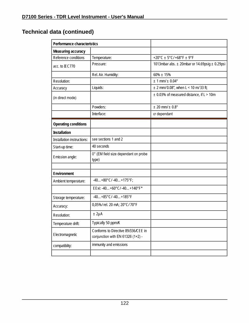
D7100 Series - TDR Level Instrument - User's Manual
122
Performance characteristics
Measuring accuracyReference conditions Temperature: +20°C ± 5°C/ +68°F ± 9°F
acc. to IEC770 Pressure: 1013mbar abs. ± 20mbar or 14.69psig ± 0.29psi
Rel. Air. Humidity: 60% ± 15%Resolution: ± 1 mm/ ± 0.04“Accuracy Liquids: ± 2 mm/ 0.08”, when L < 10 m/ 33 ft;
(in direct mode) ± 0.03% of measured distance, if L > 10m
Powders: ± 20 mm/ ± 0.8“Interface: εr dependant
Operating conditions
InstallationInstallation instructions: see sections 1 and 2
Start-up time: 40 seconds
Emission angle:0° (EM field size dependant on probe type)
Environment
Ambient temperature: -40…+80°C/ -40…+175°F;
EExi: -40…+60°C/ -40…+140°F*
Storage temperature: -40…+85°C/ -40…+185°F
Accuracy: 0,05%/ rel. 20 mA; 20°C/ 70°F
Resolution: ± 2µA
Temperature drift: Typically 50 ppm/K
Electromagnetic Conforms to Directive 89/336/CEE in conjunction with EN 61326 (1+2) -
compatiblity: immunity and emissions
Technical data (continued)
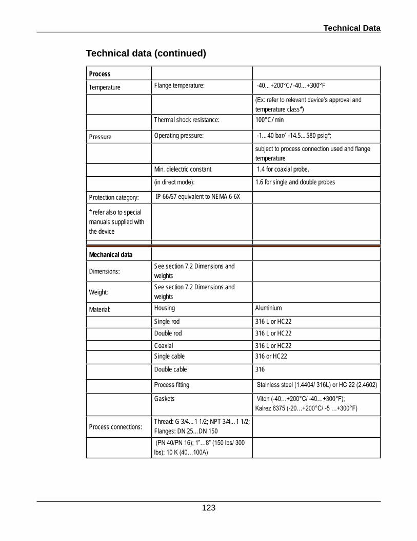
Technical Data
123
Process
Temperature Flange temperature: -40…+200°C/ -40…+300°F
(Ex: refer to relevant device’s approval and temperature class*)
Thermal shock resistance: 100°C/ min
Pressure Operating pressure: -1…40 bar/ -14.5…580 psig*;
subject to process connection used and flange temperature
Min. dielectric constant 1.4 for coaxial probe,
(in direct mode): 1.6 for single and double probes
Protection category: IP 66/67 equivalent to NEMA 6-6X
* refer also to special manuals supplied with the device
Mechanical data
Dimensions:See section 7.2 Dimensions and weights
Weight:See section 7.2 Dimensions and weights
Material: Housing Aluminium
Single rod 316 L or HC22Double rod 316 L or HC22
Coaxial 316 L or HC22Single cable 316 or HC22
Double cable 316
Process fitting Stainless steel (1.4404/ 316L) or HC 22 (2.4602)
Gaskets Viton (-40…+200°C/ -40…+300°F); Kalrez 6375 (-20…+200°C/ -5 …+300°F)
Process connections:Thread: G 3/4…1 1/2; NPT 3/4…1 1/2; Flanges: DN 25…DN 150 (PN 40/PN 16); 1”…8” (150 lbs/ 300 lbs); 10 K (40…100A)
Technical data (continued)
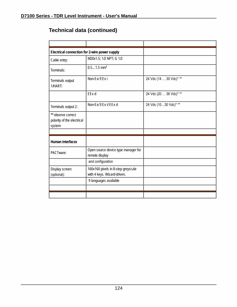
D7100 Series - TDR Level Instrument - User's Manual
124
Electrical connection for 2-wire power supply
Cable entry: M20x1.5; 1/2 NPT; G 1/2
Terminals: 0.5…1.5 mm²
Terminals output 1/HART:
Non-Ex/ EEx i 24 Vdc (14 … 30 Vdc)* **
EEx d 24 Vdc (20 … 36 Vdc)* **
Terminals output 2: Non-Ex/ EEx i/ EEx d 24 Vdc (10…30 Vdc)* **
** observe correct polarity of the electrical system
Human interfaces
PACTware:Open source device type manager for remote display and configuration
Display screen (optional):
160x160 pixels in 8-step greyscale with 4 keys. Wizard-driven. 9 languages available
Technical data (continued)
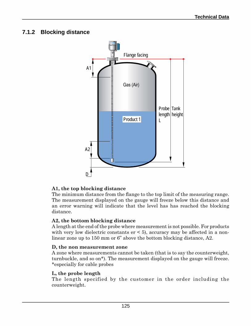
Technical Data
125
7.1.2 Blocking distance
A1, the top blocking distanceThe minimum distance from the flange to the top limit of the measuring range. The measurement displayed on the gauge will freeze below this distance and an error warning will indicate that the level has has reached the blocking distance.
A2, the bottom blocking distanceA length at the end of the probe where measurement is not possible. For products with very low dielectric constants er < 5), accuracy may be affected in a non-linear zone up to 150 mm or 6” above the bottom blocking distance, A2.
D, the non measurement zoneA zone where measurements cannot be taken (that is to say the counterweight, turnbuckle, and so on*). The measurement displayed on the gauge will freeze.*especially for cable probes
L, the probe lengthThe length specified by the customer in the order including the counterweight.
A1
A2
D
Probe lengthL
Tank height
Product 1
Gas (Air)
Flange facing
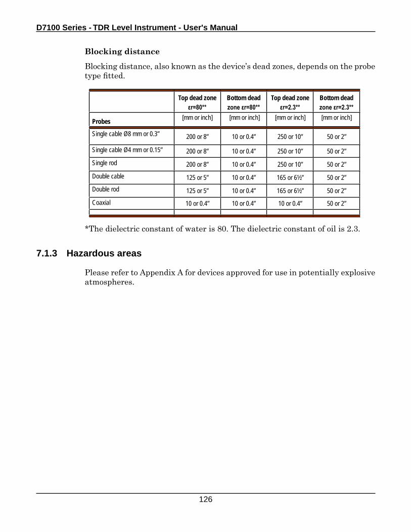
D7100 Series - TDR Level Instrument - User's Manual
126
7.1.3 Hazardous areas
Please refer to Appendix A for devices approved for use in potentially explosive atmospheres.
Blocking distance
Blocking distance, also known as the device’s dead zones, depends on the probe type fitted.
Top dead zone εr=80**
Bottom dead zone εr=80**
Top dead zone εr=2.3**
Bottom dead zone εr=2.3**
Probes [mm or inch] [mm or inch] [mm or inch] [mm or inch]
Single cable Ø8 mm or 0.3” 200 or 8” 10 or 0.4” 250 or 10” 50 or 2”
Single cable Ø4 mm or 0.15” 200 or 8” 10 or 0.4” 250 or 10” 50 or 2”Single rod 200 or 8” 10 or 0.4” 250 or 10” 50 or 2”
Double cable 125 or 5” 10 or 0.4” 165 or 6½” 50 or 2”Double rod 125 or 5” 10 or 0.4” 165 or 6½” 50 or 2”
Coaxial 10 or 0.4” 10 or 0.4” 10 or 0.4” 50 or 2”
*The dielectric constant of water is 80. The dielectric constant of oil is 2.3.
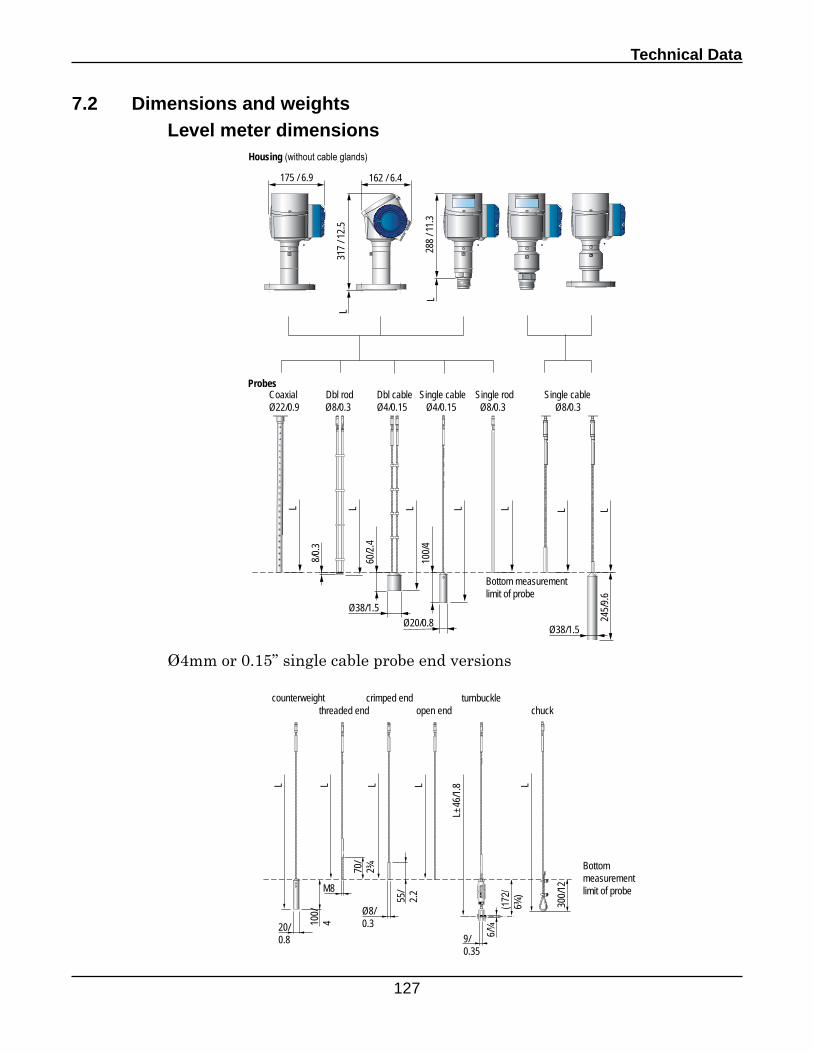
Technical Data
127
7.2 Dimensions and weights Level meter dimensions
175 / 6.9 162 / 6.4
317 /
12.5
288 /
11.3
Probes
Housing (without cable glands)
L
L
Bottom measurement limit of probe
L L L L L L
Coaxial Dbl rod Dbl cable Single cable Single rod Single cableØ22/0.9 Ø8/0.3 Ø4/0.15 Ø4/0.15 Ø8/0.3 Ø8/0.3
L
60/2.
4
Ø38/1.5Ø20/0.8
100/4
8/0.3
Ø38/1.5
245/9
.6
Ø4mm or 0.15” single cable probe end versions
(172
/6¾
)
9/0.35
6/¼20/0.8
100/
4
70/
2¾
M8
55/
2.2
Ø8/ 0.3
300/1
2
Bottom measurement limit of probe
L
L±46
/1.8 LLLL
counterweightthreaded end
crimped endopen end
turnbucklechuck
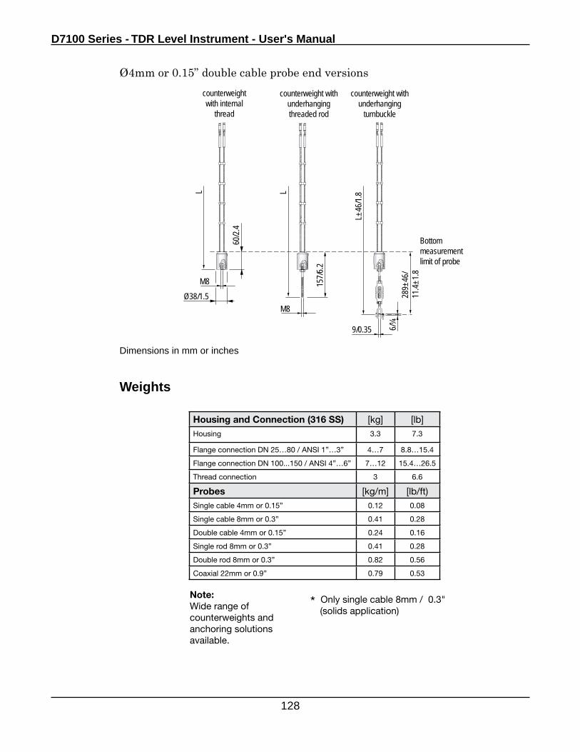
D7100 Series - TDR Level Instrument - User's Manual
128
Weights
Dimensions in mm or inches
M8
9/0.35
Bottom measurement limit of probe
M8
6/¼
60/2.
4
Ø38/1.5LL
counterweight with internal
thread
counterweight with underhanging threaded rod
counterweight with underhanging
turnbuckle
157/6
.2
289±
46/
11.4±
1.8
L±46
/1.8
Housing and Connection (316 SS) [kg] [lb]Housing 3.3 7.3
Flange connection DN 25…80 / ANSI 1”…3” 4…7 8.8…15.4
Flange connection DN 100...150 / ANSI 4”…6” 7…12 15.4…26.5
Thread connection 3 6.6
Probes [kg/m] [lb/ft)Single cable 4mm or 0.15” 0.12 0.08
Single cable 8mm or 0.3” 0.41 0.28
Double cable 4mm or 0.15” 0.24 0.16
Single rod 8mm or 0.3” 0.41 0.28
Double rod 8mm or 0.3” 0.82 0.56
Coaxial 22mm or 0.9” 0.79 0.53
Note:Wide range of counterweights and anchoring solutions available.
* Only single cable 8mm / 0.3" (solids application)
Ø4mm or 0.15” double cable probe end versions
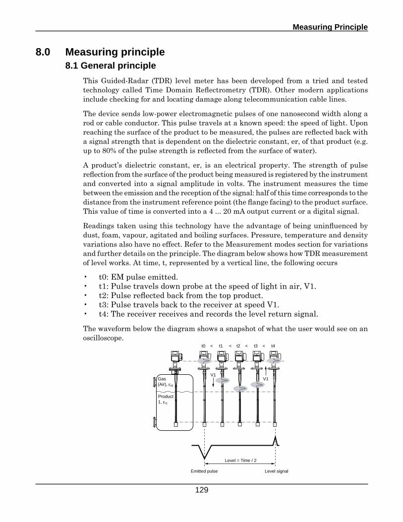
Measuring Principle
129
8.0 Measuring principle 8.1 General principle
This Guided-Radar (TDR) level meter has been developed from a tried and tested technology called Time Domain Reflectrometry (TDR). Other modern applications include checking for and locating damage along telecommunication cable lines.
The device sends low-power electromagnetic pulses of one nanosecond width along a rod or cable conductor. This pulse travels at a known speed: the speed of light. Upon reaching the surface of the product to be measured, the pulses are reflected back with a signal strength that is dependent on the dielectric constant, er, of that product (e.g. up to 80% of the pulse strength is reflected from the surface of water).
A product’s dielectric constant, er, is an electrical property. The strength of pulse reflection from the surface of the product being measured is registered by the instrument and converted into a signal amplitude in volts. The instrument measures the time between the emission and the reception of the signal: half of this time corresponds to the distance from the instrument reference point (the flange facing) to the product surface. This value of time is converted into a 4 ... 20 mA output current or a digital signal.
Readings taken using this technology have the advantage of being uninfluenced by dust, foam, vapour, agitated and boiling surfaces. Pressure, temperature and density variations also have no effect. Refer to the Measurement modes section for variations and further details on the principle. The diagram below shows how TDR measurement of level works. At time, t, represented by a vertical line, the following occurs
• t0: EM pulse emitted.• t1: Pulse travels down probe at the speed of light in air, V1.• t2: Pulse reflected back from the top product.• t3: Pulse travels back to the receiver at speed V1.• t4: The receiver receives and records the level return signal.
The waveform below the diagram shows a snapshot of what the user would see on an oscilloscope.
Product 1, εr1
Gas (Air), εr0
t0 < t1 < t2 < t3 < t4
V1V1
Level = Time / 2
Emitted pulse Level signal
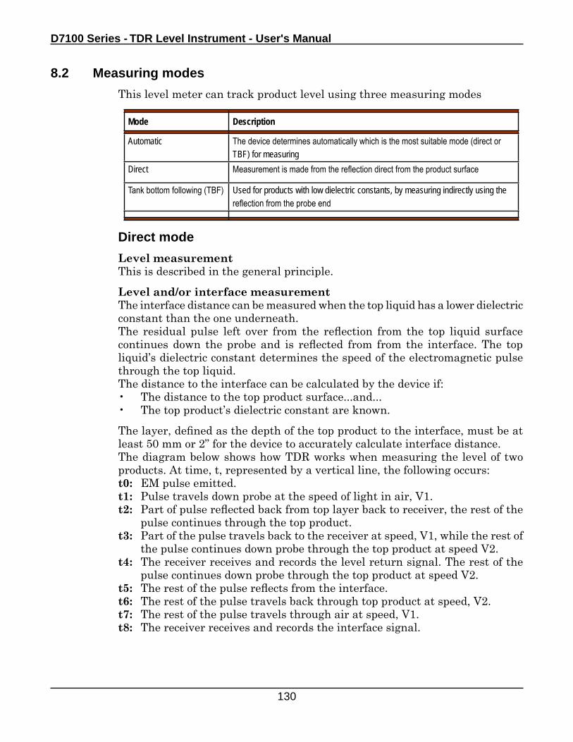
D7100 Series - TDR Level Instrument - User's Manual
130
8.2 Measuring modes
This level meter can track product level using three measuring modes
Mode Description
Automatic The device determines automatically which is the most suitable mode (direct or TBF) for measuring
Direct Measurement is made from the reflection direct from the product surface
Tank bottom following (TBF) Used for products with low dielectric constants, by measuring indirectly using the reflection from the probe end
Direct mode
Level measurementThis is described in the general principle.
Level and/or interface measurementThe interface distance can be measured when the top liquid has a lower dielectric constant than the one underneath.The residual pulse left over from the reflection from the top liquid surface continues down the probe and is reflected from from the interface. The top liquid’s dielectric constant determines the speed of the electromagnetic pulse through the top liquid. The distance to the interface can be calculated by the device if:• The distance to the top product surface...and...• The top product’s dielectric constant are known.
The layer, defined as the depth of the top product to the interface, must be at least 50 mm or 2” for the device to accurately calculate interface distance.The diagram below shows how TDR works when measuring the level of two products. At time, t, represented by a vertical line, the following occurs:t0: EM pulse emitted.t1: Pulse travels down probe at the speed of light in air, V1.t2: Part of pulse reflected back from top layer back to receiver, the rest of the
pulse continues through the top product.t3: Part of the pulse travels back to the receiver at speed, V1, while the rest of
the pulse continues down probe through the top product at speed V2.t4: The receiver receives and records the level return signal. The rest of the
pulse continues down probe through the top product at speed V2.t5: The rest of the pulse reflects from the interface.t6: The rest of the pulse travels back through top product at speed, V2.t7: The rest of the pulse travels through air at speed, V1.t8: The receiver receives and records the interface signal.
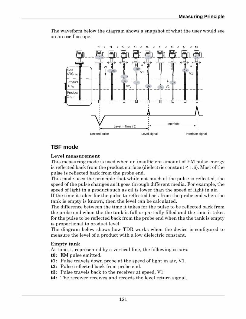
Measuring Principle
131
Product 2, εr2
Product 1, εr1
Gas (Air), εr0
t0 < t1 < t2 < t3 < t4 < t5 < t6 < t7 < t8
V1
V2
V1
V2
V1
Level = Time / 2Interface
Emitted pulse Level signal Interface signal
The waveform below the diagram shows a snapshot of what the user would see on an oscilloscope.
TBF mode
Level measurementThis measuring mode is used when an insufficient amount of EM pulse energy is reflected back from the product surface (dielectric constant < 1.6). Most of the pulse is reflected back from the probe end.This mode uses the principle that while not much of the pulse is reflected, the speed of the pulse changes as it goes through different media. For example, the speed of light in a product such as oil is lower than the speed of light in air.If the time it takes for the pulse to reflected back from the probe end when the tank is empty is known, then the level can be calculated.The difference between the time it takes for the pulse to be reflected back from the probe end when the the tank is full or partially filled and the time it takes for the pulse to be reflected back from the probe end when the the tank is empty is proportional to product level. The diagram below shows how TDR works when the device is configured to measure the level of a product with a low dielectric constant.
Empty tankAt time, t, represented by a vertical line, the following occurs:t0: EM pulse emitted.t1: Pulse travels down probe at the speed of light in air, V1.t2: Pulse reflected back from probe end.t3: Pulse travels back to the receiver at speed, V1.t4: The receiver receives and records the level return signal.
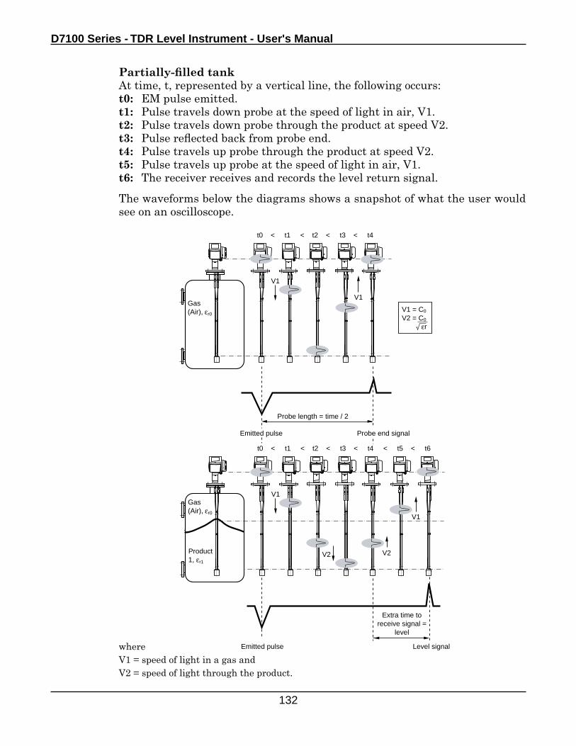
D7100 Series - TDR Level Instrument - User's Manual
132
Gas (Air), εr0
t0 < t1 < t2 < t3 < t4
V1
V1
Probe length = time / 2
Emitted pulse Probe end signal
Product 1, εr1
Gas (Air), εr0
t0 < t1 < t2 < t3 < t4 < t5 < t6
V1
V2 V2
V1
Extra time to receive signal =
level
Emitted pulse Level signal
Product 1, εr1
Gas (Air), εr0
V1 = C0
V2 = C0
εr
Partially-filled tankAt time, t, represented by a vertical line, the following occurs:t0: EM pulse emitted.t1: Pulse travels down probe at the speed of light in air, V1.t2: Pulse travels down probe through the product at speed V2.t3: Pulse reflected back from probe end.t4: Pulse travels up probe through the product at speed V2.t5: Pulse travels up probe at the speed of light in air, V1.t6: The receiver receives and records the level return signal.
The waveforms below the diagrams shows a snapshot of what the user would see on an oscilloscope.
whereV1 = speed of light in a gas andV2 = speed of light through the product.
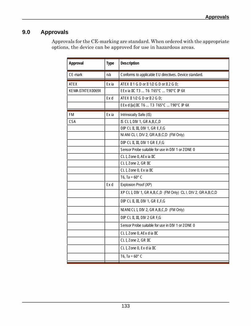
Approvals
133
9.0 Approvals
Approvals for the CE-marking are standard. When ordered with the appropriate options, the device can be approved for use in hazardous areas.
Approval Type Description
CE-mark n/a Conforms to applicable EU directives. Device standard.
ATEX Ex ia ATEX II 1 G D or II 1/2 G D or II 2 G D;KEMA 07ATEX0069X EEx ia IIC T3 … T6 T65°C … T90°C IP 6X
Ex d ATEX II 1/2 G D or II 2 G D;EEx d [ia] IIC T6 … T3 T65°C ... T90°C IP 6X
FM Ex ia Intrinsically Safe (IS)CSA IS CL I, DIV 1, GR A,B,C,D
DIP CL II, III, DIV 1, GR E,F,G NI ANI CL I, DIV 2, GR A,B,C,D (FM Only)
DIP CL II, III, DIV 1 GR E,F,GSensor Probe suitable for use in DIV 1 or ZONE 0CL I, Zone 0, AEx ia IICCL I, Zone 2, GR IICCL I, Zone 0, Ex ia IICT6, Ta = 60° C
Ex d Explosion Proof (XP)
XP CL I, DIV 1, GR A,B,C,D (FM Only) CL I, DIV 2, GR A,B,C,D
DIP CL II, III, DIV 1, GR E,F,G
NI ANI CL I, DIV 2, GR A,B,C,D (FM Only)
DIP CL II, III, DIV 2 GR F,G
Sensor Probe suitable for use in DIV 1 or ZONE 0
CL I, Zone 0, AEx d ia IICCL I, Zone 2, GR IIC
CL I, Zone 0, Ex d ia IIC
T6, Ta = 60° C

Section 10
Factory Assistance
135
Telephone Assistance
If you have questions about your AMETEK Drexelbrook equipment:
• Contact your local Drexelbrook representative
• Call the Drexelbrook Service department toll-free at: 1-800-527-6297 (US and Canada) or 215-674-1234 (Outside North America)
• Fax the following information to the Service department at: 215-443-5117.
To expedite assistance, please provide the following information:
Instrument Model Number: _______________________________________
Original Purchase order number: __________________________________
Material being measured: _________________________________________
Temperature: ____________________________________________________
Pressure: ________________________________________________________
Agitation: _______________________________________________________
Brief description of the problem: _____________________________________________________________________________________________________________________________________________________________________
Checkout procedures that have failed: ________________________________________________________________________________________________________________________________________________________________________________________________________________________________
Equipment Return / Warranty
In order to provide the best service, any equipment being returned for repair or credit must be pre-approved and have a return number issued by the factory.
In many applications, the equipment is exposed to hazardous materials.
• OSHA mandates that our employees be informed and protected from hazardous materials.
• Material Safety Data Sheets (MSDS) listing the hazardous material that the system has been exposed to must accompany any return.
• It is your responsibility to fully disclose all chemicals and decontaminate the returned items.
10.0 Factory Assistance
D7100 Series - TDR Level Instrument - User's Manual
136
Equipment Return (Continued)
To obtain a return authorization number (RA#), contact the Service department at:1-800-527-6297 (US and Canada) or 215-674-1234 (Outside North America).
Please provide the following information:
Model Number of Returned Equipment: ____________________________
Serial Number: __________________________________________________
Original Purchase Order Number: _________________________________
Process Material that the equipment has been exposed: _____________
MSDS for any hazardous materials
Billing Address: __________________________________________________
Shipping Address: ________________________________________________
Purchase Order Number for Repairs: ______________________________
Please include a purchase order number even if the repair is under warranty. If repair is covered under warranty, you will not be charged.
Ship equipment freight prepaid to:AMETEK Drexelbrook205 Keith Valley RoadHorsham, PA 19044
COD shipments will not be accepted.
AMETEK Drexelbrook warrants its products free of material defects or manufacturing defects for a period of 1 year after date of shipment.
Field Service
Trained field service personnel are available on a time-plus-expense basis to assist in start-ups, diagnosing difficult application or equipment problems, or in-plant training of personnel. Preventive Maintenance and Calibration Certification service contracts are also available to maintain plant efficiency. Contact the Service department for further information.
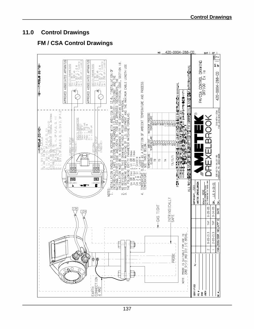
Control Drawings
137
11.0 Control Drawings
FM / CSA Control Drawings
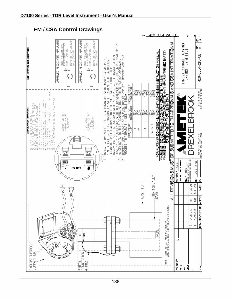
D7100 Series - TDR Level Instrument - User's Manual
138
FM / CSA Control Drawings
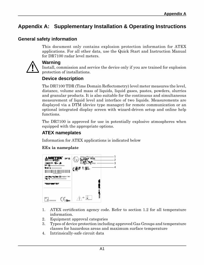
Appendix A
A1
Appendix A: Supplementary Installation & Operating Instructions
General safety information This document only contains explosion protection information for ATEX applications. For all other data, use the Quick Start and Instruction Manual for DR7100 radar level meters.
WarningInstall, commission and service the device only if you are trained for explosion protection of installations.
Device description
The DR7100 TDR (Time Domain Reflectometry) level meter measures the level, distance, volume and mass of liquids, liquid gases, pastes, powders, slurries and granular products. It is also suitable for the continuous and simultaneous measurement of liquid level and interface of two liquids. Measurements are displayed via a DTM (device type manager) for remote communication or an optional integrated display screen with wizard-driven setup and online help functions.
The DR7100 is approved for use in potentially explosive atmospheres when equipped with the appropriate options.
ATEX nameplates
Information for ATEX applications is indicated below
EEx ia nameplate
1. ATEX certification agency code. Refer to section 1.2 for all temperature information.
2. Equipment approval categories3. Types of device protection including approved Gas Groups and temperature
classes for hazardous areas and maximum surface temperature4. Intrinsically-safe circuit data
1234
IP6X
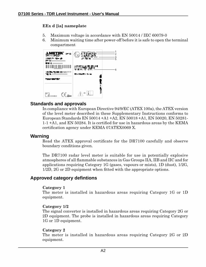
D7100 Series - TDR Level Instrument - User's Manual
A2
EEx d [ia] nameplate
5. Maximum voltage in accordance with EN 50014 / IEC 60079-06. Minimum waiting time after power-off before it is safe to open the terminal
compartment1235
6
Standards and approvalsIn compliance with European Directive 94/9/EC (ATEX 100a), the ATEX version of the level meter described in these Supplementary Instructions conforms to European Standards EN 50014 +A1 +A2, EN 50018 +A1, EN 50020, EN 50281- 1-1 +A1, and EN 50284. It is certified for use in hazardous areas by the KEMA certification agency under KEMA 07ATEX0069 X.
WarningRead the ATEX approval certificate for the DR7100 carefully and observe boundary conditions given.
The DR7100 radar level meter is suitable for use in potentially explosive atmospheres of all flammable substances in Gas Groups IIA, IIB and IIC and for applications requiring Category 1G (gases, vapours or mists), 1D (dust), 1/2G, 1/2D, 2G or 2D equipment when fitted with the appropriate options.
Approved category defintions
Category 1The meter is installed in hazardous areas requiring Category 1G or 1D equipment.
Category 1/2The signal converter is installed in hazardous areas requiring Category 2G or 2D equipment. The probe is installed in hazardous areas requiring Category 1G or 1D equipment.
Category 2The meter is installed in hazardous areas requiring Category 2G or 2D equipment.
IP6X
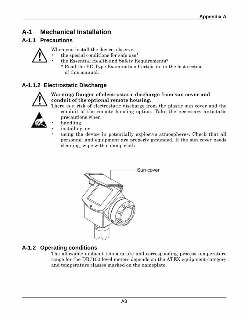
Appendix A
A3
A-1 Mechanical InstallationA-1.1 Precautions
When you install the device, observe• the special conditions for safe use*• the Essential Health and Safety Requirements* * Read the EC-Type Examination Certificate in the last section of this manual.
A-1.1.2 Electrostatic Discharge
Warning: Danger of electrostatic discharge from sun cover and conduit of the optional remote housing.There is a risk of electrostatic discharge from the plastic sun cover and the
conduit of the remote housing option. Take the necessary antistatic precautions when
• handling• installing, or• using the device in potentially explosive atmospheres. Check that all
personnel and equipment are properly grounded. If the sun cover needs cleaning, wipe with a damp cloth.
A-1.2 Operating conditionsThe allowable ambient temperature and corresponding process temperature range for the DR7100 level meters depends on the ATEX equipment category and temperature classes marked on the nameplate.
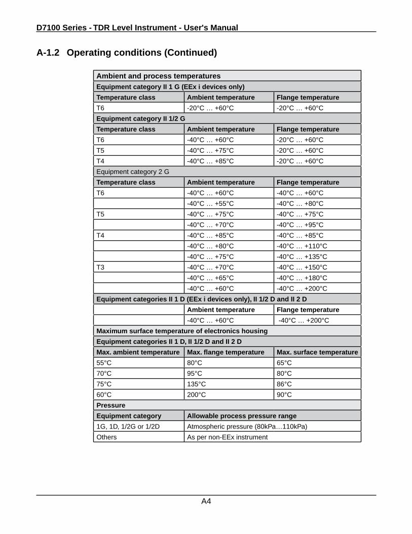
D7100 Series - TDR Level Instrument - User's Manual
A4
Ambient and process temperaturesEquipment category II 1 G (EEx i devices only)
Temperature class Ambient temperature Flange temperature
T6 -20°C … +60°C -20°C … +60°C
Equipment category II 1/2 G
Temperature class Ambient temperature Flange temperature
T6 -40°C … +60°C -20°C … +60°C
T5 -40°C … +75°C -20°C … +60°C
T4 -40°C … +85°C -20°C … +60°C
Equipment category 2 G
Temperature class Ambient temperature Flange temperature
T6 -40°C … +60°C -40°C … +60°C
-40°C … +55°C -40°C … +80°C
T5 -40°C … +75°C -40°C … +75°C
-40°C … +70°C -40°C … +95°C
T4 -40°C … +85°C -40°C … +85°C
-40°C … +80°C -40°C … +110°C
-40°C … +75°C -40°C … +135°C
T3 -40°C … +70°C -40°C … +150°C
-40°C … +65°C -40°C … +180°C
-40°C … +60°C -40°C … +200°C
Equipment categories II 1 D (EEx i devices only), II 1/2 D and II 2 D
Ambient temperature Flange temperature
-40°C … +60°C -40°C … +200°C
Maximum surface temperature of electronics housing
Equipment categories II 1 D, II 1/2 D and II 2 D
Max. ambient temperature Max. flange temperature Max. surface temperature
55°C 80°C 65°C
70°C 95°C 80°C
75°C 135°C 86°C
60°C 200°C 90°C
Pressure
Equipment category Allowable process pressure range
1G, 1D, 1/2G or 1/2D Atmospheric pressure (80kPa…110kPa)
Others As per non-EEx instrument
A-1.2 Operating conditions (Continued)
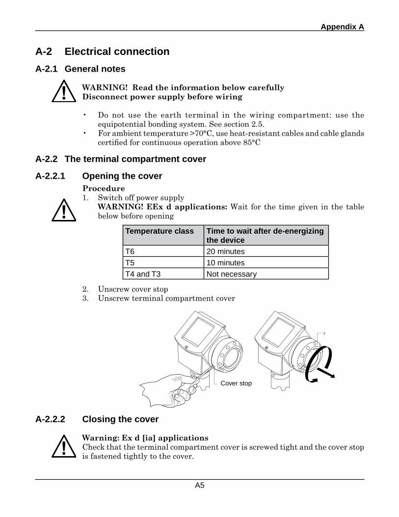
Appendix A
A5
A-2 Electrical connection
A-2.1 General notes
WARNING! Read the information below carefullyDisconnect power supply before wiring
• Do not use the earth terminal in the wiring compartment: use the equipotential bonding system. See section 2.5.
• For ambient temperature >70°C, use heat-resistant cables and cable glands certified for continuous operation above 85°C
A-2.2 The terminal compartment cover
A-2.2.1 Opening the cover
b
c
Procedure1. Switch off power supply WARNING! EEx d applications: Wait for the time given in the table
below before opening
Cover stop
A-2.2.2 Closing the cover
Warning: Ex d [ia] applicationsCheck that the terminal compartment cover is screwed tight and the cover stop is fastened tightly to the cover.
Temperature class Time to wait after de-energizing the device
T6 20 minutesT5 10 minutesT4 and T3 Not necessary
2. Unscrew cover stop3. Unscrew terminal compartment cover
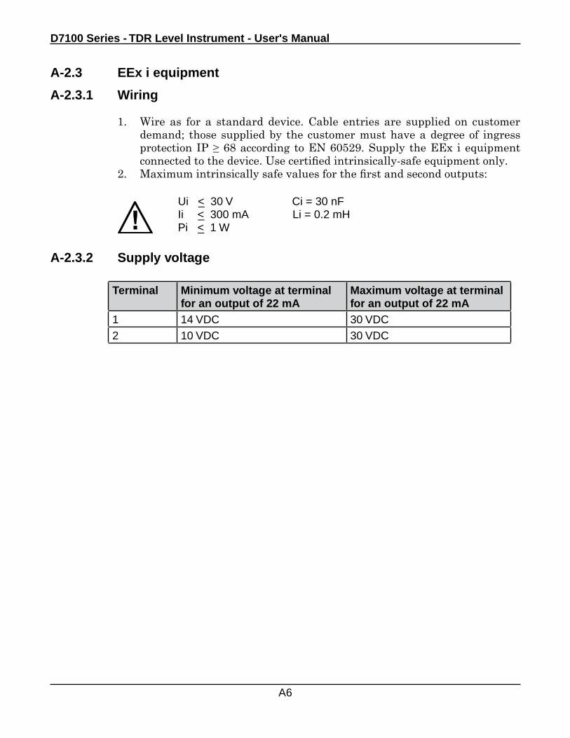
D7100 Series - TDR Level Instrument - User's Manual
A6
A-2.3 EEx i equipment
A-2.3.1 Wiring
1. Wire as for a standard device. Cable entries are supplied on customer demand; those supplied by the customer must have a degree of ingress protection IP ≥ 68 according to EN 60529. Supply the EEx i equipment connected to the device. Use certified intrinsically-safe equipment only.
2. Maximum intrinsically safe values for the first and second outputs:
Ui <_ 30 V Ci = 30 nFIi <_ 300 mA Li = 0.2 mHPi <_ 1 W
A-2.3.2 Supply voltage
Terminal Minimum voltage at terminal for an output of 22 mA
Maximum voltage at terminal for an output of 22 mA
1 14 VDC 30 VDC2 10 VDC 30 VDC
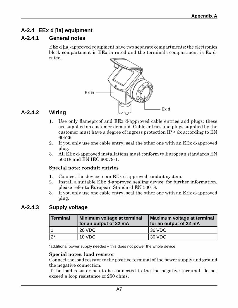
Appendix A
A7
A-2.4 EEx d [ia] equipmentA-2.4.1 General notes
EEx d [ia]-approved equipment have two separate compartments: the electronics block compartment is EEx ia-rated and the terminals compartment is Ex d-rated.
A-2.4.3 Supply voltage
Special notes: load resistorConnect the load resistor to the positive terminal of the power supply and ground the negative connection.If the load resistor has to be connected to the the negative terminal, do not exceed a loop resistance of 250 ohms.
*additional power supply needed – this does not power the whole device
Terminal Minimum voltage at terminal for an output of 22 mA
Maximum voltage at terminal for an output of 22 mA
1 20 VDC 36 VDC2* 10 VDC 30 VDC
A-2.4.2 Wiring
1. Use only flameproof and EEx d-approved cable entries and plugs: these are supplied on customer demand. Cable entries and plugs supplied by the customer must have a degree of ingress protection IP ≥ 6x according to EN 60529.
2. If you only use one cable entry, seal the other one with an EEx d-approved plug.
3. All EEx d-approved installations must conform to European standards EN 50018 and EN IEC 60079-1.
Special note: conduit entries
1. Connect the device to an EEx d-approved conduit system.2. Install a suitable EEx d-approved sealing device: for further information,
please refer to European Standard EN 50018.3. If you only use one cable entry, seal the other one with an EEx d-approved
plug.
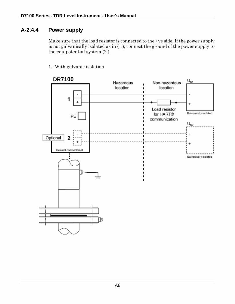
D7100 Series - TDR Level Instrument - User's Manual
A8
A-2.4.4 Power supply
Make sure that the load resistor is connected to the +ve side. If the power supply is not galvanically isolated as in (1.), connect the ground of the power supply to the equipotential system (2.).
1. With galvanic isolation
DR7100
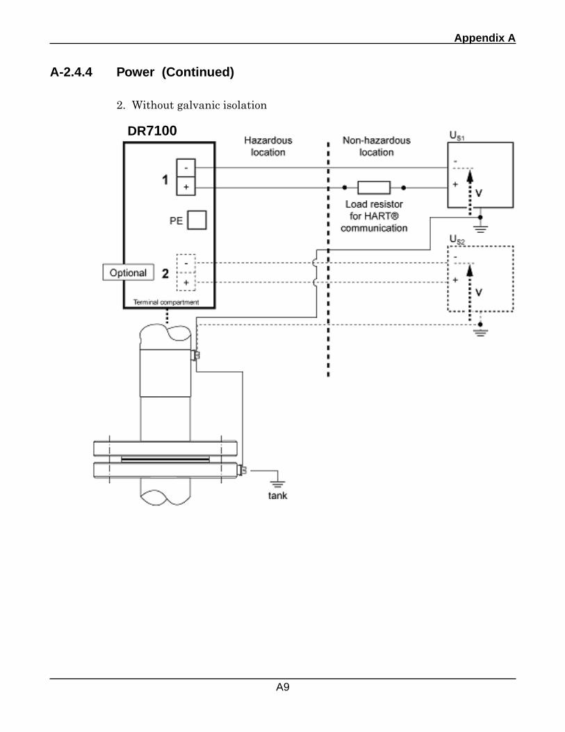
Appendix A
A9
2. Without galvanic isolation
A-2.4.4 Power (Continued)
DR7100
D7100 Series - TDR Level Instrument - User's Manual
A10
A-3 Commissioning
Start-up checklist
Do not connect power until you have gone through the checklist below
1. Are the wetted components (gasket, flange and probe) resistant to the corrosive properties of the tank product?
2. Does the information given on the nameplate correspond with the application?
3. Have you connected the equipotential bonding system correctly?4. EEx d applications: Are the cable entries, plugs and adaptors EEx d-
approved?5. EEx i applications: Are you using an intrinsic barrier within the correct
parameters? Refer to section 2.3 for the maximum intrinsically safe values for the electrical circuit.
6. Did you install cable entries of the correct internal diameter so that there is a good seal around the cable?
A-4 Service and maintenance
Maintenance in hazardous areas can ony be carried out by• the manufacturer• a Drexelbrook-authorized representative• technicians under the supervision of authorized inspectors
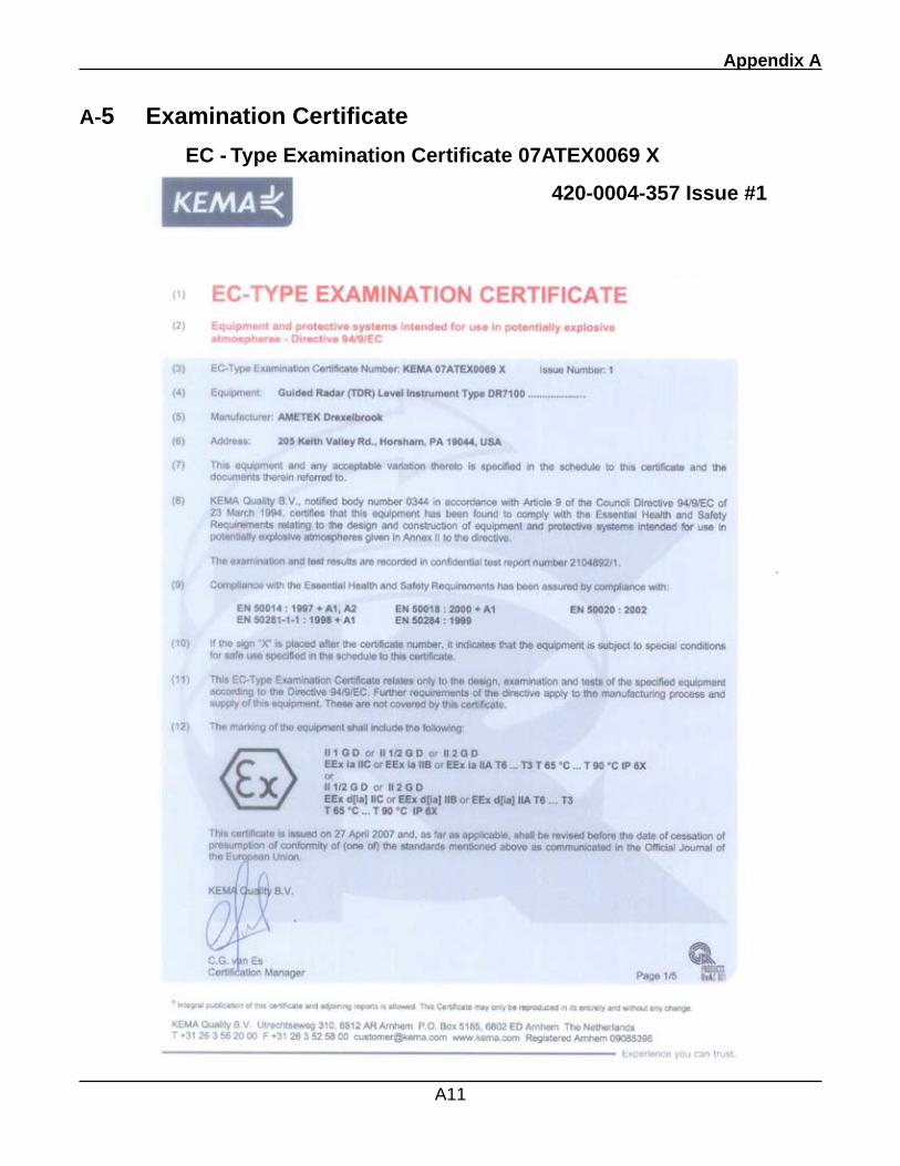
Appendix A
A11
A-5 Examination Certificate
EC - Type Examination Certificate 07ATEX0069 X
420-0004-357 Issue #1
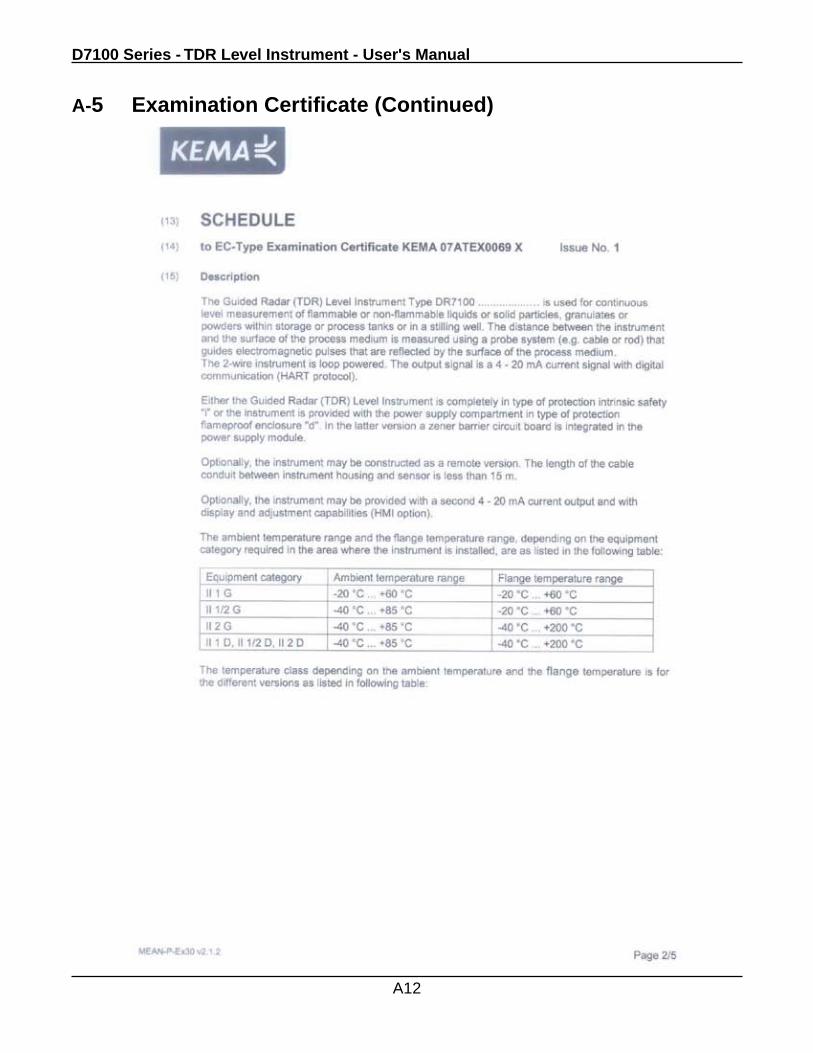
D7100 Series - TDR Level Instrument - User's Manual
A12
A-5 Examination Certificate (Continued)
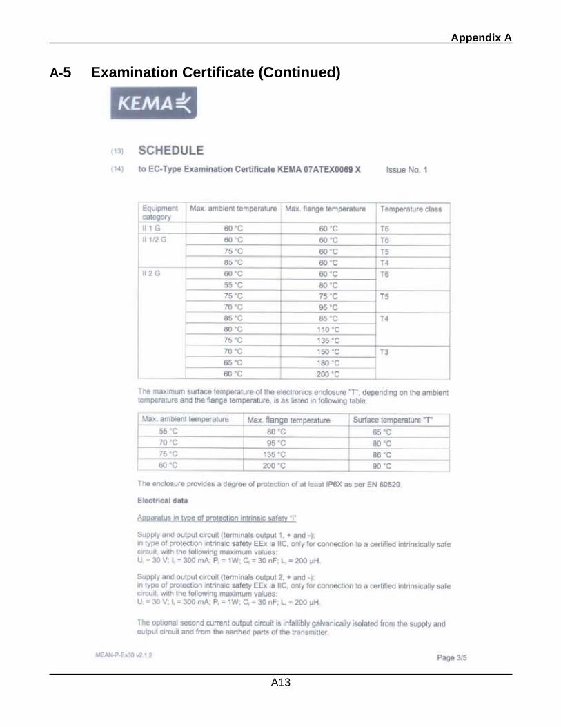
Appendix A
A13
A-5 Examination Certificate (Continued)
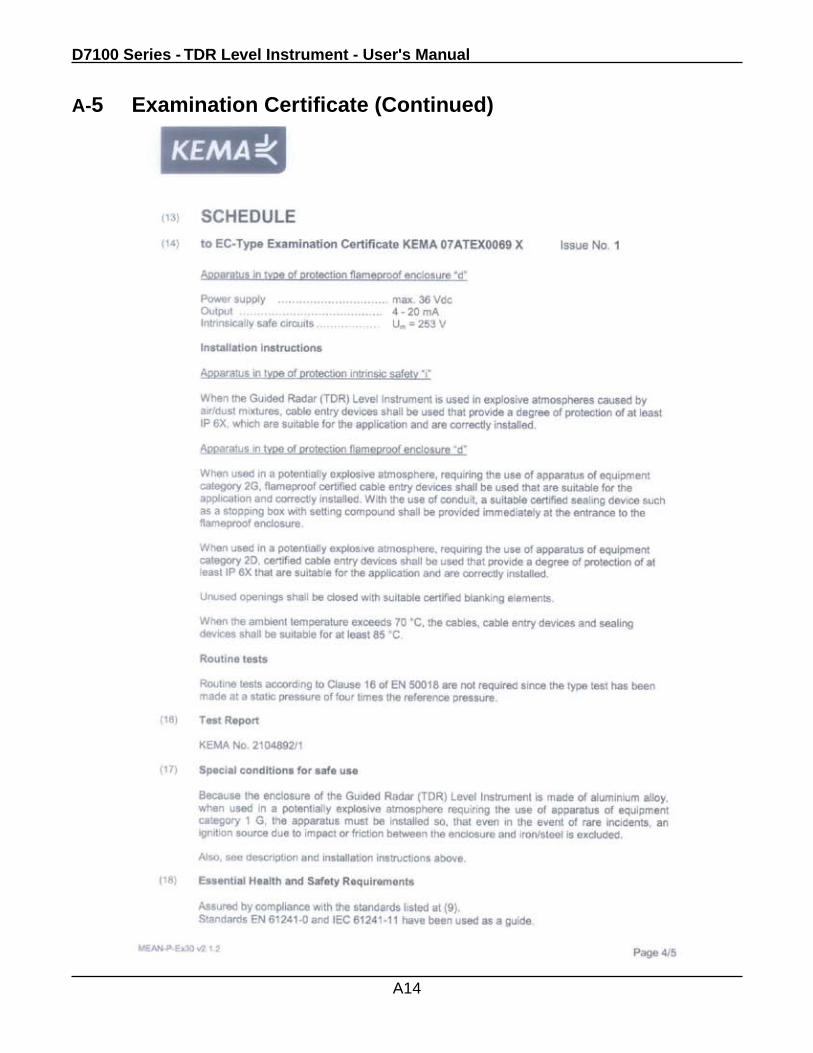
D7100 Series - TDR Level Instrument - User's Manual
A14
A-5 Examination Certificate (Continued)
Appendix A
A15
A-5 Examination Certificate (Continued)
Form 440-0001-001 3/1/2006
TERMS AND CONDITIONS OF SALEGENERAL: ALL ORDERS ARE SUBJECT TO THE FOLLOWING TERMS AND CONDITIONS. ANY ACCEPTANCE OF ANY OFFER OF BUYER FOR ANY GOODS OR SERVICES IS CONDITIONED UPON THESE TERMS AND CONDITIONS, AND SELLER OBJECTS TO ANY ADDITIONAL OR DIFFERENT TERMS PROPOSED BY BUYER IN ANY DOCUMENT, WHICH SHALL NOT BE BINDING UPON SELLER. No salesman or other party is authorized to bind the AMETEK DREXELBROOK Division of AMETEK, Inc. (hereinafter “Seller”) by any agreement, warranty, statement, promise, or understanding not herein expressed, and no modifications shall be binding on Seller unless the same are in writing and signed by an executive officer of Seller or his or her duly authorized representative. Verbal orders shall not be executed until written notification has been received and acknowledged by Seller.
QUOTATIONS: Written quotations are valid for thirty (30) days unless otherwise stated. Verbal quotations expire the same day they are made.
PRICES: All prices and terms are subject to change without notice. Buyer-requested changes to its order (“Orders”), including those affecting the identity, scope and delivery of the goods or services, must be documented in writing and are subject to Seller’s prior approval and adjustments in price, schedule and other affected terms and conditions. Orders requiring certified test data in excess of commercial requirements, are subject to a special charge.
ORDER ACCEPTANCE: All Orders are subject to final approval and acceptance by Seller at its office located at 205 Keith Valley Road, Horsham, Pennsylvania 19044.
TERMS OF PAYMENT: Seller’s standard terms of payment for Buyers who qualify for credit are net thirty (30) days from date of invoice. All invoices must be paid in United States dollars.
CREDIT: Seller reserves the right at any time to revoke any credit extended to Buyer or otherwise modify terms of payment if Buyer fails to pay for any shipments when due or if in Seller’s opinion there is a material adverse change in Buyer’s financial condition. Seller may, at its option, cancel any accepted Order if Buyer fails to pay any invoices when due.
DELIVERY: Shipments are F.O.B place of manufacture (“Shipping Point”) and the Buyer shall pay all freight, transportation, shipping, duties, fees, handling, insurance, storage, demurrage, or similar charges from Shipping Point. Delivery of goods to common carrier shall constitute delivery and passing of title to the Buyer, and all risk of loss or damage in transit shall be borne by Buyer. Any claims or losses for damage or destruction after such delivery shall be the responsibility of Buyer.
Seller reserves the right to make delivery in installments which shall be separately invoiced and paid for when due, without regard to subsequent deliveries. Delay in delivery of any installment shall not relieve Buyer of its obligation to accept remaining deliveries.
Acknowledged shipping dates are approximate only and based on prompt receipt of all necessary information from Buyer and Buyer’s compliance with terms of payment.
TAXES: All sales, excise and similar taxes which Seller may be required to pay or collect with respect to the goods and/or services covered by any Order, shall be for the account of the Buyer except as otherwise provided by law or unless specifically stated otherwise by Seller in writing.
TERMINATION AND HOLD ORDERS: No Order may be terminated by Buyer except upon written request by Buyer and approval by Seller, and if said request is approved by Seller, under the following conditions: (1) Buyer agrees to accept delivery of all of the units completed by Seller through the workday on which Seller receives the written termination request; (2) Buyer agrees to pay to Seller all direct costs and expenses applicable to the portion of the Order that is incomplete.
WARRANTY: A. Hardware: Seller warrants its goods against defects in materials and workmanship under normal use and service for one (1) year from the date of invoice. B. Software and Firmware: Unless otherwise specified, Seller warrants for a period of one (1) year from date of invoice that standard software or firmware, when used with Seller specified hardware, shall perform in accordance with Seller’s published specifications. Seller makes no representation or warranty, expressed or implied, that the operation of the software or firmware shall be uninterrupted or error-free, or that functions contained therein shall meet or satisfy the Buyer’s intended use or requirements. C. Services: Seller warrants that services, including engineering and custom application, whether provided on a fixed cost or time and material basis, shall be performed in accordance with generally accepted industry practices. D. Remedies: Seller’s liability under this section is restricted to replacing, repairing, or issuing credit (at Seller’s option) for any returned goods and only under the following conditions: (1) Seller must be promptly notified, in writing, as soon as possible after the defects have been noted by the Buyer, but not later than (1) year from date of invoice from Seller; (2) The defective goods are to be returned to the place of manufacture, shipping charges prepaid by the Buyer; (3) Seller’s inspection shall disclose to its satisfaction that the goods were defective in materials or workmanship at the time of shipment; (4) Any warranty service (consisting of time, travel and expenses related to such services) performed other than at Seller’s factory, shall be at Buyer’s expense. E.Repaired/Reconditioned Goods: As to out-of-warranty goods which Seller has repaired or reconditioned, Seller warrants for a period of sixty (60) days from date of its invoice only new components replaced in the most recent repair/reconditioning. F. Returns and Adjustments: No goods may be returned unless authorized in advance by Seller and then only upon such conditions to which Seller may agree. Buyer must obtain an RMA (Return Material Authorization) number from Seller prior to any return shipment and such RMA number must appear on the shipping label and packing slip. Buyer shall be responsible for the returned goods until such time as Seller receives the same at its plant and for all charges for packing, inspection, shipping, transportation, or insurance associated with returned goods. In the event that credit for returned goods is granted, it shall be at the lesser of the then current prices or the original purchase price. Claims for shortage or incorrect material must be made within five (5) days after receipt of shipment.
ALL OTHER WARRANTIES, FOR ANY OF SELLER’S GOODS OR SERVICES, WHETHER ORAL, WRITTEN, EXPRESS, IMPLIED, STATUTORY OR OTHERWISE, INCLUDING WITHOUT LIMITATION ANY IMPLIED WARRANTY OF MERCHANTABILITY OR FITNESS FOR PURPOSE ARE EXCLUDED.
INTELLECTUAL PROPERTY: Seller’s sale of goods or provision of related documentation or other materials to Buyer shall not transfer any intellectual property rights to Buyer unless Seller specifically agrees to do so in writing. Seller shall retain ownership of all applicable patents, trademarks, copyrights and other intellectual property rights. Buyer shall not use, copy or transfer any such items in violation of Seller’s intellectual property rights or applicable law, or for any purposes other than that for which the items were furnished.
Seller shall defend any lawsuit brought against the Buyer based on a claim that the design or construction of the goods sold hereunder by Seller infringe any United States or Canadian Patent, Copyright or Mask Work Registration, provided that Buyer promptly notifies Seller of such claim in writing and further provided that, at Seller’s expense, (1) Buyer gives Seller the sole right to defend or control the defense of the suit or proceeding, including settlement, and (2) Buyer provides all necessary information and assistance for that defense. In the event of a charge of infringement, Seller’s obligation under the agreement shall be fulfilled if Seller, at its option and expense, either (i) settles such claim; (ii) procures for Buyer the right to continue using such goods; (iii) replaces or modifies goods to avoid infringement; or (iv) accepts the return of any infringing goods and refunds their purchase price; or (iv) defends against such claim.
If Buyer furnishes specifications or designs to Seller, the obligations of Seller set forth above shall not apply to goods made by Seller using such specifications or designs, and Buyer shall defend, indemnify and hold Seller harmless against any third party claims for infringement which arise out of Seller’s use of specifications or designs furnished by Buyer.
SOFTWARE LICENSE: If goods purchased hereunder include software (“Software”), Buyer may use the Software only as part of the goods. Buyer may not use, copy, or transfer any of the Software except as may be permitted under the applicable License Agreement provided with the goods. Buyer’s right to use, copy or transfer the Software shall terminate upon termination of Buyer’s right to use the goods.
PACKAGING/WEIGHTS AND DIMENSIONS: Buyer specified packing or marking may be subject to additional charges not otherwise included in the price of the goods. Published weights and dimensions are estimates or approximate only and are not warranted.
FORCE MAJEURE: Seller shall not be responsible for delays in delivery or any failure to deliver due to causes beyond Seller’s control, including but not limited to the following items: acts of God, war, terrorism, mobilization, civil commotion, riots, embargoes, domestic or foreign governmental regulations or orders, governmental priorities, port congestion, acts of the Buyer, its agents or employees, fires, floods, strikes, lockouts and other labor difficulties, shortages of or inability to obtain shipping space or transportation, inability to secure fuel, supplies or power at current prices or on account of shortages thereof, or due to limitations imposed by the extent of availability of Seller’s normal manufacturing facilities.
If a delay excused per the above extends for more than ninety (90) days and the parties have not agreed upon a revised basis for continuing providing the goods or services at the end of the delay, including adjustment of the price, then Buyer, upon thirty (30) days’ prior written notice to Seller may terminate the Order with respect to the unexecuted portion of the goods or services, whereupon Buyer shall promptly pay Seller its reasonable termination charges upon submission of Seller’s invoices thereof.
LIMITATION OF LIABILITY: Seller’s liability for any claim of any kind, except infringement of intellectual property rights, shall not exceed the purchase price of any goods or services which give rise to the claim. SELLER SHALL IN NO EVENT BE LIABLE FOR BUYER’S MANUFACTURING COSTS, LOST PROFITS, LOSS OF USE OF THE GOODS OR SERVICES, COST OF CAPITAL, COST OF SUBSTITUTE GOODS, FACILITIES, SERVICES OR REPLACEMENT POWER, DOWNTIME COSTS, CLAIMS OF BUYER’S CUSTOMERS FOR DAMAGES, OR OTHER SPECIAL, PROXIMATE, INCIDENTAL, INDIRECT, EXEMPLARY OR CONSEQUENTIAL DAMAGES. Any action against Seller must be brought within eighteen (18) months after the cause of action accrues. These disclaimers and limitations of liability shall apply regardless of the form of action, whether in contract, tort or otherwise, and further shall extend to the benefit of Seller’s vendors, appointed distributors and other authorized resellers as third-party beneficiaries.
PROHIBITION FOR HAZARDOUS USE: Goods sold hereunder generally are not intended for application in and shall not be used by Buyer in the construction or operation of a nuclear installation or in connection with the use or handling of nuclear material, or for any hazardous activity or critical application, where failure of a single component could cause substantial harm to persons or property, unless the goods have been specifically approved for such a use or application. Seller disclaims all liability for any loss or damage resulting from such unauthorized use and Buyer shall defend, indemnify and hold harmless the Seller against any such liability, whether as a result of breach of contract, warranty, tort (regardless of the degree of fault or negligence), strict liability or otherwise.
EXPORT CONTROL: Buyer shall comply with all export control laws and regulations of the United States, and all sales hereunder are subject to those laws and regulations. Seller shall not be named as shipper or exporter of record for any goods sold hereunder unless specifically agreed to in writing by Seller. At Seller’s request, Buyer shall furnish Seller with end-use and end-user information to determine export license applicability. Buyer warrants, in accordance with U.S. Export Law, that goods sold hereunder shall not be destined for facilities or activities involving nuclear, chemical or biological weapons, or related missile delivery systems in named prohibited regions or countries.
GOVERNING LAW: Seller intends to comply with all laws applicable to its performance under any order. All matters relating to interpretation and effect of these terms and any authorized changes, modifications or amendments thereto shall be governed by the laws of the Commonwealth of Pennsylvania. No government contract regulations or clauses shall apply to the goods or services, this agreement, or act to bind Seller unless specifically agreed to by Seller in writing.
NON-WAIVER BY SELLER: Waiver by Seller of a breach of any of these terms and conditions shall not be construed as a waiver of any other breach.
SEVERABILITY AND ENTIRE AGREEMENT: If any provision of these terms and conditions is unenforceable, the remaining terms shall nonetheless continue in full force and effect. This writing, together with any other terms and conditions Seller specifically agrees to in writing, constitutes the entire terms and conditions of sale between Buyer and Seller and supercedes any and all prior discussions, and negotiations on its subject matter.


205 Keith Valley Road, Horsham, PA 19044 U.S. and Canada: 1-800-553-909224-Hour Service: 1-800-527-6297International: +1 215-674-1234Fax: +1 215-674-2731E-mail: [email protected] Website: www.drexelbrook.com
An ISO 9001 Certified Company