Embed Size (px)
Citation preview
Edition: 12/09
British Autogard Limited
Cirencester, Glos., GL7 1YT UK Tel. +44 (0)1285 640333 – Fax. +44 (0)1285 659476
USA +1 815 229 3190 � Japan +81 3 3449 9621 � Germany +49 5261 921 258
� Australia +61 3 9532 0901 � Italy +39 0292 1700 471
Registered Number 4380334 England
Installation and Maintenance
Instructions
AUTOGARD SERIES 400 TORQUE LIMITER
Edition: 12/09 Page 2 of 35
Contents 1. Technical Data
1.1 Standard Parts List 3
1.2 General Technical Data 4
1.2.1 Size 1 – 5 4-5
1.2.2 Size 6 – 9 6-7
1.3 Other Models (402 / 405 / 406) 8-12
2. General Notes
2.1 General 13
3. Safety Notes
3.1 Safety Notes 13-14
3.2 Notes used in the Operation Instructions 14
4. Handling and Storage
4.1 Scope of supply 15
4.2 Handling 15
4.3 Storage 15
5. Technical description
5.1 General description 16
5.2 Torque Transmission 16
5.3 Disengagement process 17
5.4 Reengagement 17
6. Installation
6.1 Finish boring 17
6.2 Securing axially 17
6.3 Balancing 17
6.4 General installation notes 18
6.5 Mounting a sprocket, gear or pulley 18
6.6 Mounting torque limiter on shaft. 18
7. Startup 7.1 Measures prior to startup 19
7.2 Torque adjustment 19
7.2.1 Torque adjustment with Sizes 1 – 5 19-20
7.2.2 Torque adjustment with Sizes 6 – 9 20-23
8. Operation
8.1 General data 23
9. Troubleshooting
9.1 General 24
9.2 Normal operation
9.3 Troubleshooting guide 24-25
10. Maintenance and servicing
10.1 General 26
10.2 Disassembly of sizes 1-5 26-27
10.3 Assembly of sizes 1 – 5 28-30
10.4 Disassembly of sizes 6 – 9 30-31
10.5 Assembly of Sizes 6 – 9 32-34
10.6 Lubricants 34
11. Spare parts & Service 34-35
11.1 Addresses of spare parts stockists and service facilities 35
Edition: 12/09 Page 3 of 35
1. Technical Data
1.1 Standard parts (Figure 1)
Part
Number
Description Spares
Code
Part
Number
Description Spares
code
21 Hub B 42 Pawl B
22 Slide plate B 43 Tape journal bearing A
23 Adjusting nut C 44 Tape thrust bearing A
24 Strut ring C 45 Adapter ball bearing B
25 Drive plate B 46 Cage plate spring C
26 Cage plate B 52 Clamp collar C
27 Calibration spacer C 53 Adjustment spacer C
28 Adapter C 54 Adjuster screw C
29 Pawl spring A 55 Washer C
30 Torque spring outer
(spring stack > size 5)
C 56 Spring pillar C
31 Torque spring inner C 57 Ball bearing (SR strut
ring only)
A
32 Drive balls A 58 Switch plate / cover B
33 Needle thrust bearing A 59 Switch plate fixing
screw
B
34 - 60 Felt strip – switch
plate cover
A
35 Roll pin for SR pawl B 61 Drive plate cover B
36 Stop pin outer B 62 Felt strip – drive plate
cover
A
37 Adapter bolt A 63 -
38 - 64 Locking peg C
39 Adapter dowel pin A 65 Locking peg screw C
40 Adjusting nut locking
screw
A 66 -
41 Stop pin inner B 67 Bearing spacer C
Spares Codes:
A = Standard service item – spares stock is recommended
B = Potential service item – spares stock is recommended in critical applications
C= Spares stock is not normally required
For details of specifications, part number and quantities required for specific sizes and models, please contact
Autogard or visit www.autogard.com where full arrangement drawings and parts lists are available.
Edition: 12/09 Page 4 of 35
1.2 General Technical Data
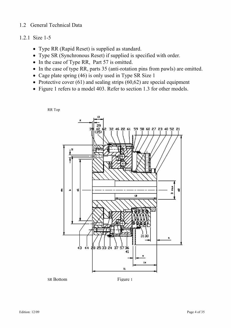
1.2.1 Size 1-5
• Type RR (Rapid Reset) is supplied as standard. • Type SR (Synchronous Reset) if supplied is specified with order. • In the case of Type RR, Part 57 is omitted.
• In the case of type RR, parts 35 (anti-rotation pins from pawls) are omitted.
• Cage plate spring (46) is only used in Type SR Size 1 • Protective cover (61) and sealing strips (60,62) are special equipment
• Figure 1 refers to a model 403. Refer to section 1.3 for other models.
RR Top
SR Bottom Figure 1
Edition: 12/09 Page 5 of 35
Size
Max
Torque
Setting Tmax Nm
Speed
(3)
Nmax
1/min
Dmax
mm
da
mm
d1
mm
d2
mm
x
mm
z
mm
k
mm
s
lB
mm
l1
mm
l3
mm
l4 (1)
mm
Wt.
(2)
kg
1 28 3000 16 62 30 110 1.5 1.5 41.3 5xM4 30 59 9.2 22.4 1
2 225 3000 28 112 75 140 2.8 4.8 92 6xM8 50 108 15.8 43.7 5.5
3 680 3000 40 146 95 184 3.5 4.8 114 7xM10 70 114 15.8 44.7 10.5
4 1130 2000 50 168 122 203 3.5 4.8 144 8xM12 75 121 15.8 45.9 15
5 2540 2000 75 222 155 280 4.4 6.4 184 8xM16 110 163 25.4 68.9 36
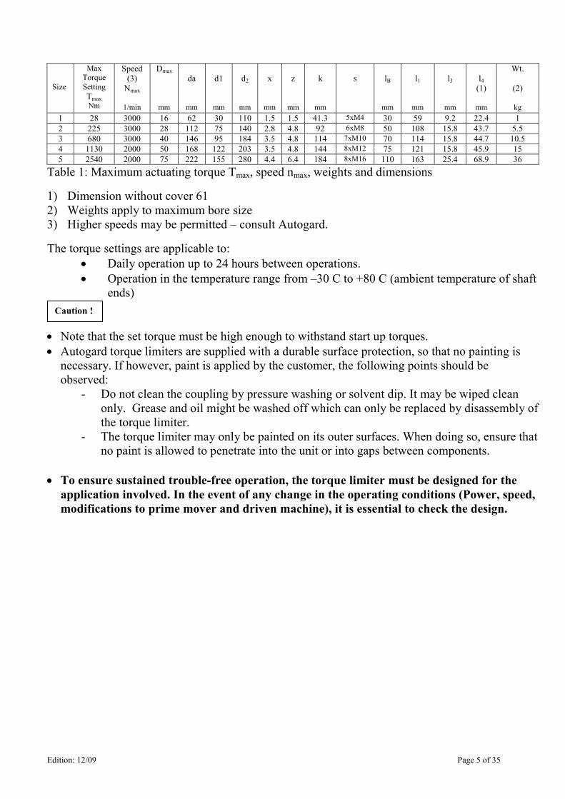
Table 1: Maximum actuating torque Tmax, speed nmax, weights and dimensions
1) Dimension without cover 61
2) Weights apply to maximum bore size
3) Higher speeds may be permitted – consult Autogard.
The torque settings are applicable to:
• Daily operation up to 24 hours between operations.
• Operation in the temperature range from –30 C to +80 C (ambient temperature of shaft
ends)
• Note that the set torque must be high enough to withstand start up torques.
• Autogard torque limiters are supplied with a durable surface protection, so that no painting is
necessary. If however, paint is applied by the customer, the following points should be
observed:
- Do not clean the coupling by pressure washing or solvent dip. It may be wiped clean
only. Grease and oil might be washed off which can only be replaced by disassembly of
the torque limiter.
- The torque limiter may only be painted on its outer surfaces. When doing so, ensure that
no paint is allowed to penetrate into the unit or into gaps between components.
• To ensure sustained trouble-free operation, the torque limiter must be designed for the application involved. In the event of any change in the operating conditions (Power, speed,
modifications to prime mover and driven machine), it is essential to check the design.
Caution !
Edition: 12/09 Page 6 of 35
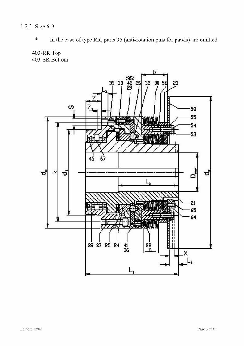
1.2.2 Size 6-9
* In the case of type RR, parts 35 (anti-rotation pins for pawls) are omitted
403-RR Top
403-SR Bottom
Edition: 12/09 Page 7 of 35
Size Max
Torque
Setting
Tmax Nm
Speed
Nmax
1/min
Dmax
mm
da
mm
D1
J6
Mm
d2
mm
w
mm
x
mm
z
mm
k
mm
s
lB
mm
l1
mm
l3
mm
l4
mm
Wt.
(1)
kg
6 5650 1500 100 263 200 304.8 9.5 5.3 36.5 228 9x M16
150 217 24 79 55
7 8600
11300
1500
1500
125 480
520
265
295
406.4 12.7 6.3 6 440
480
10x
M20 210 245 35 87.3 125
140
8 13800
17600
24850
1000
1000
1000
150
575
615
655
325
355
370
476.2
NA
8.1
8
528
568
608
10x
M24
240
300
38
120 225
235
250
9 31600
40800
56500
1000
1000
950
175
730
780
830
410
440
480
546.1
NA
10
8
670
720
770
10x M30
270
410
40
158 530
550
570
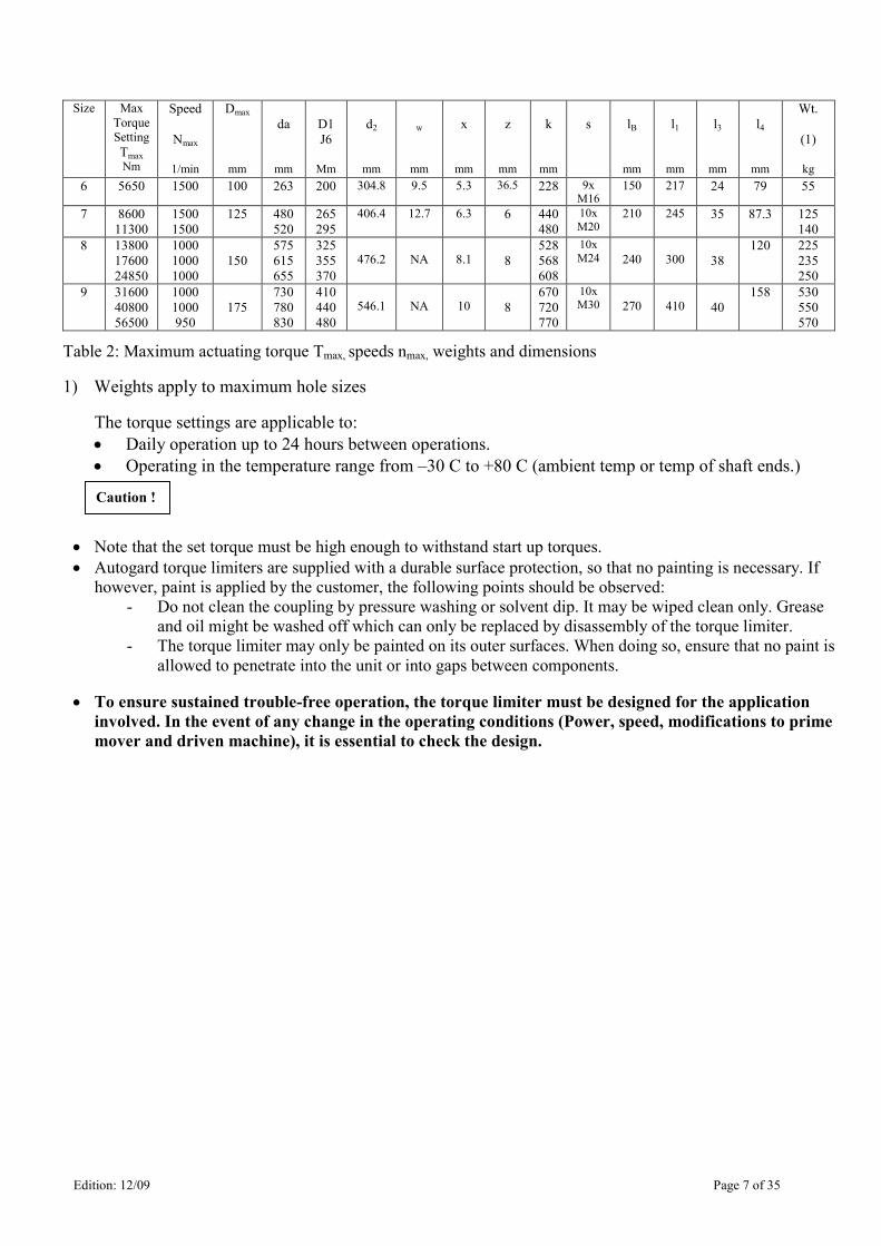
Table 2: Maximum actuating torque Tmax, speeds nmax, weights and dimensions
1) Weights apply to maximum hole sizes
The torque settings are applicable to:
• Daily operation up to 24 hours between operations.
• Operating in the temperature range from –30 C to +80 C (ambient temp or temp of shaft ends.)
• Note that the set torque must be high enough to withstand start up torques.
• Autogard torque limiters are supplied with a durable surface protection, so that no painting is necessary. If
however, paint is applied by the customer, the following points should be observed:
- Do not clean the coupling by pressure washing or solvent dip. It may be wiped clean only. Grease
and oil might be washed off which can only be replaced by disassembly of the torque limiter.
- The torque limiter may only be painted on its outer surfaces. When doing so, ensure that no paint is
allowed to penetrate into the unit or into gaps between components.
• To ensure sustained trouble-free operation, the torque limiter must be designed for the application involved. In the event of any change in the operating conditions (Power, speed, modifications to prime
mover and driven machine), it is essential to check the design.
Caution !
Edition: 12/09 Page 8 of 35
1.3 Other Models
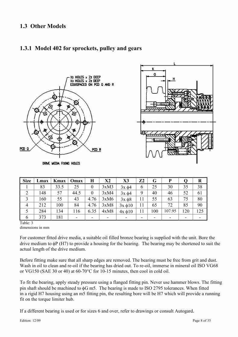
1.3.1 Model 402 for sprockets, pulley and gears
Size Lmax Kmax Omax H X2 X3 Z2 G P Q R
1 83 33.5 25 0 3xM3 3x φ4 6 25 30 35 38
2 148 57 44.5 0 3xM4 3x φ4 9 40 46 52 61
3 160 55 43 4.76 3xM6 3x φ8 11 55 63 75 80
4 212 100 84 4.76 3xM8 3x φ10 11 65 72 85 90
5 284 134 116 6.35 4xM8 4x φ10 11 100 107.95 120 125
6 373 181 - - - - - - - - - Table: 3
dimensions in mm
For customer fitted drive media, a suitable oil filled bronze bearing is supplied with the unit. Bore the
drive medium to φP (H7) to provide a housing for the bearing. The bearing may be shortened to suit the
actual length of the drive medium.
Before fitting make sure that all sharp edges are removed. The bearing must be free from grit and dust.
Wash in oil to clean and re-oil if the bearing has dried out. To re-oil, immerse in mineral oil ISO VG68
or VG150 (SAE 30 or 40) at 60-70°C for 10-15 minutes, then cool in cold oil.
To fit the bearing, apply steady pressure using a flanged fitting pin. Never use hammer blows. The fitting
pin shaft should be machined to φG m5. The bearing is made to ISO 2795 tolerances. When fitted
in a rigid H7 housing using an m5 fitting pin, the resulting bore will be H7 which will provide a running
fit on the torque limiter hub.
If a different bearing is used or for sizes 6 and over, refer to drawings or consult Autogard.
Edition: 12/09 Page 9 of 35
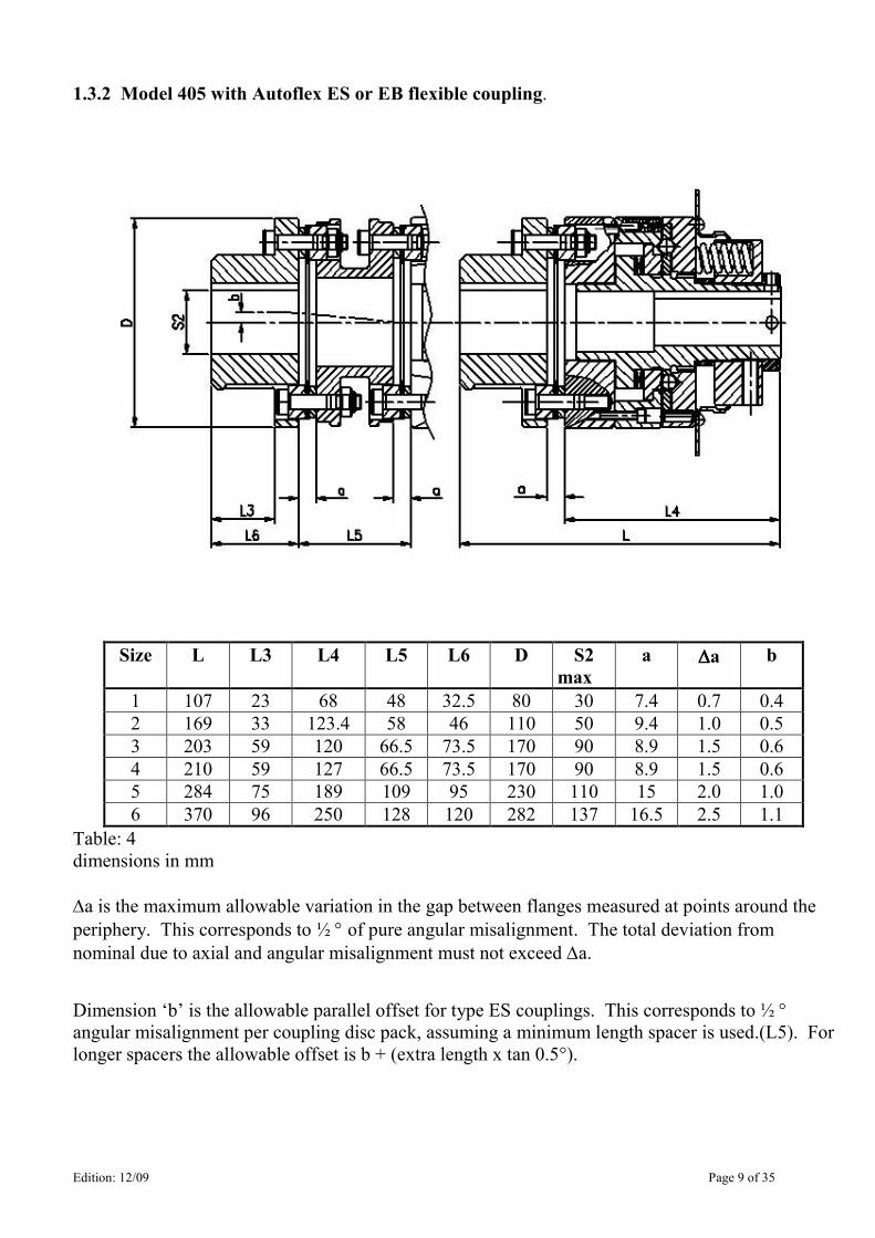
1.3.2 Model 405 with Autoflex ES or EB flexible coupling.
Size L L3 L4 L5 L6 D S2
max
a ∆∆∆∆a b
1 107 23 68 48 32.5 80 30 7.4 0.7 0.4
2 169 33 123.4 58 46 110 50 9.4 1.0 0.5
3 203 59 120 66.5 73.5 170 90 8.9 1.5 0.6
4 210 59 127 66.5 73.5 170 90 8.9 1.5 0.6
5 284 75 189 109 95 230 110 15 2.0 1.0
6 370 96 250 128 120 282 137 16.5 2.5 1.1
Table: 4
dimensions in mm
∆a is the maximum allowable variation in the gap between flanges measured at points around the
periphery. This corresponds to ½ ° of pure angular misalignment. The total deviation from
nominal due to axial and angular misalignment must not exceed ∆a.
Dimension ‘b’ is the allowable parallel offset for type ES couplings. This corresponds to ½ ° angular misalignment per coupling disc pack, assuming a minimum length spacer is used.(L5). For
longer spacers the allowable offset is b + (extra length x tan 0.5°).
Edition: 12/09 Page 10 of 35
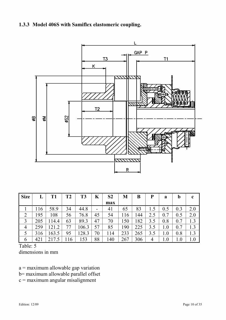
1.3.3 Model 406S with Samiflex elastomeric coupling.
Size L T1 T2 T3 K S2
max
M B P a b c
1 116 58.9 34 44.8 - 41 65 83 1.5 0.5 0.3 2.0
2 195 108 56 76.8 45 54 116 144 2.5 0.7 0.5 2.0
3 205 114.4 63 89.3 47 70 150 182 3.5 0.8 0.7 1.3
4 259 121.2 77 106.3 57 85 190 225 3.5 1.0 0.7 1.3
5 316 163.5 95 128.3 70 114 233 265 3.5 1.0 0.8 1.3
6 421 217.5 116 153 88 140 267 306 4 1.0 1.0 1.0
Table: 5
dimensions in mm
a = maximum allowable gap variation
b= maximum allowable parallel offset
c = maximum angular misalignment
Edition: 12/09 Page 11 of 35
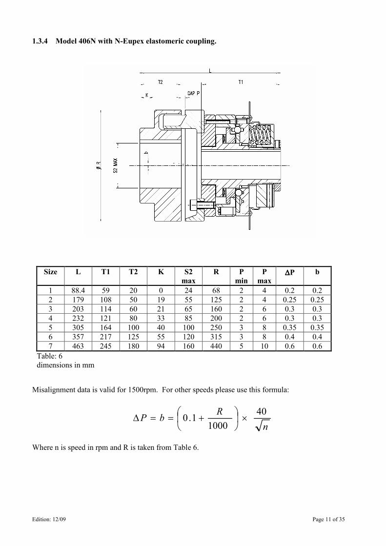
1.3.4 Model 406N with N-Eupex elastomeric coupling.
Size L T1 T2 K S2
max
R P
min
P
max ∆∆∆∆P b
1 88.4 59 20 0 24 68 2 4 0.2 0.2
2 179 108 50 19 55 125 2 4 0.25 0.25
3 203 114 60 21 65 160 2 6 0.3 0.3
4 232 121 80 33 85 200 2 6 0.3 0.3
5 305 164 100 40 100 250 3 8 0.35 0.35
6 357 217 125 55 120 315 3 8 0.4 0.4
7 463 245 180 94 160 440 5 10 0.6 0.6
Table: 6
dimensions in mm
Misalignment data is valid for 1500rpm. For other speeds please use this formula:
n
RbP
40
10001.0 ×
+==∆
Where n is speed in rpm and R is taken from Table 6.
Edition: 12/09 Page 12 of 35
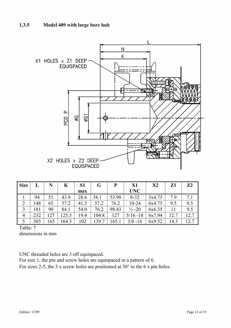
1.3.5 Model 409 with large bore hub
Size L N K S1
max
G P X1
UNC
X2 Z1 Z2
1 94 51 43.9 28.6 38.1 53.98 8-32 3x4.75 7.9 7.1
2 148 65 57.2 41.3 57.2 76.2 10-24 6x4.75 9.5 9.5
3 181 90 84.1 54.0 76.2 98.43 ½ -20 6x6.35 11 9.5
4 232 127 125.5 19.4 104.8 127 5/16 -18 6x7.94 12.7 12.7
5 303 165 164.3 102 139.7 165.1 3/8 -16 6x9.52 14.3 12.7
Table: 7
dimensions in mm
UNC threaded holes are 3 off equispaced.
For size 1, the pin and screw holes are equispaced in a pattern of 6.
For sizes 2-5, the 3 x screw holes are positioned at 30° to the 6 x pin holes.
Edition: 12/09 Page 13 of 35
2. General Notes
2.1 General
These Operating Instructions constitute part of the torque limiter supply. They should be kept in the
vicinity of the torque limiter at all times.
Only precise knowledge of the Operating Instructions will ensure trouble-free operation of the coupling.
It is therefore in the interest of the customer for the Operating Instructions to be read, understood and
observed in all respects by the persons responsible for handling, assembly and operation.
Note: We assume no liability for damage resulting from non-observance of the Operating Instructions.
The Torque Limiter dealt with in these Operating Instructions has been designed for use in general
engineering. It is intended for use in protecting industrial machinery and is not to be regarded as a safety
device.
The torque limiter described here is in accordance with the state of the art at the time of printing these
Operating Instructions.
In the interest of further development, we reserve the right to introduce modifications which we consider
appropriate, while retaining the essential features, to increase efficiency and reliability.
All technical questions should be referred to Autogard at,
British Autogard Ltd Telephone: +44 (0)1285 640333
Cirencester Facimile: +44 (0)1285 659476
e-mail: [email protected]
or to one of our Service Facilities. A list of the Service Facilities will be found in Section 11.
3. Safety Notes
3.1 Safety Notes
• The Torque Limiter is constructed in accordance with the state of the art and is reliable in the state
as shipped. Unauthorized modifications which impair reliability are not permissible. This also
applies to safety devices which are fitted as protection against accidental contact.
• The Torque Limiter may only be used and operated under the conditions specified in the
performance and supply contract.
• The customer has to ensure that the persons entrusted with installation, operation care and
maintenance, as well as repair, have read and understood these Operating Instructions and observe
them in all respects in order:
- To prevent hazard to life and limb on the part of the user and third parties.
- To ensure the reliability of the Torque Limiter.
- To prevent failure and environmental contamination resulting from improper handling.
- To comply with essential health and safety requirements.
Edition: 12/09 Page 14 of 35
3.1 Safety Notes - Continued
• During the course of handling, assembly and disassembly, operation, as well as care and
maintenance, the relevant regulations regarding industrial safety and pollution control are to be
observed.
• The coupling may only be operated, maintained and repaired by authorised, trained and suitably
supervised personnel.
• All work should be carried out with due care and with the safety aspect in mind.
• Work on the coupling may only be carried when it is stationary. The drive unit must be isolated to
prevent accidental start-up (for example by locking the key switch or removing the fuses from the
power supply). A notice should be affixed to the start-up point stating that work on the Torque
Limiter is in progress.
• During operation, the drive unit should be shut off immediately if changes in the torque limiter are
detected, such as for example changes in operating noises.
• The torque limiter must be protected to prevent accidental contact by means of a suitable guard.
• When the torque limiter is installed in equipment or systems, the manufacturer of the equipment or
systems is obliged to include the instructions, notes and description contained in these Operating
Instructions in his own Operating Instructions.
• It is the responsibility of the manufacturer of the equipment or system to ensure that local codes of
safety are complied with. (e.g. EC Safety of Machinery Regulations in Europe).
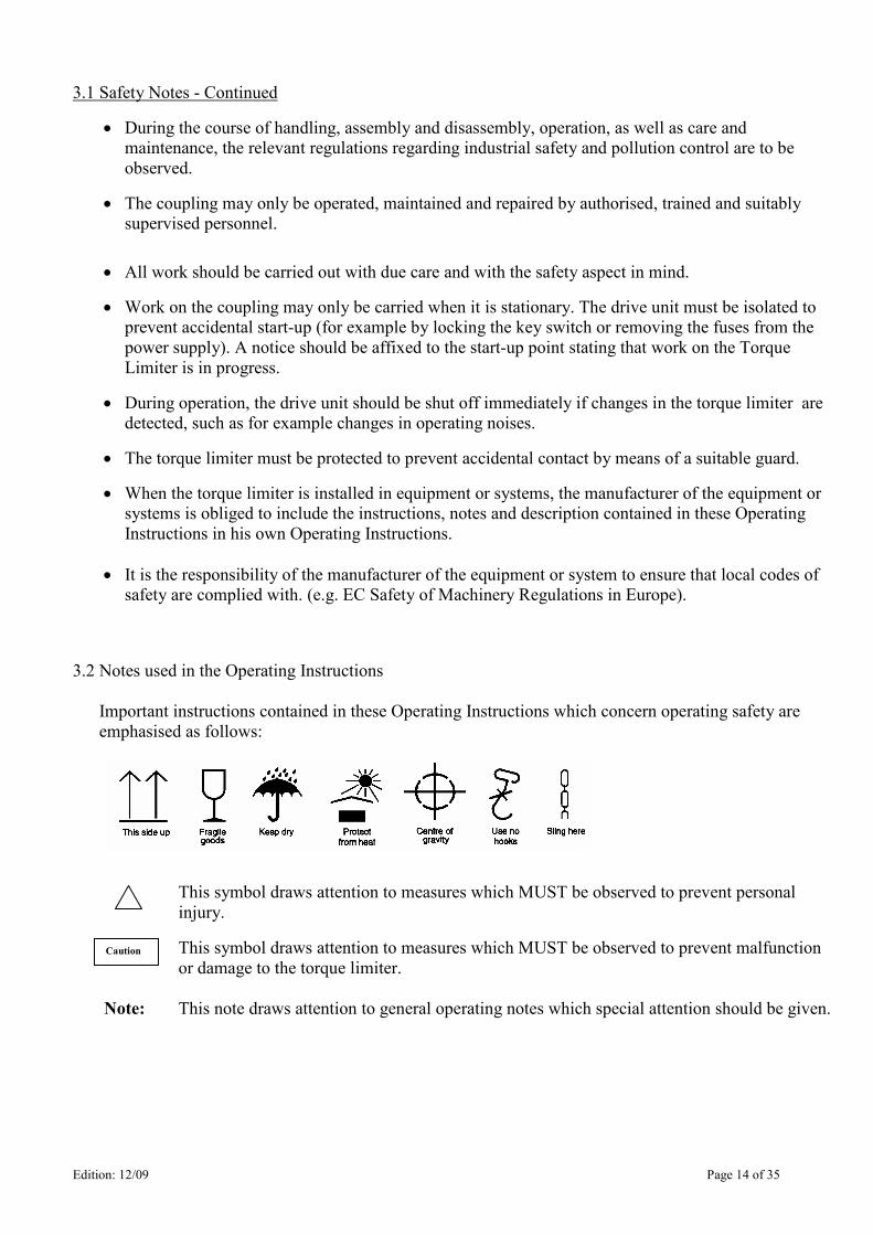
3.2 Notes used in the Operating Instructions
Important instructions contained in these Operating Instructions which concern operating safety are
emphasised as follows:
This symbol draws attention to measures which MUST be observed to prevent personal
injury.
This symbol draws attention to measures which MUST be observed to prevent malfunction
or damage to the torque limiter.
Note: This note draws attention to general operating notes which special attention should be given.
Caution
Edition: 12/09 Page 15 of 35
4. Handling and Storage
4.1 Scope of supply
The scope of supply of the shipment is listed in the despatch documents. It should be checked
for completeness on receipt. Any shipping damage and/or missing parts should be reported
immediately in writing.
4.2 Handling
Packing of the torque limiter will differ, dependent on methods of shipment and size. The
packing will, unless agreed to the contrary, comply with Autogard standards.
The symbols applied to the packing should be noted. Their significance is as follows:
Ensure that a suitable hoist is used
4.3 Storage
Autogard torque limiters are supplied manganese-phosphated and oiled and can be stored in a
dry place for long periods of time. In the case of prolonged storage, the torque limiter should
be covered to prevent excessive contamination. Long-term preservation is only necessary for
the finish bore.
If dirty, the torque limiter MUST be cleaned. However, avoid complete wash
down as this can wash oil and grease out of the interior of the torque limiter,
necessitating complete disassembly and re-lubrication.
Caution
Caution
Edition: 12/09 Page 16 of 35
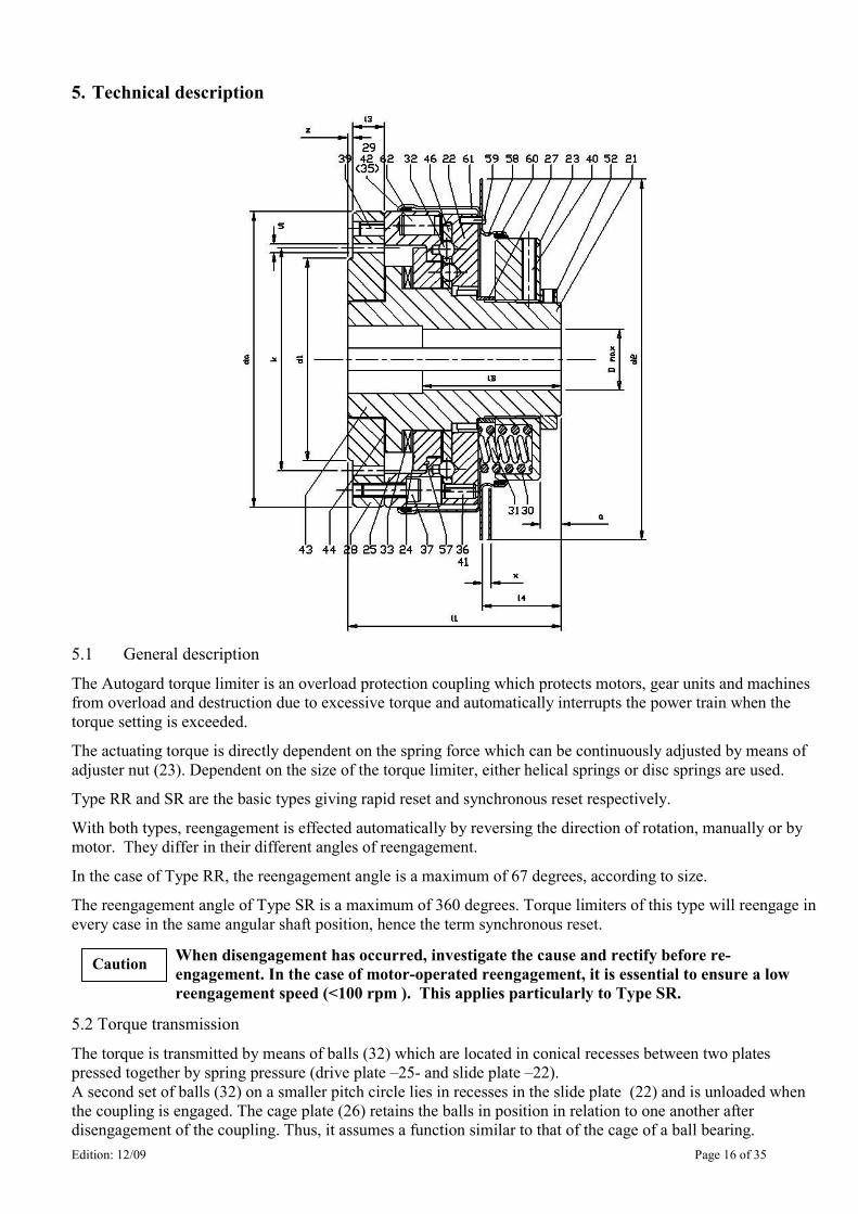
5. Technical description
5.1 General description
The Autogard torque limiter is an overload protection coupling which protects motors, gear units and machines
from overload and destruction due to excessive torque and automatically interrupts the power train when the
torque setting is exceeded.
The actuating torque is directly dependent on the spring force which can be continuously adjusted by means of
adjuster nut (23). Dependent on the size of the torque limiter, either helical springs or disc springs are used.
Type RR and SR are the basic types giving rapid reset and synchronous reset respectively.
With both types, reengagement is effected automatically by reversing the direction of rotation, manually or by
motor. They differ in their different angles of reengagement.
In the case of Type RR, the reengagement angle is a maximum of 67 degrees, according to size.
The reengagement angle of Type SR is a maximum of 360 degrees. Torque limiters of this type will reengage in
every case in the same angular shaft position, hence the term synchronous reset.
When disengagement has occurred, investigate the cause and rectify before re-
engagement. In the case of motor-operated reengagement, it is essential to ensure a low
reengagement speed (<100 rpm ). This applies particularly to Type SR.
5.2 Torque transmission
The torque is transmitted by means of balls (32) which are located in conical recesses between two plates
pressed together by spring pressure (drive plate –25- and slide plate –22).
A second set of balls (32) on a smaller pitch circle lies in recesses in the slide plate (22) and is unloaded when
the coupling is engaged. The cage plate (26) retains the balls in position in relation to one another after
disengagement of the coupling. Thus, it assumes a function similar to that of the cage of a ball bearing.
Caution
Edition: 12/09 Page 17 of 35
5.3 Disengagement process
When the running torque reaches a value which exceeds the set torque, the balls (32) of the outer pitch circle roll
under load out of their recesses. The disengagement process is now commenced and the drive path between input
and output sides of the drive is completely interrupted.
At the same time, the balls of the inner pitch circle are also rolled out of their recesses by the cage plate (26).
Then, the slide plate (22) and the drive plate (25) rotate in relation to one another until the outer balls (32) engage
in recesses (or escape seats) which are only present in the slide plate. Apart from any minimal residual torque,
caused by the friction in the journal bearings (43 and 44), no further torque is transmitted.
The balls (32) of the inner pitch circle are now positioned between ball seats and support the full load generated
by the springs (30 & 31). They maintain the slide plate (22) and the drive plate (25) at a distance by resting
against the strut ring (24). The balls on the outer pitch circle, previously responsible for torque transmission, are
at this moment unloaded. A pin (36) in the slide plate (22) prevents any further rotation of the slide plate in
relation to the cage plate (26). Reengagement of the outer balls in their recesses is prevented and as a result the
drive plate (25) can rotate freely on the hub. As a result of the disengagement of the torque limiter, the slide plate
(22) moves axially and with it, the limit switch plate (58). This axial movement (x) should be monitored with a
limit switch or a proximity switch.
Series 400 Autogard torque limiters should be monitored with a limit switch or a proximity switch in
order to prevent unnecessary wear. Although these couplings can run for some time in the disengaged
state, periods exceeding several minutes should be avoided (particularly with high-speed drive units).
5.4 Reengagement
Re-engagement takes place automatically as a result of reversing the direction of rotation of the drive unit or of
the output drive continuing to rotate with the drive motor stationary. When this happens, one of the spring-loaded
pawls (29) extends by following a ramp on the slide plate (22) into a cut out in the cage plate (46) and turns the
latter back until the balls (32) align with their original recesses in the drive plate. At this point, the pawl is forced
back into its hole in the drive plate (25) by a second ramp on the slide plate (22). The slide plate then continues to
rotate relative to the cage and drive plates until the slide plate seats are aligned with the balls. The mechanism
then snaps back into re-engagement.
Resetting must be done at low speed (<100rpm) to permit the engaging mechanism to function
properly in either direction and to prevent potential damage. It should be done manually or
by slowly inching the motor in reverse. Other methods are possible but it is essential to ensure
slow differential speed between input and output during re-setting.
6. Installation
6.1 Finish boring. Autogard torque limiters are normally supplied bored and keywayed. Couplings without bore and keyway
cannot be set to an exact actuating torque. Please contact Autogard for advise.
6.2 Securing axially on the shaft. The coupling halves are secured by means of setscrews (cup point) or with and end plate and central locking
screw.
The length of the setscrews should be such that it fills the tapped hole, but does not project past
the outside diameter (Lmin=setscrew diam x 1.2). 6.3 Balancing
Autogard torque limiters are generally supplied without special balancing. If a special application (for example
high rpm and large coupling size) necessitates balancing or it is required by the customer, this balancing can be
carried out at our works and must be specified at the time of order. Type SR must be specified if the unit is to be
balanced.
Caution
Caution
Edition: 12/09 Page 18 of 35
6.4 General installation notes
During installation, the Safety Notes in Section 3 should be observed. Installation should be carried out with extreme care by specialist personnel. Ensure right at the planning stage that there is adequate space available for
installation and subsequent care and maintenance. Adequate hoists must be available when installation is
commenced.
6.5 Mounting a sprocket, gear or pulley (Models 402, 409)
If not supplied with the unit, a sprocket, gear or pulley may be mounted by bolting to the adaptor. Fixing
dimensions are given in tables 3 and 7.
In the case of Model 402, a bearing is supplied, which the customer may fit in the sprocket, gears or pulley. The
required boring dimensions are given in the table. The bearing may be shortened to suit.
For 402 size 6 and above a suitable bearing must be supplied by the customer.
For 409, the customer should supply and fit their own bearing to suit the dimensions shown in Table 7.
It is essential that fixing bolts or pins do not protrude through the adapter and interfere
with the internal mechanism of the torque limiter.
Please select all bolts and pin lengths carefully.
6.6 Mounting Torque Limiter on the Shaft
Before commencing installation, the shaft ends and the torque limiter bores should be carefully cleaned.
Avoid oil and grease being washed out of the interior of the torque limiter; this will necessitate complete
disassembly and re-lubrication.
6.6.1 Models 402, 409
With the torque limiter completely assembled, carefully engage the hub bore on the shaft. The standard
clearance fit bore should permit the hub to be pushed or lightly tapped in place on the shaft.
Do not strike with heavy hammer blows on the hub. On no account must direct heat be
applied to the torque limiter.
Once on the shaft, the torque limiter should be moved axially to obtain proper alignment of the sprocket,
gear or pulley. Once in position, tighten the set screws.
6.6.2 Models 405, 406 Mount the torque limiter on one shaft as described in 6.6.1. Mount the in-line coupling hub to the other shaft
in a similar manner. Bring the shafts together and assemble the coupling, observing the shaft alignment
requirements shown in tables 4, 5 and 6.
6.6.3 Models 403 For Model 403, the driven member is supplied by the customer. If used for an offset drive, the sprocket, pulley
or gear must be mounted on its own bearing. If a coupling hub is fitted, follow the manufacturer’s
recommendations for alignment.
Nonobservance of these notes can lead to torque limiter damage and in extreme cases
break up of parts. Flying fragments are a serious hazard and must be prevented.
Caution
Caution
Edition: 12/09 Page 19 of 35
7. Startup
7.1 Before startup, the tightness of the setscrews should be checked and the coupling guard fitted.
7.2 Torque adjustment
Autogard torque limiters are supplied set to a fixed torque value in accordance with the customer’s
requirements if specified at time of order, otherwise it will be set near minimum trip torque. If the exact
actuating torque cannot be determined beforehand, an actuating torque range can also be stated.
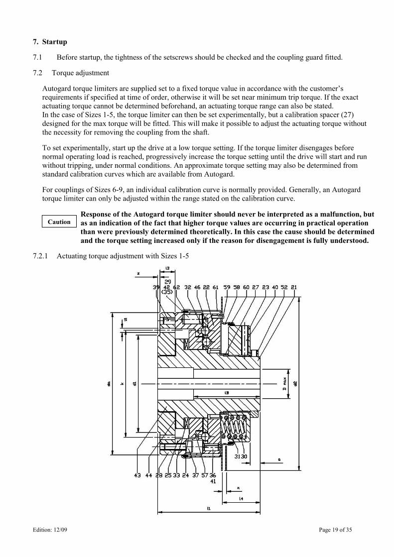
In the case of Sizes 1-5, the torque limiter can then be set experimentally, but a calibration spacer (27)
designed for the max torque will be fitted. This will make it possible to adjust the actuating torque without
the necessity for removing the coupling from the shaft.
To set experimentally, start up the drive at a low torque setting. If the torque limiter disengages before
normal operating load is reached, progressively increase the torque setting until the drive will start and run
without tripping, under normal conditions. An approximate torque setting may also be determined from
standard calibration curves which are available from Autogard.
For couplings of Sizes 6-9, an individual calibration curve is normally provided. Generally, an Autogard
torque limiter can only be adjusted within the range stated on the calibration curve.
Response of the Autogard torque limiter should never be interpreted as a malfunction, but
as an indication of the fact that higher torque values are occurring in practical operation
than were previously determined theoretically. In this case the cause should be determined
and the torque setting increased only if the reason for disengagement is fully understood.
7.2.1 Actuating torque adjustment with Sizes 1-5
Caution
Edition: 12/09 Page 20 of 35
ON NO ACCOUNT should calibration spacers (27) be removed, as otherwise no guarantee can
be given of disengagement of the coupling. Replacement of springs with a stronger or weaker
set, and shortening the calibration sleeve are ONLY permissible with the EXPRESS approval
of Autogard.
• First of all, the locking screws (40) of the adjusting nut (23) should be slackened. These locking screws
prevent accidental rotation of the adjusting nut during operation.
• Increasing the set torque;
- The torque is increased by turning the adjustment nut (23) clockwise. The calibration spacer (27)
underneath the adjusting nut restricts the maximum set torque.
When increasing the set torque, it is ESSENTIAL to note that the torque may only be
increased to the extent that even the weakest component in the drive train is still adequately
protected.
• Reducing the set torque
- The set torque is reduced by turning the adjustment nut (23) anticlockwise. When reducing the
torque, a minimum actuating torque should be observed which must be maintained, as otherwise
proper actuation of the torque limiter cannot be ensured.
• After carrying out the torque adjustment, the locking screws (40) should be cleaned and smeared with
Loctite 243 and then retightened.
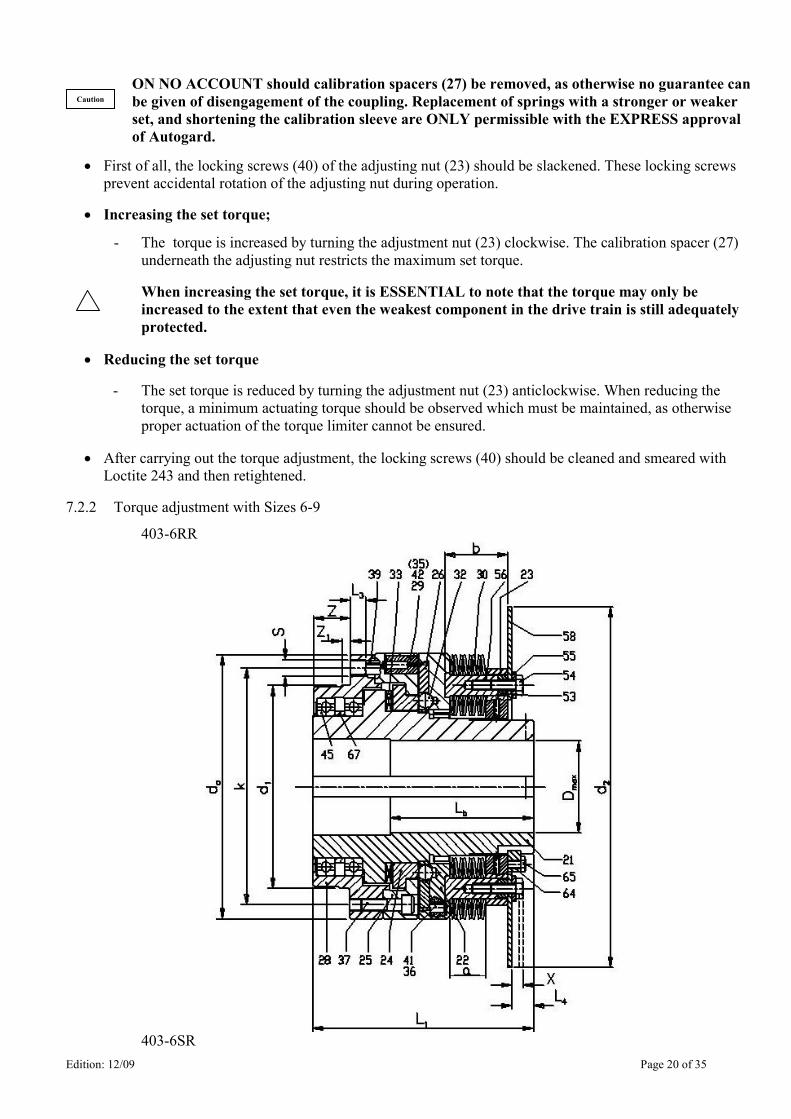
7.2.2 Torque adjustment with Sizes 6-9
403-6RR
403-6SR
Caution
Edition: 12/09 Page 21 of 35
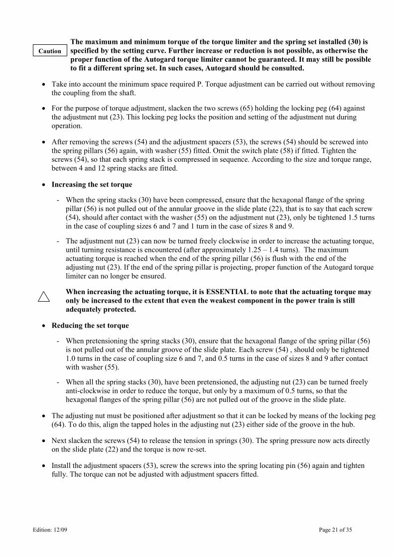
The maximum and minimum torque of the torque limiter and the spring set installed (30) is
specified by the setting curve. Further increase or reduction is not possible, as otherwise the
proper function of the Autogard torque limiter cannot be guaranteed. It may still be possible
to fit a different spring set. In such cases, Autogard should be consulted.
• Take into account the minimum space required P. Torque adjustment can be carried out without removing
the coupling from the shaft.
• For the purpose of torque adjustment, slacken the two screws (65) holding the locking peg (64) against
the adjustment nut (23). This locking peg locks the position and setting of the adjustment nut during
operation.
• After removing the screws (54) and the adjustment spacers (53), the screws (54) should be screwed into
the spring pillars (56) again, with washer (55) fitted. Omit the switch plate (58) if fitted. Tighten the
screws (54), so that each spring stack is compressed in sequence. According to the size and torque range,
between 4 and 12 spring stacks are fitted.
• Increasing the set torque
- When the spring stacks (30) have been compressed, ensure that the hexagonal flange of the spring
pillar (56) is not pulled out of the annular groove in the slide plate (22), that is to say that each screw
(54), should after contact with the washer (55) on the adjustment nut (23), only be tightened 1.5 turns
in the case of coupling sizes 6 and 7 and 1 turn in the case of sizes 8 and 9.
- The adjustment nut (23) can now be turned freely clockwise in order to increase the actuating torque,
until turning resistance is encountered (after approximately 1.25 – 1.4 turns). The maximum
actuating torque is reached when the end of the spring pillar (56) is flush with the end of the
adjusting nut (23). If the end of the spring pillar is projecting, proper function of the Autogard torque
limiter can no longer be ensured.
When increasing the actuating torque, it is ESSENTIAL to note that the actuating torque may
only be increased to the extent that even the weakest component in the power train is still
adequately protected.
• Reducing the set torque
- When pretensioning the spring stacks (30), ensure that the hexagonal flange of the spring pillar (56)
is not pulled out of the annular groove of the slide plate. Each screw (54) , should only be tightened
1.0 turns in the case of coupling size 6 and 7, and 0.5 turns in the case of sizes 8 and 9 after contact
with washer (55).
- When all the spring stacks (30), have been pretensioned, the adjusting nut (23) can be turned freely
anti-clockwise in order to reduce the torque, but only by a maximum of 0.5 turns, so that the
hexagonal flanges of the spring pillar (56) are not pulled out of the groove in the slide plate.
• The adjusting nut must be positioned after adjustment so that it can be locked by means of the locking peg
(64). To do this, align the tapped holes in the adjusting nut (23) either side of the groove in the hub.
• Next slacken the screws (54) to release the tension in springs (30). The spring pressure now acts directly
on the slide plate (22) and the torque is now re-set.
• Install the adjustment spacers (53), screw the screws into the spring locating pin (56) again and tighten
fully. The torque can not be adjusted with adjustment spacers fitted.
Caution
Edition: 12/09 Page 22 of 35
When the adjustment spacer (53) is fitted, a small gap must always be present between the
washer (53) and the adjusting nut (23).
• By means of a test run check whether the system can be operated as required. If further torque adjustment is
necessary, the adjustment procedure should be repeated.
• When adjustment is complete, the adjustment nut (23) should be locked in the required position again by means
of the locking peg (64). The screws (65) should be cleaned, smeared with Loctite 243 and fully re-tightened.
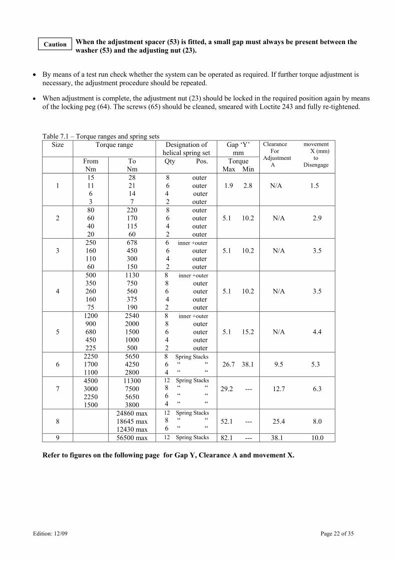
Table 7.1 – Torque ranges and spring sets
Size Torque range Designation of
helical spring set
Gap ‘Y’
mm
From
Nm
To
Nm
Qty Pos. Torque
Max Min
Clearance movement
For X (mm)
Adjustment to
A Disengage
1
15
11
6
3
28
21
14
7
8 outer
6 outer
4 outer
2 outer
1.9 2.8
N/A 1.5
2
80
60
40
20
220
170
115
60
8 outer
6 outer
4 outer
2 outer
5.1 10.2
N/A 2.9
3
250
160
110
60
678
450
300
150
6 inner +outer
6 outer
4 outer
2 outer
5.1 10.2
N/A 3.5
4
500
350
260
160
75
1130
750
560
375
190
8 inner +outer
8 outer
6 outer
4 outer
2 outer
5.1 10.2
N/A 3.5
5
1200
900
680
450
225
2540
2000
1500
1000
500
8 inner +outer
8 outer
6 outer
4 outer
2 outer
5.1 15.2
N/A 4.4
6
2250
1700
1100
5650
4250
2800
8 Spring Stacks
6 “ “
4 “ “
26.7 38.1
9.5 5.3
7
4500
3000
2250
1500
11300
7500
5650
3800
12 Spring Stacks
8 “ “
6 “ “
4 “ “
29.2 ---
12.7 6.3
8
24860 max
18645 max
12430 max
12 Spring Stacks
8 “ “
6 “ “
52.1 ---
25.4 8.0
9 56500 max 12 Spring Stacks 82.1 --- 38.1 10.0
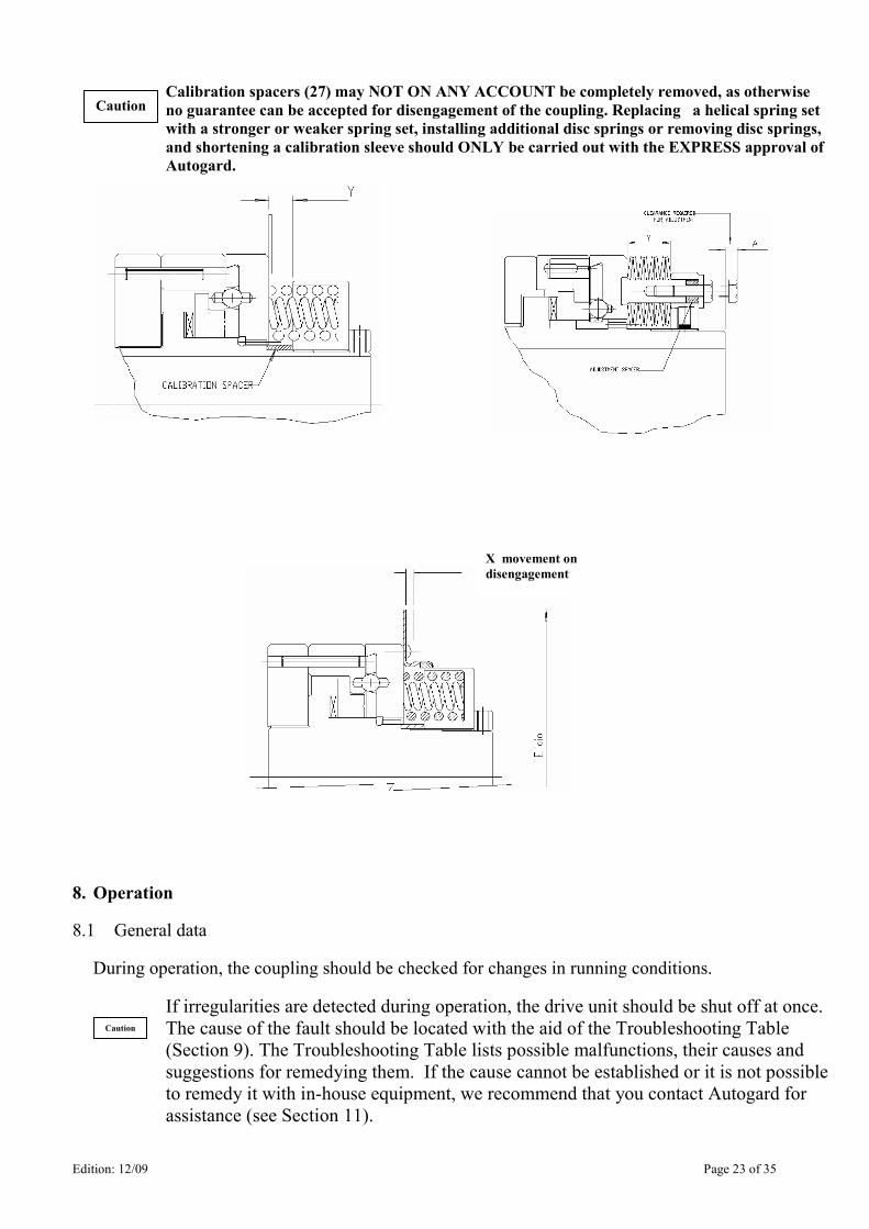
Refer to figures on the following page for Gap Y, Clearance A and movement X.
Caution
Edition: 12/09 Page 23 of 35
X movement on
disengagement
Calibration spacers (27) may NOT ON ANY ACCOUNT be completely removed, as otherwise
no guarantee can be accepted for disengagement of the coupling. Replacing a helical spring set
with a stronger or weaker spring set, installing additional disc springs or removing disc springs,
and shortening a calibration sleeve should ONLY be carried out with the EXPRESS approval of
Autogard.
8. Operation
8.1 General data
During operation, the coupling should be checked for changes in running conditions.
If irregularities are detected during operation, the drive unit should be shut off at once.
The cause of the fault should be located with the aid of the Troubleshooting Table
(Section 9). The Troubleshooting Table lists possible malfunctions, their causes and
suggestions for remedying them. If the cause cannot be established or it is not possible
to remedy it with in-house equipment, we recommend that you contact Autogard for
assistance (see Section 11).
Caution
Caution
Edition: 12/09 Page 24 of 35
9. Troubleshooting
9.1 General
The items listed below can only serve as a guide to troubleshooting, in relation to the torque limiter. With a
complex system, all other components must also be included in any investigation. In particular, if there are
unusual noises, other equipment should be examined even if the sound seems to be coming from the torque
limiter. Our experience is that such noises can be emitted from the torque limiter even though it is not the
source of the problem.
9.2 Normal Operation
The torque limiter should run silently and without vibration in normal operation.
In the event of an overload, the torque limiter will disengage when the set torque is exceeded. During
disengagement, a sharp snapping action may be heard which occurs when the spring load transfers from the
outer drive balls (32) to the inner strut balls. When running disengaged, a clicking noise will be heard which
is caused by the pawls (29) running on the slide / cage plate assembly (22/26). On resetting, a noise will be
heard as the balls (32) re-engage in their seats.
Any other behaviour should be investigated and remedied at once to avoid damage to the torque limiter and
other equipment.
Frequent disengagements of the Autogard torque limiter should be investigated, as
otherwise premature wear may occur.
Before carrying out maintenance, repairs or other work, the operator has to ensure that the
entire drive train is stationary. In particular, the drive motors should be secured to prevent
accidental startup. In addition, we would draw attention to the Health and Safety
Regulations applicable on site.
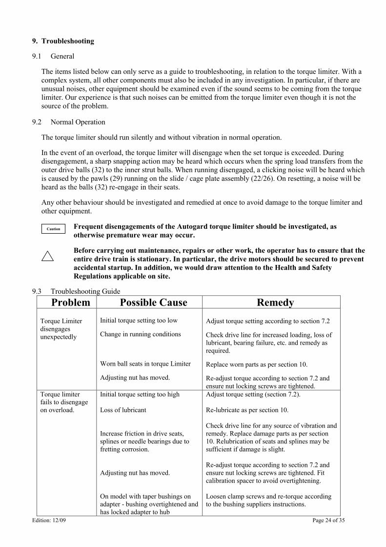
9.3 Troubleshooting Guide
Problem Possible Cause Remedy Torque Limiter
disengages
unexpectedly
Initial torque setting too low
Change in running conditions
Worn ball seats in torque Limiter
Adjusting nut has moved.
Adjust torque setting according to section 7.2
Check drive line for increased loading, loss of
lubricant, bearing failure, etc. and remedy as
required.
Replace worn parts as per section 10.
Re-adjust torque according to section 7.2 and
ensure nut locking screws are tightened.
Torque limiter
fails to disengage
on overload.
Initial torque setting too high
Loss of lubricant
Increase friction in drive seats,
splines or needle bearings due to
fretting corrosion.
Adjusting nut has moved.
On model with taper bushings on
adapter - bushing overtightened and
has locked adapter to hub
Adjust torque setting (section 7.2).
Re-lubricate as per section 10.
Check drive line for any source of vibration and
remedy. Replace damage parts as per section
10. Relubrication of seats and splines may be
sufficient if damage is slight.
Re-adjust torque according to section 7.2 and
ensure nut locking screws are tightened. Fit
calibration spacer to avoid overtightening.
Loosen clamp screws and re-torque according
to the bushing suppliers instructions.
Caution
Edition: 12/09 Page 25 of 35
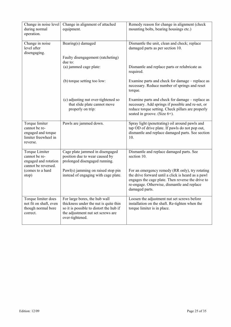
Change in noise level
during normal
operation.
Change in alignment of attached
equipment.
Remedy reason for change in alignment (check
mounting bolts, bearing housings etc.)
Change in noise
level after
disengaging.
Bearing(s) damaged
Faulty disengagement (ratcheting)
due to:
(a) jammed cage plate:
(b) torque setting too low:
(c) adjusting nut over-tightened so that slide plate cannot move
properly on trip:
Dismantle the unit, clean and check; replace
damaged parts as per section 10.
Dismantle and replace parts or relubricate as
required.
Examine parts and check for damage – replace as
necessary. Reduce number of springs and reset
torque.
Examine parts and check for damage – replace as
necessary. Add springs if possible and re-set, or
reduce torque setting. Check pillars are properly
seated in groove. (Size 6+).
Torque limiter
cannot be re-
engaged and torque
limiter freewheel in
reverse.
Pawls are jammed down. Spray light (penetrating) oil around pawls and
tap OD of drive plate. If pawls do not pop out,
dismantle and replace damaged parts. See section
10.
Torque Limiter
cannot be re-
engaged and rotation
cannot be reversed.
(comes to a hard
stop)
Cage plate jammed in disengaged
position due to wear caused by
prolonged disengaged running.
Pawl(s) jamming on raised stop pin
instead of engaging with cage plate.
Dismantle and replace damaged parts. See
section 10.
For an emergency remedy (RR only), try rotating
the drive forward until a click is heard as a pawl
engages the cage plate. Then reverse the drive to
re-engage. Otherwise, dismantle and replace
damaged parts.
Torque limiter does
not fit on shaft, even
though normal bore
correct.
For large bores, the hub wall
thickness under the nut is quite thin
so it is possible to distort the hub if
the adjustment nut set screws are
over-tightened.
Loosen the adjustment nut set screws before
installation on the shaft. Re-tighten when the
torque limiter is in place.
Edition: 12/09 Page 26 of 35
10. Maintenance and servicing
10.1 General
Maintenance and servicing may ONLY be carried out by trained personnel.
If suitable specialist personnel are not available, the torque limiter may be returned to Autogard to ensure
proper workmanship.
Autogard torque limiters can be used as standard in ambient temperatures of –30 C to +80 C. Outside this
temperature range, special greases and oils should be used. Please consult Autogard.
Dependent upon environment and number of trips, the torque limiter should be inspected and serviced
every 2000 hrs. Under adverse conditions in dirty environments and with frequent trips a shorter service
interval is recommended. In any event, when a machine is subjected to a major overhaul, the Autogard
torque limiter should be checked at the same time.
The journal bearings used are of high-grade P.T.F.E. or oil-impregnated bronze and are maintenance-free.
Ball bearings are sealed for life.
It should be checked that all components are firmly attached to one another and that all components locate
firmly on the coupling hub. For the purpose of checking the lubrication, the adjuster nut (23) and the slide
plate (22) should be removed from the torque limiter. To do this, or any other service operation, it will
normally be necessary to remove the complete torque limiter from the shaft.
Lubricants described under section 10.6 or equivalent should be used.
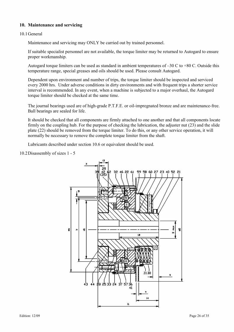
10.2 Disassembly of sizes 1 - 5
Edition: 12/09 Page 27 of 35
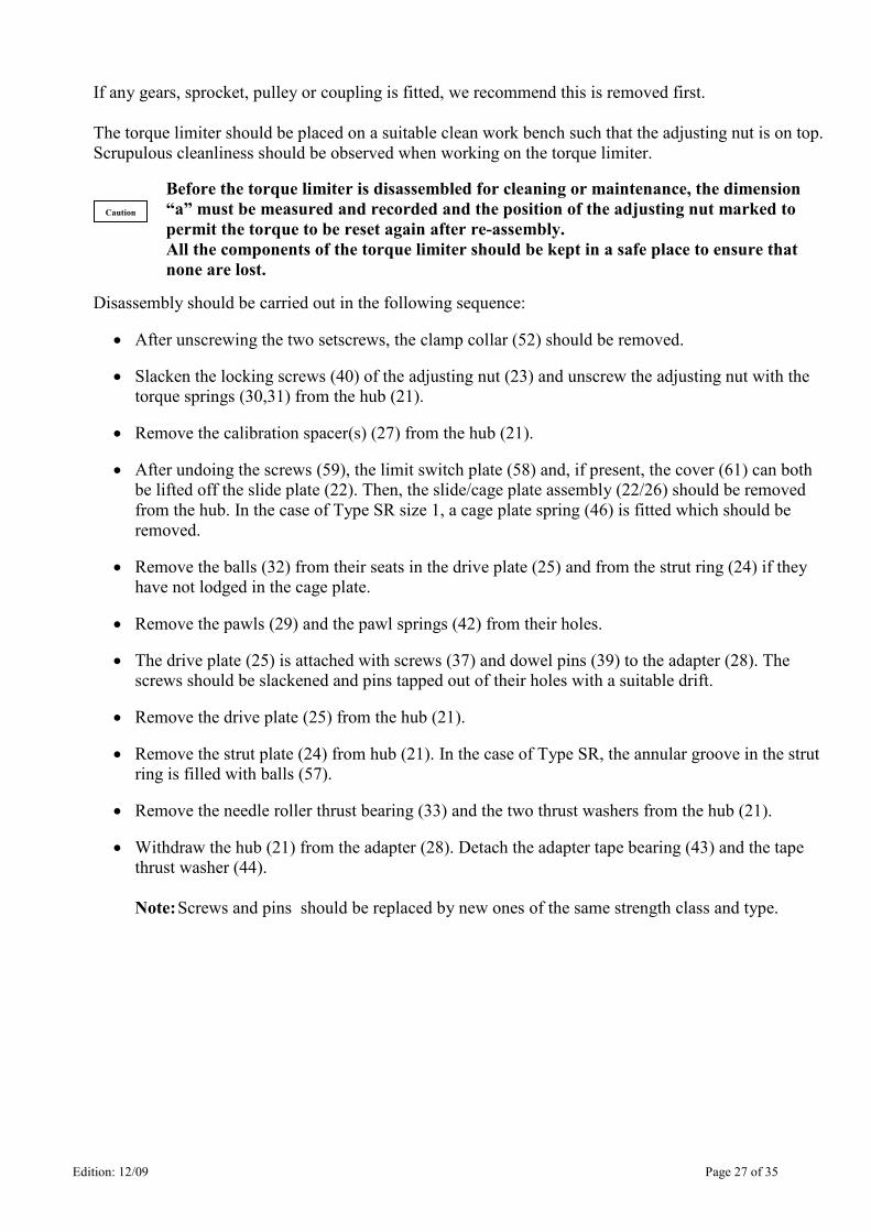
If any gears, sprocket, pulley or coupling is fitted, we recommend this is removed first.
The torque limiter should be placed on a suitable clean work bench such that the adjusting nut is on top.
Scrupulous cleanliness should be observed when working on the torque limiter.
Before the torque limiter is disassembled for cleaning or maintenance, the dimension
“a” must be measured and recorded and the position of the adjusting nut marked to
permit the torque to be reset again after re-assembly.
All the components of the torque limiter should be kept in a safe place to ensure that
none are lost.
Disassembly should be carried out in the following sequence:
• After unscrewing the two setscrews, the clamp collar (52) should be removed.
• Slacken the locking screws (40) of the adjusting nut (23) and unscrew the adjusting nut with the
torque springs (30,31) from the hub (21).
• Remove the calibration spacer(s) (27) from the hub (21).
• After undoing the screws (59), the limit switch plate (58) and, if present, the cover (61) can both
be lifted off the slide plate (22). Then, the slide/cage plate assembly (22/26) should be removed
from the hub. In the case of Type SR size 1, a cage plate spring (46) is fitted which should be
removed.
• Remove the balls (32) from their seats in the drive plate (25) and from the strut ring (24) if they
have not lodged in the cage plate.
• Remove the pawls (29) and the pawl springs (42) from their holes.
• The drive plate (25) is attached with screws (37) and dowel pins (39) to the adapter (28). The
screws should be slackened and pins tapped out of their holes with a suitable drift.
• Remove the drive plate (25) from the hub (21).
• Remove the strut plate (24) from hub (21). In the case of Type SR, the annular groove in the strut
ring is filled with balls (57).
• Remove the needle roller thrust bearing (33) and the two thrust washers from the hub (21).
• Withdraw the hub (21) from the adapter (28). Detach the adapter tape bearing (43) and the tape
thrust washer (44).
Note: Screws and pins should be replaced by new ones of the same strength class and type.
Caution
Edition: 12/09 Page 28 of 35
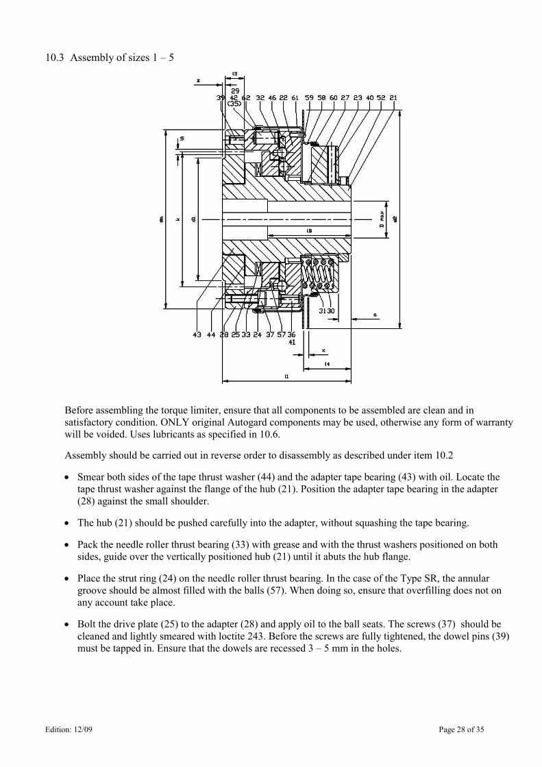
10.3 Assembly of sizes 1 – 5
Before assembling the torque limiter, ensure that all components to be assembled are clean and in
satisfactory condition. ONLY original Autogard components may be used, otherwise any form of warranty
will be voided. Uses lubricants as specified in 10.6.
Assembly should be carried out in reverse order to disassembly as described under item 10.2
• Smear both sides of the tape thrust washer (44) and the adapter tape bearing (43) with oil. Locate the
tape thrust washer against the flange of the hub (21). Position the adapter tape bearing in the adapter
(28) against the small shoulder.
• The hub (21) should be pushed carefully into the adapter, without squashing the tape bearing.
• Pack the needle roller thrust bearing (33) with grease and with the thrust washers positioned on both
sides, guide over the vertically positioned hub (21) until it abuts the hub flange.
• Place the strut ring (24) on the needle roller thrust bearing. In the case of the Type SR, the annular
groove should be almost filled with the balls (57). When doing so, ensure that overfilling does not on
any account take place.
• Bolt the drive plate (25) to the adapter (28) and apply oil to the ball seats. The screws (37) should be
cleaned and lightly smeared with loctite 243. Before the screws are fully tightened, the dowel pins (39)
must be tapped in. Ensure that the dowels are recessed 3 – 5 mm in the holes.
Edition: 12/09 Page 29 of 35
The drive plate (25) must rotate freely on the hub (21). In the same way, the strut
ring (24) must rotate freely between drive plate and hub.
The dowel pins (39) must NOT protrude through the drive plate!
• For pawls with counterbores, the pawl springs (42) should be greased and inserted in the pawls (29). The
pawls and the pawl springs should then be inserted in the holes of the drive plate (25). Type SR pawls are
secured by means of a roll pin (35), thus preventing incorrect assembly. When this pin is fitted, ensure that
the seam of the pin faces away from the pawl. After assembly, check that the pawls can move freely in the
holes. They should extend freely under spring pressure alone.
• A calibration spacer (27) suitable for the actuating torque should be placed over the hub and rest against the
spline.
Calibration spacers (27) may NOT ON ANY ACCOUNT be completely removed, as
otherwise no guarantee can be accepted for disengagement of the coupling. Replacing a
helical spring set with a stronger or weaker spring set, installing or removing disc springs,
and shortening a calibration sleeve are ONLY permissible with the EXPRESS approval of
Autogard.
If the cage plate (26) has been removed from the slide plate (22), it should be refitted as follows. Apart from
size 1 type SR, a bayonet design is used for cage plate retention. There are cutouts to facilitate initial insertion
of the cage plate, which is then rotated to engage the bayonet features. For type SR, the cage plate is initially
inserted at 90° to its final position and for type RR it is inserted at 180° to its final position.
The correct angular position of the cage plate (26) relative to the slide plate (22) is most
important. All the inner and outer ball seats should be visible through the cage plate holes
and the ramped recess(es) in the slide plate must be aligned with cut-out(s) in the cage plate.
On SR units, it is the straight edged cut-out which is aligned with the ramps. With the cage
plate in this position, the stop pins will be centrally positioned in the correct cutout(s) in the
cage plate.
Lightly smear the faces of the plates with oil, including ball seats. Fit the cage plate and rotate to the correct
position as above. The stop pins (36,41) should now be inserted. On all but size 1, an inner and an outer pin is
used. The split line on the outer pin must face outwards. The inner pin is inserted so that its split line is
opposite the split line in the outer. Check that the cage plate can rotate freely between the stop pins.
In the case of size 1, type SR, the cage plate is retained by cage plate spring (46) which should be fitted over the
hub and resting on the strut ring (24). The cage plate must be fitted with the turned location groove for the cage
plate spring being visible. Oil the faces as above and insert in the correct position as previously described, i.e.
straight edged cut-out aligned with the ramps on the slide plate (22). Fit the single stop pin with its split line
facing outwards.
• Whatever the model, assembly can now proceed as follows. The balls (32) should then be inserted in the
lightly greased holes. The grease facilitates assembly on the hub (21). The hub splines should be smeared
with the correct grease before assembly (See 10.6). After inserting the slide plate onto the splines, the hub
should be held in position and the drive plate turned until the balls engage in their seats.
The slide plate must be held down against the pawl springs while the adjusting nut (with the torque springs)
is screwed on.
• The torque springs (30, 31) should be inserted into the adjusting nut with grease to hold them in place.
Ensure that the springs are uniformly distributed. Before the adjusting nut is screwed onto the hub (21), the
threads on both components should be smeared with grease.
Caution
Caution
Caution
Edition: 12/09 Page 30 of 35
• The switch plate (58) and, if fitted, the cover (61) should be bolted onto the slide plate with the screws (59).
After cleaning, the screws should be smeared with Loctite 243 and fully tightened. During assembly of the
cover (61) and the switch plate (58), ensure that if felt strips (60, 62) are inserted, they are not crushed. New
felt strips should be soaked in oil before assembly of the cover.
• If the coupling is being reassembled after a service, ensure that the adjusting nut (23) is positioned exactly as
before disassembly, in order to ensure the same actuating torque (see item 10.2: Disassembly). The
adjusting nut (23) should now be locked in position by tightening the locking screws (40). The locking
screws should be cleaned, smeared with Loctite 243 and fully tightened. Note: do not overtighten as this may
crush the bore of the hub.
• The clamp collar (52) should be placed on the hub (21) and the setscrews inserted. When assembling the
torque limiter on the shaft, the hub should be located on the shaft with these setscrews.
• Before re-installing on the shaft, any gear, sprocket, pulley or coupling should be re-fitted.
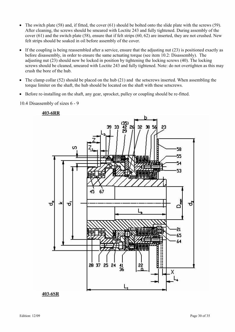
10.4 Disassembly of sizes 6 - 9
403-6RR
403-6SR
Edition: 12/09 Page 31 of 35
Before starting the disassembly, it is recommended that any gears, sprocket, pulley or coupling fitted to the
torque limiter is removed.
The torque limiter should be placed on a suitable clean bench such that the adjusting nut is on top.
Scrupulous cleanliness should be observed when working on the torque limiter.
Before the torque limiter is disassembled for cleaning or maintenance, the dimension
“a” must be measured and recorded and the position of the adjusting nut marked to
permit setting exactly the same actuating torque again after assembly.
All the components of the torque limiter should be kept in a safe place to ensure that
none is lost.
Disassembly should be carried out in the following sequence:
• First of all, unscrew the two screws (65) and remove the locking peg (64).
• After slackening and unscrewing the screws (54) remove the switch plate (58) (if fitted) and the
adjustment spacers (53). The screws (54) together with the washer (55) should be screwed back into
the spring pillars (56). Each spring stack should now be pretensioned in sequence by tightening the
screws (54). According to size and actuating torque range, between 4 and 12 springs stacks may be
fitted. See Section 7.
• When pretensioning the spring stacks (30) ensure that the hexagonal flange of the spring pillar (56) is
not pulled out of the annular groove in the slide plate (22). Each screw (54) should be tightened 1.5
turns in the case of coupling Sizes 6 and 7, and 1 turn in the case of Size 8 and 9.
• Unscrew the adjusting nut (23) together with the spring stacks (30) from hub (21). By slackening the
screws (54) again, the spring stacks can, if necessary, be disassembled from the adjusting nut. In this
case, it is ESSENTIAL to measure dimension “b” beforehand.
• Remove the slide / cage plate assembly (22/26) from the hub.
• Remove the balls (32) from their seats in the drive plate (25) and from the strut ring (24) if they have
not lodged in the cage plate.
• Remove the pawls (29) with the pawl springs (42) from their holes.
• The drive plate (25) is attached with screws (37) and dowel pins (39) to the adapter (28). The screws
should be slackened and pins tapped out of their holes with a suitable drift.
• Remove the drive plate (25) from the hub (21).
• Remove the strut ring (24) from the hub (21).
• Remove the needle roller thrust bearing (33) with the two thrust washers from hub (21).
• Withdraw the hub (21) from the adapter (28); pull the two ball bearings (45) and the spacer (67) off the
hub and out of the adapter. When disassembling the ball bearings the manufacturer’s instructions
should be followed.
Caution
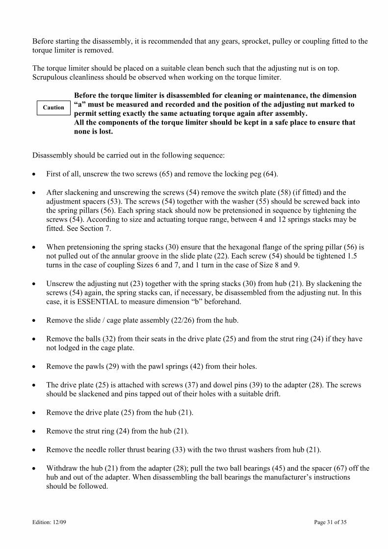
Edition: 12/09 Page 32 of 35
10.5 Assembly of sizes 6 - 9
403-6RR
403-6SR
Before assembling the torque limiter, ensure that all components to be assembled are clean and in
satisfactory condition. ONLY original Autogard components may be used, otherwise any form of warranty
will be void.
Assembly should be carried out in reverse order to disassembly as described under Item 10.4.
• Assemble the two ball bearings (45) and the spacer (67) on the hub (21) and into the adapter (28),
observing the bearing manufacturer’s instructions.
• Pack the needle roller thrust bearing (33) with grease and , with the thrust washers placed on both
sides, guide over the hub (21) while it is positioned upright.
• Place the strut ring (24) on the needle roller thrust bearing.
• Bolt the drive plate (25) to the adapter (28) and apply oil to the ball seats. The screws (37) used for this
purpose should be cleaned and lightly smeared with Loctite 243. Before the screws are fully tightened,
the dowel pins (39) must be tapped in. When doing so, ensure that the dowels are recessed 3-5 mm in
the holes.
Edition: 12/09 Page 33 of 35
The drive plate (25) must rotate freely on the hub (21). In the same way, the strut ring
(24) must rotate freely between drive plate and hub.
The dowel pins (29) must NOT stand proud of the drive plate!
• The pawl springs (42) should be inserted with grease in the pawls (29) and should then be inserted in
the holes of the drive plate (25). Type SR pawls are secured by means of a dowel pin (35), thus
preventing incorrect assembly. When this dowel pin is fitted, ensure that the seam of the pin faces
away from the pawl. After assembly, check that the pawls can move freely in their holes. They should
extend under spring pressure alone.
• If the cage plate (26) has been removed from the slide plate (22), it should be refitted as follows. A
bayonet design is used for cage plate retention. There are cutouts to facilitate initial insertion of the
cage plate, which is then rotated to engage the bayonet features. For type SR, the cage plate is initially
inserted at 90° to its final position and for type RR it is inserted at 180° to its final position.
The correct angular position of the cage plate (26) relative to the slide plate (22) is most
important. Ball seats in the slide plate should be visible through all the cage plate holes
(inner and outer) and the ramped recess(es) in the slide plate must be aligned with cut-
out(s) in the cage plate. On SR units, it is the straight edged cut-out which is aligned
with the ramps. With the cage plate in this position, the stop pins will be centrally
positioned in the correct cutout(s) in the cage plate.
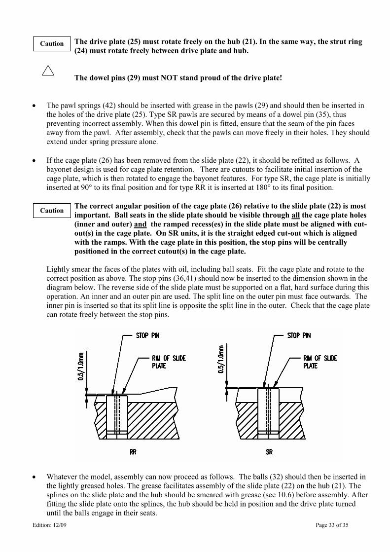
Lightly smear the faces of the plates with oil, including ball seats. Fit the cage plate and rotate to the
correct position as above. The stop pins (36,41) should now be inserted to the dimension shown in the
diagram below. The reverse side of the slide plate must be supported on a flat, hard surface during this
operation. An inner and an outer pin are used. The split line on the outer pin must face outwards. The
inner pin is inserted so that its split line is opposite the split line in the outer. Check that the cage plate
can rotate freely between the stop pins.
• Whatever the model, assembly can now proceed as follows. The balls (32) should then be inserted in
the lightly greased holes. The grease facilitates assembly of the slide plate (22) on the hub (21). The
splines on the slide plate and the hub should be smeared with grease (see 10.6) before assembly. After
fitting the slide plate onto the splines, the hub should be held in position and the drive plate turned
until the balls engage in their seats.
Caution
Caution
Edition: 12/09 Page 34 of 35
• If the spring stacks (30) have previously been disassembled, they should be placed in their previous
arrangement on the spring pillars (56) and assembled with screws (54), using washers (55), on the
adjusting nut (23). When retensioning the individual spring stacks, it is ESSENTIAL to maintain the
previously measured dimension ‘b’. In addition, ensure symmetrical distribution of the spring stacks.
• Smear the thread of the adjusting nut (23) and the hub (21) with grease and screw the adjusting nut
onto the hub. Ensure that the hexagonal flange of each spring pillar (56) is located in the annular
groove in the slide plate.
• The adjustment spacers (53) should be re-fitted and the switch plate (58) repositioned (if present). The
screws (54) should be cleaned, smeared with Loctite 243 and fully tightened.
• If the coupling is being reassembled after a service, ensure that the adjusting nut (23) is positioned
exactly as before disassembly, in order to maintain the original actuating torque (see Item 10.4:
Disassembly). The adjusting nut (23) should now be secured to prevent rotation by fitting the locking
peg (64). The screws (65) should be cleaned, smeared with Loctite 243 and fully tightened.
• Any gears, sprocket, pulley or coupling can now be refitted to the torque limiter.
10.6 Lubricants
For general purpose application, use Shell Alania R3, BP Energrease LS3 or any good quality Lithium
grease NLGI #3. Power-up Thixogrease (NLGI #2) may also be used.
For splines use Rocol Sapphire Hi-Pressure (Formerly MTS1000) or equivalent.
For oiling PTFE bearings and ball seats, use Mobil Vactra No. 2 or equivalent.
11. Stocking spare parts, Customer facility addresses
A stock of the most essential spare and wearing parts on site is an important precondition for serviceability
of the torque limiter at all times.
Please refer to table 1.1 shown on page 3 for ordering spare parts. For full details of part numbers and
quantities, please consult Autogard.
Additional information including general arrangement drawings and full parts lists will be found at our
website www.autogard.com.
Our warranty only covers original spare parts supplied by Autogard.
We would expressly point out that spare parts and accessories not supplied by Autogard
have not been tested and approved. Installation and/or use of such products can under
certain circumstances adversely affect the specified structural properties of the torque
limiter and thus impair its active and/or passive safety. No form of liability or warranty is
accepted on the part of Autogard for damage which occurs as a result of the use of non-
original spare parts and accessories.
Please note that special manufacturing and supply specifications frequently exist for components and that
we always supply spare parts in accordance with the state of the art and in accordance with the latest legal
requirements.
Caution
Edition: 12/09 Page 35 of 35
When ordering spare parts, the following data should be stated:
Order No. Part Quantity
11.1 Addresses of spare parts stockists and service facilities
British Autogard Ltd American Autogard Corporation
Cirencester 5173 26th Avenue
Glos, GL7 1YT Rockford, IL 61109
England U.S.A.
Tel: +44 (0)1285 640333 Tel: +1 815 633 1441
Fax: +44 (0) 1285 659476 Fax: +1 815 633 8488
Email: [email protected] Email: [email protected]
Autogard Kupplungen GmbH Autogard Italia S.r.l
Im Wied 2 Via Udine 3,
32683 Barntrup 20063 Cernusco sul Naviglio, Milano
Germany Italy
Tel: +49 (0)5263 9549 60 Tel: +39 (0)291 700471
Fax: +49 (0)5263 9549 69 Fax: +39 (0)291 700472
Email: [email protected] Email: [email protected]
Autogard Asia-Pacific Pty Ltd Autogard Japan Ltd
Unit 17, 56 Keys Road 15-16, 2- Chome, Takanawa
Cheltenham, Victoria 3192 Minato-Ku, Tokyo 108
Australia Japan
Tel: +61 (0) 39532 0901 Tel: +81 3 34499621
Fax: +61 (0) 39532 1032 Fax: +81 3 54497491
Email: [email protected] Email: [email protected]


![I N D E X [] · I N D E X Part-Number Page Part-Number Page Part-Number Page](https://img.pdfslide.us/doc/110x75/5e14b45cbc58224d7c1c75a6/i-n-d-e-x-i-n-d-e-x-part-number-page-part-number-page-part-number-page.jpg)