Embed Size (px)
Citation preview
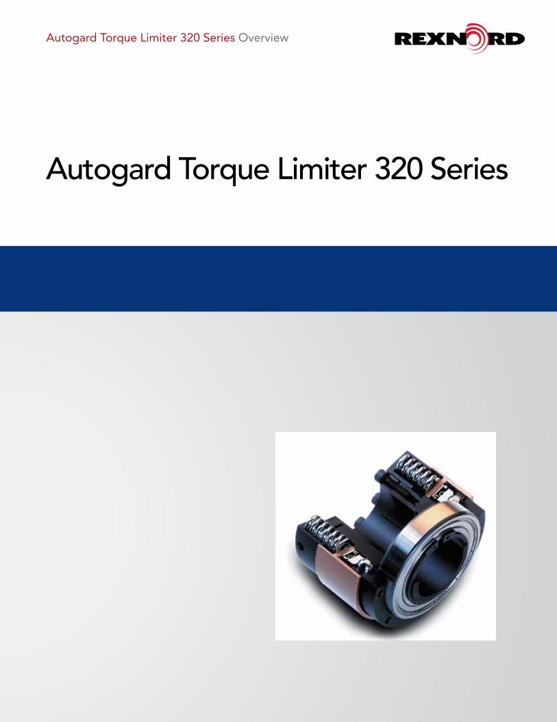
Autogard Torque Limiter 320 Series Overview
Autogard Torque Limiter 320 Series
Torque Limiter 320 Series For more than 80 years, Autogard® products have led the industry in overload protection with high-quality products, design innovation and production. Autogard products are manufactured to meet ISO 9001 using the latest machine tools and high-quality materials.
Acting like a mechanical “fuse” to protect the weakest member of the drive train, the most effective location for Autogard Torque Limiters is as close as possible to the component being protected. The 320 Series has been designed to meet the need for a compact and reliable safety clutch. The optimized design provides a robust, backlash-free clutch that will protect equipment from the damaging effects caused by overloading a drive train. The SR Reset features a timed automatic re-engagement as a standard.
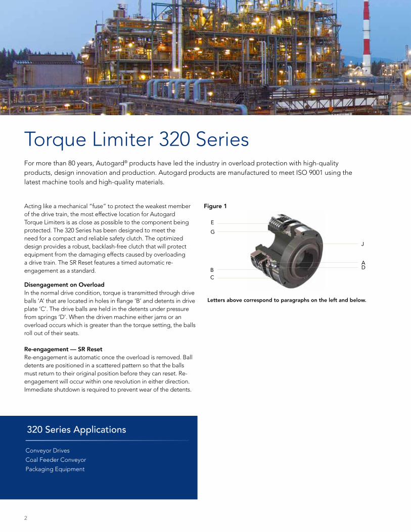
Disengagement on OverloadIn the normal drive condition, torque is transmitted through drive balls ‘A’ that are located in holes in flange ‘B’ and detents in drive plate ‘C’. The drive balls are held in the detents under pressure from springs ‘D’. When the driven machine either jams or an overload occurs which is greater than the torque setting, the balls roll out of their seats.
Re-engagement — SR ResetRe-engagement is automatic once the overload is removed. Ball detents are positioned in a scattered pattern so that the balls must return to their original position before they can reset. Re-engagement will occur within one revolution in either direction. Immediate shutdown is required to prevent wear of the detents.
Figure 1
320 Series Applications
Conveyor Drives
Coal Feeder Conveyor
Packaging Equipment
J
G
Letters above correspond to paragraphs on the left and below.
E
BC
AD
2
Features and Benefits: • Accurate torque limitation prevents costly downtime
caused by overloads
• Compact design reduces weight and inertia on the equipment
• Bi-directional operation
• The standard design can accommodate larger torque ranges than many other models currently available
• Backlash-free operation
• One revolution synchronous re-engagement as standard
• Springs can be inspected and changed without removing the clutch from the drive train
• Coil springs allow one standard design to accommodate the full torque range as opposed to regressive disc springs that can only accommodate a narrow torque band
• Bore options with conventional bore and key or cone clamp sleeve for keyless connection
Selection: Data required for torque limiter selection:
• Application details for service factors
• Kilowatt (kW) and rpm of the driver
• Shaft details of the driving and driven equipment
(1) Calculate the nominal torque.
Example: 320-2 / 2 / SR / 35Refers to a 320 Series, Size 2, Type 2 torque limiter designed for Single Position Reset S2 Bore = 35 mmAlso specify setting torque and/or pulley or sprocket if required.
The specifications contained within this brochure are correct at the time of going to print. Rexnord is continually reviewing and updating the specifications on its entire Autogard product offering and therefore reserve the right to change any detail.
Ordering the 320 Series Torque Limiter When ordering, please provide the following designation: Model and Size / Type / Reset / S1 Standard bore tolerance = H7 + normal fit key
Torque (Nm) = Kw x 9550 / rpm
Consideration should then be given to start torque or other special circumstances depending on the position chosen in the drive system. Choose a set torque with a suitable margin over nominal. Select the torque limiter which has a higher torque rating.
(2) Check limiting conditions: (a) Check running speed(b) Check hub bore capacity(c) Check the torque limiter dimensions such
as the overall length and outside diameter
(3) Select and specify the appropriate drive medium.
All 320 Series units may be supplied from the factory at a pre-set torque and with the required drive medium assembled to the unit.
3
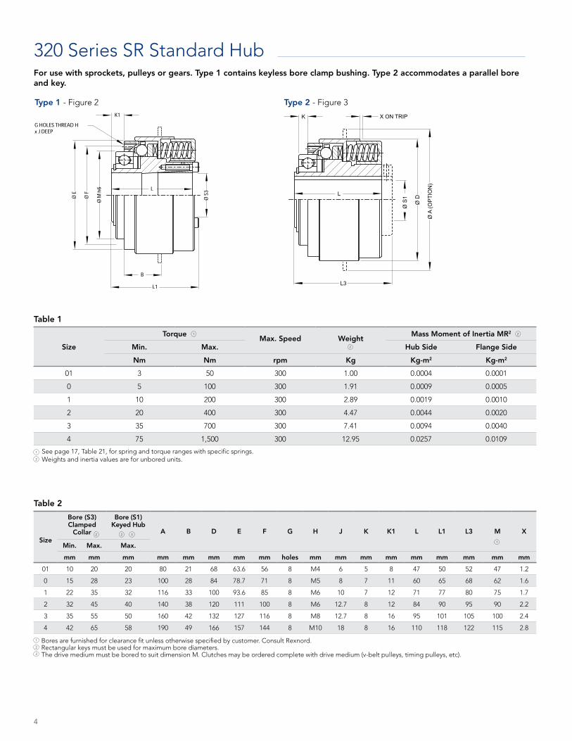
320 Series SR Standard Hub
Size
TorqueMax. Speed Weight
Mass Moment of Inertia MR2
Min. Max. Hub Side Flange Side
Nm Nm rpm Kg Kg-m2 Kg-m2
01 3 50 300 1.00 0.0004 0.0001
0 5 100 300 1.91 0.0009 0.0005
1 10 200 300 2.89 0.0019 0.0010
2 20 400 300 4.47 0.0044 0.0020
3 35 700 300 7.41 0.0094 0.0040
4 75 1,500 300 12.95 0.0257 0.0109
Size
Bore (S3) Clamped
Collar
Bore (S1) Keyed Hub
A B D E F G H J K K1 L L1 L3 M X
Min. Max. Max.
mm mm mm mm mm mm mm mm holes mm mm mm mm mm mm mm mm mm
01 10 20 20 80 21 68 63.6 56 8 M4 6 5 8 47 50 52 47 1.2
0 15 28 23 100 28 84 78.7 71 8 M5 8 7 11 60 65 68 62 1.6
1 22 35 32 116 33 100 93.6 85 8 M6 10 7 12 71 77 80 75 1.7
2 32 45 40 140 38 120 111 100 8 M6 12.7 8 12 84 90 95 90 2.2
3 35 55 50 160 42 132 127 116 8 M8 12.7 8 16 95 101 105 100 2.4
4 42 65 58 190 49 166 157 144 8 M10 18 8 16 110 118 122 115 2.8
Table 1
See page 17, Table 21, for spring and torque ranges with specific springs. Weights and inertia values are for unbored units.
Table 2
Bores are furnished for clearance fit unless otherwise specified by customer. Consult Rexnord. Rectangular keys must be used for maximum bore diameters. The drive medium must be bored to suit dimension M. Clutches may be ordered complete with drive medium (v-belt pulleys, timing pulleys, etc).
K
L3
L
Ø S
1
Ø D
Ø A
(OP
TIO
N)
X ON TRIP
Type 1 - Figure 2 Type 2 - Figure 3
1
2
1
2
3
1 2
2
2 32
1
4
For use with sprockets, pulleys or gears. Type 1 contains keyless bore clamp bushing. Type 2 accommodates a parallel bore and key.
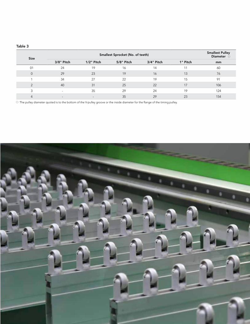
SizeSmallest Sprocket (No. of teeth)
Smallest PulleyDiameter
3/8" Pitch 1/2" Pitch 5/8" Pitch 3/4" Pitch 1" Pitch mm
01 24 19 16 14 11 60
0 29 23 19 16 13 76
1 34 27 22 19 15 91
2 40 31 25 22 17 106
3 - 35 29 24 19 124
4 - - 35 29 23 154
Table 3
The pulley diameter quoted is to the bottom of the V-pulley groove or the inside diameter for the flange of the timing pulley.
1
1
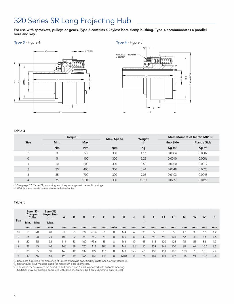
320 Series SR Long Projecting Hub
Size
TorqueMax. Speed Weight
Mass Moment of Inertia MR2
Min. Max. Hub Side Flange Side
Nm Nm rpm Kg Kg-m2 Kg-m2
01 3 50 300 1.16 0.0004 0.0002
0 5 100 300 2.28 0.0010 0.0006
1 10 200 300 3.50 0.0020 0.0012
2 20 400 300 5.64 0.0048 0.0025
3 35 700 300 9.05 0.0103 0.0048
4 75 1,500 300 15.83 0.0277 0.0129
Size
Bore (S3) Clamped
Collar
Bore (S1) Keyed Hub
A B D E F G H J K L L1 L3 M W W1 X
Min. Max. Max.
mm mm mm mm mm mm mm mm holes mm mm mm mm mm mm mm mm mm mm
01 10 20 20 80 21 68 63.6 56 8 M4 6 30 72 75 77 47 33 6.5 1.2
0 15 28 24 100 22 84 78.7 71 8 M5 8 40 93 97 101 62 43 8.5 1.6
1 22 35 32 116 33 100 93.6 85 8 M6 10 45 115 120 123 75 55 8.8 1.7
2 32 45 40 140 38 120 111 100 8 M6 12.7 55 139 145 150 90 67 10.6 2.2
3 35 55 50 160 42 132 127 116 8 M8 12.7 65 152 158 162 100 73 10.5 2.4
4 42 65 58 190 49 166 157 144 8 M10 18 75 185 193 197 115 91 10.5 2.8
Table 4
W1
G HOLES THREAD Hx J DEEP
B
L3
L
Ø S
1
Ø D
Ø A
(OP
TIO
N)
Type 3 - Figure 4 Type 4 - Figure 5
See page 17, Table 21, for spring and torque ranges with specific springs. Weights and inertia values are for unbored units.
Table 5
Bores are furnished for clearance fit unless otherwise specified by customer. Consult Rexnord. Rectangular keys must be used for maximum bore diameters. The drive medium must be bored to suit dimension K and supported with suitable bearing. Clutches may be ordered complete with drive medium (v-belt pulleys, timing pulleys, etc).
1
2
1
2
3
1 2
2
32
1
6
For use with sprockets, pulleys or gears. Type 3 contains a keyless bore clamp bushing. Type 4 accommodates a parallel bore and key.
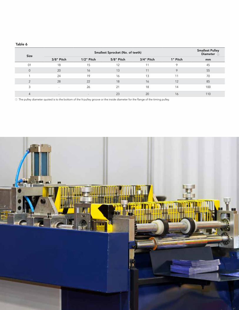
SizeSmallest Sprocket (No. of teeth)
Smallest PulleyDiameter
3/8" Pitch 1/2" Pitch 5/8" Pitch 3/4" Pitch 1" Pitch mm
01 18 15 12 11 9 45
0 20 16 13 11 9 55
1 24 19 16 13 11 70
2 28 22 18 16 12 85
3 - 26 21 18 14 100
4 - - 23 20 16 110
Table 6
The pulley diameter quoted is to the bottom of the V-pulley groove or the inside diameter for the flange of the timing pulley. 1
1
Engineering Information
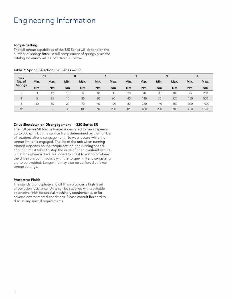
Torque SettingThe full torque capabilities of the 320 Series will depend on the number of springs fitted. A full complement of springs gives the catalog maximum values. See Table 21 below.
Drive Shutdown on Disengagement — 320 Series SRThe 320 Series SR torque limiter is designed to run at speeds up to 300 rpm, but the service life is determined by the number of rotations after disengagement. No wear occurs while the torque limiter is engaged. The life of the unit when running tripped depends on the torque setting, the running speed, and the time it takes to stop the drive after an overload occurs. Situations where a drive is allowed to coast to a stop or where the drive runs continuously with the torque limiter disengaging, are to be avoided. Longer life may also be achieved at lower torque settings.
Protective FinishThe standard phosphate and oil finish provides a high level of corrosion resistance. Units can be supplied with a suitable alternative finish for special machinery requirements, or for adverse environmental conditions. Please consult Rexnord to discuss any special requirements.
SizeNo. of Springs
01 0 1 2 3 4
Min. Max. Min. Max. Min. Max. Min. Max. Min. Max. Min. Max.
Nm Nm Nm Nm Nm Nm Nm Nm Nm Nm Nm Nm
2 3 12 10 17 10 30 20 70 35 100 75 250
4 5 25 10 35 20 60 40 140 70 225 150 500
8 10 50 20 70 40 120 80 260 140 450 300 1,000
12 - - 30 100 60 200 120 400 200 700 450 1,500
Table 7: Spring Selection 320 Series — SR
8
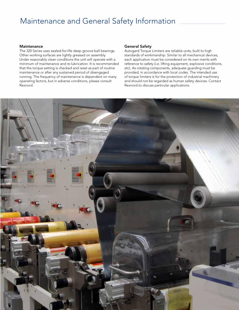
Maintenance and General Safety Information
Maintenance The 320 Series uses sealed-for-life deep groove ball bearings. Other working surfaces are lightly greased on assembly. Under reasonably clean conditions the unit will operate with a minimum of maintenance and re-lubrication. It is recommended that the torque setting is checked and reset as part of routine maintenance or after any sustained period of disengaged running. The frequency of maintenance is dependent on many operating factors, but in adverse conditions, please consult Rexnord.
General Safety Autogard Torque Limiters are reliable units, built to high standards of workmanship. Similar to all mechanical devices, each application must be considered on its own merits with reference to safety (i.e. lifting equipment, explosive conditions, etc). As rotating components, adequate guarding must be provided, in accordance with local codes. The intended use of torque limiters is for the protection of industrial machinery and should not be regarded as human safety devices. Contact Rexnord to discuss particular applications.
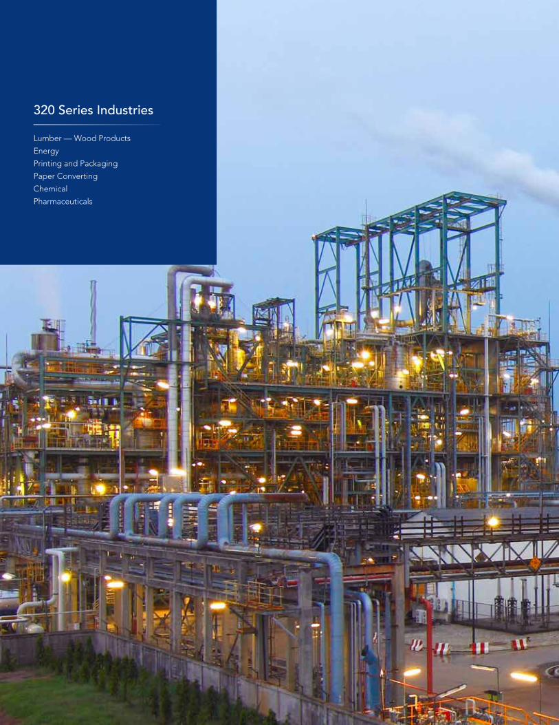
320 Series Industries
Lumber — Wood Products
Energy
Printing and Packaging
Paper Converting
Chemical
Pharmaceuticals
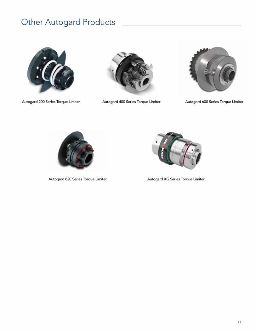
Autogard 600 Series Torque LimiterAutogard 200 Series Torque Limiter Autogard 400 Series Torque Limiter
Other Autogard Products
Autogard 820 Series Torque Limiter Autogard XG Series Torque Limiter
11
Why Choose Rexnord?When it comes to providing highly engineered products that improve productivity and efficiency for industrial applications worldwide, Rexnord is the most reliable in the industry. Commitment to customer satisfaction and superior value extend across every business function.
Delivering Lowest Total Cost of OwnershipThe highest quality products are designed to help prevent equipment downtime and increase productivity and dependable operation.
Valuable ExpertiseAn extensive product offering is accompanied by global sales specialists, customer service and maintenance support teams, available anytime.
Solutions to Enhance Ease of Doing BusinessCommitment to operational excellence ensures the right products at the right place at the right time.
UK: +44 1285 640333 Germany: +49 2129 912 2960
Australia: +61 3 9736 6002
China: +86 021 52436100India: +91 040 23078243
USA: 800-767-3539
www.rexnord.com
©2019 Rexnord TQ1-004 02/19
Rexnord Company OverviewRexnord is a growth-oriented, multi-platform industrial company with leading market shares and highly trusted brands that serve a diverse array of global end markets.
Process & Motion ControlThe Rexnord Process & Motion Control platform designs, manufactures, markets and services specified, highly engineered mechanical components used within complex systems where our customers’ reliability requirements and the cost of failure or downtime are extremely high.
Water ManagementThe Rexnord Water Management platform designs, procures, manufactures and markets products that provide and enhance water quality, safety, flow control and conservation.