Embed Size (px)
Citation preview
TORQUE LIMITERSERIES 320 MR
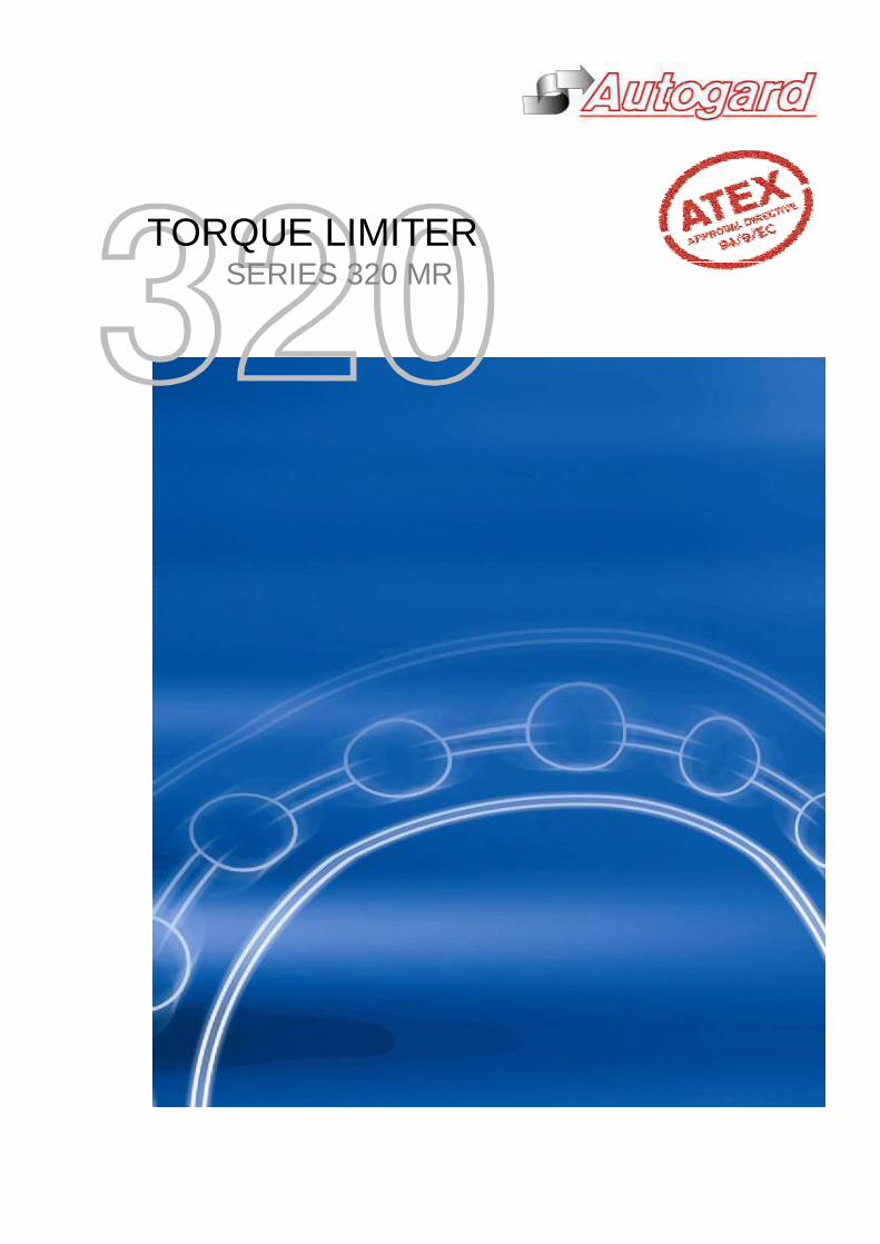
TORQUE LIMITERSERIES 320 MR
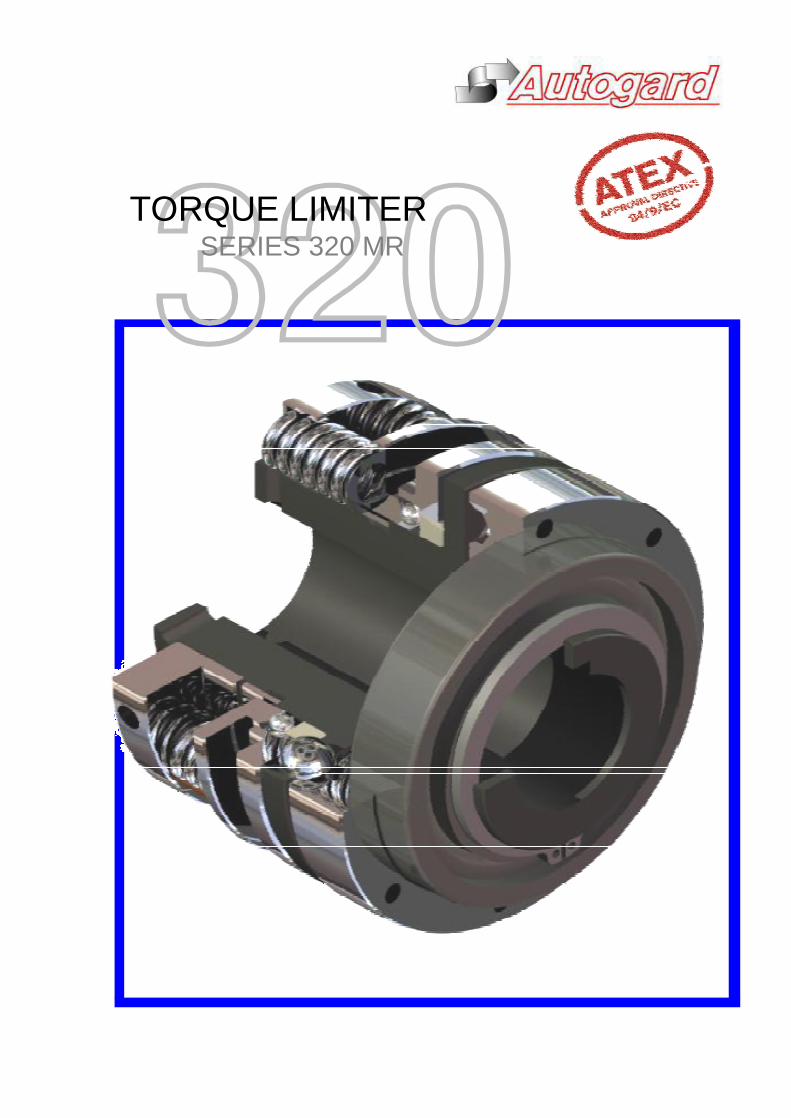
AUTOGARD SERIES 320 MR TORQUE LIMITERQuality and Autogard are synonymous with overload protection. The company's reputation for high quality products is derivedfrom over 40 years of design innovation and production. Autogard products are manufactured to meet ISO 9001 using the latestmachine tools and high quality materials.
EG
J
D
BA
C
The specifications contained within this brochure are correct at the time of going to print. Autogard is continuallyreviewing and updating the specifications on all its product ranges and therefore reserves the right to change any details.
1
The Autogard Series 320 MR (Manual Reset) mechanicaltorque limiter is specifically designed to run at high speedand capable of running continuously in the disengagedcondition.
The Series 320 MR torque limiter is a state of the artmechanical device that will disengage at a pre-set torquevalue. The trip torque is set above the normal start-upand operating torque, but below a torque setting whichwould normally damage the driving and /or drivenequipment.
In the event of a jam, the torque limiter eliminates thethreat of damage by disconnecting the inertia in the drivetrain.
The complete range of 320 MR torque limiters meet therequirements of ATEX approval under EU Directive94/9/EC, for Category 2 equipment.
Disengagement on OverloadIn the normal drive condition, torque is transmitted throughdrive balls (A) which are located in holes in flange (B) anddetents in drive plate (C). The drive balls are held in thedetents under pressure from springs (D)
When the driven machine either jams or an overload occurswhich is greater than the torque setting, the balls roll out oftheir seats pushing the pressure plate (E) and control balls(G) into a position such that the drive balls are held awayfrom the drive plate seats and the torque limiter can runfreely on bearing (J)
The axial movement of balls (A) during this process causespressure plate (E) to move and thereby provides a meansof detecting disengagement. An option sensor plate (H)may be attached to the pressur plate.
Re-engagement (Rapid Reset)The re-engagement of the torque limiter could not beeasier, simply insert a screwdriver (or similar) between thepressure plate and spring plate and twist slightly, the unitwill snap back into engagement, at any position.
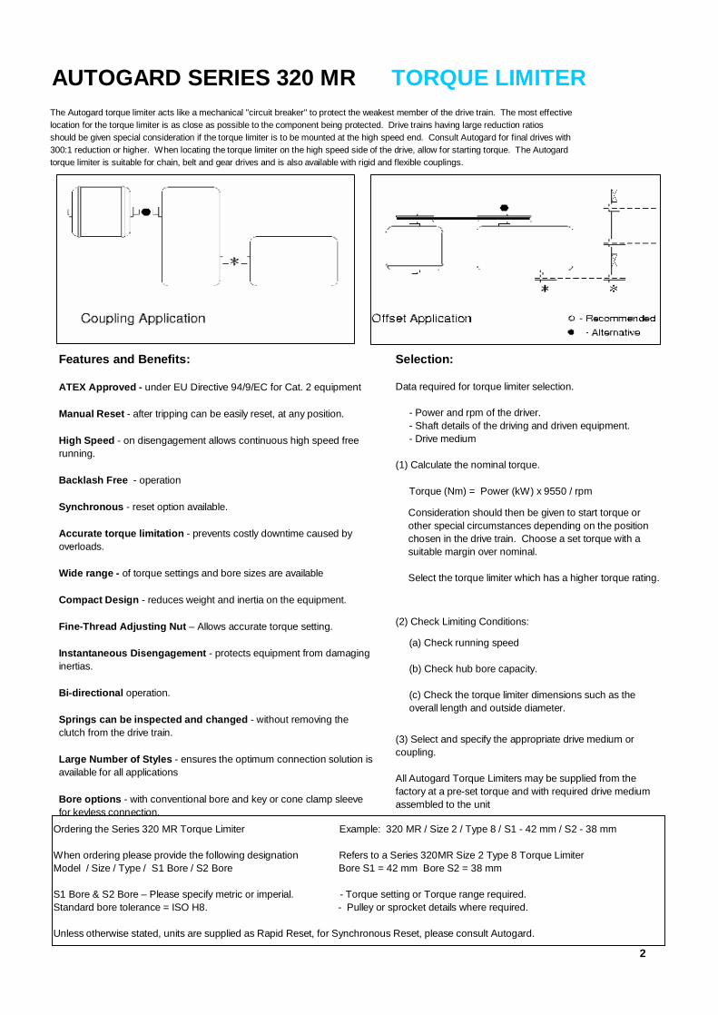
AUTOGARD SERIES 320 MR TORQUE LIMITERThe Autogard torque limiter acts like a mechanical "circuit breaker" to protect the weakest member of the drive train. The most effectivelocation for the torque limiter is as close as possible to the component being protected. Drive trains having large reduction ratiosshould be given special consideration if the torque limiter is to be mounted at the high speed end. Consult Autogard for final drives with300:1 reduction or higher. When locating the torque limiter on the high speed side of the drive, allow for starting torque. The Autogardtorque limiter is suitable for chain, belt and gear drives and is also available with rigid and flexible couplings.
2
Features and Benefits:
ATEX Approved - under EU Directive 94/9/EC for Cat. 2 equipment
Manual Reset - after tripping can be easily reset, at any position.
High Speed - on disengagement allows continuous high speed freerunning.
Backlash Free - operation
Synchronous - reset option available.
Accurate torque limitation - prevents costly downtime caused byoverloads.
Wide range - of torque settings and bore sizes are available
Compact Design - reduces weight and inertia on the equipment.
Fine-Thread Adjusting Nut – Allows accurate torque setting.
Instantaneous Disengagement - protects equipment from damaginginertias.
Bi-directional operation.
Springs can be inspected and changed - without removing theclutch from the drive train.
Large Number of Styles - ensures the optimum connection solution isavailable for all applications
Bore options - with conventional bore and key or cone clamp sleevefor keyless connection.
Selection:
Data required for torque limiter selection.
- Power and rpm of the driver. - Shaft details of the driving and driven equipment. - Drive medium
(1) Calculate the nominal torque.
Torque (Nm) = Power (kW) x 9550 / rpm
(2) Check Limiting Conditions:
(3) Select and specify the appropriate drive medium orcoupling.
All Autogard Torque Limiters may be supplied from thefactory at a pre-set torque and with required drive mediumassembled to the unit
Ordering the Series 320 MR Torque Limiter Example: 320 MR / Size 2 / Type 8 / S1 - 42 mm / S2 - 38 mm
When ordering please provide the following designation Refers to a Series 320MR Size 2 Type 8 Torque LimiterModel / Size / Type / S1 Bore / S2 Bore Bore S1 = 42 mm Bore S2 = 38 mm
S1 Bore & S2 Bore – Please specify metric or imperial. - Torque setting or Torque range required.Standard bore tolerance = ISO H8. - Pulley or sprocket details where required.
Unless otherwise stated, units are supplied as Rapid Reset, for Synchronous Reset, please consult Autogard.
Consideration should then be given to start torque orother special circumstances depending on the positionchosen in the drive train. Choose a set torque with asuitable margin over nominal.
Select the torque limiter which has a higher torque rating.
(a) Check running speed
(b) Check hub bore capacity.
(c) Check the torque limiter dimensions such as theoverall length and outside diameter.
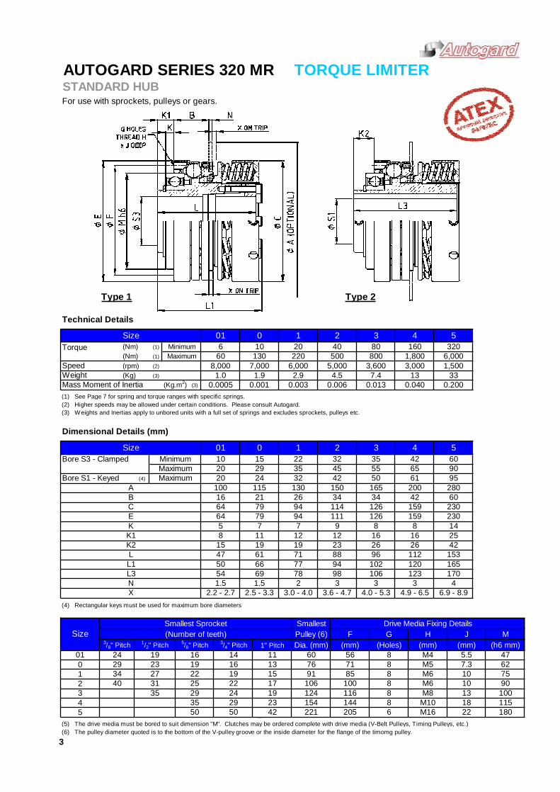
AUTOGARD SERIES 320 MR TORQUE LIMITERSTANDARD HUBFor use with sprockets, pulleys or gears.
Type 1 Type 2
Technical Details
(1)
(1)
(rpm) (2)
(3)
(3)
(1) See Page 7 for spring and torque ranges with specific springs.(2) Higher speeds may be allowed under certain conditions. Please consult Autogard.(3) Weights and Inertias apply to unbored units with a full set of springs and excludes sprockets, pulleys etc.
Dimensional Details (mm)
(4)
(4) Rectangular keys must be used for maximum bore diameters
1(5) The drive media must be bored to suit dimension "M". Clutches may be ordered complete with drive media (V-Belt Pulleys, Timing Pulleys, etc.)(6) The pulley diameter quoted is to the bottom of the V-pulley groove or the inside diameter for the flange of the timomg pulley.
100115180
47627590
165L3 54 69 78 98 106 123 170
77
11
71120
29
165 200
126 1597
16
94 102L1 50 66
6555
2
E126 159
350 1
94
6,000
42 60
13 330.040 0.200
Size 3 4
0.013
1,8003,000
0.006
MinimumMaximum
5
5
80 160 320
3 4
1,500800
7.4
6016 13
3/4" Pitch 1" Pitch
014 11
2329
Size1/2" Pitch
24 19
Smallest Sprocket(Number of teeth)
01
Drive Media Fixing DetailsM
(h6 mm)
SmallestPulley (6)Dia. (mm)
G
56 5.5
J(mm)
F H(mm)
15
124
7.376 7191 85
116106 100
35 24 1917
12 31 22
27 1934
3
3/8" Pitch
13
(Holes)
1010
(mm)M4M5
Torque (Nm)(Nm)
Speed
01 0 1 26 10 20 40
500
0.0030.0011.0 1.9 2.9 4.5
60 130 220
114
15 22 3235 45
8,000
Mass Moment of Inertia(Kg)
(Kg.m2) 0.0005Weight
L
01
Bore S1 - Keyed
8
A
Bore S3 - Clamped20
Size
MaximumMinimum
KK1
Maximum
10
5
9020 24 32 42 50 61 95
28016 21 26 34 34 42 60
130 150
3
925
8 8 1416
96 112
X
15388
12
2.2 - 2.7 2.5 - 3.3 3.0 - 4.0 3.6 - 4.7
12
47 61
4.0 - 5.3 4.9 - 6.5 6.9 - 8.9
64 79 94 111
42
3 3
100 115
C 64 79B
7,000 6,000 5,000 3,600
230
K2 15 19 19 23 26 26
2307
N 1.5 1.5 2 3 4
45
5/8" Pitch1619222529
88408
35 29 23 154
M6M6M8
88
144 8 M10 1850 50 M16 2242 221 205 6
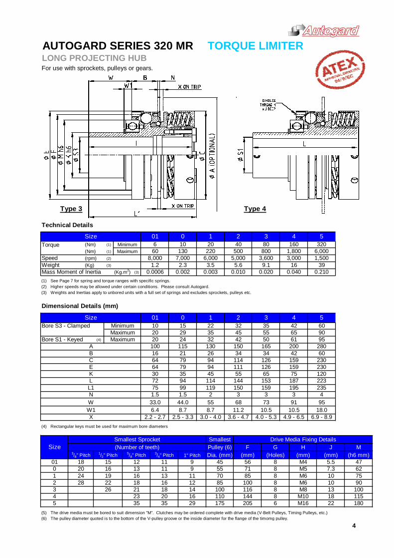
AUTOGARD SERIES 320 MR TORQUE LIMITERLONG PROJECTING HUBFor use with sprockets, pulleys or gears.
Type 3 Type 4
Technical Details
(1)
(1)
(rpm) (2)
(3)
(3)
(1) See Page 7 for spring and torque ranges with specific springs.(2) Higher speeds may be allowed under certain conditions. Please consult Autogard.(3) Weights and Inertias apply to unbored units with a full set of springs and excludes sprockets, pulleys etc.
Dimensional Details (mm)
(4)
(4) Rectangular keys must be used for maximum bore diameters
(5) The drive media must be bored to suit dimension "M". Clutches may be ordered complete with drive media (V-Belt Pulleys, Timing Pulleys, etc.)(6) The pulley diameter quoted is to the bottom of the V-pulley groove or the inside diameter for the flange of the timomg pulley.
M10M16
F(mm)
567185100116
M5M6M6M8
18.0
1013
7.3
Drive Media Fixing Details
(mm)
8
4
73 91 95
22 1808 18 115
10
W 33.0 44.0W1 6.4 8.7
29 175 620535 35
28
2326
20 14416 110
4
4.0 - 5.3 4.9 - 6.5 6.9 - 8.910.5 10.5
8
SmallestPulley (6)Dia. (mm)
45
45
5/8" Pitch12131618213
26 34 34
N 1.5 1.5 2 3 3
L
115
C 64 7916 21100
B
64 79 94
55
153 187
2.2 - 2.7 2.5 - 3.3 3.0 - 4.0
68
3.6 - 4.711.28.7
3
159 230230
72 94 114
11165 75 120
9535
223
12660
130 150
94 11442
32 42 50 61
3520
0
45
132
32
MaximumMaximum
280
90Bore S1 - Keyed
A
5520 24
500
0.0035.6
0.010
6,000 5,0001.2 2.3 3.5
8,000 7,000
01 0 1 2
Weight
Torque (Nm)(Nm)
Speed(Kg)
X
Minimum
K
8512 22 16
19 13
130 2206 10 20
24
18 141211
100
6255 870 8
100
7590
8
47
M(h6 mm)
G(mm)5.5
H
M4
J(Holes)
Size1/2" Pitch
18 15
Smallest Sprocket(Number of teeth)
013/8" Pitch 3/4" Pitch 1" Pitch
011 9
1620 11 9
9.13,0003,600
Size 3MinimumMaximum
4060
Mass Moment of Inertia
10 15 22
(Kg.m2) 0.0020.0006
01SizeBore S3 - Clamped
4
0.020
1,800
580 160 320
1,5006,000800
42 60
16 390.040 0.210
54
E
150 159L1 75 99
30 35 55144
235119 195
29
165 200
126 15945
65
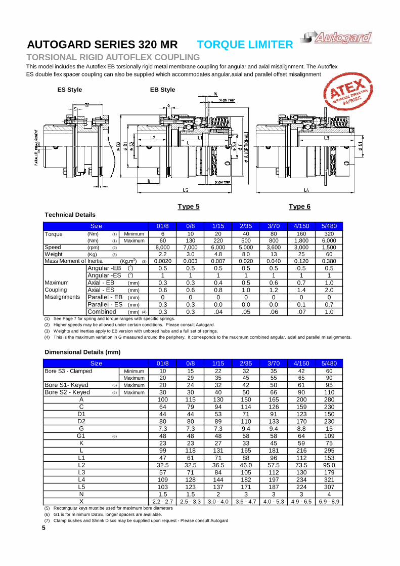
AUTOGARD SERIES 320 MR TORQUE LIMITERTORSIONAL RIGID AUTOFLEX COUPLINGThis model includes the Autoflex EB torsionally rigid metal membrane coupling for angular and axial misalignment. The AutoflexES double flex spacer coupling can also be supplied which accommodates angular,axial and parallel offset misalignment
Type 5 Type 6Technical Details
(1)
(1)
(rpm) (2)
(3)
(3)
Angular -EB (o)Angular -ES (o)Axial - EB (mm)Axial - ES (mm)Parallel - EB (mm)Parallel - ES (mm)Combined (mm) (4)
(1) See Page 7 for spring and torque ranges with specific springs.(2) Higher speeds may be allowed under certain conditions. Please consult Autogard.(3) Weights and Inertias apply to EB version with unbored hubs and a full set of springs.(4) This is the maximum variation in G measured around the periphery. It corresponds to the maximum combined angular, axial and parallel misalignments.
Dimensional Details (mm)
(5)
(5)
(6)
(5) Rectangular keys must be used for maximum bore diameters(6) G1 is for minimum DBSE, longer spacers are available.(7) Clamp bushes and Shrink Discs may be supplied upon request - Please consult Autogard
9045 55
197 234 321
57.5 73.5 95.0179
10 15
32.5
L4
29
57 71
30
G
D1
2020
24 32Bore S2 - Keyed Maximum
Minimum
Bore S1- KeyedMaximumMaximum
6.9 - 8.94.9 - 6.5
5
1.5 3 3 43.0 - 4.0 3.6 - 4.7 4.0 - 5.3
307187 2242 3
123 137 171109 128 144 182
84 105 112 13036.5 46.0
29547 61 71 88 15399 118 131 165
10923 23 27 33 45 59 75
48 58 58 649.4 8.8 15
4480 89 110 133 170 230
9.4
280
61 95
123 150
11042 50
90
71 91
150 16540 50
2/35
66
3/70
35
4/150
65
0/8 1/15
ES Style EB Style
0/8
1MaximumCouplingMisalignments 0
(Nm) 660(Nm)
1
0.6 0.8
Speed
0.5
0.3 0.3
(Kg)Mass Moment of Inertia 0.003
5/480
0.5
130Minimum 320
220 500
0.5 0.51
D2
0.6
30100
0
01/8Bore S3 - Clamped
C
Size
A
G1
L5
48
L132.5
103
16080
0.0020
20Maximum
40
253,000
(Kg.m2)
60
79 94 114 126 159 230
22 32 35
0.007
Size 01/810
Weight
Torque
96 112
0.020 0.040 0.120
1
181 216
0
42
115 130
44
7.3 7.3
64
7.3
53
48
2.2 - 2.7 2.5 - 3.3N 1.5
L3
K
L2
X
L
01.0
200
1/15 4/150
0.4 0.5
3/70
13
2/35 5/480
80
800 1,800 6,000
2.2 3.0 4.8 8.0 600.380
0.5 0.5 0.5
2.0
1 1 10.6 0.7 1.01.2 1.4
00.3 0.3 0.0 0.0 0.0 0.1 0.7
0 0
1.00.3 0.3 .04 .05 .07.06
1,5008,000 7,000 6,000 5,000 3,600
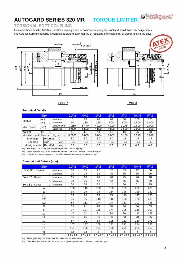
AUTOGARD SERIES 320 MR TORQUE LIMITERTORSIONAL SOFT COUPLINGThis model includes the Autoflex Samiflex coupling which accommodates angular, axial and parallel offset misalignmentsThe Autoflex Samiflex coupling provides a quick and easy method of replacing the insert and / or disconnecting the drive,
Type 7 Type 8
Technical Details
(1)
(1)
(3)
(3)
(o)(mm)(mm)
(1) See Page 7 for spring and torque ranges with specific springs.(2) Higher speeds may be allowed under certain conditions. Please consult Autogard.(3) Weights and Inertias apply to units with unbored hubs and a full set of springs.
Dimensional Details (mm)
(4)
(4)
Bore S1 - Keyed (4)
(4) Rectangular keys must be used for maximum bore diameters(5) Clamp bushes and Shrink Discs may be supplied upon request - Please consult Autogard
6
6.9 - 8.9
G 36 34 59
3 3 4X 2.2 - 2.7 2.5 - 3.3 3.0 - 4.0 3.6 - 4.7 4.0 - 5.3 4.9 - 6.5
20 29 35
3
15 21 28 30
N 1.5 1.5
L1 47 61
2
6,0004,200 3,275 2,800 2,000
224 319
170 233202 265
2/A3 3/A4 4/A45 5/A6160 320
1,800
25
180 201
42
L5 101 132 161191 211105
234 333L4 107 137 168112 130 179L3 57 71 84
112 153L2 35 45 56 56 63 70 95
71 88 96
116 116 150144 144 182
174
86D3 83 111D2 65
195 216 307L 97 127 155
Size 01/A1 0/A2 1/A3
Torque (Nm) Minimum 6(Nm) Maximum 60
10 20 40 80130 220 500 800
7,250 5,440 4,200Max. Speed UnbalancedBalanced
(rpm) (2)8,000 6,500
Weight (Kg) 1.9 4.0 7.1 8.6 16 73Mass Moment of Inertia (Kg.m2) 0.0020 0.009 0.034 0.037 0.130 0.220 0.620
D1 65 80 85 85 110 125 180
0.7 0.80.3 0.5 0.5 0.5+ 0.5 + 0.7
Maximum
0.7
Minimum 10Maximum
28 35
15
114 126 159 230C 64 79 94150 165 200 280100 115 130A
MaximumCoupling
Misalignments
AngularAxialParallel
1.3+ 0.52.0 2.0 2.0 2.0
+ 0.7 + 0.8+ 0.5 + 0.5
4,800 3,600 3,000
1.3 1.3
2,000
Size 01/A1 0/A2 1/A3 2/A3 3/A4 4/A45 5/A6
4,800
22 32 35 42 6045 55 65 90
25 26 40Minimum 15 18 20
24 32 42
2042
50 61 95
Bore S3 - Clamped
Bore S2 - Keyed55 65 90
Maximum 20
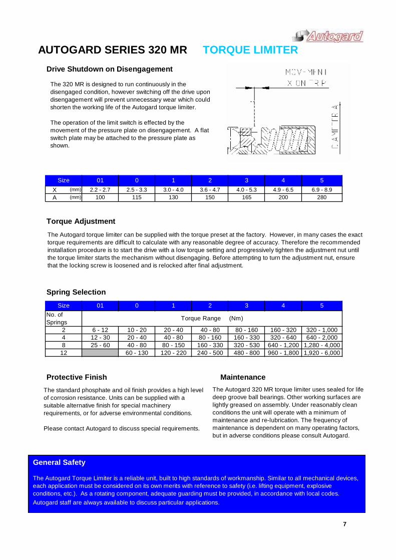
AUTOGARD SERIES 320 MR TORQUE LIMITERDrive Shutdown on Disengagement
Torque Adjustment
Spring Selection
Protective Finish Maintenance
01XA
22.2 - 2.7
100
Size 3 43.6 - 4.7 4.0 - 5.3 4.9 - 6.5
7
50 12.5 - 3.3 3.0 - 4.0 6.9 - 8.9
115 130 150 165 200 280
01 0 1 2 3 4 5SizeNo. ofSprings Torque Range (Nm)
2 10 - 20 20 - 40 40 - 80 80 - 160 160 - 320 320 - 1,00048
12
6 - 1212 - 3025 - 60 320 - 530 640 - 1,200 1,280 - 4,000
20 - 40 40 - 80 80 - 160 160 - 33040 - 80 80 - 150 160 - 330
960 - 1,800 1,920 - 6,000
(mm)(mm)
60 - 130 120 - 220 240 - 500 480 - 800
320 - 640 640 - 2,000
The Autogard torque limiter can be supplied with the torque preset at the factory. However, in many cases the exacttorque requirements are difficult to calculate with any reasonable degree of accuracy. Therefore the recommendedinstallation procedure is to start the drive with a low torque setting and progressively tighten the adjustment nut untilthe torque limiter starts the mechanism without disengaging. Before attempting to turn the adjustment nut, ensurethat the locking screw is loosened and is relocked after final adjustment.
The standard phosphate and oil finish provides a high levelof corrosion resistance. Units can be supplied with asuitable alternative finish for special machineryrequirements, or for adverse environmental conditions.
Please contact Autogard to discuss special requirements.
The Autogard 320 MR torque limiter uses sealed for lifedeep groove ball bearings. Other working surfaces arelightly greased on assembly. Under reasonably cleanconditions the unit will operate with a minimum ofmaintenance and re-lubrication. The frequency ofmaintenance is dependent on many operating factors,but in adverse conditions please consult Autogard.
General Safety
The Autogard Torque Limiter is a reliable unit, built to high standards of workmanship. Similar to all mechanical devices,each application must be considered on its own merits with reference to safety (i.e. lifting equipment, explosiveconditions, etc.). As a rotating component, adequate guarding must be provided, in accordance with local codes.Autogard staff are always available to discuss particular applications.
The 320 MR is designed to run continuously in thedisengaged condition, however switching off the drive upondisengagement will prevent unnecessary wear which couldshorten the working life of the Autogard torque limiter.
The operation of the limit switch is effected by themovement of the pressure plate on disengagement. A flatswitch plate may be attached to the pressure plate asshown.
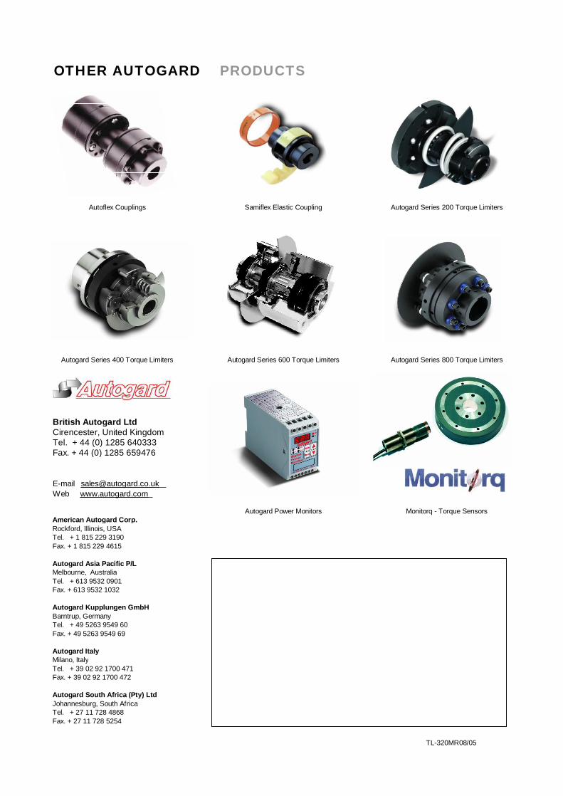
OTHER AUTOGARD PRODUCTS
British Autogard LtdCirencester, United KingdomTel. + 44 (0) 1285 640333Fax. + 44 (0) 1285 659476
E-mail [email protected] www.autogard.com
American Autogard Corp.Rockford, Illinois, USATel. + 1 815 229 3190Fax. + 1 815 229 4615
Autogard Asia Pacific P/LMelbourne, AustraliaTel. + 613 9532 0901Fax. + 613 9532 1032
Autogard Kupplungen GmbHBarntrup, GermanyTel. + 49 5263 9549 60Fax. + 49 5263 9549 69
Autogard ItalyMilano, ItalyTel. + 39 02 92 1700 471Fax. + 39 02 92 1700 472
Autogard South Africa (Pty) LtdJohannesburg, South AfricaTel. + 27 11 728 4868Fax. + 27 11 728 5254
TL-320MR08/05
Autogard Power Monitors Monitorq - Torque Sensors
Autoflex Couplings Samiflex Elastic Coupling
Autogard Series 600 Torque LimitersAutogard Series 400 Torque Limiters
Autogard Series 200 Torque Limiters
Autogard Series 800 Torque Limiters