Embed Size (px)
Citation preview
Publications No.
INSTALLATIONINSTRUCTIONS
Accessory Application
© 2015 American Honda Motor Co., Inc. – All Rights Re
VERSION 1
FOG LIGHTSserved. AII02174-44 (150
2016 ACCORD 4-DOOR
8) 0
Issue Date
AUG 2015
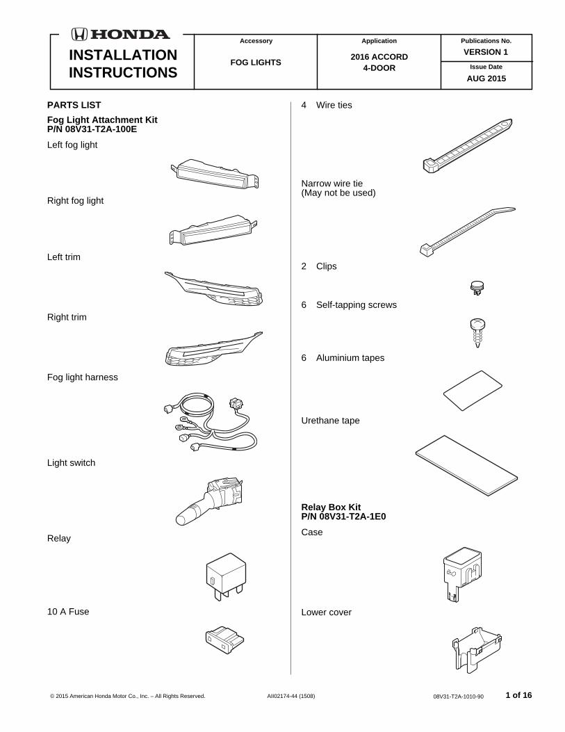
PARTS LIST
Fog Light Attachment KitP/N 08V31-T2A-100E
Left fog light
Right fog light
Left trim
Right trim
Fog light harness
Light switch
Relay
10 A Fuse
4 Wire ties
Narrow wire tie (May not be used)
2 Clips
6 Self-tapping screws
6 Aluminium tapes
Urethane tape
Relay Box KitP/N 08V31-T2A-1E0
Case
Lower cover
1 of 168V31-T2A-1010-90
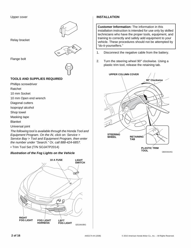
Upper cover
Relay bracket
Flange bolt
TOOLS AND SUPPLIES REQUIRED
Phillips screwdriver
Ratchet
10 mm Socket
10 mm Open end wrench
Diagonal cutters
Isopropyl alcohol
Shop towel
Masking tape
Blanket
Universal joint
The following tool is available through the Honda Tool and Equipment Program. On the iN, click on: Service > Service Bay > Tool and Equipment Program, then enter the number under “Search.” Or, call 888-424-6857.
• Trim Tool Set (T/N SOJATP2014)
Illustration of the Fog Lights on the Vehicle
QE22603BG
LIGHT SWITCH
LEFT FOG LIGHT
RIGHT FOG LIGHT FOG LIGHT
HARNESS
10 A FUSE
2 of 16 AII02174-4
INSTALLATION
Customer Information: The information in this installation instruction is intended for use only by skilled technicians who have the proper tools, equipment, and training to correctly and safely add equipment to your vehicle. These procedures should not be attempted by “do-it-yourselfers.”
1. Disconnect the negative cable from the battery.
2. Turn the steering wheel 90° clockwise. Using a plastic trim tool, release the retaining tab.
QB20302AG
RETAINING TAB
UPPER COLUMN COVER
PLASTIC TRIM TOOL
STEERING WHEEL
90° Clockwise
4 (1508) © 2015 American Honda Motor Co., Inc. – All Rights Reserved.
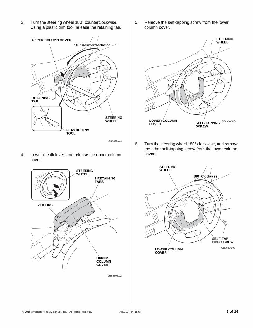
3. Turn the steering wheel 180° counterclockwise. Using a plastic trim tool, release the retaining tab.
QB20303AG
PLASTIC TRIM TOOL
UPPER COLUMN COVER
STEERING WHEEL
RETAINING TAB
180° Counterclockwise
4. Lower the tilt lever, and release the upper column cover.
QB51801AG
UPPER COLUMN COVER
2 RETAINING TABS
2 HOOKS
STEERING WHEEL
© 2015 American Honda Motor Co., Inc. – All Rights Reserved. AII02174-4
5. Remove the self-tapping screw from the lower column cover.
QB20305AGLOWER COLUMN COVER
STEERING WHEEL
SELF-TAPPING SCREW
6. Turn the steering wheel 180° clockwise, and remove the other self-tapping screw from the lower column cover.
QB20306AGLOWER COLUMN COVER
SELF-TAP-PING SCREW
180° Clockwise
STEERING WHEEL
4 (1508) 3 of 16
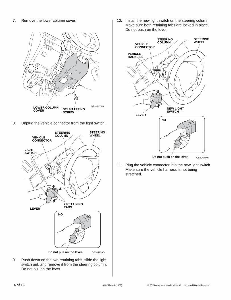
7. Remove the lower column cover.
QB20307AGSELF-TAPPING SCREW
LOWER COLUMN COVER
8. Unplug the vehicle connector from the light switch.
QE30423AG
LIGHT SWITCH
STEERING COLUMN
2 RETAINING TABSLEVER
VEHICLE CONNECTOR
STEERING WHEEL
Do not pull on the lever.
NO
9. Push down on the two retaining tabs, slide the light switch out, and remove it from the steering column. Do not pull on the lever.
4 of 16 AII02174-4
10. Install the new light switch on the steering column. Make sure both retaining tabs are locked in place. Do not push on the lever.
QE30424AG
STEERING COLUMN
LEVER
VEHICLE CONNECTOR
STEERING WHEEL
NEW LIGHT SWITCH
VEHICLE HARNESS
NO
Do not push on the lever.
11. Plug the vehicle connector into the new light switch. Make sure the vehicle harness is not being stretched.
4 (1508) © 2015 American Honda Motor Co., Inc. – All Rights Reserved.
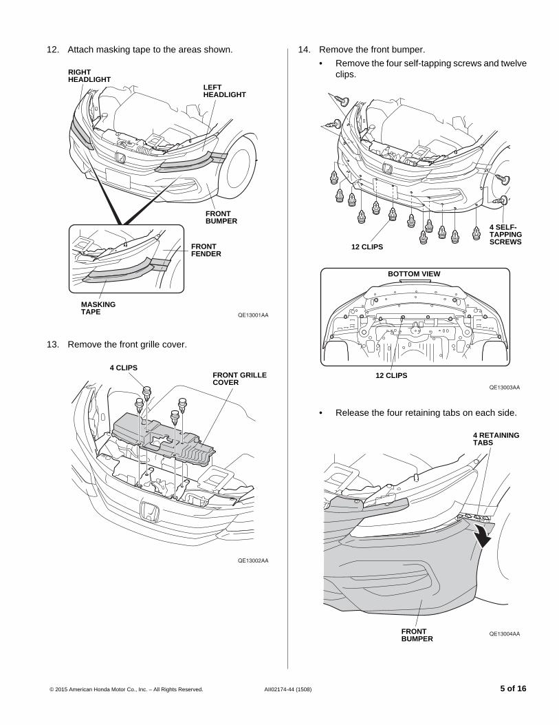
12. Attach masking tape to the areas shown.
QE13001AA
LEFT HEADLIGHT
RIGHT HEADLIGHT
FRONT BUMPER
FRONT FENDER
MASKING TAPE
13. Remove the front grille cover.
QE13002AA
FRONT GRILLE COVER
4 CLIPS
© 2015 American Honda Motor Co., Inc. – All Rights Reserved. AII02174-4
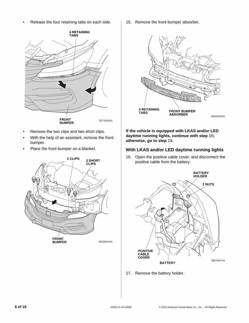
14. Remove the front bumper.
• Remove the four self-tapping screws and twelve clips.
QE13003AA
12 CLIPS
12 CLIPS
BOTTOM VIEW
4 SELF-TAPPING SCREWS
• Release the four retaining tabs on each side.
QE13004AA
4 RETAINING TABS
FRONT BUMPER
4 (1508) 5 of 16
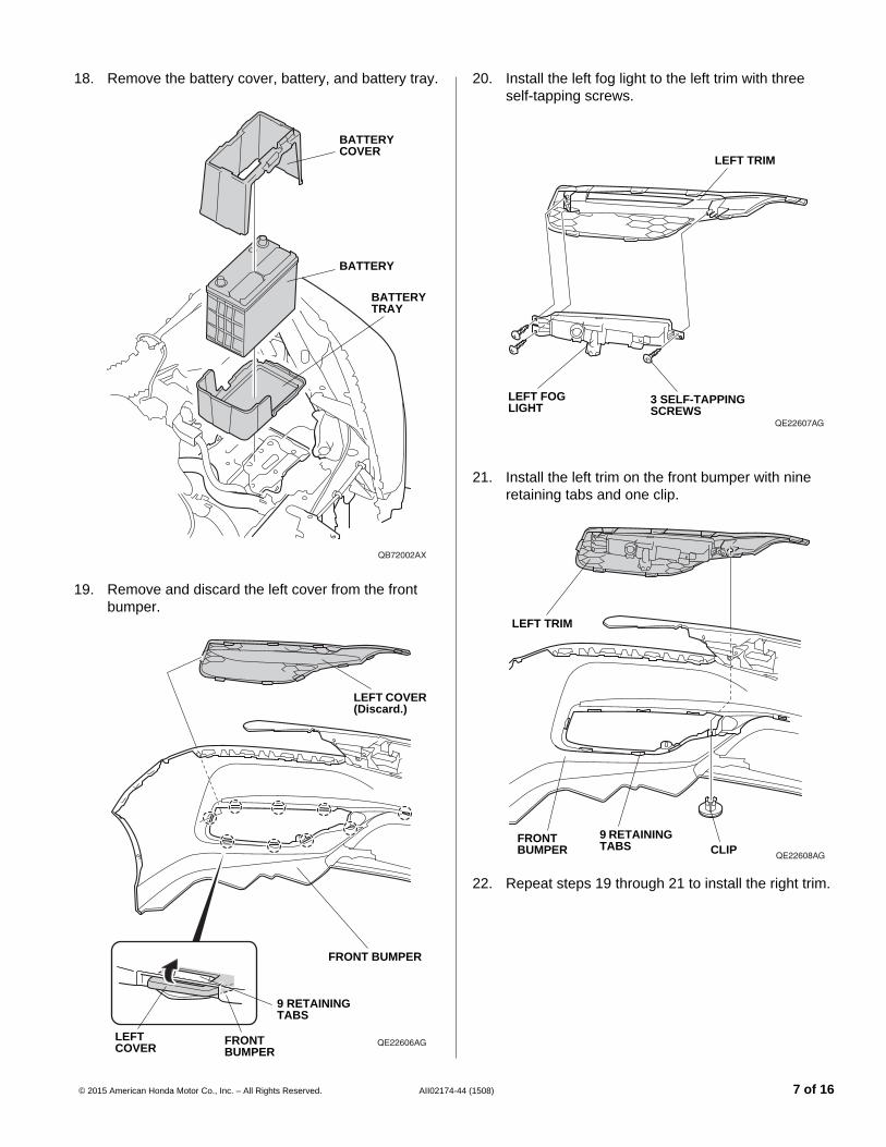
• Release the four retaining tabs on each side.
QE13005AA
4 RETAINING TABS
FRONT BUMPER
• Remove the two clips and two short clips.
• With the help of an assistant, remove the front bumper.
• Place the front bumper on a blanket.
QE22604AGFRONT BUMPER
2 CLIPS 2 SHORT CLIPS
6 of 16 AII02174-4
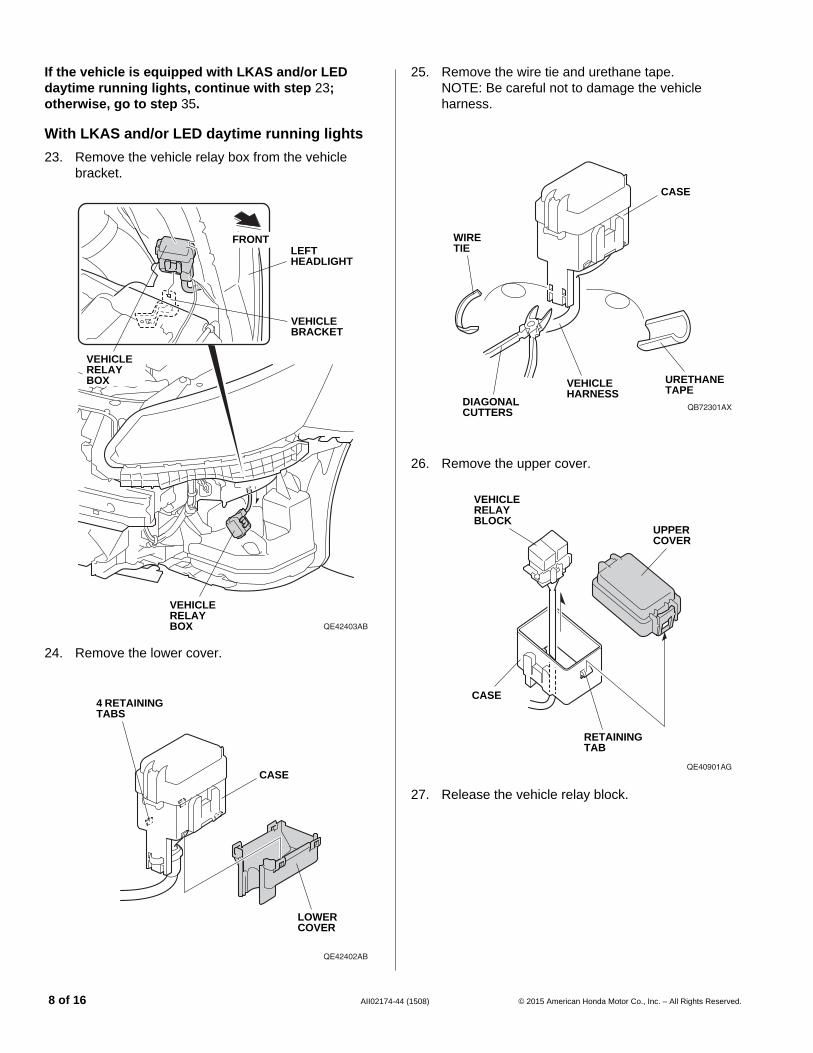
15. Remove the front bumper absorber.
QE22605AG
FRONT BUMPER ABSORBER
4 RETAINING TABS
If the vehicle is equipped with LKAS and/or LED daytime running lights, continue with step 16; otherwise, go to step 19.
With LKAS and/or LED daytime running lights
16. Open the positive cable cover, and disconnect the positive cable from the battery.
QB72001AX
2 NUTS
POSITIVE CABLE COVER
BATTERY
BATTERY HOLDER
17. Remove the battery holder.
4 (1508) © 2015 American Honda Motor Co., Inc. – All Rights Reserved.
18. Remove the battery cover, battery, and battery tray.
QB72002AX
BATTERY COVER
BATTERY
BATTERY TRAY
19. Remove and discard the left cover from the front bumper.
QE22606AG
FRONT BUMPER
LEFT COVER (Discard.)
9 RETAINING TABS
LEFT COVER
FRONT BUMPER
© 2015 American Honda Motor Co., Inc. – All Rights Reserved. AII02174-4
20. Install the left fog light to the left trim with three self-tapping screws.
QE22607AG
3 SELF-TAPPING SCREWS
LEFT FOG LIGHT
LEFT TRIM
21. Install the left trim on the front bumper with nine retaining tabs and one clip.
QE22608AG
FRONT BUMPER
LEFT TRIM
9 RETAINING TABS CLIP
22. Repeat steps 19 through 21 to install the right trim.
4 (1508) 7 of 16
If the vehicle is equipped with LKAS and/or LED daytime running lights, continue with step 23; otherwise, go to step 35.
With LKAS and/or LED daytime running lights
23. Remove the vehicle relay box from the vehicle bracket.
QE42403AB
FRONT
VEHICLE RELAY BOX
VEHICLE BRACKET
LEFT HEADLIGHT
VEHICLE RELAY BOX
24. Remove the lower cover.
QE42402AB
CASE
LOWER COVER
4 RETAINING TABS
8 of 16 AII02174-4
25. Remove the wire tie and urethane tape. NOTE: Be careful not to damage the vehicle harness.
QB72301AXDIAGONAL CUTTERS
CASE
WIRE TIE
VEHICLE HARNESS
URETHANE TAPE
26. Remove the upper cover.
QE40901AG
UPPER COVER
VEHICLE RELAY BLOCK
CASE
RETAINING TAB
27. Release the vehicle relay block.
4 (1508) © 2015 American Honda Motor Co., Inc. – All Rights Reserved.
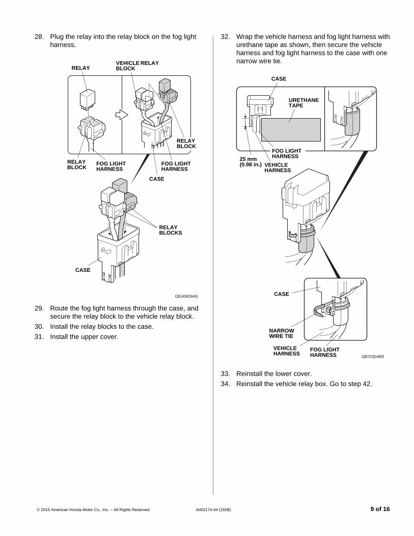
28. Plug the relay into the relay block on the fog light harness.
QE40903AG
FOG LIGHT HARNESS
VEHICLE RELAY BLOCK
RELAY BLOCK
RELAY BLOCK
FOG LIGHT HARNESS
RELAY
CASE
RELAY BLOCKS
CASE
29. Route the fog light harness through the case, and secure the relay block to the vehicle relay block.
30. Install the relay blocks to the case.
31. Install the upper cover.
© 2015 American Honda Motor Co., Inc. – All Rights Reserved. AII02174-4
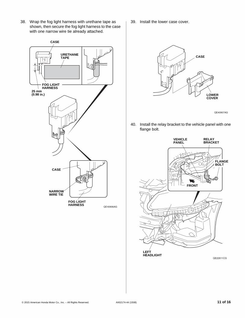
32. Wrap the vehicle harness and fog light harness with urethane tape as shown, then secure the vehicle harness and fog light harness to the case with one narrow wire tie.
QB72304BX
FOG LIGHT HARNESS
CASE
NARROW WIRE TIE
CASE
URETHANE TAPE
25 mm (0.98 in.)
FOG LIGHT HARNESS
VEHICLE HARNESS
VEHICLE HARNESS
33. Reinstall the lower cover.
34. Reinstall the vehicle relay box. Go to step 42.
4 (1508) 9 of 16

Without LKAS and/or LED daytime running lights
35. Plug the relay into the relay block on the fog light harness.
FOG LIGHT HARNESS
RELAY BLOCK
FOG LIGHT HARNESS
RELAY
CASE
RELAY BLOCK
CASE
36. Route the fog light harness through the case, and install the relay block in the case.
10 of 16 AII02174-4
37. Install the upper case cover.
UPPER COVER
CASE
4 (1508) © 2015 American Honda Motor Co., Inc. – All Rights Reserved.
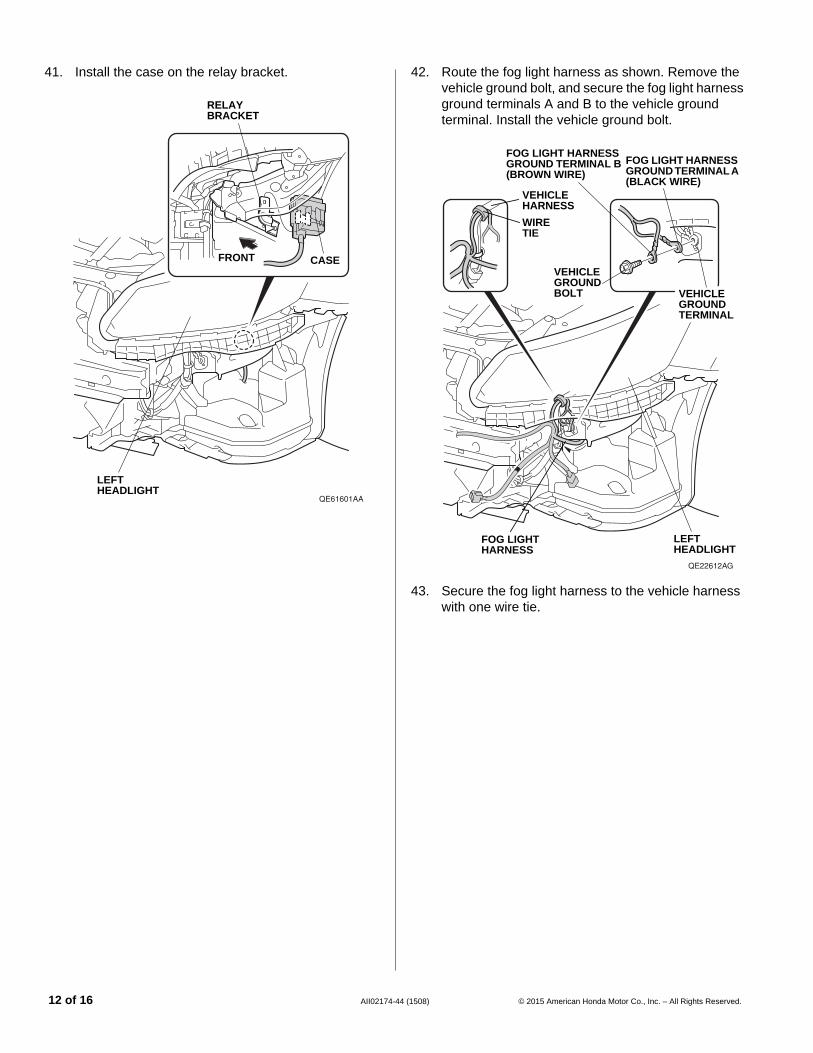
38. Wrap the fog light harness with urethane tape as shown, then secure the fog light harness to the case with one narrow wire tie already attached.
QE40906AG
FOG LIGHT HARNESS
CASE
NARROW WIRE TIE
CASE
URETHANE TAPE
25 mm (0.98 in.)
FOG LIGHT HARNESS
© 2015 American Honda Motor Co., Inc. – All Rights Reserved. AII02174-4
39. Install the lower case cover.
QE40907AG
LOWER COVER
CASE
40. Install the relay bracket to the vehicle panel with one flange bolt.
QE22611CG
VEHICLE PANEL
LEFT HEADLIGHT
FRONT
FLANGE BOLT
RELAY BRACKET
4 (1508) 11 of 16
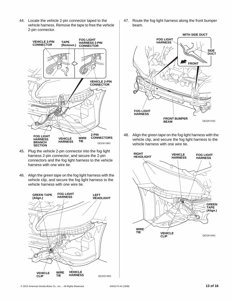
41. Install the case on the relay bracket.
QE61601AA
LEFT HEADLIGHT
FRONT CASE
RELAY BRACKET
12 of 16 AII02174-4
42. Route the fog light harness as shown. Remove the vehicle ground bolt, and secure the fog light harness ground terminals A and B to the vehicle ground terminal. Install the vehicle ground bolt.
QE22612AG
LEFT HEADLIGHT
VEHICLE GROUND BOLT
FOG LIGHT HARNESS GROUND TERMINAL A (BLACK WIRE)
VEHICLE GROUND TERMINAL
FOG LIGHT HARNESS GROUND TERMINAL B (BROWN WIRE)
VEHICLE HARNESS
WIRE TIE
FOG LIGHT HARNESS
43. Secure the fog light harness to the vehicle harness with one wire tie.
4 (1508) © 2015 American Honda Motor Co., Inc. – All Rights Reserved.
44. Locate the vehicle 2-pin connector taped to the vehicle harness. Remove the tape to free the vehicle 2-pin connector.
QE22613BG
WIRE TIE
VEHICLE HARNESS
2-PIN CONNECTORS
VEHICLE 2-PIN CONNECTOR
TAPE (Remove.)
FOG LIGHT HARNESS 2-PIN CONNECTOR
VEHICLE 2-PIN CONNECTOR
FOG LIGHT HARNESS BRANCH SECTION
45. Plug the vehicle 2-pin connector into the fog light harness 2-pin connector, and secure the 2-pin connectors and the fog light harness to the vehicle harness with one wire tie.
46. Align the green tape on the fog light harness with the vehicle clip, and secure the fog light harness to the vehicle harness with one wire tie.
QE22614BG
LEFT HEADLIGHT
FOG LIGHT HARNESS
GREEN TAPE (Align.)
VEHICLE HARNESS
WIRE TIE
VEHICLE CLIP
© 2015 American Honda Motor Co., Inc. – All Rights Reserved. AII02174-4
47. Route the fog light harness along the front bumper beam.
QE22615AG
FOG LIGHT HARNESS
FOG LIGHT HARNESS
FRONT BUMPER BEAM
FRONT
SIDE DUCT
WITH SIDE DUCT
48. Align the green tape on the fog light harness with the vehicle clip, and secure the fog light harness to the vehicle harness with one wire tie.
QE22616AG
FOG LIGHT HARNESS
VEHICLE HARNESS
RIGHT HEADLIGHT
GREEN TAPE (Align.)
VEHICLE CLIP
WIRE TIE
4 (1508) 13 of 16
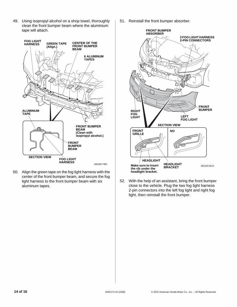
49. Using isopropyl alcohol on a shop towel, thoroughly clean the front bumper beam where the aluminium tape will attach.
QE22617BG
FRONT BUMPER BEAM (Clean with isopropyl alcohol.)
GREEN TAPE (Align.)
FOG LIGHT HARNESS
6 ALUMINUM TAPES
CENTER OF THE FRONT BUMPER BEAM
SECTION VIEW
ALUMINUM TAPE
FOG LIGHT HARNESS
FRONT BUMPER BEAM
50. Align the green tape on the fog light harness with the center of the front bumper beam, and secure the fog light harness to the front bumper beam with six aluminum tapes.
14 of 16 AII02174-4
51. Reinstall the front bumper absorber.
QE22618CG
FRONT BUMPER
2 FOG LIGHT HARNESS 2-PIN CONNECTORS
RIGHT FOG LIGHT LEFT
FOG LIGHT
FRONT BUMPER ABSORBER
NOFRONT GRILLE
Make sure to insert the rib under the headlight bracket.
HEADLIGHT
SECTION VIEW
HEADLIGHT BRACKET
52. With the help of an assistant, bring the front bumper close to the vehicle. Plug the two fog light harness 2-pin connectors into the left fog light and right fog light, then reinstall the front bumper.
4 (1508) © 2015 American Honda Motor Co., Inc. – All Rights Reserved.
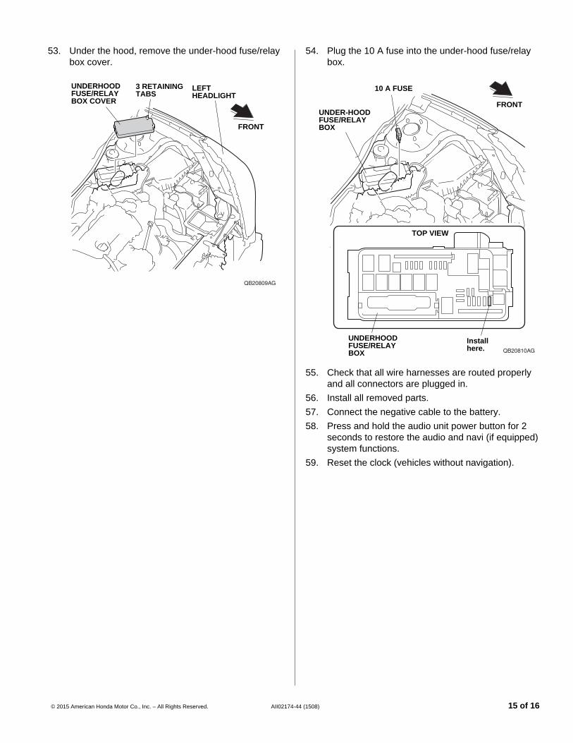
53. Under the hood, remove the under-hood fuse/relay box cover.
QB20809AG
UNDERHOOD FUSE/RELAY BOX COVER
FRONT
3 RETAINING TABS
LEFT HEADLIGHT
© 2015 American Honda Motor Co., Inc. – All Rights Reserved. AII02174-4
54. Plug the 10 A fuse into the under-hood fuse/relay box.
QB20810AG
TOP VIEW
Install here.
FRONTUNDER-HOOD FUSE/RELAY BOX
10 A FUSE
UNDERHOOD FUSE/RELAY BOX
55. Check that all wire harnesses are routed properly and all connectors are plugged in.
56. Install all removed parts.
57. Connect the negative cable to the battery.
58. Press and hold the audio unit power button for 2 seconds to restore the audio and navi (if equipped) system functions.
59. Reset the clock (vehicles without navigation).
4 (1508) 15 of 16
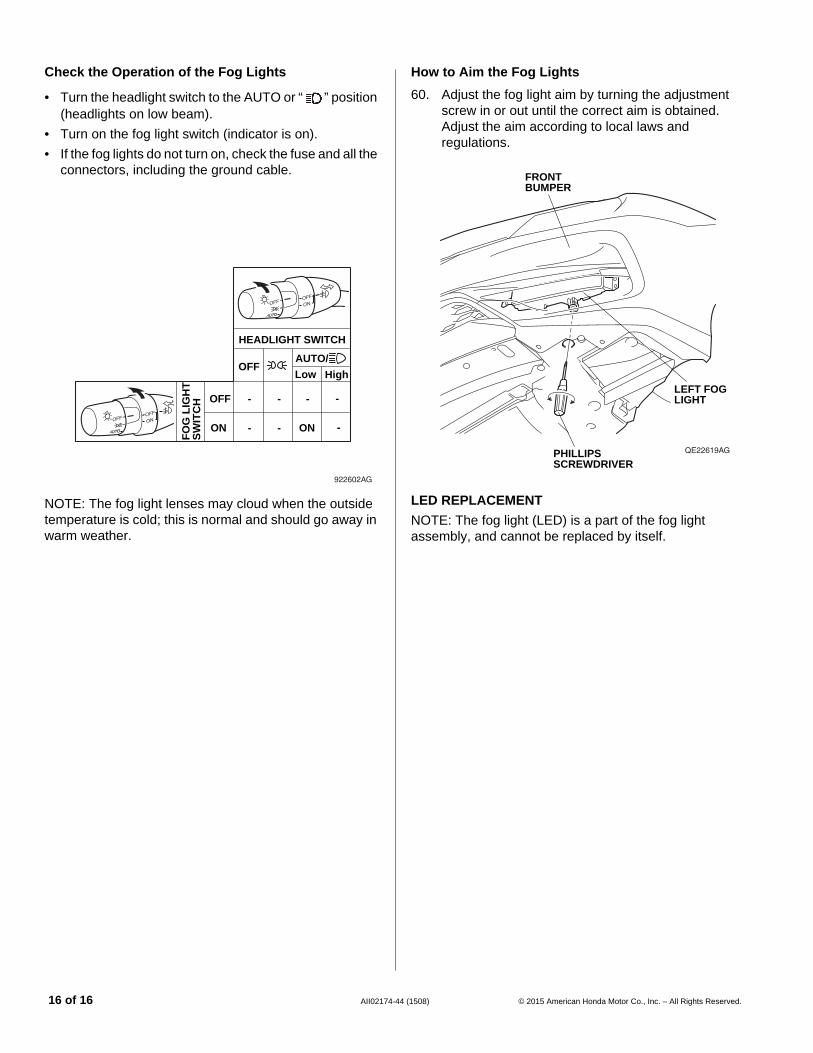
Check the Operation of the Fog Lights
• Turn the headlight switch to the AUTO or “ ” position (headlights on low beam).
• Turn on the fog light switch (indicator is on).
• If the fog lights do not turn on, check the fuse and all the connectors, including the ground cable.
922602AG
FO
G L
IGH
T
SW
ITC
H
HEADLIGHT SWITCH
Low HighOFF
ON
OFF - - - -
- - -ON
AUTO/
NOTE: The fog light lenses may cloud when the outside temperature is cold; this is normal and should go away in warm weather.
16 of 16 AII02174-4
How to Aim the Fog Lights
60. Adjust the fog light aim by turning the adjustment screw in or out until the correct aim is obtained. Adjust the aim according to local laws and regulations.
QE22619AG
LEFT FOG LIGHT
FRONT BUMPER
PHILLIPS SCREWDRIVER
LED REPLACEMENT
NOTE: The fog light (LED) is a part of the fog light assembly, and cannot be replaced by itself.
4 (1508) © 2015 American Honda Motor Co., Inc. – All Rights Reserved.