Embed Size (px)
Citation preview
© 2001 American Honda Motor Co., Inc - All Rights Reserved. AII 23073 (0111) 1 of 1508V31-S9A-1000-91
PARTS LIST
Left fog light
Right fog light
Left fog light trim
Fog light harness
Switch harness
Switch
2 Relays
Fuse label
Relay bracket
21 Wire ties
Wire tie with clip, brown
Wire tie with clip, black
4 Washer-bolts, 6 x 16 mm
4 Large spring nuts
2 Self-tapping screw, 5 x 12 mm
2 Small spring nuts
4 Step screws
2 Washer-screws, 4 x 8 mm
Right fog light trim
INSTALLATIONINSTRUCTIONS
Accessory Application Publications No.
Issue Date
NOV 2001
2002 CR-VFOG LIGHTP/N 08V31-S9A-110
All 23073
Y0599C
2 of 15 AII 23073 (0111) © 2001 American Honda Motor Co., Inc - All Rights Reserved.
TOOL AND SUPPLIES REQUIRED
Phillips screwdriver
Flat-tip screwdriver
Ratchet
10 mm and 14 mm socket
File
Torque wrench
Utility knife
Duct tape
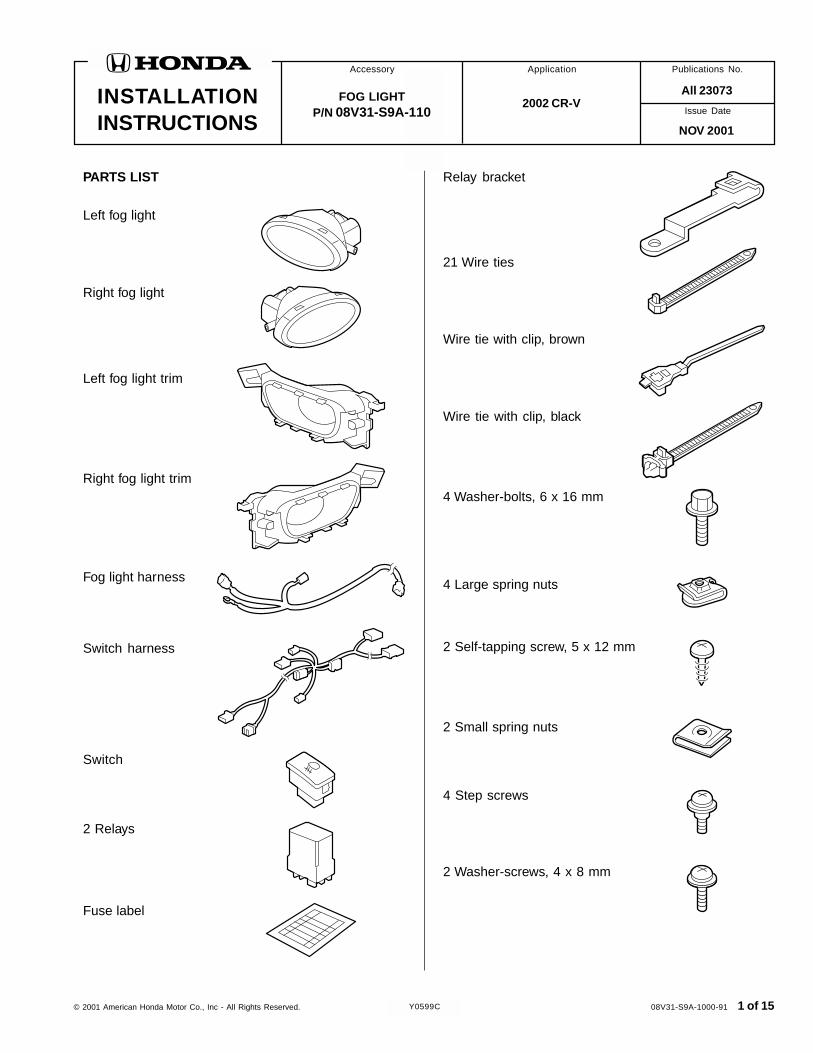
Illustration of the Fog Light Installed on theVehicle
FOG LIGHT HARNESS SWITCH HARNESS
FOG LIGHTSWITCH
RELAY
LEFT FOG LIGHT
RIGHT FOG LIGHT
INSTALLATION
Customer Information: The information in thisinstallation instruction is intended for use only byskilled technicians who have the proper tools,equipment, and training to correctly and safely addequipment to your vehicle. These proceduresshould not be attempted by “do-it-yourselfers.”
Left fog light adjuster
Right fog light adjuster
2 Fog light brackets
Harness bracket
2 Wire tie with clip, white
8 Self-tapping screws, 5 x 16 mm
NOTE: These installation instruction show the left foglight begin installed. The same procedure applies toinstalling the right fog light.
1. Make sure you have the anti-theft code for theradio, then write down the frequencies for thepreset buttons.
2. Disconnect the negative cable from the battery.
2 Rubber trims
FUSE CASE
© 2001 American Honda Motor Co., Inc - All Rights Reserved. AII 23073 (0111) 3 of 15
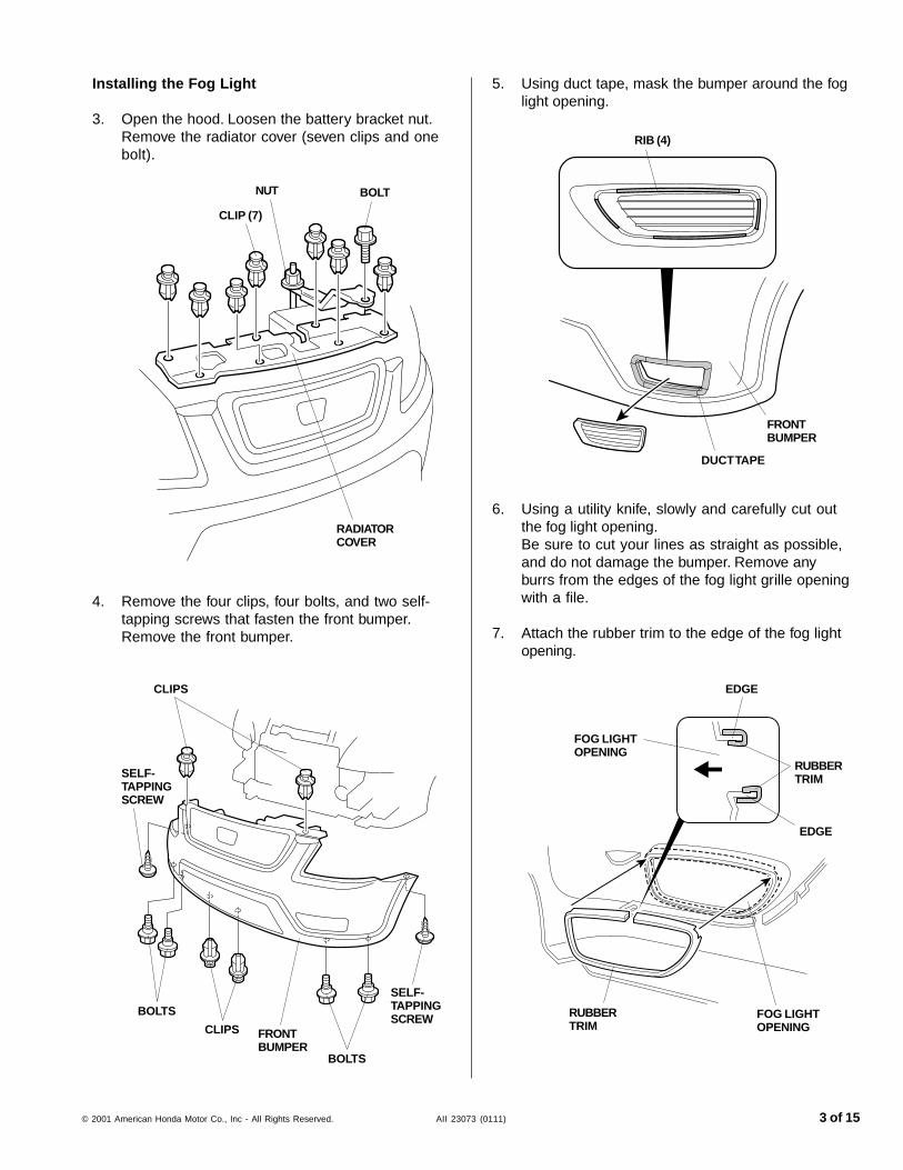
5. Using duct tape, mask the bumper around the foglight opening.
DUCT TAPE
6. Using a utility knife, slowly and carefully cut outthe fog light opening.Be sure to cut your lines as straight as possible,and do not damage the bumper. Remove anyburrs from the edges of the fog light grille openingwith a file.
7. Attach the rubber trim to the edge of the fog lightopening.
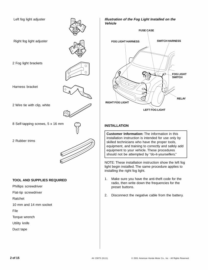
BOLT
CLIP (7)
RADIATORCOVER
Installing the Fog Light
3. Open the hood. Loosen the battery bracket nut.Remove the radiator cover (seven clips and onebolt).
RIB (4)
FRONTBUMPER
FOG LIGHTOPENING
EDGE
EDGE
RUBBERTRIM
FOG LIGHTOPENING
RUBBERTRIM
4. Remove the four clips, four bolts, and two self-tapping screws that fasten the front bumper.Remove the front bumper.
FRONTBUMPER
CLIPS
CLIPS
BOLTS
SELF-TAPPINGSCREW
SELF-TAPPINGSCREW
BOLTS
NUT
4 of 15 AII 23073 (0111) © 2001 American Honda Motor Co., Inc - All Rights Reserved.
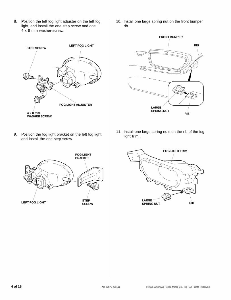
RIB
FOG LIGHT TRIM
11. Install one large spring nuts on the rib of the foglight trim.
LARGESPRING NUT
8. Position the left fog light adjuster on the left foglight, and install the one step screw and one4 x 8 mm washer-screw.
STEP SCREWLEFT FOG LIGHT
4 x 8 mmWASHER SCREW
FOG LIGHT ADJUSTER
9. Position the fog light bracket on the left fog light,and install the one step screw.
LEFT FOG LIGHT
FOG LIGHTBRACKET
STEPSCREW
10. Install one large spring nut on the front bumperrib.
FRONT BUMPER
RIB
LARGESPRING NUT
RIB
© 2001 American Honda Motor Co., Inc - All Rights Reserved. AII 23073 (0111) 5 of 15
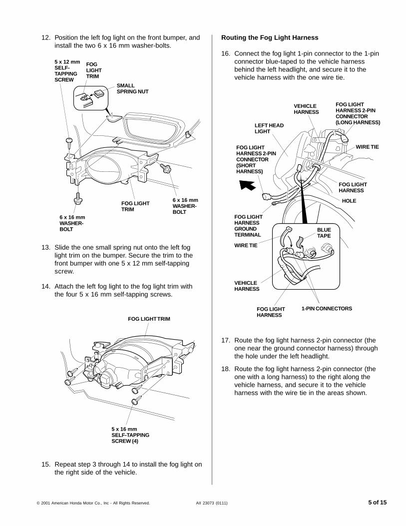
Routing the Fog Light Harness
16. Connect the fog light 1-pin connector to the 1-pinconnector blue-taped to the vehicle harnessbehind the left headlight, and secure it to thevehicle harness with the one wire tie.
17. Route the fog light harness 2-pin connector (theone near the ground connector harness) throughthe hole under the left headlight.
18. Route the fog light harness 2-pin connector (theone with a long harness) to the right along thevehicle harness, and secure it to the vehicleharness with the wire tie in the areas shown.
14. Attach the left fog light to the fog light trim withthe four 5 x 16 mm self-tapping screws.
5 x 16 mmSELF-TAPPINGSCREW (4)
FOG LIGHT TRIM
15. Repeat step 3 through 14 to install the fog light onthe right side of the vehicle.
12. Position the left fog light on the front bumper, andinstall the two 6 x 16 mm washer-bolts.
FOGLIGHTTRIM
SMALLSPRING NUT
5 x 12 mmSELF-TAPPINGSCREW
6 x 16 mmWASHER-BOLT
6 x 16 mmWASHER-BOLT
FOG LIGHTTRIM
LEFT HEADLIGHT
FOG LIGHTHARNESS
VEHICLEHARNESS
1-PIN CONNECTORS
BLUETAPE
WIRE TIE
FOG LIGHTHARNESSGROUNDTERMINAL
HOLE
FOG LIGHTHARNESS 2-PINCONNECTOR(SHORTHARNESS)
FOG LIGHTHARNESS 2-PINCONNECTOR(LONG HARNESS)
WIRE TIE
VEHICLEHARNESS
FOG LIGHTHARNESS
13. Slide the one small spring nut onto the left foglight trim on the bumper. Secure the trim to thefront bumper with one 5 x 12 mm self-tappingscrew.
6 of 15 AII 23073 (0111) © 2001 American Honda Motor Co., Inc - All Rights Reserved.
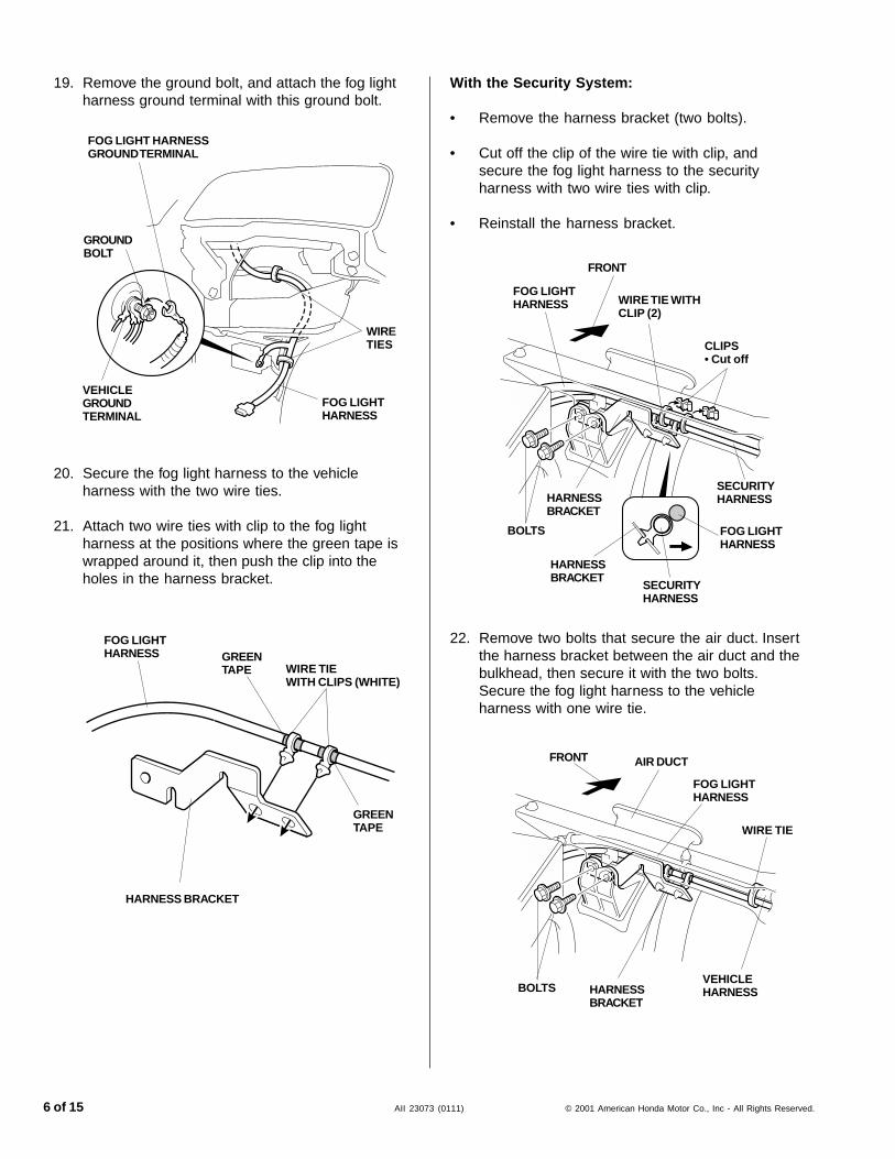
With the Security System:
• Remove the harness bracket (two bolts).
• Cut off the clip of the wire tie with clip, andsecure the fog light harness to the securityharness with two wire ties with clip.
• Reinstall the harness bracket.
20. Secure the fog light harness to the vehicleharness with the two wire ties.
21. Attach two wire ties with clip to the fog lightharness at the positions where the green tape iswrapped around it, then push the clip into theholes in the harness bracket.
BOLTS
FRONT
19. Remove the ground bolt, and attach the fog lightharness ground terminal with this ground bolt.
AIR DUCT
22. Remove two bolts that secure the air duct. Insertthe harness bracket between the air duct and thebulkhead, then secure it with the two bolts.Secure the fog light harness to the vehicleharness with one wire tie.
WIRE TIEWITH CLIPS (WHITE)
FOG LIGHTHARNESS
GREENTAPE
GREENTAPE
HARNESSBRACKET
FOG LIGHTHARNESS
WIRE TIE WITHCLIP (2)
HARNESS BRACKET
BOLTS
CLIPS• Cut off
SECURITYHARNESS
FOG LIGHTHARNESS
HARNESSBRACKET
SECURITYHARNESS
HARNESSBRACKET
FOG LIGHTHARNESS
VEHICLEHARNESS
WIRE TIE
FOG LIGHT HARNESSGROUND TERMINAL
GROUNDBOLT
VEHICLEGROUNDTERMINAL
FOG LIGHTHARNESS
WIRETIES
FRONT
© 2001 American Honda Motor Co., Inc - All Rights Reserved. AII 23073 (0111) 7 of 15
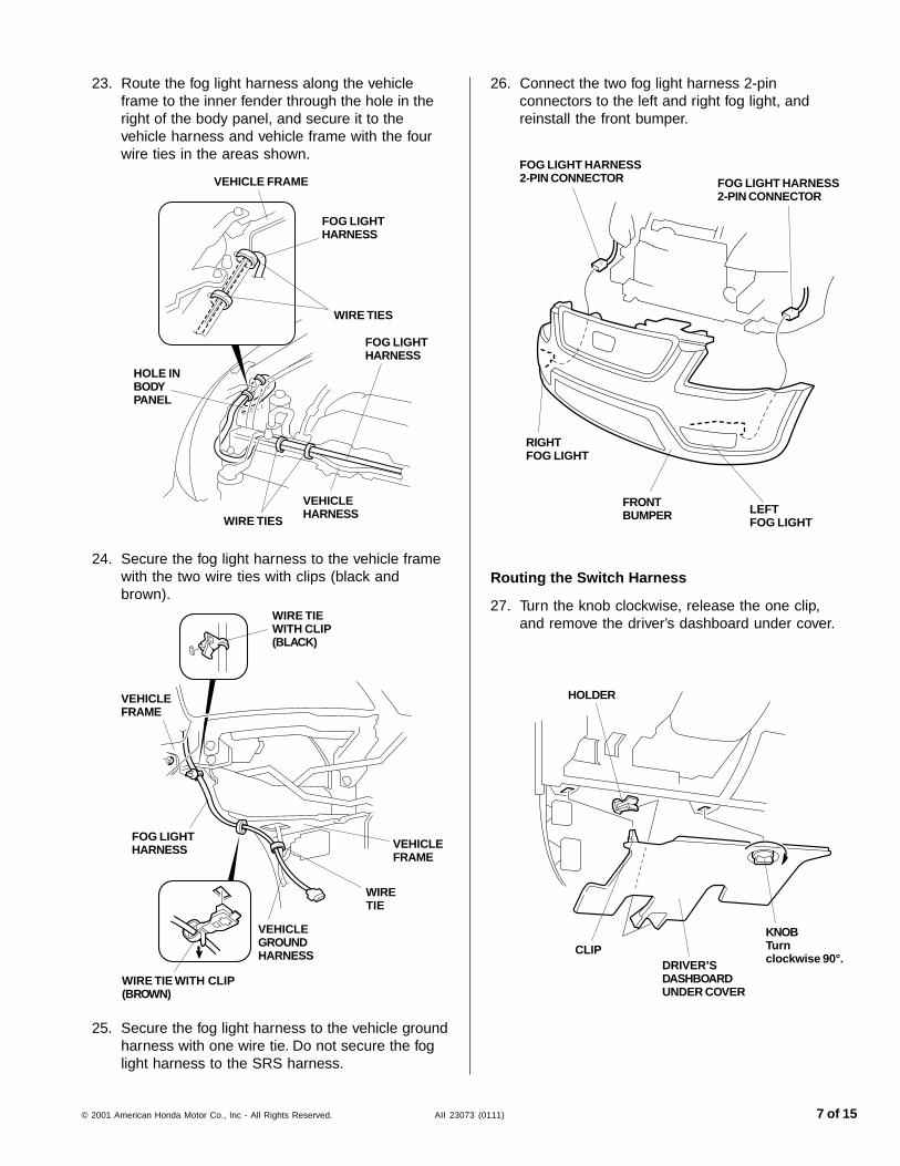
23. Route the fog light harness along the vehicleframe to the inner fender through the hole in theright of the body panel, and secure it to thevehicle harness and vehicle frame with the fourwire ties in the areas shown.
24. Secure the fog light harness to the vehicle framewith the two wire ties with clips (black andbrown).
Routing the Switch Harness
27. Turn the knob clockwise, release the one clip,and remove the driver’s dashboard under cover.
WIRE TIE WITH CLIP(BROWN)
25. Secure the fog light harness to the vehicle groundharness with one wire tie. Do not secure the foglight harness to the SRS harness.
26. Connect the two fog light harness 2-pinconnectors to the left and right fog light, andreinstall the front bumper.
FOG LIGHT HARNESS2-PIN CONNECTOR
LEFTFOG LIGHT
RIGHTFOG LIGHT
FRONTBUMPER
FOG LIGHT HARNESS2-PIN CONNECTOR
DRIVER’SDASHBOARDUNDER COVER
HOLDER
CLIP
KNOBTurnclockwise 90°.
WIRE TIEWITH CLIP(BLACK)
VEHICLEFRAME
FOG LIGHTHARNESS VEHICLE
FRAME
WIRETIE
VEHICLEGROUNDHARNESS
HOLE INBODYPANEL
WIRE TIES
FOG LIGHTHARNESS
VEHICLE FRAME
FOG LIGHTHARNESS
WIRE TIES
VEHICLEHARNESS
8 of 15 AII 23073 (0111) © 2001 American Honda Motor Co., Inc - All Rights Reserved.
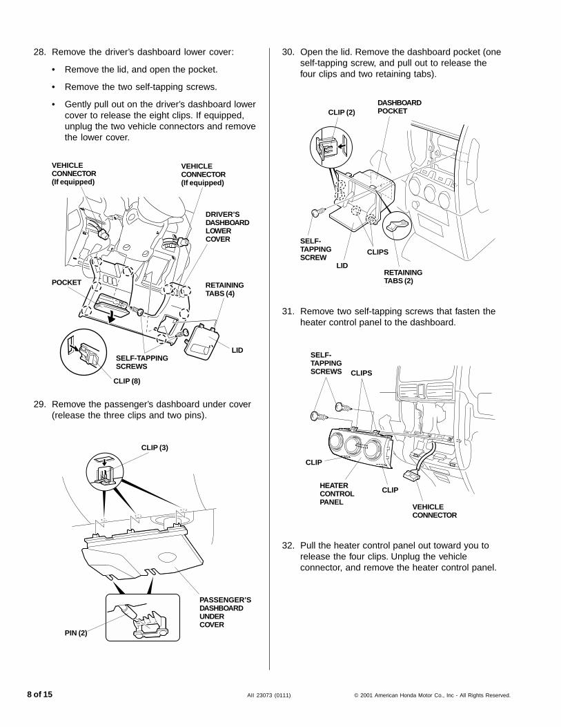
28. Remove the driver’s dashboard lower cover:
• Remove the lid, and open the pocket.
• Remove the two self-tapping screws.
• Gently pull out on the driver’s dashboard lowercover to release the eight clips. If equipped,unplug the two vehicle connectors and removethe lower cover.
VEHICLECONNECTOR(If equipped)
SELF-TAPPINGSCREWS
LID
RETAININGTABS (4)
30. Open the lid. Remove the dashboard pocket (oneself-tapping screw, and pull out to release thefour clips and two retaining tabs).
CLIP (8)
DASHBOARDPOCKET
RETAININGTABS (2)
SELF-TAPPINGSCREW
29. Remove the passenger’s dashboard under cover(release the three clips and two pins).
DRIVER’SDASHBOARDLOWERCOVER
PASSENGER’SDASHBOARDUNDERCOVER
CLIP (3)
PIN (2)
31. Remove two self-tapping screws that fasten theheater control panel to the dashboard.
CLIP (2)
32. Pull the heater control panel out toward you torelease the four clips. Unplug the vehicleconnector, and remove the heater control panel.
CLIP
CLIP
VEHICLECONNECTOR(If equipped)
CLIPS
LID
SELF-TAPPINGSCREWS
HEATERCONTROLPANEL
CLIPS
VEHICLECONNECTOR
© 2001 American Honda Motor Co., Inc - All Rights Reserved. AII 23073 (0111) 9 of 15
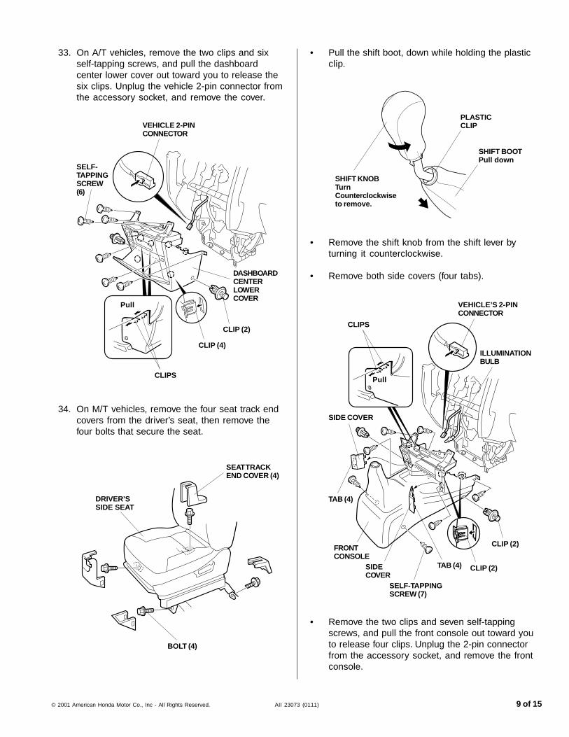
33. On A/T vehicles, remove the two clips and sixself-tapping screws, and pull the dashboardcenter lower cover out toward you to release thesix clips. Unplug the vehicle 2-pin connector fromthe accessory socket, and remove the cover.
34. On M/T vehicles, remove the four seat track endcovers from the driver’s seat, then remove thefour bolts that secure the seat.
DASHBOARDCENTERLOWERCOVER
VEHICLE 2-PINCONNECTOR
SELF-TAPPINGSCREW(6)
CLIP (2)
BOLT (4)
DRIVER’SSIDE SEAT
SEAT TRACKEND COVER (4)
Pull
• Pull the shift boot, down while holding the plasticclip.
• Remove the shift knob from the shift lever byturning it counterclockwise.
• Remove both side covers (four tabs).
• Remove the two clips and seven self-tappingscrews, and pull the front console out toward youto release four clips. Unplug the 2-pin connectorfrom the accessory socket, and remove the frontconsole.
SHIFT KNOBTurnCounterclockwiseto remove.
SHIFT BOOTPull down
PLASTICCLIP
Pull
VEHICLE’S 2-PINCONNECTOR
CLIP (2)
SELF-TAPPINGSCREW (7)
CLIP (2)
TAB (4)SIDECOVER
SIDE COVER
TAB (4)
CLIPS
FRONTCONSOLE
ILLUMINATIONBULB
CLIPS
CLIP (4)
10 of 15 AII 23073 (0111) © 2001 American Honda Motor Co., Inc - All Rights Reserved.
SWITCH HARNESS
1-PINCONNECTORS
OTHER ACCESSORY’SHARNESS
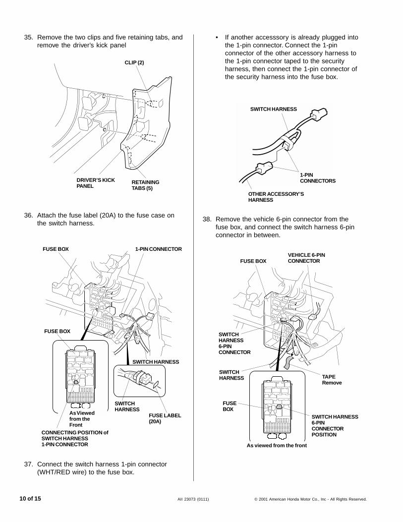
• If another accesssory is already plugged intothe 1-pin connector. Connect the 1-pinconnector of the other accessory harness tothe 1-pin connector taped to the securityharness, then connect the 1-pin connector ofthe security harness into the fuse box.
38. Remove the vehicle 6-pin connector from thefuse box, and connect the switch harness 6-pinconnector in between.
SWITCH HARNESS6-PINCONNECTORPOSITION
VEHICLE 6-PINCONNECTORFUSE BOX
SWITCHHARNESS6-PINCONNECTOR
SWITCHHARNESS
FUSEBOX
As viewed from the front
TAPERemove
1-PIN CONNECTOR
SWITCH HARNESS
FUSE LABEL(20A)
CONNECTING POSITION ofSWITCH HARNESS1-PIN CONNECTOR
FUSE BOX
FUSE BOX
SWITCHHARNESS
As Viewedfrom theFront
35. Remove the two clips and five retaining tabs, andremove the driver’s kick panel
CLIP (2)
DRIVER’S KICKPANEL
36. Attach the fuse label (20A) to the fuse case onthe switch harness.
37. Connect the switch harness 1-pin connector(WHT/RED wire) to the fuse box.
RETAININGTABS (5)
© 2001 American Honda Motor Co., Inc - All Rights Reserved. AII 23073 (0111) 11 of 15
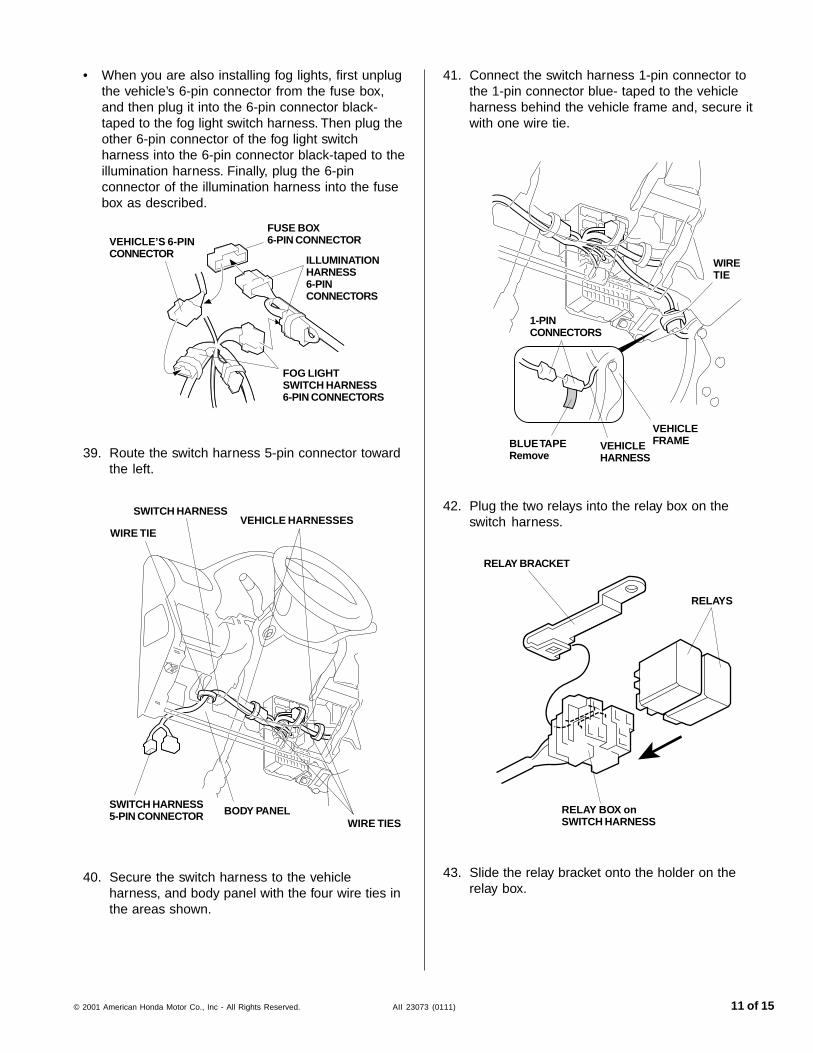
• When you are also installing fog lights, first unplugthe vehicle’s 6-pin connector from the fuse box,and then plug it into the 6-pin connector black-taped to the fog light switch harness. Then plug theother 6-pin connector of the fog light switchharness into the 6-pin connector black-taped to theillumination harness. Finally, plug the 6-pinconnector of the illumination harness into the fusebox as described.
VEHICLE’S 6-PINCONNECTOR
FUSE BOX6-PIN CONNECTOR
ILLUMINATIONHARNESS6-PINCONNECTORS
FOG LIGHTSWITCH HARNESS6-PIN CONNECTORS
39. Route the switch harness 5-pin connector towardthe left.
SWITCH HARNESSVEHICLE HARNESSES
WIRE TIE
SWITCH HARNESS5-PIN CONNECTOR BODY PANEL
WIRE TIES
41. Connect the switch harness 1-pin connector tothe 1-pin connector blue- taped to the vehicleharness behind the vehicle frame and, secure itwith one wire tie.
VEHICLEFRAMEVEHICLE
HARNESSBLUE TAPERemove
1-PINCONNECTORS
WIRETIE
40. Secure the switch harness to the vehicleharness, and body panel with the four wire ties inthe areas shown.
42. Plug the two relays into the relay box on theswitch harness.
RELAYS
RELAY BRACKET
RELAY BOX onSWITCH HARNESS
43. Slide the relay bracket onto the holder on therelay box.
12 of 15 AII 23073 (0111) © 2001 American Honda Motor Co., Inc - All Rights Reserved.
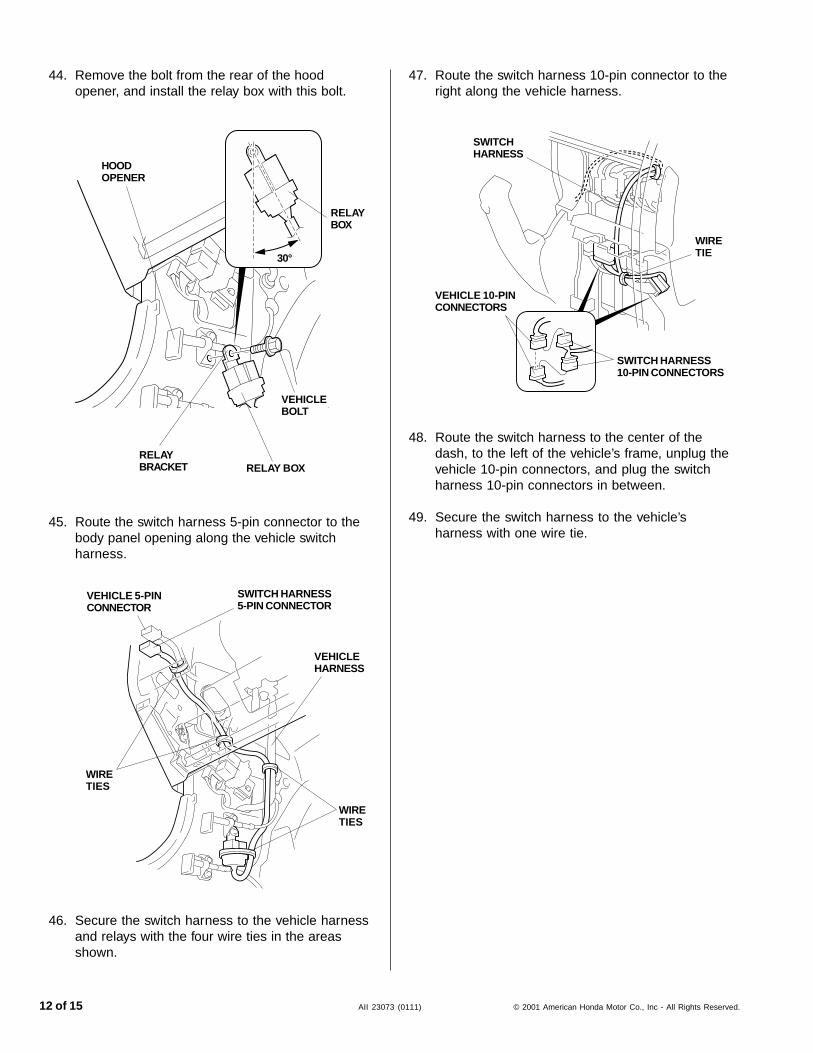
45. Route the switch harness 5-pin connector to thebody panel opening along the vehicle switchharness.
VEHICLE 5-PINCONNECTOR
WIRETIES
WIRETIES
VEHICLEHARNESS
SWITCH HARNESS5-PIN CONNECTOR
47. Route the switch harness 10-pin connector to theright along the vehicle harness.
48. Route the switch harness to the center of thedash, to the left of the vehicle’s frame, unplug thevehicle 10-pin connectors, and plug the switchharness 10-pin connectors in between.
49. Secure the switch harness to the vehicle’sharness with one wire tie.
WIRETIE
SWITCH HARNESS10-PIN CONNECTORS
VEHICLE 10-PINCONNECTORS
SWITCHHARNESS
44. Remove the bolt from the rear of the hoodopener, and install the relay box with this bolt.
HOODOPENER
RELAYBRACKET
VEHICLEBOLT
RELAY BOX
RELAYBOX
30°
46. Secure the switch harness to the vehicle harnessand relays with the four wire ties in the areasshown.
© 2001 American Honda Motor Co., Inc - All Rights Reserved. AII 23073 (0111) 13 of 15
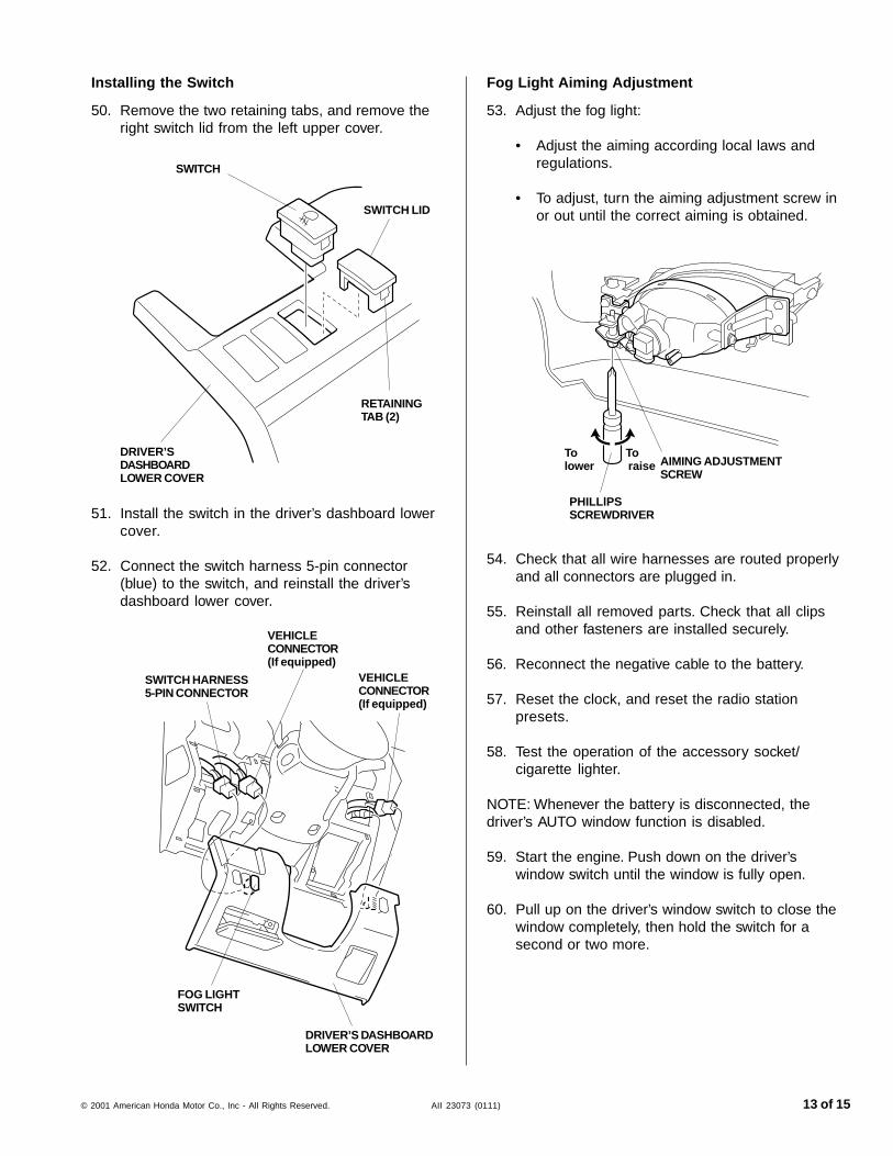
Installing the Switch
50. Remove the two retaining tabs, and remove theright switch lid from the left upper cover.
SWITCH LID
SWITCH
SWITCH HARNESS5-PIN CONNECTOR
FOG LIGHTSWITCH
RETAININGTAB (2)
51. Install the switch in the driver’s dashboard lowercover.
52. Connect the switch harness 5-pin connector(blue) to the switch, and reinstall the driver’sdashboard lower cover.
DRIVER’SDASHBOARDLOWER COVER
DRIVER’S DASHBOARDLOWER COVER
VEHICLECONNECTOR(If equipped)
VEHICLECONNECTOR(If equipped)
54. Check that all wire harnesses are routed properlyand all connectors are plugged in.
55. Reinstall all removed parts. Check that all clipsand other fasteners are installed securely.
56. Reconnect the negative cable to the battery.
57. Reset the clock, and reset the radio stationpresets.
58. Test the operation of the accessory socket/cigarette lighter.
NOTE: Whenever the battery is disconnected, thedriver’s AUTO window function is disabled.
59. Start the engine. Push down on the driver’swindow switch until the window is fully open.
60. Pull up on the driver’s window switch to close thewindow completely, then hold the switch for asecond or two more.
Fog Light Aiming Adjustment
53. Adjust the fog light:
• Adjust the aiming according local laws andregulations.
• To adjust, turn the aiming adjustment screw inor out until the correct aiming is obtained.
Tolower
To raise AIMING ADJUSTMENT
SCREW
PHILLlPSSCREWDRIVER
14 of 15 AII 23073 (0111) © 2001 American Honda Motor Co., Inc - All Rights Reserved.
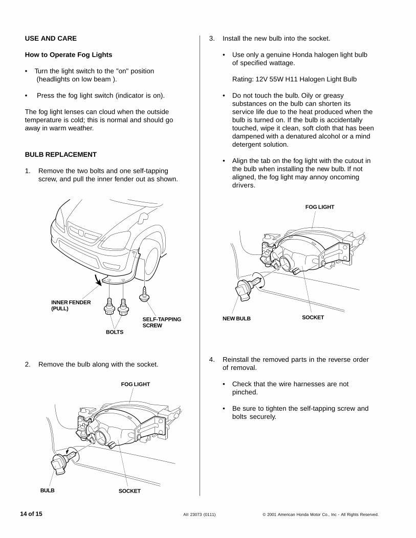
3. Install the new bulb into the socket.
• Use only a genuine Honda halogen light bulbof specified wattage.
Rating: 12V 55W H11 Halogen Light Bulb
• Do not touch the bulb. Oily or greasysubstances on the bulb can shorten itsservice life due to the heat produced when thebulb is turned on. If the bulb is accidentallytouched, wipe it clean, soft cloth that has beendampened with a denatured alcohol or a minddetergent solution.
• Align the tab on the fog light with the cutout inthe bulb when installing the new bulb. If notaligned, the fog light may annoy oncomingdrivers.
4. Reinstall the removed parts in the reverse orderof removal.
• Check that the wire harnesses are notpinched.
• Be sure to tighten the self-tapping screw andbolts securely.
FOG LIGHT
NEW BULB SOCKET
USE AND CARE
How to Operate Fog Lights
• Turn the light switch to the "on" position (headlights on low beam ).
• Press the fog light switch (indicator is on).
The fog light lenses can cloud when the outsidetemperature is cold; this is normal and should goaway in warm weather.
SELF-TAPPINGSCREW
BOLTS
INNER FENDER(PULL)
BULB REPLACEMENT
1. Remove the two bolts and one self-tappingscrew, and pull the inner fender out as shown.
2. Remove the bulb along with the socket.
FOG LIGHT
SOCKETBULB
© 2001 American Honda Motor Co., Inc - All Rights Reserved. AII 23073 (0111) 15 of 15
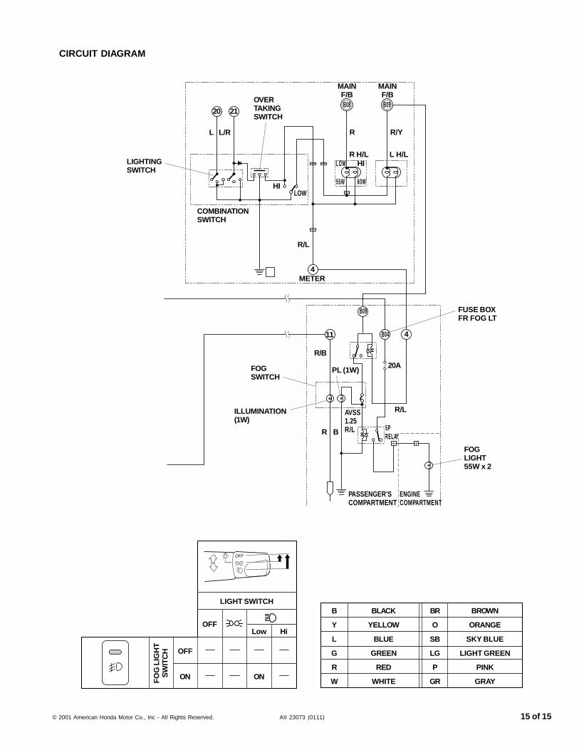
CIRCUIT DIAGRAM
LIGHT SWITCH
OFFLow Hi
OFF
ON ONFO
G L
IGH
TS
WIT
CH
B
Y
L
G
R
W
BR
O
SB
LG
P
GR
BROWN
ORANGE
SKY BLUE
LIGHT GREEN
PINK
GRAY
BLACK
YELLOW
BLUE
GREEN
RED
WHITE
20 21
L L/R
OVERTAKINGSWITCH
LIGHTINGSWITCH
COMBINATIONSWITCH
HILOW
R/L
4METER
MAINF/B
B08
R
MAINF/BB09
R/Y
R H/L L H/LHILOW
60W55W
B09
B04
20A
4
R/L
FUSE BOXFR FOG LT
11
R/B
PL (1W)FOGSWITCH
ILLUMINATION(1W)
R B
AVSS1.25R/L 5P
RELAY
FOGLIGHT55W x 2
PASSENGER’SCOMPARTMENT
ENGINECOMPARTMENT