Embed Size (px)
Citation preview

tWILLIAM T. HUTCHINSON CO.
CATALOG No. 2606
STEEL BLANKSPRECISION GROUNDHIGH SPEED
CUTTING TOOLS • LINEAR MOTION COMPONENTS • MOLD & DIE SUPPLIESINSPECTION & GAGING TOOLS • SHOP TOOLS & SUPPLIES
u f q
DRILL
& REAMER BLANkS
PAGE 2-18
LINE
AR
MOTION COMPONENTS
PAGE 31-34
CUTTING TOOLS
PAGE 19-30
MOLD & DIE SUPPLIES
PAGE 35-40
SHOP TOOLS & SUPPLIES
PAGE 41-63
INSPECTION & GAGING
PAGE 64-75
Please Order From:Clark & Osborne, LLP 317-255-5668 Phone6617 Ferguson Avenue 317-253-4486 FAXIndianapolis, IN 46220 [email protected]

DRIL
L &
REAM
ER B
LANk
S
Page 2
WIRE SIZE HUTCHINSON HSS BLANkS
Typical Analysis of M2 and M42 High Speed SteelC Cr Mo W V Co Hardness
M2 .83 4.0 5.0 6.0 2.0 — R/C 62-64M42 1.10 3.75 9.50 1.50 1.15 8.25 R/C 66-68
CHOICE OF TOLERANCE + .0002– .0000
+ .0000– .0002
OR
CUT COSTS – USE HUTCHINSON HSS BLANkSFOR PUNCHES, EJECTOR PINS AND DOWELS.
QUICK DELIVERYDIRECT FROM OUR PLANTNO ORDER TOO SMALL
Length M2 M42Wire Decimal Overall Net Price Net PriceSize Equivalent Inches Each Each
1 .2280 3 7/8 2.48 3.742 .2210 3 7/8 2.48 3.743 .2130 3 3/4 2.48 3.744 .2090 3 3/4 2.48 3.745 .2055 3 3/4 2.48 3.746 .2040 3 3/4 2.21 3.347 .2010 3 5/8 2.21 3.348 .1990 3 5/8 2.21 3.349 .1960 3 5/8 2.21 3.3410 .1935 3 5/8 2.21 3.3411 .1910 3 1/2 1.94 2.9312 .1890 3 1/2 1.94 2.9313 .1850 3 1/2 1.86 2.8614 .1820 3 1/2 1.86 2.8615 .1800 3 1/2 1.86 2.8616 .1770 3 3/8 1.68 2.5817 .1730 3 3/8 1.68 2.5818 .1695 3 1/4 1.68 2.5819 .1660 3 1/4 1.65 2.4720 .1610 3 1/4 1.65 2.4721 .1590 3 1/4 1.65 2.4722 .1570 3 1/4 1.65 2.4723 .1540 3 1.65 2.4724 .1520 3 1.65 2.4725 .1495 3 1.65 2.4726 .1470 3 1.46 2.2027 .1440 3 1.46 2.2028 .1405 3 1.46 2.2029 .1360 3 1.46 2.2030 .1285 2 3/4 1.46 2.20
Length M2 M42Wire Decimal Overall Net Price Net PriceSize Equivalent Inches Each Each31 .1200 2 3/4 1.38 2.1432 .1160 2 3/4 1.37 2.1033 .1130 2 3/4 1.37 2.1034 .1110 2 3/4 1.37 2.1035 .1100 2 3/4 1.37 2.1036 .1065 2 1/2 1.37 2.0837 .1040 2 1/2 1.37 2.0838 .1015 2 1/2 1.37 2.0839 .0995 2 1/2 1.37 2.0840 .0980 2 1/2 1.37 2.0841 .0960 2 1/2 1.33 2.0042 .0935 2 1/4 1.33 2.0043 .0890 2 1/4 1.33 2.0044 .0860 2 1/4 1.33 2.0045 .0820 2 1/4 1.33 2.0046 .0810 2 1/4 1.33 2.0047 .0785 2 1.30 1.9948 .0760 2 1.30 1.9949 .0730 2 1.30 1.9950 .0700 2 1.30 1.9951 .0670 2 1.30 1.9952 .0635 1 7/8 1.25 1.8453 .0595 1 7/8 1.25 1.8454 .0550 1 7/8 1.25 1.8455 .0520 1 7/8 1.25 1.8456 .0465 1 3/4 1.31 1.9457 .0430 1 3/4 1.31 1.9458 .0420 1 5/8 1.31 1.9459 .0410 1 5/8 1.31 1.9460 .0400 1 5/8 1.31 1.94

DRILL & REAMER BLANkS
Page 3
Length M2 M42Wire Decimal Overall Net Price Net PriceSize Equivalent Inches Each Each
61 .0390 2 1.84 2.5362 .0380 2 1.84 2.5363 .0370 2 1.84 2.5364 .0360 2 1.84 2.5365 .0350 2 1.99 2.7466 .0330 2 1.99 2.7467 .0320 2 1.99 2.74
1/32 .03125 2 1.99 2.7468 .0310 2 1.99 2.7469 .0292 2 2.36 3.2870 .0280 2 2.36 3.2871 .0260 2 2.36 3.2872 .0250 2 2.69 3.7573 .0240 2 2.69 3.7574 .0225 2 2.69 3.7575 .0210 2 2.69 3.7576 .0200 2 3.55 5.0077 .0180 2 3.55 5.0078 .0160 2 3.55 5.00
1/64 .015625 2 3.55 5.0079 .0145 2 3.55 5.0080 .0135 2 3.55 5.00
Length M2 M42Wire Decimal Overall Net Price Net PriceSize Equivalent Inches Each Each
61 .0390 1 1/2 1.50 2.0362 .0380 1 1/2 1.50 2.0363 .0370 1 1/2 1.50 2.0364 .0360 1 1/2 1.50 2.0365 .0350 1 1/2 1.69 2.3266 .0330 1 1/2 1.69 2.3267 .0320 1 1/2 1.69 2.32
1/32 .03125 1 1/2 1.69 2.3268 .0310 1 1/2 1.69 2.3269 .0292 1 1/2 1.83 2.3970 .0280 1 1/2 1.83 2.3971 .0260 1 1/2 1.83 2.3972 .0250 1 1/2 2.14 2.9973 .0240 1 1/2 2.14 2.9974 .0225 1 1/2 2.14 2.9975 .0210 1 1/2 2.14 2.9976 .0200 1 1/2 2.64 3.6877 .0180 1 1/2 2.64 3.6878 .0160 1 1/2 2.64 3.68
1/64 .015625 1 1/2 2.64 3.6879 .0145 1 1/2 2.64 3.6880 .0135 1 1/2 2.64 3.68
WIRE SIZE HUTCHINSON HSS BLANkS
HUTCHINSON HSS BLANkS AREAVAILABLE IN ANY DIAMETER .005" - 1.500"
GROUND TO .0002 TOLERANCELENGTHS UP TO 36" TO SUIT YOUR REQUIREMENTS
All standard size High Speed Steel blanks available for quick delivery from our plantM2 HSS - R/C 62-64 M42 HSS - R/C 66-68
CHOICE OF TOLERANCE + .0002– .0000
+ .0000– .0002
OR
ONE END SOFTBLANkS
ANDBLANkS OF SPECIAL
HARDNESS AVAILABLE
QUANTITY DISCOUNTSThe following discounts apply to orders for blanks ofstandard length and standard diameter only:
100 pieces of one size 5%250 pieces of one size 7 1/2%500 pieces of one size 10%1000 pieces of one size 15%
WHEN ORDERING,SPECIFY:
DIAMETERLENGTH
TOLERANCES
LIMITED SIZES OF M7 AVAILABLE PRICES & AVAILABILITY UPON REQUEST
DRIL
L &
REAM
ER B
LANk
S
Page 4
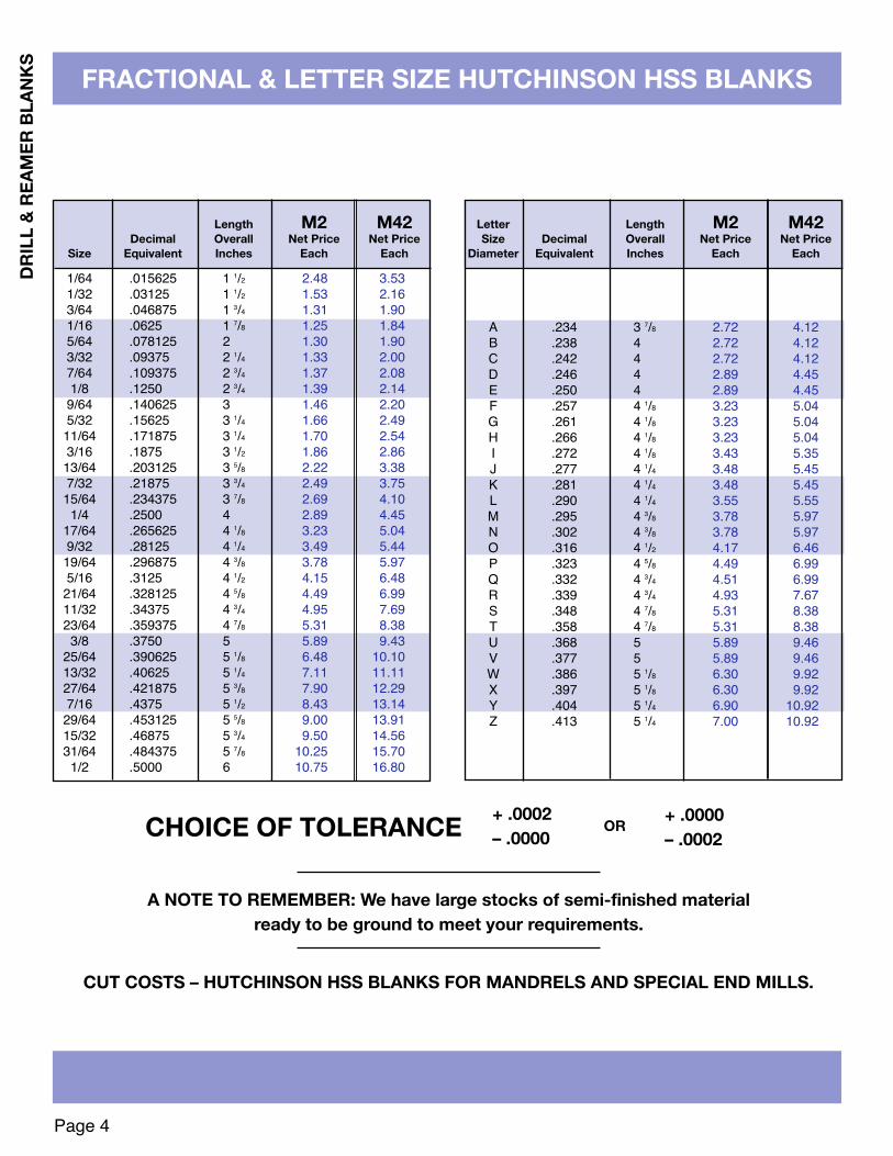
Letter Length M2 M42Size Decimal Overall Net Price Net Price
Diameter Equivalent Inches Each Each
A .234 3 7/8 2.72 4.12B .238 4 2.72 4.12C .242 4 2.72 4.12D .246 4 2.89 4.45E .250 4 2.89 4.45F .257 4 1/8 3.23 5.04G .261 4 1/8 3.23 5.04H .266 4 1/8 3.23 5.04I .272 4 1/8 3.43 5.35J .277 4 1/4 3.48 5.45K .281 4 1/4 3.48 5.45L .290 4 1/4 3.55 5.55M .295 4 3/8 3.78 5.97N .302 4 3/8 3.78 5.97O .316 4 1/2 4.17 6.46P .323 4 5/8 4.49 6.99Q .332 4 3/4 4.51 6.99R .339 4 3/4 4.93 7.67S .348 4 7/8 5.31 8.38T .358 4 7/8 5.31 8.38U .368 5 5.89 9.46V .377 5 5.89 9.46W .386 5 1/8 6.30 9.92X .397 5 1/8 6.30 9.92Y .404 5 1/4 6.90 10.92Z .413 5 1/4 7.00 10.92
FRACTIONAL & LETTER SIZE HUTCHINSON HSS BLANkS
CHOICE OF TOLERANCE + .0002– .0000
+ .0000– .0002
OR
A NOTE TO REMEMBER: We have large stocks of semi-finished materialready to be ground to meet your requirements.
CUT COSTS – HUTCHINSON HSS BLANkS FOR MANDRELS AND SPECIAL END MILLS.
Length M2 M42Decimal Overall Net Price Net Price
Size Equivalent Inches Each Each
1/64 .015625 1 1/2 2.48 3.531/32 .03125 1 1/2 1.53 2.163/64 .046875 1 3/4 1.31 1.901/16 .0625 1 7/8 1.25 1.845/64 .078125 2 1.30 1.903/32 .09375 2 1/4 1.33 2.007/64 .109375 2 3/4 1.37 2.081/8 .1250 2 3/4 1.39 2.14
9/64 .140625 3 1.46 2.205/32 .15625 3 1/4 1.66 2.4911/64 .171875 3 1/4 1.70 2.543/16 .1875 3 1/2 1.86 2.8613/64 .203125 3 5/8 2.22 3.387/32 .21875 3 3/4 2.49 3.7515/64 .234375 3 7/8 2.69 4.101/4 .2500 4 2.89 4.45
17/64 .265625 4 1/8 3.23 5.049/32 .28125 4 1/4 3.49 5.4419/64 .296875 4 3/8 3.78 5.975/16 .3125 4 1/2 4.15 6.4821/64 .328125 4 5/8 4.49 6.9911/32 .34375 4 3/4 4.95 7.6923/64 .359375 4 7/8 5.31 8.383/8 .3750 5 5.89 9.43
25/64 .390625 5 1/8 6.48 10.1013/32 .40625 5 1/4 7.11 11.1127/64 .421875 5 3/8 7.90 12.297/16 .4375 5 1/2 8.43 13.1429/64 .453125 5 5/8 9.00 13.9115/32 .46875 5 3/4 9.50 14.5631/64 .484375 5 7/8 10.25 15.70
1/2 .5000 6 10.75 16.80

DRILL & REAMER BLANkS
Page 5
FRACTIONAL HUTCHINSON HSS BLANkS
CHOICE OF TOLERANCE + .0002– .0000
+ .0000– .0002
OR
Length M2 M42Decimal Overall Net Price Net Price
Size Equivalent Inches Each Each33/64 .515625 6 13.52 20.44
9 22.76 35.0812 30.41 46.90
17/32 .53125 6 13.91 21.009 24.08 37.12
12 31.65 48.7735/64 .546875 6 14.31 21.62
9 24.67 38.0112 32.78 50.50
9/16 .5625 6 15.46 22.919 26.34 40.60
12 34.28 52.8437/64 .578125 6 15.87 23.95
9 27.11 41.8012 36.63 56.20
19/32 .59375 6 16.92 25.549 28.55 44.01
12 38.39 58.9139/64 .609375 6 17.91 26.58
9 30.15 47.4012 39.85 62.45
5/8 .6250 6 18.38 28.319 31.02 48.76
12 41.24 64.6341/64 .640625 6 19.68 29.22
9 34.00 51.5812 44.65 65.18
21/32 .65625 6 20.29 30.139 34.80 52.78
12 45.69 69.1743/64 .671875 6 21.48 31.78
9 35.65 53.9812 47.43 71.81
11/16 .6875 6 21.70 32.259 37.20 56.39
12 49.22 74.5745/64 .703125 6 22.71 33.71
9 38.50 58.3212 51.44 77.95
23/32 .71875 6 23.91 35.509 39.87 60.41
12 53.15 80.4847/64 .734375 6 24.54 36.41
9 40.39 61.1912 54.25 82.16
3/4 .7500 6 25.11 37.319 42.08 63.71
12 54.68 82.79
Length M2 M42Decimal Overall Net Price Net Price
Size Equivalent Inches Each Each49/64 .765625 6 26.73 38.93
9 43.38 64.4912 57.13 84.91
25/32 .78125 6 27.12 40.299 44.80 66.58
12 58.25 86.5851/64 .796875 6 28.57 41.64
9 46.01 68.3812 60.29 89.59
13/16 .8125 6 29.80 43.449 47.24 70.19
12 62.31 92.5653/64 .828125 6 30.82 44.93
9 48.36 71.8512 63.53 94.38
27/32 .84375 6 31.15 46.789 49.48 73.50
12 65.84 97.8155/64 .859375 6 32.58 48.92
9 50.91 75.6012 67.29 99.93
7/8 .8750 6 33.22 50.499 52.61 78.15
12 69.01 102.4957/64 .890625 6 33.74 50.63
9 54.42 80.8412 73.48 109.08
29/32 .90625 6 34.69 52.049 55.55 82.49
12 74.92 111.2659/64 .921875 6 35.49 53.27
9 57.19 84.6412 77.03 114.39
15/16 .9375 6 36.75 55.129 58.40 86.71
12 78.38 116.3761/64 .953125 6 37.51 56.21
9 59.63 88.5212 80.42 119.37
31/32 .96875 6 38.77 60.179 61.25 90.91
12 82.52 122.5363/64 .984375 6 40.91 61.15
9 63.16 93.8112 84.96 126.21
1” 1.0000 6 42.00 61.969 65.05 96.64
12 87.63 130.22

DRIL
L &
REAM
ER B
LANk
S
Page 6
METRIC HUTCHINSON HSS BLANkS
METRIC BLANkS - .35mm - 4.70mm DIAMETERM2 HIGH SPEED STEEL - ROCKWELL “C” 62-64M42 HIGH SPEED STEEL - ROCKWELL “C” 66-68
CHOICE OF TOLERANCE + .0051 mm– .0000
+ .0000– .0051 mm
OR
METRIC BLANkS AVAILABLE .25mm - 35.0mm DIAMETER LENGTHS UP TO 900mm TO SUIT YOUR REQUIREMENTS
Length M2 M42Diameter Overall Net Price Net Price
mm mm Each Each2.10 57 1.53 2.372.15 57 1.53 2.372.20 57 1.53 2.372.25 57 1.53 2.372.30 57 1.53 2.372.35 57 1.53 2.372.40 57 1.58 2.472.45 64 1.58 2.472.50 64 1.58 2.472.60 64 1.58 2.472.70 64 1.58 2.472.75 70 1.58 2.522.80 70 1.58 2.522.90 70 1.58 2.523.00 70 1.63 2.563.10 70 1.63 2.563.20 70 1.66 2.613.25 70 1.66 2.613.30 76 1.66 2.613.40 76 1.66 2.613.50 76 1.66 2.623.60 76 1.66 2.623.70 76 1.66 2.623.75 76 1.75 2.813.80 76 1.75 2.813.90 76 1.75 2.814.00 83 1.75 2.814.10 83 1.75 2.814.20 83 1.75 2.824.25 83 1.79 2.904.30 83 1.79 2.904.40 86 1.79 2.914.50 86 1.79 2.914.60 89 2.05 3.394.70 89 2.05 3.39
Length M2 M42Diameter Overall Net Price Net Price
mm mm Each Each
.35 38 3.31 4.71
.40 38 3.31 4.71
.45 38 3.31 4.71
.50 38 3.31 4.71
.55 38 2.71 3.81
.60 38 2.71 3.81
.65 38 2.71 3.81
.70 38 2.31 3.27
.75 38 2.31 3.27
.80 38 2.07 2.90
.85 38 2.07 2.90
.90 38 2.07 2.90
.95 38 1.91 2.631.00 38 1.91 2.631.05 41 1.75 2.501.10 44 1.75 2.501.15 44 1.75 2.501.20 48 1.75 2.501.25 48 1.75 2.501.30 48 1.67 2.391.35 48 1.67 2.421.40 48 1.67 2.421.45 48 1.67 2.421.50 48 1.67 2.421.55 48 1.67 2.421.60 48 1.67 2.421.65 51 1.67 2.421.70 51 1.67 2.421.75 51 1.52 2.281.80 51 1.52 2.281.85 51 1.52 2.281.90 51 1.52 2.281.95 51 1.52 2.282.00 51 1.52 2.362.05 57 1.53 2.37

DRILL & REAMER BLANkS
Page 7
METRIC HUTCHINSON HSS BLANkS
METRIC BLANkS - 4.75mm - 13.0mm DIAMETERM2 HIGH SPEED STEEL - ROCKWELL “C” 62-64M42 HIGH SPEED STEEL - ROCKWELL “C” 66-68
CHOICE OF TOLERANCE + .0051 mm– .0000
+ .0000– .0051 mm
OR
SPECIALLY EQUIPPED FOR SMALL LOT, HIGH PRECISION CENTERLESS GRINDING
Length M2 M42Diameter Overall Net Price Net Price
mm mm Each Each
7.70 114 4.45 7.577.75 114 4.45 7.577.80 114 4.45 7.577.90 114 4.45 7.578.00 114 4.45 7.578.10 117 4.91 8.188.20 117 4.91 8.188.25 117 4.91 8.188.30 117 4.91 8.188.40 121 4.91 8.188.50 121 5.40 9.028.60 121 5.40 9.028.70 121 5.82 9.718.75 124 5.82 9.818.80 124 5.82 9.818.90 124 5.82 9.819.00 124 5.82 9.819.10 124 5.82 9.819.20 127 6.27 10.759.25 127 6.27 10.759.30 127 6.27 10.759.40 127 6.28 10.769.50 127 6.28 10.769.60 130 6.82 11.729.70 130 6.82 11.729.75 130 6.84 11.749.80 130 6.84 11.749.90 130 6.84 11.74
10.00 130 6.84 11.7410.50 133 7.52 12.9211.00 140 8.69 14.8611.50 142 9.57 15.9012.00 149 10.08 16.7812.50 152 12.15 18.6113.00 152 14.01 23.51
Length M2 M42Diameter Overall Net Price Net Price
mm mm Each Each
4.75 89 2.05 3.394.80 89 2.12 3.474.90 92 2.43 3.955.00 92 2.43 3.955.10 92 2.43 3.955.20 95 2.43 3.965.25 95 2.68 4.355.30 95 2.68 4.355.40 95 2.68 4.355.50 95 2.68 4.355.60 98 2.68 4.355.70 98 2.68 4.355.75 98 2.68 4.355.80 98 2.96 4.795.90 98 2.96 4.796.00 102 2.96 4.796.10 102 2.96 4.796.20 102 3.12 5.126.25 102 3.12 5.126.30 102 3.12 5.126.40 105 3.52 5.896.50 105 3.52 5.896.60 105 3.52 5.896.70 105 3.52 5.896.75 105 3.52 5.896.80 105 3.80 6.336.90 105 3.80 6.337.00 108 3.80 6.337.10 108 3.80 6.337.20 108 3.80 6.377.25 108 3.80 6.377.30 108 3.80 6.377.40 111 4.06 6.807.50 111 4.06 6.807.60 111 4.06 6.80

29/64 .4531 47.94 57.1315/32 .4688 50.01 59.6031/64 .4844 53.97 61.26
1/2 .5000 56.97 63.7617/32 .5312 63.36 161.78
3/8 .3750 34.89 44.1925/64 .3906 37.35 50.9413/32 .4062 39.78 51.1527/64 .4219 42.45 54.097/16 .4375 45.24 56.13
19/64 .2969 24.48 34.285/16 .3125 26.52 34.60
21/64 .3281 28.50 39.2611/32 .3438 30.72 41.6123/64 .3594 32.64 43.82
9/64 .1406 10.50 24.115/32 .1562 11.64 24.2611/64 .1719 12.81 25.443/16 .1875 13.77 25.62
13/64 .2031 15.06 26.69
1/16 .0625 7.17 19.185/64 .0781 7.68 20.713/32 .0938 8.19 20.807/64 .1094 8.64 22.861/8 .1250 9.48 23.97 Wire Decimal Price
Size Equiv. Each61 .0390 20.9062 .0380 20.9063 .0370 20.9064 .0360 20.9065 .0350 21.1866 .0330 21.1867 .0320 21.1868 .0310 21.3869 .0292 21.3870 .0280 21.3871 .0260 21.9672 .0250 21.9673 .0240 21.9674 .0225 22.5375 .0210 22.5376 .0200 22.5377 .0180 22.9678 .0160 22.9679 .0145 23.4780 .0135 23.47
Diameter Decimal PriceInches Equivalent Each17/32 .5312 97.009/16 .5625 111.755/8 .6250 116.50
11/16 .6875 140.7523/32 .7188 148.503/4 .7500 156.50
13/16 .8125 177.007/8 .8750 182.001 1.0000 208.00
7/32 .2188 16.41 26.9115/64 .2344 17.55 28.03
1/4 .2500 19.11 29.2817/64 .2656 20.85 32.429/32 .2812 22.56 32.70
TOLERANCE + .001
36 INCH HARDENED & GROUND HSS LENGTHS
HARDENED GROUNDHIGH SPEEDBLANKS–36”
TOLERANCE .001
WIRE SIZETOLERANCE .0003
HIGH SPEED STEEL DRILL BLANkS
FRACTIONALSIZE
DRILL RODS
DECIMALEQUIVALENT
ANNEALED M2HIGH SPEEDBLANKS–36”
HARDENED, GROUND HSS DRILL BLANkS HAVEA HARDNESS OF R/C 62-64
ALL BLANkS CAN BE CUT TO MEET YOUR REQUIREMENTS.
PRECISION GRINDING AVAILABLE TO A .0002 TOLERANCE
36 INCH HSS LENGTHS
DRIL
L &
REAM
ER B
LANk
S
Page 8
24 INCH HARDENED & GROUNDHSS LENGTHS
-+
-+
Metric Decimal PriceSize Equiv. Each
.50mm .0199 22.53.60 .0236 21.96.70 .0276 21.38.80 .0315 21.38.90 .0354 21.181.00 .0394 20.901.10 .0433 20.901.20 .0472 20.041.30 .0512 20.041.40 .0551 20.041.50 .0591 19.181.60 .0630 19.181.70 .0669 19.181.80 .0709 20.711.90 .0748 20.712.00 .0787 20.712.10 .0827 20.802.20 .866 20.802.30 .0906 20.802.40 .0945 22.862.50 .0984 22.86
METRIC SIZE+.0000TOLERANCE -.0005
9/16 .5625 70.41 171.185/8 .6250 82.77 185.44
11/16 .6875 98.79 209.0223/32 .7188 107.22 215.383/4 .7500 116.04 220.387/8 .8750 155.22 245.741 1.0000 200.34 275.46
1 1/8 1.1250 265.60 370.02

Page 9
DRILL & REAMER BLANkS / CUTTING TOOLS
METRIC BLANKS AVAILABLE AS DRILL BLANKS( )ORREAMER BLANKS ( )
OTHER SETS AVAILABLE TO SUITYOUR NEEDS - CALL FOR PRICINGAND DELIVERY
HSS DRILL BLANk & DRILL SETSConveniently packaged in all steel indexes, sets of general purpose jobber length drills andprecision ground drill or reamer blanks are available for shipment from our plant.Please specify when ordering: Drill set / Drill blank ( ) set / Reamer Blank ( ) set+.0000
-.0002
+.0000-.0051 MM
+.0051-.0000 MM
+.0002-.0000
M2 HSSDRILL BLANK INDEXSET SET ONLY
LETTER SET “A” - “Z”26 PIECES 95.35 121.59 9.45
WIRE SET #1 - #6060 PIECES 81.90 103.89 7.45
WIRE SET #61 - #8020 PIECES 29.00 49.34 4.95
FRACTIONAL SET1/16” - 1/2” x 1/64ths29 PIECES 110.30 136.98 8.65
FRACTIONAL SET1/16” - 1/2” x 1/32nds15 PIECES 59.60 74.25 7.10
M2 HSSDRILL BLANK INDEXSET SET ONLY
1 mm. - 6mm. x 1/2 mm.11 PIECES 19.75 27.73 6.15
1 mm. - 13mm. x 1/2 mm.25 PIECES 99.30 132.43 8.65
1 mm. - 5.9 mm. x .1 mm.50 PIECES 75.45 104.63 9.65
6 mm. - 10 mm. x .1 mm.41 PIECES 178.40 220.79 22.95
METRIC SETS
115 PIECES - COMPLETE IN ONE BOXM2 HSS
INCLUDES: WIRE SET #1 - #60, DRILL BLANK INDEXLETTER SET “A” - “Z”, SET SET ONLY1/16” - 1/2” x 1/64ths 297.15 371.56 34.65
DRIL
L &
REAM
ER B
LANk
S
Page 10
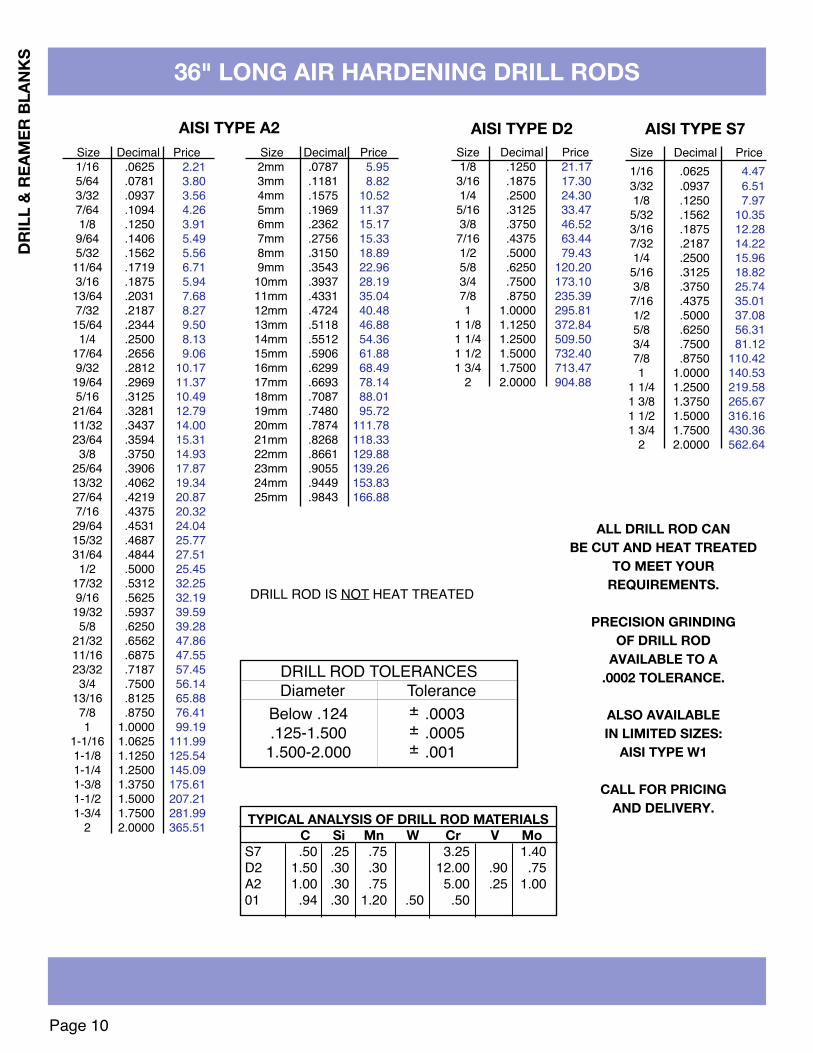
36" LONG AIR HARDENING DRILL RODS
Size Decimal Price1/16 .0625 4.473/32 .0937 6.511/8 .1250 7.97
5/32 .1562 10.353/16 .1875 12.287/32 .2187 14.221/4 .2500 15.96
5/16 .3125 18.823/8 .3750 25.74
7/16 .4375 35.011/2 .5000 37.085/8 .6250 56.313/4 .7500 81.127/8 .8750 110.421 1.0000 140.53
1 1/4 1.2500 219.581 3/8 1.3750 265.671 1/2 1.5000 316.161 3/4 1.7500 430.36
2 2.0000 562.64
ALL DRILL ROD CANBE CUT AND HEAT TREATED
TO MEET YOURREQUIREMENTS.
PRECISION GRINDINGOF DRILL ROD
AVAILABLE TO A.0002 TOLERANCE.
ALSO AVAILABLEIN LIMITED SIZES:
AISI TYPE W1
CALL FOR PRICINGAND DELIVERY.
DRILL ROD IS NOT HEAT TREATED
DRILL ROD TOLERANCESDiameter Tolerance
Below .124 ± .0003.125-1.500 ± .0005
1.500-2.000 ± .001
AISI TYPE S7Size Decimal Price1/8 .1250 21.17
3/16 .1875 17.301/4 .2500 24.30
5/16 .3125 33.473/8 .3750 46.52
7/16 .4375 63.441/2 .5000 79.435/8 .6250 120.203/4 .7500 173.107/8 .8750 235.391 1.0000 295.81
1 1/8 1.1250 372.841 1/4 1.2500 509.501 1/2 1.5000 732.401 3/4 1.7500 713.47
2 2.0000 904.88
AISI TYPE D2Size Decimal Price1/16 .0625 2.215/64 .0781 3.803/32 .0937 3.567/64 .1094 4.261/8 .1250 3.919/64 .1406 5.495/32 .1562 5.5611/64 .1719 6.713/16 .1875 5.9413/64 .2031 7.687/32 .2187 8.2715/64 .2344 9.501/4 .2500 8.13
17/64 .2656 9.069/32 .2812 10.1719/64 .2969 11.375/16 .3125 10.4921/64 .3281 12.7911/32 .3437 14.0023/64 .3594 15.313/8 .3750 14.93
25/64 .3906 17.8713/32 .4062 19.3427/64 .4219 20.877/16 .4375 20.3229/64 .4531 24.0415/32 .4687 25.7731/64 .4844 27.511/2 .5000 25.45
17/32 .5312 32.259/16 .5625 32.1919/32 .5937 39.595/8 .6250 39.28
21/32 .6562 47.8611/16 .6875 47.5523/32 .7187 57.453/4 .7500 56.14
13/16 .8125 65.887/8 .8750 76.411 1.0000 99.19
1-1/16 1.0625 111.991-1/8 1.1250 125.541-1/4 1.2500 145.091-3/8 1.3750 175.611-1/2 1.5000 207.211-3/4 1.7500 281.99
2 2.0000 365.51
Size Decimal Price2mm .0787 5.953mm .1181 8.824mm .1575 10.525mm .1969 11.376mm .2362 15.177mm .2756 15.338mm .3150 18.899mm .3543 22.96
10mm .3937 28.1911mm .4331 35.0412mm .4724 40.4813mm .5118 46.8814mm .5512 54.3615mm .5906 61.8816mm .6299 68.4917mm .6693 78.1418mm .7087 88.0119mm .7480 95.7220mm .7874 111.7821mm .8268 118.3322mm .8661 129.8823mm .9055 139.2624mm .9449 153.8325mm .9843 166.88
AISI TYPE A2
TYPICAL ANALYSIS OF DRILL ROD MATERIALSC Si Mn W Cr V Mo
S7 .50 .25 .75 3.25 1.40D2 1.50 .30 .30 12.00 .90 .75A2 1.00 .30 .75 5.00 .25 1.0001 .94 .30 1.20 .50 .50

Page 11
DRILL & REAMER BLANkS
36" LONG AISI 0-1 OIL HARDENING DRILL RODS
Size Decimal Price Size Decimal Price Size Decimal Price Size Decimal Price60 .039 8.63 37 .103 2.15 14 .180 4.00 K .281 4.9459 .040 8.63 36 .106 2.30 13 .182 4.05 L .290 5.2458 .041 8.63 35 .108 2.38 12 .185 4.21 M .295 5.4457 .042 8.63 34 .110 2.45 11 .188 3.48 N .302 5.7156 .045 8.63 33 .112 2.52 10 .191 3.57 O .316 5.5955 .050 8.63 32 .115 2.69 9 .194 3.73 P .323 5.7854 .055 8.63 31 .120 2.92 8 .197 3.84 Q .332 6.1353 .058 8.63 30 .127 2.43 7 .199 3.87 R .339 6.4152 .063 1.59 29 .134 2.69 6 .201 3.96 S .348 6.7151 .066 1.73 28 .139 2.92 5 .204 4.12 T .358 7.1150 .069 1.87 27 .143 3.09 4 .207 4.19 U .368 7.5349 .072 2.06 26 .146 3.23 3 .212 4.43 V .377 7.7248 .075 2.23 25 .148 3.78 2 .219 4.16 W .386 8.1047 .077 2.38 24 .151 3.43 1 .227 4.46 X .397 8.5846 .079 2.48 23 .153 3.56 A .234 4.73 Y .404 8.8745 .081 2.61 22 .155 3.58 B .238 4.93 Z .413 9.2644 .085 2.81 21 .157 3.03 C .242 5.0643 .088 3.07 20 .161 3.21 D .246 5.2142 .092 3.38 19 .164 3.31 F .257 4.1241 .095 1.83 18 .168 3.48 G .261 4.2540 .097 1.89 17 .172 3.64 H .266 4.4339 .099 2.00 16 .175 3.75 I .272 4.6338 .101 2.13 15 .178 3.90 J .277 4.80
Size Decimal Price Size Decimal Price Size Decimal Price1/16 .0625 $1.45 29/64 .4531 11.14 27/32 .8438 34.265/64 .0781 2.43 15/32 .4688 11.11 55/64 .8594 36.433/32 .0937 1.74 31/64 .4844 12.73 7/8 .8750 35.137/64 .1094 2.43 1/2 .5000 10.78 57/64 .8906 39.151/8 .1250 2.22 33/64 .5156 13.58 29/32 .9063 39.51
9/64 .1406 2.98 17/32 .5313 14.03 59/64 .9219 41.935/32 .1563 2.79 35/64 .5469 15.27 15/16 .9375 42.26
11/64 .1719 3.63 9/16 .5625 15.06 61/64 .9531 44.823/16 .1875 3.21 37/64 .5781 17.08 31/32 .9688 45.14
13/64 .2031 4.05 19/32 .5938 17.57 63/64 .9844 47.797/32 .2188 3.84 39/64 .6094 18.74 1 1.0000 39.67
15/64 .2344 4.76 5/8 .6250 16.66 1-1/16 1.0625 51.631/4 .2500 3.65 41/64 .6406 20.69 1-3/32 1.0938 54.44
17/64 .2656 4.43 21/32 .6563 21.16 1-1/8 1.1250 55.289/32 .2813 4.59 43/64 .6719 22.76 1-3/16 1.1875 64.52
19/64 .2969 5.49 11/16 .6875 22.21 1-1/4 1.2500 64.775/16 .3125 4.59 45/64 .7031 24.93 1-5/16 1.3125 74.79
21/64 .3281 6.00 23/32 .7188 25.38 1-3/8 1.3750 78.3611/32 .3438 6.08 47/64 .7344 27.18 1-7/16 1.4375 89.7623/64 .3594 7.19 3/4 .7500 23.44 1-1/2 1.5000 92.343/8 .3750 6.47 49/64 .7656 28.93 1-9/16 1.5625 99.56
25/64 .3906 8.28 25/32 .7813 29.36 1-5/8 1.6250 113.5013/32 .4062 8.40 51/64 .7969 31.31 1-3/4 1.7500 125.6927/64 .4219 9.64 13/16 .8125 30.31 1-7/8 1.8750 151.147/16 .4375 8.77 53/64 .8281 33.86 2 2.0000 162.83
DRILL ROD IS NOT HEAT TREATED
ALL DRILL ROD CANBE CUT AND HEAT TREATED
TO MEET YOURREQUIREMENTS.
PRECISION GRINDINGOF DRILL ROD
AVAILABLE TO A.0002 TOLERANCE.
ALSO AVAILABLEIN LIMITED SIZES:
AISI TYPE W1
CALL FOR PRICINGAND DELIVERY.
Size Decimal Price2mm .0787 2.983mm .1181 3.454mm .1575 3.775mm .1969 4.736mm .2362 6.507mm .2756 5.848mm .3150 7.029mm .3543 8.45
10mm .3937 10.3411mm .4331 12.7312mm .4724 14.6313mm .5118 16.6614mm .5512 19.3015mm .5906 22.0816mm .6299 24.2817mm .6693 27.8118mm .7087 31.2619mm .7480 33.8920mm .7874 37.5321mm .8268 41.5022mm .8661 45.5123mm .9055 48.3424mm .9449 54.0125mm .9843 58.64
DRILL ROD TOLERANCESDiameter Tolerance
Below .124 ± .0003.125-1.500 ± .00051.500-2.000 ± .001
NUMBER & LETTER SIZES MILLIMETER SIZES
FRACTIONAL SIZES

Page 12
DRIL
L &
REAM
ER B
LANk
S
HUTCHINSON SUPER HIGH ALLOY BLANkS
Length ASP30 T15PM M4PM ASP60 ASP23 CPM10VDiameter Decimal Overall Net Price Net Price Net Price Net Price Net Price Net PriceInches Equivalent Inches Each Each Each Each Each Each
TYPICAL ANALYSIS OF SUPER HIGH ALLOY MATERIALS:C Cr Mo W V Co Hardness
ASP30 1.28 4.2 5.0 6.4 3.1 8.5 R/C 65-67T15PM 1.55 4.0 — 12.0 5.0 5.0 R/C 64-66M4PM 1.35 4.0 4.5 5.75 4.0 — R/C 63-65ASP60 2.30 4.0 7.0 6.5 6.5 10.5 R/C 67-69ASP23 1.28 4.2 5.0 6.4 3.1 — R/C 63-65CPM10V 2.45 5.25 1.3 — 9.75 — R/C 62-64
AVAILABLE IN ANY DIAMETER .0300 - 1.000ADDITIONAL LENGTHS AVAILABLE
TO SUIT YOUR REQUIREMENTS
ASP30 (8.5% COBALT)T15PM (12% TUNGSTEN)ASP60 (10.5% COBALT)M4PM (5.75 TUNGSTEN)ASP23 (AISI M3:2)CPM10V (AISI A11)(9.75% VANADIUM)
ASP30 is an 8.5% cobalt content high-alloyhigh-speed steel man u factured powder-metallur gically. This high per form ance ma terialexhibits good grindability, tough ness, hothardness and wear resistance.
T15PM is a tungsten type high speed steelcontaining high carbon and vanadium for veryhigh hardness and maximum wear resistance,and cobalt for good red hardness. Manu fac -tured powder—metallur gi cally for improvedquality and grindability.
M4PM is designed for high wear resis tance. Itshigh vana dium and carbon content pro vide highresistance to wear in cold work and cuttingappli cations. It exhibits improved performanceworking with abra sive materials. Manu facturedpowder-metallur gically for improved grind a bilityand toughness.
ASP23 An all around steel suitable for cuttingtools such as reamers, taps, milling cutters,broaches, etc. . .Used where cutting conditions demand highwear resistance and superior toughness butwhere demands for hot hardness are notparamount. ASP23 is also suitable for cold workapplications where tools for punching show anadmirable combination of wear resistance andtoughness.
ASP60 is an extremely high alloy high speedsteel. The steel is atomized, compacted andprocessed to required dimensions. The result isan extremely homogeneous steel. ASP 60’shomogeneous structure enhances suchproperties as dimensional stability and shapeduring heat treatment, as well as improvinggrindability and toughness. ASP-60’s method ofmanufacture and composition mean that it canprovide high hot hardness and good wearresistance.
CPM10V(AISI A11) is a unique tool steel madeby a particle metallurgy process. Its high carbonand high vanadium content provides acombination of exceptionally good wearresistance, toughness and strength for bothcold and warm work applications.
+.0002 +.0000CHOICE OF TOLERANCE OR-.0000 -.0002
1/16 .0625 2 1/2 4.99 — 4.30 — 4.21 —3/32 .09375 2 1/2 4.67 — 4.15 — 4.07 —1/8 .1250 2 1/2 3.46 — 3.06 — 3.01 4.69
4 4.72 — 4.17 — 4.09 7.466 6.80 — 6.01 — 5.89 11.20
3/16 .1875 2 1/2 3.81 — 3.55 11.87 3.75 4.994 5.83 — 5.10 18.91 4.96 7.046 9.21 — 8.03 28.97 7.87 11.41
1/4 .2500 2 1/2 5.02 7.33 4.34 11.51 4.25 6.254 7.47 10.92 6.48 17.08 6.33 10.006 11.50 16.79 9.97 26.33 9.76 15.05
5/16 .3125 4 9.66 14.06 8.33 21.86 8.13 13.376 13.57 19.78 11.71 30.67 11.45 20.05
3/8 .3750 4 11.83 16.89 10.04 26.33 9.81 16.286 17.74 25.35 15.05 39.50 14.71 24.40
7/16 .4375 6 22.92 32.77 19.58 — 19.74 —1/2 .5000 4 18.55 26.60 15.66 40.88 15.31 24.18
6 25.89 37.28 21.90 57.01 21.38 36.035/8 .6250 4 31.57 43.49 26.59 69.69 25.98 39.23
6 42.49 60.40 35.86 93.73 35.04 58.843/4 .7500 4 41.89 59.44 35.33 92.41 34.54 53.41
6 57.58 82.00 48.70 126.98 47.56 79.857/8 .8750 6 74.67 106.30 63.17 — — 104.771 1.0000 6 92.64 132.46 78.62 207.83 — 134.58
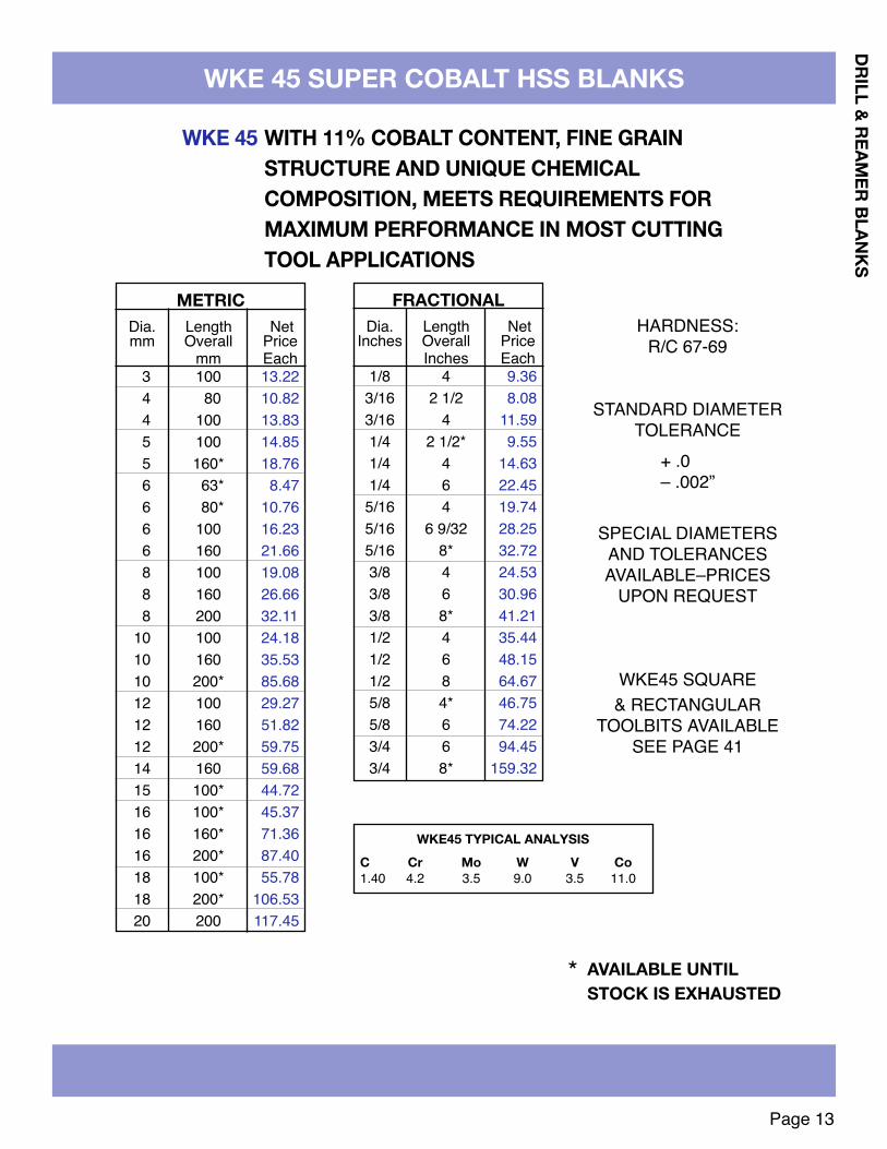
3 100 13.224 80 10.824 100 13.835 100 14.855 160* 18.766 63* 8.476 80* 10.766 100 16.236 160 21.668 100 19.088 160 26.668 200 32.11
10 100 24.1810 160 35.5310 200* 85.6812 100 29.2712 160 51.8212 200* 59.7514 160 59.6815 100* 44.7216 100* 45.3716 160* 71.3616 200* 87.4018 100* 55.7818 200* 106.5320 200 117.45
Page 13
DRILL & REAMER BLANkS
WkE 45 SUPER COBALT HSS BLANkS
METRICDia. Length Netmm Overall Price
mm Each
WkE 45 WITH 11% COBALT CONTENT, FINE GRAINSTRUCTURE AND UNIQUE CHEMICALCOMPOSITION, MEETS REQUIREMENTS FORMAXIMUM PERFORMANCE IN MOST CUTTINGTOOL APPLICATIONS
FRACTIONALDia. Length Net
Inches Overall PriceInches Each
1/8 4 9.363/16 2 1/2 8.083/16 4 11.591/4 2 1/2* 9.551/4 4 14.631/4 6 22.45
5/16 4 19.745/16 6 9/32 28.255/16 8* 32.723/8 4 24.533/8 6 30.963/8 8* 41.211/2 4 35.441/2 6 48.151/2 8 64.675/8 4* 46.755/8 6 74.223/4 6 94.453/4 8* 159.32
WkE45 TYPICAL ANALYSISC Cr Mo W V Co1.40 4.2 3.5 9.0 3.5 11.0
HARDNESS:R/C 67-69
STANDARD DIAMETERTOLERANCE
SPECIAL DIAMETERSAND TOLERANCESAVAILABLE–PRICES
UPON REQUEST
WKE45 SQUARE& RECTANGULAR
TOOLBITS AVAILABLESEE PAGE 41
+ .0– .002”
AVAILABLE UNTILSTOCk IS EXHAUSTED
*

1/81/81/81/81/8 3/163/163/163/163/16 1/41/41/41/41/4 5/165/165/165/16 3/83/83/83/8 7/167/167/167/161/21/21/2
Page 14
ENGR
AVIN
G BL
ANkS ENGRAVING BLANkS
INFORMATION AND PRICING AVAILABLE ON REQUESTALSO AVAILABLE IN BOXED SETS
SINGLE END DOUBLE ENDSolid Tungsten Carbide Blanks with a close sub-micron grain structure, hardness ofRA91.8 and high transverse rupture strength offer superior results when machiningboth ferrous and non ferrous metals as well as plastics, fiberglass and mylar.
1-1/223462
2-1/23462
2-1/2346
2-1/2346
2-1/2346
2-1/2346346
3/83/83/83/83/81/21/21/21/21/21/21/21/21/21/21/21/21/21/21/21/21/21/25/85/85/85/85/85/85/8
5.476.678.35
11.6419.088.559.43
12.3817.2724.4411.2511.9616.2322.7433.2617.6726.9734.7848.6823.1330.8441.4560.8924.4130.8441.4560.8944.9159.0498.24
8.839.44
10.8517.8423.6212.3413.2215.5820.4929.5415.7917.4019.7726.2738.4022.4931.9837.2754.2229.1636.8046.7667.4031.7936.8046.7667.4052.1366.26
107.16
Tolerances: Diameter +.0 Split/Flats +.001 above centerline–.0005 –.0END SHAPES AVAILABLE ON REQUEST - 6PC. MINIMUM PER ITEM
LENGTH OF SINGLE END DOUBLE ENDDIAMETER O.A.L. SPLIT/FLAT PRICE EA. PRICE EACH
SPLIT HALF-ROUNDSolid Tungsten Carbide

3mm 39mm 1.474 51 4.305 51 4.616 51 5.536 64 7.818 64 11.8110 70 18.0610 100 28.0612 76 25.7614 84 38.4916 89 53.4718 100 87.4720 100 100.5725 100 132.09
Page 15
1/16 .0625 3.48 — — 3.23 — — — 8.77 16.073/32 .09375 2.34 3.00 3.19 2.39 — — — 10.20 16.391/8 .1250 1.16 1.93 2.15 3.49 — 4.65 — 10.68 18.125/32 .15625 5.21 2.99 3.75 — — — — 13.57 22.373/16 .1875 2.82 3.44 4.32 5.17 — 6.99 — 19.33 30.811/4 .2500 5.90 6.87 8.51 10.53 13.36 12.41 — 23.24 47.795/16 .3125 — 9.27 11.19 12.26 17.26 19.29 — 34.90 74.673/8 .3750 7.49 12.17 13.61 16.14 20.09 23.63 — 38.13 99.277/16 .4375 — — 17.03 21.51 27.10 28.04 — 42.19 127.001/2 .5000 — 16.40 21.32 25.55 29.81 35.74 40.55 55.45 158.839/16 .5625 — — — — 44.14 — — 73.69 201.025/8 .6250 — — — 40.11 46.78 57.27 73.52 88.23 248.163/4 .7500 — — — 71.37 77.75 76.45 96.21 116.65 285.897/8 .8750 — — 89.67 — — 109.75 — 178.96 389.111 1.0000 — — — — — 126.69 165.95 201.74 361.91
1 1/4 1.2500 — — — — — 256.21 — — —
Dia. Decimal LENGTH11⁄2 2 21⁄2 3 31⁄2 4 5 6 12
DRILL & REAMER BLANkS
CARBIDE DRILL BLANkS
METRIC SIZESDia. Length Price
CENTERLESS GROUND - CUT TO LENGTH
C2 Micrograin Carbide10% Cobalt ContentHardness R/A 91.8
TRS (nominal) 410 KPSIDensity 14.50 Gm/CC
Diameter Tolerance+.0-.0005
Additional grades and tolerances available on applicationAvailable in any diameter 1⁄64"-3" – lengths up to 30"
STYLE STB 1000 & 2000 BLANKS AVAILABLE -SEE PAGES 44 & 45

DRIL
L &
REAM
ER B
LANk
S
Page 16
HARDENED & GROUND TOOL STEEL BLANkS
DECIMAL Net Price Net Price Net Price Net PriceDIAMETER EQUIV. Each Each Each Each
1/16 .0625 $5.71 $5.49 $5.83 $10.055/64 .078125 5.57 5.44 5.59 9.033/32 .09375 5.71 5.58 5.88 8.527/64 .109375 5.23 5.07 5.14 7.801/8 .1250 5.38 5.38 5.69 10.08
5/32 .15625 5.51 5.63 6.02 8.043/16 .1875 5.18 5.40 6.76 11.097/32 .21875 5.74 6.19 7.07 9.051/4 .2500 6.01 6.43 9.71 13.00
9/32 .28125 6.72 7.39 8.42 11.355/16 .3125 6.82 7.68 10.95 15.8311/32 .34375 7.89 9.02 10.64 14.803/8 .3750 8.07 9.17 13.01 18.48
7/16 .4375 10.89 12.97 16.77 25.921/2 .5000 12.18 14.80 16.18 24.659/16 .5625 15.83 19.79 — —5/8 .6250 18.89 22.92 25.16 37.943/4 .7500 24.78 30.44 34.22 52.627/8 .8750 33.30 42.81 46.38 71.371” 1.0000 41.34 50.90 57.79 88.84
AISI O1 AISI A2 AISI S7 AISI D2R/C 60-62 R/C 58-60 R/C 58-60 R/C 60-62
AVAILABLE IN SPECIAL LENGTHS, DIAMETERS,HARDNESS & TOLERANCES TO MEET YOUR REQUIREMENTS
CALL FOR PRICING & DELIVERY
SIX INCH LENGTHSHEAT TREATED & GROUND TO A DIAMETER
TOLERANCE OF +.0000 -.0003
SEE PAGE 10 FORTYPICAL CHEMICAL
ANALYSIS OF THESEMATERIALS
MATERIAL
DRILL & REAMER BLANkS
Page 17
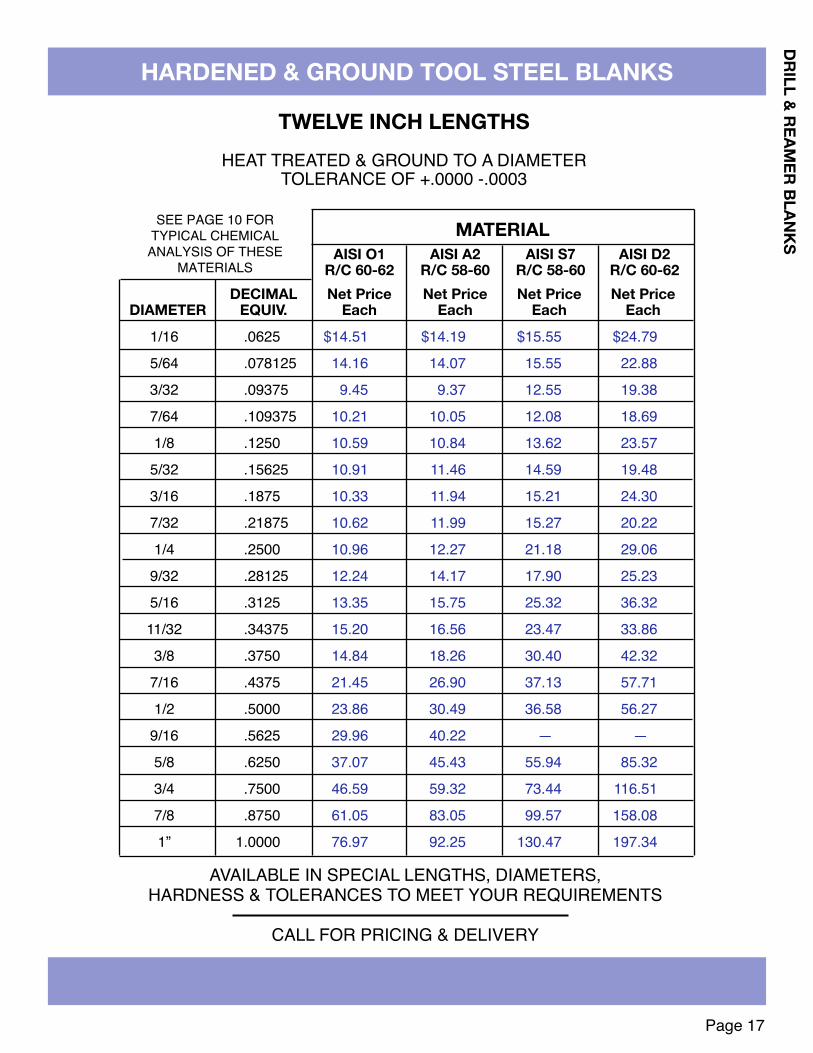
HARDENED & GROUND TOOL STEEL BLANkS
DECIMAL Net Price Net Price Net Price Net PriceDIAMETER EQUIV. Each Each Each Each
1/16 .0625 $14.51 $14.19 $15.55 $24.795/64 .078125 14.16 14.07 15.55 22.883/32 .09375 9.45 9.37 12.55 19.387/64 .109375 10.21 10.05 12.08 18.691/8 .1250 10.59 10.84 13.62 23.575/32 .15625 10.91 11.46 14.59 19.483/16 .1875 10.33 11.94 15.21 24.307/32 .21875 10.62 11.99 15.27 20.221/4 .2500 10.96 12.27 21.18 29.069/32 .28125 12.24 14.17 17.90 25.235/16 .3125 13.35 15.75 25.32 36.3211/32 .34375 15.20 16.56 23.47 33.863/8 .3750 14.84 18.26 30.40 42.327/16 .4375 21.45 26.90 37.13 57.711/2 .5000 23.86 30.49 36.58 56.279/16 .5625 29.96 40.22 — —5/8 .6250 37.07 45.43 55.94 85.323/4 .7500 46.59 59.32 73.44 116.517/8 .8750 61.05 83.05 99.57 158.081” 1.0000 76.97 92.25 130.47 197.34
AISI O1 AISI A2 AISI S7 AISI D2R/C 60-62 R/C 58-60 R/C 58-60 R/C 60-62
AVAILABLE IN SPECIAL LENGTHS, DIAMETERS,HARDNESS & TOLERANCES TO MEET YOUR REQUIREMENTS
CALL FOR PRICING & DELIVERY
TWELVE INCH LENGTHSHEAT TREATED & GROUND TO A DIAMETER
TOLERANCE OF +.0000 -.0003
SEE PAGE 10 FORTYPICAL CHEMICAL
ANALYSIS OF THESEMATERIALS
MATERIAL

DRIL
L &
REAM
ER B
LANk
S
Page 18
HARDENED & GROUND 440C STAINLESS STEEL BLANkS
DECIMAL Net Price Net PriceDIAMETER EQUIV. Each Each
1/16 .0625 $16.42 $35.385/64 .078125 14.42 31.383/32 .09375 12.42 27.387/64 .109375 10.42 23.381/8 .1250 13.21 29.11
5/32 .15625 14.44 30.943/16 .1875 15.03 30.097/32 .21875 11.03 22.091/4 .2500 19.82 41.22
9/32 .28125 15.82 33.225/16 .3125 17.96 36.1611/32 .34375 13.96 28.163/8 .3750 19.87 41.67
7/16 .4375 22.18 46.681/2 .5000 25.43 50.10
9/16 .5625 34.17 71.245/8 .6250 37.00 76.513/4 .7500 43.92 87.507/8 .8750 56.37 111.721” 1.0000 63.36 125.71
6” LONG 12” LONG
AVAILABLE IN SPECIAL LENGTHS, DIAMETERS,HARDNESS & TOLERANCES TO MEET YOUR REQUIREMENTS
CALL FOR PRICING & DELIVERY
SIX & TWELVE INCH LENGTHSHEAT TREATED TO R/C 58-60 & GROUND
TO A DIAMETER TOLERANCE OF +.0000 -.0003
HEAT TREATED 440C IS ONE OF THE HARDEST STAINLESS STEELS.IT IS MAGNETIC AND HAS GOOD WEAR RESISTANCE DUE TO HIGH CARBON CONTENT

Page 19
Fractional Decimal General Heavy Fast Slow HalfCobaltSize Equivalent Purpose Duty Spiral Spiral Round118° Point 135° Split Point 135° Split Point 118° Point 118° Point 118° Point
FRACTIONAL HSS DRILLS
1/641/323/641/165/643/327/641/89/645/3211/643/1613/647/3215/64
1/417/649/3219/645/1621/6411/3223/643/8
25/6413/3227/647/1629/6415/3231/641/2
.015625
.03125
.046875
.0625
.078125
.09375
.109375
.1250
.140625
.15625
.171875
.1875
.203125
.21875
.234375
.2500
.265625
.28125
.296875
.3125
.328125
.34375
.359375
.3750
.390625
.40625
.421875
.4375
.453125
.46875
.484375
.5000
2.161.321.321.291.291.181.241.211.331.361.481.651.822.012.182.302.792.883.343.694.114.555.145.236.016.156.847.148.018.468.938.86
———1.381.381.381.461.461.601.621.751.972.152.392.622.753.313.403.954.354.865.396.116.227.147.338.148.479.47
10.0410.5310.56
*3.77*3.09*2.222.032.032.032.142.592.622.933.093.444.154.554.845.115.846.137.497.988.799.64
11.1610.9912.6213.1414.5514.8517.9118.2418.8118.51
2.172.391.871.851.871.871.881.811.881.962.362.633.013.293.723.544.794.785.545.676.607.008.748.44
10.159.85
11.7811.5612.6813.0614.2813.79
3.262.722.582.462.462.462.462.382.382.853.203.353.784.434.854.855.846.467.177.908.349.36
11.1711.1712.3312.8314.4814.8816.9118.2519.0619.06
5.894.468.428.688.688.689.069.189.91
10.0810.5611.4312.6413.5614.5319.9222.4725.0727.6330.2833.1736.1539.1642.1345.5849.0252.4655.8959.6163.3367.0570.75
ALSO AVAILABLE : • LETTER SIZES • DECIMAL SIZES• PARABOLIC FLUTE • METRIC SIZES• STRAIGHT FLUTE • TAPER LENGTHS• CARBIDE TIPPED • TYPE M• TAPER SHANkS • AUTOMOTIVE• SUPERFLUTE • BRITE OR BLACk FINISH• TYPE A • TYPE B• TYPE C
CALL FOR PRICING AND DELIVERYNO MINIMUM ORDER
NO PACkAGE QUANTITY
CUTTING TOOLS
* NOT SPLIT POINT
Page 20
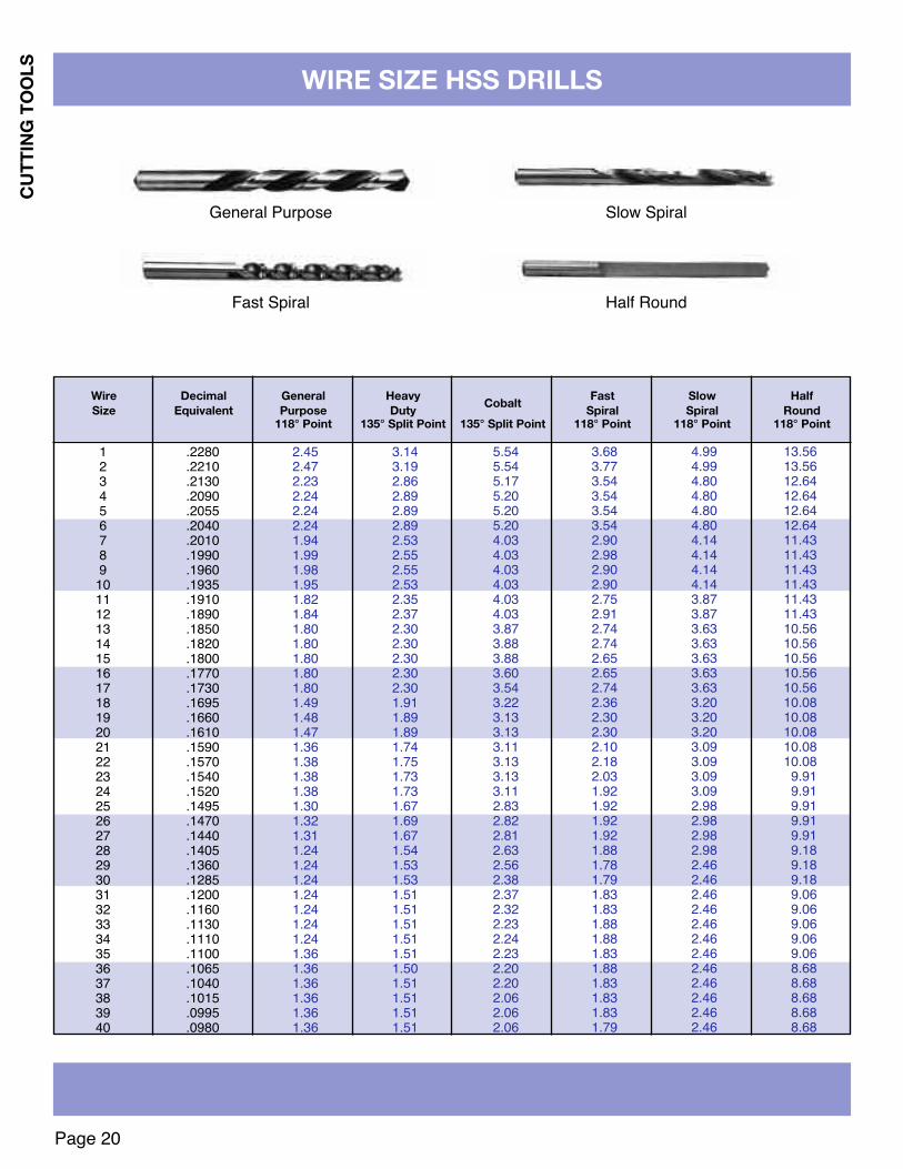
WIRE SIZE HSS DRILLS
CUTT
ING
TOOL
S
Wire Decimal General Heavy Fast Slow HalfCobaltSize Equivalent Purpose Duty Spiral Spiral Round118° Point 135° Split Point 135° Split Point 118° Point 118° Point 118° Point
12345678910111213141516171819202122232425262728293031323334353637383940
.2280
.2210
.2130
.2090
.2055
.2040
.2010
.1990
.1960
.1935
.1910
.1890
.1850
.1820
.1800
.1770
.1730
.1695
.1660
.1610
.1590
.1570
.1540
.1520
.1495
.1470
.1440
.1405
.1360
.1285
.1200
.1160
.1130
.1110
.1100
.1065
.1040
.1015
.0995
.0980
2.452.472.232.242.242.241.941.991.981.951.821.841.801.801.801.801.801.491.481.471.361.381.381.381.301.321.311.241.241.241.241.241.241.241.361.361.361.361.361.36
3.143.192.862.892.892.892.532.552.552.532.352.372.302.302.302.302.301.911.891.891.741.751.731.731.671.691.671.541.531.531.511.511.511.511.511.501.511.511.511.51
5.545.545.175.205.205.204.034.034.034.034.034.033.873.883.883.603.543.223.133.133.113.133.133.112.832.822.812.632.562.382.372.322.232.242.232.202.202.062.062.06
3.683.773.543.543.543.542.902.982.902.902.752.912.742.742.652.652.742.362.302.302.102.182.031.921.921.921.921.881.781.791.831.831.881.881.831.881.831.831.831.79
4.994.994.804.804.804.804.144.144.144.143.873.873.633.633.633.633.633.203.203.203.093.093.093.092.982.982.982.982.462.462.462.462.462.462.462.462.462.462.462.46
13.5613.5612.6412.6412.6412.6411.4311.4311.4311.4311.4311.4310.5610.5610.5610.5610.5610.0810.0810.0810.0810.08
9.919.919.919.919.919.189.189.189.069.069.069.069.068.688.688.688.688.68
General Purpose Slow Spiral
Fast Spiral Half Round
Page 21
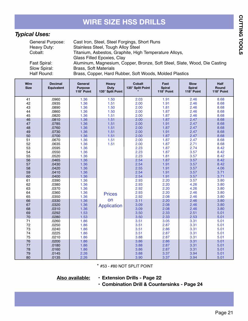
WIRE SIZE HSS DRILLS
CUTTING TOOLS
Wire Decimal General Heavy Cobalt Fast Slow HalfSize Equivalent Purpose Duty 135° Split Point Spiral Spiral Round
118° Point 135° Split Point * 118° Point 118° Point 118° Point
41424344454647484950515253545556575859606162636465666768697071727374757677787980
.0960
.0935
.0890
.0860
.0820
.0810
.0785
.0760
.0730
.0700
.0670
.0635
.0595
.0550
.0520
.0465
.0430
.0420
.0410
.0400
.0390
.0380
.0370
.0360
.0350
.0330
.0320
.0310
.0292
.0280
.0260
.0250
.0240
.0225
.0210
.0200
.0180
.0160
.0145
.0135
1.361.361.361.361.361.361.361.361.361.361.361.361.361.361.361.361.361.361.361.361.361.361.361.361.361.361.361.361.531.531.861.861.861.861.861.861.861.862.262.26
1.501.511.501.501.511.511.511.511.511.511.511.51
2.032.002.002.002.002.002.002.002.002.002.002.002.232.232.232.542.542.552.542.542.932.932.922.932.923.113.093.093.503.503.513.513.513.513.883.863.883.863.883.90
1.911.911.811.871.871.871.911.871.911.871.871.871.871.871.811.871.911.911.911.912.202.202.202.202.082.202.082.082.332.333.052.872.862.872.872.862.872.873.373.37
2.462.462.462.462.462.472.472.472.472.472.472.712.743.573.573.573.573.573.573.573.574.264.262.462.462.462.462.462.512.533.313.313.313.313.313.313.313.313.943.94
8.688.688.688.688.688.688.688.688.688.688.688.688.428.428.428.428.424.063.713.713.803.803.803.803.803.803.803.805.015.015.015.015.015.015.015.015.015.015.015.01
Also available: • Extension Drills - Page 22• Combination Drill & Countersinks - Page 24
Typical Uses:General Purpose: Cast Iron, Steel, Steel Forgings, Short RunsHeavy Duty: Stainless Steel, Tough Alloy SteelCobalt: Titanium, Asbestos, Graphite, High Temperature Alloys,
Glass Filled Epoxies, ClayFast Spiral: Aluminum, Magnesium, Copper, Bronze, Soft Steel, Slate, Wood, Die CastingSlow Spiral: Brass, Soft MaterialsHalf Round: Brass, Copper, Hard Rubber, Soft Woods, Molded Plastics
Priceson
Application
* #53 - #80 NOT SPLIT POINT

1/8 .1250 3.66 10.05 2.35 10.13 18.25 40.419/64 .140625 3.66 10.05 2.45 9.91 19.82 25.925/32 .15625 3.66 10.05 2.63 11.16 19.82 40.4111/64 .171875 4.02 11.13 2.72 11.40 20.65 25.923/16 .1875 4.02 11.13 2.92 11.47 20.65 41.99
9/32 .28125 12.29 17.28 4.42 13.44 24.14 35.1519/64 .296875 14.44 19.59 4.80 13.54 24.85 35.155/16 .3125 15.67 22.02 5.36 13.78 24.85 44.3921/64 .328125 17.01 23.05 5.55 17.79 25.90 37.2511/32 .34375 16.83 23.75 6.03 14.55 25.90 37.25
7/16 .4375 23.32 32.08 8.10 17.76 31.60 55.6029/64 .453125 25.56 33.98 8.49 20.33 34.74 49.9715/32 .46875 26.51 36.49 8.95 19.87 34.74 49.9731/64 .484375 27.49 36.49 9.32 27.25 35.43 52.071/2 .5000 27.97 38.53 9.62 19.94 35.43 66.29
23/64 .359375 18.90 25.58 6.12 16.43 26.57 37.253/8 .3750 19.25 27.05 6.40 14.80 26.57 47.60
25/64 .390625 21.48 28.53 6.79 18.67 29.85 40.5313/32 .40625 20.72 28.53 7.16 16.79 29.85 40.5327/64 .421875 23.05 30.65 7.55 23.58 31.60 43.74
Size Decimal 6” Aircraft 12” Aircraft 12” 8” 12” 18”Equivalent Extension Extension Extended Longboy Longboy Longboy
135° Split Point 135° Split Point 135° Split Point 118° Point 118° Point 118° Point
EXTENSION DRILLS & LONGBOYS
• Aircraft extension drills are one-piece extra-long shafts with the same flute length as jobber length drills.• 12” extended drills are an economical alternative to aircraft extensions with HSS shafts welded to jobber
length drills.• Longboy drills are fluted over a much longer length for certain deep hole drilling applications.• Additional lengths up to 24” available - Call for price and delivery
1/16 .0625 4.08 12.79 2.72 — 20.47 —5/64 .078125 4.08 12.79 2.72 — 17.86 —3/32 .09375 3.66 12.79 2.34 12.88 23.89 —7/64 .109375 3.66 10.05 2.53 10.87 15.61 —
13/64 .203125 4.88 12.79 3.10 12.46 24.14 31.747/32 .21875 4.88 12.79 3.29 12.48 24.14 31.7415/64 .234375 5.31 13.75 3.48 12.38 24.14 31.74
1/4 .2500 5.31 13.75 3.78 12.80 24.14 42.0617/64 .265625 11.84 16.35 4.23 11.87 24.14 35.15
Page 22
CUTT
ING
TOOL
S

Page 23
DOUBLE END END MILLS
1/32 3/64 16.60 24.50 17.60 3/32 18.70 25.60 18.603/64 1/16 16.60 24.50 17.60 9/64 18.70 25.60 18.601/16 3/32 15.60 22.10 16.00 3/16 16.50 23.40 16.905/64 1/8 15.60 22.10 16.00 15/64 16.50 23.40 20.193/32 9/64 15.60 22.10 16.00 9/32 16.50 23.40 16.907/64 5/32 15.60 22.10 16.00 21/64 16.50 23.40 20.191/8 3/16 15.60 22.10 16.00 3/8 16.50 23.40 16.909/64 7/32 17.50 24.80 17.10 13/32 17.60 24.50 20.705/32 15/64 17.50 24.80 17.10 7/16 17.60 24.50 17.9011/64 1/4 17.50 24.80 17.10 1/2 17.60 24.50 21.563/16 9/32 17.50 24.80 17.10 1/2 17.60 24.50 17.90
Diameterof Cutter
Length of Cut
Length of Cut2 Flute 4 Flute2 Flute Ball 2 Flute 4 Flute2 Flute Ball
3/16 Shank, Double End Cobalt
Stub (2” Long) Standard (2-1/4” Long)
• Single End Carbide• Ball End Carbide
ALSO AVAILABLE:
• 4 Flute Ball• 3 Flute
• 2 Flute Single End• 4 Flute Single End
• Decimal Sizes .006 - .187• Metric Sizes
Diameter Shank Length Length 2-FLUTE 4-FLUTEof Cut Diameter of Cut Overal1/32 1/8 1/16 1-1/2 17.01 17.893/64 1/8 1/16 1-1/2 17.01 17.891/16 1/8 1/8 1-1/2 16.20 17.025/64 1/8 1/8 1-1/2 16.20 17.023/32 1/8 3/16 1-1/2 16.20 17.027/64 1/8 1/4 1-1/2 16.20 17.021/8 1/8 1/4 1-1/2 16.20 17.029/64 3/16 5/16 2 21.99 23.065/32 3/16 5/16 2 21.99 22.5011/64 3/16 3/8 2 21.99 22.503/16 3/16 3/8 2 21.99 22.507/32 1/4 1/2 2-1/2 27.27 28.601/4 1/4 1/2 2-1/2 27.27 28.605/16 5/16 1/2 2-1/2 37.67 39.573/8 5/16 1/2 2-1/2 40.28 42.28
Double End Carbide End Mills, Stub Length
CUTTING TOOLS

Page 24
CUTT
ING
TOOL
S
COMBINATION DRILL & COUNTERSINkS
Countersink Diameter Diameter Length Length 60˚ R.H. 82˚ Angle 90˚ AngleSize of of of Overall Price R.H. R.H
Number Body Drill Drill Inches Each Price Each Price Each00000 1/8 .010 .010 11⁄4 8.80 — 33.980000 1/8 .015 .015 11⁄4 8.08 — 33.98000 1/8 .020 .020 11⁄4 7.66 — 21.7000 1/8 .025 .025 11⁄4 7.66 21.70 21.700 1/8 1/32 1/32 11⁄4 7.66 21.70 21.701 1/8 3/64 3/64 11⁄4 5.18 9.73 9.732 3/16 5/64 5/64 17⁄8 5.42 9.96 9.963 1/4 7/64 7/64 2 5.64 10.31 10.314 5/16 1/8 1/8 21⁄8 5.83 10.70 10.7041⁄2 3/8 9/64 9/64 21⁄2 8.97 14.67 14.675 7/16 3/16 3/16 23⁄4 9.19 16.32 16.326 1/2 7/32 7/32 3 13.87 24.72 24.727 5/8 1/4 1/4 31⁄4 20.02 34.96 34.968 3/4 5/16 5/16 31⁄2 27.85 49.04 49.049 7/8 11/32 11/32 35⁄8 52.30 — —
10 1” 3/8 3/8 33⁄4 68.66 — —
Countersink Diameter Diameter Length Diameter Length HSS RH M42 RH T15 RHSize of of of of Bell Overall Price Price Price
Number Body Drill Drill Inches Inches Each Each Each11 1/8 3/64 3/64 .100 11⁄4 6.16 16.06 21.5212 3/16 1/16 1/16 .150 17⁄8 6.45 16.47 22.0313 1/4 3/32 3/32 .200 2 6.54 16.92 22.6314 5/16 7/64 7/64 .250 21⁄8 6.75 17.48 23.1115 7/16 5/32 5/32 .350 23⁄4 10.28 27.88 36.5316 1/2 3/16 3/16 .400 3 15.81 43.10 55.6317 5/8 7/32 7/32 .500 31⁄4 23.49 64.14 83.5118 3/4 1/4 1/4 .600 31⁄2 31.47 89.50 119.00
PLAIN TYPE COUNTERSINkS
Countersink Diameter Diameter Length 3” 4” 5” 6”Size of of of Price Price Price Price
Number Body Drill Drill Each Each Each Each1 1/8 3/64 3/64 13.59 14.18 19.72 25.792 3/16 5/64 5/64 — 15.54 19.89 25.903 1/4 7/64 7/64 — 16.35 21.54 26.144 5/16 1/8 1/8 — 18.14 23.16 26.77
4 1/2 3/8 9/64 9/64 — 20.39 24.10 29.045 7/16 3/16 3/16 — 23.82 27.59 30.986 1/2 7/32 7/32 — — 29.64 35.827 5/8 1/4 1/4 — — — 66.068 3/4 5/16 5/16 — — — 71.42
LONGBOY COUNTERSINkS (HSS 60˚ Angle)FOR LONG REACH APPLICATIONS - 3, 4, 5 & 6" OVERALL
BELL TYPE COUNTERSINkS

Page 25
Tool C/L Angles Body Shank Shank O/A HSSNo. Available Dia. Dia. Length Length Price
1/8-SF 1/8 1/8 - 11⁄2 6.863/16-SF 3/16 3/16 - 11⁄2 7.331/4-SF 1/4 1/4 - 2 7.635/16-SF 5/16 1/4 7/8 13⁄4 8.963/8-SF 3/8 1/4 7/8 13⁄4 10.371/2-SF 1/2 1/4 11⁄8 21⁄8 13.33
5/8-SF 5/8 3/8 11⁄8 23⁄8 18.943/4-SF 3/4 1/2 15⁄16 211⁄16 25.371-SF 1 1/2 15⁄16 213⁄16 38.91
11⁄4-SF 11⁄4 3/4 15⁄8 33⁄8 62.4411⁄2-SF 11⁄2 3/4 15⁄8 31⁄2 85.7613⁄4-SF 13⁄4 1 21⁄8 41⁄4 116.10
2-SF 2 1 21⁄8 43⁄8 147.0021⁄2-SF 21⁄2 1 21⁄8 43⁄4 248.873-SF 3 1 21⁄8 5 373.92
Tool C/L Angles O/A PriceNo. Available Diameter Length Each
CK-1/8-W-DE 1/8 11⁄2 17.61CK-3/16-W-DE 3/16 2 25.37CK-1/4-W-DE 1/4 2 34.59CK-3/8-W-DE 3/8 21⁄2 77.53CK-1/2-W-DE 1/2 3 107.44CK-5/8-W-DE 5/8 31⁄2 89.20
SINGLE & SIX FLUTE COUNTERSINkS
30°41°45°50°
AND60°
30°41°45°50°
AND60°
SIX FLUTECOUNTERSINkS
DOUBLE END Six Flute Countersinks
DESIGN - Hutchinson Countersinks are designed to take heavy cuts and produce exceptionally smooth seats.SHEAR-CUT TEETH - Cutting teeth are arranged to give a shearing cut, eliminating “chatter” possibility.TRUNCATED END-DIMENSIONS- Diameter at small end of 30° countersinks is approximately one third of the bodydiameter; of 41° and 45° countersinks it is about one-fifth, and of 60° countersinks it is about one-sixth.
HIGH SPEED STEEL
HIGH SPEED STEEL
CARBIDE
CARBIDE
30°41°45°50°60°
CUTTING TOOLS
30°41°45°50°60°
SINGLE FLUTECOUNTERSINkS
30°41°45°50°
AND60°
Tool C/L Angles O/A PriceNo. Available Diameter Length Each
CK-1/8-DE 1/8 11⁄2 12.86CK-3/16-DE 3/16 2 14.01CK-1/4-DE 1/4 2 14.36CK-3/8-DE 3/8 21⁄2 24.26CK-1/2-DE 1/2 3 35.19CK-5/8-DE 5/8 31⁄2 52.76
Tool C/L Angles Body Shank Shank O/A PriceNo. Available Dia. Dia. Length Length Each
CK-1/8 1/8 1/8 - 11⁄2 7.54CK-3/16 3/16 3/16 - 11⁄2 8.10CK-1/4 1/4 3/16 3/4 11⁄2 8.14
CK-5/16 5/16 1/4 7/8 13⁄4 9.99CK-3/8 3/8 1/4 7/8 13⁄4 11.14CK-1/2 1/2 3/8 11⁄8 21⁄8 14.10
CK-5/8 5/8 3/8 11⁄8 23⁄8 20.19CK-3/4 3/4 1/2 15⁄16 211⁄16 26.96
CK-7/8 7/8 1/2 15⁄16 213⁄16 35.36CK-1 1 1/2 15⁄16 213⁄16 41.49
Tool C/L Angles Body Shank Shank O/A PriceNo. Available Dia. Dia. Length Length Each
CK-1/8-W 1/8 1/8 - 11⁄2 9.81CK-3/16-W 3/16 3/16 - 2 12.34CK-1/4-W 1/4 1/4 - 2 15.77
CK-5/16-W 5/16 1/4 2 25⁄8 23.61CK-3/8-W 3/8 1/4 2 25⁄8 30.51CK-1/2-W 1/2 3/8 2 25⁄8 42.47
CK-5/8-W 5/8 3/8 2 27⁄8 58.37CK-3/4-W 3/4 1/2 2 27⁄8 71.44
CK-7/8-W 7/8 1/2 2 27⁄8 105.00CK-1-W 1 1/2 2 3 120.99

CUTT
ING
TOOL
S
Page 26
ROTARY FILE SETS – COUNTERSINk SETS
SET #4E 52.241/8” Solid Carbide
1/8” Shank
SET #16E 194.241/2” Carbide Head
1/4” Shank
SET #14E 196.973/8” Carbide 6 flutes1/2” Carbide 8 flutes
SET #8E 100.501/4” Solid Carbide
1/4” Shank
All rotary file sets furnished in convenient cases.Individual rotary files also available.
SIX FLUTE CHATTERLESS COUNTERSINk SETS
Set #27 - Chatterless Countersink Set containing 1/4, 3/8, 1/2and 3/4 inch diameter cutters. Specify Center Line Angledesired.High Speed Steel $60.34
Set #27W - Chatterless Countersink Set containing a 1/4, 3/8,1/2, and 3/4 inch Carbide Countersink. Specify Center LineAngle desired.Carbide $160.20
Set #29 - Chatterless Countersink Set containing 1/4, 3/8, 1/2,5/8, 3/4 and 1 inch diameter cutters. Specify Center Line Angledesired.High Speed Steel $122.01
SINGLE FLUTE COUNTERSINk SETS
Set #35 - Contains a 1/4, 1/2, 3/4, 1 and 11/4 inchdiameter HSS Single Flute Countersink. SpecifyCenter Line Angle desired.High Speed Steel $158.06
Set #36W - Contains a 1/4, 3/8, 1/2, 5/8 and 3/4 inchdiameter Carbide Single Flute Countersink. SpecifyCenter Line Angle desired.Carbide $373.93
Set #37 - Contains a 1/4, 3/8, 1/2, 5/8, 3/4, 1, 1!/4,1!/2,, 1#/4 and 2 inch HSS Single Flute Countersink.Specify Center Line Angle desiredHigh Speed Steel $525.86
FOR INDIVIDUAL COUNTERSINKS, SEE PAGE 25
C/L ANGLES AVAILABLE:30°, 41°, 45°, 50° and 60°

CUTTING TOOLS
Page 27
HSS CHUCkING REAMERS
High Speed Steel - Straight Shank - Right Hand CutFractional - Wire Gage - Letter - Over & Under - Dowel Pin - Metric
PriceSize Decimal 700 740 700C1/32 .0312 13.32 13.32 15.35
67 .0320 14.10 — 15.3566 .0330 14.10 — 15.3565 .0350 14.10 — 15.3564 .0360 14.10 — 15.3563 .0370 14.10 — 15.3562 .0380 14.10 — 15.3561 .0390 14.10 — 15.35
1mm .0394 14.10 16.23 —60 .0400 14.10 16.23 15.1159 .0410 14.10 16.23 15.1158 .0420 14.10 16.23 15.1157 .0430 14.10 16.23 15.1156 .0465 14.10 16.23 15.11
3/64 .0469 14.10 16.23 15.1155 .0520 14.10 16.23 15.1154 .0550 14.10 16.23 15.11
1.5mm .0591 14.10 16.23 —53 .0595 14.10 16.23 15.11
1/16 .0625 14.10 16.23 15.1152 .0635 14.10 16.23 15.1151 .0670 11.35 13.08 12.1750 .0700 11.35 13.08 12.1749 .0730 11.35 13.08 12.1748 .0760 11.35 13.08 12.17
5/64 .0781 11.35 13.08 12.1747 .0785 11.35 13.08 12.17
2mm .0787 11.35 13.08 —46 .0810 11.35 13.08 12.1745 .0820 11.35 13.08 12.1744 .0860 11.35 13.08 12.1743 .0890 11.35 13.08 12.1742 .0935 11.35 13.08 12.17
3/32 .0937 10.25 12.96 12.1741 .0960 11.48 13.18 12.2740 .0980 11.48 13.18 12.27
2.5mm .0984 11.48 13.18 —
PriceSize Decimal 700 740 700C
39 .0995 11.48 13.18 12.2738 .1015 11.48 13.18 12.2737 .1040 11.48 13.18 12.2736 .1065 11.48 13.18 12.27
7/64 .1094 11.84 13.56 12.6435 .1100 11.84 13.56 12.6434 .1110 11.84 13.56 12.6433 .1130 11.84 13.56 12.6432 .1160 11.84 13.56 12.64
3mm .1181 11.84 13.56 —31 .1200 11.84 13.56 12.64
.1240 .1240 11.84 13.56 12.641/8 .1250 9.44 12.24 10.11
.1260 .1260 11.84 13.56 12.6430 .1285 11.84 13.56 12.6429 .1360 14.10 16.23 15.11
3.5mm .1378 14.10 16.23 —28 .1405 14.10 16.23 15.11
9/64 .1406 14.10 16.23 15.1127 .1440 14.10 16.23 15.1126 .1470 14.10 16.23 15.1125 .1495 14.10 16.23 15.1124 .1520 14.10 16.23 15.1123 .1540 14.10 16.23 15.11
5/32 .1562 14.10 16.23 15.1122 .1570 14.10 16.23 15.11
4mm .1575 14.10 16.23 —21 .1590 15.09 17.32 16.1220 .1610 15.09 17.32 16.1219 .1660 15.09 17.32 16.1218 .1695 15.09 17.32 16.12
11/64 .1719 15.09 17.32 16.1217 .1730 15.09 17.32 16.1216 .1770 15.09 17.32 16.12
4.5mm .1772 15.09 17.32 16.1215 .1800 15.09 17.32 16.1214 .1820 15.09 17.32 16.12
SERIES 700 - Straight FluteSERIES 700C - Straight Flute Cobalt
SERIES 740 - Right Hand Spiral Flute

Page 28
CUTT
ING
TOOL
S
HSS CHUCkING REAMERS
SERIES 700 - Straight FluteSERIES 700C - Straight Flute Cobalt
SERIES 740 - Right Hand Spiral Flute
High Speed Steel - Straight Shank - Right Hand CutFractional - Wire Gage - Letter - Over & Under - Dowel Pin - Metric
PriceSize Decimal 700 740 700C
13 .1850 15.09 17.32 16.12.1865 .1865 15.09 17.32 16.12
3/16 .1875 13.56 16.46 14.54.1885 .1885 15.09 17.32 16.14
12 .1890 15.09 17.32 16.1411 .1910 16.89 19.43 19.5010 .1935 16.89 19.43 19.509 .1960 16.89 19.43 19.50
5mm .1968 16.89 19.43 19.508 .1990 16.89 19.43 19.507 .2010 16.89 19.43 19.50
13/64 .2031 16.89 19.43 19.506 .2040 16.89 19.43 19.505 .2055 16.89 19.43 19.504 .2090 16.89 19.43 19.503 .2130 16.89 19.43 19.50
5.5mm .2165 16.89 19.43 —7/32 .2187 16.89 19.43 19.50
2 .2210 16.89 19.43 19.501 .2280 17.34 19.95 19.50A .2340 17.34 19.95 19.50
15/64 .2344 17.34 19.95 19.506mm .2362 18.28 20.10 20.16
B .2380 18.28 20.10 20.16C .2420 18.28 20.10 20.16D .2460 18.28 20.10 18.32
.2490 .2490 16.46 21.45 18.131/4 .2500 15.54 17.11 16.36
.2510 .2510 16.46 21.45 18.326.5mm .2559 18.28 20.10 —
F .2570 18.28 20.10 20.16G .2610 18.28 20.10 20.16
17/64 .2656 20.37 22.43 27.33H .2660 20.37 22.43 27.33I .2720 20.37 22.43 27.33
7mm .2756 20.37 22.43 —J .2770 20.37 22.43 27.33
PriceSize Decimal 700 740 700C
K .2810 20.37 22.43 27.339/32 .2812 19.36 21.02 25.96
L .2900 20.37 22.43 27.33M .2950 20.37 22.43 27.33
7.5mm .2953 20.37 22.43 27.3319/64 .2969 20.37 22.43 27.33
N .3020 20.37 22.43 27.33.3115 .3115 19.36 21.29 25.965/16 .3125 18.36 20.19 24.58
.3135 .3135 19.36 21.29 25.968mm .3150 20.37 22.43 —
O .3160 20.37 22.43 27.33P .3230 21.81 23.99 29.44
21/64 .3281 21.81 23.99 29.44Q .3320 21.81 23.99 29.44
8.5mm .3346 21.81 23.99 —R .3390 21.81 23.99 29.44
11/32 .3437 21.81 23.99 29.44S .3480 22.00 24.20 29.95
9mm .3543 22.00 24.20 —T .3580 22.00 24.20 29.95
23/64 .3594 22.00 24.20 29.95U .3680 22.00 24.20 29.95
.3740 .3740 20.89 22.97 28.419.5mm .3740 20.89 22.97 —
3/8 .3750 19.80 21.78 26.92.3760 .3760 20.89 22.97 28.41
V .3770 23.91 26.34 36.47W .3860 23.91 26.34 36.47
25/64 .3906 23.91 26.34 36.4710mm .3937 23.91 26.34 —
X .3970 23.91 26.34 36.47Y .4040 24.83 27.32 36.47
13/32 .4062 24.83 27.32 36.47Z .4130 24.83 27.32 36.47
10.5mm .4134 24.83 27.32 —27/64 .4219 24.83 27.32 36.47

Page 29
CUTTING TOOLS
HSS CHUCkING REAMERS
High Speed Steel - Straight Shank - Right Hand CutFractional - Wire Gage - Letter - Over & Under - Dowel Pin - Metric
PriceSize Decimal 700 740 700C11mm .4331 24.83 27.32 —.4365 .4365 23.59 27.32 36.477/16 .4375 23.59 25.93 34.68
.4385 .4385 23.59 27.32 36.4711.5mm .4528 27.04 29.74 —
29/64 .4531 27.04 29.74 41.8115/32 .4687 27.04 29.74 41.8112mm .4724 27.04 29.74 —31/64 .4844 27.04 29.74 41.81
12.5mm .4921 27.04 29.74 —.4990 .4990 25.67 29.74 41.81
1/2 .5000 25.67 28.23 39.71.5010 .5010 25.67 29.74 41.8113mm .5118 33.49 — —17/32 .5312 31.90 35.10 46.92
13.5mm .5315 33.49 — —14mm .5512 32.30 — —
9/16 .5625 30.78 33.85 45.2414.5mm .5709 32.30 — —
15mm .5906 32.30 — —19/32 .5937 30.78 33.85 45.24
15.5mm .6102 37.70 — —5/8 .6250 36.04 42.72 52.78
16mm .6299 37.70 — —16.5mm .6496 37.70 — —
21/32 .6562 40.16 41.55 59.6617mm .6693 42.60 — —11/16 .6875 40.61 44.65 59.66
17.5mm .6890 45.75 — —18mm .7087 45.75 — —23/32 .7187 45.30 49.83 66.60
PriceSize Decimal 700 740 700C
18.5mm .7283 47.55 — —19mm .7480 52.67 — —
3/4 .7500 45.58 49.83 66.9919.5mm .7677 53.96 — —
25/32 .7812 49.17 54.04 72.2520mm .7874 54.29 — —
20.5mm .8071 54.29 — —13/16 .8125 49.17 54.04 72.2521mm .8268 54.29 — —27/32 .8437 58.14 63.97 85.47
21.5mm .8465 63.30 — —22mm .8661 63.30 — —
7/8 .8750 63.30 65.42 87.4722.5mm .8858 64.63 — —
23mm .9055 64.63 — —29/32 .9062 64.11 70.53 94.25
23.5mm .9252 69.24 — —15/16 .9375 64.11 70.53 94.2524mm .9449 69.24 — —24.5mm .9646 69.24 — —31/32 .9687 71.82 78.98 105.5525mm .9843 73.50 — —
1 1.0000 72.48 78.98 106.531-1/16 1.0625 80.35 88.39 118.091-1/8 1.1250 85.38 93.95 125.51
1-3/16 1.1875 100.02 110.01 147.031-1/4 1.2500 105.99 116.60 155.80
1-5/16 1.3125 123.63 135.98 181.721-3/8 1.3750 129.91 142.93 190.99
1-7/16 1.4375 139.33 153.26 204.811-1/2 1.5000 150.01 164.99 220.54
SERIES 700 - Straight FluteSERIES 700C - Straight Flute Cobalt
SERIES 740 - Right Hand Spiral Flute

Page 30
CUTT
ING
TOOL
S
CAP SCREW COUNTERBORES
HIGH SPEED STEEL - STRAIGHT SHANk
Size
4568
101/45/163/87/161/25/83/47/8
1
StyleNo.500400300500400300500400300500400300500400300500400300500400300500400300500400300500400300500400300500400300500400300500400300
DescriptionStd.
1/64 O/S1/32 O/S
Std.1/64 O/S1/32 O/S
Std.1/64 O/S1/32 O/S
Std.1/64 O/S1/32 O/S
Std.1/64 O/S1/32 O/S
Std.1/64 O/S1/32 O/S
Std.1/64 O/S1/32 O/S
Std.1/64 O/S1/32 O/S
Std.1/64 O/S1/32 O/S
Std.1/64 O/S1/32 O/S
Std.1/64 O/S1/32 O/S
Std.1/64 O/S1/32 O/S
Std.1/64 O/S1/32 O/S
Std.1/64 O/S1/32 O/S
PilotDia..1120.1270.1430.1250.1400.1560.1380.1530.1690.1640.1790.1950.1900.2050.2210.2500.2650.2810.3125.3280.3430.3750.3900.4060.4370.4520.4680.5000.5150.5310.6250.6400.6560.7500.7650.7810.8750.8910.9060
1.00001.01501.0310
PilotLength
1/81/81/8
5/325/325/323/163/163/167/327/327/321/41/41/4
9/329/329/325/165/165/163/83/83/8
7/167/167/161/21/21/25/85/85/83/43/43/47/87/87/8111
FluteDia..1830.1990.2150.2050.2210.2370.2270.2430.2590.2700.2860.3020.3120.3280.3440.3800.3960.4120.4740.4890.5040.5690.5850.6010.6610.6760.6910.7550.7710.7870.9690.9840
1.00001.15601.17201.18801.34401.35901.37501.53101.54701.5630
ShankDia.
.1562
.1562
.1562
.1875
.1875
.1875
.2188
.2188
.2188
.2500
.2500
.2500
.2812
.2812
.2812
.3125
.3125
.3125
.3750
.3750
.3750
.5000
.5000
.5000
.5000
.5000
.5000
.5000
.5000
.5000
.6250
.6250
.6250
.7500
.7500
.7500
.8750
.8750
.8750111
OverallLength37⁄837⁄837⁄841⁄841⁄841⁄845⁄845⁄845⁄8555
51⁄451⁄451⁄455⁄855⁄855⁄861⁄861⁄861⁄861⁄261⁄261⁄2777
71⁄271⁄271⁄275⁄875⁄875⁄873⁄473⁄473⁄4888
81⁄281⁄281⁄2
PriceEach21.8221.8221.8221.8221.8221.8223.1123.1123.1124.7624.7624.7625.2925.2925.2926.5726.5726.5733.2033.2033.2035.6635.6635.6642.8542.8542.8549.0749.0749.0780.0480.0480.0493.1393.1393.13
113.41113.41113.41143.87143.87143.87
FluteLength
9/169/169/165/85/85/83/43/43/43/43/43/47/87/87/8111111
11⁄411⁄411⁄411⁄411⁄411⁄411⁄211⁄211⁄211⁄211⁄211⁄215⁄815⁄815⁄817⁄817⁄817⁄8222
O/S = Oversize Sets Available On Request

LINEAR MOTION COM
PONENTS
Page 31
Part Price *A B C D *E *F *G Wt. perNo. Each ±.002" 24” (ths.)
Twin Shaft Price DynamicWt. A B C D E F G H J K LPillow Block Diameter Each Load
Model Number Nom. Max.Rating
(Lbs) ±.003 ±.005 ±.005 Bolt Hole ±.005 ±.005(Pounds)TWN-8-OPN 1⁄2” .4995 224.86 800 .5 .687 2 31⁄2 15⁄32 1.688 2.500 13⁄16 #6 5⁄32 .240 5⁄16 1.500TWN-10-OPN 5⁄8” .6245 188.59 1000 .9 .875 21⁄2 4 113⁄32 2.125 3.000 15⁄16 #8 3⁄16 .270 3⁄8 2.125TWN-12-OPN 3⁄4” .7495 190.59 1200 1.2 .937 23⁄4 41⁄2 19⁄16 2.375 3.500 11⁄16 #8 3⁄16 .300 7⁄16 2.500TWN-16-OPN 1” .9995 215.63 1910 2.3 1.187 31⁄4 6 2 2.875 4.500 13⁄8 #10 7⁄32 .360 11⁄16 3.750TWN-20-OPN 11⁄4” 1.2495 291.83 2800 3.8 1.500 4 71⁄2 29⁄16 3.500 5.500 13⁄4 #10 7⁄32 .424 13⁄16 4.625TWN-24-OPN 11⁄2” 1.4994 339.69 3320 6.5 1.750 43⁄4 9 27⁄8 4.125 6.500 17⁄8 1⁄4 9⁄32 .474 11⁄16 5.500
TWN-32-OPN 2” 1.9994 538.54 4800 12.8 2.125 6 12 35⁄8 5.250 10.500 21⁄2 3⁄8 13⁄32 .600 13⁄8 8.250
SHAFT SUPPORT RAILS & TWIN PILLOW BLOCkS
DIMENSIONS & LOAD RATINGSFOR
TWIN PILLOW BLOCkS
Part Shaft Net *A B C D E F *G Approx. Wt. In
No. Diameter Price ±.002” Bolt Hole Screw Hole Lbs Per 24”
Pre-drilled support rails are stocked for immediate delivery in standard 24” lengths, butcan be easily cut to size. When longer shafts are to be supported, the rails can becontinuously mounted end-to-end or intermittently mounted to any desired length.
EXTRUDED ALUMINUM support rails with pre-drilled holes to mate with pre-drilled shafts
SR-8-PD 1/2 57.52 1.125 11⁄2 1/4 3/16 1 6 .169 6-32x7/8 .169 1.2SR-10-PD 5/8 64.78 1.125 15⁄8 5/16 1/4 11⁄8 8 .193 8-32x7/8 .193 1.6SR-12-PD 3/4 69.01 1.500 13⁄4 3/8 1/4 11⁄4 10 .221 10-32x11⁄4 .221 2.0SR-16-PD 1 79.94 1.750 21⁄8 1/2 1/4 11⁄2 1/4 .281 1/4-20x11⁄2 .281 2.8SR-20-PD 11⁄4 97.42 2.125 21⁄2 9/16 5/16 17⁄8 5/16 .343 5/16-18x13⁄4 .343 4.2SR-24-PD 11⁄2 113.53 2.500 3 11/16 3/8 21⁄4 5/16 .343 3/8-16x2 .406 5.2SR-32-PD 2 144.07 3.250 33⁄4 7/8 1/2 23⁄4 3/8 .406 1/2-13x21⁄2 .531 8.4
*A - Dimension will vary with the shaft diameter.E - Suggested location for mounting hole.F - Maximum mounting bolt size to clear pillow blocks.G - Recommended thread for screws to attach shaft.
NC or NF Class 2 threads may be used.
Nom.ShaftSize
For effective, low cost continuous or intermittent support, extruded aluminum support rail is available in a full range of sizes(see specification chart below). These rails can be supplied with or without mounting holes and can be used vertically orhorizontally to provide optimum rigidity. Available in standard lengths of 24” + 0”, -1/8”…which can be easily cut to meetshorter length requirements.
EXTRUDED ALUMINUM SUPPORT RAILS
SR-8 1⁄2 30.44 1.125 11⁄2 1/4 3/16 1 #8 #6 or #8 1.2SR-10 5⁄8 33.67 1.125 15⁄8 5/16 1/4 11⁄8 #8 #6 or #8 1.6SR-12 3⁄4 37.65 1.500 13⁄4 3/8 1/4 11⁄4 #10 #8 or # 10 2.0SR-16 1 45.10 1.750 21⁄8 1/2 1/4 11⁄2 1/4 #10 or 1/4 2.8SR-20 11⁄4 60.48 2.125 21⁄2 9/16 5/16 17⁄8 5/16 1/4 or 5/16 4.2SR-24 11⁄2 76.12 2.500 3 11/16 3/8 21⁄4 5/16 5/16 or 3/8 5.2SR-32 2” 100.68 3.250 33⁄4 7/8 1/2 23⁄4 3/8 3/8 or 1/2 8.4

Page 32
LINE
AR M
OTIO
N CO
MPO
NENT
S
Nominal Nominal Tolerance Code Price Per Weight Minimum MaximumO.D. I.D. Inch of Per Depth Length
± 5% A B Length Inch of (feet)(lb.) Hardness
1 1/2 .890 1.4984/1.4989 1.4989/1.4994 5.87 .320 .080 152 1.250 1.9980/1.9987 1.9987/1.9994 6.57 .542 .100 15
FRACTIONAL CASE HARDENED AND GROUND SHAFTING
Price per Weight Minimum Maximum Nominal Tolerance Code Inch of Per Depth of Length
Diameter A B g6 Length Inch Hardness (feet)1/4 .2485/.2490 .2490/.2495 .2494/.2498 1.44 .014 .040 123/8 .3735/.3740 .3740/.3745 .3744/.3748 1.34 .031 .040 141/2 .4985/.4990 .4990/.4995 .4993/.4998 1.35 .055 .060 155/8 .6235/.6240 .6240/.6245 .6243/.6248 1.74 .086 .060 123/4 .7485/.7490 .7490/.7495 .7492/.7497 1.97 .125 .060 121 .9985/.9990 .9990/.9995 .9992/.9997 2.87 .222 .080 12
1 1/4 1.2485/1.2490 1.2490/1.2495 1.2490/1.2497 4.70 .348 .080 121 1/2 1.4984/1.4989 1.4989/1.4994 1.4990/1.4997 6.37 .500 .080 12
2 1.9980/1.9987 1.9987/1.9994 1.9989/1.9996 10.82 .890 .100 12
TUBULAR AISI C-1060 HARDENED STEEL SHAFTS (ROCkWELL 60 TO 65 C)
SOLID AISI 440C CASE HARDENED STAINLESS STEEL SHAFTS (ROCkWELL 50 to 55 C)
STANDARD SHAFT SPECIFICATIONSSolid AISI C-1060 Steel Shafts are case hardened to Rockwell 60 to 65 C, and AISI 440CStainless to Rockwell 50 to 55 C. Tubular 52100 shafts are case hardened to Rockwell 56 to63 C.Shafts up to 1 1/4” diameter are cut to required lengths within ± 1/32” and to within ± 1/16” for1 3/8” to 2” diameter, and to within ± 1/8” for 2 1/2” & 3”.Except for 1/4” and 3/8” diameters, straightness is held to within .001” to .002” per footcumulative and surface finish is maintained between 10 and 16 micro inches RMS.
PRICING INFORMATIONTo determine the price of a shaft, use the price per inch and when a shaft lengthends in a fraction, price to the next full inch. However, there is a minimum charge of$3.00 per shaft.There is a $15.00 set-up charge per diameter per shipment to cover cutoff, handlingand boxing.
SOLID AISI C-1060 CASE HARDENED STEEL SHAFTS (ROCkWELL 60 to 65 C)
Price Per Inch Weight Min.Nominal Tolerance Code of Length Per Depth Max.Diameter A B R M g6 Codes Code Inch of Length
A, B & g6 R & M (Lb.) Hardness (feet)1/4 .2485/.2490 .2490/.2495 .2498/.2500 — .2494/.2498 .42 .49 .014 .040 83/8 .3735/.3740 .3740/.3745 .3748/.3750 — .3744/.3748 .45 .55 .031 .040 141/2 .4985/.4990 .4990/.4995 .4998/.5000 — .4993/.4998 .48 .69 .055 .060 155/8 .6235/.6240 .6240/.6245 .6248/.6250 — .6243/.6248 .63 .81 .086 .060 153/4 .7485/.7490 .7490/.7495 .7498/.7500 — .7492/.7497 .80 .88 .125 .060 157/8 — .8740/.8745 .8748/.8750 — — 1.14 1.25 .170 .060 121 .9985/.9990 .9990/.9995 .9998/1.0000 1.0000/1.0003 .9992/.9997 1.23 1.37 .222 .080 15
1 1/8 — 1.1240/1.1245 1.1248/1.1250 — — 1.25 1.48 .281 .080 121 1/4 1.2485/1.2490 1.2490/1.2495 1.2498/1.2500 1.2500/1.2503 1.2490/1.2497 1.89 2.16 .348 .080 151 3/8 — 1.3740/1.3745 1.3747/1.3750 — — 1.92 2.28 .420 .080 111 1/2 1.4984/1.4989 1.4989/1.4994 1.4997/1.5000 1.5000/1.5003 1.4990/1.4997 2.40 2.69 .500 .080 151 3/4 — 1.7490/1.7495 1.7497/1.7500 — — 3.88 4.02 .681 .100 152 1.9980/1.9987 1.9987/1.9994 1.9997/2.0000 2.0000/2.0003 1.9989/1.9996 4.16 4.47 .890 .100 15
2 1/2 2.4977/2.4985 2.4985/2.4993 2.4996/2.5000 — — 6.12 7.47 1.391 .100 15

LINEAR MOTION COM
PONENTS
Page 33
METRIC CASE HARDENED AND GROUND SHAFTING
Nominal Metric Price per Weight Minimum Maximum Diameter Tolerance Inch of Per Depth of Length
(mm) (inch) Length Inch Hardness (feet)6 .2362/.2358 .56 .012 .040 88 .3146/.3150 .86 .022 .040 1110 .3932/.3937 .48 .034 .040 1512 .4720/.4724 .72 .050 .060 1515 .5906/.5901 .93 .055 .060 1516 .6295/.6299 .69 .088 .060 1520 .7869/.7874 .96 .138 .060 1525 .9838/.9843 1.02 .216 .080 1530 1.1806/1.1811 1.34 .311 .080 1540 1.5743/1.5748 2.56 .553 .080 1550 1.9679/1.9685 4.35 .864 .100 15
METRIC DIAMETER SOLID AISI C-1060 CASE HARDENED STEEL SHAFTS (ROCkWELL 60 to 65 C)
Nominal Metric Price per Weight Minimum Maximum Diameter Tolerance Inch of Per Depth of Length
(mm) (inch) Length Inch Hardness (feet)8 .3146/.3150 1.52 .022 .040 1410 .3932/.3937 1.54 .034 .040 1412 .4720/.4724 1.55 .050 .060 1516 .6295/.6299 2.01 .088 .060 1220 .7869/.7874 2.28 .138 .060 1225 .9838/.9843 3.16 .216 .080 1230 1.1806/1.1811 4.88 .311 .080 1240 1.5743/1.5748 5.71 .553 .080 1250 1.9679/1.9685 12.53 .864 .100 12
METRIC DIAMETER SOLID AISI 440C CASE HARDENED STAINLESS STEEL SHAFTS (ROCkWELL 50 to 55 C)
Nominal Metric Price per “X” Maximum Diameter Tolerance Inch of Hole spacing ± .015 Length
(mm) (inch) Length Non-cumulativeU Tap Size (feet)12 PD .4720/.4724 2.95 75 mm M4 x .7 1516 PD .6295/.6299 2.37 100 mm M5 x .8 1520 PD .7869/.7874 2.85 100 mm M6 x 1 1525 PD .9838/.9843 3.32 120 mm M8 x 1.25 1530 PD 1.1806/1.1811 3.79 150 mm M10 x 1.50 1540 PD 1.5743/1.5748 4.38 200 mm M10 x 1.50 1550 PD 1.9679/1.9685 6.07 200.mm M12 x 1.75 15
METRIC DIAMETER SOLID AISI C-1060 CASE HARDENED STEEL SHAFTS (ROCkWELL 60 to 65 C)WITH PRE-DRILLED AND TAPPED MOUNTING HOLES
STANDARD SHAFT SPECIFICATIONSSolid AISI C-1060 Steel Shafts are case hardened to Rockwell 60 to 65 C, and AISI 440CStainless to Rockwell 50 to 55 C. Tubular 52100 shafts are case hardened to Rockwell 56 to63 C.Shafts up to 1 1/4” diameter are cut to required lengths within ± 1/32” and to within ± 1/16” for1 3/8” to 2” diameter, and to within ± 1/8” for 2 1/2” & 3”.Except for 1/4” and 3/8” diameters, straightness is held to within .001” to .002” per footcumulative and surface finish is maintained between 10 and 16 micro inches RMS.
PRICING INFORMATIONTo determine the price of a shaft, use the price per inch and when a shaft lengthends in a fraction, price to the next full inch. However, there is a minimum charge of$3.00 per shaft.There is a $15.00 set-up charge per diameter per shipment to cover cutoff, handlingand boxing.

LINE
AR M
OTIO
N C
OMPO
NENT
S
Page 34
LSR-10 .625 32.75 .687 .450 .412 8-32 .193 4 2 1.46LSR-10-PD 59.44
LSR-24 1.500 63.88 1.375 .930 .703 3/8-16 .406 8 4 6.72LSR-24-PD 93.12
LSR-12 .750 32.86 .750 .510 .420 10-32 .221 6 3 2.25LSR-12-PD 51.59LSR-16 1.000 37.85 1.000 .690 .560 1/4-20 .281 6 3 4.25LSR-16-PD 63.43LSR-20 1.250 63.17 1.187 .780 .626 5/16-18 .343 6 3 5.08LSR-20-PD 86.76
LSR-32 2.000 78.71 1.750 1.180 .845 1/2-13 17/32 8 4 11.00LSR-32-PD 119.31
LSR-8 .500 19.84 .562 .370 .341 6-32 .169 4 2 1.32LSR-8-PD 48.98
Part Shaft A B C D Hole spacing Approx. Wt. In
No. Diameter ±.002” ±.005 (Ref.) Screw Hole X Y Lbs Per 48”
NetPriceEach Low shaft support rails permit the design of
compact linear motion systems with more than a40% lower profile. The low shaft support rails aremade of AISI C-1010 steel. Continuous orintermittent support is permissible when usinglinear roller bearing pillow blocks or the open-type linear ball bearing pillow blocks as made byThomson Industries. LSR-PD rails have pre-drilled mounting holes to match the holes in thepre-drilled and tapped holes in the PD Seriesshafts described above. Standard length for alllow shaft rails is 48”.
LOW SHAFT SUPPORT RAILS
Nom. Diameter Diameter Price per inch Max Length “X” Hole Spacing±.015 Tap SizeTolerance C-1060 440 C (FEET) (non-cumulative) (to center of shaft)
1/2” PD .4990/.4995” 2.26 3.30 15 4” 6-325/8” PD .6240/.6245” 2.34 3.60 12 4” 8-323/4” PD .7490/.7495 2.41 3.62 12 6” 10-321” PD .9990/.9995” 2.70 4.34 12 6” 1/4-2011⁄4” PD 1.2490/1.2495” 3.17 6.49 12 6” 5/16-1811⁄2” PD 1.4989/1.4994” 3.60 6.97 12 8” 3/8-162” PD 1.9987/1.9994” 5.71 12.68 12 8” 1/2-133” PD 2.9983/2.9992” 16.59 — 11 8” 3/4-10
PRE-DRILLED SHAFTS & SUPPORT RAILSPRE-DRILLED SHAFTSSolid AISI C-1060 AND 440 C Stainless Steel Case Hardened Shafts with pre-drilledand tapped mounting holes
STANDARD SHAFT SPECIFICATIONSSolid AISI C-1060 Steel Shafts are case hardened to Rockwell 60 to 65 C, and AISI 440CStainless to Rockwell 50 to 55 C. Shafts up to 1 1/4” diameter are cut to required lengths within ± 1/32” and to within ± 1/16” for1 3/8” to 2” diameter, and to within ± 1/8” for 2 1/2” & 3”.Straightness is held to within .001” to .002” per foot cumulative and surface finish is maintainedbetween 10 and 16 micro inches RMS.
PRICING INFORMATIONTo determine the price of a shaft, use the price per inch and when a shaft lengthends in a fraction, price to the next full inch. However, there is a minimum charge of$3.00 per shaft. There is a $15.00 set-up charge per diameter per shipment to cover cutoff, handlingand boxing.

Page 35
MOLD & DIE SUPPLIES
H F List Price EachB D Head Head
O.D. I.D. Dia. Thick. L-4" L-5" L-6" L-7" L-8" L-9" L-10" L-11" L-12"3/321/85/323/167/321/45/163/87/161/29/165/83/4
3/167/321/45/1611/323/87/161/25/8
11/163/47/81"
3/813.327/161/29/165/8
11/163/47/8
15/161
1 1/81 1/4
3/163/163/161/41/41/41/41/41/41/41/41/41/4
28.6527.9021.3021.8022.0522.5523.0523.6025.3526.8033.0037.5041.50
31.4530.9022.3023.0523.6024.1025.6027.9030.4031.4536.5041.0045.50
33.9533.4524.1025.1025.6026.3528.1530.4035.5037.0040.0045.0049.50
37.0036.5026.3527.6528.4028.9030.9033.4538.5040.5544.0049.0054.00
——
28.9030.4031.4531.9534.4537.0042.5544.6048.0053.5058.50
——
31.9533.4535.5036.0038.5044.0546.6049.1553.0058.5064.00
——
36.0037.5039.0540.0542.5545.6051.2054.2057.5063.5069.50
———
41.50—
44.5047.5050.5056.5059.5063.0069.5075.00
———
46.50—
49.5052.5056.0062.0065.0068.5075.0081.50
NITRIDED EJECTOR SLEEVES
Nitrided Ejector Sleeves are made of the finest grade of hot work die steel. Theheads are hot-forged for strength. The outside surface is nitrided to a hardnessof 64-74 Rockwell “C” and GROUND AFTER NITRIDING FORSTRAIGHTNESS AND FINISH. The bearing diameter is 300 Brinell and isfinished, reamed and honed concentric with the O.D. of the sleeve.
OVERSIZE O.D. EJECTOR SLEEVES AVAILABLE(+.005 over standard “B” dimension)
CALL FOR PRICING AND DELIVERY
1/4
13/4 For 3/16 & 7/32 DIA.

D Length.005 H TOver Head Head
Std. Dia. Dia. Thick. L-10" L-14"
Page 36
EJECTOR PINS
NITRIDED EJECTOR PINS
STANDARD EJECTOR PINS .005 OVERSIZE EJECTOR PINS
MOL
D &
DIE
SUPP
LIES
• H13 Hot Work Die Steel• Surface Hardness R/C 64-74• Core Hardness R/C 35-40• Forged and Annealed Heads• Body Nitrided• Honed Finish
D H T LengthPin Head HeadDia. Dia. Thick. L-6" L-10" L-14" L-18"3/641/165/643/327/641/89/645/3211/643/1613/647/3215/64
1/417/649/3219/645/1621/6411/3223/64
3/813/327/1615/32
1/29/165/8
11/163/47/81"
1/41/41/41/41/41/41/49/3211/323/83/8
13/3213/327/167/167/161/21/29/169/165/85/8
11/1611/163/43/4
13/167/8
13/161"
1-1/81-1/4
1/81/81/81/81/81/81/85/323/163/163/163/163/163/161/41/41/41/41/41/41/41/41/41/41/41/41/41/41/41/41/41/4
6.175.755.755.195.192.843.282.953.523.07—
3.30—
3.53—
4.13—
4.54—
5.10—
5.385.946.528.387.809.64
11.1714.7215.5834.0935.71
7.767.426.945.835.833.163.383.303.593.533.933.924.304.385.055.255.545.836.226.526.957.258.088.879.74
10.5813.1615.4418.2020.9140.1040.10
12.6610.4110.299.458.363.964.614.244.764.695.055.215.565.546.056.226.956.958.118.238.808.87
10.4511.3116.1913.9116.7519.4425.6826.6368.1278.94
—————
9.148.715.91—
6.155.795.67—
7.09—
8.32—
9.14———
11.9813.7715.3616.9618.3621.8825.2529.7834.0796.21102.14
3/641/165/643/327/641/89/645/3211/643/1613/647/3215/641/4
17/649/3219/645/1621/6411/3223/643/8
13/327/1615/321/2
1/41/41/41/41/41/41/49/3211/323/83/8
13/3213/327/167/167/161/21/29/169/165/85/8
11/1611/163/43/4
1/81/81/81/81/81/81/85/323/163/163/163/163/163/161/41/41/41/41/41/41/41/41/41/41/41/4
8.658.658.657.597.596.143.836.194.076.624.396.424.786.475.386.865.946.906.737.037.528.469.22
10.0611.0711.07
————
4.224.22—
4.69—
5.01———
6.14———
7.74———
9.72—
12.00—
14.33
+ .5– .0
ALSO AVAILABLE IN METRIC SIZES

D LENGTHPinDia. 6” 10” 14”3/64 5.91 7.37 9.59
3/64 O.S.* — 8.25 —1/16 5.61 7.00 9.01
1/16 O.S.* — 7.80 —5/64 5.61 7.00 9.14
5/64 O.S.* — 7.80 —3/32 5.03 6.37 8.66
3/32 O.S.* — 7.16 —7/64 5.03 6.37 8.66
7/64 O.S.* — 7.16 —
Page 37
EJECTOR PINS
BODY HEAD HEAD PRICE EACHDIA (D) DIA (H) THICK (T) 4” 6” 10”
1/16 7/64 3/64 3.27 4.12 —5/64 9/64 3/64 3.03 3.82 —3/32 5/32 5/64 2.94 3.70 —7/64 3/16 5/64 3.03 3.78 —1/8 7/32 3/32 2.67 3.32 4.429/64 1/4 7/64 2.67 3.32 4.425/32 17/64 1/8 2.67 3.32 4.4211/64 5/16 1/8 2.77 3.47 4.523/16 5/16 9/64 2.77 3.47 4.5213/64 11/32 5/32 3.02 3.54 4.66
BODY HEAD HEAD PRICE EACHDIA (D) DIA (H) THICK (T) 4” 6” 10”
7/32 3/8 5/32 3.25 3.82 4.8915/64 13/32 11/64 3.32 4.03 5.02
1/4 7/16 3/16 3.32 4.03 5.0217/64 7/16 1/4 3.89 4.22 5.149/32 7/16 1/4 3.89 4.22 5.14
19/64 1/2 1/4 4.12 4.37 5.375/16 1/2 1/4 4.12 4.37 5.37
21/64 9/16 1/4 4.23 4.57 6.0111/32 9/16 1/4 4.23 4.57 6.0123/64 5/8 1/4 4.37 4.80 6.49
3/8 5/8 1/4 4.37 4.80 6.49
• Oil Hardening Tool Steel• Hardness R/C 58/60• Heads Annealed R/C 42/45• Ground O.D. ± .0005
Ejector pins are made from the best air hardening hot work die steel and heat treated for a tough core. The head is solidforged and annealed to prevent breakage. The body of the pin is nitrided to give a surface hardness of 64-74 Rockwell“C” then honed for a smooth friction free surface.
ECONOMY EJECTOR PINS
NITRIDED EJECTOR PINS — SHOULDER TYPE
MOLD & DIE SUPPLIES
D LENGTHPinDia. 6” 10” 14”3/64 5.76 6.63 9.28
3/64 O.S.* — 7.95 —1/16 5.55 6.68 8.27
1/16 O.S.* — 7.48 —5/64 5.55 6.68 8.69
5/64 O.S.* — 7.48 —3/32 4.80 6.02 8.33
3/32 O.S.* — 6.83 —7/64 4.80 6.02 8.15
7/64 O.S.* — 7.03 —
1/2” SHOULDER PINS 2” SHOULDER PINS
O.S.*Pin Diameter is .005
over standarddiameter

10”
Page 38
HIGH SPEED STEEL PUNCHESHutchinson High Speed Steel Punches are manufactured from the finest quality AISI type M-2 high speed steel,heat treated and tempered to Rockwell C 60-62, then precision ground to uniform close tolerances.
Dia. “D”Increment of .001
.010 - .014
.015 - .019
.020 - .029
.030 - .036
.037 - .046
.047 - .055
.056 - .064
.065 - .078
.079 - .087
.088 - .099
.100 - .120
.121 - .131
.132 - .147
.148 - .163
.164 - .179
.180 - .194
.195 - .210
.211 - .225
.226 - .241
.242 - .257
.258 - .272
.273 - .288
.289 - .304
.305 - .320
.321 - .336
.337 - .352
.353 - .368
.369 - .375
.376 - .436
.437 - .484
.485 - .562
.563 - .625.626 - 1.000
H T
1/321/323/641/165/643/327/641/89/645/3211/643/16
13-647/3215/64
1/417/649/3219/645/1621/6411/3223/64
3/825/6413/3227/647/16
1/161/161/161/161/165/645/645/643/323/323/323/323/323/323/323/323/323/323/323/323/16 3/163/163/163/163/163/163/163/163/163/163/16
7.766.685.835.375.374.464.584.5.84.58
45.984.984.985.255.255..255.955.955.956.766.766.766.768.378.378.379.479.479.47
11.6913.8616.1618.96
10.449.688.837.977.376.927.047.047.046.556.556.556.796.796.797.427.427.428.228.228.228.229.279.279.27
10.9910.9910.9913.4415.7317.5620.59
————
13.4913.2112.8712.8712.8712.2412.2412.2411.4811.4811.4813.2413.2413.2414.2214.2214..2214.2216.8516.8516.8518.9818.9818.9821.4423.9125.1028.20
————
22.1720.7322.4522.4520.7218.7918.7918.7917.5017.5017.5019.8519.8519.8521.1521.1521.1521.1523.7523.7523.7527.4727.4727.4730.0732.6433.9337.02
———————————
26.1724.4624.4624.4627.7827.7827.7829.6229.6229.6229.6233.2733.2733.2738.4738.4738.4742.1245.6847.5051.95
———————————
33.8131.4531.4531.4535.7435.7435.7438.1338.1338.1338.1342.6842.6842.6849.4749.4749.4754.1058.7461.1066.65
QUOTED ON REQUEST
WHEN ORDERING, SPECIFY STYLE, DIA. AND LENGTHSEE PAGE 39 FOR CONVENIENT QUOTATION REQUEST FORM
FOR SPECIAL STYLE A AND STYLE B PUNCHES
L
T
L
STYLE A STYLE B
Set-Up Charges (Shaded area only) 2 1/2” - 4” = 35.00 6” - 8” = 45.00
MOL
D &
DIE
SUPP
LIES
2 1/2” 3 1/2” 4” 6” 8” 12”
+.06D +.09
2” 4.85 5.832” 4.00 4.852” 3.23 3.91
2.682.682.683.583.583.583.983.983.984.254.254.254.854.854.855.735.735.735.736.646.646.648.158.158.159.87
11.2112.5814.29

Page 39
STEEL PUNCHES
CORE PINSD H T STANDARD HARDNESS HIGH HARDNESS
PIN HEAD HEAD PRICE EACH PRICE EACHDIA DIA THICK. 3" 6" 10" 3" 6" 10"
3/32 1/4 1/8 6.20 6.40 7.42 6.55 6.85 8.067/64 1/4 1/8 6.40 6.62 7.85 6.78 6.97 8.421/8 1/4 1/8 3.89 3.95 5.25 4.09 4.32 5.549/64 1/4 1/8 3.89 4.03 5.25 4.09 4.46 5.545/32 9/32 5/32 3.95 4.09 5.32 4.32 4.46 5.54
11/64 11/32 3/16 3.95 4.09 5.54 4.39 4.54 5.923/16 3/8 3/16 4.03 4.18 5.63 4.39 4.68 5.92
13/64 3/8 3/16 4.09 4.32 5.69 4.46 4.75 6.117/32 13/32 3/16 4.18 4.46 5.92 4.54 4.83 6.111/4 7/16 3/16 4.54 4.75 6.34 4.89 5.18 6.629/32 7/16 1/4 4.96 5.18 6.91 5.40 5.69 7.425/16 1/2 1/4 5.54 5.69 7.64 5.98 6.20 8.21
11/32 9/16 1/4 5.98 6.20 8.21 6.49 6.85 9.083/8 5/8 1/4 6.62 6.91 9.08 7.12 7.48 9.94
13/32 11/16 1/4 7.12 7.42 9.86 7.64 8.14 10.807/16 11/16 1/4 7.92 8.14 10.80 8.51 8.94 11.86
15/32 3/4 1/4 8.51 8.94 11.80 9.18 9.71 13.031/2 3/4 1/4 9.28 9.65 12.66 9.94 10.51 14.03
9/16 13/16 1/4 — 11.29 15.05 — 12.31 16.425/8 7/8 1/4 — 13.46 17.63 — 14.40 19.453/4 1” 1/4 — 18.35 24.19 — 19.86 26.63
• Standard Hardness R/C 30 - 35
• High Hardness R/C 50 - 54
• Air Hardening Hot Work Die Steel
• Precision Ground After Heat Treating
• Heads Forged and Annealed
QUOTATION REQUEST FORMFor special Style A and Style B punches, copy and fax to: (908) 688-8296
MATERIAL
HARDNESSR/C
QUANTITYSTYLE ASTYLE B
PLEASE INCLUDE ALL TOLERANCES AND CONCENTRICITY REQUIREMENTS
FROM: __________________________________ PHONE: __________________________
COMPANY: ________________________________ FAX: ____________________________
+.000-.002
+.030-.000
1/32” MAX. R
+.001-.000
+.000-.010
MOLD & DIE SUPPLIES

Page 40
8"Price
Body LDiameter Diameter Length PM PM D H T 1/4" Increments A-2 M-2 D-2 M-4 10V
1/8 1/4 1/8 (3/16) 11/4 - 3 9.14 10.05 11.56 14.47 16.853/16 5/16 1/8 (3/16) 11/4 - 31/2 9.25 10.81 12.18 15.94 18.521/4 3/8 3/16 (1/8) 11/4 - 31/2 9.51 11.26 12.54 16.72 20.345/16 7/16 3/16 (1/8) 11/4 - 4 11.04 13.11 13.49 17.70 21.713/8 1/2 3/16 (1/8) 11/4 - 4 14.39 16.54 16.81 20.46 23.597/16 9/16 3/16 11/4 - 4 16.44 18.41 18.96 24.66 28.811/2 5/8 3/16 11/4 - 4 17.63 20.87 21.51 26.02 32.215/8 3/4 3/16 (1/4) 11/4 - 4 18.81 21.44 22.69 32.46 39.843/4 7/8 3/16 (1/4) 11/4 - 4 24.42 28.89 30.37 44.82 55.721 1 1/8 3/16 (1/4) 11/4 - 4 35.38 46.35 48.60 67.48 88.00
Price
Body HeadDiameter Diameter Thickness
D H T A-2 M-2 A-2 M-21/8 1/4 1/8 16.39 19.80 21.47 24.563/16 5/16 1/8 17.67 20.63 21.69 25.821/4 3/8 3/16 18.82 21.71 22.63 27.065/16 7/16 3/16 22.83 26.32 27.74 33.403/8 1/2 3/16 24.53 31.53 32.56 38.627/16 9/16 3/16 27.19 33.80 35.74 43.121/2 5/8 3/16 28.43 34.93 36.52 46.785/8 3/4 3/16 30.13 40.91 46.74 59.083/4 7/8 3/16 39.53 50.70 55.48 67.911" 1 1/8 3/16 61.89 81.08 84.46 107.85
PUNCH BLANkS
OPTIONAL T, A-2 AND M-2 ONLY
EXTRA LONG 6" AND 8"
M-2 R/C 60-62 D-2 R/C 61-63A-2 R/C 60-62 PM-M4 R/C 61-63
PM-10V R/C 61-63
H D
R.
L
T
+.01+.02
+.0002+.0004
+.000-.010
+.005+.010
.01
.02
6"
*
*
*
MOL
D &
DIE
SUPP
LIES

METRIC SQUAREL Net
Size Overall PriceSquare Length Each
Page 41
SHOP TOOLS & SUPPLIES
WkE45 SUPER COBALT HSS TOOL BITSRECTANGULAR
L NetB A Overall PriceSize Length Each
1/8x5/8" 6" 34.193/16x5/16 4 22.96
1/4x3/8 21⁄2 17.971/4x3/8 4 20.351/4x1/2 3 19.401/4x1/2 4 21.121/4x1/2 6 34.461/4x3/4 5 37.741/4x3/4 6 40.591/4x1 6 68.99
5/16x7/16 4 32.775/16x1/2 3 24.365/16x1/2 6 48.785/16x3/4 5 86.115/16x1 6 86.603/8x1/2 3 29.493/8x1/2 4 38.003/8x1/2 6 44.053/8x5/8 4 38.503/8x5/8 5 44.253/8x3/4 4 42.103/8x3/4 5 49.443/8x3/4 6 52.331/2x3/4 4 47.311/2x3/4 5 52.201/2x3/4 6 64.621/2x1 7 98.02
1/2x11⁄4 7 173.461/2x11⁄2 7 206.005/8x3/4 5 94.285/8x7/8 6 171.095/8x1 7 167.54
5/8x11⁄4 7 207.933/4x1 6 169.27
3/4x11⁄4 6 204.49
SQUAREL Net
Size Overall PriceSquare Length Each
3/16" 21⁄2" 8.463/16 4 14.091/4 21⁄2 9.421/4 4 15.111/4 6* 23.831/4 8* 30.16
5/16 21⁄2 11.035/16 3 13.325/16 4 17.795/16 6 26.655/16 8 44.693/8 3 14.963/8 4 19.793/8 6 29.653/8 8 52.66
7/16 31⁄2 30.601/2 4 27.391/2 6 40.971/2 8 75.675/8 41⁄2 47.885/8 6 88.493/4 5 68.353/4 6 82.051 51⁄2 180.371 8 257.04
4mm 63mm 8.644 100 14.965 63 8.325 160 23.036 63 10.786 100 17.846 160 25.686 200 30.607 200 32.958 63 14.918 100 23.698 160 24.908 200 37.05
10 125 33.6210 160 35.4510 200 44.3512 100 37.2512 160 40.2412 200 50.1314 100 50.8214 160 75.9214 200 78.7916 100* 65.9616 160 95.1816 200* 111.4518 200* 152.2820 160* 154.0820 200 177.2825 200* 264.68
METRIC RECTANGULARL Net
B A Overall PriceSize Length Each
3x12mm 90mm 17.843x12 200 36.874x10 100 21.894x10 120 25.684x16 160 41.134x16 200* 47.164x20 200* 49.345x12 90 21.795x20 200* 62.826x8 70 17.936x10 200 47.586x12 200 51.326x14 140 39.266x14 200 59.756x20 200 77.138x12 160 48.588x12 200 58.888x16 140 51.518x16 160* 55.918x16 200 71.288x20 200* 103.5910x12 200 68.1210x14 80 33.8110x14 200* 72.8810x16 160 66.0110x16 200 83.3710x20 160 79.4810x20 200 91.3710x40 200 191.7512x16 200 90.1512x25 200* 108.1212x30 200* 140.8214x20 200* 118.5416x20 200 131.8520x25 200 218.21
Square section
All Toolbits can be customground to meet your
requirements
SEE PAGE 13 FORWKE45 ROUND BLANKS
WkE45 TYPICAL ANALYSISC Cr Mo W V Co1.40 4.2 3.5 9.0 3.5 11.0
AVAILABLE UNTILSTOCk IS EXHAUSTED
*

Additional Sizes and MaterialsAvailable — Call for Price
and Delivery
All Toolbits can be customground to meet your
requirements
Page 42
T15 M34 T15PM PM M-48R/C 65-67 R/C 65-67 R/C 65-67 R/C ??-??SIZE
SQUARE & FLAT FORM TOOL BITSM2
R/C 64.5-66M3
R/C 65-66.5M42
R/C 67-69Square - GroundHigh Speed Tool BitsTolerance on Width and
Thickness ±.002Ends Beveled 10°
Flat Form - GroundHigh Speed Tool BitsTolerance on Width and
Thickness ±.002Square Ends
AVAILABLE UNTILSTOCk IS EXHAUSTED
1/8 sq. x 21/2" 9.40 9.93 9.70 6.54 9.62 12.93 8.143/16 sq. x 21/2" 5.11 5.32 5.54 6.80 5.40 7.28 7.86
1/4 sq. x 21/2" 6.51 5.80 6.94 7.83 6.08 8.04 9.135/16 sq. x 21/2" 7.86 6.49 8.50 9.77 7.02 9.45 14.59
3/8 sq. x 3" 8.84 8.65 10.04 12.53 9.70 12.97 18.477/16 sq. x 31/2" 11.44 11.02 12.99 17.81 12.83 17.07 24.43
1/2 sq. x 4" 15.36 15.28 18.19 23.49 17.94 24.05 35.165/8 sq. x 41/2" 23.00 23.27 28.08 36.85 27.63 37.54 53.803/4 sq. x 5" 32.77 36.69 44.76 58.22 44.07 59.41 82.537/8 sq. x 6" * 54.04 58.65 71.25 94.76 70.13 94.76 —
1 sq. x 7" 76.13 85.56 112.56 112.00 103.95 140.71 —
SIZE
1/4" x 3/8" x 2-1/2"x 3/8" x 3"x 1/2" x 3"x 1/2" x 4"x 1/2" x 6"x 3/4" x 5"x 1" x 6"
5/16" x 7/16" x 3"x 7/16" x 3-1/2"x 1/2" x 3"x 5/8" x 4"
3/8" x 1/2" x 3"x 1/2" x 4"x 1/2" x 6"x 5/8" x 4"x 5/8" x 4-1/2"x 5/8" x 5"x 5/8" x 6"x 3/4" x 4"x 3/4" x 5"x 3/4" x 6"x 1" x 6"
1/2" x 5/8" x 4-1/2"x 3/4" x 4"x 3/4" x 5"x 3/4" x 6"x 1" x 7"x 1" x 8"
5/8" x 3/4" x 5"x 7/8" x 6"x 1" x 7"x 1-1/4"x 7"x 1-1/2"x 7"
T15R/C 65-67
—12.28
—17.21
—26.2041.76
—16.96
—23.32
—22.65
——
28.59———
36.24—
55.1633.47
—42.70
—84.51
—55.9178.10
103.37128.94151.72
T15PMR/C 65-67
—12.27
—17.19
—26.2041.75
—16.94
—23.30
—22.63
——
28.60———
36.24—
55.1533.46
—42.70
—84.50
—55.9178.10
103.36128.93151.73
M34R/C 65-67
—————————
13.74———
27.66———————————————————
M42R/C 67-69
—11.01
—14.37
—21.6734.46
—14.25
—19.41
—18.72
——
23.49———
29.68—
45.1227.35
—33.96
—67.74
—45.8264.1184.54
105.57123.78
M3 R/C 65-66.5
—————
17.9028.40
—————
15.62——————————————————
84.46—
M2R/C 64.5-66
7.368.879.48
11.7317.5217.0426.9810.1111.7811.5215.5111.1814.9722.3516.2818.31
—24.4418.3923.0027.5734.0920.3622.9325.6430.7752.2359.6334.3847.8363.7379.6093.06
SHOP
TOO
LS &
SUP
PLIE
S
* * *
**

Page 43
SQUARE & FLAT FORM TOOL BITS
SHOP TOOLS & SUPPLIES
Flat Form - GroundHigh Speed Tool BitsTolerance on Width and
Thickness ±.002Square Ends
Thin Flat Form - GroundHigh Speed Tool BitsTolerance on Width and
Thickness +.002-.000
Square Ends
T15 & T15PMLong High Speed Tool Bits
R/C 65-67SIZE
3/16 x sq. x 6"1/4 x sq. x 6"1/4 x sq. x 8"
5/16 x sq. x 6"3/8 x sq. x 6"3/8 x sq. x 8"
7/16 x sq. x 6"1/2 x sq. x 6"1/2 x sq. x 8"5/8 x sq. x 6"5/8 x sq. x 8"
T1516.29
——
21.52———————
T15PM17.4519.3025.7322.6725.9134.5529.2736.0748.0950.0466.74
Tolerance on Widthand Thickness ±.002
Ends Beveled 10°
Typical Analysis of High Speed SteelTool Bit Materials
C Cr Mo W V CoM2 .85 4.15 5.00 6.30 1.85 —M3 1.20 4.10 5.00 6.00 3.00 —M42 1.10 3.75 9.50 1.50 1.15 8.25T15 & T15PM 1.57 4.00 — 12.25 5.00 5.00M34 .90 3.75 8.00 1.50 2.05 8.25
SIZE
3/4" x 1" x 6"x 1" x 7"x 1-1/4"x 7"x 1-1/2"x 7"
7/8" x 1-1/8"x 7"x 1-1/4"x 7"
1" x 1-1/4"x 6"
T15R/C 65-67
—121.58151.78172.56
—177.12165.03
M42R/C 67-69
—99.19
123.69140.20
—146.41133.83
M3R/C 65-66.5
—79.10
—————
M2R/C 64.5-66
63.4674.0793.06
103.6398.01
108.9298.73
SIZE
1/16" x 1/2" x 6"x 5/8" x 6"x 3/4" x 6"x 7/8" x 6"x 1" x 6"
3/32" x 1/2" x 6"x 5/8" x 6"x 3/4" x 6"x 7/8" x 6"x 1" x 6"
1/8" x 1/2" x 6"x 5/8" x 6"x 3/4" x 6"x 7/8" x 6"x 1" x 6"
5/32" x 1/2" x 6"x 5/8" x 6"x 3/4" x 6"x 7/8" x 6"x 1" x 6"
3/16" x 1/2" x 6"x 5/8" x 6"x 3/4" x 6"x 7/8" x 6"x 1" x 6"
1/4" x 1/2" x 6"x 5/8" x 6"x 3/4" x 6"x 7/8" x 6"x 1" x 6"
T15PMR/C 65-67
12.0913.4115.2016.5317.6918.5015.1921.6418.7125.4318.6416.7322.4320.7126.3620.6419.6624.4324.4929.7120.2921.3924.0726.7629.5423.2125.1029.8631.4736.86
M42R/C 66-68
14.6112.4116.3615.3718.3913.9714.0115.7917.2018.8420.5015.4323.4318.9128.1719.5717.9622.5022.1628.0318.0019.4421.9124.1126.5620.2722.7325.6328.2431.10
M2R/C 62-64
10.1310.8712.3713.2613.9911.1412.0313.3614.4315.7013.4413.0414.9415.6717.6815.4314.8617.5017.9420.7914.5415.9417.7719.3421.1418.8718.4422.1322.4126.29
*
AVAILABLE UNTILSTOCk IS EXHAUSTED
*
*

T W L R STYLE 1000 1 - 249 pcs. STYLE 2000 1 - 249 pcs.
Style 1000 Style 2000
Dimensions Blank Number Price Blank Number Price
SHOP
& T
OOL
SUPP
LIES
Page 44
1/161/161/163/323/323/323/323/323/323/323/321/81/81/81/81/81/81/81/81/81/81/81/85/325/325/323/163/163/163/163/163/163/163/163/163/16
1/83/161/43/163/161/41/45/163/83/87/163/161/41/41/45/165/165/163/83/81/21/23/43/83/85/85/165/163/83/83/87/167/161/21/23/4
5/81/45/165/161/23/81/23/83/81/21/23/41/25/83/47/161/25/81/23/41/23/43/49/163/45/87/165/81/25/83/45/8
13/161/23/43/4
1/81/81/81/81/81/81/83/163/163/161/41/81/81/81/83/163/163/163/163/161/41/41/43/163/161/43/163/163/163/163/161/41/41/41/41/4
101010201030104010501060107010801090110011051110112011301140115011601170118011901200121012151220123012401250126012701280129013001310132013301340
.68
.67
.68
.70
.96
.891.04.98
1.091.201.431.25.97
1.221.621.161.221.511.472.181.932.904.332.112.693.741.552.232.142.693.193.113.992.864.246.11
201020202030204020502060207020802090210021052110212021302140215021602170218021902200221022152220223022402250226022702280229023002310232023302340
.68
.67
.68
.70
.96
.891.04.92.98
1.251.431.201.061.341.621.221.241.511.472.141.932.904.292.112.693.701.552.232.142.653.193.074.032.864.246.30
CARBIDE BLANkS STYLE 1000 & 2000
ALL STYLE 1000, 2000, STB & STBL SERIES BLANKS LISTED ARE UNGROUND
GROUND BLANKS TO YOURSPECIFICATIONS
ARE AVAILABLE • PRICES UPON REQUEST
T
W
L T
W
L
R
C-2 GRADEPREMIUM MEDIUMGRAIN CARBIDE
WITH 6-8% COBALT
C-5 GRADE PREMIUM MEDIUM GRAIN CARBIDE WITH 10% COBALT ALSO AVAILABLE
THICKNESS: MINIMUM GRIND STOCK1/16” TO 5/16” +0.04” - +0.015” ON ALL DIMENSIONS3/8” TO 1” +0.06” - +0.020” ON ALL DIMENSIONS

SHOP & TOOL SUPPLIES
Page 45
CARBIDE BLANkS STYLE STB - STBL
T W L Number Price ea.
Style STB-STBL
Dimensions Blank
1/321/323/643/641/161/161/161/161/161/161/161/161/161/161/161/161/161/161/161/161/161/161/165/643/323/323/323/323/323/323/323/323/323/323/323/323/323/323/323/323/321/8
1/161/163/323/321/161/81/81/81/81/83/163/163/161/41/41/41/45/163/81/25/83/41
1/81/81/83/163/163/161/41/41/41/45/165/165/165/163/83/81/25/81/8
11-1/213/16
161
1-1/41-1/2
361361
1-1/436666666
1-1/858
1-1/81-1/4
81
1-1/2582358588812
STB-12STB-12ASTB-13ASTB-13STB-22LSTB-24ASTB-24CSTB-24DSTB-24BSTB-24LSTB-26ASTB-26CSTB-26LSTB-28ASTB-28BSTB-28DSTB-28LSTB-210LSTB-212LSTB-216LSTB-220LSTB-224LSTB-232LSTB-14STB-34STB-34LSTB-36STB-36ASTB-36LSTB-38ASTB-38BSTB-38DSTB-38LSTB-310ASTB-310BSTB-310CSTB-310LSTB-312STB-312LSTB-316LSTB-320LSTB-44L
.891.181.101.226.091.171.441.512.656.531.323.879.471.752.175.039.22
17.8720.2623.6933.6137.8143.34
1.466.999.061.912.12
10.762.223.28
10.4912.21
5.355.699.38
15.2612.9317.9023.5929.3212.48
C2 MEDIUM GRAIN CARBIDE6-8% COBALT
OTHER GRADESAVAILABLE UPON
REQUEST
MINIMUM GRINDSTOCK TOLERANCES
THICKNESS +0.008”
WIDTH +0.012”
LENGTH +0.008”
PARALLEL AND FLAT
WITHIN 0.020”
ADDITIONAL QUANTITYDISCOUNTS AVAILABLE
SEE PAGE 15FOR
CARBIDEDRILL BLANKS
T
W
L
T W L Number Price ea.Dimensions Blank
1/81/81/81/81/81/81/81/81/81/81/81/81/81/81/81/81/81/81/81/81/81/81/81/81/81/81/81/8
3/163/163/163/163/163/163/163/163/163/163/163/163/163/16
3/163/161/41/41/41/41/41/41/4
5/165/165/163/83/83/83/83/81/21/21/21/21/25/85/83/43/411
3/161/41/41/4
5/165/165/163/83/83/81/21/21/25/8
6121
1-1/41-1/22-1/4
36
121-1/2
361236
121
1-1/236
126
126
126
121236
1236
1236
1236
123
STB-46STB-46LSTB-48ASTB-48BSTB-48FSTB-48CSTB-48DSTB-48ESTB-48LSTB-410ASTB-410BSTB-410STB-412DSTB-412ASTB-412BSTB-412CSTB-412LSTB-416ASTB-416BSTB-416CSTB-416STB-416LSTB-420STB-420LSTB-424STB-424LSTB-432STB-432LSTB-66LSTB-68ASTB-68STB-68LSTB-610ASTB-610STB-610LSTB-612ASTB-612STB-612LSTB-616ASTB-616STB-616LSTB-620A
10.1522.78
2.863.554.246.305.92
11.7623.56
5.247.31
14.554.245.848.71
17.3034.64
5.565.84
11.4922.8445.6828.3856.7633.9267.8445.3490.6824.57
8.5917.0734.1512.2821.0742.1712.6325.1050.2016.6633.1366.2220.69

Page 46
DIMENSIONS PRICEStyle ANSI PER
Number Standard S T R PIECE
INDEXABLE INSERTS & DOVETAIL TOOL BLANkS
Dovetail FormTool Blanks
(M42)
Triangular High Speed SteelT15 Inserts
30074 TPG-322 .375 .125 .031 11.3030085 TPG-433 .500 .188 .047 13.7430096 TPG-544 .625 .250 .062 21.13
DIMENSIONS PRICEStyle ANSI PER
Number Standard S T R PIECE
30110 SPG-322 .375 .125 .031 10.0230121 SPG-422 .500 .125 .031 11.8430132 SPG-633 .750 .188 .047 17.75
Square High Speed SteelT15 Inserts
All sizes fit standard positive rake holders same as used for carbide inserts. Other radii available on application.Standard package quantity 10 pieces.
Dovetail ShaveTool Blanks
(M42)
Dovetail H W L A B CForm Style Price Per StyleTool +.015 +.015 +.015 Piece Number
Holder -.000 -.000 ±.030 -.000 ±.003 ±.0053/8 3/4 1 1-1/2 19/64 .700 1/4 3/8-DF-1 41.57 355885/8 1 1 2-1/4 19/64 .951 1/16 5/8-DF-1 63.84 355995/8 1 1-1/2 2-1/4 19/64 .951 9/16 5/8-DF-2 83.93 356025/8 1 2 2-1/4 19/64 .951 17/32 5/8-DF-3 104.39 356131 1-1/2 2 3 35/64 1.614 3/16 1-DF-1 176.22 356241 1-1/2 2-1/2 3 35/64 1.614 7/16 1-DF-2 211.66 356351 1-1/2 3 3 35/64 1.614 11/16 1-DF-3 248.34 35646
1-1/4 1-1/2 2 3 35/64 1.882 1/8 1-1/4-DF-1 180.34 356571-1/4 1-1/2 2-1/2 3 35/64 1.882 9/16 1-1/4-DF-2 215.76 356681-1/4 1-1/2 3 3 35/64 1.882 9/16 1-1/4-DF-3 250.60 356791-5/8 1-1/2 3 3 35/64 2.238 3/8 1-5/8DF-1 255.56 356902-1/8 1-1/2 3 3 43/64 2.883 1/8 2-1/8DF-1 259.00 35704
Dovetail H W L A B CShave Style Price Per StyleTool +.015 +.015 +.015 Piece Number
Holder -.000 -.000 ±.030 -.000 ±.003 ±.0051/2 5/8 1-1/4 1-1/8 13/64 .714 3/8 1/2-DS-1 34.68 357155/8 3/4 1 1-1/2 17/64 .912 3/32 5/8-DS-1 40.52 357265/8 3/4 1-1/2 1-1/2 1764 .912 19/64 5/8-DS-2 52.89 357375/8 3/4 2 1-1/2 17/64 .912 35/64 5/8-DS-3 64.76 357481 1 1-1/2 1-3/4 17/64 1.287 7/32 1-DS-1 67.94 357591 1 2 1-3/4 17/64 1.287 23/64 1-DS-2 83.99 35770
1-1/4 1 2 1-3/4 17/64 1.554 11/32 1-1/4-DS-1 88.11 357811-1/2 1 2 1-7/8 17/64 1.787 7/32 1-1/2-DS-1 92.81 357921-5/8 1-1/2 2-1/2 2-9/16 25/64 2.057 11/32 1-5/8DS-1 180.49 35806
SHOP
& T
OOL
SUPP
LIES
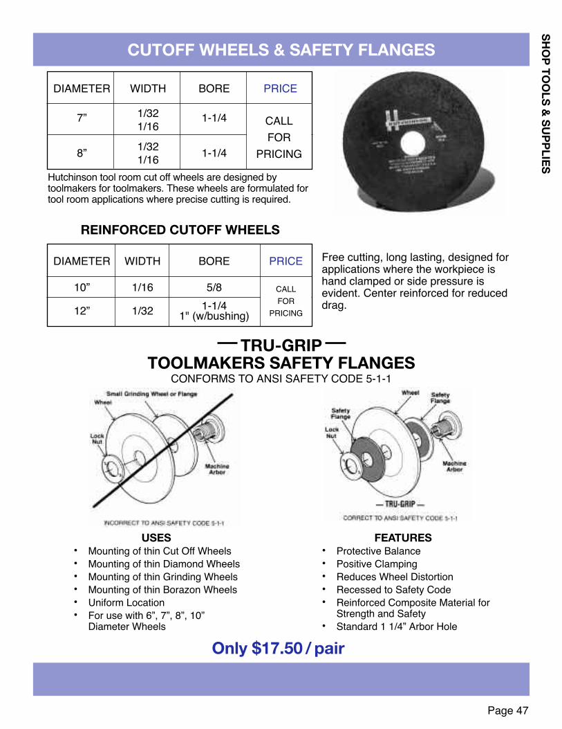
SHOP TOOLS & SUPPLIES
Page 47
CUTOFF WHEELS & SAFETY FLANGES
DIAMETER WIDTH BORE PRICE
7” 1/32 1-1/41/16
8” 1/32 1-1/41/16Hutchinson tool room cut off wheels are designed bytoolmakers for toolmakers. These wheels are formulated fortool room applications where precise cutting is required.
TRU-GRIP TOOLMAkERS SAFETY FLANGES
CONFORMS TO ANSI SAFETY CODE 5-1-1
USES• Mounting of thin Cut Off Wheels• Mounting of thin Diamond Wheels• Mounting of thin Grinding Wheels• Mounting of thin Borazon Wheels• Uniform Location• For use with 6”, 7”, 8”, 10”
Diameter Wheels
FEATURES• Protective Balance• Positive Clamping• Reduces Wheel Distortion• Recessed to Safety Code• Reinforced Composite Material for
Strength and Safety• Standard 1 1/4” Arbor Hole
Only $17.50 / pair
DIAMETER WIDTH BORE PRICE
10” 1/16 5/8 $9.901-1/412” 1/32 $11.801" (w/bushing)
REINFORCED CUTOFF WHEELS
Free cutting, long lasting, designed forapplications where the workpiece ishand clamped or side pressure isevident. Center reinforced for reduceddrag.
CALLFOR
PRICING
CALLFOR
PRICING

SHOP
TOO
LS &
SUP
PLIE
S
Page 48
DIAMOND WHEELS AND TOOLSTYPE 11V9 FLARING CUP DIAMOND WHEELS
TYPE 6A2C CUP STYLE DIAMOND WHEELS WITHCOUNTERSUNK BOLT HOLES
33⁄4 11⁄2 3/8
5 13⁄4 7/16
1/16 99.001/8 115.001/16 130.001/8 150.00
D T U X PRICEIN. IN. IN. IN. EACH AVAILABLE IN GRIT SIZES
320-(FINE)150-(MEDIUM)100-(COARSE)
Specify (H) hole size
AVAILABLE IN GRIT SIZES320-(FINE)
150-(MEDIUM)100-(COARSE)
100% CONCENTRATIONSpecify (H) hole size
100% CONCENTRATION
6 3/4 3/4 1/16 149.001/8 199.00
D T W X PRICEIN. IN. IN. IN. EACH
TYPE 1A1 STRAIGHT STYLE 6" DIAMOND WHEELS
1/8 1/8 114.001/4 1/16 128.001/4 1/8 138.003/8 1/8 169.001/2 1/8 190.00
T X PRICEIN. IN. EACH
75% CONCENTRATIONAVAILABLE IN GRIT SIZES
320-(FINE)150-(MEDIUM)100-(COARSE)
Specify (H) hole size
DIAMOND CLEANING STICK6” DIAMONDCUT-OFF WHEEL
.035 Thickness11⁄4” Hole1/4” Diamond Depth100% ConcentrationGRIT D10085.00 Each
Aluminum Oxide150 Grit1 x 1 x 6
6.79 Each
JIG GRINDING MANDRELS
(D)Diameter
.156
.187
.203
.218
.236
.250
.281
.312
.375
(H)Length
.250
.250
.250
.250
.250
.250
.250
.375
.375
(L)Neck.500.500.500.500.500.500———
PriceEach21.7522.4022.4023.1023.7524.4525.8028.5032.60
(D)Diameter
.390
.406
.437
.500
.562
.625
.750
.8751.000
(H)Length
.375
.375
.375
.375
.375
.375
.375
.375
.375
PriceEach36.0036.6539.3546.1548.2050.2061.7571.2588.90
1/4" Shank100 Grit3" Overall LengthAlso Available:1/8" or 3/8" ShankDiameters to .016
L
D
H
+ .0- .001

Page 49
SHOP TOOLS & SUPPLIES
DIAMOND TOOLS
Tool No. Style Cross Section Size (inches)NN-1 Oval .150 x .105NN-2 Half-round .218 x .072NN-3 Equaling .205 x .508NN-4 Square .096 x .096NN-5 Three Square .138 x .138NN-6 Round .118NN-7 Crossing .197 x .088NN-8 Barretts .205 x .067
Diamond PlatedNeedle Nose Files
3" Diamond length51⁄2" Overall length
1/8" shankAvailable in grit sizes:
200 FINE150 MEDIUM100 COARSE
$14.90 eachDiamond Plated Bore Laps
Diameter Length Priceof Diamond Each
3/16 1/2 34.397/32 1/2 35.701/4 1/2 39.11
9/32 1/2 41.215/16 1/2 44.8911/32 1/2 48.303/8 3/4 51.71
13/32 3/4 56.187/16 3/4 59.5915/32 3/4 69.83
1/2 1 77.969/16 1 84.795/8 1 96.34
11/16 1 105.533/4 1 114.457/8 1 123.641 1 132.83
STANDARD GRIT 220OTHER GRITS AVAILABLE
SCREW ADJUSTMENT EXPANDSDIAMETER
CBN PLATED ALSO AVAILABLESPECIFY BARREL OR BLIND HOLE
LAP WHEN ORDERINGNEEDLE EYE LAPS AVAILABLE TO
.030 DIA - CALL FOR PRICING
SINGLE END DIAMOND HAND HONE DOUBLE END DIAMOND HAND HONE
4 1/4 1/4 1!/46 3/8 3/8 1!/4
1/8 37.501/8 46.25
L W T L1 X PRICEIN. IN. IN. IN. IN. EACH
4 1/4 1/4 1!/46 3/8 3/8 1!/4
1/8 60.001/8 73.75
L W T L1 X PRICEIN. IN. IN. IN. IN. EACH
AVAILABLE INGRIT SIZES600-(FINE)
320-(MEDIUM)150-(COURSE)

Page 50
3/16 * * * — — —1/4 * * * * * —5/16 * * * * * —3/8 * * * * * *7/16 * * * * * —1/2 * * * * * *5/8 * * * * * *3/4 * * * * * *7/8 * * * * * *1 * * * * * *
1 1/8 — — * * * *1 1/4 * * * * * *1 3/8 — — * * * *1 1/2 — * * * * *1 5/8 — — * — * —1 3/4 — * * * * *
2 — — * * * *2 1/4 — — * * * *2 1/2 — — * * * *2 3/4 — — * * * *
3 — — * * * *3 1/4 — — — — * *3 1/2 — — — — * *3 3/4 — — — — — *
4 — — — — * *
1/2 * * * — — — — —5/8 * — * — — — — —3/4 * * * — * * — —7/8 * * * — — — — —1 * * * * * * * *
1 1/8 * — * — — — — *1 1/4 * * * * * * — *1 3/8 * — — — — * — *1 1/2 * * * * * * * *1 5/8 — * * — — * — —1 3/4 * * * * * * * *
2 * * * * * * * *2 1/4 * * * * * * * *2 1/2 * * * * * * * *2 3/4 * * * * * * * *
3 * * * * * * * *3 1/4 * * * — * * * *3 1/2 * * * * * * * *3 3/4 * — * — * — — —
4 * * * * * * * *4 1/2 — — * * * * * *
5 — — * * * * * *5 1/2 — — * — — — — —
6 — — * — * * * *
DOWEL PINS
• All pins are heat treated toRockwell 60-64C
• .001 oversized ± .0001Prices on application
• Made in USA
• Dowel pins can be customground to special diameters tomeet your requirements
NO MINIMUM ORDER
SHOP
TOO
LS &
SUP
PLIE
S
Length Diameter1/16 3/32 1/8 3/16 1/4 5/16
Length Diameter3/8 7/16 1/2 9/16 5/8 3/4 7/8 1”
D P RSTANDARD Point Crown height
Nom .0002 Oversized .001 Oversized Diameter or RadiusSize Max. Min. Max. Min. Max. Min. Max. Min.1/16 .0628 .0626 .0636 .0634 0.058 0.048 0.020 0.0083/32 .0941 .0939 .0949 .0947 0.089 0.079 0.031 0.0121/8 .1253 .1251 .1261 .1259 0.120 1.110 0.041 0.016
3/16 .1878 .1876 .1886 .1884 0.180 0.179 0.062 0.0231/4 .2503 .2501 .2511 .2509 0.240 0.230 0.083 0.031
5/16 .3128 .3126 .3136 .3134 0.302 0.290 0.104 0.0393/8 .3753 .3751 .3761 .3759 0.365 0.350 0.125 0.047
7/16 .4378 .4376 .4386 .4384 0.424 0.409 0.146 0.0551/2 .5003 .5001 .5011 .5009 0.486 0.471 0.167 0.0635/8 .6253 .6251 .6261 .6259 0.611 0.595 0.208 0.0783/4 .7503 .7501 .7511 .7509 0.735 0.715 0.250 0.0947/8 .8753 .8751 .8761 .8759 0.860 0.840 0.293 0.1091 1.0003 1.0001 1.0011 1.0009 0.980 0.960 0.333 0.125
*Call for current pricing

Page 51
SHOP TOOLS & SUPPLIES
NO MINIMUMORDER
*CALL FORCURRENTPRICING
303 STAINLESS DOWEL PINSLength1/25/83/47/811 1/41 1/21 3/422 1/233 1/24
3/16***********
——
1/8*************
1/4*************
5/16*************
3/8*************
1/2—**
—*********
5/8————*********
METRIC PULL DOWEL PINSLengthin MM202530354045505560707580100
8**********
—*
—
6**********
—*
—
10*************
12*************
16—************
20——***********
Lengthin MM202530354045505560707580100
METRIC DOWEL PINSLengthin MM1214161820253035404550556065708090100
5*********
—*****
———
4*********
—***
—*
———
6*
—*
—**********
—***
8*
—*
—*************
—
10——****************
12————**************
16————*******
—*
—*
—*
—
20—————**
—*
—*
—*
—**
—*
Lengthin MM1214161820253035404550556065708090100
DOWEL PINS

Page 52
SHOP
TOO
LS &
SUP
PLIE
S
SOCkET HEAD CAP & SET SCREWS
Length 4/40 5/40 6/32 8/32 10/24 10/32 1/4-20 5/16-18 3/8-16 1/2-13 5/8-11 3/4-101/4 * * * — — — — — — — — —3/8 * * * * * * * — — — — —1/2 * * * * * * * * — — — —5/8 * * * * * * * * — — — —3/4 * * * * * * * * * * — —1 — — — * * * * * * * — —
1 1/4 — — — — * * * * * * * —1 1/2 — — — — * * * * * * * *1 3/4 — — — — — — * * * * * *
2 — — — — — — * * * * * *2 1/4 — — — — — — — — — * * *2 1/2 — — — — — — — — — * * *
3 — — — — — — — — — * * *
FLAT HEAD SOCkET CAP SCREWS
SOCkET SET SCREWS – CUP POINT(OTHER POINTS AND DIAMETERS AVAILABLE
PRICES ON APPLICATION)
Length 4/40 6/32 8/32 10/24 10/32 1/4-20 5/16-18 3/8-161/4 * * * * * — — —3/8 * * * * * * — —1/2 * * * * * * * *5/8 — * * * * * * *3/4 — — * * * * * *1 — — — * * * * *
1 1/4 — — — — — — — *
BUTTON HEAD SOCkET CAP SCREWS
Length M8 M1016 * —20 * *25 * *30 * *35 * *40 * *45 * *50 * *55 * *60 * *65 * *70 * *75 * *
METRIC SOCkET HEAD CAPSCREWS
Length 0/80 1/72 2/56 3/48 4/40 5/40 6/32 8/32 10/24 10/321/16 — * * — — — — — — —3/32 * * * * — — — — — —1/8 * * * * * * * * — —3/16 * * * * * * * * * *1/4 * * * * * * * * * *5/16 — — — — * * * * * *3/8 — — — — * * * * * *1/2 — — — — * * * * * *5/8 — — — — — — — — * *3/4 — — — — — — — — * *1 — — — — — — — — — *
1 1/4 — — — — — — — — — *
Length 1/4-20 1/4-28 5/16-18 5/16-24 3/8-16 3/8-24 1/2-133/16 * * — — — — —1/4 * * * * * * —5/16 * * * * * * —3/8 * * * * * * —1/2 * * * * * * *5/8 * — * * * * *3/4 * — * * * * *1 * — * * * * *
1 1/4 * — * — * * *1 1/2 * — * — * * *
*Call for current pricing

Page 53
SOCkET HEAD CAP SCREWS
SHOP TOOLS & SUPPLIES
Also Available:COMPLETE LINE OFHOLO-kROME FASTENERSCALL 1-800-544-7934 TO REQUESTLATEST HOLO-kROME CATALOG
Length 0/80 1/72 2/56 3/48 4/40 5/40 6/32 6/40 8/32 8/36 10/24 10/32 1/4-20 1/4-281/8 * * — — — — — — — — — — — —
3/16 * * * * — — — — — — — — — —1/4 * * * * * * * — * — — — — —3/8 * * * * * * * * * * * * * *1/2 — — * * * * * * * * * * * *5/8 — — — — * * * * * — * * * *3/4 — — — — * * * * * * * * * *7/8 — — — — — — * — * — * * * —1 — — — — — — * — * — * * * *
1 1/4 — — — — — — — — * — * * * *1 1/2 — — — — — — — — * — * * * *1 3/4 — — — — — — — — — — * * * *
2 — — — — — — — — — — * * * *2 1/4 — — — — — — — — — — — — * —2 1/2 — — — — — — — — — — — — * —2 3/4 — — — — — — — — — — — — * —
3 — — — — — — — — — — — — * —
Length 5/16-18 5/16-24 3/8-16 3/8-24 7/16-14 1/2-13 1/2-20 5/8-11 3/4-10 1-8 1/2 * — * — — * — — — —5/8 * * * — — — — — — —3/4 * * * * * * — — — —7/8 * * * — * * — — — —1 * * * * * * * * — —
1 1/4 * * * * * * * * * —1 1/2 * * * * * * * * * —1 3/4 * * * * * * * * * —
2 * * * * * * * * * *2 1/4 * — * — * * * * * *2 1/2 * — * — * * * * * *2 3/4 * — * — * * — * * *
3 * — * — * * * * * *3 1/4 * — * — — * — * * *3 1/2 * — * — — * — * * *
4 — — * — — * — * * *4 1/2 — — * — — * — * * *
5 — — * — — * — * * *5 1/2 — — — — — * — * * *
6 — — — — — * — * * *6 1/2 — — — — — * — * * *
7 — — — — — * — * * *8 — — — — — * — * * *
*Call for current pricing

Page 54
SOFT FACE DEAD BLOWHammers, Mallets and Sledges with Replaceable Faces
All Lixie Dead Blow striking tool head castings feature an unobstructed cavity, partially filled with iron shot. Asthe hammer is struck on a surface, the urethane face absorbs a portion of the blow’s energy. The shot movesforward immediately behind the blow, dampening the rebound and insuring that the force of the blow istransmitted solidly to the struck surface. Lixie Dead Blow Hand Hammers and Mallets are available in 6 sizes,with a selection of two weights in each size. The rugged head casting is of either malleable iron (Heavy DeadBlow) or hi-tensile, non-sparking Aluminum (Light Dead Blow).
Lixie Dead Blow Sledges have the same features as the Hammers andMallets. They are used where a heavy blow is desired, yet still retain thehighly protective quality of Lixie urethane. They are available in 3 sizeswith 2 weights in each size furnished with smooth hickory grip handles.
HEAD HEAD OVERALL WEIGHT PRICEMODEL DIAM. LENGTH LENGTH (OUNCES) EACH
*100L-MH 1" 4-1/4" 11" 10 36.21
100H-MH 1" 4-1/4" 11" 14 36.66
*125L-MH 1-1/4" 4-7/8" 12" 14 40.07
125H-MH 1-1/4" 4-7/8" 12" 22 39.74
*150L-MH 1-1/2" 5-1/4" 13" 22 47.38
150H-MH 1-1/2" 5-1/4" 13" 30 47.40
*200L-MH 2" 6-1/4" 15" 38 66.02
200H-MH 2" 6-1/4" 15" 56 65.05
*250L-MH 2-1/2" 7" 17" 66 116.42
250H-MH 2-1/2" 7" 17" 100 100.63
*300L-MH 3" 8-1/2" 19" 116 157.24
300H-MH 3" 8-1/2" 19" 168 149.16
*250L-MH-32 2-1/2" 7-1/8" 32" 80 162.52
250H-MH-32 2-1/2" 7-1/8" 32" 114 159.44
*300L-MH-35 3" 8-1/2" 35" 120 206.61
300H-MH-35 3" 8-1/2" 35" 180 220.64
HAM
MER
S &
MAL
LETS
SLED
GES
HAMMERS FURNISHED COMPLETE WITH 2 FACESGrade of face may be interchanged without increase incost. Where not specified standard face makeup ofMedium and Hard (MH) will be furnished.*All L-Light Dead Blow models are sparkproof.
SEE PAGE 55 FOR AVAILABLE FACES
LIXIEDeadBlow
Sledge
LIXIEDeadBlowMallet
LIXIE HAMMERS AND MALLETS
SHOP
TOO
LS &
SUP
PLIE
S

Page 55
SHOP TOOLS & SUPPLIES
LIXIE HAMMERS AND MALLETS
MULTI HAMMERwith Replaceable Urethane Face
ONE HAMMER DOES THE JOB OF TWO! With a flip of the wristyou can switch from a sparkproof bronze to a soft, protectiveurethane face without fumbling for another hammer. Lixie’sexclusive all-purpose model has a machinist’s head cast in ourspecial bronze alloy, with the opposite face incorporatingreplaceable screw-in faces in your choice of 4 grades, soft to hard.The handle is Grade A hickory with an exclusive non-slip groovedhandle and special epoxy wedge construction. The All-Purposehammer comes in a choice of 3 sizes with face diameters of 1",1-1/4" or 1-1/2".
REPLACEABLE URETHANE SCREW-IN FACES
HEAD HEAD OVERALL WEIGHT PRICEMODEL DIAM. LENGTH LENGTH (OUNCES) EACH
AB 100-T 1" 3-7/8" 12-1/2" 16 43.10
AB 125-T 1-1/4" 4-3/8" 13" 26 53.88
AB 150-T 1-1/2" 5" 13" 36 73.80
HAMMERS FURNISHED COMPLETE WITH 1 URETHANE FACEGrade of face may be interchanged without increase in cost.Where not specified standard Tough grade (T) will be furnished. All are sparkproof.
NOTE: Order face diameter to coincide with hammer diameter.Faces packaged one each per container.
Lixie screw-type replaceable polyurethane faces are included on allLixie Dead Blow and Multi Hammers. They are available in six sizes,with a range of four hardnesses in each size. This permits customfitting a Lixie hammer to your individual requirements. Impervious tooils and most solvents, these solid polyurethane faces have highimpact absorption, yet will not mar, peen or deform the struck surface.
COLOR DENOTESHARDNESS
DIAMETER1" 1-1/4" 1-1/2" 2" 2-1/2" 3"
BROWN (Soft) 6.93 7.69 9.38 12.67 23.14 31.40
GREEN (Medium) 6.93 7.69 9.38 12.67 23.14 31.40
RED (Tough) 6.93 7.69 9.38 12.67 23.14 31.40
BLACk (Hard) 9.22 10.33 12.67 18.53 33.89 46.87
COLOR
To request full line brochure of Lixie Hammers –Call 1-800-544-7934

SHOP
TOO
LS &
SUP
PLIE
S
Page 56
STEEL SHIM STOCk
BRASS SHIM STOCk
Steel Shim Stock is low carbon mild steel cold rolled to a #1 hard temper. It is stiff and springy. The material can bepunched or sheared with minimum burring and distortion.
Use Brass Shim Stock where some stiffness is required and where corrosion problems exsist. 70% copper and 30% zincit has been cold rolled to a 1/2 hard temper, Rockwell hardness of 30T 56/68.
12 Pak – 1 Pc. each 6”x12”$ 39.33
.001 .0015 .002
.003 .004 .005
.006 .007 .008
.010 .012 .01515 Pak – 1 Pc. each 6”x12”
$ 45.82.001 .0015 .002.003 .004 .005.006 .007 .008.010 .012 .015.020 .025 .0314 Pak – 1 Pc. each 6”x50”
$ 41.61.001.002.003.005
THICKNESS PRICE EACH.001.0015.002.0025.003.004.005.006.007.008.009.010.012.015.018.020.025.031
$ 13.0815.548.958.73
11.3310.9410.009.569.969.89
10.3610.5410.3310.7312.1912.6013.4614.16
THICKNESS PRICE EACH.001.0015.002.0025.003.004.005.006.007.008.009.010.012.015.018.020.025.031
$ 27.0732.1918.5319.5023.6422.6420.6719.7920.6320.4821.4321.8321.3922.2025.2726.0927.8629.34
THICKNESS PRICE EACH.001.0015.002.003.004.005.006.007.008.009.010.012.015.020.025.031
$ 22.6422.7423.4624.2325.5326.4127.1828.5230.0832.3235.1738.0943.9951.5861.6172.89
THICKNESS PRICE EACH.001.0015.002.003.004.005.006.007.008.009.010.012.015.020.025.031
$ 41.6741.6741.6741.6743.7450.3454.7861.1361.1365.1065.1080.9889.53
107.99129.42142.92
12 Pak – 1 Pc. each 6”x12”$ 45.65
.001 .0015 .002
.003 .004 .005
.006 .007 .008
.010 .012 .01515 Pak – 1 Pc. each 6”x12”
$ 62.25.001 .0015 .002.003 .004 .005.006 .007 .008.010 .012 .015.020 .025 .0314 Pak – 1 Pc. each 6”x50”
$ 50.82.001.002.003.005
6” x 100” Rolls 6” x 180” Rolls Assortments
6” x 100” Rolls 6” x 180” Rolls Assortments
1008/1010 Full Hard, AISI1010, QQS 698
260 Half Hard
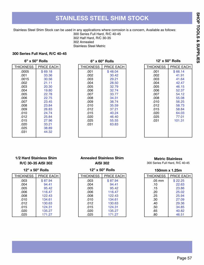
SHOP TOOLS & SUPPLIES
Page 57
STAINLESS STEEL SHIM STOCkStainless Steel Shim Stock can be used in any applications where corrosion is a concern, Available as follows:
300 Series Full Hard, R/C 40-45302 Half Hard, R/C 30-35302 AnnealedStainless Steel Metric
THICKNESS PRICE EACH.001.002.003.004.005.006.007.008.010.012.015.020.025.031
$ 66.1441.9141.6442.4746.1552.3754.1255.0856.2558.7358.8464.0377.01
101.31
THICKNESS PRICE EACH.001.002.003.004.005.006.007.008.009.010.012.015.020.025.031
$ 48.0430.4229.2128.5032.7932.7433.7734.3138.7435.5937.2140.2446.4055.5563.83
THICKNESS PRICE EACH.0005.001.0015.002.003.004.005.006.007.008.009.010.012.015.020.025.031
$ 69.1833.3630.5621.1120.3019.8022.7822.7523.4523.8426.8324.7425.8427.9633.2138.8944.32
THICKNESS PRICE EACH.003.004.005.006.008.010.012.015.020.025
$ 87.9494.4195.42
116.47122.43134.61130.63124.31135.27171.27
THICKNESS PRICE EACH.003.004.005.006.008.010.012.015.020.025
$ 87.9494.4195.42
116.47122.43134.61130.63124.31135.27171.27
THICKNESS PRICE EACH.05 mm.10.15.20.25.30.40.50.65.80
$ 22.2522.6323.8625.0225.9427.0929.3634.8540.8246.51
6” x 50” Rolls 6” x 60” Rolls 12’ x 50” Rolls
12” x 50” Rolls 12” x 50” Rolls 150mm x 1.25m
300 Series Full Hard, R/C 40-45
1/2 Hard Stainless ShimR/C 30-35 AISI 302
Annealed Stainless ShimAISI 302
Metric Stainless300 Series Full Hard, R/C 40-45

SHOP
TOO
LS &
SUP
PLIE
S
Page 58
AISI TYPE 0-1 OIL HARDENING GROUND FLAT STOCk
PriceThickness Width EachPriceThickness Width Each
PriceThickness Width EachPriceThickness Width Each
1/64
1/32
3/64
1/16
5/64
3/32
7/64
1/8
1/8
9/64
5/32
3/16
3/16
7/32
1/4
9/32
1/23/411-1/41-1/222-1/2341/23/411-1/41-1/222-1/23461/23/411-1/41-1/222-1/233-1/2461/43/81/25/83/411-1/41-1/21-3/422-1/233-1/2456810
93.0196.71
142.61106.46117.25145.66167.00200.08269.4016.8722.7926.5631.4836.3946.0155.7465.7285.11
150.3014.8119.0823.2627.3031.5039.9148.1456.5064.8688.54
106.3135.0217.5010.4411.9913.1915.9018.5621.3224.0126.7432.1337.5243.0648.3559.2370.07
105.05129.86
13.6416.8920.1923.4026.6933.2639.5346.1259.3785.9144.1124.2113.6416.8920.1923.4026.6929.9733.2639.8646.4659.5872.7385.86
128.41230.1716.2220.1523.9627.6931.6039.3749.2754.8570.33
110.9928.8110.3611.3011.9413.1714.6616.1919.1421.9424.8827.8730.8236.71
42.6648.5854.4966.3178.14
103.20116.96144.19171.56198.1416.3618.6422.0826.5628.6735.5049.0562.6026.7440.0023.2216.2119.8723.4926.9030.4434.0637.7244.8452.0959.3066.5080.9495.30
142.1125.7214.2015.3916.0717.6919.8721.2024.8528.2431.8735.4639.1246.3253.60
60.8768.0282.5397.00
144.24177.41210.8524.7121.1825.5129.8633.9138.2446.8955.9464.1681.39
115.9123.0435.2618.0319.6521.6023.4527.3330.8434.7438.2742.3950.0457.7065.3873.0680.7088.3596.06
107.88136.45154.37189.63225.07259.4423.9622.7027.0131.4135.3739.78
1/23/411-1/41-1/222-1/23461/43/81/23/411-1/41-1/21-3/422-1/234568101/23/411-1/41-1/222-1/23461/81/45/163/81/25/83/411-1/41-1/21-3/422-1/2
33-1/2456781012141/23/411-1/41-1/22345/321/43/81/23/411-1/41-1/21-3/422-1/233-1/245683/161/45/163/81/25/83/411-1/41-1/21-3/422-1/23
3-1/2456810127/321/23/411-1/41-1/222-1/23461/45/163/81/25/83/411-1/41-1/21-3/422-1/233-1/244-1/255-1/26781012149/321/23/411-1/41-1/2
Overall Length: 18"
Tolerance: Thickness ± .001Width + .005
– .0Also Available:36" Lengths • Oversize • Low Carbon • A-2, D-2, S-7

Page 59
AISI TYPE 0-1 OIL HARDENING GROUND FLAT STOCk
SHOP TOOLS & SUPPLIES
PriceThickness Width EachPriceThickness Width Each
PriceThickness Width EachPriceThickness Width Each
Overall Length: 18"
9/32
5/16
3/8
7/16
7/16
1/2
9/16
5/8
3/4
3/4
7/8
1
1-1/8
1-1/4
1-1/2
1-1/2
2
2-1/2
23465/163/81/25/83/411-1/41-1/21-3/422-1/233-1/24567810123/81/25/83/411-1/41-1/21-3/422-1/233-1/244-1/255-1/267810127/161/23/41
48.4665.8583.19
117.8424.9121.6923.5225.8128.0432.5936.6941.2545.7350.2759.3068.2977.3186.36
104.21126.94160.64181.49222.79264.3631.3428.6731.4434.1939.6044.6050.0657.1460.9971.8382.7593.67
104.54115.41126.26137.24148.09194.19219.42269.34319.5337.8134.1940.5146.83
52.6759.0171.6484.3196.96
119.21172.9135.2638.5541.8448.3954.7461.2768.0674.4587.60
100.76113.90127.08140.24154.29196.31239.16270.09325.11379.5842.3147.7255.0162.1669.4284.0646.1950.0057.5364.8472.3987.50
102.59117.71132.85147.95179.15209.3759.4468.2976.6285.4194.22
103.02120.59138.26155.83173.43191.04209.64244.83358.19432.00505.8674.4879.5188.9398.91
118.87158.94198.94279.9585.5095.31
105.84116.31126.81147.83168.76189.76210.74253.69295.71431.21520.46609.64109.02126.96150.99199.00247.07344.21120.38133.34159.38185.31211.19263.08316.01367.91155.59
185.34215.11257.20310.28429.72594.79237.44312.29387.22515.50408.19
1-1/41-1/222-1/23461/25/83/411-1/41-1/21-3/422-1/233-1/244-1/2567810129/163/411-1/41-1/225/83/411-1/41-1/222-1/233-1/24563/411-1/41-1/21-3/4
22-1/233-1/244-1/256810127/811-1/41-1/2234611-1/41-1/21-3/422-1/233-1/2456810121-1/81-1/223461-1/41-1/222-1/234561-1/2
23456823462-1/2
Tolerance:
Thickness ± .001Width + .005
– .0
Also Available:36" Lengths
OversizeLow CarbonA-2, D-2, S-7

Page 60
SOLID CARBIDE PLAIN PRESS FIT BUSHINGS
.0135to
.0625
.0625to
.0995
.0980to
.1406
.1250to
.1935
.1875to
.2570
.1875to
.3160
.3125to
.4375
.3750to
.5312
.5000to
.6250
.6250to
.7500
.7500to
1.0000
.1578
.1575
.2046
.2043
.2516
.2513
.3141
.3138
.4078
.4075
.5017
.5014
.6267
.6264
.7518
.7515
.8768
.8765
1.00181.0015
1.37721.3768
1/45/163/81/21/45/163/81/21/45/163/81/23/41/45/163/81/23/411/45/163/81/23/41
1-3/83/81/23/41
1-3/81-3/43/81/23/41
1-3/81-3/42-1/81/23/41
1-3/81-3/42-1/81/23/41
1-3/81-3/42-1/81/23/41
1-3/81-3/42-1/82-1/23/41
1-3/81-3/42-1/82-1/2
PC-10-4PC-10-5PC-10-6PC-10-8PC-13-4PC-13-5PC-13-6PC-13-8PC-16-4PC-16-5PC-16-6PC-16-8PC-16-12PC-20-4PC-20-5PC-20-6PC-20-8PC-20-12PC-20-16PC-26-4PC-26-5PC-26-6PC-26-8PC-26-12PC-26-16PC-26-22PC-32-6PC-32-8PC-32-12PC-32-16PC-32-22PC-32-28PC-40-6PC-40-8PC-40-12PC-40-16PC-40-22PC-40-28PC-40-34PC-48-8PC-48-12PC-48-16PC-48-22PC-48-28PC-48-34PC-56-8PC-56-12PC-56-16PC-56-22PC-56-28PC-56-34PC-64-8PC-64-12PC-64-16PC-64-22PC-64-28PC-64-34PC-64-40PC-88-12PC-88-16PC-88-22PC-88-28PC-88-34PC-88-40
Std.DrillSizeA
ActualO.D.B
Length
C
Symbolfor O.D.FinishGround
SOLID CARBIDE SLIP& FIXED RENEWABLE BUSHINGS
ALSO AVAILABLEPRICES UPON REQUEST
AVAILABLE IN DRILL SIZESUP TO 1.750
PRICES ON REQUEST
STANDARD I.D. TOLERANCESUp to 1/4 Nominal +.0001/+.0004Over 1/4 to 3/4 Nominal +.0001/+.0005Over 3/4 to 1-1/2 Nominal +.0002/+.0006Over 1-1/2 to 1-3/4 Nominal +.0003/+.0007
CounterboreUnless otherwise specified, all Carbide Bushings aresupplied without counterbore. (Carbide Bushings withcounterbore are priced as specials.)
SHOP
TOO
LS &
SUP
PLIE
S

Page 61
SHOP TOOLS & SUPPLIES
CARBIDE HEAD PRESS FIT BUSHINGS
.0135to
.0625
.0625to
.0995
.0980to
.1406
.1250to
.1935
.1875to
.2570
.1875to
.3160
.3125to
.4375
.3750to
.5312
.5000to
.6250
.6250to
.7500
.7500to
1.0000
.1578
.1575
.2046
.2043
.2516
.2513
.3141
.3138
.4078
.4075
.5017
.5014
.6267
.6264
.7518
.7515
.8768
.8765
1.00181.0015
1.37721.3768
1/45/163/81/21/45/163/81/21/45/163/81/23/41/45/163/81/23/411/45/163/81/23/41
1-3/83/81/23/41
1-3/81-3/43/81/23/41
1-3/81-3/42-1/81/23/41
1-3/81-3/42-1/81/23/41
1-3/81-3/42-1/81/23/41
1-3/81-3/42-1/82-1/23/41
1-3/81-3/42-1/82-1/2
HC-10-4HC-10-5HC-10-6HC-10-8HC-13-4HC-13-5HC-13-6HC-13-8HC-16-4HC-16-5HC-16-6HC-16-8HC-16-12HC-20-4HC-20-5HC-20-6HC-20-8HC-20-12HC-20-16HC-26-4HC-26-5HC-26-6HC-26-8HC-26-12HC-26-16HC-26-22HC-32-6HC-32-8HC-32-12HC-32-16HC-32-22HC-32-28HC-40-6HC-40-8HC-40-12HC-40-16HC-40-22HC-40-28HC-40-34HC-48-8HC-48-12HC-48-16HC-48-22HC-48-28HC-48-34HC-56-8HC-56-12HC-56-16HC-56-22HC-56-28HC-56-34HC-64-8HC-64-12HC-64-16HC-64-22HC-64-28HC-64-34HC-64-40HC-88-12HC-88-16HC-88-22HC-88-28HC-88-34HC-88-40
1/4
19/64
23/64
27/64
1/2
39/64
51/64
59/64
1-7/64
1-15/64
1-39/64
3/32
3/32
3/32
1/8
5/32
7/32
7/32
7/32
1/4
5/16
3/8
Std.DrillSizeA
ActualO.D.B
Length
C
Symbolfor O.D.FinishGround F G
SOLID CARBIDE SLIP& FIXED RENEWABLE BUSHINGS
ALSO AVAILABLEPRICES UPON REQUEST
AVAILABLE IN DRILL SIZESUP TO 1.750
PRICES ON REQUEST
STANDARD I.D. TOLERANCESUp to 1/4 Nominal +.0001/+.0004Over 1/4 to 3/4 Nominal +.0001/+.0005Over 3/4 to 1-1/2 Nominal +.0002/+.0006Over 1-1/2 to 1-3/4 Nominal +.0003/+.0007
HEADDIMENSIONS

Page 62
STEEL FEELER GAGE STOCk
Steel gage stock is madefrom fine quality 1095tempered spring steel andetched every six inches forpositive identification.
TOLERANCE FOR.020 & LARGER = +- .0005
FOR .019 & SMALLERSEE PAGE 63
Additional sizes and materials available.
Call for pricing anddelivery.
Thickness
.001
.0015
.002
.0025
.003
.004
.005
.006
.007
.008
.009
.010
.011
.012
.013
.014
.015
.016
.017
.018
.019
.020
.021
.022
.023
.024
.025
.026
.027
.028
.029
.030
.031
.032
.033
.034
.035
.036
.037
.038
Strips1/2 x 12”
$4.672.502.502.562.502.032.032.031.791.791.791.791.791.791.791.791.791.791.791.791.791.791.791.791.791.791.791.791.791.791.791.791.921.921.921.921.922.162.162.16
Coils1/2 x 25’$93.4349.9249.9251.2149.9240.6436.5736.5732.2632.2632.2632.2632.2632.2632.2632.2632.2632.2632.2632.2632.2632.2632.2632.2632.2632.2632.2635.8435.8435.8435.8435.8438.4038.4038.4038.4038.4043.2043.2043.20
Thickness
.039
.040.041-.045.046-.055.056-.065.066-.075.076-.090.091-.125
Strips1/2 x 12”
2.162.168.579.29
10.0010.3610.7211.43
Available in 1/2”wide (12.7 MM)twelve inch (300 MM)lengths or25’ (7.62 M) rolls
Coils1/2 x 25’
43.2043.20
AVAILABLEIN .001
INCREMENTS—NOT
AVAILABLEIN COIL
Metric - SteelThickness Strips Coils
12.7mm x 300 mm 12.7mm x 7.62m
.04mm $ 4.64 $ 99.99
.05 4.29 92.86
.06 3.93 85.71
.07 3.57 78.57
.08 3.57 78.57
.09 3.35 71.43
.10 3.35 71.43
.15 3.22 67.86
.20 3.22 67.86
.25 3.22 67.86
.30 3.22 67.86
.35 3.22 67.86
.40 3.22 67.86
.45 3.22 67.86
.50 3.22 67.86
.55 3.29 69.29
.60 3.29 69.29
.65 3.29 69.29
.70 3.28 69.29
.75 3.29 69.29
.80 3.36 71.43
.85 3.36 71.43
.90 3.36 71.43
.95 3.36 71.431.00 3.36 71.431.50 10.72 —2.00 11.43 —2.50 12.14 —3.00 12.14 —
SHOP
TOO
LS &
SUP
PLIE
S

SHOP TOOLS & SUPPLIES
Page 63
STAINLESS STEEL FEELER GAGE STOCk
STAINLESS STEELGAGE STOCK ISTYPE 301 EXTRAFULL HARD OR HIGHYIELD, WITH A #1ROUND EDGE. LIKETHE STEEL STOCKIT IS ETCHED EVERYSIX INCHES FORPOSITIVE IDENTIFICATION.
AVAILABLE IN 1/2” AND1” WIDTHS, TWELVEINCH LENGTHS OR 25’ ROLLS.
SPECIAL LENGTHS,WIDTHS AND THICKNESS ON REQUEST.
STRIPS COILS STRIPS COILS TOLERANCE
Thickness 1/2 x 12” 1/2 x 25’ 1 x 12” 1 x 25’ +/-.0005 $7.73 $154.63 $15.46 $321.43.001 6.08 121.32 12.13 242.63.0015 4.21 110.75 8.43 168.57.002 3.64 72.86 7.28 145.72.0025 4.64 92.71 9.27 185.43.003 3.64 72.86 7.28 145.72.004 2.78 55.32 5.53 110.63.005 2.78 49.79 5.53 99.57.006 2.78 49.79 5.53 99.57.007 2.78 49.79 5.53 99.57.008 2.78 49.79 5.53 99.57.009 2.78 49.79 5.53 99.57.010 2.78 49.79 5.53 99.57.011 3.01 54.26 6.03 108.52.012 3.01 54.26 6.03 108.52.013 3.01 54.26 6.03 108.52.014 3.01 54.26 6.03 108.52.015 3.01 54.26 6.03 108.52.016 3.31 61.72.017 3.31 61.72.018 3.31 61.72.019 3.31 61.72.020 3.31 61.72.021 3.87 69.59.022 3.87 69.59.023 3.87 69.59.024 3.87 69.59.025 3.87 69.59.031 3.87 69.59
.00005
.00012
.00012
.00016
.00016
.00020
.00020
.00024
.00028
.00028
.00031
.00031
.00035
.00035
.00035
.00043
.00043
.00043
.00047
.00047
.00047
.00047
.00050
.00050
.00050
.00050
.00050
.00050
.00050
Not Available
inCoils

GRADE 25 CHROME STEEL (R/C 60 MIN.)
Page 64
INSPECTION BALL kITS
INSP
ECTI
ON &
GAG
ING
Inspection ball kits are available fromstock in the 14 most popular English
sizes from 3/32” to 1.00”, individually orall in a kit. The kit for each individual
size contains 7 balls. A nominalfractional ball as well as one each of a
+.002”, +001”, +0005”, +0002”, and -.001”, -002”. Kit BK-14 consists of all14 individual size kits. The inspection
ball kits are also excellent for ball sizingparts. Ball sizing is basically pushing a
ball through a hole or tube whichproduces a certain finish or size.
Grade 25BASIC DIAMETER
TOLERANCE = +- .0001
DEVIATION FROMSPHERICAL FORM
.000025
DECIMAL DIAMETER BALLS, OTHER MATERIALS AND TOLERANCES AVAILABLE
CALL FOR PRICING & DELIVERY
Part # Nominal Size Price
BK-14 —— $493.07
093-BK 3/32” 2.381 mm 42.81125-BK 1/8” 3.175 mm 42.81156-BK 5/32” 3.969 mm 42.81187-BK 3/16” 4.763 mm 42.81218-BK 7/32” 5.556 mm 42.81250-BK 1/4” 6.35 mm 42.81312-BK 5/16” 7.938 mm 44.50375-BK 3/8” 9.525 mm 44.50437-BK 7/16” 11.113 mm 44.50500-BK 1/2” 12.7 mm 41.21625-BK 5/8” 15.875 mm 41.21750-BK 3/4” 19.05 mm 51.04875-BK 7/8” 22.225 mm 61.10100-BK 1” 25.4 mm 61.10
14 Sizes From3/32” - 1” Kit

Page 65
INSPECTION & GAGING
CLASS X MEYER GAGE MG-25 SERIES
MG-25 PIN GAGE SETSIN .0001” INCREMENTS OR .01mm INCREMENTS
Used as masters to calibrate measuring equipmentand check linearity of comparators, micrometers,and calipers. These “Tenth Step” gage sets haveunlimited applications, such as quality controlinspection, prototype work and production layout.Inspectors select from the range of pins to find thesize of a hole or slot. These round masters simulatea cylindrical part which unlike flat blocks can detectuneven wear on the tips of micrometers andcalipers. The thin “line” of contact detects unevenface wear better than flat gage blocks with largecontact area.
SEE PAGE 67 FORMORE CLASS X GAGE SETS
FEATURES:• Each set contains 25 pieces of Class X tolerance
(.00004”) gage pins. Traceable to NIST.• Choice of two tolerances Plus (+.00004”) or
Minus (-.00004”).• Sets consist of a center nominal size, and 12
gages larger in .0001” steps and 12 gagessmaller in .0001” steps.
• Each gage is inspected and has a 2 micro-finishor better.
• Heat treated and through hardened to 60-62Rockwell C.
• All pin gages over .060” or 1.51mm are lasermarked with size direction of tolerance and serialnumber for traceability.
GAGE SET NO. NOMINAL SIZE RANGE SET PRICE
English or MetricMG1-25 .0110 to .0609 .28mm to 1.54mm $340.09MG2-25 .0610 to .2509 1.55mm to 6.37mm $169.19MG3-25 .2510 to .5009 6.38mm to 12.72mm $195.05MG4-25 .5010 to .7499 12.73mm to 19.04mm $269.17MG5-25 .7500 to .8129 19.05mm to 20.64mm $376.86
To order simply select your nominal size from any .0001” Englishor .01mm Metric increment and direction of tolerance. Then referto the above chart to find the set price.

WTH-0 mm .22mm - 1.50mm 65 106.37 4.61WTH-01 mm .23mm - 1.51mm 65 106.37 4.61WTH-1 mm 1.52mm - 7.70mm 310 374.99 4.19WTH-11 mm 1.53mm - 7.71mm 310 374.99 4.19WTH-2 mm 7.72mm - 12.70mm 250 403.63 4.19WTH-21 mm 7.73mm - 12.71mm 250 403.63 4.19WTH-3 mm 12.72mm - 15.30mm 130 447.27 5.28WTH-31 mm 12.73mm - 15.31mm 130 447.27 5.28WTH-4 mm 15.32mm - 17.80mm 125 474.54 8.28WTH-41 mm 15.33mm - 17.81mm 125 474.54 8.28WTH-5 mm 17.82mm - 20.36mm 128 563.35 9.95WTH-51 mm 17.83mm - 20.37mm 128 563.35 9.95WTH-6 mm 20.38mm - 22.04mm 84 674.41 11.65WTH-61 mm 20.39mm - 22.05mm 84 674.41 11.65WTH-7 mm 22.06mm - 23.72mm 84 778.79 13.05WTH-71 mm 22.07mm - 22.73mm 84 778.79 13.05WTH-8 mm 23.74mm - 25.40mm 84 800.19 14.68WTH-81 mm 23.75mm - 25.41mm 84 800.19 14.68
Page 66
WTH-0 .011 - .060 50 81.82 3.76WTH-0-5 .0115 - .0605 50 81.82 3.76WTH-1 .061 - .250 190 184.09 3.36WTH-1-5 .0615 - .2505 190 184.09 3.36WTH-10 .011 - .250 240 252.27 —WTH-105 .0115 - .2505 240 252.27 —WTH-2 .251 - .500 250 272.72 3.36WTH-2-5 .2515 - .5005 250 272.72 3.36WTH-3 .501 - .625 125 320.46 4.61WTH-3-5 .5015 - .6255 125 320.26 4.61WTH-4 .626 - .750 125 354.54 6.70WTH-4-5 .6265 - .7505 125 354.54 6.70WTH-5 .751 - .832 82 602.16 10.05WTH-5-5 .7515 - .8325 82 602.16 10.05WTH-6 .833 - .916 84 702.50 11.49WTH-6-5 .8335 - .9165 84 702.50 11.49WTH-7 .917 - 1.000 84 735.96 11.88WTH-7-5 .9175 - 1.0005 84 735.96 11.88
SeparateGage No. of Member
Set Number Gage Size Members Price Price
METRIC GAGE SETS
FEATURES• All Gages 2" long• No sharp edges• Boxes and Gages both marked
(WTH-0 pins not etched)• 8 Micro finish or better• All english gages are inspected
within .0001 tolerance limits• All metric gages are inspected within
.0025mm tolerance limits• Heat treated to a hardness of
Rockwell C 60-62• Each set packaged in its own
plastic case
USES• Checking locations.• Measuring hole sizes and depths• Go and No-Go gaging.• Setting micrometers.• Checking distances between holes.
IMPORTANT: SPECIFY PLUS OR MINUS TOLERANCEWHEN ORDERING GAGES
INSP
ECTI
ON &
GAG
ING
IN .001 INCREMENTSIN .02mm INCREMENTS
PRECISION PLUG GAGE SETS
PLASTIC CASESEACH HOLE SIZE MARKED ON INSERT.Plastic insert for WTH-0 set .............................................. $16.53 eachPlastic insert for WTH-1 thru WTH-8 sets ......................... 33.06 eachPlastic case for WTH-0 set ................................................ 16.53 eachPlastic case for WTH-1 thru WTH-7 sets .......................... 33.06 eachPlastic case with insert for WTH-0 set .............................. 33.06 eachPlastic case with insert for WTH-1 thru WTH-7 sets ........ 66.13 each
SeparateGage No. of Member
Set Number Gage Size Members Price Price

Page 67
CLASS X GAGE SETS .001 INCREMENTSSeparate
GageRange
Number of MemberSet Members Price Price
WTH-OX .011” -.060” 50 445.40 16.64WTH-O5X .0115 -.0605 50 445.40 16.64WTH-1X .061 - .250 190 1170.43 16.64WTH-15X .0615 - .2505 190 1170.43 16.64WTH-2X .251 - .500 250 1548.18 13.45WTH-25X .2515 - .5005 250 1548.18 13.45WTH-3X .501 - .625 125 1314.76 19.31WTH-35 .5015 - .6255 125 1314.76 19.31WTH-4X .626 - .750 125 1393.36 19.31WTH-45 .6265 - .7505 125 1393.36 19.31WTH-5X\ .751 - .832 82 1170.66 23.70WTH-55X .7515 -. 8325 82 1170.66 23.70WTH-6X .833 - .916 84 1232.59 23.70WTH-65X .8335 - .9165 84 1232.59 23.70WTH-7X .917 - 1.000 84 1413.61 23.70WTH-75X .9175 - 1.0005 84 1413.61 23.70
PRECISION PLUG GAGE SETS
GAGE SET LIBRARIES: Conveniently store all your gages in one locationIMPORTANT! Specify plus or minus tolerance when ordering gages
INSPECTION & GAGING
.000040 tolerance • Each set packaged inPlastic Case and Insert.
.0001 (CLASS Z) LIBRARY SERIESModel Number Wt./lbs. Range Number of members PriceL-S 87 .011” - .625” (615 gages) 1,021.78L-C 120 .011” - .750” (740 gages) 1,479.96L-1 120 .061” - .750” (690 gages) 1,413.05L-2 95 .061” - .5005” (880 gages in .0005” increments) 1,198.95L-2C 96 .011” - .5005” (980 gages in .0005” increments) 1,332.76L-3* 240 .061” - 1.000” (940 gages) 3,602.19L-4* 240 .011” - 1.000” (990 gages) 3,669.10L-5 140 .751” - 1.000” (250 gages) 2,356.41
.00004 (CLASS X) LIBRARY SERIESModel Number Wt./lbs. Range Number of members PriceL-CX 120 .011” - .750” (740 gages) 5,804.50L-1X 122 .061” - .750” (690 gages) 5,382.91L-2X 98 .061” - .5005” (880 gages in .0005 increments) 6,049.82L-2CX 100 .011” - .5005” (980 gages in .0005” increments) 5,291.21L-3X* 260 .061” - 1.000” (940 gages) 9,093.79L-4X* 250 .011” - 1.000” (990 gages) 9,453.44
* Consists of one seven drawer cabinet.
METRIC LIBRARY SERIES (.0025mm)Model Number Wt./lbs. Range Number of members PriceL-10 mm 124 1.52mm - 17.80mm (815 gages) 1,877.18L-11 mm 124 1.53mm - 17.81mm (815 gages) 1,877.18L-20 mm 183 17.82mm - 25.40mm (380 gages) 2,970.61L-21 mm 183 17.83mm - 25.41mm (380 gages) 2,970.61L-30 mm** 305 1.52mm - 25.40mm (1195 gages) 4,847.77L-31 mm** 305 1.53mm - 25.41mm (1195 gages) 4,847.77**Consists of 2 four drawer cabinets
Upgrade Existing SetsL-E 4 38 four drawer cabinet empty 354.60L-IN 4 46 four drawer cabinet with four inserts of your choice 434.88

.0030-.0049 ........... 14.50
.076 MM - .126 MM
.0050-.0069 ........... 13.50
.127 MM - .176 MM
.0070-.0099 ........... 11.50
.177 MM - .253 MM
.0100-.0200 ............. 4.06
.254 MM - .508 MM
.0201-.0312 ............. 3.86
.511 MM - .793 MM
.0313-.0938 ............. 3.35
.795 MM - 2.383 MM
.0939 - .1250 ........... 3.542.385MM - 3.175 MM.1251 - .1875............ 4.573.178 MM - 4.763 MM.1876 - .2500 ........... 4.984.765 MM - 6.350 MM
Page 68
Single or Double End Handlesfor above gages
Handle Size PriceNumber Range Each
1W .000 - .075 7.852W .075 - .180 8.103W .180 - .281 9.304W .281 - .406 11.505W .406 - .510 13.806W .510 - .635 17.207W .635 - .760 19.858W .760 -1.010 29.60
All handles supplied complete withbushings.
Hutchinson HSS gages are an ideal lowcost solution to a variety of dimensioningproblems.
All gage members are made of M2 highspeed steel hardness “C” 62-64.
YOUR CHOICEOF THREETOLERANCES
+ .0002 •
+.0000 •
+.0001- .0000 - .0002 - .0001
Standard Plug Gage Classes For Product TolerancesNormal practice for product gage tolerance is to allow 10% of the productto be equally divided between “go” and “no-go”. In the case of plug gages,“go” is normally a plus tolerance and “no-go” is normally a minustolerance.
Standard Gagemakers’ Tolerance ChartSize Range
To andAbove including.0009 - .010 .000005 .00001 .00002 .00004 .00007 .00010.010 - .029 .000005 .00001 .00002 .00004 .00007 .00010.029 - .825 .000005 .00001 .00002 .00004 .00007 .00010.825 - 1.510 .000008 .000015 .00003 .00006 .00009 .00012
1.510 - 2.510 .00001 .00002 .00004 .00008 .00012 .000162.510 - 4.510 .000013 .000025 .00005 .00010 .00015 .000204.510 - 6.510 .000017 .000033 .000065 .00013 .00019 .000256.510 - 9.010 .00002 .00004 .00008 .00016 .00024 .000329.010 - 12.260 .000025 .00005 .00010 .00020 .00030 .00040
CLASS CLASS CLASS CLASS CLASS CLASSXXXX XXX XX X Y Z
PLEASE USE THIS CHART FOR GAGESON THE FOLLOWING PAGES
INSP
ECTI
ON &
GAG
ING REVERSIBLE PLUG GAGES
.8751 - .9375 ............ 14.4922.228 MM - 23.813 MM.9376-1.0000 ............ 15.8223.815 MM - 25.400 MM1.0001-1.0625 .......... 19.5425.403 MM - 26.988 MM1.0626-1.1250. ......... 21.7726.990 MM - 30.163 MM1.1251 - 1.2500......... 25.8930.165 MM - 31.750 MM1.2501 - 1.3125......... 27.6131.753 MM - 33.338 MM1.3126 - 1.3750 ........ 30.2033.340 MM - 34.925 MM1.3751 - 1.4375......... 33.7134.928 MM - 36.513 MM 1.4376 - 1.5000......... 37.0836.515 MM - 38.100 MM
.2501-.3125 ................. 5.436.353 MM - 7.938 MM.3126 - .3750 .................5.737.940 MM - 9.525 MM.3751-.5000 ................. 6.459.528. MM - 12.700 MM.5001 - .5625 ............... 7.6912.703 - 14.288 MM.5626 - .6250 ................ 8.3114.290 MM - 15.875 MM.6251 - .6875 ............... 9.3215.878 MM - 17.463 MM.6876 - .7500 .............. 10.1117.465 MM - 19.050 MM.7501 - .8125 .............. 11.3319.053 MM - 20.638 MM.8126 - .8750 .............. 12.3420.640 MM - 22.225 MM
2” LONG HSS GAGE MEMBER PRICES

Page 69
SIZE RANGE STD GO MEMBER ONLY STD NO GO MEMBER ONLY HANDLEAbove - Through CLASS Length Steel Chrome Length Steel Chrome No. Price
TRILOCkS - STEEL AND CHROME
Additional sizes available through 8.010 in.
See page 74 for Progressive Trilocks
Trilocks are also available in Carbide.Call for pricing and delivery
INSPECTION & GAGING
XX 83.51 167.02 3/4 in. 75.57 151.14.760 IN - .947 IN X 11/4 IN 70.71 141.42 19.1MM 65.02 130.04 2 1 ⁄ 2 10.0719.30 MM - 24.05 MM Y 31.8 MM 60.67 121.34 55.82 111.64Z 50.46 100.92 47.45 94.90
XX 84.77 169.54 3/4in. 76.40 152.80.947 IN - 1.135 IN X 13/8 IN 72.63 145.26 19.1 MM 66.44 132.88 3 1 ⁄ 2 11.2824.05 MM - 28.83 MM Y 34.9 MM 62.35 124.70 57.07 114.14Z 53.81 107.62 50.46 100.92
XX 91.04 182.08 3/4 IN. 81.67 163.341.135 IN - .1.510 IN X 11/2 IN. 79.42 158.84 19.1 MM 72.46 144.92 4 1 ⁄ 2 13.2828.83 MM - 38.35 MM Y 38.1 MM 65.86 131.72 60.08 120.16Z 55.82 111.64 51.80 103.60
XX 134.64 269.28 122.00 244.001.510 IN - 2.010 IN X 17/8 IN 113.80 227.60 7/8 IN 99.24 198.48 5 1 ⁄ 2 15.71
38.35 MM - 51.05 MM Y 47.8 MM 102.25 204.50 22.2 MM 89.17 178.34Z 83.34 166.68 77.99 155.98
XX 161.66 323.32 147.10 194.202.010 IN - 2.510 IN X 2 IN 134.64 269.28 7/8 IN 122.00 244.00 6 16.43
51.05 MM - 63.75 MM Y 50.8 MM 119.15 238.30 22.2 MM 104.18 208.36Z 100.17 200.34 88.70 177.40
XX 183.45 366.90 161.25 322.502.510 IN - 3.010 IN X 2 IN 156.40 312.80 1 IN 130.79 261.58 7 22.07
63.75 MM - 76.45 MM Y 50.8 MM 134.64 269.28 25.4MM 117.24 234.48Z 111.55 223.10 101.00 202.00
XX 224.01 448.02 193.12 386.243.010 IN - 3.510 IN X 2 IN 171.29 342.58 1 IN 159.41 318.82 7 22.07
76.45 MM - 89.15 MM Y 50.8 MM 159.91 319.82 25.4 MM 139.57 279.14Z 137.06 274.12 120.16 240.32
XX3.510 IN - 4.010 IN X 2 1/8 IN 1 IN 7 22.07
89.15 MM - 101.85 MM Y 54.0 MM 25.4 MMZ
XX4.010 IN - 4.510 IN X 2 1/8IN 1 IN 7 22.07
101.85 MM - 114.55 MM Y 50.8 MM 25.4 MMZ
XX4.510 IN - 5.010 IN X 2 1/8 IN 1 IN 7 22.07
114.55MM - 127.25 MM Y 54.0 MM 25.4 MMZ
XX5.010 IN - 5.510 IN X 2 1/8 IN 1 IN 7 22.07
127.25 MM - 139.95 MM Y 54.0 MM 25.4 MMZ
XX5.510 IN - 6.010 IN X 2 1/8 IN 1 IN 7 22.07
139.95 MM - 152.65 MM Y 54.0 MM 25.4 MMZ
XX6.010 IN - 6.510 IN X 2 1/8 IN 1 IN 7 22.07
152.65 MM - 165.35 MM Y 54.0 MM 25.4 MMZ
XX6.510 IN - 7.010 IN X 2 1/8 IN 1 IN 7 22.07
165.35MM - 178.05MM Y 54.0 MM 25.4 MMZ
Priceson
Application
Priceson
Application

Page 70
Size / Range Tolerance Reversible Go or No Go AGD HandleTo and
Class in Member single or double endAbove Including inches Length Steel Carbide No. Price
XX .00002 47.00 —.011 IN - .020 IN X .00004 2 IN 39.00 — 1 W 7.85
.279 MM - .508 MM Y .00007 50.8 MM 33.00 —Z .00010 32.00 —
XX .00002 44.00 —.020 IN - .030 IN X .00004 2 IN 36.00 — 1 W 7.85
.508 MM - .762 MM Y .00007 50.8 MM 33.00 —Z .00010 29.00 —
XX .00002 34.00 —.030 IN - .040 IN X .00004 2 IN 19.00 — 1 W 7.85
.762 MM - 1.02 MM Y .00007 50.8 MM 17.00 —Z .00010 14.00 —
XX .00002 34.00 85.00.040 IN - .075 IN X .00004 2 IN 19.00 80.15 1 W 7.85
1.02 MM - 1.91 MM Y .00007 50.8 MM 17.00 75.30Z .00010 14.00 70.40
XX .00002 27.00 85.00.075 IN - .116 IN X .00004 2 IN 22.00 80.15 2 W 8.10
1.91 MM - 2.92 MM Y .00007 50.8 MM 21.00 75.30Z .00010 17.00 70.40
XX .00002 27.00 54.65.116 IN - .130 IN X .00004 2 IN 22.00 51.00 2 W 8.10
2.92 MM - 3.30 MM Y .00007 50.8 MM 21.00 47.35Z .00010 17.00 44.95
XX .00002 27.00 57.05.130 IN - .180 IN X .00004 2 IN 22.00 53.40 2 W 8.10
3.30 MM - 4.57 MM Y .00007 50.8 MM 21.00 49.80Z .00010 17.00 47.35
XX .00002 28.00 60.70.180 IN - .230 IN X .00004 2 IN 22.00 57.05 3 W 9.30
4.57 MM - 5.84 MM Y .00007 50.8 MM 21.00 53.40Z .00010 18.00 49.80
XX .00002 28.00 69.20.230 IN - .281 IN X .00004 2 IN 22.00 65.55 3 W 9.30
5.84 MM - 7.14 MM Y .00007 50.8 MM 21.00 61.90Z .00010 18.00 58.25
XX .00002 32.00 71.65.281 IN - .344 IN X .00004 2 IN 26.00 66.75 4 W 11.50
7.14 MM - 8.74 MM Y .00007 50.8 MM 23.00 63.15Z .00010 18.00 59.50
XX .00002 32.00 78.90.344 IN - .406 IN X .00004 2 IN 26.00 75.25 4 W 11.50
8.74 MM - 10.31 MM Y .00007 50.8 MM 23.00 72.85Z .00010 18.00 70.40
XX .00002 32.00 85.00.406 IN - .460 IN X .00004 2 IN 27.00 81.35 5 W 13.80
10.31 MM - 11.68 MM Y .00007 50.8 MM 24.00 77.70Z .00010 20.00 74.05
XX .00002 39.00 88.65.460 IN - .510 IN X .00004 2 IN 27.00 85.00 5 W 13.80
11.68 MM - 12.95 MM Y .00007 50.8 MM 24.00 81.35Z .00010 20.00 77.70
REVERSIBLE PLUG GAGES
INSP
ECTI
ON &
GAG
ING

Page 71
Size / Range Tolerance Reversible Go or No Go AGD HandleTo and
Class in Member single or double endAbove Including inches Length Steel Carbide No. Price
XX .00002 39.00 127.50.510 IN - .560 IN X .00004 2 IN 29.00 122.60 6 W 17.20
12.95 MM - 14.22 MM Y .00007 50.8 MM 26.00 117.75Z .00010 22.00 112.90
XX .00002 39.00 139.60.560 IN - .635 IN X .00004 2 IN 29.00 133.55 6 W 17.20
14.22 MM - 16.13 MM Y .00007 50.8 MM 26.00 128.70Z .00010 22.00 123.85
XX .00002 39.00 150.55.635 IN - .700 IN X .00004 2 IN 32.00 144.45 7 W 19.85
16.13 MM - 17.78 MM Y .00007 50.8 MM 28.00 138.40Z .00010 22.00 132.35
XX .00002 48.00 186.95.700 IN - .760 IN X .00004 2 IN 32.00 179.70 7 W 19.85
17.78 MM - 19.30 MM Y .00007 50.8 MM 28.00 172.40Z .00010 24.00 165.10
XX .00002 48.00 —.760 IN - .825 IN X .00004 2 IN 32.00 — 8 W 29.60
19.30 MM - 20.95 MM Y .00007 50.8 MM 28.00 —Z .00010 24.00 —
XX .00003 56.00 —.825 IN - 1.000 IN X .00006 2 IN 47.00 — 8 W 29.60
20.95 MM - 25.40 MM Y .00009 50.8 MM 42.00 —Z .00012 38.00 —
REVERSIBLE PLUG GAGES
• Go gages supplied with plus tolerance• No go gages supplied with minus tolerance• Bi-lateral (Split) tolerances also available at above listed prices• Extra long gages in steel and chrome are available up to 6 in (152.4mm)
for diameters above .075• Quantity discounts available - Call for quotation• Certification of calibration available for additional charge• All handles supplied complete with bushings• For larger gauges - see trilocks on page 69.• For class “X” gauges up to 6” long - see page 74.
INSPECTION & GAGING

XX .00003 BLANK # 4 152.01 212.81 431.06.825 IN - 1.135 IN X .00006 11⁄8 IN 21⁄8 IN 136.81 191.53 387.96
20.95 MM - 28.83 MM Y .00009 28.6 MM 54.0 MM 121.60 170.25 344.85Z .00012 121.60 170.25 344.85
XX .00002 BLANK # 3 144.76 202.68 331.59.510 IN - .825 IN X .00004 15⁄16 13⁄4 IN 130.30 182.41 298.43
12.95 MM - 20.95 MM Y .00007 23.8 MM 44.4MM 115.81 162.14 265.28Z .00010 115.81 162.14 265.28
XX .00002 BLANK #00 211.07 — 337.24.040 IN - .100 IN X .00004 3⁄16 IN 15⁄16 IN 189.97 — 303.53
1.02 MM - 2.54 MM Y .00007 4.8 MM 23.8 MM 168.86 — 269.81Z .00010 168.86 — 269.81
XX .00002 BLANK #00 159.61 223.45 278.72.150 IN - .185 IN X .00004 3⁄16 IN 15⁄16 IN 143.65 201.11 250.85
3.81 MM - 4.70 MM Y .00007 4.8 MM 23.8 MM 127.69 178.76 222.97Z .00010 127.69 178.76 222.97
XX .00002 BLANK #0 152.01 212.81 270.60.185 IN - .230 IN X .00004 3⁄8 IN 15⁄16 IN 136.81 191.53 238.13
4.70 MM - 5.84 MM Y .00007 9.5 MM 23.8 MM 121.60 170.25 243.54Z .00010 121.60 170.25 243.54
XX .00002 BLANK #2 137.87 193.02 255.06.365 IN - .510 IN X .00004 3⁄4 IN 13⁄8 IN 124.09 173.73 229.579.27 MM - 12.95 MM Y .00007 19.1 MM 34.9 MM 110.30 154.42 204.05
Z .00010 110.30 154.42 204.05
XX .00002 BLANK #1 144.76 202.68 262.72.230 IN - .365 IN X .00004 9⁄16 IN 11⁄8 IN 130.30 182.41 236.44
5.84 MM - 9.27 MM Y .00007 14.3 MM 28.6 MM 115.81 162.14 208.08Z .00010 115.81 162.14 208.08
XX .00002 BLANK #00 183.55 — 306.59.100 IN - .150 IN X .00004 3⁄16 IN 15⁄16 IN 165.19 — 275.93
2.54 MM - 3.81 MM Y .00007 4.8 MM 23.8 MM 146.84 — 245.27Z .00010 146.84 — 245.27
XX .00002 BLANK #000 — —.015 IN - .040 IN X .00004 3⁄32 IN 15⁄16 IN — —
0.381 MM - 1.02 MM Y .00007 2.37 MM 23.8 MM — —Z .00010 — —
Size / Range Tolerance Standard A.G.D Price EachTo and Class in Blank size
Above Including inches Length O.D. Steel Chrome Carbide
RING GAGES
• Choice of three tolerances: Go - Unilateral minusNo Go - Unilateral plusMaster - Bilateral (split)
• Carbide rings have tungsten carbide inserts and steel jackets• All ring gages are lapped to size and polished• Roundness and taper of all gages will not exceed 50% of the applicable
gagemakers size tolerance and are non-accumulative.Also Available: Aluminum Ring Gage Holders —SEE PAGE 73
INSP
ECTI
ON &
GAG
ING
Page 72
PRICESON
APPLICATION
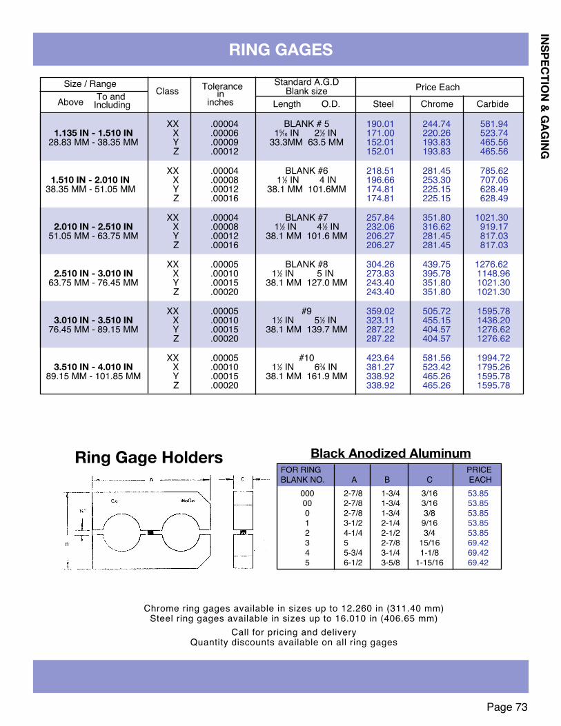
Page 73
XX .00004 BLANK # 5 190.01 244.74 581.941.135 IN - 1.510 IN X .00006 15⁄16 IN 21⁄2 IN 171.00 220.26 523.74
28.83 MM - 38.35 MM Y .00009 33.3MM 63.5 MM 152.01 193.83 465.56Z .00012 152.01 193.83 465.56
XX .00004 BLANK #6 218.51 281.45 785.621.510 IN - 2.010 IN X .00008 11⁄2 IN 4 IN 196.66 253.30 707.06
38.35 MM - 51.05 MM Y .00012 38.1 MM 101.6MM 174.81 225.15 628.49Z .00016 174.81 225.15 628.49
XX .00004 BLANK #7 257.84 351.80 1021.302.010 IN - 2.510 IN X .00008 11⁄2 IN 41⁄2 IN 232.06 316.62 919.17
51.05 MM - 63.75 MM Y .00012 38.1 MM 101.6 MM 206.27 281.45 817.03Z .00016 206.27 281.45 817.03
XX .00005 BLANK #8 304.26 439.75 1276.622.510 IN - 3.010 IN X .00010 11⁄2 IN 5 IN 273.83 395.78 1148.96
63.75 MM - 76.45 MM Y .00015 38.1 MM 127.0 MM 243.40 351.80 1021.30Z .00020 243.40 351.80 1021.30
XX .00005 #9 359.02 505.72 1595.783.010 IN - 3.510 IN X .00010 11⁄2 IN 51⁄2 IN 323.11 455.15 1436.20
76.45 MM - 89.15 MM Y .00015 38.1 MM 139.7 MM 287.22 404.57 1276.62Z .00020 287.22 404.57 1276.62
XX .00005 #10 423.64 581.56 1994.723.510 IN - 4.010 IN X .00010 11⁄2 IN 63⁄8 IN 381.27 523.42 1795.26
89.15 MM - 101.85 MM Y .00015 38.1 MM 161.9 MM 338.92 465.26 1595.78Z .00020 338.92 465.26 1595.78
Size / Range Tolerance Standard A.G.D Price EachTo and Class in Blank size
Above Including inches Length O.D. Steel Chrome Carbide
RING GAGES
Chrome ring gages available in sizes up to 12.260 in (311.40 mm)Steel ring gages available in sizes up to 16.010 in (406.65 mm)
Call for pricing and deliveryQuantity discounts available on all ring gages
INSPECTION & GAGING
Ring Gage Holders Black Anodized AluminumFOR RING PRICEBLANK NO. A B C EACH
000 2-7/8 1-3/4 3/16 53.8500 2-7/8 1-3/4 3/16 53.850 2-7/8 1-3/4 3/8 53.851 3-1/2 2-1/4 9/16 53.852 4-1/4 2-1/2 3/4 53.853 5 2-7/8 15/16 69.424 5-3/4 3-1/4 1-1/8 69.425 6-1/2 3-5/8 1-15/16 69.42
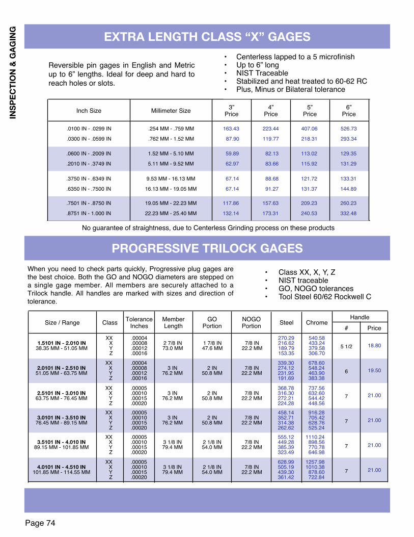
Page 74
INSP
ECTI
ON &
GAG
ING EXTRA LENGTH CLASS “X” GAGES
PROGRESSIVE TRILOCk GAGES
XX .00004 270.29 540.581.5101 IN - 2.010 IN X .00008 2 7/8 IN 1 7/8 IN 7/8 IN 216.62 433.24
38.35 MM - 51.05 MM Y .00012 73.0 MM 47.6 MM 22.2 MM 189.79 379.58Z .00016 153.35 306.70
XX .00004 339.30 678.602.0101 IN - 2.510 IN X .00008 3 IN 2 IN 7/8 IN 274.12 548.24
51.05 MM - 63.75 MM Y .00012 76.2 MM 50.8 MM 22.2 MM 231.95 463.90Z .00016 191.69 383.38
XX .00005 368.78 737.562.5101 IN - 3.010 IN X .00010 3 IN 2 IN 7/8 IN 316.30 632.60
63.75 MM - 76.45 MM Y .00015 76.2 MM 50.8 MM 22.2 MM 272.21 544.42Z .00020 224.28 448.56
XX .00005 458.14 916.283.0101 IN - 3.510 IN X .00010 3 IN 2 IN 7/8 IN 352.71 705.42
76.45 MM - 89.15 MM Y .00015 76.2 MM 50.8 MM 22.2 MM 314.38 628.76Z .00020 262.62 525.24
XX .00005 555.12 1110.243.5101 IN - 4.010 IN X .00010 3 1/8 IN 2 1/8 IN 7/8 IN 449.28 898.56
89.15 MM - 101.85 MM Y .00015 79.4 MM 54.0 MM 22.2 MM 385.39 770.78Z .00020 323.49 646.98
XX .00005 628.99 1257.984.0101 IN - 4.510 IN X .00010 3 1/8 IN 2 1/8 IN 7/8 IN 505.19 1010.38
101.85 MM - 114.55 MM Y .00015 79.4 MM 54.0 MM 22.2 MM 439.30 878.60Z .00020 361.42 722.84
ClassSize / Range ToleranceInches
MemberLength
GOPortion
NOGOPortion Steel Chrome
Handle
5 1/2
6
7
7
7
7
18.80
19.50
21.00
21.00
21.00
21.00
Price#
When you need to check parts quickly, Progressive plug gages arethe best choice. Both the GO and NOGO diameters are stepped ona single gage member. All members are securely attached to aTrilock handle. All handles are marked with sizes and direction oftolerance.
• Class XX, X, Y, Z• NIST traceable• GO, NOGO tolerances• Tool Steel 60/62 Rockwell C
.0100 IN - .0299 IN .254 MM - .759 MM 163.43 223.44 407.06 526.73
.0300 IN - .0599 IN .762 MM - 1.52 MM 87.90 119.77 218.31 293.34
.0600 IN - .2009 IN 1.52 MM - 5.10 MM 59.89 82.13 113.02 129.35
.2010 IN - .3749 IN 5.11 MM - 9.52 MM 62.97 83.66 115.92 131.29
.3750 IN - .6349 IN 9.53 MM - 16.13 MM 67.14 88.68 121.72 133.31
.6350 IN - .7500 IN 16.13 MM - 19.05 MM 67.14 91.27 131.37 144.89
.7501 IN - .8750 IN 19.05 MM - 22.23 MM 117.86 157.63 209.23 260.23
.8751 IN - 1.000 IN 22.23 MM - 25.40 MM 132.14 173.31 240.53 332.48
Millimeter SizeInch Size 3”Price
4”Price
5”Price
6”Price
Reversible pin gages in English and Metricup to 6” lengths. Ideal for deep and hard toreach holes or slots.
No guarantee of straightness, due to Centerless Grinding process on these products
• Centerless lapped to a 5 microfinish• Up to 6” long• NIST Traceable• Stabilized and heat treated to 60-62 RC• Plus, Minus or Bilateral tolerance

Page 75
QUICk ADJUST
INSPECTION & GAGING
ADJUSTABLE V-BLOCk FOR COMPARATOR USE
Model QSS-3
Before Adjustment After Adjustment
SPECIFICATIONS:Height: 2-1/2"Height/Float Capacity: 9/32Width: 1-1/2"Length: 4-1/4"Weight: 2 lbs.Material: Carbon SteelFinish:NaturalGroove Dimensions:1. .172 Wide X .078 Deep2. .123 Wide X .054 Deep3. Center Groove .430 Wide X .212
Deep
QSS-3 $293.252-1/2" HighT-base and base lock to fit most comparator tables.Six Holes:1/8, 5/32, 3/16, 7/32, 1/4, 9/32Depth of Hole: 13/16
OPTIONALCLAMP $9.25
• QUICK ADJUST allows machinists and inspectors to quickly line up components.• QUICK ADJUST eliminates shimming time, and maximizes inspection time.• QUICK ADJUST speeds up the inspection of parts that are unbalanced or top heavy.• QUICK ADJUST actually encourages operators to measure because of the easy set up of components.• RESULT: More inspection, improved quality• Fine and smooth adjustment with large adjusting screw.• 2-pins in floating V assures smooth adjustment and accuracy.• Can be customized to your specifications.
U.S. Patent #5,220,730Granted June 22, 1993.
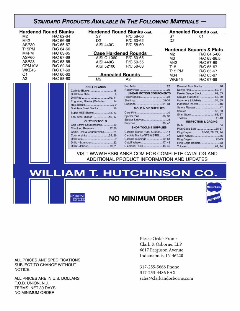
WILLIAM T. HUTCHINSON CO.
NO MINIMUM ORDER
ALL PRICES AND SPECIFICATIONSSUBJECT TO CHANGE WITHOUTNOTICE.
ALL PRICES ARE IN U.S. DOLLARSF.O.B. UNION, N.J. TERMS: NET 30 DAYSNO MINIMUM ORDER
DRILL BLANkSCarbide Blanks...............................15Drill Blank Sets .................................9Drill Rod ...................................10, 11Engraving Blanks (Carbide) ...........14HSS Blanks...................................2-9Stainless Steel Blanks....................18Super HSS Blanks ...................12, 13Tool Steel Blanks .....................16, 17
CUTTING TOOLSCap Screw Counterbores...............30Chucking Reamers ...................27-29Comb. Drill & Countersinks ............24Countersinks ............................25, 26Drill Sets ...........................................9Drills - Extension ............................22Drills - Jobber ............................19-21
End Mills.........................................23Rotary Files ....................................26
LINEAR MOTION COMPONENTSPillow Blocks ..................................31Shafting.....................................32-34Supports ...................................31, 34
MOLD & DIE SUPPLIESCore Pins .......................................39Ejector Pins ..............................36, 37Ejector Sleeves ..............................35Punches ...................................38, 40
SHOP TOOLS & SUPPLIESCarbide Blanks-1000 & 2000 .........44Carbide Blanks-STB & STBL .........45Carbide Bushings.....................60, 61Cutoff Wheels...........................47, 48Diamond Tools .........................48, 49
Dovetail Tool Blanks ......................46Dowel Pins ...............................50, 51Feeler Gauge Stock .................62, 63Ground Flat Stock ....................58, 59Hammers & Mallets ..................54, 55Indexable Inserts ............................46Safety Flanges ...............................47Screws .....................................52, 53Shim Stock ...............................56, 57Toolbits .....................................41-43
INSPECTION & GAGINGBalls ..............................................64Plug Gage Sets.........................65-67Plug Gages .............65-68, 70, 71, 74Quick Adjust ...................................75Ring Gages ...............................72-73Ring Gage Holders.........................73Trilocks.....................................69, 74
STANDARD PRODUCTS AVAILABLE IN THE FOLLOWING MATERIALS —Hardened Round Blanks
M2 R/C 62-64M42 R/C 66-68ASP30 R/C 65-67T15PM R/C 64-66M4PM R/C 63-65ASP60 R/C 67-69ASP23 R/C 63-65CPM10V R/C 62-64WKE45 R/C 67-69O1 R/C 60-62A2 R/C 58-60
Hardened Round Blanks cont.S7 R/C 58-60D2 R/C 60-62AISI 440C R/C 58-60
Case Hardened RoundsAISI C-1060 R/C 60-65AISI 440C R/C 50-55AISI 52100 R/C 58-63
Annealed RoundsM2 A2
Annealed Rounds cont.S7 01D2
Hardened Squares & FlatsM2 R/C 64.5-66M3 R/C 65-66.5M42 R/C 67-69T15 R/C 65-67T15 PM R/C 65-67M34 R/C 65-67WKE45 R/C 67-69
]q t
VISIT WWW.HSSBLANKS.COM FOR COMPLETE CATALOG ANDADDITIONAL PRODUCT INFORMATION AND UPDATES
Please Order From:Clark & Osborne, LLP6617 Ferguson AvenueIndianapolis, IN 46220
317-255-5668 Phone317-253-4486 [email protected]