Embed Size (px)
Citation preview

S020
p. 1/12www.burkert.com
Environment - Approvals
Ambient temperature Temperature limits may depend on the sensor. Please refer to appropriate instruction manual or datasheet for more details.
Approval / Certificate
on request
3.1 Certificate; 2.2 Certificate; Rugosity Certificate;FDA (with EPDM seal) - stainless steel fitting only
Type 8205/8206
Digital pH/ ORP
transmitter
INSERTION fitting for flow measurement or analysis
The fitting can be used to connect any
INSERTION device for a measurement in
the pipe.
i.e. sensors, indicators, transmitters and
controllers for flow, pH, ORP and
Conductivity measurement.
General data
Pipe diameter DN 06 up to DN 4001)
Fitting port connection
Metal Plastic
Internal or external thread, weld ends, Tri-Clamp®, flangeTrue union, spigot and external thread
Materials
Seal Body & adaptation part
FKM or EPDMBrass (CuZn39Pb2) & stainless steel (316L -1.4404),all stainless steel (316L -1.4404) or all PVC, PP, PVDF, PE
Type 8020
Flow sensor
Type 8024
Flow indicator
Type 8025
Digital flow
transmitter
Type S020 can be combined with...
Type 8045/8041
Electromagnetic
flow transmitter
• Universal fitting for INSERTION sensors, transmitters, batch controllers in pure, aggressive or contamined liquids
• Large range of process connections: DN 06 to 400 in PVC, PP, PVDF, PE, stainless steel, brass
• Electronics available for - Indication, Monitoring, Transmitting - On/Off control, Batch control
Medium data
Fluid temperature
(160 °C max.)
Temperature limits may depend on the sensor. Please refer to appropriate instruction manual or datasheet for more details.
Fluid pressure (max.)
Metal Plastic
PN 16PN 10 Pressure limits may depend on the sensor. Please refer to appropriate instruction manual or datasheet for more details.
Type 8225
Digital conductivity
transmitter
1) Combination between fitting and sensors is sometimes restricted to some DN (see diagram: combining the S020 with sensors on next page)
Tri-Clamp® is a registered Trademark of Alfa Laval Inc.

S020
p. 2/12
A (Type 8226)
A (Type 8223)
-10 +10 +30 +50 +70 +90 +1100
2
1
3
4
5
6
7
PVC (PN 6)
PP (PN 6)
PVDF (PN 6)
+130
Metal
A (Type 8205/8206)
PVDF
PVC + PP
A (Type 8041, 8045 PVDF sensor)
Availab
le f
itti
ng
DN T-fitting S020
Welding tab S020
Fusion spigot S020
Screw-on S020For flow measurement
Saddle S020For flow measurement
Flow rate measurement
8020 - 8024 - 8025 - 8041 - 8045
* see Note on each fitting dimensions diagram
pH or ORP measurement
8200 - 8205 - 8206 compact version
8205 - 8206 remote version
** Use only with true union fitting acc. to DIN/ISO
in analysis version
Conductivity measurement
8220 - 8223 - 8225 -8226
** Use only with true union fitting acc. to DIN/ISO
in analysis version
Combining the S020 with sensors for flow rate, pH or ORP, conductivity measurement
DN 06 DN200 DN400
DN350
DN65
DN50 DN200
DN100
DN 06
DN50
Short sensor version Long sensor versionShort or long*
DN100 DN400
DN400DN65
DN 15 DN200
DN 15 DN200DN32**
DN 15 DN200DN32
**
For further details about the various combination possibilities (sensor and fitting), please consult sensor related datasheet.
Pressure / temperature chart
Pressure and temperature limits depend on the sensor. Please refer to
corresponding sensor datasheet for more details.
Fittings with
• Type 8041 - 8045 PVDF flow sensor/transmitter
• Type 8205 - 8206 - 8223 - 8226 analyse sensor/transmitter
Pressure [bar]
Temperature [°C]
DN15only 8041/8045
A (Typ 8220, 8225)
10
9
8
7
6
5
4
3
2
1
0-10 +10 +30 +50 +70 +90
PVDF
PVDF (PN10)
PVC (PN10)
PP (PN10)
PVC + PP
Metall
A (Typ 8020, 8024, 8025)
10
9
8
7
6
5
4
3
2
1
0-10 +10 +30 +50 +70 +90 +110
PVDF
PVDF (PN10)
PVC (PN10)
PP (PN10)
PVC + PP
+130
16
15
14
13
12
11
Metal (PN16)
A (Type 8045 - Stainless steel sensor)
+150
A (Type 8041 - Stainless steel sensor)
Fittings with
• Type 8041 - 8045 stainless steel flow sensor/transmitter
Fittings with
• Type 8020 - 8024 - 8025 flow sensor/transmitter
• Type 8220 - 8225 analyse sensor/transmitter
Pressure [bar]
Temperature [°C]
Pressure [bar]
Temperature [°C]

S020
p. 3/12
Selection fitting / pipe size
Flow rate
Flow velocity
m3/h
0.1 0.3 0.5 1 3 5 100.01
0.02
0.05
0.1
0.2
0.5
1
2
5
10
20
50
100
200
0.2
0.5
1
2
5
10
20
50
100
200
500
1000
2000
3000
l/min
0.3 0.5 1 3 5 10 30
m/s
fps
US gpm
0.05
0.1
0.2
0.5
1
2
5
10
20
50
100
200
500
1000
DN 65
DN 50 (DN65)*
DN 40 (DN50)*
DN 32 (DN40)*
DN 25 (DN32)*
DN 20 (DN25)*
DN 15 (DN15 or DN20)*
DN 08
DN 06
500
1000
2000
2000
5000
10000
500020000
5000
10000
20000
30000
50000
100000
DN 400
DN 350
DN 300
DN 250
DN 200
DN 150
DN 125
DN 100
DN 80
Example:
- Specification of nominal flow: 10 m3/h
- Ideal flow velocity: 2...3 m/s
- For these specifications, the diagram indicates a pipe size of DN40 [or DN50 for (*) mentioned fittings]
* for following fittings:
- with external threads acc. to SMS 1145
- with weld-ends acc. to SMS 3008, BS 4825 / ASME BPE or DIN 11850 Series 2
- TriClamp® acc. to SMS 3017 / ISO 2852, BS 4825 / ASME BPE or DIN 32676
Tri-Clamp® is a registered Trademark of Alfa Laval Inc.

S020
p. 4/12
Installation
Flow measurement:
Minimum straight upstream and downstream distances must be observed. According to the pipe’s design, necessary distances can be bigger or use a
flow conditioner to obtain the best accuracy. For more information, please refer to EN ISO 5167-1.
EN ISO 5167-1 prescribes the straight inlet and outlet distances that must be complied with when installing fittings in pipe lines in order to achieve
calm flow conditions. The most important layouts that could lead to turbulence in the flow are shown below, together with the associated prescribed
minimum inlet and outlet distances. These ensure calm, problem-free measurement conditions at the measurement point.
The flow rate sensor can be installed in either horizontal or vertical pipes.
Analysis measurement:
For pH and ORP measurements, we recommended a “U”-form bypass installation to ensure
that the electrode is maintained in a wet condition and enable the customer to calibrate the
unit without stopping the whole process or to use the special designed measuring chamber.
The specially designed measuring chamber enables to install all pH-, ORP-, conductivity-
transmitters or electrodes in all pipe systems, either directly in the main stream or in a
by-pass line. Additionally it enables to keep the electrode always wet and isolates it easily
from the main stream for calibration purposes.
Pressure and temperature ratings must be respected according to the selected fitting material.
The suitable pipe size is selected using the diagram Flow / Velocity / DN.
50 x DN 5 x DN
40 x DN 5 x DN
25 x DN 5 x DN
20 x DN 5 x DN
18 x DN 5 x DN
15 x DN 5 x DN
Regulating valve
2 x 90° elbow joint
3 dimensional
2 x 90° elbow joint
90° elbow joint
or T-piece
Extension
Reduction
DN = orifice Fluid direction -->
Correct Incorrect
CorrectIncorrect
IncorrectCorrect
Correct
Incorrect

S020
p. 5/12
A
D
P
A
L
D
P
A
LD
P
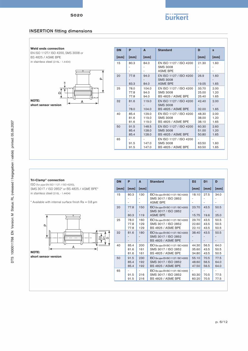
INSERTION fitting dimensions
Internal thread connection
G, NPT or Rc
in stainless steel (316L - 1.4404) or
brass (CuZn39Pb2)
DN
[mm]
P
[mm]
A
[mm]
D
[inch]
L
[mm]
15 80.3 84.0 G 1/2 NPT 1/2 Rc 1/2
16.017.015.0
20 77.8 94.0 G 3/4 NPT 3/4 Rc 3/4
17.018.316.3
25 78.0 104.0 G 1 NPT 1 Rc 1
23.518.018.0
32 81.6 119.0 G 1 1/4 NPT 1 1/4 Rc 1 1/4
23.521.021.0
40 85.4 129.0 G 1 1/2 NPT 1 1/2 Rc 1 1/2
23.520.019.0
50 91.5 148.5 G 2 NPT 2 Rc 2
27.524.024.0
External thread connection
G,
in stainless steel (316L - 1.4404),
brass (CuZn39Pb2),
PVC (only DN 6 and DN 8)
DN
[mm]
P
[mm]
A
[mm]
D
[inch] [mm]
L
[mm]
06 75.3 90.0 G 1/2 - 14.0
08 75.3 90.0 G 1/2 - 14.0
15 80.3 84.0 G 3/4 - 11.5
20 77.8 94.0 G 1 - 13.5
25 78.0 104.0 G 1 1/4 - 14.0
32 81.6 119.0 G 1 1/2 - 18.0
40 85.4 129.0 - M 55 x 2 19.0
50 91.5 148.5 - M 64 x 2 20.0
NOTE:
short sensor version
NOTE:
short sensor version
External thread connection
SMS 1145,
in stainless steel (316L - 1.4404)
DN
[mm]
P
[mm]
A
[mm]
D
25 77.8 130 Rd 40 x 1/6”
40 81.6 164 Rd 60 x 1/6”
50 85.4 173 Rd 70 x 1/6”
NOTE:
short sensor version
S020
p. 6/12
PA
D
s
INSERTION fitting dimensions
Weld ends connection
EN ISO 1127/ ISO 4200, SMS 3008 or
BS 4825 / ASME BPE
in stainless steel (316L - 1.4404)
DN
[mm]
P
[mm]
A
[mm]
Standard D
[mm]
s
[mm]
15 80.3--
84.0--
EN ISO 1127 / ISO 4200SMS 3008ASME BPE
21.30 --
1.60--
20 77.8-83.3
94.0-84.0
EN ISO 1127 / ISO 4200SMS 3008ASME BPE
26.9-19.05
1.60-1.65
25 78.077.877.8
104.094.094.0
EN ISO 1127 / ISO 4200SMS 3008BS 4825 / ASME BPE
33.7025.0025.40
2.001.201.65
32 81.6-78.0
119.0-104.0
EN ISO 1127 / ISO 4200SMS 3008BS 4825 / ASME BPE
42.40-32.00
2.00-1.65
40 85.481.681.6
129.0119.0119.0
EN ISO 1127 / ISO 4200SMS 3008BS 4825 / ASME BPE
48.3038.0038.10
2.001.201.65
50 91.585.485.4
148.5128.0128.0
EN ISO 1127 / ISO 4200SMS 3008BS 4825 / ASME BPE
60.3051.0050.80
2.601.201.65
65 -91.591.5
-147.0147.0
EN ISO 1127 / ISO 4200SMS 3008BS 4825 / ASME BPE
-63.5063.50
-1.601.65
Tri-Clamp® connection
ISO (for pipe EN ISO 1127 / ISO 4200),
SMS 3017 / ISO 2852* or BS 4825 / ASME BPE*
in stainless steel (316L - 1.4404)
* Available with internal surface finish Ra = 0.8 μm
NOTE:
short sensor version
NOTE:
short sensor version
DN
[mm]
P
[mm]
A
[mm]
Standard D2
[mm]
D1
[mm]
D
[mm]
15 80.3--
130--
ISO (for pipe EN ISO 1127 / ISO 4200)
SMS 3017 / ISO 2852ASME BPE
18.10--
27.5--
34.0--
20 77.8-80.3
150-119
ISO (for pipe EN ISO 1127 / ISO 4200)
SMS 3017 / ISO 2852ASME BPE
23.70-15.75
43.5-19.6
50.5-25.0
25 78.077.877.8
160129129
ISO (for pipe EN ISO 1127 / ISO 4200)
SMS 3017 / ISO 2852BS 4825 / ASME BPE
29.7022.6022.10
43.543.543.5
50.550.550.5
32 81.6--
180--
ISO (for pipe EN ISO 1127 / ISO 4200)
SMS 3017 / ISO 2852BS 4825 / ASME BPE
38.40--
43.5--
50.5--
40 85.481.681.6
200161161
ISO (for pipe EN ISO 1127 / ISO 4200)
SMS 3017 / ISO 2852BS 4825 / ASME BPE
44.3035.6034.80
56.543.543.5
64.050.550.5
50 91.585.485.4
230192192
ISO (for pipe EN ISO 1127 / ISO 4200)
SMS 3017 / ISO 2852BS 4825 / ASME BPE
55.1048.6047.50
70.556.556.5
77.564.064.0
65 -91.591.5
-216216
ISO (for pipe EN ISO 1127 / ISO 4200)
SMS 3017 / ISO 2852BS 4825 / ASME BPE
-60.3060.20
-70.570.5
-77.577.5
DD2
D1
P
A

S020
p. 7/12
A
D D1
D2
Z
LP
INSERTION fitting dimensions
Flange connection
DIN 2633 (ISO PN16), ANSI B16-5-1988 or JIS 10 K
in stainless steel (316L - 1.4404)
DN
[mm]
P
[mm]
A
[mm]
Standard L
[mm]
Z
[mm]
D2
[mm]
D1
[mm]
D
[mm]
15 80.3 130130152
DINANSIJIS
23.5 4x14.04x15.84x15.0
45.034.951.0
65.060.370.0
95.089.095.0
20 77.8 150150178
DINANSIJIS
28.5 4x14.04x15.84x15.0
58.042.956.0
75.069.875.0
105.099.0100.0
25 78.0 160160216
DINANSIJIS
28.5 4x14.04x15.84x19.0
68.050.867.0
85.079.490.0
115.0108.0125.0
32 81.6 180180229
DINANSIJIS
31.0 4x18.04x15.84x19.0
78.063.576.0
100.088.9100.0
140.0117.0135.0
40 85.4 200200241
DINANSIJIS
36.0 4x18.04x15.84x19.0
88.073.081.0
110.098.4105.0
150.0127.0140.0
50 91.5 230230267
DINANSIJIS
41.0 4x18.04x19.04x19.0
102.092.196.0
125.0120.6120.0
165.0152.0155.0
True union connection
DIN 8063, ASTM D 1785/76 or JIS K in PVC,
DIN 16962 in PP or
ISO 10931 in PVDF
NOTE:
short sensor version
NOTE:
short sensor version
DN
[mm]
P
[mm]
A
[mm]
Standard A1
[mm]
A2
[mm]
D
[mm]
D1
[mm]
15
15*
80.480.480.481.4
128.0130.0129.0148.0
DIN / ISOASTMJISDIN / ISO
969696116
909090110
20.0021.3018.4020.00
43434374
20
20*
77.877.877.881.4
144.0145.6145.0154.0
DIN / ISOASTMJISDIN / ISO
106106106116
100100100110
25.0026.7026.4525.00
53535374
25
25*
78.078.078.081.4
160.0161.4161.0160.0
DIN / ISOASTMJISDIN / ISO
116116116116
110110110110
32.0033.4032.5532.00
60606074
32 81.4 168.0170.0169.0
DIN / ISOASTMJIS
116 110 40.0042.2038.60
74
40 85.2 188.0190.2190.0
DIN / ISOASTMJIS
127 120 50.0048.3048.70
83
50 91.5 212.0213.6213.0
DIN / ISOASTMJIS
136 130 63.0060.3060.80
103
AA1A2
P
D D1
* Analysis version

S020
p. 8/12
Saddle
in PP
Body material: PP/PVC
Seal material: EPDM
NOTE:
long sensor version
P
DD1
H
Welding tab with radius
in stainless steel (316L - 1.4404)
NOTE:
sensor version:
- short for DN 50 - DN 200
- long for DN 250 - DN 350
Spigot connection
DIN 8063 in PVC,
DIN 16962 in PP or
ISO 10931 in PVDF
NOTE:
short sensor version
DN
[mm]
P
[mm]
A
[mm]
Standard L
[mm]
D
[mm]
H
[mm]
15 80.4 908585
DIN 8063DIN 16962ISO 10931
16.514.014.0
20 17.5
20 77.8 1009292
DIN 8063DIN 16962ISO 10931
20.016.016.0
25 17.5
25 78.0 1109595
DIN 8063DIN 16962ISO 10931
23.018.018.0
32 21.5
32 81.4 110100100
DIN 8063DIN 16962ISO 10931
27.520.020.0
40 27.5
40 85.2 120106106
DIN 8063DIN 16962ISO 10931
30.023.023.0
50 31.5
50 91.5 130110110
DIN 8063DIN 16962ISO 10931
37.027.027.0
63 39.5
PH
D
LA
INSERTION fitting dimensions
DN
[mm]
P
[mm]
H
[mm]
D
[mm]
D1
[mm]
50 116.0 155 116 63
65 115.0 160 129 75
80 119.0 171 144 90
100 124.0 187 166 110
110 120.0 191 181 125
125 127.0 205 196 140
150 137.0 225 216 160
180 161.0 271 266 200
200 173.0 291 290 225
DN
[mm]
A
[mm]
B
[mm]
R
[mm]
50 56.6 61.6 30.2
65 54.5 58.6 36.7
80 53.1 56.4 44.5
100 50.7 53.2 57.2
125 48.2 50.3 70.7
150 45.7 47.4 84.2
200 41.0 42.3 109.6
250 73.6 74.7 136.6
300 67.8 68.7 162.0
350 63.9 64.7 177.8
B
RR0.5
A +
0.1

S020
p. 9/12
Fusion spigot
in PE, PP or PVDF
NOTE:
sensor version:
- short for DN 65 - DN 100
- long for DN 150 - DN 400
INSERTION fitting dimensions
DN
[mm]
H
[mm]
Materials
[mm]
H1
[mm]
H2
[mm]
65 72.5 PEPPPVDF
13.013.010.4
---
80 72.5 PEPPPVDF
15.615.612.5
---
100 72.5 PEPPPVDF
19.019.015.2
5.05.06
125 102.0 PEPPPVDF
24.2--
8.0--
150 102.0 PEPPPVDF
27.727.7-
10.010.0-
200 102.0 PEPPPVDF
38.938.9-
16.016.0-
250 102.0 PEPPPVDF
48.448.4-
21.021.0-
300 102.0 PEPPPVDF
54.554.5-
24.024.0-
350 102.0 PEPPPVDF
61.361.3-
28.028.0-
400 102.0 PEPPPVDF
69.1--
31.5--
HH
1
ø39
H2
Screw-on
DN 100 to 400
in PVC, PP, PE
NOTE:
long sensor version
Measuring chamber (only for analysis sensor / transmitter version)
ø 60.3
ø 60
ø 33.6
ø 27
41
2.70
80.2
17.6
62.6
NOTE:
Materials: stainless steel 316L
Pipe connection: G 1/2”
G1-1/2"
ø27.6ø 45ø 49
7393
11.5
90°R4 (4x)
3
45
16.2

S020
p. 10/12
Po
rt
co
nn
ecti
on
Se
al
Sta
nd
ard
Ite
m n
o.
DN
06 - 1/2
”
Ite
m n
o.
DN
08 - 1
/2”
Ite
m n
o.
DN
15
Ite
m n
o.
DN
20
Ite
m n
o.
DN
25
Ite
m n
o.
DN
32
Ite
m n
o.
DN
40
Ite
m n
o.
DN
50
Ite
m n
o.
DN
65
Brass body & stainless steel adaptation part - T-fitting - Temperature max. 160°C, PN16
Internal FKM G - - 428 712 428 713 428 714 428 715 428 716 428 717 -
thread NPT - - 428 718 428 719 428 720 428 721 428 722 428 723 -
Rc (ISO7) - - 428 724 428 725 428 726 428 727 428 728 428 729 -
External thread FKM G - - 428 730 428 731 428 732 428 733 428 734 428 735 -
Stainless steel body & stainless steel adaptation part - T-fitting - Temperature max. 160°C, PN16
Internal FKM G - - 428 736 428 737 428 738 428 739 428 740 428 741 -
thread NPT - - 428 742 428 743 428 744 428 745 428 746 428 747 -
Rc (ISO7) - - 428 748 428 749 428 750 428 751 428 752 428 753 -
External thread FKM G 552 434 552 432 428 754 428 755 428 756 428 757 428 758 428 759 -
EPDM SMS 1145 - - - - 443 317 - 443 318 443 319 -
Weld ends FKM EN ISO 1127 / ISO 4200 - - 428 760 428 761 428 762 428 763 428 764 428 765 -
EPDM SMS 3008 - - - - 443 309 - 443 310 443 311 443 944
BS 4825/ ASME BPE - - - 443 7341) 443 735 443 736 443 942 443 943 443 944
Tri-Clamp® FKM ISO (for pipe EN ISO 1127/ISO4200) - - 428 766 428 767 428 768 428 769 428 770 428 771 -
EPDM SMS 3017 / ISO 2852 - - - - 443 313 - 443 314 443 315 443 969
SMS 3017 / ISO 2852* - - - - 443 957 - 443 958 443 959 443 974
BS 4825 / ASME BPE - - - 443 9651) 443 966 - 443 967 443 968 443 969
BS 4825 / ASME BPE* - - - 443 970 443 971 - 443 972 443 973 443 974
Flange FKM DIN 2633 - - 428 772 428 773 428 774 428 775 428 776 428 777 -
ANSI B16-5-1988 - - 428 778 428 779 428 780 428 781 428 782 428 783 -
JIS 10K - - 431 053 431 054 431 055 431 056 431 057 431 058 -
PVC & PVC adaptation part - T-fitting - Temperature max. 50°C, PN10
True union FKM DIN 8063 - - 428 670 428 671 428 672 428 673 428 674 428 675 -
ASTM D 1785/76 - - 428 682 428 683 428 684 428 685 428 686 428 687 -
JIS K - - 429 078 429 079 429 080 429 081 429 082 429 083 -
Spigot FKM DIN 8063 - - 428 676 428 677 428 678 428 679 428 680 428 681 -
External thread FKM G 552 561 550 062 - - - - - - -
Analysis True union FKM DIN 8063 - - 430 837 430 838 430 839 428 673 428 674 428 675 -
PP & PP adaptation part - T-fitting - Temperature max. 80°C, PN10
True union FKM DIN 16962 - - 428 688 428 689 428 690 428 691 428 692 428 693 -
Spigot FKM DIN 16962 - - 428 694 428 695 428 696 428 697 428 698 428 699 -
Analysis True union FKM DIN 16962 - - 430 840 430 841 430 842 428 691 428 692 428 693 -
PVDF & PVDF adaptation part - T-fitting - Temperature max. 100°C, PN10
True union FKM ISO 10931 - - 428 700 428 701 428 702 428 703 428 704 428 705 -
Spigot FKM ISO 10931 - - 428 706 428 707 428 708 428 709 428 710 428 711 -
Analysis True union FKM ISO 10931 - - 430 843 430 844 430 845 428 703 428 704 428 705 -
Ordering chart for fitting S020
DN 6 to DN 65
* internal surface finish Ra = 0.8 μm1) DN 20 only available in ASME BPE

S020
p. 11/12
Po
rt
co
nn
ecti
on
Ite
m n
o.
DN
50
Ite
m n
o.
DN
65
Ite
m n
o.
DN
80
Ite
m n
o.
DN
100
Ite
m n
o.
DN
125
Ite
m n
o.
DN
150
Ite
m n
o.
DN
200
Ite
m n
o.
DN
250
Ite
m n
o.
DN
300
Ite
m n
o.
DN
350
Ite
m n
o.
DN
400
Stainless steel - welding tab with radius - Temperature max. 160°C, PN16
Welding tabs 418 111 418 112 418 113 418 114 418 115 418 116 418 117 418 756 420 070 416 637 -
PVC - Screw-on fitting - Temperature max. 50°C, PN10
Screw-on - - - 418 170 418 170 418 170 418 170 - - - -
PVDF - Fusion spigot - Temperature max. 100°C, PN10
Fusion spigot - 418 658 418 659 418 660 - - - - - - -
Analysis Fusion spigot - 418 660 418 660 418 660 418 660 418 660 418 660 - - - -
PE - Fusion spigot or screw-on fitting - Temperature max. 70°C, PN10
Fusion spigot - 418 642 418 643 418 644 418 590 418 645 418 646 418 647 418 648 418 649 418 598
Screw-on - - - 436 489 436 489 436 489 436 489 436 489 436 489 436 489 436 489
Analysis Fusion spigot - 418 644 418 644 418 644 418 644 418 644 418 644 - - - -
PP - Fusion spigot or screw-on fitting - Temperature max. 80°C, PN10
Fusion spigot - 418 650 418 651 418 652 - 418 653 418 654 418 655 418 656 418 657 -
Screw-on - - - 436 488 436 488 436 488 436 488 436 488 436 488 436 488 436 488
Analysis Fusion spigot - 418 652 418 652 418 652 418 652 418 652 418 652 - - - -
Ordering chart for fitting S020
DN 50 to DN 400
Po
rt
co
nn
ecti
on
Se
al
Ite
m n
o.
DN
50
Ite
m n
o.
DN
65
Ite
m n
o.
DN
80
Ite
m n
o.
DN
100
Ite
m n
o.
DN
110
Ite
m n
o.
DN
125
Ite
m n
o.
DN
150
Ite
m n
o.
DN
180
Ite
m n
o.
DN
200
PP - Saddle - Temperature max. 80°C, PN10 (for PVC or PP pipe)
Saddle FKM 425 138 425 139 425 140 425 141 425 142 425 143 425 144 433 873 425 416
Ordering chart for accessories / spare parts (other versions on request)
De
scri
pti
on
Ite
m n
o.
Adaptation part (DN 06 to 65)
Stainless steel 555 484
PVC 419 098
PP 419 808
PVDF 419 809
Approvals / Certificates
3.1 certificate 440 790
2.2 certificate 440 789
Rugosity certificate 444 898
FDA approval 449 788
Stopper with
ring, union nut
and O-ring
Adaptation
part
O-ring set
De
scri
pti
on
Ite
m n
o.
O-ring set (DN 06 to 65)
FKM - for metal fitting (5 units) 428 971
EPDM - for metal fitting (5 units) 428 972
FKM - for plastic fitting (1 unit) 427 423
EPDM - for plastic fitting (1 unit) 427 424
Stopper with ring, union nut and O-ring
Stainless steel 438 755
PVC 438 754
PP 627 614
Measuring chamber
Stainless steel1) 316L (1.4404) 553 6111) other material on request

S020
p. 12/12
Re
mo
te e
lectr
on
ics
Co
mp
act
ele
ctr
on
ics
Se
nso
rF
itti
ng
Interconnection possibilities with the S020
To find your nearest Bürkert facility, click on the orange box → www.burkert .com
In case of special application conditions,please consult for advice.
We reserve the right to make technical changes without notice. 0705/5_EU-en_00891872
Type S020 -
Metal or plastic
Type 8025 -
Flow transmitter /
batch controller
Wall- or panel- mounted
output:
4 - 20 mA
Relay
Pulse
Type 8205 -
pH transmitter /
controller
Wall- or panel-
mounted
Measuring
chamber
Type 8020 -
Flow sensor
output:
Pulse or
Frequency
Type 8041 -
Magmeter
output:
Frequency or
4-20 mA
Type 8200 -
pH / ORP
sensor
Type 8223 -
Inductive
conductivity
sensor
output:
4-20 mA
Type 8220 -
Resistive
conductivity
sensor
Type 8024 -
Flow indicator
Type 8025 -
Flow transmitter/
batch controller
output:
4-20 mA
Relay
Pulse Type 8045 -
Magflowmeter
output:
4-20 mA
Relay
Pulse
Type 8205 -
pH transmitter/controller
output:
4-20 mA
Relay
Type 8206 -
ORP transmitter
output:
4-20 mA
Relay
Type 8206 -
ORP transmitter
Wall- or panel-
mounted
Type 8225 -
Conductivity
transmitter
Wall- or panel-
mounted
Type 8225 -
Resistive conductivity transmitter
output:
4-20 mA
Relay
Type 8226 -
Inductive conductivity
transmitter
output:
4-20 mA
Relay