Embed Size (px)
Citation preview

MASTER CATALOGINNOVATIONS
2013TOOLING SYSTEMS
MASTER CATALOGINNOVATIONS
WORLD AND CORPORATE HEADQUARTERSKennametal Inc.1600 Technology WayLatrobe, PA 15650 USAPhone: 800.446.7738 (United States and Canada)E-mail: [email protected]
EUROPEAN HEADQUARTERSKennametal Europe GmbHRheingoldstrasse 50CH 8212 Neuhausen am RheinfallSwitzerlandPhone: 41.52.6750.100E-mail: [email protected]
ASIA-PACIFIC HEADQUARTERSKennametal (Singapore) Pte. Ltd.3A International Business ParkUnit #01-02/03/05, ICON@IBPSingapore 609935Phone: 65.6265.9222E-mail: [email protected]
INDIA HEADQUARTERSKennametal India Limited8/9th Mile, Tumkur RoadBangalore - 560 073Phone: 91.80.2839 4321E-mail: [email protected]
MASTER
CATALOGINNOVATIONS
2013www.kennametal.com
www.kennametal.com©2012 Kennametal Inc., Latrobe, PA 15650 USAAll rights reserved. l A-12-02809

KEN_TOOLINGSYSTEMS11_A000_A001.qxp:WIDIA 9:21 AM Page A2

www.kennametal.com
KM™ Quick ChangeKM Quick Change Introduction . . . . . . . . . . . . . . . . . . . . . . . . . . . . . . . . . . . . . . . . .A2–A17
KM Micro and KM Mini . . . . . . . . . . . . . . . . . . . . . . . . . . . . . . . . . . . . . . . . . . . .A4–A5
KM Clamping System . . . . . . . . . . . . . . . . . . . . . . . . . . . . . . . . . . . . . . . . . . . . . . . .A6
Specific KM Designs . . . . . . . . . . . . . . . . . . . . . . . . . . . . . . . . . . . . . . . . . . . . . . . . .A7
KM4X Features and Benefits . . . . . . . . . . . . . . . . . . . . . . . . . . . . . . . . . . . . . . . .A8–A9
Tooling Introduction . . . . . . . . . . . . . . . . . . . . . . . . . . . . . . . . . . . . . . . . . . . . .A10–A11
Clamping Introduction . . . . . . . . . . . . . . . . . . . . . . . . . . . . . . . . . . . . . . . . . . .A12–A14
Machine Utilization Strategy . . . . . . . . . . . . . . . . . . . . . . . . . . . . . . . . . . . . . . . . . . .A15
Productivity Worksheet . . . . . . . . . . . . . . . . . . . . . . . . . . . . . . . . . . . . . . . . . .A16–A17
KM Selection Guide . . . . . . . . . . . . . . . . . . . . . . . . . . . . . . . . . . . . . . . . . . . . . . . . .A18–A29
Catalog Numbering Systems . . . . . . . . . . . . . . . . . . . . . . . . . . . . . . . . . . . . . . . . . .A34–A51
External Turning . . . . . . . . . . . . . . . . . . . . . . . . . . . . . . . . . . . . . . . . . . . . . . . .A34–A35
Internal Turning . . . . . . . . . . . . . . . . . . . . . . . . . . . . . . . . . . . . . . . . . . . . . . . .A36–A37
External Threading, Grooving, and Cut-Off . . . . . . . . . . . . . . . . . . . . . . . . . . . .A38–A39
Internal Threading, Grooving, and Cut-Off . . . . . . . . . . . . . . . . . . . . . . . . . . . .A40–A41
Tools for Mill-Turn Machines . . . . . . . . . . . . . . . . . . . . . . . . . . . . . . . . . . . . . . .A42–A43
KM Micro and KM Mini . . . . . . . . . . . . . . . . . . . . . . . . . . . . . . . . . . . . . . . . . .A44–A51
KM Micro . . . . . . . . . . . . . . . . . . . . . . . . . . . . . . . . . . . . . . . . . . . . . . . . . . . . . . . . .A52–A117
KM Mini . . . . . . . . . . . . . . . . . . . . . . . . . . . . . . . . . . . . . . . . . . . . . . . . . . . . . . . . .A118–A189
KM Clamping Units . . . . . . . . . . . . . . . . . . . . . . . . . . . . . . . . . . . . . . . . . . . . . . . .A190–A218
Conversion and Clamping System . . . . . . . . . . . . . . . . . . . . . . . . . . . . . . . . .A30–A33
KM-LOC and KM-LOC II Clamping . . . . . . . . . . . . . . . . . . . . . . . . . . . . . . .A190–A200
Rapid and Rapid Plus Clamping . . . . . . . . . . . . . . . . . . . . . . . . . . . . . . . . .A201–A203
Manual Clamping . . . . . . . . . . . . . . . . . . . . . . . . . . . . . . . . . . . . . . . . . . . . .A204–A214
Automatic Clamping . . . . . . . . . . . . . . . . . . . . . . . . . . . . . . . . . . . . . . . . . .A215–A218
KM32TS Series . . . . . . . . . . . . . . . . . . . . . . . . . . . . . . . . . . . . . . . . . . . . . . . . . . .A220–A263
KM40TS Series . . . . . . . . . . . . . . . . . . . . . . . . . . . . . . . . . . . . . . . . . . . . . . . . . . .A264–A343
KM50TS Series . . . . . . . . . . . . . . . . . . . . . . . . . . . . . . . . . . . . . . . . . . . . . . . . . . .A344–A429
KM63TS Series . . . . . . . . . . . . . . . . . . . . . . . . . . . . . . . . . . . . . . . . . . . . . . . . . . .A430–A515
KM80TS Series . . . . . . . . . . . . . . . . . . . . . . . . . . . . . . . . . . . . . . . . . . . . . . . . . . .A516–A551
KM63XMZ Series . . . . . . . . . . . . . . . . . . . . . . . . . . . . . . . . . . . . . . . . . . . . . . . . . .A552–A589
KM80ATC Series . . . . . . . . . . . . . . . . . . . . . . . . . . . . . . . . . . . . . . . . . . . . . . . . . .A590–A619
KM4X Series . . . . . . . . . . . . . . . . . . . . . . . . . . . . . . . . . . . . . . . . . . . . . . . . . . . . .A620–A635
A1
To learn more, scan here. For instructions on how to scan, please see page xxxiii.
KEN_TOOLINGSYSTEMS11_A000_A001.qxp:WIDIA 2:03 PM Page A3

A2 www.kennametal.com
The necessary tasks of changing, setting up, and gaging tools create an excess
of machine downtime. For small batch manufacturing operations requiring these
frequent setups, KM™ Quick Change Tooling is the most efficient method for
reducing lost time and improving the overall quality of the machining process
by generating greater productivity and increasing profits.
Aside from Quick Change Clamping units, KM™ has other economical
means to improving machine utility. For example, Shrink Fit technology and
Hydraulic Chucks are other methods offered for Quick Change Tooling.
There’s no better way to begin maximizing production than switching to
KM™ Quick Change Tooling. Whether you’re looking to purchase a new
machine or to gain greater output from your current equipment, Kennametal
offers a variety of methods to upgrade your tooling system. The cost of these
improvements will be justified by time saved, production increased, and profits.
The KM™ portfolio has three distinctive sub-families, KM Micro™
and KM™ Mini, KM-TS™ (ISO), and KM4X™:
KM Micro and KM Mini: This unique quick-change system is specially designed to support
and mount on Swiss-style turning centers, gang machines, and
smaller lathes.
KM-TS: The ISO 26622 quick-change tooling system delivers the greatest
value to customers by maximizing down time and gaining optimum
productivity with rigidity, accuracy, and enabling pre-gaging off line.
This tooling system supports both lathe and machining centers.
KM4X: The next generation of KM offers higher clamping forces and
interference levels that lead to a robust connection and extremely
high stiffness and bending load capacity resulting in unmatched
performance from both lathe and machining centers.
Uniquely Designed
A uniquely designed clamping mechanism
is the driving force of KM™ Quick Change Tooling
technology, which is designed around a single
shank tapered at a shallow angle.
Using a simple mechanism involving lock rods and
a ball track, a high clamping force is generated
from a minimal amount of input force. This design
is universal, and enables faster tool changes,
reducing downtime.
KM™ Quick Change KM™ Quick Change Tooling is a central component in achieving
dramatic improvement in machine and cutting tool use. It’s the
choice of manufacturers requiring maximum machine output.
KM™ Quick ChangeIntroduction
KEN_TOOLINGSYSTEMS11_A002_A003.qxp:WIDIA 9:22 AM Page A2

A3www.kennametal.com
Extremely Rigid
The most heavy-duty, rigid modular quick-change
tooling available on the market today. The strength
of the metal-to-metal locking device is extremely
rigid, reducing vibration between components.
Reliability
Not only is KM™ Quick Change Tooling faster
and more economical, it’s also more reliable.
The rigid coupling design enables a high degree
of accuracy and repeatability. Low activation
forces and decreased vibration provide longer
life for clamping units and protect the mechanism
in the event of a crash. Clamp strength enables
operators to run machines at high maximum
speeds without loss of force after continuous use.
Versatility
The KM™ System is a true modular system.
It has been designed for all metalcutting
operations and provides a standard platform
for use throughout your shop. The KM™ clamping
mechanism is designed to be used on all types
of manufacturing equipment. Available in manual,
VDI, KM-LOC II™, automatic, and rotating spindles.
KM™ Quick ChangeIntroduction
KEN_TOOLINGSYSTEMS11_A002_A003.qxp:WIDIA 9:22 AM Page A3

KM Micro™ — Quick-Change Tooling System
Kennametal has developed yet another revolutionary quick-change tooling system.The KM Micro tooling system is a further development of the internationallyrenowned KM™ system, but is a smaller, more compact version. It is an outstandingquick-change tooling system utilizing face and taper contact design.
A4 www.kennametal.com
KM™ Quick ChangeKM Micro™ and KM™ Mini
KEN_TOOLINGSYSTEMS11_A004_A005.qxp:WIDIA 9:22 AM Page A4
A5www.kennametal.com
KM™ Quick ChangeKM Micro™ and KM™ Mini
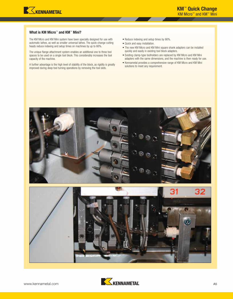
The KM Micro and KM Mini system have been specially designed for use withautomatic lathes, as well as smaller universal lathes. The quick-change cuttingheads reduce indexing and setup times on machines by up to 66%.
The unique flange attachment system enables an additional one to three toolspaces to be used on a single tool block. This considerably increases the toolcapacity of the machine.
A further advantage is the high level of stability of the block, as rigidity is greatlyimproved during deep tool turning operations by removing the tool slots.
• Reduce indexing and setup times by 66%.
• Quick and easy installation.
• The new KM Micro and KM Mini square shank adapters can be installedquickly and easily in existing tool block adapters.
• Existing clamp-type toolholders are replaced by KM Micro and KM Miniadapters with the same dimensions, and the machine is then ready for use.
• Kennametal provides a comprehensive range of KM Micro and KM Minisolutions to meet any requirement.
What is KM Micro™ and KM™ Mini?
KEN_TOOLINGSYSTEMS11_A004_A005.qxp:WIDIA 9:22 AM Page A5
KM Mechanism
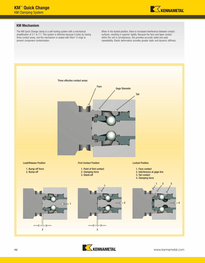
The KM Quick Change clamp is a self-locking system with a mechanical amplification of 3:1 to 7:1. This system is effective because it locks by having three contact areas, and the mechanism is sealed with Viton® O-rings to prevent component contamination.
When in the locked position, there is increased interference between contact surfaces, resulting in superior rigidity. Because the face and taper contact within the unit is simultaneous, this provides accurate radial and axial repeatability. Elastic deformation provides greater static and dynamic stiffness.
A6 www.kennametal.com
KM™ Quick ChangeKM Clamping System
Load/Release Position First Contact Position Locked Position
1. Bump-off force2. Bump-off
1. Point of first contact2. Clamping force3. Stand-off
1. Face contact2. Interference at gage line3. Tail contact4. Clamping force
Face
Three effective contact areas:
Gage Diameter
Tail
1
2 3
2
1
4
1 2 3
KEN_TOOLINGSYSTEMS11_A006_A007.qxp:WIDIA 9:22 AM Page A6

KM Today
All KM Quick Change tooling is made from H13 high-strength steel and comes in a silver satin finish. After the parts are heat treated, qualified pads are machinedinto the part, which increases the repeatability of the clamping mechanism. KM is an ISO standard (26622).
The addition of the ATC configuration and data carrier capability provides machine tool builders with one standard KM design. Integrating these components also enables customers to use data carriers to record tool offsets and tool life information on the tool.
A7www.kennametal.com
KM-TS Standardized System
1. Addition of ATC configuration and data carrier capability:
a. Provides machine tool builders with one standard KM design.
b. Enables customers to use data carriers to record tool offsets and tool life information on the tool.
2. H13 high-strength steel, silver satin finish.
3. Qualification after heat-treat process:
a. Heat-treated, qualified pads are machined into the part, increasing the repeatability.
b. Qualification of the ball tracks after heat treat.
KM63XMZ™ — Designed and used exclusively on Mazak® INTEGREX®
Mark IV Series, i-Series, and J-Series machines.KM80ATC™ — Designed for and used on Giddings & Lewis™ VTLs.
KM Specific Systems
1
®
KM63XMZ
2
3
KM80ATC
®
KM™ Quick ChangeSpecific KM Designs
KEN_TOOLINGSYSTEMS11_A006_A007.qxp:WIDIA 9:22 AM Page A7

A8 www.kennametal.com
KM™ Quick ChangeKM4X™ Features and Benefits
KM4X — The Next Generation Spindle Connection System
• Heavy-duty, rigid configuration with evenly distributed clamping force.• Simple design enables front-loaded spindle configuration.• Balanced-by-design for high spindle speed capacity.• Capable of performing in a wide range of operations from low speed,
high torque to high speed, low torque.
The graph below represents the load capacity of HSK, PSC, and KM4X. The shaded areas represent the typical requirements for heavy duty in various machining processes. KM4X is the only system that can deliver the torque and bending required to achieve high-performance machining.
Some systems may be able to transmit considerable amount of torque, but the cutting forces also generate bending moments that will exceed the interface’s limits before torque limits are exceeded.
KM4X three-surface contact for improved stability and accuracy. Optimized clamping force distribution and interference fit provides
higher stiffness.
torq
ue
bending moment
SK (7/24 Taper)
SK-F (7/24 Taper with Face Contact)
HSKPSC
TS (KM)
KM4XDrilling
Face Milling
Turning
End Milling
Deep Boring
KEN_TOOLINGSYSTEMS11_A008_A009.qxp:WIDIA 2:08 PM Page A8

A9www.kennametal.com
When machining tough materials like titanium, cutting speeds are relatively low due to thermal effects on cutting tools. In response, machine tool builders have improved stiffness and damping on spindles and machine structures over the years. Spindles have been designed with abundant torque at low rotationalspeeds. Nevertheless, the spindle connection remains the weak link in the system.
The spindle connection must provide torque and bending capacity compatible with the machine tool specifications and the requirements for higher productivity. It becomes obvious that in end-milling applications where the projection lengths are typically greater, the limiting factor is bending capacity of the spindle interface.
With more materials that are tougher to machine and require considerably highercutting forces from the machine tool, choosing wisely on the spindle interface tomaximize cutting edge performance is the key to success.
The KM spindle connections greatly outperform the conventional 7/24 steep taper and its face taper contact derivative. HSK and PSC systems with their greater stiffness advantages help minimize undesirable vibrations, gaining the best possible productivity from the machine tool. The KM4X is the best large, heavy-duty spindle connection, where optimal rigidity is necessary. It hassuperb balance between bending and torsion capabilities from the machine tool.
As an example, an indexable helical cutter with 250mm projection from spindle face and 80mm in diameter generates 4620 Nm of bending moment and less than 900 Nm of torque.
Chart shows a comparison of Steep Taper with and without face contact, HSK, and KM4X.
KM™ Quick ChangeKM4X™ Features and Benefits
Choosing What’s Right
F
150mm
deflection
0 600 1200 1800 2400 3000 3600 4200 4800 5400 6000
0.20
0.18
0.16
0.14
0.12
0.10
0.08
0.06
0.04
0.02
0.00
defle
ctio
n (m
) @ 1
50m
m
bending moment (Nm)
7/24 Taper — Size 50
KM4X100
7/24 Taper — Size 50 with Face Contact
HSK125A
7/24 Taper — Size 60
KM4X125
HSK100A
KEN_TOOLINGSYSTEMS11_A008_A009.qxp:WIDIA 2:08 PM Page A9

A10 www.kennametal.com
KM™ Quick ChangeTooling Introduction
Milling and Holemaking
Heat shrinking is not new technology in the tooling industry, but only recently has it been applied to quick-change toolholding systems. Shrink fitting works by having toolholders with an internal bore that is slightly smaller than the connecting end of a cutting shank.
When the toolholder is heated, the bore expands and the shank is able to slip inside the bore. As the toolholder cools, it shrinks, clamping the two pieces together. This creates evenly distributed pressure with minimal vibration between the toolholder and shank that resembles a monoblock tool.
Shrink Fit Technology
How it works...
Advantages of Shrink Fit Tooling:
• Evenly distributed pressure 360° along the length of the cutting tool.
• Slim and short toolholder designs can be achieved due to the lack of moveable parts.
• Absolute symmetry of the grip provides the best possible balance for high-speed operations.
• Stronger clamping force than collet or hydraulic chucks.
• Can be repeated thousands of times.
• Capable of greater speeds and feeds.
• Adapts to various shank types.
• Increased productivity.
®
KEN_TOOLINGSYSTEMS11_A010_A011.qxp:WIDIA 9:22 AM Page A10

A11www.kennametal.com
Kennametal Hydraulic Chucks provide optimum performance when clamping full-cylindrical straight shanks such as solid carbide drills and end mills. Turning a piston pressurizes hydraulic fluid, which expands a thin-walled membrane along the length of the clamping bore.
This creates a secure grip that reduces vibration and eliminates micro-cracking on cutting tools. All chucks are capable of utilizing reducer sleeves to maximize their versatility. Hydraulic chucks require virtually no maintenance, aside fromroutinely cleaning the bore and removing any grease.
Hydraulic Chucks
Slim-shaped hydraulic chucks for universal use with maximum precision.
Slim Line
Prebalanced chucks with an external screw for radial adjustments. This eliminates the need for removing cutting tools to make fine adjustments.
Standard/HP Line
Collet Chucks
An international standard-style collet that can be used in machining applications such as milling, reaming, tapping, and grinding.
ER Collet Series
A single angle collet that grips 1:3 tightening torque versus grip torque without a stop screw.
TG Collet Series
Shell Mill Adapters
All units come standard with a new coolant to the cutting edge capability. This improves tool life and chip control. Shell mill adapters are available in extended lengths and a range of small mounting diameters.
KM™ Quick ChangeTooling Introduction
KEN_TOOLINGSYSTEMS11_A010_A011.qxp:WIDIA 9:22 AM Page A11

A12 www.kennametal.com
KM™ Quick ChangeClamping Introduction
Selection Guide for KM Clamping Systems
There are several things to consider before choosing the correct KM clamping mechanism. Manufacturers should take an account of how much time is spent setting up a machine or changing the tool. Customers should know if they are comfortable with using a torque wrench regularly, as well.
Other issues may arise when considering the machine tool mounting configurations needed to maximize production and cut downtime. KM clamping has options for manufacturers to upgrade their existing machinery and customize it to fit their needs.
KM Manual Quick Change Tooling is the most economical way to reduce costly downtime caused by setup and tool change. With approximately three turns of a readily accessible activation screw, a specified amount of torque is generated, locking the device. KM Manual Clamping Units acceptinternal and external cutting tools, as well as left- and right-handed tools.
The units also enable tools to be inverted if necessary. Variants of machine tool mounting configurations for KM Manual Quick Change Tooling include flange mounts, square, round, and VDI shanks.
KM Manual Clamping Units
KEN_TOOLINGSYSTEMS11_A012_A013.qxp:WIDIA 9:22 AM Page A12
A13www.kennametal.com
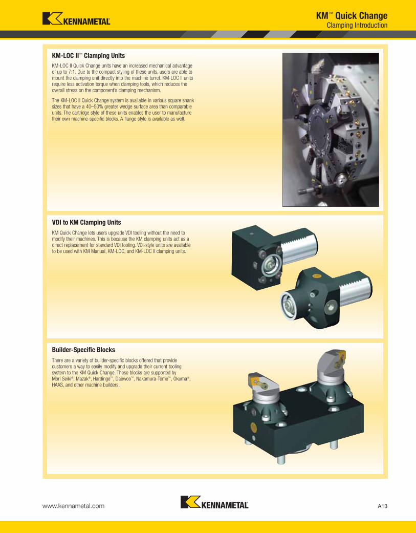
KM-LOC II Quick Change units have an increased mechanical advantage of up to 7:1. Due to the compact styling of these units, users are able to mount the clamping unit directly into the machine turret. KM-LOC II units require less activation torque when clamping tools, which reduces the overall stress on the component’s clamping mechanism.
The KM-LOC II Quick Change system is available in various square shank sizes that have a 40–50% greater wedge surface area than comparable units. The cartridge style of these units enables the user to manufacture their own machine-specific blocks. A flange style is available as well.
KM-LOC II™ Clamping Units
There are a variety of builder-specific blocks offered that provide customers a way to easily modify and upgrade their current tooling system to the KM Quick Change. These blocks are supported by Mori Seiki®, Mazak®, Hardinge™, Daewoo™, Nakamura-Tome™, Okuma®, HAAS, and other machine builders.
Builder-Specific Blocks
KM Quick Change lets users upgrade VDI tooling without the need to modify their machines. This is because the KM clamping units act as a direct replacement for standard VDI tooling. VDI-style units are available to be used with KM Manual, KM-LOC, and KM-LOC II clamping units.
VDI to KM Clamping Units
KM™ Quick ChangeClamping Introduction
KEN_TOOLINGSYSTEMS11_A012_A013.qxp:WIDIA 9:22 AM Page A13
A14 www.kennametal.com
KM™ Quick ChangeClamping Introduction
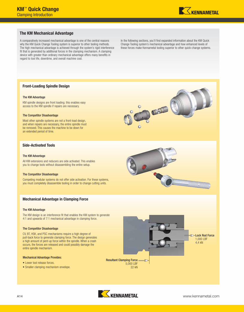
A comparatively increased mechanical advantage is one of the central reasons why the KM Quick Change Tooling system is superior to other tooling methods. The high mechanical advantage is achieved through the system’s rigid interference fit that is generated by additional forces in the clamping mechanism. A clampingdevice with greater than ordinary mechanical advantage offers many benefits inregard to tool life, downtime, and overall machine cost.
In the following sections, you’ll find expanded information about the KM QuickChange Tooling system’s mechanical advantage and how enhanced levels of these forces make Kennametal tooling superior to other quick-change systems.
The KM Mechanical Advantage
The KM Advantage
KM spindle designs are front loading; this enables easy access to the KM spindle if repairs are necessary.
The Competitor Disadvantage
Most other spindle systems are not a front-load design, and when repairs are necessary, the entire spindle must be removed. This causes the machine to be down for an extended period of time.
Front-Loading Spindle Design
The KM Advantage
All KM extensions and reducers are side activated. This enables you to change tools without disassembling the entire setup.
The Competitor Disadvantage
Competing modular systems do not offer side activation. For these systems,you must completely disassemble tooling in order to change cutting units.
Side-Activated Tools
The KM Advantage
The KM design is an interference fit that enables the KM system to generate4:1 and upwards of 7:1 mechanical advantage in clamping force.
The Competitor Disadvantage
CV, BT, HSK, and PSC mechanisms require a high degree of pull-back force to generate clamping force. The design generates a high amount of pent-up force within the spindle. When a crash occurs, the forces are released and could possibly damage the entire spindle mechanism.
Mechanical Advantage in Clamping Force
Resultant Clamping Force5,000 LBF
22 kN
Lock Rod Force1,000 LBF4,4 kN
Mechanical Advantage Provides:
• Lower tool release forces.
• Smaller clamping mechanism envelope.
KEN_TOOLINGSYSTEMS11_A014_A015.qxp:WIDIA 9:23 AM Page A14

A15www.kennametal.com
1. KM Quick Change Tooling
Reduces downtime and increases productivity by cutting the time spent on tool change and setup.
2. Advanced Cutting Tool Materials
Increase production through the utilization of the most advanced cutting tools that enable machines to run longer and faster between tool changes.
3. Tool Kitting
Provides all the tooling (fixturing included) required to complete a production run or shift operation.
4. Pregaged Tooling
Eliminates measuring cuts from the setup process, reduces the risk of human error at the machine control, and provides a quick and efficient method for changing worn tools.
5. Advanced Tool Management Systems
Specifically designed to facilitate the effective management of cutting tools but are equally capable of controlling other types of inventory and consumable goods.
This manufacturing strategy hastens every aspect
of the production process from the machine to the
tool room. It will improve tool maintenance, increase
machining time and productivity, and decrease
non-conforming percentages.
Machine Utilization Strategy (MUS)Tool change and setup/gaging can significantly decrease production
time. Kennametal recommends the implementation of a Machine
Utilization Strategy (MUS). This system incorporates the products,
technologies, and procedures that generate the maximum utility from
capital equipment.
Listed below are the products and services Kennametal recommends to
provide the most time and cost savings, which are principle to the MUS.
KM™ Quick ChangeMachine Utilization Strategy
ISO 26622To learn more, scan here.
For instructions on how to scan,
please see page xxxiii.
KEN_TOOLINGSYSTEMS11_A014_A015.qxp:WIDIA 9:23 AM Page A15

A16 www.kennametal.com
KM™ Quick ChangeProductivity Intro
The power of KennametalKennametal is a world leader in the development, manufacture, application,
and supply of metalcutting tools and services — and the undisputed top
global maker of mining and highway-construction tooling. No matter what
your industry, Kennametal will significantly boost your manufacturing
competitiveness.
Our products are proven to significantly increase machining productivity
and competiveness, as well as generate cost-savings of up to 30% annually.
Our unique Productivity Worksheet can calculate just how much time and
money Kennametal KM™ Quick Change products can save. Enter your data
to see how Kennametal can maximize your competiveness!
Benefits of the Productivity Worksheet:
• See documented savings of 10–30% in machining costs.
• Uses your unique data to compare current productivity
to potential savings.
• Relative and flexible to your specific machines
and operation rates.
• Highlights how lost time can cost your business.
• Tracks weaknesses in machining setup that
can reduce production time.
• Proves the Machine Utilization Strategy (MUS)
is the ultimate way to optimize performance.
The way to increase productivity is simple — complete the Productivity
Worksheet and see how much Kennametal could be saving you. If you’re
impressed by the increase in manufacturing productivity that the calculations
show, contact us. Our application experts are accessible when you need
them and will work with you to solve production problems. Switching to
Kennametal will bring about the manufacturing capability and profits your
business needs to strengthen customer loyalty and thrive in an
increasingly competitive marketplace.
KEN_TOOLINGSYSTEMS11_A016_A017.qxp:WIDIA 9:23 AM Page A16

A17www.kennametal.com
KM Tooling Increase Your Productivity
Step 1 • Enter number of setups on machine per shift:
Step 2 • Enter number of shifts per day:
Step 3 • Enter number of insert changes per shift:
Step 4 • Enter set-up time for conventional tooling (minutes):
Step 5 • Enter insert change time (minutes):
Step 6 • Enter trial cut time (minutes):
Step 7 • Multiply the number of shifts per day (see Step 2)
by number of days per year the machine will be used.
Step 8 • Multiply the number of insert changes per shift (see Step 3)
by the number of shifts per year (see Step 7).
Step 9 • Multiply the number of insert changes per year
(see Step 8) by the % of required trial cuts.
shifts per day
x
days per year
=
shifts per year
conventionaltooling
-
KM Quick ChangeTooling*
=
time savings
(minutes)
- =
- =
insert changes per shift
x
shifts per year
=
insert changesper year
insert changes per year
x
% required trial cuts
=
trial cuts per year
Step 10 • Enter shifts per year from Step 7.
Step 11 • Enter insert changes per year from Step 8.
Step 12 • Enter trial cuts per year from Step 9.
numbertime savings
(minutes)
total
(minutes)
x =
x =
x =
Annual Time Savings with KM Quick Change Tooling Package
total hours saved
x
hourly machine cost
=
annual $$ saved**
=
Issued by:
Machine Manufacturer: Date:
Model and Year:Hourly Cost for Machine:
*Data provided by your Authorized Kennametal Representative. **Annual savings per machine. Multiply by number of machines to see total overall annual savings.
1
2
10
10
3
5
2.5
0.5
0
7.5
2.5
5
2
10
200 400
400
400
4,000
4,000
1,000
1,000
4,000 0.25
5,000
3,000
10,000
7.5
2.5
5
18,000
300 hours
300 $50.00 $15,000.00
18,000 minutes divided by 60 minutes
KM™ Quick ChangeProductivity Worksheet
KEN_TOOLINGSYSTEMS11_A016_A017.qxp:WIDIA 9:23 AM Page A17
A18 www.kennametal.com
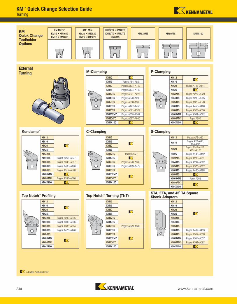
KM™ Quick Change Selection GuideTurning
KM Quick ChangeToolholderOptions
KM Micro™
KM12 • KM1612
KM16 • KM2016
KM™ Mini
KM20 • KM2520
KM25 • KM3225
KM32TS • KM40TS
KM50TS • KM63TS
KM80TS
KM63XMZ KM80ATC KM4X100
External Turning M-Clamping
KM12
KM16 Pages: A84–A85
KM20 Pages: A134–A142
KM25 Pages: A134–A142
KM32TS Pages: A221–A226
KM40TS Pages: A278–A288
KM50TS Pages: A358–A368
KM63TS Pages: A447–A458
KM80TS Pages: A521–A527
KM63XMZ Pages: A558–A561
KM80ATC Pages: A597–A600
KM4X100
P-Clamping
KM12
KM16
KM20 Pages: A143–A144
KM25
KM32TS Pages: A227–A229
KM40TS Pages: A288–A295
KM50TS Pages: A370–A376
KM63TS Pages: A458–A466
KM80TS Pages: A528–A530
KM63XMZ Pages: A561–A562
KM80ATC Page: A600
KM4X100
C-Clamping
KM12
KM16
KM20
KM25
KM32TS Page: A232
KM40TS
KM50TS Pages: A378–A382
KM63TS Pages: A469–A472
KM80TS
KM63XMZ
KM80ATC
KM4X100
Kenclamp™
KM12
KM16
KM20
KM25
KM32TS
KM40TS Pages: A265–A277
KM50TS Pages: A345–A357
KM63TS Pages: A435–A446
KM80TS Pages: A519–A520
KM63XMZ
KM80ATC Pages: A593–A596
KM4X100
S-Clamping
KM12 Pages: A78–A83
KM16Pages: A78–A83,
A94–A97
KM20Pages: A145–A147,
A151–A153KM25 Pages: A145–A152
KM32TS Pages: A230–A231
KM40TS Pages: A297–A302
KM50TS Pages: A376–A377
KM63TS Pages: A466–A468
KM80TS
KM63XMZ Page: A562
KM80ATC
KM4X100
Top Notch™ Turning (TNT)
KM12
KM16
KM20
KM25
KM32TS
KM40TS
KM50TS Pages: A379–A382
KM63TS
KM80TS
KM63XMZ
KM80ATC
KM4X100
Top Notch™ Profiling
KM12
KM16
KM20
KM25
KM32TS Pages: A232–A235
KM40TS Pages: A303–A306
KM50TS Pages: A383–A384
KM63TS Pages: A473–A476
KM80TS
KM63XMZ
KM80ATC
KM4X100
STA, ETA, and 45˚ TA Square Shank Adapters
KM12
KM16
KM20
KM25
KM32TS
KM40TS
KM50TS
KM63TS Pages: A432–A433
KM80TS Pages: A517–A518
KM63XMZ Pages: A554–A557
KM80ATC Pages: A591–A592
KM4X100
Indicates “Not Available”.
KEN_TOOLINGSYSTEMS11_A018_A019.qxp:WIDIA 9:23 AM Page A18
A19www.kennametal.com
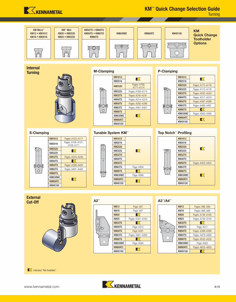
KM™ Quick Change Selection GuideTurning
KM Micro™
KM12 • KM1612
KM16 • KM2016
KM™ Mini
KM20 • KM2520
KM25 • KM3225
KM32TS • KM40TS
KM50TS • KM63TS
KM80TS
KM63XMZ KM80ATC KM4X100
Internal Turning M-Clamping
KM1612
KM2016
KM2520Pages: A168,A171–A174
KM3225 Pages: A166–A174
KM32TS Pages: A240–A241
KM40TS Pages: A314–A316
KM50TS Pages: A392–A396
KM63TS Pages: A481–A487
KM80TS
KM63XMZ
KM80ATC
KM4X100
P-Clamping
KM1612
KM2016
KM2520 Pages: A175–A176
KM3225 Pages: A175–A176
KM32TS Pages: A242–A243
KM40TS Pages: A317–A319
KM50TS Pages: A397–A398
KM63TS Pages: A488–A491
KM80TS
KM63XMZ Pages: A565–A566
KM80ATC
KM4X100
External Cut-Off A2™
KM12 Page: A87
KM16 Page: A87
KM20
KM25 Pages: A161–A162
KM32TS
KM40TS Page: A312
KM50TS Page: A391
KM63TS Pages: A481–A482
KM80TS
KM63XMZ Page: A564
KM80ATC
KM4X100
A3™/A4™
KM12 Pages: A86, A88
KM16 Pages: A86, A88
KM20 Pages: A156–A160
KM25 Pages: A156–A159
KM32TS
KM40TS Page: A311
KM50TS Pages: A389–A390
KM63TS Pages: A479–A480
KM80TS Pages: A532–A535
KM63XMZ Page: A563
KM80ATC Pages: A602–A603
KM4X100
Tunable System KM™
KM1612
KM2016
KM2520
KM3225
KM32TS
KM40TS
KM50TS
KM63TS Page: A494
KM80TS
KM63XMZ Page: A568
KM80ATC
KM4X100
S-Clamping
KM1612 Pages: A103–A111
KM2016Pages: A100–A101,
A109, A111KM2520
KM3225
KM32TS Pages: A244–A246
KM40TS
KM50TS Pages: A399–A402
KM63TS Pages: A491–A492
KM80TS
KM63XMZ
KM80ATC
KM4X100
Top Notch™ Profiling
KM1612
KM2016
KM2520
KM3225
KM32TS
KM40TS
KM50TS Pages: A403–A404
KM63TS
KM80TS
KM63XMZ
KM80ATC
KM4X100
KM Quick ChangeToolholderOptions
Indicates “Not Available”.
KEN_TOOLINGSYSTEMS11_A018_A019.qxp:WIDIA 9:23 AM Page A19

KM Quick ChangeToolholderOptions
KM Micro™
KM12 • KM1612
KM16 • KM2016
KM™ Mini
KM20 • KM2520
KM25 • KM3225
KM32TS • KM40TS
KM50TS • KM63TS
KM80TS
KM63XMZ KM80ATC KM4X100
A20 www.kennametal.com
KM™ Quick Change Selection GuideGrooving
External Grooving Top Notch™ Grooving
KM12 Page: A89
KM16 Pages: A88–A89, A97
KM20 Pages: A153–A154
KM25 Pages: A153–A154
KM32TS Pages: A235–A236
KM40TS Pages: A307–A308
KM50TS Pages: A385–A386
KM63TS Page: A477
KM80TS Page: A531
KM63XMZ
KM80ATC Page: A601
KM4X100
On-Edge Grooving
KM12 Page: A90
KM16 Page: A90
KM20
KM25
KM32TS
KM40TS
KM50TS
KM63TS
KM80TS
KM63XMZ
KM80ATC
KM4X100
Internal Grooving Top Notch™ Grooving
KM1612
KM2016 Page: A102
KM2520 Page: A177
KM3225 Page: A177
KM32TS Page: A247
KM40TS Pages: A320–A322
KM50TS Pages: A406–A407
KM63TS Page: A477
KM80TS Page: A492
KM63XMZ
KM80ATC
KM4X100
A3™/A4™
KM12 Pages: A86, A88
KM16 Pages: A86, A88
KM20 Pages: A156–A160
KM25 Pages: A156–A159
KM32TS
KM40TS Page: A311
KM50TS Pages: A389–A390
KM63TS Pages: A479–A480
KM80TS Pages: A532–A535
KM63XMZ Page: A563
KM80ATC Pages: A602–A603
KM4X100
Kenna Precision™
KM12 Pages: A89–A90
KM16 Pages: A89–A90
KM20
KM25
KM32TS
KM40TS
KM50TS
KM63TS
KM80TS
KM63XMZ
KM80ATC
KM4X100
A3™/A4™
KM1612
KM2016
KM2520 Pages: A180–A182
KM3225 Pages: A180–A182
KM32TS
KM40TS
KM50TS
KM63TS
KM80TS
KM63XMZ
KM80ATC
KM4X100
Indicates “Not Available”.
KEN_TOOLINGSYSTEMS11_A020_A021.qxp:WIDIA 9:23 AM Page A20

KM Micro™
KM12 • KM1612
KM16 • KM2016
KM™ Mini
KM20 • KM2520
KM25 • KM3225
KM32TS • KM40TS
KM50TS • KM63TS
KM80TS
KM63XMZ KM80ATC KM4X100KM Quick ChangeToolholderOptions
A21www.kennametal.com
KM™ Quick Change Selection GuideThreading
Internal Threading Top Notch™ Threading
KM1612
KM2016 Page: A102
KM2520 Page: A177
KM3225 Page: A177
KM32TS Page: A247
KM40TS Pages: A320–A322
KM50TS Pages: A406–A407
KM63TS Page: A492
KM80TS
KM63XMZ
KM80ATC
KM4X100
LT Threading
KM1612
KM2016
KM2520 Page: A178
KM3225 Page: A178
KM32TS Page: A248
KM40TS Page: A323
KM50TS Page: A408
KM63TS
KM80TS
KM63XMZ
KM80ATC
KM4X100
External Threading Top Notch™ Threading
KM12 Page: A89
KM16 Pages: A88–A89, A97
KM20 Pages: A153–A154
KM25 Pages: A153–A154
KM32TS Pages: A235–A236
KM40TS Pages: A307–A308
KM50TS Pages: A385–A386
KM63TS Page: A477
KM80TS Page: A531
KM63XMZ
KM80ATC Page: A601
KM4X100
LT Threading
KM12 Page: A91
KM16 Pages: A91, A97
KM20 Page: A155
KM25 Page: A155
KM32TS Pages: A237–A238
KM40TS Pages: A309–A310
KM50TS Pages: A386–A388
KM63TS Page: A478
KM80TS
KM63XMZ
KM80ATC
KM4X100
On-Edge Threading
KM12 Page: A90
KM16 Page: A90
KM20
KM25
KM32TS
KM40TS
KM50TS
KM63TS
KM80TS
KM63XMZ
KM80ATC
KM4X100
Indicates “Not Available”.
KEN_TOOLINGSYSTEMS11_A020_A021.qxp:WIDIA 9:23 AM Page A21

KM Quick ChangeToolholderOptions
KM Micro™
KM12 • KM1612
KM16 • KM2016
KM™ Mini
KM20 • KM2520
KM25 • KM3225
KM32TS • KM40TS
KM50TS • KM63TS
KM80TS
KM63XMZ KM80ATC KM4X100
A22 www.kennametal.com
KM™ Quick Change Selection GuideMulti-Tasking
External Multi-Tasking 4X STA — KM™
KM12
KM16
KM20
KM25
KM32TS
KM40TS
KM50TS
KM63TS Page: A431
KM80TS
KM63XMZ Page: A553
KM80ATC
KM4X100
2X/4X STA — Square Shanks
KM12
KM16
KM20
KM25
KM32TS
KM40TS
KM50TS
KM63TS
KM80TS
KM63XMZ Page: A556
KM80ATC
KM4X100
External Centerline M-Clamping
KM12
KM16
KM20
KM25
KM32TS
KM40TS
KM50TS Pages: A368–A370
KM63TS Pages: A456–A458
KM80TS
KM63XMZ Pages: A559–A561
KM80ATC
KM4X100
KM™ Reducers
KM12
KM16
KM20
KM25
KM32TS
KM40TS
KM50TS
KM63TS Page: A515
KM80TS
KM63XMZ Page: A588
KM80ATC
KM4X100
Turning AdaptersBoring Bar Adapters
KM1612
KM2016
KM2520 Page: A184
KM3225 Page: A184
KM32TS Pages: A249–A251
KM40TS Pages: A324–A325
KM50TS Pages: A409–A410
KM63TS Page: A495
KM80TS Page: A536
KM63XMZ Page: A569
KM80ATC Page: A604
KM4X100
Boring Bar Sleeves
KM1612
KM2016
KM2520
KM3225
KM32TS Page: A251
KM40TS
KM50TS
KM63TS
KM80TS Page: A570
KM63XMZ Page: A570
KM80ATC Page: A570
KM4X100
Indicates “Not Available”.
KEN_TOOLINGSYSTEMS11_A022_A023.qxp:WIDIA 9:23 AM Page A22
KM Micro™
KM12 • KM1612
KM16 • KM2016
KM™ Mini
KM20 • KM2520
KM25 • KM3225
KM32TS • KM40TS
KM50TS • KM63TS
KM80TS
KM63XMZ KM80ATC KM4X100KM Quick ChangeToolholderOptions
A23www.kennametal.com
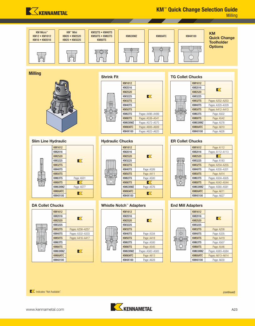
KM™ Quick Change Selection GuideMilling
MillingShrink Fit
KM1612
KM2016
KM2520
KM3225
KM32TS
KM40TS
KM50TS
KM63TS Pages: A496–A499
KM80TS Pages: A538–A541
KM63XMZ Pages: A572–A575
KM80ATC Pages: A606–A609
KM4X100 Pages: A622–A625
TG Collet Chucks
KM1612
KM2016
KM2520
KM3225
KM32TS Pages: A252–A253
KM40TS Pages: A320–A329
KM50TS Pages: A412–A413
KM63TS Page: A502
KM80TS Page: A542
KM63XMZ Page: A578
KM80ATC Page: A610
KM4X100 Page: A626
Hydraulic Chucks
KM1612
KM2016
KM2520
KM3225
KM32TS
KM40TS Page: A326
KM50TS Page: A411
KM63TS Page: A500
KM80TS
KM63XMZ Page: A576
KM80ATC
KM4X100
Slim Line Hydraulic
KM1612
KM2016
KM2520
KM3225
KM32TS
KM40TS
KM50TS
KM63TS Page: A501
KM80TS
KM63XMZ Page: A577
KM80ATC
KM4X100
ER Collet Chucks
KM1612 Page: A112
KM2016 Pages: A112–A113
KM2520
KM3225 Page: A183
KM32TS Pages: A254–A255
KM40TS Pages: A330–A331
KM50TS Page: A414
KM63TS Pages: A504–A505
KM80TS Pages: A542–A544
KM63XMZ Pages: A580–A581
KM80ATC Page: A611
KM4X100 Page: A627
Whistle Notch™ Adapters
KM1612
KM2016
KM2520
KM3225
KM32TS
KM40TS Page: A334
KM50TS Page: A418
KM63TS Page: A500
KM80TS Page: A545
KM63XMZ Pages: A582–A583
KM80ATC Page: A613
KM4X100 Page: A628
DA Collet Chucks
KM1612
KM2016
KM2520
KM3225
KM32TS Pages: A256–A257
KM40TS Pages: A332–A333
KM50TS Pages: A416–A417
KM63TS
KM80TS
KM63XMZ
KM80ATC
KM4X100
End Mill Adapters
KM1612
KM2016
KM2520
KM3225
KM32TS Page: A258
KM40TS Page: A335
KM50TS Page: A419
KM63TS Page: A507
KM80TS Page: A546
KM63XMZ Pages: A583–A584
KM80ATC Pages: A613–A614
KM4X100 Page: A630
Indicates “Not Available”. (continued)
KEN_TOOLINGSYSTEMS11_A022_A023.qxp:WIDIA 9:23 AM Page A23

KM Quick ChangeToolholderOptions
KM Micro™
KM12 • KM1612
KM16 • KM2016
KM™ Mini
KM20 • KM2520
KM25 • KM3225
KM32TS • KM40TS
KM50TS • KM63TS
KM80TS
KM63XMZ KM80ATC KM4X100
Modular Extensions and Reducers KM™ Modular
KM1612
KM2016
KM2520 Page: A185
KM3225 Page: A185
KM32TS Page: A262
KM40TS Page: A342
KM50TS Pages: A427–A428
KM63TS Pages: A314–A315
KM80TS Pages: A549–A550
KM63XMZ Pages: A588–A589
KM80ATC Pages: A617–A618
KM4X100 Page: A634
PSC to KM Modular
PSC63 Page: A619
PSC80 Page: A619
A24 www.kennametal.com
KM™ Quick Change Selection GuideMilling
Milling (continued)Tunable Shell Mill Adapters Shell Mill Adapters
KM1612 Pages: A000–A000
KM2016 Pages:
KM2520 Pages:
KM3225 Pages:
KM32TS Pages:
KM40TS Pages:
KM50TS Pages:
KM63TS Pages:
KM80TS Pages:
KM63XMZ Pages:
KM80ATC Pages:
KM4X100 Pages:
Shell Mill Adapters
KM1612
KM2016
KM2520
KM3225
KM32TS
KM40TS Page: A336
KM50TS Pages: A420–A421
KM63TS Page: A508
KM80TS Page: A547
KM63XMZ Page: A586
KM80ATC Page: A616
KM4X100 Pages: A632–A633
KM1612
KM2016
KM2520
KM3225
KM32TS
KM40TS
KM50TS
KM63TS
KM80TS
KM63XMZ
KM80ATC
KM4X100 Page: A631
Combi-Shell Mill Adapters
KM1612
KM2016
KM2520
KM3225
KM32TS
KM40TS Page: A337
KM50TS Page: A421
KM63TS Page: A509
KM80TS Page: A548
KM63XMZ Page: A587
KM80ATC
KM4X100
Screw-On Adapters
KM1612
KM2016
KM2520
KM3225
KM32TS
KM40TS
KM50TS Page: A422
KM63TS Page: A510
KM80TS Page: A548
KM63XMZ
KM80ATC
KM4X100
Indicates “Not Available”.
KEN_TOOLINGSYSTEMS11_A024_A025.qxp:WIDIA 9:24 AM Page A24

KM Micro™
KM12 • KM1612
KM16 • KM2016
KM™ Mini
KM20 • KM2520
KM25 • KM3225
KM32TS • KM40TS
KM50TS • KM63TS
KM80TS
KM63XMZ KM80ATC KM4X100KM Quick ChangeToolholderOptions
A25www.kennametal.com
KM™ Quick Change Selection GuideAuxiliary
AuxiliaryBlanks Plugs
KM12 Page: A117
KM1612 Page: A117
KM16 Page: A117
KM2016 Page: A117
KM20 Page: A186
KM2520 Page: A186
KM25 Page: A186
KM3225 Page: A186
KM32TS Page: L42
KM40TS Page: L42
KM50TS Page: L42
KM63TS Page: L42
KM80TS Page: L42
KM63XMZ
KM80ATC
KM4X100
KM12 Page: A115
KM1612 Page: A115
KM16 Page: A115
KM2016 Page: A115
KM20 Page: A186
KM2520 Page: A186
KM25 Page: A186
KM3225 Page: A186
KM32TS Page: A263
KM40TS Page: A343
KM50TS Page: A428
KM63TS Page: A515
KM80TS Page: A551
KM63XMZ Page: A589
KM80ATC Page: A618
KM4X100 Page: A635
Gage Bars
KM12 Page: A115
KM16 Page: A115
KM20 Page: A187
KM25 Page: A187
KM32TS Page: A261
KM40TS Page: A343
KM50TS Page: A426
KM63TS Page: A514
KM80TS
KM63XMZ Page: A587
KM80ATC
KM4X100 Page: A635
Timing Heads
KM12 Page: A116
KM16 Page: A116
KM2520
KM3225
KM32TS
KM40TS
KM50TS
KM63TS
KM80TS
KM63XMZ
KM80ATC
KM4X100
Tumble Block
KM12 Page: A117
KM16 Page: A117
KM2520 Page: A189
KM3225 Page: A189
KM32TS
KM40TS
KM50TS
KM63TS
KM80TS
KM63XMZ
KM80ATC
KM4X100
Indicates “Not Available”.
KEN_TOOLINGSYSTEMS11_A024_A025.qxp:WIDIA 9:24 AM Page A25

KM Quick ChangeToolholderOptions
KM Micro™
KM12 • KM1612
KM16 • KM2016
KM™ Mini
KM20 • KM2520
KM25 • KM3225
KM32TS • KM40TS
KM50TS • KM63TS
KM80TS
KM63XMZ KM80ATC KM4X100
A26 www.kennametal.com
KM™ Quick Change Selection GuideAccessories • Drilling
DrillingShrink Fit
KM1612
KM2016
KM2520
KM3225
KM32TS
KM40TS
KM50TS
KM63TS Pages: A496–A499
KM80TS Pages: A538–A541
KM63XMZ Pages: A572–A575
KM80ATC Pages: A606–A609
KM4X100 Pages: A622–A625
Slim Line Hydraulic
KM1612
KM2016
KM2520
KM3225
KM32TS
KM40TS
KM50TS
KM63TS Page: A501
KM80TS
KM63XMZ Page: A577
KM80ATC
KM4X100
TG Collet Chucks
KM1612
KM2016
KM2520
KM3225
KM32TS Pages: A252–A253
KM40TS Pages: A320–A329
KM50TS Pages: A412–A413
KM63TS Page: A502
KM80TS Page: A542
KM63XMZ Page: A578
KM80ATC Page: A610
KM4X100 Page: A626
Hydraulic Chucks
KM1612
KM2016
KM2520
KM3225
KM32TS
KM40TS Page: A326
KM50TS Page: A411
KM63TS Page: A500
KM80TS
KM63XMZ Page: A576
KM80ATC
KM4X100
ER Collet Chucks
KM1612 Page: A112
KM2016 Pages: A112–A113
KM2520
KM3225 Page: A183
KM32TS Pages: A254–A255
KM40TS Pages: A330–A331
KM50TS Page: A414
KM63TS Pages: A504–A505
KM80TS Pages: A542–A544
KM63XMZ Pages: A580–A581
KM80ATC Page: A611
KM4X100 Page: A627
(continued)Indicates “Not Available”.
AccessoriesTorque Wrenches Presetter Shanks
KM12 Page: L52
KM1612 Page: L52
KM16 Page: L52
KM2016 Page: L52
KM20 Page: L52
KM2520 Page: L52
KM25 Page: L52
KM3225 Page: L52
KM32TS Page: L52
KM40TS Page: L52
KM50TS Page: L52
KM63TS Page: L52
KM80TS Page: L52
KM63XMZ Page: L52
KM80ATC Page: L52
KM4X100
KM12 Page: A114
KM1612
KM16 Page: A114
KM2016
KM20 Page: A188
KM2520 Page: A188
KM25 Page: A188
KM3225 Page: A188
KM32TS
KM40TS
KM50TS
KM63TS
KM80TS
KM63XMZ
KM80ATC
KM4X100
KEN_TOOLINGSYSTEMS11_A026_A027.qxp:WIDIA 9:24 AM Page A26

KM Micro™
KM12 • KM1612
KM16 • KM2016
KM™ Mini
KM20 • KM2520
KM25 • KM3225
KM32TS • KM40TS
KM50TS • KM63TS
KM80TS
KM63XMZ KM80ATC KM4X100KM Quick ChangeToolholderOptions
A27www.kennametal.com
KM™ Quick Change Selection GuideDrilling
Drill Chucks
KM1612
KM2016
KM2520
KM3225
KM32TS
KM40TS Page: A333
KM50TS Page: A418
KM63TS
KM80TS
KM63XMZ Page: A582
KM80ATC
KM4X100
DA Collet Chucks
KM1612
KM2016
KM2520
KM3225
KM32TS Pages: A256–A257
KM40TS Pages: A332–A333
KM50TS Pages: A416–A417
KM63TS
KM80TS
KM63XMZ
KM80ATC
KM4X100
Drilling (continued)
Whistle Notch™ Adapters
KM1612
KM2016
KM2520
KM3225
KM32TS
KM40TS Page: A334
KM50TS Page: A418
KM63TS Page: A500
KM80TS Page: A545
KM63XMZ Pages: A582–A583
KM80ATC Page: A613
KM4X100 Page: A628
Straight Shanks
KM1612
KM2016
KM2520
KM3225
KM32TS
KM40TS
KM50TS
KM63TS Page: A511
KM80TS
KM63XMZ Page: A585
KM80ATC Pages: A612–A615
KM4X100 Page: A629
Morse Tapers
KM1612
KM2016
KM2520
KM3225
KM32TS
KM40TS Page: A338
KM50TS Page: A427
KM63TS
KM80TS
KM63XMZ
KM80ATC
KM4X100
Romicron™
KM1612
KM2016
KM2520
KM3225
KM32TS
KM40TS
KM50TS
KM63TS
KM80TS
KM63XMZ Page: A585
KM80ATC
KM4X100
Drill Fix™ Adapters
KM1612
KM2016
KM2520
KM3225
KM32TS
KM40TS
KM50TS
KM63TS Page: A511
KM80TS
KM63XMZ
KM80ATC
KM4X100
(continued)Indicates “Not Available”.
KEN_TOOLINGSYSTEMS11_A026_A027.qxp:WIDIA 9:24 AM Page A27

KM Quick ChangeToolholderOptions
KM Micro™
KM12 • KM1612
KM16 • KM2016
KM™ Mini
KM20 • KM2520
KM25 • KM3225
KM32TS • KM40TS
KM50TS • KM63TS
KM80TS
KM63XMZ KM80ATC KM4X100
A28 www.kennametal.com
KM™ Quick Change Selection GuideDrilling • Tapping
Tapping
TG Collet Chucks
KM1612
KM2016
KM2520
KM3225
KM32TS Pages: A252–A253
KM40TS Pages: A320–A329
KM50TS Pages: A412–A413
KM63TS Page: A502
KM80TS Page: A542
KM63XMZ Page: A578
KM80ATC Page: A610
KM4X100 Page: A626
ER Collet Chucks
KM1612 Page: A112
KM2016 Pages: A112–A113
KM2520
KM3225 Page: A183
KM32TS Pages: A254–A255
KM40TS Pages: A330–A331
KM50TS Page: A414
KM63TS Pages: A504–A505
KM80TS Pages: A542–A544
KM63XMZ Pages: A580–A581
KM80ATC Page: A611
KM4X100 Page: A627
DA Collet Chucks
KM1612
KM2016
KM2520
KM3225
KM32TS Pages: A256–A257
KM40TS Pages: A332–A333
KM50TS Pages: A416–A417
KM63TS
KM80TS
KM63XMZ
KM80ATC
KM4X100
Solid Tapping
KM1612
KM2016
KM2520
KM3225
KM32TS Page: A259
KM40TS Page: A338
KM50TS Page: A423
KM63TS
KM80TS
KM63XMZ
KM80ATC
KM4X100
RC Rapid Change
KM1612
KM2016
KM2520
KM3225
KM32TS
KM40TS
KM50TS
KM63TS Page: A511
KM80TS
KM63XMZ
KM80ATC
KM4X100
Indicates “Not Available”.
Jacobs/DIN
KM1612
KM2016
KM2520
KM3225
KM32TS Pages: A259
KM40TS
KM50TS
KM63TS
KM80TS
KM63XMZ
KM80ATC
KM4X100
Drilling (continued)
KEN_TOOLINGSYSTEMS11_A028_A029.qxp:WIDIA 9:24 AM Page A28

KM Micro™
KM12 • KM1612
KM16 • KM2016
KM™ Mini
KM20 • KM2520
KM25 • KM3225
KM32TS • KM40TS
KM50TS • KM63TS
KM80TS
KM63XMZ KM80ATC KM4X100KM Quick ChangeToolholderOptions
Check the Kennametal website!
Tooling Systems
Visit http://www.kennametal.com/toolingsystems/ to browse our electronic catalog any time you’re looking for Kennametal’s best tooling
solutions. It’s fast, free, and always available. The online e-catalog is updated weekly with products and solutions for milling, turning, holemaking,
and tooling systems applications.
A29
KM™ Quick Change Selection GuideBoring
Indicates “Not Available”.
BoringModBORE™
KM1612
KM2016
KM2520
KM3225
KM32TS Pages: A260–A261
KM40TS Pages: A339–A341
KM50TS Pages: A424–A426
KM63TS Pages: A512–A513
KM80TS
KM63XMZ
KM80ATC
KM4X100
KEN_TOOLINGSYSTEMS11_A028_A029.qxp:WIDIA 9:24 AM Page A29

A30 www.kennametal.com
KM™ offers a variety of
different clamping designs to
suit manufacturing needs. Each unit
design comes in a portfolio of compact
options to further diversify tooling needs
across a multitude of applications. The simple
design of the units utilizes minimal components
to create a strong clamping force with high
mechanical advantage. Having few moving parts,
and requiring a low activation force, means that the
KM Quick Change Clamps operate without a great
deal of maintenance or error.
Conversion and Clamping System Clamping Units
The KM Quick Change modular system offers the
option to build a combination of many possible
cutting tool lengths for best rigidity for the
application, optimizing costs and inventory.
One system for machining centers, mill-turns, and lathes.
Can be integrated directly into the spindle or turret using
standardized clamping unit blocks and/or straight shank
conversions to KM. The KM Quick Change system enables
speedy tool changes for off-machine presetting/insert
changeouts and quicker setup times.
KM™ Quick ChangeConversion and Clamping System
KEN_TOOLINGSYSTEMS11_A030_A031.qxp:WIDIA 9:24 AM Page A30
A31www.kennametal.com
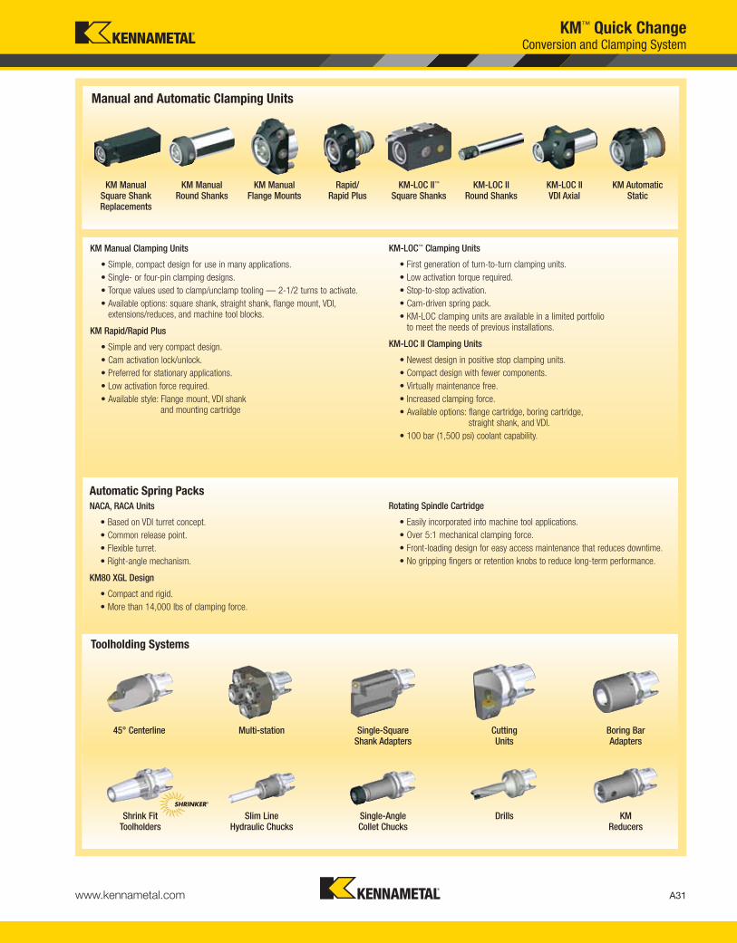
Automatic Spring Packs
NACA, RACA Units
• Based on VDI turret concept.
• Common release point.
• Flexible turret.
• Right-angle mechanism.
KM80 XGL Design
• Compact and rigid.
• More than 14,000 lbs of clamping force.
Rotating Spindle Cartridge
• Easily incorporated into machine tool applications.
• Over 5:1 mechanical clamping force.
• Front-loading design for easy access maintenance that reduces downtime.
• No gripping fingers or retention knobs to reduce long-term performance.
KM Manual Square ShankReplacements
KM ManualRound Shanks
KM ManualFlange Mounts
KM-LOC II™
Square ShanksKM-LOC II
Round ShanksKM-LOC IIVDI Axial
KM AutomaticStatic
Rapid/Rapid Plus
45° Centerline Multi-station Single-SquareShank Adapters
Cutting Units
Boring BarAdapters
Shrink FitToolholders
Slim LineHydraulic Chucks
Single-AngleCollet Chucks
Drills KM Reducers
Manual and Automatic Clamping Units
Toolholding Systems
®
KM™ Quick ChangeConversion and Clamping System
KM Manual Clamping Units
• Simple, compact design for use in many applications.
• Single- or four-pin clamping designs.
• Torque values used to clamp/unclamp tooling — 2-1/2 turns to activate.
• Available options: square shank, straight shank, flange mount, VDI, extensions/reduces, and machine tool blocks.
KM Rapid/Rapid Plus
• Simple and very compact design.
• Cam activation lock/unlock.
• Preferred for stationary applications.
• Low activation force required.
• Available style: Flange mount, VDI shank and mounting cartridge
KM-LOC™ Clamping Units
• First generation of turn-to-turn clamping units.
• Low activation torque required.
• Stop-to-stop activation.
• Cam-driven spring pack.
• KM-LOC clamping units are available in a limited portfolio to meet the needs of previous installations.
KM-LOC II Clamping Units
• Newest design in positive stop clamping units.
• Compact design with fewer components.
• Virtually maintenance free.
• Increased clamping force.
• Available options: flange cartridge, boring cartridge, straight shank, and VDI.
• 100 bar (1,500 psi) coolant capability.
KEN_TOOLINGSYSTEMS11_A030_A031.qxp:WIDIA 9:24 AM Page A31

A32 www.kennametal.com
KM offers a variety of different clamping designs to suit manufacturing needs. Eachunit design comes in a portfolio of compact options to further diversify tooling needsacross a multitude of applications.
The simple design of the units utilizes minimal components to create a strongclamping force with high mechanical advantage. Having few moving parts andrequiring a low activation force, means that the KM Quick Change clamps operatewithout a great deal of maintenance or error.
Clamping Units
Manual Clamping Units
• Simple, compact design for use in many applications.
• Single- or four-pin clamping mechanisms.
• Torque values used to clamp/unclamp tooling — 2-1/2 turns to activate.
• Available options: square shank, straight shank, flange mount, VDI, extensions/reducers, and machine tool blocks.
Single-Pin Design
1. Steel Body2. Canister Pin3. Canister4. Torque Screw5. Lockrod6. Locking Balls7. Bump-Off Pin8. Bump-Off Pin Screws
Error-Proofing Capability for KM Manual Clamping Units
KM Manual units must be disassembled in order to be error proofed.After disassembling the unit, you will find two holes within the canister.To error-proof the unit, insert a metric slotted pin* into one of the holes within the canister. Reassemble, and the clamping unit is now error-proofed.
*Metric Slotted Pins:
• KM40TS — 3mm x 6mm long.
• KM50TS — 4mm x 8mm long.
• KM63TS — 5mm x 10mm long.
• KM80TS — 5mm x 10mm long.
• KM63XMZ — 5mm x 10mm long.
• KM80ATC — 5mm x 10mm long.
Four-Pin Design
1. Steel Body2. Canister Pin (4x)3. Canister4. Torque Screw5. Lockrod6. Locking Balls7. Bump-Off Pin8. Bump-Off Pin Screws9. Canister Screw
4
5
68
3
2
1
6
87
54
1
*
92
3
orientation notch
6
6
78
KM™ Quick ChangeConversion and Clamping System
KEN_TOOLINGSYSTEMS11_A032_A033.qxp:WIDIA 9:25 AM Page A32

A33www.kennametal.com
KM-LOC II clamping units offer an increased mechanical advantage of up to7:1. They require less activation torque, which creates less stress on theclamp’s components. The readily adaptable design of the KM-LOC II clampingunit enables the device’s user to manufacture the tool block as they choose.
KM-LOC II™ Clamping Units
• Newest design in turn-to-turn clamping.
• Compact design with fewer components.
• Single- and two-piece designs.
• Virtually maintenance free.
• Increased clamping force.
• Available options: flange cartridge, boring cartridge, straight shank, and VDI.
• 100 bar (1,500 psi) coolant.
Automatic Spring Packs
NACA, RACA Units
• Based on VDI turret concept.
• Common release point.
• Flexible turret.
• Axial and right-angle mechanism.
• Clamping force provided by disk spring package.
Rotating Spindle
• Easily incorporated into machine tool applications.
• Over 5:1 mechanical clamping force.
• Front-loading design for easy access maintenance that reduces downtime.
• No gripping fingers or retention knobs to reduce long-term performance.
1. KM Spindle Cartridge2. Canister3. Clamping Balls4. Lockrod5. Canister Nut
543
2
1
KM80 XGL Static
• Compact and rigid.
• More than 14,000 lbs of clamping force.
• Clamping force provided by disk spring package.
1
1
3
2
KM™ Quick ChangeConversion and Clamping System
1. Error Proofing
2. Coolant Port
3. Locking Wedges
KEN_TOOLINGSYSTEMS11_A032_A033.qxp:WIDIA 9:25 AM Page A33

A34 www.kennametal.com
KMKM
QuickChange
63System
Size
TSFeature
C-Clamping
Top clamping by
clamping finger for
inserts without hole
M-Clamping
Top and hole clamping
for inserts with hole
P-Clamping
Insert clamping by toggle
lever for insert with hole
S-Clamping
Center clamping by screw
for inserts with hole
PInsert Holding
Method
CInsertShape
LToolholder
Style
NInsert
ClearanceAngle
C
S
KM63TSPCLNR1204
How Do Catalog Numbers Work?Each character in our catalog number signifies a specific trait of thatproduct. Use the following key columns and corresponding imagesto easily identify which attributes apply.
BTS
XMZ
ATC
4X D
K
R
T
V
W
C
N
P
40 = 40mm
50 = 50mm
63 = 63mm
80 = 80mm
100 = 100mm
KM™ Quick ChangeExternal Turning Catalog Numbering System
C
M
P
S
CSMS
KEN_TOOLINGSYSTEMS11_A034_A035.qxp:WIDIA 9:25 AM Page A34

A35www.kennametal.com
Metric
IC
C D K R S T V W
By referencing this easy-to-use guide, you can
identify the correct product to meet your needs.
RHand of Tool
12Insert Size
Cutting Edge Length L10
SpecialFeatures
KM63TSPCLNR1204
04Insert
ThicknessGage
Length
30 = 30mm
45 = 45mm
120 = 120mm
03 = .125"
T3 = .156"
04 = .188"
06 = .250"
07 = .312"
Y = Mazak®
INTEGREX®
M = Metric
L
R = Right hand
L = Left hand
N = Neutral
R
N
AdditionalInformation
MX =
Ceramic
inserts
KM™ Quick ChangeExternal Turning Catalog Numbering System
3,97 04 03 03 06
4,76 04 05 04 04 08 08 S3
5,56 05 06 03 05 05 09 09 03
6,00 06
6,35 06 07 04 06 06 11 11 04
7,94 08 09 05 07 07 13 13 05
8,00 08 11
9,52 09 11 06 09 09 16 16 06
9,52
10,00 10
11,11 11 13 07 11 11 19 19 07
12,00 12
12,70 12 15 08 12 12 22 22 08
14,29 14 17 09 14 14 24 24 09
15,88 16 19 10 15 15 27 27 10
16,00 16
17,46 17 21 11 17 17 30 30 11
19,05 19 23 13 19 19 33 33 13
20,00 20
22,22 22 27 15 22 22 38 38 15
25,00 25
25,40 25 31 17 25 25 44 44 17
31,75 32 38 21 31 31 54 54 21
32,00 32
KEN_TOOLINGSYSTEMS11_A034_A035.qxp:WIDIA 9:25 AM Page A35

A36 www.kennametal.com
How Do Catalog Numbers Work?Each character in our catalog number signifies a specific trait of thatproduct. Use the following key columns and corresponding imagesto easily identify which attributes apply.
KMKM
QuickChange
63System
Size
TSFeature
M
P
S
M-Clamping
Top and hole clamping
for inserts with hole
P-Clamping
Insert clamping by
toggle lever for insert
with hole
S-Clamping
Center clamping
by screw for inserts
with hole
MInsert Holding
Method
CInsertShape
GBar Gage
Length
SBarType
32Bar
Diameter
10 = 10mm
12 = 12mm
16 = 16mm
20 = 20mm
25 = 25mm
32 = 32mm
40 = 40mm
50 = 50mm
KM63TSS32GMCLNR1204
l1(C)
TS
XMZ
ATC
4X
C
S
D
K
R
T
V
W
Special
Steel with through coolant
E
40 = 40mm
50 = 50mm
63 = 63mm
80 = 80mm
100 = 100mm
KM™ Quick ChangeInternal Turning Catalog Numbering System
C 50
D 60
E 70
F 80
G 90
H 100
J 110
K 125
L 140
M 150
N 160
P 170
Q 180
R 200
S 250
T 300
U 350
V 400
W 450
Y 500
X
Carbide with through coolant
S
Ø
CSMS
KEN_TOOLINGSYSTEMS11_A036_A037.qxp:WIDIA 9:25 AM Page A36

A37www.kennametal.com
By referencing this easy-to-use guide, you can
identify the correct product to meet your needs.
RHand
of Tool
12Insert Size
Cutting Edge Length L10
SpecialFeatures
04Insert
Thickness
Y = Mazak®
INTEGREX®
M = Metric
R = Right hand
L = Left hand
LToolholder
Style orLead Angle
NInsert
ClearanceAngle
Metric
IC
03 = .125"
T3 = .156"
04 = .188"
06 = .250"
07 = .312"
3,97 04 03 03 06
4,76 04 05 04 04 08 08 S3
5,56 05 06 03 05 05 09 09 03
6,00 06
6,35 06 07 04 06 06 11 11 04
7,94 08 09 05 07 07 13 13 05
8,00 08 11
9,52 09 11 06 09 09 16 16 06
9,52
10,00 10
11,11 11 13 07 11 11 19 19 07
12,00 12
12,70 12 15 08 12 12 22 22 08
14,29 14 17 09 14 14 24 24 09
15,88 16 19 10 15 15 27 27 10
16,00 16
17,46 17 21 11 17 17 30 30 11
19,05 19 23 13 19 19 33 33 13
20,00 20
22,22 22 27 15 22 22 38 38 15
25,00 25
25,40 25 31 17 25 25 44 44 17
31,75 32 38 21 31 31 54 54 21
32,00 32
KM63TSS32GMCLNR1204
B
C
N
P
KM™ Quick ChangeInternal Turning Catalog Numbering System
R
LC D K R S T V W
KEN_TOOLINGSYSTEMS11_A036_A037.qxp:WIDIA 9:25 AM Page A37
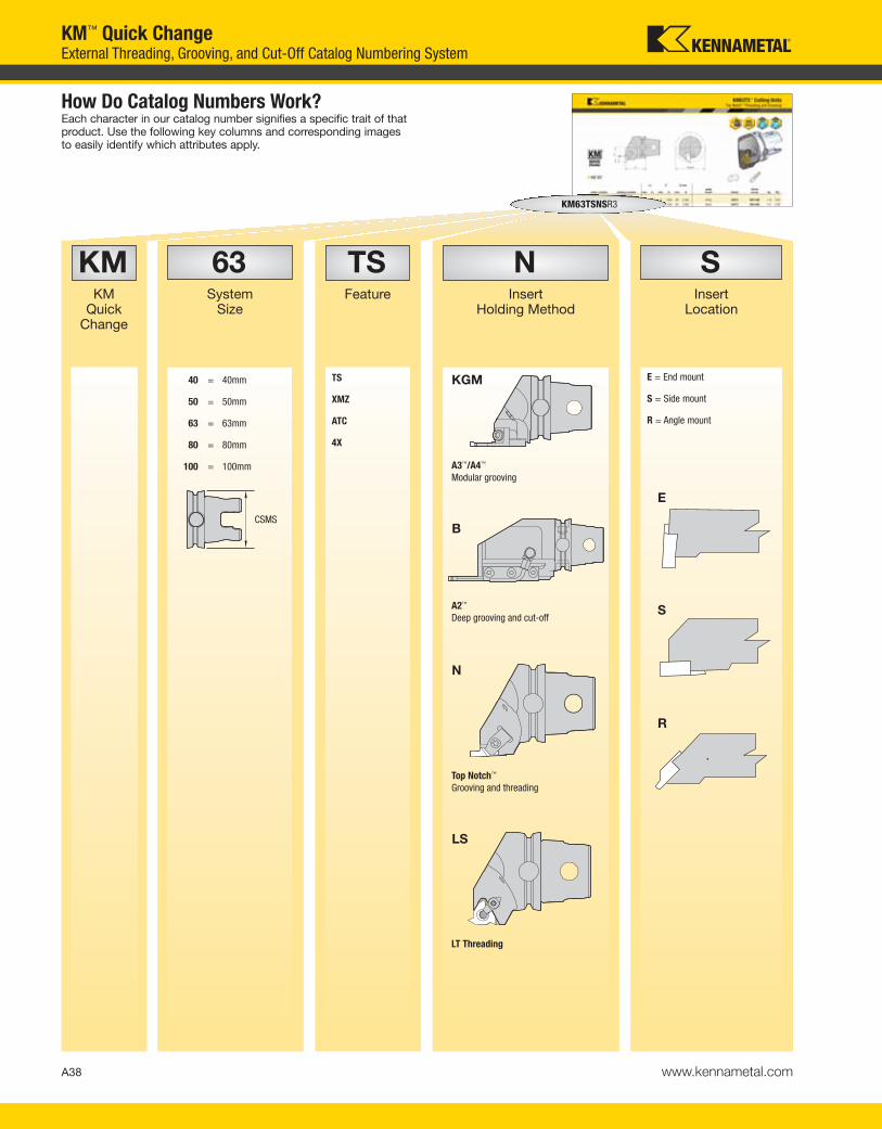
A38 www.kennametal.com
How Do Catalog Numbers Work?Each character in our catalog number signifies a specific trait of thatproduct. Use the following key columns and corresponding imagesto easily identify which attributes apply.
KMKM
Quick Change
63System
Size
TSFeature
NInsert
Holding Method
SInsert
Location
KM63TSNSR3
E
S
R
N
B
LS
KGM E = End mount
S = Side mount
R = Angle mount
TS
XMZ
ATC
4X
A2™
Deep grooving and cut-off
Top Notch™
Grooving and threading
LT Threading
40 = 40mm
50 = 50mm
63 = 63mm
80 = 80mm
100 = 100mm A3™/A4™
Modular grooving
KM™ Quick ChangeExternal Threading, Grooving, and Cut-Off Catalog Numbering System
CSMS
KEN_TOOLINGSYSTEMS11_A038_A039.qxp:WIDIA 9:25 AM Page A38

A39www.kennametal.com
By referencing this easy-to-use guide, you can
identify the correct product to meet your needs.
RHand of Tool
3Insert Size Special
Features
KM63TSNSR3
AdditionalInformation
Y = Mazak®
INTEGREX®
M = Metric
E = External only
N = Internal only
R = Right hand
L = Left hand
R
L
End mount
Side mount
L
R
2 3,18
3 4,95
4 6,48
5 9,65
6 11,13
N = Insert size
S
l = Cutting
edge length I
d
KM™ Quick ChangeExternal Threading, Grooving, and Cut-Off Catalog Numbering System
Top Notch™
KGM
l d (IC)
16 9,52
22 12,70
27 15,88
LT Threading
A2, A3, and A4
1
1B
2
2B
3
4
5
cartridge size
50
65
seat size
KEN_TOOLINGSYSTEMS11_A038_A039.qxp:WIDIA 9:25 AM Page A39
TS
XMZ
ATC
4X
S
Steel with through coolant
E
Carbide with through coolant
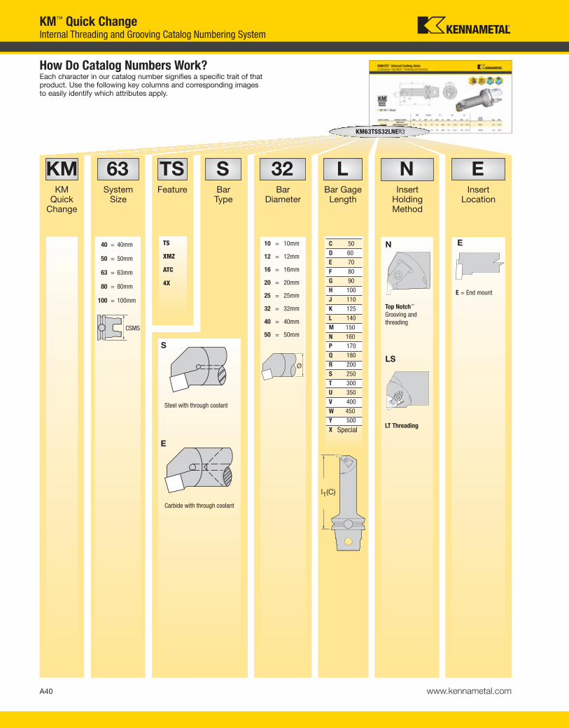
A40 www.kennametal.com
How Do Catalog Numbers Work?Each character in our catalog number signifies a specific trait of thatproduct. Use the following key columns and corresponding imagesto easily identify which attributes apply.
NInsert
HoldingMethod
EInsert
Location
KM63TSS32LNER3
E
E = End mount
N
LS
Top Notch™
Grooving and
threading
LT Threading
KMKM
Quick Change
63System
Size
TSFeature
SBarType
LBar Gage
Length
32Bar
Diameter
10 = 10mm
12 = 12mm
16 = 16mm
20 = 20mm
25 = 25mm
32 = 32mm
40 = 40mm
50 = 50mm
l1(C)
40 = 40mm
50 = 50mm
63 = 63mm
80 = 80mm
100 = 100mm
KM™ Quick ChangeInternal Threading and Grooving Catalog Numbering System
Ø
Special
C 50
D 60
E 70
F 80
G 90
H 100
J 110
K 125
L 140
M 150
N 160
P 170
Q 180
R 200
S 250
T 300
U 350
V 400
W 450
Y 500
X
CSMS
KEN_TOOLINGSYSTEMS11_A040_A041.qxp:WIDIA 9:26 AM Page A40
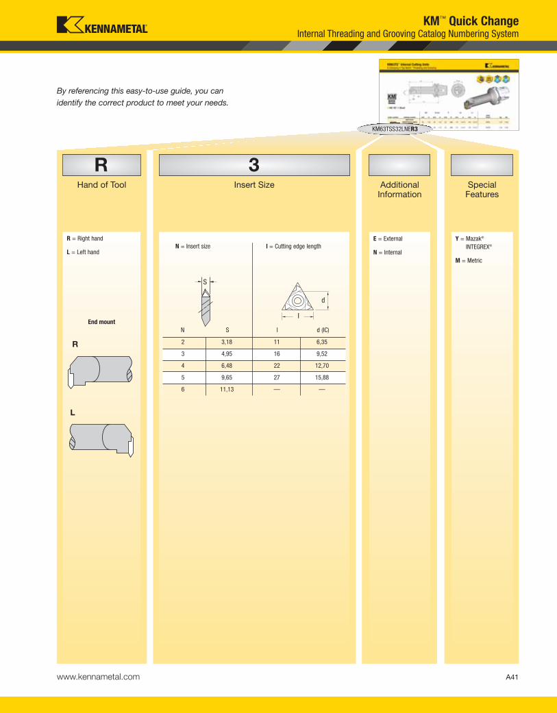
A41www.kennametal.com
By referencing this easy-to-use guide, you can
identify the correct product to meet your needs.
RHand of Tool
3Insert Size Special
Features
KM63TSS32LNER3
AdditionalInformation
Y = Mazak®
INTEGREX®
M = Metric
L
E = External
N = InternalN = Insert size l = Cutting edge length
I
d
S
R = Right hand
L = Left hand
L
End mount
KM™ Quick ChangeInternal Threading and Grooving Catalog Numbering System
2 3,18 11 6,35
3 4,95 16 9,52
4 6,48 22 12,70
5 9,65 27 15,88
6 11,13 — —
l d (IC)N S
R
KEN_TOOLINGSYSTEMS11_A040_A041.qxp:WIDIA 9:26 AM Page A41

A42 www.kennametal.com
KMKM
Quick Change
63System
Size
TSFeature Variance
STAToolholder
Style
How Do Catalog Numbers Work?Each character in our catalog number signifies a specific trait of thatproduct. Use the following key columns and corresponding imagesto easily identify which attributes apply.
LHand
of Tool
L = Left hand
R = Right hand
SpecialFeatures
Y = Mazak®
INTEGREX®
TAR
STA
ETA
KM63TSSTAL
TS
XMZ
ATC
4X
2X
4X
45
TA
40 = 40mm
50 = 50mm
63 = 63mm
80 = 80mm
100 = 100mm
KM™ Quick ChangeTools for Mill-Turn Machines Catalog Numbering System
Side mount
End mount
45º Mount
CSMS
KEN_TOOLINGSYSTEMS11_A042_A043.qxp:WIDIA 9:26 AM Page A42
A43www.kennametal.com
By referencing this easy-to-use guide, you can
identify the correct product to meet your needs.
SpecialFeatures
100Tool Gage
Length
100
Varies according
to toolholder style
100 =
100mm
Y = Mazak®
INTEGREX®
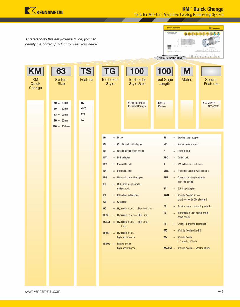
KMKM
Quick Change
63System
Size
TSFeature
TGToolholder
Style
BN = Blank
CS = Combi shell mill adapter
DA = Double-angle collet chuck
DAT = Drill adapter
DFX = Indexable drill
DFT = Indexable drill
EM = Weldon® end mill adapter
ER = DIN 6499 single-angle
collet chuck
ES = KM offset extensions
GB = Gage bar
HC = Hydraulic chuck — Standard Line
HCSL = Hydraulic chuck — Slim Line
HCSLT = Hydraulic chuck — Slim Line
— Trend
HPHC = Hydraulic chuck —
high performance
HPMC = Milling chuck —
high performance
JT = Jacobs taper adapter
MT = Morse taper adapter
P = Spindle plug
RDC = Drill chuck
S = KM extensions-reducers
SMC = Shell mill adapter with coolant
SSF = Adapter for straight shanks
with flat (drills)
ST = Solid tap adapter
SWN = Whistle Notch™ 2° —
short — not to DIN standard
TC = Tension-compression tap adapter
TG = Tremendous Grip single-angle
collet chuck
TT = Shrink Fit thermo toolholder
WD = Whistle Notch with drill
WN = Whistle Notch
(2° metric; 5° inch)
WN/EM = Whistle Notch — Weldon chuck
MMetric
KM63TSTG100100M
TS
XMZ
ATC
4X
40 = 40mm
50 = 50mm
63 = 63mm
80 = 80mm
100 = 100mm
ToolholderStyle Size
KM™ Quick ChangeTools for Mill-Turn Machines Catalog Numbering System
KEN_TOOLINGSYSTEMS11_A042_A043.qxp:WIDIA 9:26 AM Page A43

A44 www.kennametal.com
KMKennametal
Modular
KM12NCMSS
How Do Catalog Numbers Work?Each character in our catalog number signifies a specific trait of that product. Use the following key columns and corresponding images to easily identify which attributes apply.
KM Micro™
and KM™ Mini
Quick Change
Tooling Systems
12System
Size
12 = 12mm
16 = 16mm
20 = 20mm
25 = 25mm
NVersion
N = Neutral
L = Left hand
R = Right hand
E = Offset
CClamping
Unit
MControl
M = Manual
A = Automatic
SSType
E = Carbide round
shank
S = Round shank
SEF = Extended
flange mount
SF = Flange mount
SS = Round shank
with shoulders
KM™ Quick ChangeClamping Units Catalog Numbering Systems
CSMS
KEN_TOOLINGSYSTEMS11_A044_A045.qxp:WIDIA 9:26 AM Page A44

Check the Kennametal website!
Tooling Systems
Visit http://www.kennametal.com/toolingsystems/ to browse our electronic catalog any time you’re looking for Kennametal’s best tooling
solutions. It’s fast, free, and always available. The online e-catalog is updated weekly with products and solutions for milling, turning, holemaking,
and tooling systems applications.
A45
KEN_TOOLINGSYSTEMS11_A044_A045.qxp:WIDIA 9:26 AM Page A45

A46 www.kennametal.com
KM™ Quick ChangeS-Clamping, M-Clamping, and Top Notch™ Profiling Catalog Numbering Systems
KMKennametal
Modular
KM12SCGCR0920HPC
How Do Catalog Numbers Work?Each character in our catalog number signifies a specific trait of that product. Use the following key columns and corresponding images to easily identify which attributes apply.
12System
Size
12 = 12mm
16 = 16mm
20 = 20mm
25 = 25mm
SClampingSystem
S
S-Clamping
Clamped from above with
a screw for indexable
inserts with hole
CInsertShape
GCutting Unit
Shape
M
M-Clamping
Clamped from above and
through hole with using
a pin for indexable
inserts with hole
C
S
D
K
W
E
F
G
H,
J
K
L
M
N
P,
Q
,
R
S
U
V,
XSpecial
Version
A
D
V
CSMS
KM Micro™
and KM™ Mini
Quick Change
Tooling Systems
KEN_TOOLINGSYSTEMS11_A046_A047.qxp:WIDIA 9:26 AM Page A46

A47www.kennametal.com
KM™ Quick ChangeS-Clamping, M-Clamping, and Top Notch™ Profiling Catalog Numbering Systems
20Gage
Length
09Insert Size
RDirection
CClearance
Angle
KM12SCGCR0920HPC
By referencing this easy-to-use guide, you can
identify the correct product to meet your needs.
l
CDV
l
K
l
S
l
T
l
W
B
C
N
P
D
L = Left-hand cutting unit
L1 = Gage length
HPCCoolant
R = Right-hand cutting unit
N = Neutral cutting unit
KEN_TOOLINGSYSTEMS11_A046_A047.qxp:WIDIA 9:26 AM Page A47

A48 www.kennametal.com
04Shank
Diameter
SBoring BarFeatures
1612System Size
KMKennametal
Modular
KM1612S0424SCLDR04S
How Do Catalog Numbers Work?Each character in our catalog number signifies a specific trait of that product. Use the following key columns and corresponding images to easily identify which attributes apply.
24Gage
Length
SClampingSystem
The code is shank
diameter D2.
Ignore digits after
the decimal point.
If the shank
diameter D2 code
is a single digit,
it is preceded by
a 0 (zero). (e.g., for
Ø 8mm = code 08).
1612 = Ø 16mm
2016 = Ø 20mm
2520 = Ø 25mm
3225 = Ø 32mm
S = Tool steel
E = Carbide
The code is gage
length L1.
Ignore digits after
the decimal point. S-Clamping
Clamped from above
with a screw for
indexable inserts
KM™ Quick ChangeS-Clamping Cutting Units Catalog Numbering Systems
S
CSMS
KM Micro™
and KM™ Mini
Quick Change
Tooling Systems
KEN_TOOLINGSYSTEMS11_A048_A049.qxp:WIDIA 9:27 AM Page A48

A49www.kennametal.com
By referencing this easy-to-use guide, you can
identify the correct product to meet your needs.
RDirection
DClearance
Angle
LCutting Unit
Shape
CInsert Shape
KM1612S0424SCLDR04S
04Insert Size
SClampingAccess
L = Left-hand cutting unit R = Right-hand cutting unit
S = Side access
T = Top access
KM™ Quick ChangeS-Clamping Cutting Units Catalog Numbering Systems
C
D
G
45°
T
F
J
K
L
P,
Q
,
U
XSpecial
Version
l
CDGV
l
T
l
W
XSpecial
Version
V
B
C
P
D
KEN_TOOLINGSYSTEMS11_A048_A049.qxp:WIDIA 9:27 AM Page A49
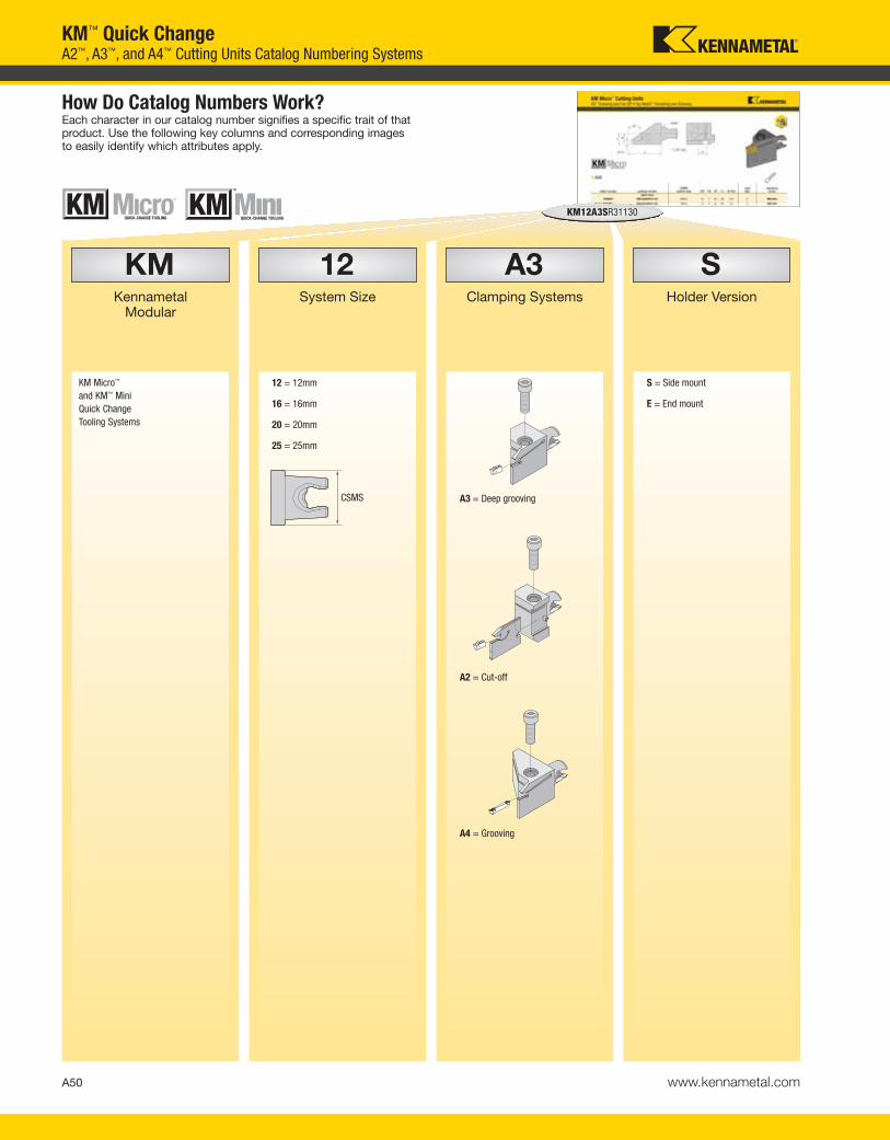
A50 www.kennametal.com
SHolder Version
A3Clamping Systems
12System Size
KMKennametal
Modular
KM12A3SR31130
How Do Catalog Numbers Work?Each character in our catalog number signifies a specific trait of that product. Use the following key columns and corresponding images to easily identify which attributes apply.
12 = 12mm
16 = 16mm
20 = 20mm
25 = 25mm
S = Side mount
E = End mount
A3 = Deep grooving
A4 = Grooving
A2 = Cut-off
KM™ Quick ChangeA2™, A3™, and A4™ Cutting Units Catalog Numbering Systems
CSMS
KM Micro™
and KM™ Mini
Quick Change
Tooling Systems
KEN_TOOLINGSYSTEMS11_A050_A051.qxp:WIDIA 9:27 AM Page A50

A51www.kennametal.com
30Gage Length
11Cutting Depth
3Insert Seat Size
RDirection
KM12A3SR31130
By referencing this easy-to-use guide, you can
identify the correct product to meet your needs.
R = Right hand
07 = 7mm
11 = 11mm
16 = 16mm
L1 = Gage length
L = Left hand
insert
seat size
1
1B
2
2B
3
4
5
KM™ Quick ChangeA2™, A3™, and A4™ Cutting Units Catalog Numbering Systems
KEN_TOOLINGSYSTEMS11_A050_A051.qxp:WIDIA 9:27 AM Page A51
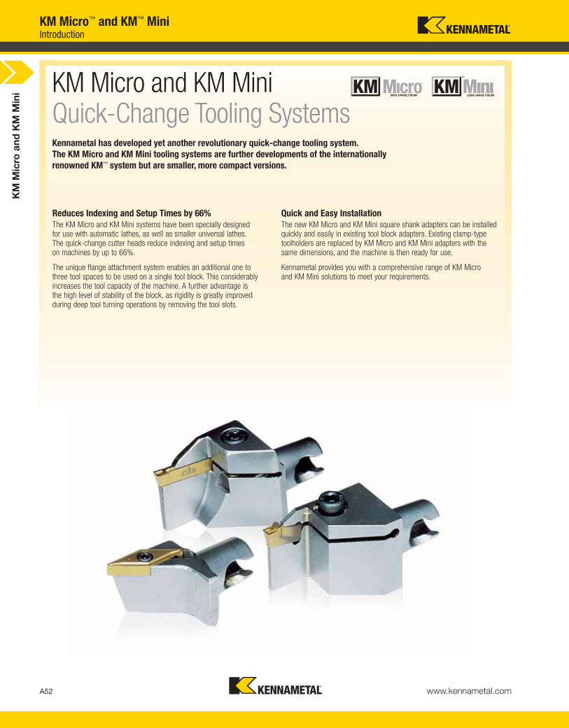
KM
Mic
ro a
nd
KM
Min
i
A52 www.kennametal.com
Kennametal has developed yet another revolutionary quick-change tooling system.
The KM Micro and KM Mini tooling systems are further developments of the internationally
renowned KM™ system but are smaller, more compact versions.
Reduces Indexing and Setup Times by 66%The KM Micro and KM Mini systems have been specially designed for use with automatic lathes, as well as smaller universal lathes. The quick-change cutter heads reduce indexing and setup times on machines by up to 66%.
The unique flange attachment system enables an additional one to three tool spaces to be used on a single tool block. This considerablyincreases the tool capacity of the machine. A further advantage is the high level of stability of the block, as rigidity is greatly improvedduring deep tool turning operations by removing the tool slots.
Quick and Easy InstallationThe new KM Micro and KM Mini square shank adapters can be installedquickly and easily in existing tool block adapters. Existing clamp-typetoolholders are replaced by KM Micro and KM Mini adapters with thesame dimensions, and the machine is then ready for use.
Kennametal provides you with a comprehensive range of KM Micro and KM Mini solutions to meet your requirements.
KM Micro and KM Mini Quick-Change Tooling Systems
KM Micro™ and KM™ MiniIntroduction
KEN_TOOLINGSYSTEMS11_A052_A053.qxp:WIDIA 9:27 AM Page A52
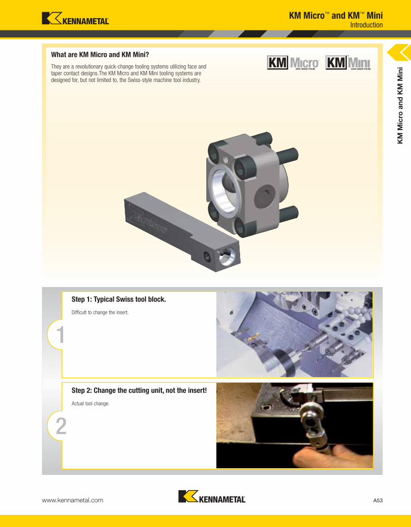
KM
Mic
ro a
nd
KM
Min
i
A53www.kennametal.com
What are KM Micro and KM Mini?
They are a revolutionary quick-change tooling systems utilizing face andtaper contact designs.The KM Micro and KM Mini tooling systems aredesigned for, but not limited to, the Swiss-style machine tool industry.
2
Step 2: Change the cutting unit, not the insert!
Actual tool change.
1
Step 1: Typical Swiss tool block.
Difficult to change the insert.
KM Micro™ and KM™ MiniIntroduction
KEN_TOOLINGSYSTEMS11_A052_A053.qxp:WIDIA 9:27 AM Page A53
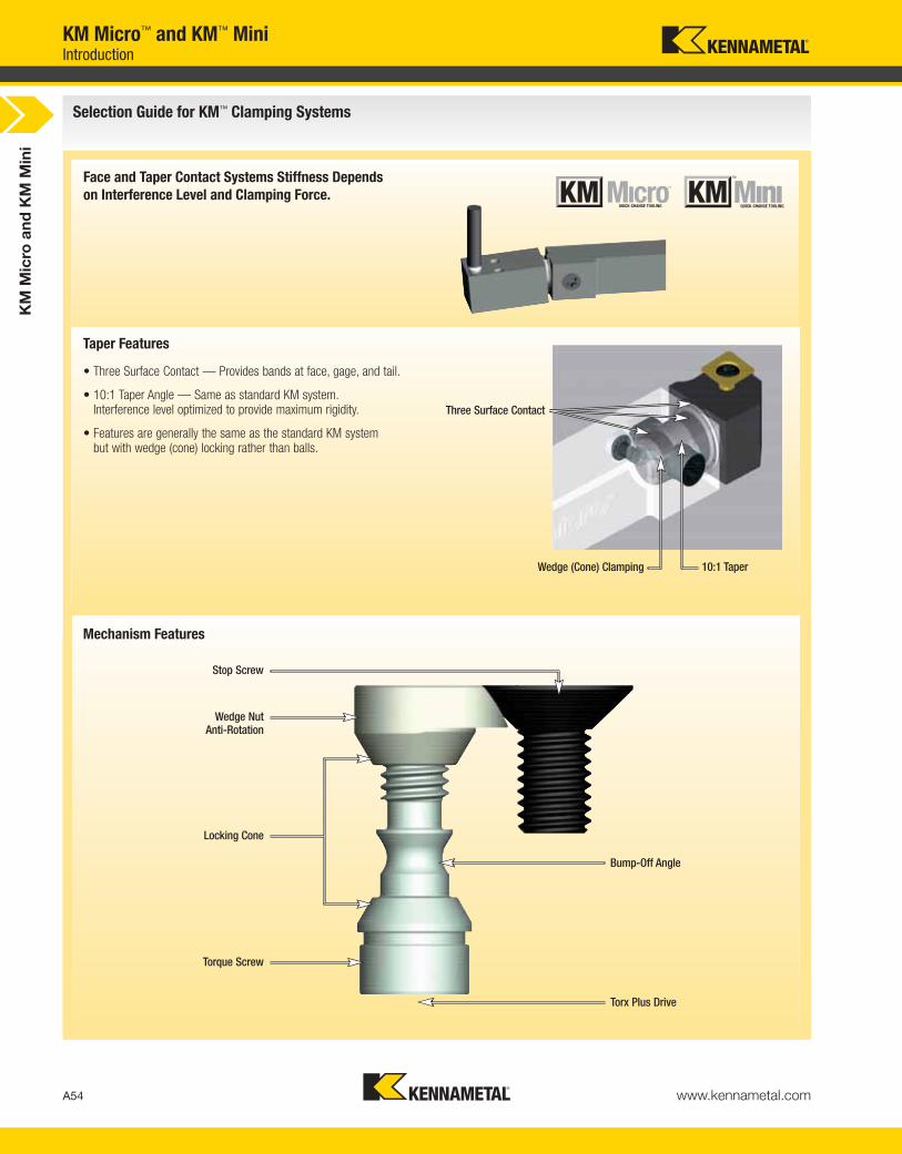
Selection Guide for KM™ Clamping Systems
KM
Mic
ro a
nd
KM
Min
i
A54 www.kennametal.com
Taper Features
Mechanism Features
• Three Surface Contact — Provides bands at face, gage, and tail.
• 10:1 Taper Angle — Same as standard KM system. Interference level optimized to provide maximum rigidity.
• Features are generally the same as the standard KM system but with wedge (cone) locking rather than balls.
Face and Taper Contact Systems Stiffness Depends
on Interference Level and Clamping Force.
Three Surface Contact
Wedge (Cone) Clamping
Wedge NutAnti-Rotation
Locking Cone
Torque Screw
Stop Screw
Bump-Off Angle
Torx Plus Drive
10:1 Taper
KM Micro™ and KM™ MiniIntroduction
KEN_TOOLINGSYSTEMS11_A054_A055.qxp:WIDIA 9:27 AM Page A54

KM
Mic
ro a
nd
KM
Min
i
A55www.kennametal.com
Round Shank Clamping Units
H1
KM Micro™ and KM™ MiniIntroduction
The major difference is center height location of the insert:
What is KM1612™/KM2016™/KM2520™/KM3225™ for I.D. Machining?
The KM1612/KM2016/KM2520/KM3225 is the I.D. end-working tooling product line to complement the KM12™/KM16™/KM20™/KM25™ O.D. turning tooling product line.
• Products are through-coolant capable.
• External tapers are the same as KM12/KM16/KM20/KM25.
KM12/KM16/KM20/KM25Square shank cutting units.Insert is above centerline.
KM1612/KM2016/KM2520/KM3225Centerline cutting units.Insert is on centerline.
KEN_TOOLINGSYSTEMS11_A054_A055.qxp:WIDIA 9:27 AM Page A55

KM
Mic
ro a
nd
KM
Min
i
A56 www.kennametal.com
KM Micro and KM Mini • Features, Functions, and Advantages
• Indexable inserts can be changed outside
the machine:
– Reduces the time required for changing indexable inserts
by up to 60%.
– Reduces the machine setup time by up to 80%.
advantages
KM Micro and KM Mini are a compact
quick-change tooling system.
• The complete cutting unit (including
indexable insert) can be easily changed.
This system does not require special tool adapters or adapter blocks for
installation or replacement operations on your machine.
Square shank adapters for standard
tool blocks.
• Clamping unit sizes in accordance with
industrial standards.
• Fits standard tool adapters.
• Designed for:
– Fixed and sliding
headstock machines.
– Small universal lathes.
• Increased tool capacity
(up to 3 additional tools per tool block).
• Increased rigidity and stability as clamp-type
toolholder slots are not required.
Universal flange clamping units
are a versatile alternative to
square shank adapters.
• Flange attachment systems can also
be retrofitted to existing machines.
As a result, additional tool spaces
can become available.
• The tool block/flange combination can be optimized to meet the
requirements of a machine or a specific workpiece range.
• Very close fitting flange attachment system.
• Optimization of tool length.
Flange attachment units in a wide
range of configurations with or
without coolant facility.
Kennametal offers various flange attachment
units that can be used for a wide range of
turret and tool block configurations and
combinations of modern machines.
• Test cuts are minimized or no longer required.
• Premeasured tools can be installed in the machine:
– Once the deviation/correction value has been specified, the tools
are ready for use.
Face and taper surface contact
between the cutting unit and
clamping units.
• Precise and repeatable cutting edge
position is in both directions of cut.
• Cutting units can be easily changed.
• High clamping forces through low clamping torques.
Simple, but highly effective,
clamping mechanism.
• Secure and release via a screw using
a torque wrench:
– 6,75–8 Nm for KM12™; 3 turns
– 9,5–11 Nm for KM16™; 3 turns
– 19–22 Nm for KM20™
– 34–40 Nm for KM25™
• Large contact surface increases interface life.
• High radial and center height repeatability.
Mating taper clamping surfaces. • Maximum possible surface contact
between the clamping mechanism
and the cutting unit.
• Precise radial positioning.
• The KM design induces positive expansion
of the taper, resulting in secure clamping.
functionsfeatures
KM Micro™ and KM™ MiniIntroduction
Square-shank adapter
Flange attachment system
KEN_TOOLINGSYSTEMS11_A056_A057.qxp:WIDIA 9:28 AM Page A56

Experience the advantages at your Authorized Kennametal Distributor or at www.kennametal.com.
KM Micro™
Quick Change Tooling System
• Quick-change cutter heads reduce indexing and setup times by 66%.
• Specially designed for use with automatic and smaller universal lathes.
• Unique flange attachment system increases machine tool capacity.
• KM Micro square-shank adapters can be installed quickly and easily in existing tool block adapters.
A smaller, more compact version of the internationally renowned KM™ system.
www.kennametal.com
KEN_TOOLINGSYSTEMS11_A056_A057.qxp:WIDIA 9:28 AM Page A57

Features and Benefits
Features• KM Micro is a compact quick-change tooling system.
• Face and taper surface contact between the cutting unit and clamping units.
• Mating taper clamping surfaces.
• Square-shank adapters for standard tool blocks.
Functions• The complete cutting unit (including indexable insert)
can be easily changed.
• Precise and repeatable cutting edge position is in both directions of cut.
• Maximum possible surface contact between the clamping mechanism and the cutting unit.
• Precise radial positioning.
• The KM design induces positive expansion of the taper, resulting in secure clamping.
• Clamping unit sizes in accordance with industrial standards.
• Fits standard tool adapters.
• Designed for:
– Fixed and sliding headstock machines.
– Small universal lathes.
Primary Application• Quick-change cutter heads reduce indexing and setup times by 66%.
• Specially designed for use with automatic and smaller universal lathes.
• Unique flange attachment system increases machine tool capacity.
• KM Micro square-shank adapters can be installed quickly and easily in existing tool block adapters.
KM Micro™ • Quick-Change Tooling System
A58 www.kennametal.com
KEN_TOOLINGSYSTEMS11_A058_A059.qxp:WIDIA 9:28 AM Page A58
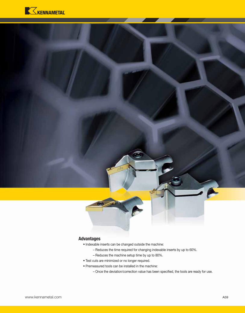
Advantages• Indexable inserts can be changed outside the machine:
– Reduces the time required for changing indexable inserts by up to 60%.
– Reduces the machine setup time by up to 80%.
• Test cuts are minimized or no longer required.
• Premeasured tools can be installed in the machine:
– Once the deviation/correction value has been specified, the tools are ready for use.
A59www.kennametal.com
KEN_TOOLINGSYSTEMS11_A058_A059.qxp:WIDIA 9:28 AM Page A59

CClamping
Unit
NVersion
12System
Size
KMKennametal
Modular
KM12NCM1212100
How Do Catalog Numbers Work?Each character in our catalog number signifies a specific trait of thatproduct. Use the following key columns and corresponding imagesto easily identify which attributes apply.
MControl
A60 www.kennametal.com
KM Micro™ Clamping UnitsClamping Units Catalog Numbering System
KM Micro™ Quick Change
tooling system
12 = Ø 12 x 12mm
16 = Ø 16 x 16mm
N = Neutral
L = Left-hand version
R = Right-hand version
M = Manual
A = Automatic
KEN_TOOLINGSYSTEMS11_A060_A061.qxp:WIDIA 9:28 AM Page A60

A61www.kennametal.com
KM Micro™ Clamping UnitsClamping Units Catalog Numbering System
100Shank Length
12Shank Width
12Shank Height
Type
KM12NCM1212100
14Shoulder Length
19Shank
Diameter
SSType
By referencing this easy-to-use guide, you can
identify the correct product to meet your needs.
27Flange Width
SFType
H = Shank height
B = Shank width
L1 = Shank length
SS = Square shank with shoulders
SF = Flange mount
SEF = Extended flange mount
B2 = Flange width
D = Shank diameter
L2 = Shoulder length
Square shank
B
H
L1
L2
D
B2
KEN_TOOLINGSYSTEMS11_A060_A061.qxp:WIDIA 9:28 AM Page A61

A62 www.kennametal.com
KM Micro™ Clamping UnitsClamping Units Catalog Numbering System
CClamping
Unit
NVersion
12System
Size
KMKennametal
Modular
KM12NCM1212100HPC
How Do Catalog Numbers Work?Each character in our catalog number signifies a specific trait of thatproduct. Use the following key columns and corresponding imagesto easily identify which attributes apply.
MControl
KM Micro™ Quick Change
tooling system
12 = Ø 12 x 12mm
16 = Ø 16 x 16mm
N = Neutral
L = Left-hand version
R = Right-hand version
M = Manual
A = Automatic
KEN_TOOLINGSYSTEMS11_A062_A063.qxp:WIDIA 9:28 AM Page A62

A63www.kennametal.com
KM Micro™ Clamping UnitsClamping Units Catalog Numbering System
100Shank Length
12Shank Width
12Shank Height
Type
KM12NCM1212100HPC
By referencing this easy-to-use guide, you can
identify the correct product to meet your needs.
H = Shank height
B = Shank width
L1 = Shank length
Square shank
B
H
L1
HPCCoolant
KEN_TOOLINGSYSTEMS11_A062_A063.qxp:WIDIA 9:28 AM Page A63

order number catalog numberCSWS
system size B H H1 F L1spare parts
packagewrench size
actuation screw Nm
1922492 KM12NCM1212100 KM12 12,00 11,95 6,00 8,00 100,00 KM12NAPKG 25 IP 7-8
2238505 KM16NCM1616100 KM16 16,00 16,00 8,00 10,00 100,00 KM16NAPKG 27 IP 10-11
KM
Mic
ro C
lam
pin
g U
nit
s
A64 www.kennametal.com
KM Micro™ Clamping UnitsSquare Shanks
� NCM • Metric
� NCM • Inch
order number catalog numberCSWS
system size B H H1 F L1spare parts
packagewrench size
actuation screw ft. lbs.
2238506 KM16NCM10400 KM16 .600 .600 .310 .390 4.000 KM16NAPKG 27 IP 7-8
� R/LCM • Inch
order number catalog numberCSWS
system size B H H1 F L1spare parts
packagewrench size
actuation screw ft. lbs.
right hand
1920380 KM12RCM08400 KM12 .495 .500 .264 .315 4.000 KM12NAPKG 25 IP 5-6
left hand
1925740 KM12LCM08400 KM12 .495 .500 .264 .310 4.000 KM12NAPKG 25 IP 5-6
KEN_TOOLINGSYSTEMS11_A064_A065.qxp:WIDIA 9:28 AM Page A64

KM
Mic
ro C
lam
pin
g U
nit
s
A65www.kennametal.com
order number catalog numberCSWS
system size B H H1 F L1 CSspare parts
packagewrench size
actuation screw ft. lbs.
right hand
3134823 KM16RCM10400HPC KM16 .620 .620 .310 .394 4.000 1/8NPT KM16NAPKG 27 IP 7-8
left hand
3134824 KM16LCM10400HPC KM16 .620 .620 .310 .394 4.000 1/8NPT KM16NAPKG 27 IP 7-8
order number catalog numberCSWS
system size B H H1 F L1 CSspare parts
packagewrench size
actuation screw Nm
right hand
3397255 KM16RCM1616100HPC KM16 16,00 16,00 8,0 10,00 100,00 1/8NPT KM16NAPKG 27 IP 10-11
left hand
3397256 KM16LCM1616100HPC KM16 16,00 16,00 8,0 10,00 100,00 1/8NPT KM16NAPKG 27 IP 10-11
KM Micro™ Clamping Units
� R/LCM-HPC • Metric
� R/LCM-HPC • Inch
� NCM-SF
order number catalog numberCSWS
system size B2 D H2 L L1spare parts
packagewrench size
actuation screw Nm ft. lbs.
1925741 KM12NCMSF1522 KM12 15,75 10 21,5 18 14 KM12NRPKG 25 IP 7-8 5-6
1898043 KM16NCMSF1928 KM16 19,00 14 27,5 22 16 KM16NRPKG 27 IP 10-11 7-8
NOTE: For mounting controls, see page M70.
Square Shanks • Flange Mounts
KEN_TOOLINGSYSTEMS11_A064_A065.qxp:WIDIA 9:28 AM Page A65

D D1 D2 L L1
order number catalog numberCSWS
system size CS mm in mm in mm in mm in mm inspare parts
packagewrench size
actuation screw ft. lbs.
2439982 KM1612NCMSS08055 KM1612 — 12,7 .500 16 .630 20 .787 100 3.937 14 .551 KM12NRPKG 25 IP 5-6
1939520 KM1612NCMSS10055 KM1612 1/8-27 NPT 15,9 .625 16 .630 22 .866 100 3.937 14 .551 KM12NRPKG 25 IP 5-6
1925738 KM1612NCMSS12055 KM1612 1/8-27 NPT 19,1 .750 16 .630 25 .984 100 3.937 14 .551 KM12NRPKG 25 IP 5-6
2440003 KM2016NCMSS08063 KM2016 — 12,7 .500 20 .787 23 .906 100 3.937 16 .630 KM16NRPKG 27 IP 7-8
2440004 KM2016NCMSS10063 KM2016 1/8-27 NPT 15,9 .625 20 .787 25 .984 100 3.937 16 .630 KM16NRPKG 27 IP 7-8
1898048 KM2016NCMSS12063 KM2016 1/8-27 NPT 19,1 .750 20 .787 25 .984 100 3.937 16 .630 KM16NRPKG 27 IP 7-8
1898049 KM2016NCMSS16063 KM2016 1/4-18 NPT 25,4 1.000 20 .787 32 1.260 100 3.937 16 .630 KM16NRPKG 27 IP 7-8
KM
Mic
ro C
lam
pin
g U
nit
s
A66 www.kennametal.com
KM Micro™ Clamping UnitsRound Shanks
� NCM-SS • Metric
order number catalog numberCSWS
system size CS D D1 D2 L L1spare parts
packagewrench size
actuation screw Nm
2439977 KM1612NCMSS1614 KM1612 1/8-27 NPT 16 16 22 100 14 KM12NRPKG 25 IP 7-8
1925739 KM1612NCMSS1914 KM1612 1/8-27 NPT 19 16 25 100 14 KM12NRPKG 25 IP 7-8
2439981 KM1612NCMSS2014 KM1612 1/8-27 NPT 20 16 26 100 14 KM12NRPKG 25 IP 7-8
2439978 KM1612NCMSS2514 KM1612 1/4-18 NPT 25 16 31 100 14 KM12NRPKG 25 IP 7-8
2439979 KM2016NCMSS1616 KM2016 1/8-27 NPT 16 20 25 100 16 KM16NRPKG 27 IP 10-11
1898050 KM2016NCMSS2016 KM2016 1/8-27 NPT 20 20 26 100 16 KM16NRPKG 27 IP 10-11
1898051 KM2016NCMSS2216 KM2016 1/4-18 NPT 22 20 28 100 16 KM16NRPKG 27 IP 10-11
2439980 KM2016NCMSS2516 KM2016 1/4-18 NPT 25 20 31 100 16 KM16NRPKG 27 IP 10-11
� NCM-SS • Inch
KEN_TOOLINGSYSTEMS11_A066_A067.qxp:WIDIA 9:28 AM Page A66

order number catalog numberCSWS
system size D D1 L L2spare parts
packagewrench size
actuation screw ft. lbs.
3016721 KM2016NCME12 KM2016 .75 .79 9.589 .984 KM16NRPKG 27 IP 7-8
order number catalog numberCSWS
system size D D1 L L2spare parts
packagewrench size
actuation screw Nm
3016721 KM2016NCME12 KM2016 19 20 243,56 25,00 KM16NRPKG 27 IP 10-11
KM
Mic
ro C
lam
pin
g U
nit
s
A67www.kennametal.com
order number catalog numberCSWS
system size CS D D1 L L2spare parts
packagewrench size
actuation screw Nm
3016744 KM2016NCMS20 KM2016 1/8 - 27 NPT 20 20 230 20 KM16NRPKG 27 IP 10-11
order number catalog numberCSWS
system size CS D D1 L L2spare parts
packagewrench size
actuation screw ft. lbs.
3016743 KM2016NCMS12 KM2016 1/8 - 27 NPT .75 .79 9.213 .787 KM16NRPKG 27 IP 7-8
KM Micro™ Clamping Units
� NCM-S • Metric
� NCM-S • Inch
� NCM-E • Carbide • Inch
� NCM-E • Carbide • Metric
Round Shanks • Carbide Round Shanks
KEN_TOOLINGSYSTEMS11_A066_A067.qxp:WIDIA 9:29 AM Page A67

KM
Mic
ro C
lam
pin
g U
nit
s
A68 www.kennametal.com
KM Micro™ Clamping UnitsFlange Mounts
� NCMSF
order number catalog numberCSWS
system size B2 D D1 H2 L1 Lspare parts
packagewrench size
actuation screw Nm ft. lbs.
3735627 KM1612NCMSF2127 KM1612 21 17 16 27 14 18 KM12NRPKG 25 IP 7-8 5-6
3735628 KM2016NCMSF2533 KM2016 25 20 20 33 16 22 KM16NRPKG 27 IP 10-11 7-8
NOTE: For mounting controls, see page M71.
KEN_TOOLINGSYSTEMS11_A068_A069.qxp:WIDIA 9:29 AM Page A68

KM4X is designed to take on your most aggressive machining jobs. This next generation KM™ spindle interface should be
your first choice for heavy-duty machining applications. It's especially suited for large structural components, like titanium
aerospace components.
We engineered these rotating and static tool adaptors to handle 3x more bending capacity than similar competitive models.
What does this mean for you?
• Enables full use of machine and cutting tools for the highest productivity.
• Higher metal removal rates.
• Can retrofit to existing machines to boost throughput without buying new equipment.
• Ideal for aerospace and transportation industry machining jobs.
The Next Generation Spindle Interface for Heavy-Duty Machining!
Experience the advantages at your Authorized Kennametal Distributor or at www.kennametal.com.
www.kennametal.com
KM4X™
KEN_TOOLINGSYSTEMS11_A068_A069.qxp:WIDIA 9:29 AM Page A69

A70 www.kennametal.com
KM Micro™ Clamping UnitsS-Clamping, M-Clamping, and Top Notch™ Profiling Cutting Units Catalog Numbering System
KMKennametal
Modular
KM12SCGCR0920
How Do Catalog Numbers Work?Each character in our catalog number signifies a specific trait of thatproduct. Use the following key columns and corresponding imagesto easily identify which attributes apply.
KM Micro™ Quick Change
tooling system
12System
Size
12 = Ø 12 x 12mm
16 = Ø 16 x 16mm
SClampingSystem
S
S-Clamping
Clamped from above with
a screw for indexable
inserts with hole
CInsertShape
GCutting Unit
Shape
M
M-Clamping
Clamped from above and
through hole with using
a pin for indexable
inserts with hole
C
S
D
K
L
D
J
M
A
G
V
W
CSMS
KEN_TOOLINGSYSTEMS11_A070_A071.qxp:WIDIA 9:29 AM Page A70

A71www.kennametal.com
KM Micro™ Clamping UnitsS-Clamping, M-Clamping, and Top Notch™ Profiling Cutting Units Catalog Numbering System
20Gage
Length
09Insert Size
RDirection
CClearance
Angle
KM12SCGCR0920
By referencing this easy-to-use guide, you can
identify the correct product to meet your needs.
l
CDV
l
K
l
S
l
T
l
W
B
C
P
N
L = Left-hand cutting unit
L1 = Gage length
R = Right-hand cutting unit
N = Neutral cutting unit
KEN_TOOLINGSYSTEMS11_A070_A071.qxp:WIDIA 9:29 AM Page A71

KM12A3SR31130
How Do Catalog Numbers Work?Each character in our catalog number signifies a specific trait of thatproduct. Use the following key columns and corresponding imagesto easily identify which attributes apply.
A72 www.kennametal.com
KM Micro™ Clamping UnitsA2™, A3™, and A4™ Cutting Units Catalog Numbering System
SHolder Version
A3Clamping Systems
12System Size
KMKennametal
Modular
12 = 12mm
16 = 16mm
20 = 20mm
25 = 25mm
S = Side mount
E = End mount
A3 = Deep grooving
A2 = Cut-off
CSMS
KM Micro™
and KM™ Mini
Quick Change
tooling systems
A4 = Grooving
KEN_TOOLINGSYSTEMS11_A072_A073.qxp:WIDIA 9:29 AM Page A72

KM12A3SR31130
By referencing this easy-to-use guide, you can
identify the correct product to meet your needs.
A73www.kennametal.com
KM Micro™ Clamping UnitsA2™, A3™, and A4™ Cutting Units Catalog Numbering System
30Gage Length
11Cutting Depth
3Insert Seat Size
RDirection
R = Right hand
07 = 7mm
11 = 11mm
16 = 16mm
L1 = Gage length
L = Left hand
insert
seat size
1
1B
2
2B
3
4
5
KEN_TOOLINGSYSTEMS11_A072_A073.qxp:WIDIA 9:29 AM Page A73
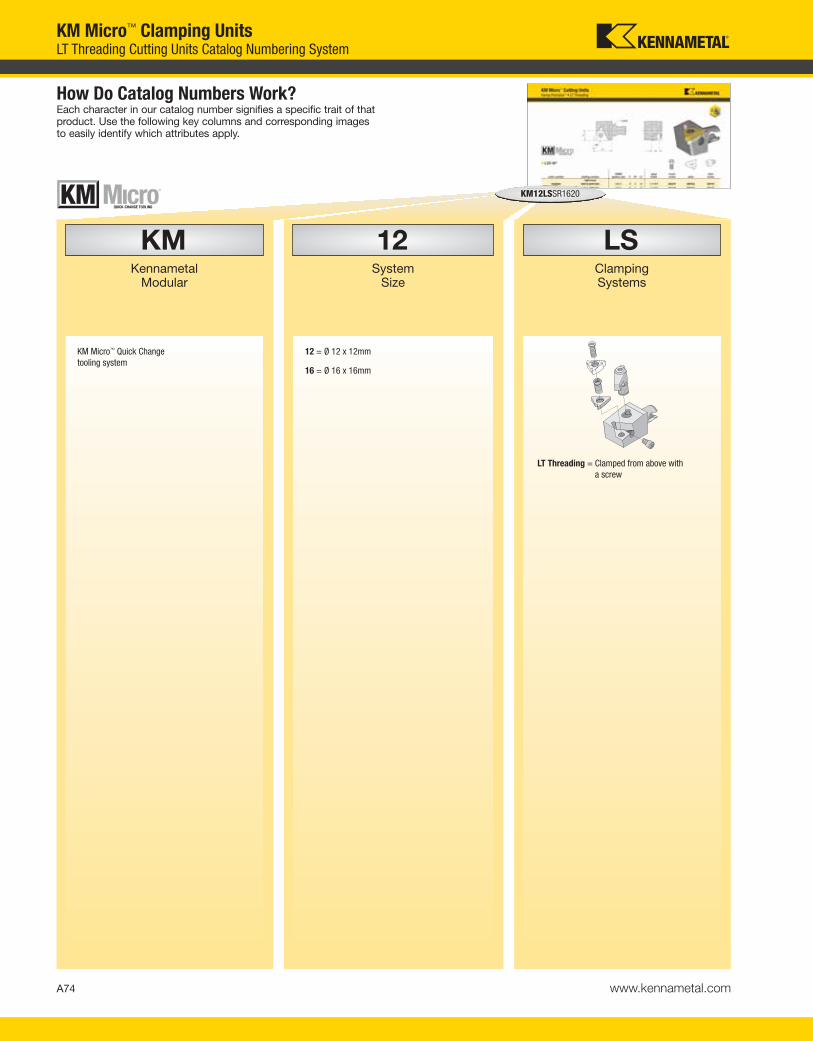
LSClamping Systems
12System
Size
KMKennametal
Modular
KM12LSSR1620
How Do Catalog Numbers Work?Each character in our catalog number signifies a specific trait of thatproduct. Use the following key columns and corresponding imagesto easily identify which attributes apply.
A74 www.kennametal.com
KM Micro™ Clamping UnitsLT Threading Cutting Units Catalog Numbering System
KM Micro™ Quick Change
tooling system
12 = Ø 12 x 12mm
16 = Ø 16 x 16mm
LT Threading = Clamped from above with
a screw
KEN_TOOLINGSYSTEMS11_A074_A075.qxp:WIDIA 9:29 AM Page A74

20Gage
Length
16Insert Size
RDirection
SApplication
KM12LSSR1620
By referencing this easy-to-use guide, you can
identify the correct product to meet your needs.
A75www.kennametal.com
KM Micro™ Clamping UnitsLT Threading Cutting Units Catalog Numbering System
E = End mount
S = Side mount
L1 = Gage length
L = Left-hand cutting unit
R = Right-hand cutting unit
I
d
11 6,35
16 9,52
22 12,70
27 15,88
l d (IC)
l = Cutting edge length
KEN_TOOLINGSYSTEMS11_A074_A075.qxp:WIDIA 9:29 AM Page A75
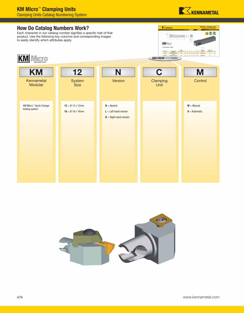
A76 www.kennametal.com
CClamping
Unit
NVersion
12System
Size
KMKennametal
Modular
KM12NCM1212100HPC
MControl
KM Micro™ Quick Change
tooling system
12 = Ø 12 x 12mm
16 = Ø 16 x 16mm
N = Neutral
L = Left-hand version
R = Right-hand version
M = Manual
A = Automatic
KM Micro™ Clamping UnitsClamping Units Catalog Numbering System
How Do Catalog Numbers Work?Each character in our catalog number signifies a specific trait of thatproduct. Use the following key columns and corresponding imagesto easily identify which attributes apply.
KEN_TOOLINGSYSTEMS11_A076_A077.qxp:WIDIA 9:29 AM Page A76

A77www.kennametal.com
KM Micro™ Clamping UnitsClamping Units Catalog Numbering System
100Shank Length
12Shank Width
12Shank Height
Type
KM12NCM1212100HPC
By referencing this easy-to-use guide, you can
identify the correct product to meet your needs.
H = Shank height
B = Shank width
L1 = Shank length
Square shank
B
H
L1
HPCCoolant
KEN_TOOLINGSYSTEMS11_A076_A077.qxp:WIDIA 9:30 AM Page A77

order number catalog numberCSMS
system size F H1 L1gageinsert
insert screw shim
shim screw
right hand
1920382 KM12SCGCR0915 KM12 8 6 15 CC..09T308 MS1155 — —
2226229 KM12SCGCR0920 KM12 8 6 20 CC..09T308 MS1155 — —
1831207 KM16SCGCR0920 KM16 10 8 20 CC..09T308 MS1156 SKCP343 SRS3
left hand
1925742 KM12SCGCL0915 KM12 8 6 15 CC..09T308 MS1155 — —
2226230 KM12SCGCL0920 KM12 8 6 20 CC..09T308 MS1155 — —
1846447 KM16SCGCL0920 KM16 10 8 20 CC..09T308 MS1156 SKCP343 SRS3
KM
Mic
ro C
utt
ing
Un
its
A78 www.kennametal.com
KM Micro™ Cutting UnitsS-Clamping
� SCGC 90°
order number catalog numberCSMS
system size F H1 L1gageinsert
insert screw shim
shim screw
right hand
1920413 KM12SCLCR0915 KM12 8 6 15 CC..09T308 MS1155 — —
2226231 KM12SCLCR0920 KM12 8 6 20 CC..09T308 MS1155 — —
1831206 KM16SCLCR0920 KM16 10 8 20 CC..09T308 MS1156 SKCP343 SRS3
left hand
1925805 KM12SCLCL0915 KM12 8 6 15 CC..09T308 MS1155 — —
2226232 KM12SCLCL0920 KM12 8 6 20 CC..09T308 MS1155 — —
1851750 KM16SCLCL0920 KM16 10 8 20 CC..09T308 MS1156 SKCP343 SRS3
95˚
� SCLC 95°
KEN_TOOLINGSYSTEMS11_A078_A079.qxp:WIDIA 9:30 AM Page A78

KM
Mic
ro C
utt
ing
Un
its
A79www.kennametal.com
order number catalog numberCSMS
system size F H1 L1gageinsert
insert screw shim
shim screw
right hand
1920414 KM12SDACR1120 KM12 8 6 20 DC..11T308 MS1155 — —
1831208 KM16SDACR1120 KM16 10 8 20 DC..11T308 MS1156 SKDP343 SRS3
left hand
1925809 KM12SDACL1120 KM12 8 6 20 DC..11T308 MS1155 — —
1851752 KM16SDACL1120 KM16 10 8 20 DC..11T308 MS1156 SKDP343 SRS3
KM Micro™ Cutting UnitsS-Clamping
� SDAC 90°
order number catalog numberCSMS
system size F H1 L1gageinsert
insert screw shim
shim screw
right hand
1925810 KM12SDJCR1120 KM12 8 6 20 DC..11T308 MS1155 — —
1831209 KM16SDJCR1120 KM16 10 8 20 DC..11T308 MS1156 SKDP343 SRS3
left hand
1925811 KM12SDJCL1120 KM12 8 6 20 DC..11T308 MS1155 — —
1851763 KM16SDJCL1120 KM16 10 8 20 DC..11T308 MS1156 SKDP343 SRS3
� SDJC 93°
KEN_TOOLINGSYSTEMS11_A078_A079.qxp:WIDIA 9:30 AM Page A79

KM
Mic
ro C
utt
ing
Un
its
A80 www.kennametal.com
KM Micro™ Cutting Units
order number catalog numberCSMS
system size F H1 L1gageinsert
insert screw shim
shim screw
2226253 KM12SDPCN1120 KM12 0 6 20 DC..11T308 MS1155 — —
2226254 KM16SDPCN1120 KM16 0 8 20 DC..11T308 MS1156 SKDP343 SRS3
� SDPC 62° 30'
order number catalog numberCSMS
system size F H1 L1gageinsert
insert screw shim
shim screw
right hand
2226255 KM12STGCR1120 KM12 8 6 20 TC..110204 MS1153 — —
1831211 KM16STGCR1120 KM16 10 8 20 TC..110204 MS1153 — —
1831212 KM16STGCR1620 KM16 10 8 20 TC..16T308 MS1156 SKTP343 SRS3
left hand
1925814 KM12STGCL1115 KM12 8 6 15 TC..110204 MS1153 — —
2226256 KM12STGCL1120 KM12 8 6 20 TC..110204 MS1153 — —
1851764 KM16STGCL1120 KM16 10 8 20 TC..110204 MS1153 — —
1851765 KM16STGCL1620 KM16 10 8 20 TC..16T308 MS1156 SKTP343 SRS3
� STGC 90°
S-Clamping
KEN_TOOLINGSYSTEMS11_A080_A081.qxp:WIDIA 9:30 AM Page A80

KM
Mic
ro C
utt
ing
Un
its
A81www.kennametal.com
order number catalog numberCSMS
system size F H1 L1gageinsert
insert screw shim
shim screw
right hand
1925817 KM12STJCR1115 KM12 8 6 15 TC..110204 MS1153 — —
2226257 KM12STJCR1120 KM12 8 6 20 TC..110204 MS1153 — —
1831213 KM16STJCR1120 KM16 10 8 20 TC..110204 MS1153 — —
1831214 KM16STJCR1620 KM16 10 8 20 TC..16T308 MS1156 SKTP343 SRS3
left hand
2226258 KM12STJCL1120 KM12 8 6 20 TC..110204 MS1153 — —
1851766 KM16STJCL1120 KM16 10 8 20 TC..110204 MS1153 — —
1851767 KM16STJCL1620 KM16 10 8 20 TC..16T308 MS1156 SKTP343 SRS3
� STJC 93°
S-ClampingKM Micro™ Cutting Units
KEN_TOOLINGSYSTEMS11_A080_A081.qxp:WIDIA 9:30 AM Page A81
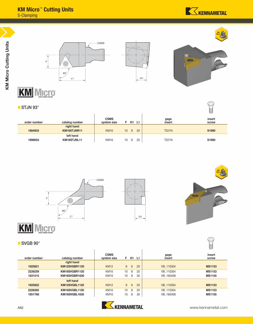
KM
Mic
ro C
utt
ing
Un
its
A82 www.kennametal.com
KM Micro™ Cutting Units
order number catalog numberCSMS
system size F H1 L1gageinsert
insert screw
right hand
1884833 KM16STJNR11 KM16 10 8 20 T221N S1990
left hand
1898054 KM16STJNL11 KM16 10 8 20 T221N S1990
� STJN 93°
order number catalog numberCSMS
system size F H1 L1gageinsert
insert screw
right hand
1925821 KM12SVGBR1120 KM12 8 6 20 VB..110304 MS1153
2226259 KM16SVGBR1120 KM16 10 8 20 VB..110304 MS1153
1831215 KM16SVGBR1630 KM16 10 8 30 VB..160408 MS1155
left hand
1925822 KM12SVGBL1120 KM12 8 6 20 VB..110304 MS1153
2226260 KM16SVGBL1120 KM16 10 8 20 VB..110304 MS1153
1851768 KM16SVGBL1630 KM16 10 8 30 VB..160408 MS1155
� SVGB 90°
S-Clamping
KEN_TOOLINGSYSTEMS11_A082_A083.qxp:WIDIA 9:30 AM Page A82

KM
Mic
ro C
utt
ing
Un
its
A83www.kennametal.com
KM Micro™ Cutting Units
� SVJB 93°
order number catalog numberCSMS
system size F H1 L1gageinsert
insert screw
right hand
1920381 KM12SVJBR1120 KM12 8 6 20 VB..110304 MS1153
1884683 KM16SVJBR1120 KM16 10 8 20 VB..110304 MS1153
1831216 KM16SVJBR1630 KM16 10 8 30 VB..160408 MS1155
left hand
1925823 KM12SVJBL1120 KM12 8 6 20 VB..110304 MS1153
1898056 KM16SVJBL1120 KM16 10 8 20 VB..110304 MS1153
1851770 KM16SVJBL1630 KM16 10 8 30 VB..160408 MS1155
order number catalog numberCSMS
system size F H1 L1gageinsert
insert screw shim
shim screw
right hand
1925824 KM12SWLCR0615 KM12 8 6 15 WC..06T308 MS1155 — —
2226261 KM12SWLCR0620 KM12 8 6 20 WC..06T308 MS1155 — —
1851771 KM16SWLCR0620 KM16 10 8 20 WC..06T308 MS1156 SKWP343 SRS3
left hand
1925825 KM12SWLCL0615 KM12 8 6 15 WC..06T308 MS1155 — —
2226262 KM12SWLCL0620 KM12 8 6 20 WC..06T308 MS1155 — —
1851772 KM16SWLCL0620 KM16 10 8 20 WC..06T308 MS1156 SKWP343 SRS3
� SWLC 95°
S-Clamping
KEN_TOOLINGSYSTEMS11_A082_A083.qxp:WIDIA 9:30 AM Page A83
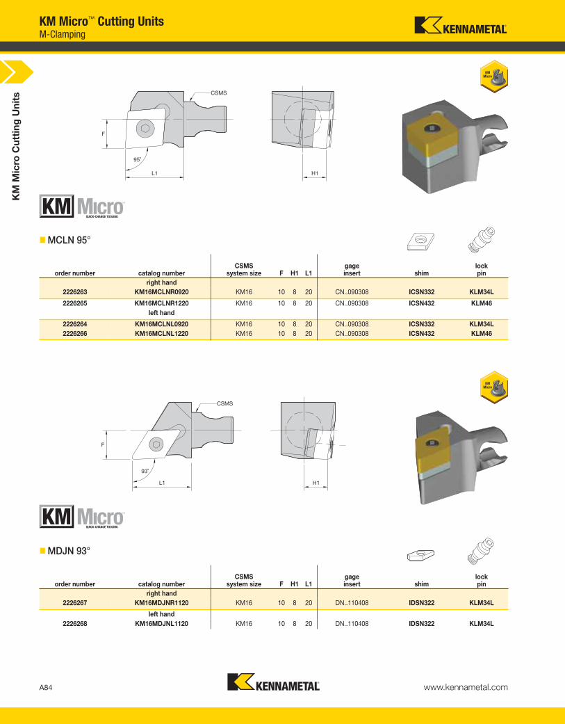
KM
Mic
ro C
utt
ing
Un
its
A84 www.kennametal.com
KM Micro™ Cutting Units
order number catalog numberCSMS
system size F H1 L1gageinsert shim
lock pin
right hand
2226263 KM16MCLNR0920 KM16 10 8 20 CN..090308 ICSN332 KLM34L
2226265 KM16MCLNR1220 KM16 10 8 20 CN..090308 ICSN432 KLM46
left hand
2226264 KM16MCLNL0920 KM16 10 8 20 CN..090308 ICSN332 KLM34L
2226266 KM16MCLNL1220 KM16 10 8 20 CN..090308 ICSN432 KLM46
� MCLN 95°
order number catalog numberCSMS
system size F H1 L1gageinsert shim
lock pin
right hand
2226267 KM16MDJNR1120 KM16 10 8 20 DN..110408 IDSN322 KLM34L
left hand
2226268 KM16MDJNL1120 KM16 10 8 20 DN..110408 IDSN322 KLM34L
� MDJN 93°
M-Clamping
KEN_TOOLINGSYSTEMS11_A084_A085.qxp:WIDIA 9:30 AM Page A84
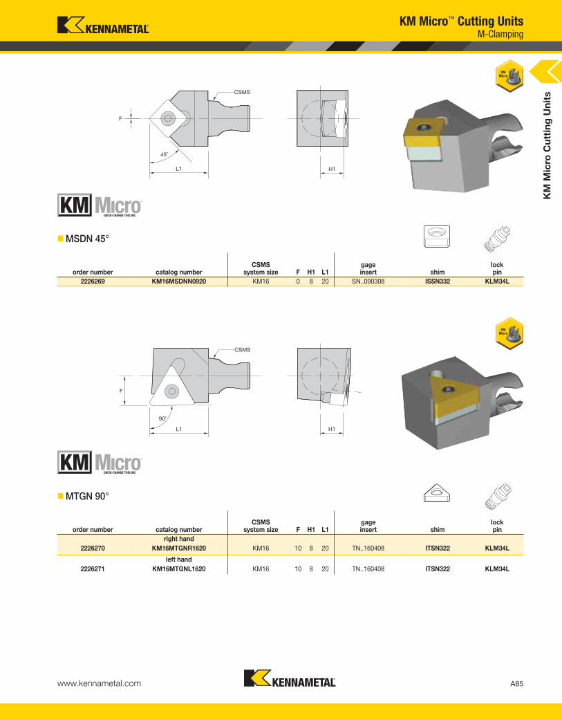
KM
Mic
ro C
utt
ing
Un
its
A85www.kennametal.com
order number catalog numberCSMS
system size F H1 L1gageinsert shim
lock pin
2226269 KM16MSDNN0920 KM16 0 8 20 SN..090308 ISSN332 KLM34L
KM Micro™ Cutting Units
� MSDN 45°
� MTGN 90°
order number catalog numberCSMS
system size F H1 L1gageinsert shim
lock pin
right hand
2226270 KM16MTGNR1620 KM16 10 8 20 TN..160408 ITSN322 KLM34L
left hand
2226271 KM16MTGNL1620 KM16 10 8 20 TN..160408 ITSN322 KLM34L
M-Clamping
KEN_TOOLINGSYSTEMS11_A084_A085.qxp:WIDIA 9:30 AM Page A85

KM
Mic
ro C
utt
ing
Un
its
A86 www.kennametal.com
H1
CD
L1W min
FS
CSMS
KM Micro™ Cutting UnitsA4™ Grooving and Cut-Off
order number catalog numberCSMS
system size CD H1 FS L1 W minseatsize
clampingscrew
clampingscrew
right hand
3377362 KM12A4SCR011330 KM12 13,5 6 7,25 30 1,5 1 MS1156 —
3377360 KM12A4SCR021630 KM12 16,0 6 7,00 30 2,0 2 — MS1944
2226288 KM12A4SCR031630 KM12 16,0 6 6,50 30 3,0 4 — MS1944
3377284 KM16A4SCR011330 KM16 13,5 8 9,25 30 1,5 1 MS1156 —
3377202 KM16A4SCR021630 KM16 16,0 8 9,00 30 2,0 2 — MS1160
2226282 KM16A4SCR031630 KM16 16,0 8 8,44 30 3,0 4 — MS1944
3377200 KM16A4SCR2B1630 KM16 16,0 8 8,75 30 2,5 2B — MS1160
left hand
3377361 KM12A4SCL011330 KM12 13,5 6 7,25 30 1,5 1 MS1156 —
3377359 KM12A4SCL021630 KM12 16,0 6 7,00 30 2,0 2 — MS1944
2226289 KM12A4SCL031630 KM12 16,0 6 6,50 30 3,0 4 — MS1944
3377283 KM16A4SCL011330 KM16 13,5 8 9,25 30 1,5 1 MS1156 —
3377201 KM16A4SCL021630 KM16 16,0 8 9,00 30 2,0 2 — MS1160
2226283 KM16A4SCL031630 KM16 16,0 8 8,44 30 3,0 4 — MS1944
3377199 KM16A4SCL2B1630 KM16 16,0 8 8,75 30 2,5 2B — MS1160
NOTE: W min supplied for reference only. See the Kennametal Innovations Master Catalog Cutting Tools 2013 for actual insert width. Always match seat size of insert to seat size of holder.Seat size 2B cutting units only accept 2B inserts. Seat size 2 cutting units accept size 2 or 2B inserts.
� A4S
KEN_TOOLINGSYSTEMS11_A086_A087.qxp:WIDIA 9:30 AM Page A86

KM
Mic
ro C
utt
ing
Un
its
A87www.kennametal.com
L1 Assy = L1 + L1 BladeF Assy = F + F Blade
KM Micro™ Cutting Units
order number catalog numberCSMS
system size F H1 H2 H3 L1clamping
screw
right hand
1925842 KM12BSR KM12 5,936 6,1 31,3 15,3 4,8 MS1898PKG
1831217 KM16BSR KM16 8,012 8,1 33,0 15,0 4,8 MS1898PKG
left hand
1925843 KM12BSL KM12 5,936 6,1 31,3 15,3 4,8 MS1898PKG
1851793 KM16BSL KM16 8,012 8,1 33,0 15,0 4,8 MS1898PKG
NOTE: For A2 blades, see page A162.
� BS
L1
CD
W
F
� A2BHSN
order number catalog numberseatsize CD W F L1
1984998 A2BHSN19X0116 1 16,0 1,6 1,7 25,2
1851800 A2BHSN19X0211 2 11,0 2,2 2,0 20,2
1851799 A2BHSN19X0216 2 16,0 2,2 2,0 25,2
A2™ Grooving and Cut-Off • A2 Blades
KEN_TOOLINGSYSTEMS11_A086_A087.qxp:WIDIA 9:31 AM Page A87

KM
Mic
ro C
utt
ing
Un
its
A88 www.kennametal.com
KM Micro™ Cutting Units
� A3S
order number catalog numberCSMS
system size CD FS H1 L1 W minseatsize
clampingscrew
right hand
1925837 KM12A3SR31130 KM12 12 7 6,1 30 3,0 3 MS1944
1917367 KM16A3SR31130 KM16 12 9 8,1 30 3,0 3 MS1944
1831218 KM16A3SR41130 KM16 12 8 8,0 30 4,0 4 MS1944
left hand
1925861 KM12A3SL31130 KM12 12 7 6,1 30 3,0 3 MS1944
1925856 KM16A3SL31130 KM16 12 9 8,1 30 3,0 3 MS1944
1851798 KM16A3SL41130 KM16 12 8 8,0 30 4,0 4 MS1944
NOTE: W min supplied for reference only. See the Kennametal Innovations Master Catalog Cutting Tools 2013 for actual insert width. Always match seat size of insert to seat size of holder.
� NE 93°
order number catalog numberCSMS
system size F H1 L1gageinsert clamp
clampingscrew
right hand
1884834 KM16NER220 KM16 10 8 20 NG2L CM147 MS1200
left hand
1898053 KM16NEL220 KM16 10 8 20 NG2R CM146 MS1200
A3™ Grooving and Cut-Off • Top Notch™ Threading and Grooving
KEN_TOOLINGSYSTEMS11_A088_A089.qxp:WIDIA 9:31 AM Page A88

KM
Mic
ro C
utt
ing
Un
its
A89www.kennametal.com
KM Micro™ Cutting Units
� NS 93°
order number catalog numberCSMS
system size F H1 L1gageinsert clamp
clampingscrew
right hand
1920416 KM12NSR220 KM12 8 6 20 NG2R CM146 MS1200
1831203 KM16NSR220 KM16 10 8 20 NG2R CM146 MS1200
1831204 KM16NSR330 KM16 10 8 30 NG3R CM168 MS1220
left hand
1925830 KM12NSL220 KM12 8 6 20 NG2L CM147 MS1200
1846446 KM16NSL220 KM16 10 8 20 NG2L CM147 MS1200
1851748 KM16NSL330 KM16 10 8 30 NG3L CM169 MS1220
� WSJ 2°
order number catalog numberCSMS
system size F H1 L1gageinsert
clampingscrew
right hand
3851787 KM12WSJ15ER20 KM12 8 6 20 KPJ15ER… MS1969PKG
3522575 KM16WSJ15ER20 KM16 10 8 20 KPJ15ER… MS1969PKG
left hand
3851786 KM12WSJ15EL20 KM12 8 6 20 KPJ15EL... MS1969PKG
3522574 KM16WSJ15EL20 KM16 10 8 20 KPJ15EL... MS1969PKG
Top Notch™ Threading and Grooving • Kenna Precision™
KEN_TOOLINGSYSTEMS11_A088_A089.qxp:WIDIA 9:31 AM Page A89

KM
Mic
ro C
utt
ing
Un
its
A90 www.kennametal.com
order number catalog numberCSMS
system size F H1 L1gageinsert
clampingscrew
right hand
3851789 KM12WSK15ER20 KM12 8 6 20 KPK15ER… MS1969PKG
3522577 KM16WSK15ER20 KM16 10 8 20 KPK15ER… MS1969PKG
left hand
3851788 KM12WSK15EL20 KM12 8 6 20 KPK15EL… MS1969PKG
3522576 KM16WSK15EL20 KM16 10 8 20 KPK15EL… MS1969PKG
� WSK 2°
KM Micro™ Cutting UnitsKenna Precision™ • On-Edge Threading and Grooving
order number catalog numberCSMS
system size F H1 L1gageinsert
insert screw
right hand
1925831 KM12STGR1620 KM12 8 6 20 T20G1603R200/T20G32R079 CSTB4SDPKG
1892495 KM16STGR1620 KM16 10 8 20 T20G1603R200/T20G32R079 CSTB4SDPKG
left hand
1925832 KM12STGL1620 KM12 8 6 20 T20G1603L200/T20G32L079 CSTB4SDPKG
1898055 KM16STGL1620 KM16 10 8 20 T20G1603L200/T20G32L079 CSTB4SDPKG
� STG 92°
KEN_TOOLINGSYSTEMS11_A090_A091.qxp:WIDIA 9:31 AM Page A90

KM
Mic
ro C
utt
ing
Un
its
A91www.kennametal.com
order number catalog numberCSMS
system size F H1 L1gageinsert
insert screw shim
shim screw
right hand
2226280 KM12LSSR1620 KM12 8 6 20 LT16ER SSA3T SMYE3 SSY3T
2226290 KM16LSSR1620 KM16 10 8 20 LT16ER SSA3T SMYE3 SSY3T
left hand
2226281 KM12LSSL1620 KM12 8 6 20 LT16EL SSA3T SMYI3 SSY3T
2226291 KM16LSSL1620 KM16 10 8 20 LT16EL SSA3T SMYI3 SSY3T
� LSS 90°
KM Micro™ Cutting UnitsLT Threading
KEN_TOOLINGSYSTEMS11_A090_A091.qxp:WIDIA 9:31 AM Page A91

A92 www.kennametal.com
04Shank
Diameter
SBoring BarFeatures
1612System
Size
KMKennametal
Modular
KM1612S0424SCLDR04S
How Do Catalog Numbers Work?Each character in our catalog number signifies a specific trait of thatproduct. Use the following key columns and corresponding imagesto easily identify which attributes apply.
24Gage
Length
SClampingSystem
KM Micro™
Quick Change
tooling system
The code is shank
diameter D2.
Ignore digits after
the decimal point.
If the shank
diameter D2 code
is a single digit,
it is preceded by
a 0 (zero). (e.g., for
Ø 8mm = code 08).
1612 = Ø 16mm
2016 = Ø 20mm
S = Tool steel
The code is gage
length L1.
Ignore digits after
the decimal point. S-Clamping
Clamped from above
with a screw for
indexable inserts
KM Micro™ Clamping UnitsS-Clamping Cutting Units Catalog Numbering System
S
CSMS
KEN_TOOLINGSYSTEMS11_A092_A093.qxp:WIDIA 9:31 AM Page A92
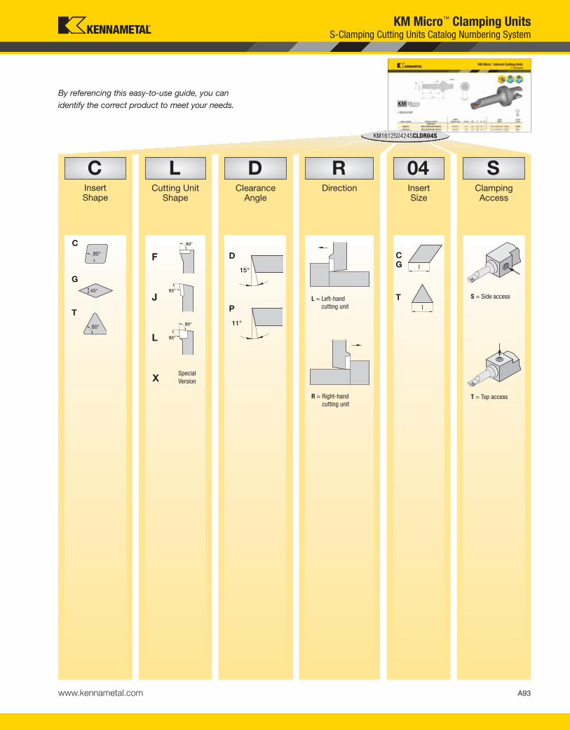
A93www.kennametal.com
By referencing this easy-to-use guide, you can
identify the correct product to meet your needs.
RDirection
DClearance
Angle
LCutting Unit
Shape
CInsert Shape
KM1612S0424SCLDR04S
04Insert Size
SClampingAccess
S = Side access
T = Top access
KM Micro™ Clamping UnitsS-Clamping Cutting Units Catalog Numbering System
C
G
45°
T
F
J
L
XSpecial
Version
l
CG
l
T
D
P
L = Left-hand
cutting unit
R = Right-hand
cutting unit
KEN_TOOLINGSYSTEMS11_A092_A093.qxp:WIDIA 9:31 AM Page A93

order number catalog numberCSMS
system size F H1 L1gageinsert
insert screw
right hand
3180670 KM16SCLCR0920HPC KM16 10 2 20 CC..09T308/CC..3252 MS1155
left hand
3180671 KM16SCLCL0920HPC KM16 10 2 20 CC..09T308/CC..3252 MS1155
KM
Mic
ro C
utt
ing
Un
its
A94 www.kennametal.com
KM Micro™ Cutting Units
� SCLC-HPC 95°
order number catalog numberCSMS
system size F H1 L1gageinsert
insert screw
right hand
3176692 KM16SDJCR1120HPC KM16 10 2 20 DC..11T308/DC..3252 MS1155
left hand
3180663 KM16SDJCL1120HPC KM16 10 2 20 DC..11T308/DC..3252 MS1155
� SDJC-HPC 93°
S-Clamping
KEN_TOOLINGSYSTEMS11_A094_A095.qxp:WIDIA 9:31 AM Page A94
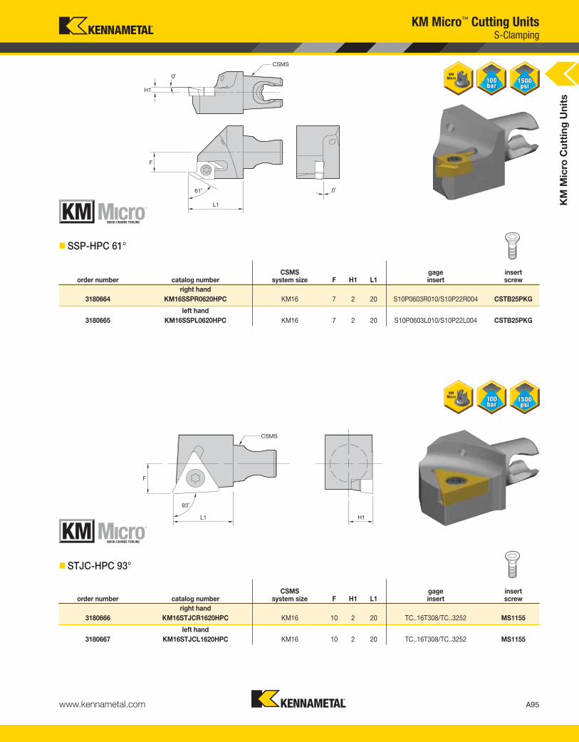
KM
Mic
ro C
utt
ing
Un
its
A95www.kennametal.com
� SSP-HPC 61°
order number catalog numberCSMS
system size F H1 L1gageinsert
insert screw
right hand
3180664 KM16SSPR0620HPC KM16 7 2 20 S10P0603R010/S10P22R004 CSTB25PKG
left hand
3180665 KM16SSPL0620HPC KM16 7 2 20 S10P0603L010/S10P22L004 CSTB25PKG
KM Micro™ Cutting Units
order number catalog numberCSMS
system size F H1 L1gageinsert
insert screw
right hand
3180666 KM16STJCR1620HPC KM16 10 2 20 TC..16T308/TC..3252 MS1155
left hand
3180667 KM16STJCL1620HPC KM16 10 2 20 TC..16T308/TC..3252 MS1155
� STJC-HPC 93°
S-Clamping
KEN_TOOLINGSYSTEMS11_A094_A095.qxp:WIDIA 9:31 AM Page A95
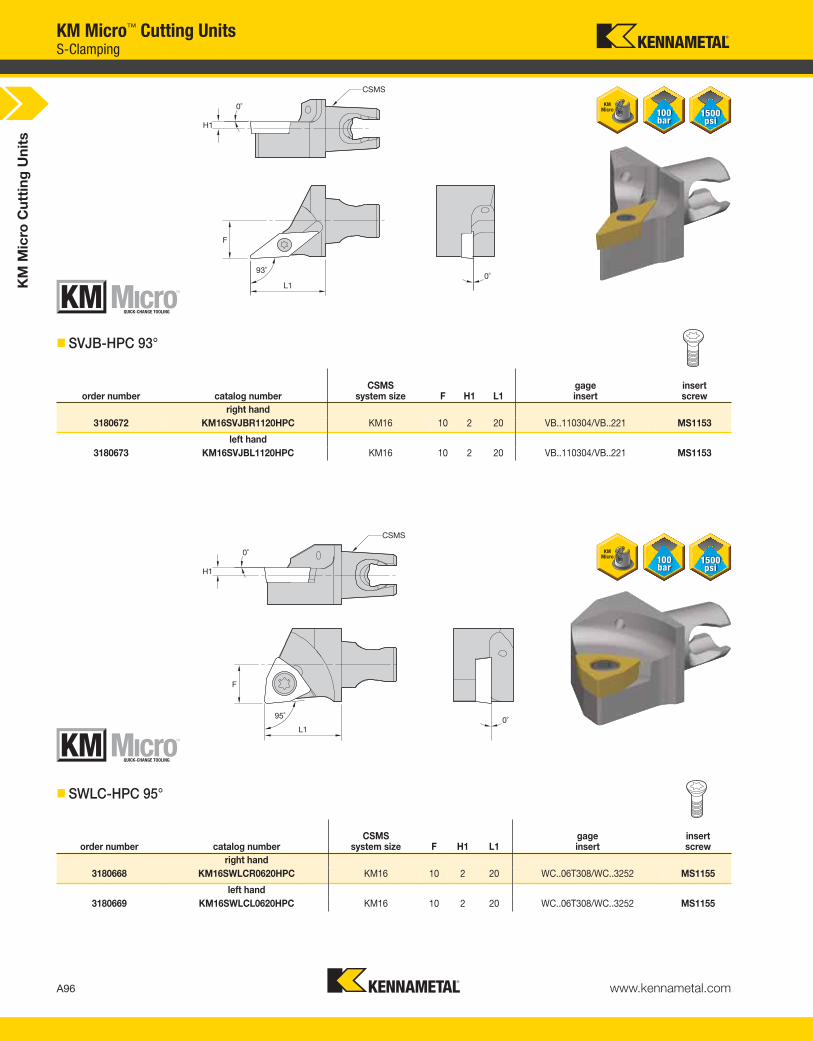
KM
Mic
ro C
utt
ing
Un
its
A96 www.kennametal.com
� SVJB-HPC 93°
order number catalog numberCSMS
system size F H1 L1gageinsert
insert screw
right hand
3180672 KM16SVJBR1120HPC KM16 10 2 20 VB..110304/VB..221 MS1153
left hand
3180673 KM16SVJBL1120HPC KM16 10 2 20 VB..110304/VB..221 MS1153
KM Micro™ Cutting Units
� SWLC-HPC 95°
order number catalog numberCSMS
system size F H1 L1gageinsert
insert screw
right hand
3180668 KM16SWLCR0620HPC KM16 10 2 20 WC..06T308/WC..3252 MS1155
left hand
3180669 KM16SWLCL0620HPC KM16 10 2 20 WC..06T308/WC..3252 MS1155
S-Clamping
KEN_TOOLINGSYSTEMS11_A096_A097.qxp:WIDIA 9:31 AM Page A96

KM
Mic
ro C
utt
ing
Un
its
A97www.kennametal.com
� NS-HPC
order number catalog numberCSMS
system size F H1 L1gageinsert clamp
clampingscrew
right hand
3180674 KM16NSR220HPC KM16 10 2 20 NG2R CM146 MS1200
left hand
3180675 KM16NSL220HPC KM16 10 2 20 NG2L CM147 MS1200
KM Micro™ Cutting Units
� LSS-HPC
order number catalog numberCSMS
system size F H1 L1gageinsert
insert screw shim
shim screw
right hand
3180676 KM16LSSR1620HPC KM16 10 2 20 LT16ER SSA3T SMYE3 SSY3T
left hand
3180677 KM16LSSL1620HPC KM16 10 2 20 LT16EL SSA3T SMYI3 SSY3T
Top Notch™ Threading and Grooving • LT Threading
KEN_TOOLINGSYSTEMS11_A096_A097.qxp:WIDIA 9:31 AM Page A97
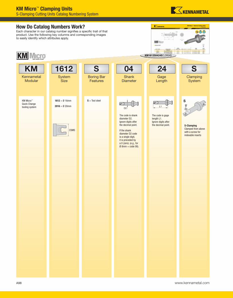
A98 www.kennametal.com
04Shank
Diameter
SBoring BarFeatures
1612System
Size
KMKennametal
Modular
KM1612S0424SCLDR04S
How Do Catalog Numbers Work?Each character in our catalog number signifies a specific trait of thatproduct. Use the following key columns and corresponding imagesto easily identify which attributes apply.
24Gage
Length
SClampingSystem
KM Micro™
Quick Change
tooling system
The code is shank
diameter D2.
Ignore digits after
the decimal point.
If the shank
diameter D2 code
is a single digit,
it is preceded by
a 0 (zero). (e.g., for
Ø 8mm = code 08).
1612 = Ø 16mm
2016 = Ø 20mm
S = Tool steel
The code is gage
length L1.
Ignore digits after
the decimal point. S-Clamping
Clamped from above
with a screw for
indexable inserts
KM Micro™ Clamping UnitsS-Clamping Cutting Units Catalog Numbering System
S
CSMS
KEN_TOOLINGSYSTEMS11_A098_A099.qxp:WIDIA 9:32 AM Page A98

A99www.kennametal.com
By referencing this easy-to-use guide, you can
identify the correct product to meet your needs.
RDirection
DClearance
Angle
LCutting Unit
Shape
CInsert Shape
KM1612S0424SCLDR04S
04Insert Size
SClampingAccess
L = Left-hand cutting unit R = Right-hand cutting unit
S = Side access
T = Top access
KM Micro™ Clamping UnitsS-Clamping Cutting Units Catalog Numbering System
C
G
45°
T
F
J
L
XSpecial
Version
l
CG
l
T
D
P
KEN_TOOLINGSYSTEMS11_A098_A099.qxp:WIDIA 9:32 AM Page A99

KM
Mic
ro C
utt
ing
Un
its
A100 www.kennametal.com
KM Micro™ Cutting Units
� SCLP 95°
order number catalog numberCSMS
system size D min F L1gageinsert
insert screw
right hand
3016745 KM2016SCLPR0920 KM2016 25 13 20 CP..09T308/CP..3252 MS1155
left hand
3016746 KM2016SCLPL0920 KM2016 25 13 20 CP..09T308/CP..3252 MS1155
� SDUP 93°
order number catalog numberCSMS
system size D min F L1gageinsert
insert screw
right hand
3016747 KM2016SDUPR1120 KM2016 32 17 20 DP..11T308/DP..3252 MS1155
left hand
3016748 KM2016SDUPL1120 KM2016 32 17 20 DP..11T308/DP..3252 MS1155
S-Clamping
KEN_TOOLINGSYSTEMS11_A100_A101.qxp:WIDIA 9:32 AM Page A100
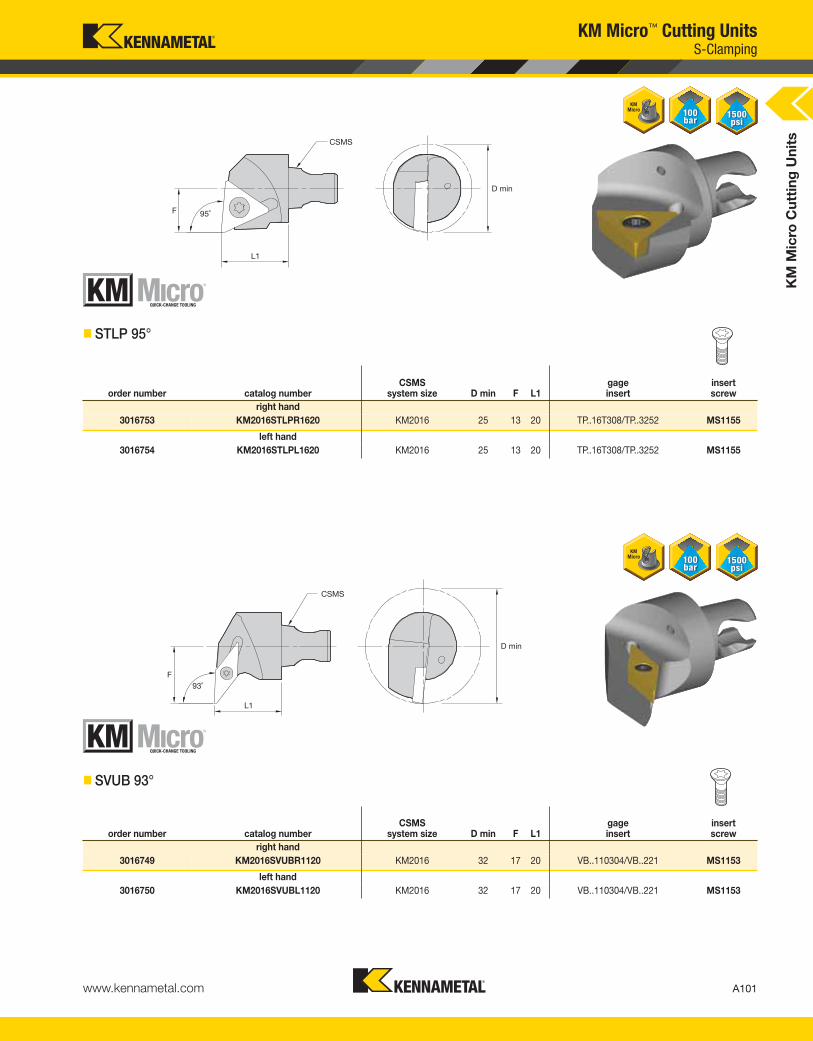
KM
Mic
ro C
utt
ing
Un
its
A101www.kennametal.com
KM Micro™ Cutting Units
� STLP 95°
order number catalog numberCSMS
system size D min F L1gageinsert
insert screw
right hand
3016753 KM2016STLPR1620 KM2016 25 13 20 TP..16T308/TP..3252 MS1155
left hand
3016754 KM2016STLPL1620 KM2016 25 13 20 TP..16T308/TP..3252 MS1155
� SVUB 93°
order number catalog numberCSMS
system size D min F L1gageinsert
insert screw
right hand
3016749 KM2016SVUBR1120 KM2016 32 17 20 VB..110304/VB..221 MS1153
left hand
3016750 KM2016SVUBL1120 KM2016 32 17 20 VB..110304/VB..221 MS1153
S-Clamping
KEN_TOOLINGSYSTEMS11_A100_A101.qxp:WIDIA 9:32 AM Page A101

KM
Mic
ro C
utt
ing
Un
its
A102 www.kennametal.com
KM Micro™ Cutting UnitsTop Notch™ Threading and Grooving
� NE
order number catalog numberCSMS
system size D min F L1gageinsert clamp
socket-headcap screw
right hand
3016751 KM2016NER220 KM2016 25 13 20 NG2L CM183 MS1200
left hand
3016752 KM2016NEL220 KM2016 25 13 20 NG2R CM182 MS1200
KEN_TOOLINGSYSTEMS11_A102_A103.qxp:WIDIA 9:32 AM Page A102

KM
Mic
ro I
nte
rna
l C
utt
ing
Un
its
A103www.kennametal.com
KM Micro™ Internal Cutting Units
� SCLD-S 95°
order number catalog numberCSMS
system size D min D2 F L1 L4gageinsert
insert screw
right hand
2253213 KM1612S0424SCLDRS4S KM1612 4,77 4,22 2,42 24 17 CD..S4T002/CD..120605 CC09
2253215 KM1612S0528SCLDRS4S KM1612 5,78 5,16 2,95 28 21 CD..S4T002/CD..120605 CC11
2253217 KM1612S0633SCLDRS4S KM1612 7,09 6,20 3,73 33 25 CD..S4T002/CD..120605 CC11
left hand
2253214 KM1612S0424SCLDLS4S KM1612 4,77 4,22 2,40 24 17 CD..S4T002/CD..120605 CC09
2253216 KM1612S0528SCLDLS4S KM1612 5,78 5,16 2,95 28 21 CD..S4T002/CD..120605 CC11
2253218 KM1612S0633SCLDLS4S KM1612 7,09 6,20 3,73 33 25 CD..S4T002/CD..120605 CC11
� SCLD-T 95°
order number catalog numberCSMS
system size D min D2 F L1 L4gageinsert
insert screw
right hand
2253219 KM1612S0424SCLDRS4T KM1612 4,77 4,22 2,40 24 17 CD..S4T002/CD..120605 CC09
2253221 KM1612S0528SCLDRS4T KM1612 5,78 5,16 2,95 28 21 CD..S4T002/CD..120605 CC11
2253223 KM1612S0633SCLDRS4T KM1612 7,09 6,20 3,73 33 25 CD..S4T002/CD..120605 CC11
left hand
2253220 KM1612S0424SCLDLS4T KM1612 4,77 4,22 2,40 24 17 CD..S4T002/CD..120605 CC09
2253222 KM1612S0528SCLDLS4T KM1612 5,78 5,16 2,95 28 21 CD..S4T002/CD..120605 CC11
2253224 KM1612S0633SCLDLS4T KM1612 7,09 6,20 3,73 33 25 CD..S4T002/CD..120605 CC11
S-Clamping
KEN_TOOLINGSYSTEMS11_A102_A103.qxp:WIDIA 9:32 AM Page A103

KM
Mic
ro I
nte
rna
l C
utt
ing
Un
its
A104 www.kennametal.com
KM Micro™ Internal Cutting Units
� SGFP-S 90°
order number catalog numberCSMS
system size D min D2 F L1 L4gageinsert
insert screw
right hand
2253225 KM1612S0633SGFPR05S KM1612 9,14 6,6 5,58 33 26,4 GP..050102/GP.505 CT15
2253227 KM1612S0840SGFPR05S KM1612 10,72 8,2 6,37 40 33,0 GP..050102/GP.505 CT15
left hand
2253226 KM1612S0633SGFPL05S KM1612 9,14 6,6 5,58 33 26,4 GP..050102/GP..12105 CT15
2253228 KM1612S0840SGFPL05S KM1612 10,72 8,2 6,37 40 33,0 GP..050102/GP..12105 CT15
� SGFP-T 90°
order number catalog numberCSMS
system size D min D2 F L1 L4gageinsert
insert screw
right hand
2253229 KM1612S0633SGFPR05T KM1612 9,14 6,6 5,58 33 26,4 GP..050102/GP.505 CT15
2253231 KM1612S0840SGFPR05T KM1612 10,72 8,2 6,37 40 33,0 GP..050102/GP.505 CT15
left hand
2253230 KM1612S0633SGFPL05T KM1612 9,14 6,6 5,58 33 26,4 GP..050102/GP.505 CT15
2253232 KM1612S0840SGFPL05T KM1612 10,72 8,2 6,37 40 33,0 GP..050102/GP.505 CT15
S-Clamping
KEN_TOOLINGSYSTEMS11_A104_A105.qxp:WIDIA 12:38 PM Page A104
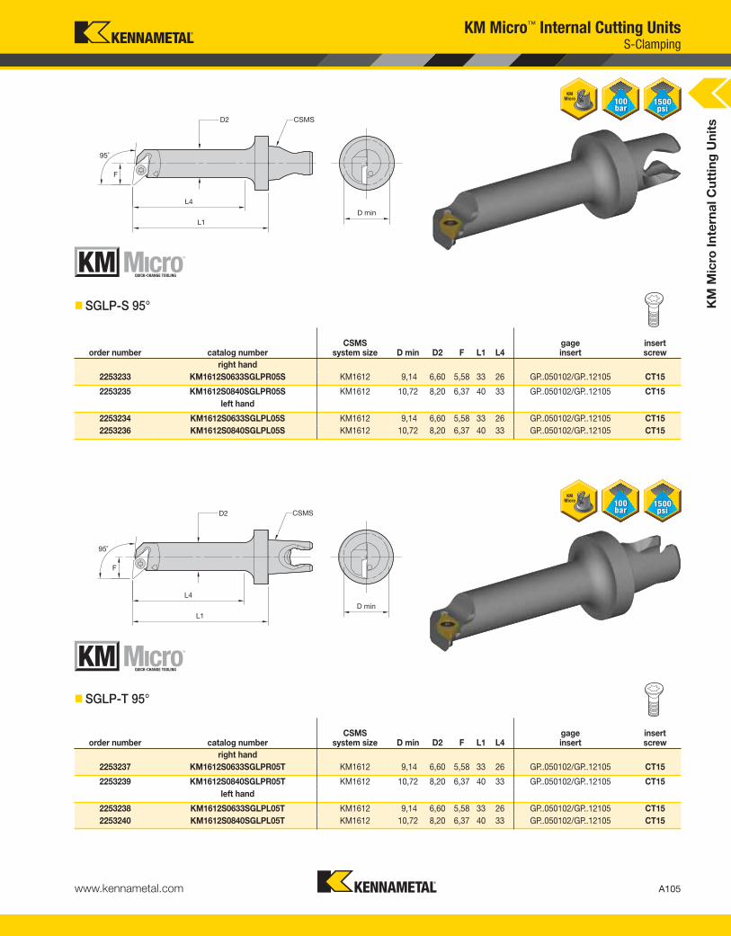
KM
Mic
ro I
nte
rna
l C
utt
ing
Un
its
A105www.kennametal.com
KM Micro™ Internal Cutting Units
order number catalog numberCSMS
system size D min D2 F L1 L4gageinsert
insert screw
right hand
2253233 KM1612S0633SGLPR05S KM1612 9,14 6,60 5,58 33 26 GP..050102/GP..12105 CT15
2253235 KM1612S0840SGLPR05S KM1612 10,72 8,20 6,37 40 33 GP..050102/GP..12105 CT15
left hand
2253234 KM1612S0633SGLPL05S KM1612 9,14 6,60 5,58 33 26 GP..050102/GP..12105 CT15
2253236 KM1612S0840SGLPL05S KM1612 10,72 8,20 6,37 40 33 GP..050102/GP..12105 CT15
order number catalog numberCSMS
system size D min D2 F L1 L4gageinsert
insert screw
right hand
2253237 KM1612S0633SGLPR05T KM1612 9,14 6,60 5,58 33 26 GP..050102/GP..12105 CT15
2253239 KM1612S0840SGLPR05T KM1612 10,72 8,20 6,37 40 33 GP..050102/GP..12105 CT15
left hand
2253238 KM1612S0633SGLPL05T KM1612 9,14 6,60 5,58 33 26 GP..050102/GP..12105 CT15
2253240 KM1612S0840SGLPL05T KM1612 10,72 8,20 6,37 40 33 GP..050102/GP..12105 CT15
� SGLP-T 95°
� SGLP-S 95°
S-Clamping
KEN_TOOLINGSYSTEMS11_A104_A105.qxp:WIDIA 12:38 PM Page A105
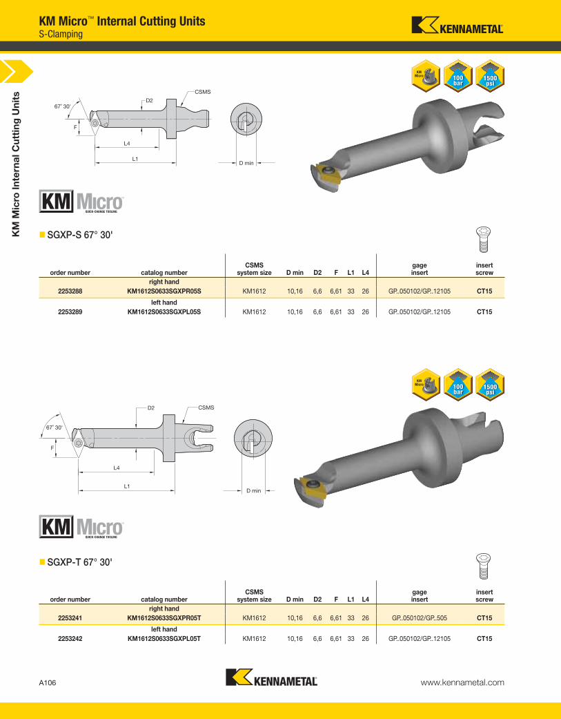
KM
Mic
ro I
nte
rna
l C
utt
ing
Un
its
A106 www.kennametal.com
KM Micro™ Internal Cutting Units
order number catalog numberCSMS
system size D min D2 F L1 L4gageinsert
insert screw
right hand
2253288 KM1612S0633SGXPR05S KM1612 10,16 6,6 6,61 33 26 GP..050102/GP..12105 CT15
left hand
2253289 KM1612S0633SGXPL05S KM1612 10,16 6,6 6,61 33 26 GP..050102/GP..12105 CT15
� SGXP-T 67° 30'
order number catalog numberCSMS
system size D min D2 F L1 L4gageinsert
insert screw
right hand
2253241 KM1612S0633SGXPR05T KM1612 10,16 6,6 6,61 33 26 GP..050102/GP..505 CT15
left hand
2253242 KM1612S0633SGXPL05T KM1612 10,16 6,6 6,61 33 26 GP..050102/GP..12105 CT15
� SGXP-S 67° 30'
S-Clamping
KEN_TOOLINGSYSTEMS11_A106_A107.qxp:WIDIA 9:32 AM Page A106

KM
Mic
ro I
nte
rna
l C
utt
ing
Un
its
A107www.kennametal.com
� SGJP-S 92°
order number catalog numberCSMS
system size D min D2 F L1 L4gageinsert
insert screw
right hand
2253243 KM1612S0840SGJPR05S KM1612 8,68 8,20 4,34 40 33 GP..050102/GP..12105 CT11
2253247 KM1612S0945SGJPR05S KM1612 9,75 9,25 4,89 45 38 GP..050102/GP..12105 CT11
left hand
2253244 KM1612S0840SGJPL05S KM1612 8,68 8,20 4,34 40 33 GP..050102/GP..12105 CT11
2253248 KM1612S0945SGJPL05S KM1612 9,75 9,25 4,89 45 38 GP..050102/GP..12105 CT11
KM Micro™ Internal Cutting Units
� SGJP-T 92°
order number catalog numberCSMS
system size D min D2 F L1 L4gageinsert
insert screw
right hand
2253249 KM1612S0840SGJPR05T KM1612 8,68 8,20 4,34 40 33 GP..050102/GP..12105 CT11
2253251 KM1612S0945SGJPR05T KM1612 9,75 9,25 4,89 45 38 GP..050102/GP..12105 CT11
left hand
2253250 KM1612S0840SGJPL05T KM1612 8,68 8,20 4,34 40 33 GP..050102/GP..12105 CT11
2253252 KM1612S0945SGJPL05T KM1612 9,75 9,25 4,89 45 38 GP..050102/GP..12105 CT11
S-Clamping
KEN_TOOLINGSYSTEMS11_A106_A107.qxp:WIDIA 9:32 AM Page A107

KM
Mic
ro I
nte
rna
l C
utt
ing
Un
its
A108 www.kennametal.com
KM Micro™ Internal Cutting Units
� STLD-S 95°
order number catalog numberCSMS
system size D min D2 F L1 L4gageinsert
insert screw
right hand
2253253 KM1612S0633STLDR07S KM1612 7,06 6,2 3,71 33 26 TD..07S1202/TD..130805 FC11
2253255 KM1612S0840STLDR07S KM1612 9,14 8,2 4,80 40 33 TD..07S1202/TD..130805 FC11
left hand
2253254 KM1612S0633STLDL07S KM1612 7,06 6,2 3,71 33 26 TD..07S1202/TD..130805 FC11
2253256 KM1612S0840STLDL07S KM1612 9,14 8,2 4,80 40 33 TD..07S1202/TD..130805 FC11
� STLD-T 95°
order number catalog numberCSMS
system size D min D2 F L1 L4gageinsert
insert screw
right hand
2253257 KM1612S0633STLDR07T KM1612 7,06 6,2 3,71 33 26 TD..07T1202/TD..12807505 FC11
2253259 KM1612S0840STLDR07T KM1612 9,14 8,2 4,80 40 33 TD..07T1202/TD..12807505 FC11
left hand
2253258 KM1612S0633STLDL07T KM1612 7,06 6,2 3,71 33 26 TD..07T1202/TD..12807505 FC11
2253260 KM1612S0840STLDL07T KM1612 9,14 8,2 4,80 40 33 TD..07T1202/TD..12807505 FC11
S-Clamping
KEN_TOOLINGSYSTEMS11_A108_A109.qxp:WIDIA 9:33 AM Page A108

KM
Mic
ro I
nte
rna
l C
utt
ing
Un
its
A109www.kennametal.com
order number catalog numberCSMS
system size D min D2 F L1 L4gageinsert
insert screw
right hand
2250067 KM1612S1046STLPR11T KM1612 11,15 10,21 5,79 46 41 TP..110202/TP..21505 QC21
2250069 KM2016S1046STLPR11T KM2016 11,15 10,21 5,79 46 41 TP..110202/TP..21505 QC21
2250071 KM2016S1358STLPR11T KM2016 14,25 12,95 7,52 58 52 TP..110202/TP..21505 QC21
left hand
2250068 KM1612S1046STLPL11T KM1612 11,15 10,21 5,79 46 41 TP..110202/TP..21505 QC21
2250070 KM2016S1046STLPL11T KM2016 11,15 10,21 5,79 46 41 TP..110202/TP..21505 QC21
2250072 KM2016S1358STLPL11T KM2016 14,25 12,95 7,53 58 52 TP..110202/TP..21505 QC21
order number catalog numberCSMS
system size D min D2 F L1 L4gageinsert
insert screw
right hand
2253261 KM1612S1046STLPR11S KM1612 11,15 10,21 5,79 46 41 TP..110202/TP..21505 QC21
2253263 KM2016S1046STLPR11S KM2016 11,15 10,21 5,79 46 41 TP..110202/TP..21505 QC21
2253265 KM2016S1358STLPR11S KM2016 14,25 12,95 7,52 58 52 TP..110202/TP..21505 QC21
left hand
2253262 KM1612S1046STLPL11S KM1612 11,15 10,21 5,79 46 41 TP..110202/TP..21505 QC21
2253264 KM2016S1046STLPL11S KM2016 11,15 10,21 5,79 46 41 TP..110202/TP..21505 QC21
2253266 KM2016S1358STLPL11S KM2016 14,25 12,95 7,52 58 52 TP..110202/TP..21505 QC21
� STLP-S 95°
KM Micro™ Internal Cutting Units
� STLP-T 95°
S-Clamping
KEN_TOOLINGSYSTEMS11_A108_A109.qxp:WIDIA 9:33 AM Page A109

KM
Mic
ro I
nte
rna
l C
utt
ing
Un
its
A110 www.kennametal.com
order number catalog numberCSMS
system size D min D2 F L1 L4gageinsert
insert screw
right hand
2250073 KM1612S0529SCXDRS KM1612 6,93 5,56 3,91 29 22 CD.50302R CC11
2250074 KM1612S0633SCXDRS KM1612 7,82 6,35 4,40 33 26 CD.50302R CC11
KM Micro™ Internal Cutting Units
order number catalog numberCSMS
system size D min D2 F L1 L4gageinsert
insert screw
right hand
2250037 KM1612S0529SCXDRT KM1612 6,93 5,56 3,91 29 22 CD..40762/CD.120302 CC11
2250038 KM1612S0633SCXDRT KM1612 7,82 6,35 4,40 33 26 CD..40762/CD.120302 CC11
� SCXD-S 100°
� SCXD-T 100°
S-Clamping
KEN_TOOLINGSYSTEMS11_A110_A111.qxp:WIDIA 9:33 AM Page A110

order number catalog numberCSMS
system size D min D2 F L1 L4gageinsert
insert screw
right hand
2250063 KM1612S1046SCXPRT KM1612 11,10 10,21 5,75 46 41 CP..06T102/CP..21205 QC15
2250065 KM2016S1046SCXPRT KM2016 11,10 10,21 5,75 46 41 CP..06T102/CP..21205 QC15
left hand
2250064 KM1612S1046SCXPLT KM1612 11,10 10,21 5,75 46 41 CP..06T102/CP..21205 QC15
2250066 KM2016S1046SCXPLT KM2016 11,10 10,21 5,75 46 41 CP..06T102/CP..21205 QC15
KM
Mic
ro I
nte
rna
l C
utt
ing
Un
its
A111www.kennametal.com
order number catalog numberCSMS
system size D min D2 F L1 L4gageinsert
insert screw
right hand
2250039 KM1612S1046SCXPRS KM1612 11,10 10,21 5,75 46 41 CP..06T102/CP..21205 QC15
2250041 KM2016S1046SCXPRS KM2016 11,10 10,21 5,75 46 41 CP..06T102/CP..21205 QC15
left hand
2250040 KM1612S1046SCXPLS KM1612 11,10 10,21 5,75 46 41 CP..06T102/CP..21205 QC15
2250042 KM2016S1046SCXPLS KM2016 11,10 10,21 5,75 46 41 CP..06T102/CP..21205 QC15
KM Micro™ Internal Cutting Units
� SCXP-S 95°
� SCXP-T 95°
S-Clamping
KEN_TOOLINGSYSTEMS11_A110_A111.qxp:WIDIA 9:33 AM Page A111
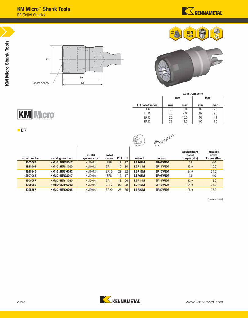
KM
Mic
ro S
ha
nk
To
ols
A112 www.kennametal.com
collet series
KM Micro™ Shank ToolsER Collet Chucks
� ER
order number catalog numberCSMS
system sizecolletseries D11 L1 locknut wrench
counterbore collet
torque (Nm)
straight collet
torque (Nm)
2607067 KM1612ER08017 KM1612 ER8 12 17 LER08M ER08WEM 4.8 4.0
1925844 KM1612ER11020 KM1612 ER11 16 20 LER11M ER11WEM 12.0 16.0
1925845 KM1612ER16032 KM1612 ER16 22 32 LER16M ER16WEM 24.0 24.0
2607068 KM2016ER08017 KM2016 ER8 12 17 LER08M ER08WEM 4.8 4.0
1898057 KM2016ER11020 KM2016 ER11 16 20 LER11M ER11WEM 12.0 16.0
1898058 KM2016ER16032 KM2016 ER16 22 32 LER16M ER16WEM 24.0 24.0
1925857 KM2016ER20035 KM2016 ER20 28 35 LER20M ER20WEM 28.0 28.0
Collet Capacity
mm inch
ER collet series min max min max
ER8 0,5 5,0 .02 .20
ER11 0,5 7,0 .02 .28
ER16 0,5 10,0 .02 .41
ER20 0,5 13,0 .02 .50
(continued)
KEN_TOOLINGSYSTEMS11_A112_A113.qxp:WIDIA 9:33 AM Page A112

KM
Mic
ro S
ha
nk
To
ols
A113www.kennametal.com
collet series
� ER-C
order number catalog numberCSMS
system sizecolletseries D11 L1 locknut wrench
counterbore collet
torque (Nm)
straight collet
torque (Nm)
3741453 KM2016ER08025C KM2016 ER08 12 25 LER08M ER08WEM 4.8 4.0
3741454 KM2016ER11030C KM2016 ER11 16 30 LER11M ER11WEM 12.0 16.0
3741455 KM2016ER16040C KM2016 ER16 22 40 LER16M ER16WEM 24.0 24.0
3741456 KM2016ER20045C KM2016 ER20 28 45 LER20M ER20WEM 28.0 28.0
NOTE: Collet must be loaded into locknut first. Before loading into the chuck body, insert the cutting tool, then tighten to the recommended tightening torque.Collet chuck technical section, see page M98.Supplied with locknut. Locknut wrench must be ordered separately.Interchangeable coolant-style locknuts and coolant disks are available and must be ordered separately; see page L19.ER standard straight-bore collets, see page J50.ER tap collets, see pages J58-J59.ER TCT tension-only tap collets, see page J60.
(ER continued)
KM Micro™ Shank ToolsER Collet Chucks
KEN_TOOLINGSYSTEMS11_A112_A113.qxp:WIDIA 9:33 AM Page A113
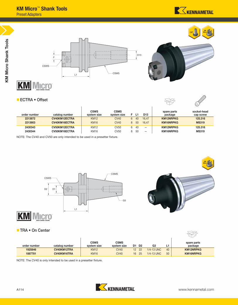
KM
Mic
ro S
ha
nk
To
ols
A114 www.kennametal.com
L1
D13
CSWS
CSMS
F
KM Micro™ Shank ToolsPreset Adapters
NOTE: The CV40 and CV50 are only intended to be used in a presetter fixture.
order number catalog numberCSWS
system sizeCSMS
system size D1 D2 G3 L1spare parts
package
1925846 CV40KM12TRA KM12 CV40 12 22 1/4-13 UNC 40 KM12NRPKG
1887781 CV40KM16TRA KM16 CV40 16 25 1/4-13 UNC 50 KM16NRPKG
NOTE: The CV40 is only intended to be used in a presetter fixture.
order number catalog numberCSWS
system sizeCSMS
system size F L1 D13spare parts
packagesocket-headcap screw
2213872 CV40KM12ECTRA KM12 CV40 6 40 16,47 KM12NRPKG 125.316
2213903 CV40KM16ECTRA KM16 CV40 8 50 16,47 KM16NRPKG MS319
2430343 CV50KM12ECTRA KM12 CV50 6 40 — KM12NRPKG 125.316
2430344 CV50KM16ECTRA KM16 CV50 8 50 — KM16NRPKG MS319
� ECTRA • Offset
� TRA • On Center
KEN_TOOLINGSYSTEMS11_A114_A115.qxp:WIDIA 9:33 AM Page A114

KM
Mic
ro S
ha
nk
To
ols
A115www.kennametal.com
• Machinable front 38–42 HRC.
order number catalog numberCSMS
system size D2 L1 kg lbs
1925849 KM12BN3133 KM12 31 33 0,19 .43
3836822 KM1612BN1650 KM1612 16 50 0,08 .18
3836820 KM1612BN2430 KM1612 24 30 0,11 .23
1851739 KM16BN3740 KM16 37 40 0,34 .74
3836821 KM2016BN2060 KM2016 20 60 0,15 .34
3836819 KM2016BN3035 KM2016 31 35 0,20 .44
KM Micro™ Shank Tools
order number catalog numberCSMS
system size D2 L1 L13 kg lbs
2417677 KM12GB1620 KM12 16 20 19 0,04 .08
2417676 KM16GB2020 KM16 20 20 20 0,06 .13
� BN • Blank
� GB • Gage Bar
Blanks • Gage Bars
KEN_TOOLINGSYSTEMS11_A114_A115.qxp:WIDIA 9:33 AM Page A115

KM
Mic
ro S
ha
nk
To
ols
A116 www.kennametal.com
KM Micro™ Shank Tools
� TIM • Timing Head
order number catalog numberCSMS
system size D2 L1 H2
1925847 KM12TIM0915 KM12 31 15 9
1886774 KM16TIM1420 KM16 37 20 14
Timing Heads
KEN_TOOLINGSYSTEMS11_A116_A117.qxp:WIDIA 9:33 AM Page A116

KM
Mic
ro S
hank
To
ols
A117www.kennametal.com
order number catalog numberCSWS
system size B1 B2 H2 H3 L1spare parts
package kg lbs2430347 KM12TB KM12 32 64 64 32 50 KM12NRPKG 1,18 2.602430348 KM16TB KM16 32 64 64 32 50 KM16NRPKG 1,13 2.49
KM Micro™ Shank Tools
� P • Plug
order number catalog numberCSMS
system size D2 L11925848 KM12P KM12 12 53397220 KM1612P KM1612 16 5
1851741 KM16P KM16 16 53397219 KM2016P KM2016 20 5
Tumble Blocks • Plugs
� TB • Tumble Block
KEN_TOOLINGSYSTEMS11_A116_A117.qxp:WIDIA 2:04 PM Page A117

Features and Benefits
Features• KM Mini is a compact quick-change tooling system.
• Face and taper surface contact between the cutting unit and clamping units.
• Mating taper clamping surfaces.
• Square shank adapters for standard tool blocks.
Functions• The mechanism design consists of two components:
the torque screw and the wedge nut.
• Precise and repeatable cutting edge position is in both directions of cut
• Maximum possible surface contact between the clamping mechanism and the cutting unit.
• Designed around a short 10:1 tapered shank.
• The taper is self-centering to promote easy tool loading and unloading.
Primary ApplicationThe KM Mini coupling offers a very rigid joint with a high degree of repeatability while maintaining a very compact envelope. This permits a high degree of versatility without sacrificing cutting performance.
KM™ Mini • Quick Change Tooling System
A118 www.kennametal.com
KEN_TOOLINGSYSTEMS11_A118_A119.qxp:WIDIA 9:39 AM Page A118

Advantages• Reduce downtime, increase productivity.
• Replaces conventional square-shank tooling.
• No machine modifications required.
• KM™ Mini is ideal for machines up to 30 hp (22 kW).
A119www.kennametal.com
KEN_TOOLINGSYSTEMS11_A118_A119.qxp:WIDIA 9:39 AM Page A119

CClamping
Unit
NVersion
20System
Size
KMKennametal
Modular
KM20NCM2020100
How Do Catalog Numbers Work?Each character in our catalog number signifies a specific trait of thatproduct. Use the following key columns and corresponding imagesto easily identify which attributes apply.
MControl
A120 www.kennametal.com
KM™ Mini Clamping UnitsClamping Units for O.D. and I.D. Applications Catalog Numbering System
KM™ Mini Quick Change
tooling system
20 = 20 x 20mm
26 = 25 x 25mm
N = Neutral
L = Left-hand version
R = Right-hand version
M = Manual
A = Automatic
KEN_TOOLINGSYSTEMS11_A120_A121.qxp:WIDIA 9:39 AM Page A120
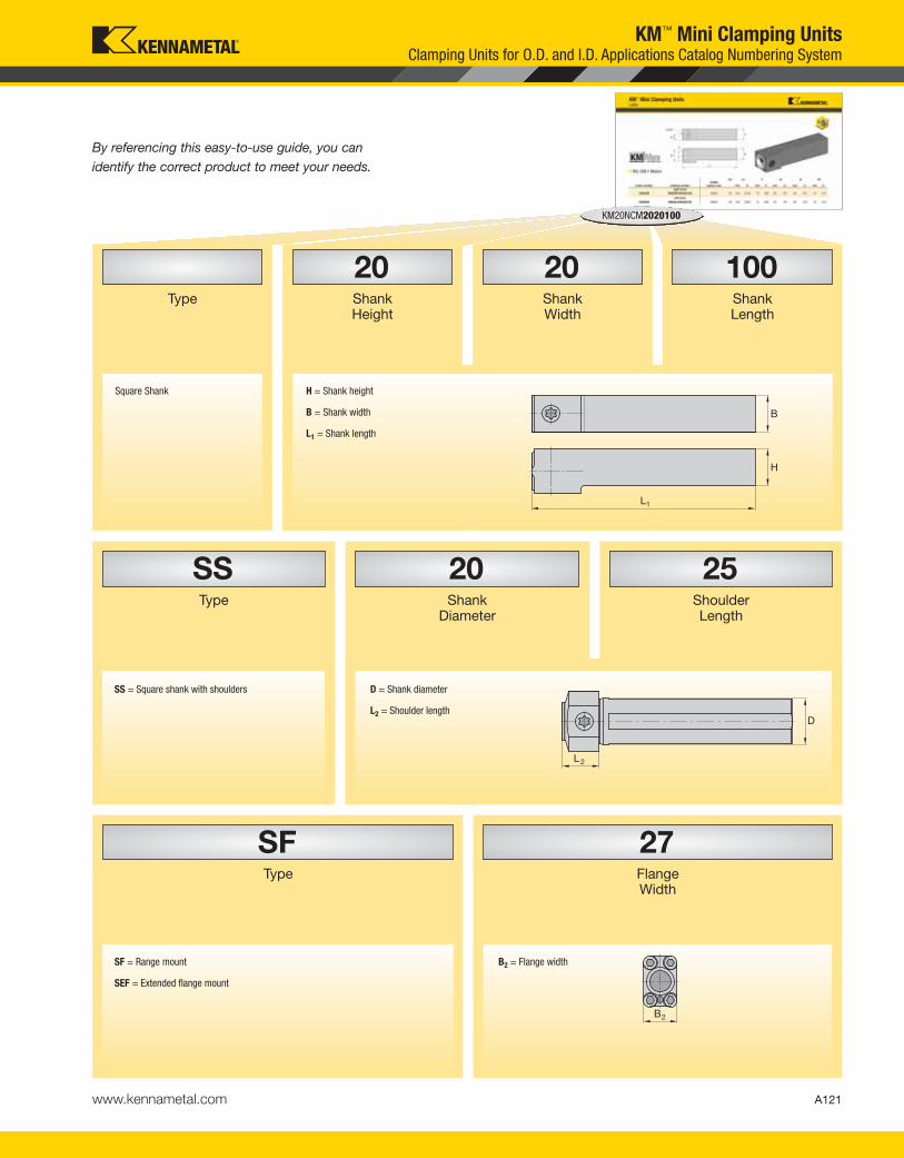
A121www.kennametal.com
KM™ Mini Clamping UnitsClamping Units for O.D. and I.D. Applications Catalog Numbering System
100Shank Length
20Shank Width
20Shank Height
Type
KM20NCM2020100
25Shoulder Length
20Shank
Diameter
SSType
By referencing this easy-to-use guide, you can
identify the correct product to meet your needs.
27Flange Width
SFType
H = Shank height
B = Shank width
L1 = Shank length
SS = Square shank with shoulders
SF = Range mount
SEF = Extended flange mount
B2 = Flange width
D = Shank diameter
L2 = Shoulder length
Square Shank
B
H
L1
L2
D
B2
KEN_TOOLINGSYSTEMS11_A120_A121.qxp:WIDIA 9:39 AM Page A121

KM
Min
i C
lam
pin
g U
nit
s
A122 www.kennametal.com
L1 F B H H1
order number catalog numberCSWS
system size
D1
mm in mm in mm in mm in mm in
right hand
3482938 KM20RCM2020100 KM20 20 100 3.937 13 .492 20 .787 20 .787 10 .413
left hand
3482939 KM20LCM2020100 KM20 20 100 3.937 13 .492 20 .787 20 .787 10 .413
L1 F B H H1
order number catalog numberCSWS
system size
D1
mm in mm in mm in mm in mm in
right hand
2385942 KM25RCM16382 KM25 25 97 3.819 16 .630 25 1.000 25 1.000 13 .508
2386034 KM25RCM16482 KM25 25 122 4.819 16 .630 25 1.000 25 1.000 13 .508
left hand
2386033 KM25LCM16382 KM25 25 97 3.819 16 .630 25 1.000 25 1.000 13 .508
2265206 KM25LCM16482 KM25 25 122 4.819 16 .630 25 1.000 25 1.000 13 .508
catalog numberspare parts
packagewrench size
actuation screw Nm ft. lbs.
right hand
KM20RCM2020100 KM20NAPKG 5mm 19-22 14-16
KM25RCM16382 KM25NAPKG 6mm 34-40 25-30
KM25RCM16482 KM25NAPKG 6 mm 34-40 25-30
left hand
KM20LCM2020100 KM20NAPKG 5mm 19-22 14-16
KM25LCM16382 KM25NAPKG 6mm 34-40 25-30
KM25LCM16482 KM25NAPKG 6mm 34-40 25-30
KM™ Mini Clamping UnitsLathe
� R/L CM • Metric
� R/L CM • Inch
� Spare Parts
NOTE: For torque wrench, see page L52–L53.
mm
mm
KEN_TOOLINGSYSTEMS11_A122_A123.qxp:WIDIA 9:39 AM Page A122

KM
Min
i C
lam
pin
g U
nit
s
A123www.kennametal.com
D1 L1 F H H1 B
order number catalog numberCSWS
system size mm mm in mm in mm in mm in mm in
2277879 KM25NCM2525120 KM25 25 120 4.724 16 .630 25 .984 13 .492 25 .984
D1 L1 F H H1 B
order number catalog numberCSWS
system size mm mm in mm in mm in mm in mm in
3482940 KM20NCM12352 KM20 20 89 3.516 13 .493 19 .750 10 .375 19 .750
catalog numberspare parts
packagewrench size
actuation screw Nm ft. lbs.
KM20NCM12352 KM20NAPKG 5mm 19-22 14-16
KM25NCM2525120 KM25NAPKG 6mm 34-40 25-30
KM™ Mini Clamping UnitsLathe
� NCM • Metric
� NCM • Inch
� Spare Parts
NOTE: For torque wrench, see page L52–L53.
KEN_TOOLINGSYSTEMS11_A122_A123.qxp:WIDIA 9:39 AM Page A123

KM
Min
i C
lam
pin
g U
nit
s
A124 www.kennametal.com
KM™ Mini Clamping UnitsLathe
� NCM-SS • Round Shank • Metric
NOTE: For torque wrench, see page L52–L53.
� Spare Parts
D D2 L L1
order number catalog numberCSWS
system size mm mm in mm in mm in mm in CS
3483039 KM2520NCMSS2025 KM2520 25 20 .787 28 1.102 90 3.543 25 .984 1/8-27 NPT
2594730 KM3225NCMSS2525 KM3225 32 25 .984 36 1.417 90 3.543 25 .984 1/4-18 NPT
2656549 KM3225NCMSS3225 KM3225 32 32 1.260 44 1.732 90 3.543 25 .984 1/4-18 NPT
2656550 KM3225NCMSS4025 KM3225 32 40 1.575 50 1.969 90 3.543 25 .984 1/4-18 NPT
catalog numberspare parts
packagewrench size
actuation screw Nm ft. lbs.
KM2520NCMSS2025 KM2520NRPKG 5mm 19-22 14-16
KM3225NCMSS2525 KM3225NRPKG 6mm 34-40 25-30
KM3225NCMSS3225 KM3225NRPKG 6mm 34-40 25-30
KM3225NCMSS4025 KM3225NRPKG 6mm 34-40 25-30
� NCM-SS • Round Shank • Inch
D1 D D2 L L1
order number catalog numberCSWS
system size mm mm in mm in mm in mm in CS
3483040 KM2520NCMSS12098 KM2520 25 19 .750 28 1.102 90 3.543 25 .984 1/4-18 NPT
2594729 KM3225NCMSS16098 KM3225 32 25 1.000 36 1.417 90 3.543 25 .984 1/4-18 NPT
2656547 KM3225NCMSS20098 KM3225 32 32 1.250 44 1.732 90 3.543 25 .984 1/4-18 NPT
2656548 KM3225NCMSS24098 KM3225 32 38 1.500 50 1.969 90 3.543 25 .984 1/4-18 NPT
� Spare Parts
catalog numberspare parts
packagewrench size
actuation screw Nm ft. lbs.
KM2520NCMSS12098 KM2520NRPKG 5mm 19-22 14-16
KM3225NCMSS16098 KM3225NRPKG 6mm 34-40 25-30
KM3225NCMSS20098 KM3225NRPKG 6mm 34-40 25-30
KM3225NCMSS24098 KM3225NRPKG 6mm 34-40 25-30
D1
KEN_TOOLINGSYSTEMS11_A124_A125.qxp:WIDIA 9:39 AM Page A124

KM
Min
i C
lam
pin
g U
nit
s
A125www.kennametal.com
KM™ Mini Clamping UnitsLathe
� NCM-S • Round Shank • Metric
� Spare Parts
� NCM-S • Round Shank • Inch
� Spare Parts
D L L2
order number catalog numberCSWS
system size mm mm in mm in mm in CS
3483037 KM2520NCMS25 KM2520 25 25 .984 150 5.906 20 .787 1/4-18 NPT
2541837 KM3225NCMS32 KM3225 32 32 1.260 220 8.661 25 .984 1/4-18 NPT
catalog numberspare parts
packagewrench size
actuation screw Nm
KM2520NCMS25 KM2520NRPKG 5mm 19-22
KM3225NCMS32 KM3225NRPKG 6mm 34-40
D1 D L L2
order number catalog numberCSWS
system size mm mm in mm in mm in CS
3483038 KM2520NCMS16 KM2520 25 25 1.000 153 6.016 20 .787 1/4-18 NPT
2541835 KM3225NCMS20 KM3225 32 32 1.250 171 6.750 25 .984 1/4-18 NPT
catalog numberspare parts
packagewrench size
actuation screw ft. lbs.
KM2520NCMS16 KM2520NRPKG 5mm 14-16
KM3225NCMS20 KM3225NRPKG 6mm 25-30
NOTE: For torque wrench, see page L52–L53.
D1
KEN_TOOLINGSYSTEMS11_A124_A125.qxp:WIDIA 9:39 AM Page A125

KM
Min
i C
lam
pin
g U
nit
s
A126 www.kennametal.com
KM™ Mini Clamping UnitsLathe
� ECM-S • Round Shank, Offset • Metric
� Spare Parts
� ECM-S • Round Shank, Offset • Inch
� Spare Parts
D1 D L L2 F
order number catalog numberCSWS
system size mm mm in mm in mm in mm in CS
2541836 KM3225ECMS40 KM3225 32 40 1.575 270 10.630 35 1.378 4 .157 1/4-18 NPT
catalog numberspare parts
packagewrench size
actuation screw Nm
KM3225ECMS40 KM3225NRPKG 6mm 34-40
D1 D L L2 F
order number catalog numberCSWS
system size mm mm in mm in mm in mm in CS
2541730 KM3225ECMS24 KM3225 32 38 1.500 254 10.000 35 1.378 3 .120 1/4-18 NPT
catalog numberspare parts
packagewrench size
actuation screw ft. lbs.
KM3225ECMS24 KM3225NRPKG 6mm 25-30
NOTE: For torque wrench, see page L52–L53.
KEN_TOOLINGSYSTEMS11_A126_A127.qxp:WIDIA 9:39 AM Page A126

KM
Min
i C
lam
pin
g U
nit
s
A127www.kennametal.com
KM™ Mini Clamping UnitsLathe
� NCM-SF • Flange Mount
� Spare Parts
NOTE: For torque wrench, see page L52–L53.For mounting controls, see page M70.
D1 D L L1 B2 H2
order number catalog numberCSWS
system size mm mm in mm in mm in mm in mm in
3482941 KM20NCMSF2434 KM20 20 18 .709 24 .945 18 .709 24 .945 33 1.299
2386035 KM25NCMSF3140 KM25 25 24 .945 28 1.102 20 .787 31 1.221 39 1.535
catalog numberspare parts
packagewrench size
actuation screw Nm ft. lbs.
KM20NCMSF2434 KM2520NRPKG 5mm 19-22 14-16
KM25NCMSF3140 KM25NRPKG 6mm 34-40 25-30
KEN_TOOLINGSYSTEMS11_A126_A127.qxp:WIDIA 9:39 AM Page A127
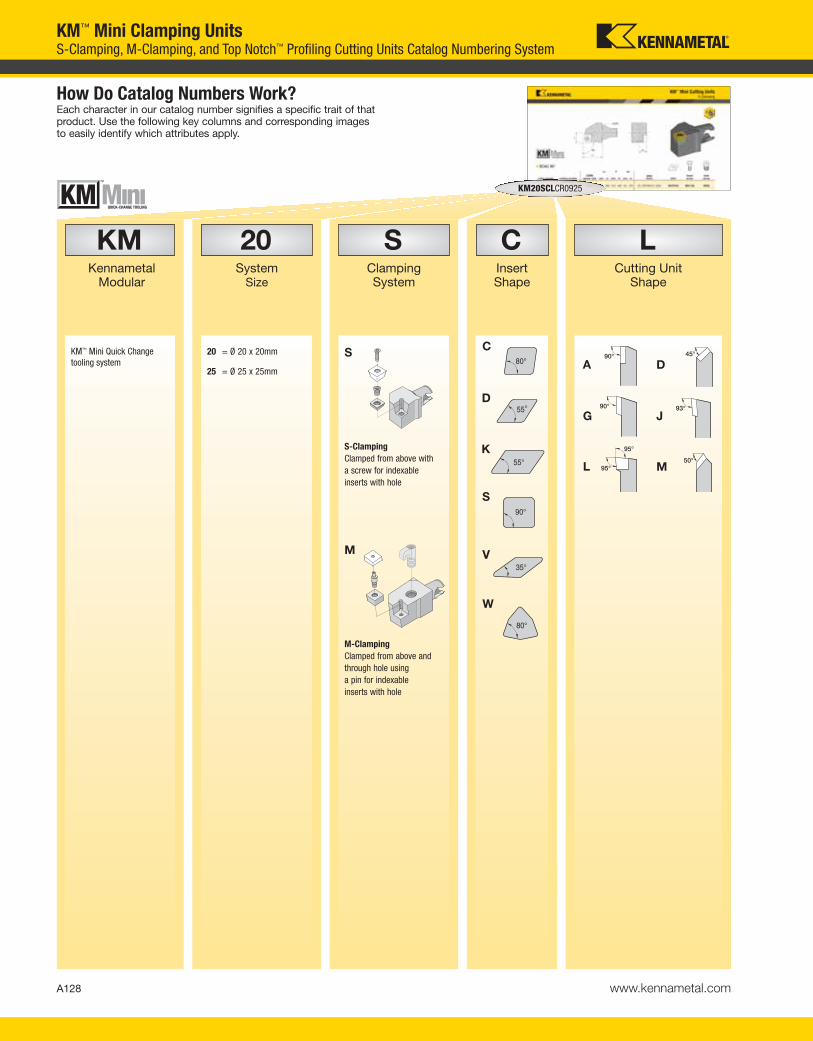
A128 www.kennametal.com
KM™ Mini Clamping UnitsS-Clamping, M-Clamping, and Top Notch™ Profiling Cutting Units Catalog Numbering System
KMKennametal
Modular
KM20SCLCR0925
How Do Catalog Numbers Work?Each character in our catalog number signifies a specific trait of thatproduct. Use the following key columns and corresponding imagesto easily identify which attributes apply.
KM™ Mini Quick Change
tooling system
20System
Size
20 = Ø 20 x 20mm
25 = Ø 25 x 25mm
SClampingSystem
S
S-Clamping
Clamped from above with
a screw for indexable
inserts with hole
CInsertShape
LCutting Unit
Shape
M
M-Clamping
Clamped from above and
through hole using
a pin for indexable
inserts with hole
C
S
D
K
L
D
J
M
A
G
V
W
KEN_TOOLINGSYSTEMS11_A128_A129.qxp:WIDIA 9:40 AM Page A128

A129www.kennametal.com
KM™ Mini Clamping UnitsS-Clamping, M-Clamping, and Top Notch™ Profiling Cutting Units Catalog Numbering System
25Gage
Length
09Insert Size
RDirection
CClearance
Angle
KM20SCLCR0925
By referencing this easy-to-use guide, you can
identify the correct product to meet your needs.
l
CDV
l
K
l
S
l
Tl
W
B
C
P
N
L = Left-hand cutting unit
L1 = Gage length
R = Right-hand cutting unit
N = Neutral cutting unit
KEN_TOOLINGSYSTEMS11_A128_A129.qxp:WIDIA 9:40 AM Page A129
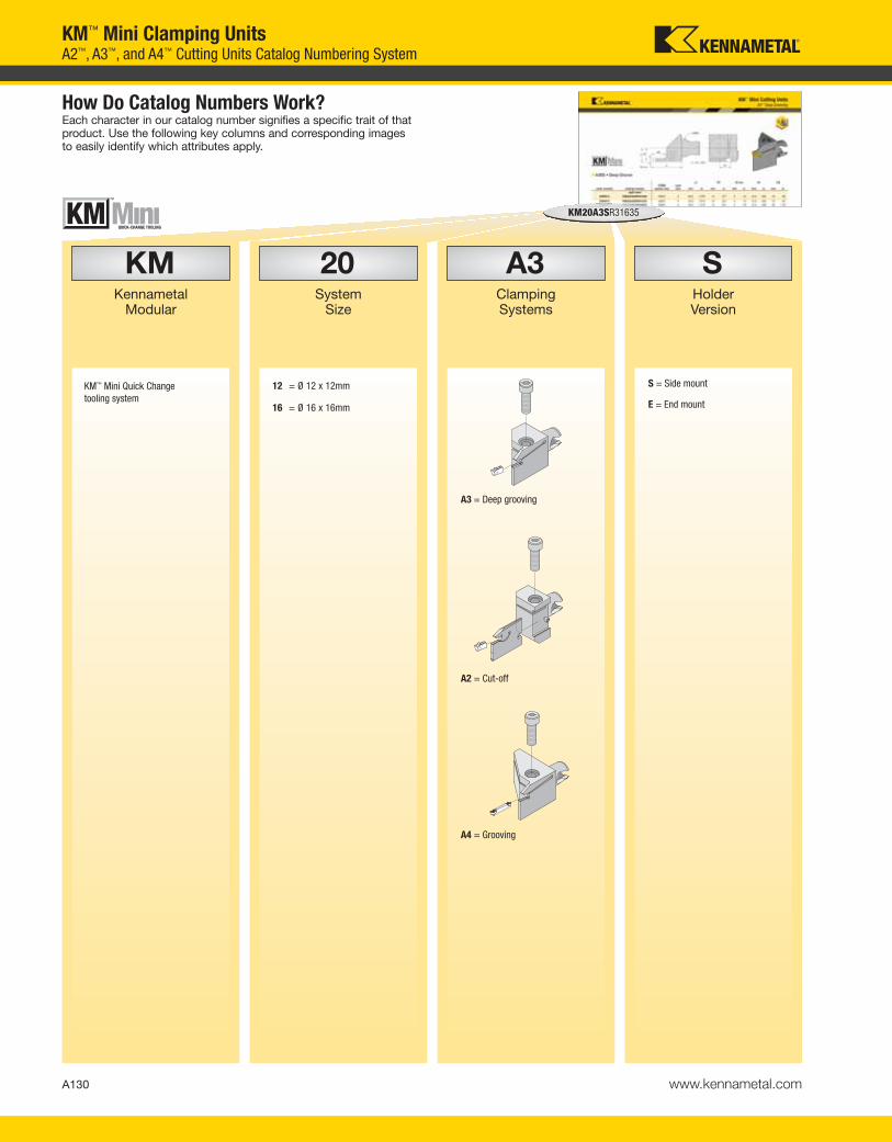
A130 www.kennametal.com
SHolder Version
A3Clamping Systems
20System
Size
KMKennametal
Modular
KM20A3SR31635
How Do Catalog Numbers Work?Each character in our catalog number signifies a specific trait of thatproduct. Use the following key columns and corresponding imagesto easily identify which attributes apply.
KM™ Mini Quick Change
tooling system
12 = Ø 12 x 12mm
16 = Ø 16 x 16mm
KM™ Mini Clamping UnitsA2™, A3™, and A4™ Cutting Units Catalog Numbering System
S = Side mount
E = End mount
A3 = Deep grooving
A4 = Grooving
A2 = Cut-off
KEN_TOOLINGSYSTEMS11_A130_A131.qxp:WIDIA 9:40 AM Page A130

A131www.kennametal.com
35Gage
Length
16Cutting Depth
3Insert
Seat Size
RDirection
KM20A3SR31635
By referencing this easy-to-use guide, you can
identify the correct product to meet your needs.
R = Right hand
07 = 7mm
11 = 11mm
16 = 16mm
L1 = Gage length
L = Left hand
KM™ Mini Clamping UnitsA2™, A3™, and A4™ Cutting Units Catalog Numbering System
insert
seat size
1
1B
2
2B
3
4
5
KEN_TOOLINGSYSTEMS11_A130_A131.qxp:WIDIA 9:40 AM Page A131

LSClamping Systems
20System
Size
KMKennametal
Modular
KM20LSSR1625
How Do Catalog Numbers Work?Each character in our catalog number signifies a specific trait of thatproduct. Use the following key columns and corresponding imagesto easily identify which attributes apply.
A132 www.kennametal.com
KM™ Mini Clamping UnitsLT Threading Cutting Units Catalog Numbering System
20 = Ø 20 x 20mm
25 = Ø 25 x 25mm
LT Threading = Clamped from above with a screw
KM™ Mini Quick Change
tooling system
KEN_TOOLINGSYSTEMS11_A132_A133.qxp:WIDIA 9:40 AM Page A132

25Gage
Length
16Insert Size
RDirection
SLocation
KM20LSSR1625
By referencing this easy-to-use guide, you can
identify the correct product to meet your needs.
A133www.kennametal.com
KM™ Mini Clamping UnitsLT Threading Cutting Units Catalog Numbering System
E = End mount
S = Side mount
L1 = Gage length
L = Left-hand cutting unit
R = Right-hand cutting unit
I
d
l = Cutting edge length
11 6,35
16 9,52
22 12,70
27 15,88
l d (IC)
KEN_TOOLINGSYSTEMS11_A132_A133.qxp:WIDIA 9:40 AM Page A133

KM
Min
i C
utt
ing
Un
its
A134 www.kennametal.com
KM™ Mini Cutting Units
� MCKN 75°
L1 F H1
order number catalog numberCSMS
system size mm in mm in mm ingageinsert shim
lock pin clamp
clampscrew
right hand
3487534 KM20MCKNR1225 KM20 25 .984 12,5 .492 9,5 .375 CN..120408/CN..432 ICSN432 KLM46 CKM20LP STCM11
2398793 KM25MCKNR1230 KM25 30 1.181 16,0 .630 12,5 .492 CN..120408/CN..432 ICSN433 KLM4615IP CKM20LP STCM1115IP
left hand
3487533 KM20MCKNL1225 KM20 25 .984 12,5 .492 9,5 .375 CN..120408/CN..432 ICSN432 KLM46 CKM20LP STCM11
2398794 KM25MCKNL1230 KM25 30 1.181 16,0 .630 12,5 .492 CN..120408/CN..432 ICSN433 KLM4615IP CKM20LP STCM1115IP
� MCLN 95°
L1 F H1
order number catalog numberCSMS
system size mm in mm in mm ingageinsert shim
lock pin clamp
clampscrew
right hand
3487520 KM20MCLNR0925 KM20 25 .984 12,5 .492 9,5 .375 CN..090308/CN..322 ICSN332 KLM34L CKM7LP STCM9
3487522 KM20MCLNR1225 KM20 25 .984 12,5 .492 9,5 .375 CN..120408/CN..432 ICSN432 KLM46 CKM20LP STCM11
2265207 KM25MCLNR1230 KM25 30 1.181 16,0 .630 12,5 .492 CN..120408/CN..432 ICSN433 KLM4615IP CKM20LP STCM1115IP
left hand
3487519 KM20MCLNL0925 KM20 25 .984 12,5 .492 9,5 .375 CN..090308/CN..322 ICSN332 KLM34L CKM7LP STCM9
3487521 KM20MCLNL1225 KM20 25 .984 12,5 .492 9,5 .375 CN..120408/CN..432 ICSN432 KLM46 CKM20LP STCM11
2398795 KM25MCLNL1230 KM25 30 1.181 16,0 .630 12,5 .492 CN..120408/CN..432 ICSN433 KLM4615IP CKM20LP STCM1115IP
M-Clamping
KEN_TOOLINGSYSTEMS11_A134_A135.qxp:WIDIA 9:41 AM Page A134
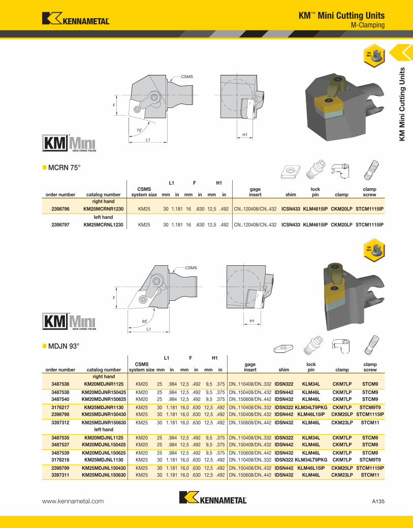
KM
Min
i C
utt
ing
Un
its
A135www.kennametal.com
KM™ Mini Cutting Units
� MCRN 75°
L1 F H1
order number catalog numberCSMS
system size mm in mm in mm ingageinsert shim
lock pin clamp
clampscrew
right hand
2398796 KM25MCRNR1230 KM25 30 1.181 16 .630 12,5 .492 CN..120408/CN..432 ICSN433 KLM4615IP CKM20LP STCM1115IP
left hand
2398797 KM25MCRNL1230 KM25 30 1.181 16 .630 12,5 .492 CN..120408/CN..432 ICSN433 KLM4615IP CKM20LP STCM1115IP
� MDJN 93°
L1 F H1
order number catalog numberCSMS
system size mm in mm in mm ingageinsert shim
lock pin clamp
clampscrew
right hand
3487536 KM20MDJNR1125 KM20 25 .984 12,5 .492 9,5 .375 DN..110408/DN..332 IDSN322 KLM34L CKM7LP STCM9
3487538 KM20MDJNR150425 KM20 25 .984 12,5 .492 9,5 .375 DN..150408/DN..432 IDSN442 KLM46L CKM7LP STCM9
3487540 KM20MDJNR150625 KM20 25 .984 12,5 .492 9,5 .375 DN..150608/DN..442 IDSN432 KLM46L CKM7LP STCM9
3176217 KM25MDJNR1130 KM25 30 1.181 16,0 .630 12,5 .492 DN..110408/DN..332 IDSN322 KLM34LT9PKG CKM7LP STCM9T9
2398798 KM25MDJNR150430 KM25 30 1.181 16,0 .630 12,5 .492 DN..150408/DN..432 IDSN442 KLM46L15IP CKM20LP STCM1115IP
3397312 KM25MDJNR150630 KM25 30 1.181 16,0 .630 12,5 .492 DN..150608/DN..442 IDSN432 KLM46L CKM23LP STCM11
left hand
3487535 KM20MDJNL1125 KM20 25 .984 12,5 .492 9,5 .375 DN..110408/DN..332 IDSN322 KLM34L CKM7LP STCM9
3487537 KM20MDJNL150425 KM20 25 .984 12,5 .492 9,5 .375 DN..150408/DN..432 IDSN442 KLM46L CKM7LP STCM9
3487539 KM20MDJNL150625 KM20 25 .984 12,5 .492 9,5 .375 DN..150608/DN..442 IDSN432 KLM46L CKM7LP STCM9
3176218 KM25MDJNL1130 KM25 30 1.181 16,0 .630 12,5 .492 DN..110408/DN..332 IDSN322 KLM34LT9PKG CKM7LP STCM9T9
2398799 KM25MDJNL150430 KM25 30 1.181 16,0 .630 12,5 .492 DN..150408/DN..432 IDSN442 KLM46L15IP CKM20LP STCM1115IP
3397311 KM25MDJNL150630 KM25 30 1.181 16,0 .630 12,5 .492 DN..150608/DN..442 IDSN432 KLM46L CKM23LP STCM11
M-Clamping
KEN_TOOLINGSYSTEMS11_A134_A135.qxp:WIDIA 9:41 AM Page A135

KM
Min
i Cut
ting
Uni
ts
A136 www.kennametal.com
KM™ Mini Cutting Units
� MDPN 62° 30'
L1 F H1
order number catalog numberCSMS
system size mm in mm in mm ingageinsert shim
lock pin clamp
clampscrew
2398800 KM25MDPNN1130 KM25 30 1.181 0,0 .000 12,5 .492 DN..110408/DN..332 IDSN322 KLM34LT9PKG CKM7LP STCM9T9
� MDQN 107° 30'
L1 F H1
order number catalog numberCSMS
system size mm in mm in mm ingageinsert shim
lock pin clamp
clampscrew
right hand
2398801 KM25MDQNR150430 KM25 30 1.181 22 .866 12,5 .492 DN..150408/DN..432 IDSN442 KLM46L15IP CKM20LP STCM1115IP
left hand
2398802 KM25MDQNL150430 KM25 30 1.181 22 .866 12,5 .492 DN..150408/DN..432 IDSN442 KLM46L15IP CKM20LP STCM1115IP
M-Clamping
KEN_TOOLINGSYSTEMS11_A136_A137.qxp:WIDIA 2:09 PM Page A136
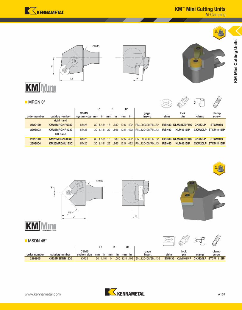
KM
Min
i Cut
ting
Uni
ts
A137www.kennametal.com
KM™ Mini Cutting Units
L1 F H1
order number catalog numberCSMS
system size mm in mm in mm ingageinsert shim
lock pin clamp
clampscrew
right hand
2629139 KM25MRGNR0930 KM25 30 1.181 16 .630 12,5 .492 RN..090300/RN..32 IRSN33 KLM34LT9PKG CKM7LP STCM9T9
2398803 KM25MRGNR1230 KM25 30 1.181 22 .866 12,5 .492 RN..120400/RN..43 IRSN43 KLM4615IP CKM20LP STCM1115IP
left hand
2629140 KM25MRGNL0930 KM25 30 1.181 16 .630 12,5 .492 RN..090300/RN..32 IRSN33 KLM34LT9PKG CKM7LP STCM9T9
2398804 KM25MRGNL1230 KM25 30 1.181 22 .866 12,5 .492 RN..120400/RN..43 IRSN43 KLM4615IP CKM20LP STCM1115IP
� MRGN 0°
L1 F H1
order number catalog numberCSMS
system size mm in mm in mm ingageinsert shim
lock pin clamp
clampscrew
2398805 KM25MSDNN1230 KM25 30 1.181 0 .000 12,5 .492 SN..120408/SN..432 ISSN433 KLM4615IP CKM20LP STCM1115IP
� MSDN 45°
M-Clamping
KEN_TOOLINGSYSTEMS11_A136_A137.qxp:WIDIA 2:09 PM Page A137

KM
Min
i C
utt
ing
Un
its
A138 www.kennametal.com
KM™ Mini Cutting Units
L1 F H1
order number catalog numberCSMS
system size mm in mm in mm ingageinsert shim
lock pin clamp
clampscrew
right hand
2398806 KM25MSKNR1230 KM25 30 1.181 22 .866 12,5 .492 SN..120408/SN..432 ISSN433 KLM4615IP CKM20LP STCM1115IP
left hand
2398807 KM25MSKNL1230 KM25 30 1.181 22 .866 12,5 .492 SN..120408/SN..432 ISSN433 KLM4615IP CKM20LP STCM1115IP
� MSKN 75°
L1 F H1
order number catalog numberCSMS
system size mm in mm in mm ingageinsert shim
lock pin clamp
clampscrew
right hand
2398808 KM25MSRNR1230 KM25 30 1.181 13 .512 12,5 .492 SN..120408/SN..432 ISSN433 KLM4615IP CKM20LP STCM1115IP
left hand
2398809 KM25MSRNL1230 KM25 30 1.181 13 .512 12,5 .492 SN..120408/SN..432 ISSN433 KLM4615IP CKM20LP STCM1115IP
� MSRN 75°
M-Clamping
KEN_TOOLINGSYSTEMS11_A138_A139.qxp:WIDIA 9:41 AM Page A138

L1 F H1
order number catalog numberCSMS
system size mm in mm in mm ingageinsert shim
lock pin clamp
clampscrew
right hand
2398810 KM25MSSNR1230 KM25 30,0 1.181 7,35 .289 12,5 .492 SN..120408/SN..432 ISSN433 KLM4615IP CKM20LP STCM1115IP
left hand
2398811 KM25MSSNL1230 KM25 30,0 1.181 7,35 .289 12,5 .492 SN..120408/SN..432 ISSN433 KLM4615IP CKM20LP STCM1115IP
KM
Min
i C
utt
ing
Un
its
A139www.kennametal.com
KM™ Mini Cutting Units
� MSSN 45°
L1 F H1
order number catalog numberCSMS
system size mm in mm in mm ingageinsert shim
lock pin clamp
clampscrew
right hand
2655560 KM25MTFNR1630 KM25 30 1.181 16 .630 12,5 .492 TN..160408/TN..332 ITSN323 KLM34L9IP CKM20LP STCM119IP
2398812 KM25MTFNR2230 KM25 30 1.181 16 .630 12,5 .492 TN..220408/TN..432 ITSN433 KLM4615IP CKM20LP STCM1115IP
left hand
2655561 KM25MTFNL1630 KM25 30 1.181 16 .630 12,5 .492 TN..160408/TN..332 ITSN323 KLM34L9IP CKM20LP STCM119IP
2398813 KM25MTFNL2230 KM25 30 1.181 16 .630 12,5 .492 TN..220408/TN..432 ITSN433 KLM4615IP CKM20LP STCM1115IP
� MTFN 90°
M-Clamping
KEN_TOOLINGSYSTEMS11_A138_A139.qxp:WIDIA 9:42 AM Page A139

L1 F H1
order number catalog numberCSMS
system size mm in mm in mm ingageinsert shim
lockpin clamp
clampscrew
right hand
2655594 KM25MTJNR1630 KM25 30 1.181 16 .630 12,5 .492 TN..160408/TN..332 ITSN323 KLM34L9IP CKM20LP STCM119IP
2398816 KM25MTJNR2230 KM25 30 1.181 16 .630 12,5 .492 TN..220408/TN..432 ITSN433 KLM4615IP CKM20LP STCM1115IP
left hand
2655595 KM25MTJNL1630 KM25 30 1.181 16 .630 12,5 .492 TN..160408/TN..332 ITSN323 KLM34L9IP CKM20LP STCM119IP
2398817 KM25MTJNL2230 KM25 30 1.181 16 .630 12,5 .492 TN..220408/TN..432 ITSN433 KLM4615IP CKM20LP STCM1115IP
L1 F H1
order number catalog numberCSMS
system size mm in mm in mm ingageinsert shim
lock pin clamp
clampscrew
right hand
3487542 KM20MTGNR1625 KM20 25 .984 12,5 .492 9,5 .375 TN..160408/TN..332 ITSN322 KLM34L CKM7LP STCM9
2655562 KM25MTGNR1630 KM25 30 1.181 16,0 .630 12,5 .492 TN..160408/TN..332 ITSN323 KLM34L9IP CKM20LP STCM119IP
2398814 KM25MTGNR2230 KM25 30 1.181 16,0 .630 12,5 .492 TN..220408/TN..432 ITSN433 KLM4615IP CKM20LP STCM1115IP
left hand
3487541 KM20MTGNL1625 KM20 25 .984 12,5 .492 9,5 .375 TN..160408/TN..332 ITSN322 KLM34L CKM7LP STCM9
2655593 KM25MTGNL1630 KM25 30 1.181 16,0 .630 12,5 .492 TN..160408/TN..332 ITSN323 KLM34L9IP CKM20LP STCM119IP
2398815 KM25MTGNL2230 KM25 30 1.181 16,0 .630 12,5 .492 TN..220408/TN..432 ITSN433 KLM4615IP CKM20LP STCM1115IP
KM
Min
i C
utt
ing
Un
its
A140 www.kennametal.com
KM™ Mini Cutting Units
� MTGN 90°
� MTJN 93°
M-Clamping
KEN_TOOLINGSYSTEMS11_A140_A141.qxp:WIDIA 9:42 AM Page A140

KM
Min
i C
utt
ing
Un
its
A141www.kennametal.com
L1 F H1
order number catalog numberCSMS
system size mm in mm in mm ingageinsert shim
lock pin clamp
clampscrew
right hand
3487548 KM20MVJNR1630 KM20 30 1.18112,50 .492 9,5 .375 VN..160408/VN..332 IVSN322 KLM34L CKM7LP STCM9
2398818 KM25MVJNR1630 KM25 30 1.18116,00 .630 12,5 .492 VN..160408/VN..332 IVSN322 KLM34L9IP CKM20LP STCM119IP
left hand
3487547 KM20MVJNL1630 KM20 30 1.18112,50 .492 9,5 .375 VN..160408/VN..332 IVSN322 KLM34L CKM7LP STCM9
2398819 KM25MVJNL1630 KM25 30 1.18116,00 .630 12,5 .492 VN..160408/VN..332 IVSN322 KLM34L9IP CKM20LP STCM119IP
KM™ Mini Cutting Units
� MVJN 93°
L1 F H1
order number catalog numberCSMS
system size mm in mm in mm ingageinsert shim
lock pin clamp
clampscrew
right hand
2398820 KM25MVUNR1630 KM25 30 1.181 28,5 1.122 12,5 .492 VN..160408/VN..332 IVSN322 KLM34L9IP CKM20LP STCM119IP
left hand
2398821 KM25MVUNL1630 KM25 30 1.181 28,5 1.122 12,5 .492 VN..160408/VN..332 IVSN322 KLM34L9IP CKM20LP STCM119IP
� MVUN 93°
M-Clamping
KEN_TOOLINGSYSTEMS11_A140_A141.qxp:WIDIA 9:42 AM Page A141

L1 F H1
order number catalog numberCSMS
system size mm in mm in mm ingageinsert shim
lock pin clamp
clampscrew
right hand
3487544 KM20MWLNR0625 KM20 25 .984 12,5 .492 9,5 .375 WN..060408/WN..332 IWSN322 KLM34L CKM7LP STCM9
3487550 KM20MWLNR0825 KM20 25 .984 12,5 .492 9,5 .375 WN..080408/WN..432 IWSN433 KLM46 CKM7LP STCM9
2398823 KM25MWLNR0830 KM25 30 1.181 22,0 .866 12,5 .492 WN..080408/WN..432 IWSN433 KLM4615IP CKM20LP STCM1115IP
left hand
3487543 KM20MWLNL0625 KM20 25 .984 12,5 .492 9,5 .375 WN..060408/WN..332 IWSN322 KLM34L CKM7LP STCM9
3487549 KM20MWLNL0825 KM20 25 .984 12,5 .492 9,5 .375 WN..080408/WN..432 IWSN433 KLM46 CKM7LP STCM9
2398824 KM25MWLNL0830 KM25 30 1.181 22,0 .866 12,5 .492 WN..080408/WN..432 IWSN433 KLM4615IP CKM20LP STCM1115IP
L1 F H1
order number catalog numberCSMS
system size mm in mm in mm ingageinsert shim
lock pin
2398822 KM25MVVNN1630 KM25 30 1.181 0 .000 12,5 .492 VN..160408/VN..332 IVSN322 KLM34L9IP
A142 www.kennametal.com
KM™ Mini Cutting Units
� MVVN 72° 30'
� MWLN 95°
M-Clamping
KM
Min
i C
utt
ing
Un
its
KEN_TOOLINGSYSTEMS11_A142_A143.qxp:WIDIA 9:42 AM Page A142

A143www.kennametal.com
KM™ Mini Cutting UnitsP-Clamping
L1 F H1
order number catalog number mm in mm in mm ingageinsert shim
leverscrew
shimpin
togglelever punch
right hand
3397169 KM20PCLNR1225 25,00 .984 12,5 .492 9,5 .375 CN..120408/CN..432 512.112 514.123 513.023 511.023 515.018
left hand
3397168 KM20PCLNL1225 25,00 .984 12,5 .492 9,5 .375 CN..120408/CN..432 512.112 514.123 513.023 511.023 515.018
L1 F H1
order number catalog number mm in mm in mm ingageinsert shim
lever screw
shimpin
togglelever punch
right hand
3397171 KM20PCKNR1225 25 .984 12,5 .492 9,5 .375 CN..120408/CN..432 512.112 514.123 513.023 511.023 515.018
left hand
3397170 KM20PCKNL1225 25 .984 12,5 .492 9,5 .375 CN..120408/CN..432 512.112 514.123 513.023 511.023 515.018
� PCKN 75°
� PCLN 95°
KM
Min
i C
utt
ing
Un
its
95˚
KEN_TOOLINGSYSTEMS11_A142_A143.qxp:WIDIA 9:42 AM Page A143

KM
Min
i Cut
ting
Uni
ts
A144 www.kennametal.com
KM™ Mini Cutting UnitsP-Clamping
L1 F H1
order number catalog number mm in mm in mm ingageinsert shim
lever screw
shimpin
togglelever punch
right hand3397213 KM20PDJNR1125 25 .984 12,5 .492 9,5 .375 DN..110408/DN..332 512.060 514.118 513.060 511.060 515.018
left hand3397172 KM20PDJNL1125 25 .984 12,5 .492 9,5 .375 DN..110408/DN..332 512.060 514.118 513.060 511.060 515.018
� PDJN 93°
� PWLN 95°
L1 F H1
order number catalog number mm in mm in mm ingageinsert shim
lever screw
shimpin
togglelever punch
right hand3397215 KM20PWLNR0625 25 .984 17,0 .669 9,5 .375 WN..060408/WN..332 512.134 514.118 513.018 511.018 515.018
left hand3397214 KM20PWLNL0625 25 .984 17,0 .669 9,5 .375 WN..060408/WN..332 512.134 514.118 513.018 511.018 515.018
KEN_TOOLINGSYSTEMS11_A144_A145.qxp:WIDIA 2:04 PM Page A144

L1 F H1
order number catalog numberCSMS
system size mm in mm in mm ingageinsert shim
insert screw
shim screw
right hand
3487553 KM20SCACR0925 KM20 25 .984 12,5 .492 9,5 .375 CC..09T308/CC..3252 SKCP343 MS1156 SRS3
left hand
3487512 KM20SCACL0925 KM20 25 .984 12,5 .492 9,5 .375 CC..09T308/CC..3252 SKCP343 MS1156 SRS3
KM
Min
i C
utt
ing
Un
its
A145www.kennametal.com
KM™ Mini Cutting Units
� SCAC 90°
L1 F H1
order number catalog numberCSMS
system size mm in mm in mm ingageinsert shim
insert screw
shim screw
right hand
3487555 KM20SCLCR0925 KM20 25 .984 12,5 .492 9,5 .375 CC..09T308/CC..3252 SKCP343 MS1156 SRS3
3487557 KM20SCLCR1225 KM20 25 .984 12,5 .492 9,5 .375 CC..120408/CC..432 SKCP453 MS1158 SRS4
2399472 KM25SCLCR0930 KM25 30 1.181 16,0 .630 12,5 .492 CC..09T308/CC..3252 SKCP343 MS1156 SRS3
2399474 KM25SCLCR1230 KM25 30 1.181 16,0 .630 12,5 .492 CC..120408/CC..432 SKCP453 MS1158 SRS4
left hand
3487554 KM20SCLCL0925 KM20 25 .984 12,5 .492 9,5 .375 CC..09T308/CC..3252 SKCP343 MS1156 SRS3
3487556 KM20SCLCL1225 KM20 25 .984 12,5 .492 9,5 .375 CC..120408/CC..432 SKCP453 MS1158 SRS4
2399473 KM25SCLCL0930 KM25 30 1.181 16,0 .630 12,5 .492 CC..09T308/CC..3252 SKCP343 MS1156 SRS3
2399475 KM25SCLCL1230 KM25 30 1.181 16,0 .630 12,5 .492 CC..120408/CC..432 SKCP453 MS1158 SRS4
� SCLC 95°
S-Clamping
KEN_TOOLINGSYSTEMS11_A144_A145.qxp:WIDIA 9:43 AM Page A145

L1 F H1
order number catalog numberCSMS
system size mm in mm in mm ingageinsert shim
insert screw
shim screw
right hand
3487495 KM20SDJCR1125 KM20 25 .984 12,5 .492 9,5 .375 DC..11T308/DC..3252 SKDP343 MS1156 SRS3
3487497 KM20SDJCR1525 KM20 25 .984 12,5 .492 9,5 .375 DC..150408/DC..432 .SKDP453 MS1158 SRS4
2399476 KM25SDJCR1130 KM25 30 1.181 16,0 .630 12,5 .492 DC..11T308/DC..3252 SKDP343 MS1156 SRS3
left hand
3487494 KM20SDJCL1125 KM20 25 .984 12,5 .492 9,5 .375 DC..11T308/DC..3252 SKDP343 MS1156 SRS3
3487496 KM20SDJCL1525 KM20 25 .984 12,5 .492 9,5 .375 DC..150408/DC..432 SKDP453 MS1158 SRS4
2399477 KM25SDJCL1130 KM25 30 1.181 16,0 .630 12,5 .492 DC..11T308/DC..3252 SKDP343 MS1156 SRS3
KM
Min
i C
utt
ing
Un
its
A146 www.kennametal.com
� SDJC 93°
L1 F H1
order number catalog numberCSMS
system size mm in mm in mm ingageinsert shim
insert screw
shim screw
3487508 KM20SDPCN1530 KM20 30 1.181 0 .000 9,5 .375 DC..150408/DC..432 SKDP453 MS1158 SRS4
2399478 KM25SDPCN1130 KM25 30 1.181 0 .000 12,5 .492 DC..11T308/DC..3252 SKDP343 MS1156 SRS3
� SDPC 62° 30'
KM™ Mini Cutting UnitsS-Clamping
KEN_TOOLINGSYSTEMS11_A146_A147.qxp:WIDIA 9:43 AM Page A146
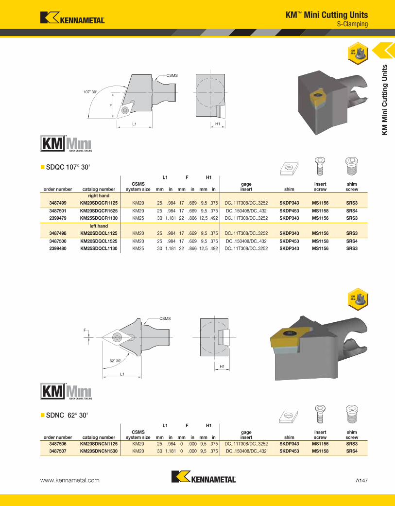
KM
Min
i C
utt
ing
Un
its
A147www.kennametal.com
L1 F H1
order number catalog numberCSMS
system size mm in mm in mm ingageinsert shim
insert screw
shim screw
right hand
3487499 KM20SDQCR1125 KM20 25 .984 17 .669 9,5 .375 DC..11T308/DC..3252 SKDP343 MS1156 SRS3
3487501 KM20SDQCR1525 KM20 25 .984 17 .669 9,5 .375 DC..150408/DC..432 SKDP453 MS1158 SRS4
2399479 KM25SDQCR1130 KM25 30 1.181 22 .866 12,5 .492 DC..11T308/DC..3252 SKDP343 MS1156 SRS3
left hand
3487498 KM20SDQCL1125 KM20 25 .984 17 .669 9,5 .375 DC..11T308/DC..3252 SKDP343 MS1156 SRS3
3487500 KM20SDQCL1525 KM20 25 .984 17 .669 9,5 .375 DC..150408/DC..432 SKDP453 MS1158 SRS4
2399480 KM25SDQCL1130 KM25 30 1.181 22 .866 12,5 .492 DC..11T308/DC..3252 SKDP343 MS1156 SRS3
KM™ Mini Cutting Units
� SDQC 107° 30'
L1 F H1
order number catalog numberCSMS
system size mm in mm in mm ingageinsert shim
insert screw
shim screw
3487506 KM20SDNCN1125 KM20 25 .984 0 .000 9,5 .375 DC..11T308/DC..3252 SKDP343 MS1156 SRS3
3487507 KM20SDNCN1530 KM20 30 1.181 0 .000 9,5 .375 DC..150408/DC..432 SKDP453 MS1158 SRS4
� SDNC 62° 30'
S-Clamping
KEN_TOOLINGSYSTEMS11_A146_A147.qxp:WIDIA 9:43 AM Page A147

L1 F H1
order number catalog numberCSMS
system size mm in mm in mm ingageinsert shim
insert screw
shim screw
right hand
2399481 KM25SDUCR1130 KM25 30 1.181 22 .866 12,5 .492 DC..11T308/DC..3252 SKDP343 MS1156 SRS3
left hand
2399482 KM25SDUCL1130 KM25 30 1.181 22 .866 12,5 .492 DC..11T308/DC..3252 SKDP343 MS1156 SRS3
KM
Min
i C
utt
ing
Un
its
A148 www.kennametal.com
KM™ Mini Cutting Units
� SDUC 93°
S-Clamping
KEN_TOOLINGSYSTEMS11_A148_A149.qxp:WIDIA 9:43 AM Page A148

mm in mm in mm in
L1 F H1
order number catalog numberCSMS
system sizegageinsert
insert screw
2399483 KM25SRDCN0830 KM25 30 1.181 4 .158 12,5 .492 RC..0803M0 MS1154
KM
Min
i C
utt
ing
Un
its
A149www.kennametal.com
KM™ Mini Cutting Units
� SRDC 0°
L1 F H1
order number catalog numberCSMS
system size mm in mm in mm ingageinsert shim
insert screw
shim screw
right hand
2399484 KM25SRGCR1030 KM25 30 1.181 22 .866 12,5 .492 RC..10T3M0 SKRN100300 MS1156 SRS3
left hand
2399485 KM25SRGCL1030 KM25 30 1.181 22 .866 12,5 .492 RC..10T3M0 SKRN100300 MS1156 SRS3
� SRGC 90°
S-Clamping
KEN_TOOLINGSYSTEMS11_A148_A149.qxp:WIDIA 9:43 AM Page A149

L1 F H1
order number catalog numberCSMS
system size mm in mm in mm ingageinsert shim
insert screw
shim screw
2399486 KM25SSDCN1230 KM25 30 1.181 0 .000 12,5 .492 SC..120408/SC..432 SKSP453 MS1158 SRS4
KM
Min
i C
utt
ing
Un
its
A150 www.kennametal.com
KM™ Mini Cutting Units
� SSDC 45°
L1 F H1
order number catalog numberCSMS
system size mm in mm in mm ingageinsert shim
insert screw
shim screw
right hand
2399487 KM25STFCR1630 KM25 30 1.181 16 .630 12,5 .492 TC..16T308/TC..3252 SKTP343 MS1156 SRS3
left hand
2399488 KM25STFCL1630 KM25 30 1.181 16 .630 12,5 .492 TC..16T308/TC..3252 SKTP343 MS1156 SRS3
� STFC 90°
S-Clamping
KEN_TOOLINGSYSTEMS11_A150_A151.qxp:WIDIA 9:44 AM Page A150
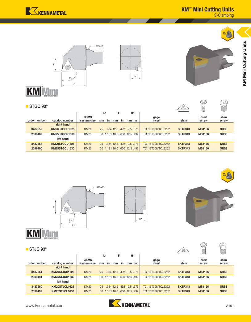
L1 F H1
order number catalog numberCSMS
system size mm in mm in mm ingageinsert shim
insert screw
shim screw
right hand
3487561 KM20STJCR1625 KM20 25 .984 12,5 .492 9,5 .375 TC..16T308/TC..3252 SKTP343 MS1156 SRS3
2399491 KM25STJCR1630 KM25 30 1.181 16,0 .630 12,5 .492 TC..16T308/TC..3252 SKTP343 MS1156 SRS3
left hand
3487560 KM20STJCL1625 KM20 25 .984 12,5 .492 9,5 .375 TC..16T308/TC..3252 SKTP343 MS1156 SRS3
2399492 KM25STJCL1630 KM25 30 1.181 16,0 .630 12,5 .492 TC..16T308/TC..3252 SKTP343 MS1156 SRS3
L1 F H1
order number catalog numberCSMS
system size mm in mm in mm ingageinsert shim
insert screw
shim screw
right hand
3487559 KM20STGCR1625 KM20 25 .984 12,5 .492 9,5 .375 TC..16T308/TC..3252 SKTP343 MS1156 SRS3
2399489 KM25STGCR1630 KM25 30 1.181 16,0 .630 12,5 .492 TC..16T308/TC..3252 SKTP343 MS1156 SRS3
left hand
3487558 KM20STGCL1625 KM20 25 .984 12,5 .492 9,5 .375 TC..16T308/TC..3252 SKTP343 MS1156 SRS3
2399490 KM25STGCL1630 KM25 30 1.181 16,0 .630 12,5 .492 TC..16T308/TC..3252 SKTP343 MS1156 SRS3
KM
Min
i C
utt
ing
Un
its
A151www.kennametal.com
KM™ Mini Cutting Units
� STGC 90°
� STJC 93°
S-Clamping
KEN_TOOLINGSYSTEMS11_A150_A151.qxp:WIDIA 9:44 AM Page A151

L1 F H1
order number catalog numberCSMS
system size mm in mm in mm ingageinsert shim
insert screw
shim screw
right hand
3487563 KM20SVABR1630 KM20 30 1.181 12,5 .492 9,5 .375 VB..160408/VB..332 SKVN343 MS1156 SRS3
left hand
3487562 KM20SVABL1630 KM20 30 1.181 12,5 .492 9,5 .375 VB..160408/VB..332 SKVN343 MS1156 SRS3
KM
Min
i C
utt
ing
Un
its
A152 www.kennametal.com
KM™ Mini Cutting Units
� SVAB 90°
L1 F H1
order number catalog numberCSMS
system size mm in mm in mm ingageinsert shim
insert screw
shim screw
right hand
3487565 KM20SVJBR1125 KM20 25 .984 12,5 .492 9,5 .375 VB..110304/VB..221 — MS1153 —
3487567 KM20SVJBR1630 KM20 30 1.181 12,5 .492 9,5 .375 VB..160408/VB..332 SKVN343 MS1156 SRS3
3397261 KM25SVJBL1130 KM25 30 1.181 16,0 .630 12,5 .492 VB..110304/VB..221 — MS1153 —
3397262 KM25SVJBR1130 KM25 30 1.181 16,0 .630 12,5 .492 VB..110304/VB..221 — MS1153 —
3365589 KM25SVJBR1630 KM25 30 1.181 16,0 .630 12,5 .492 VB..160408/VB..332 SKVN343 MS1156 SRS3
left hand
3487564 KM20SVJBL1125 KM20 25 .984 12,5 .492 9,5 .375 VB..110304/VB..221 — MS1153 —
3487566 KM20SVJBL1630 KM20 30 1.181 12,5 .492 9,5 .375 VB..160408/VB..332 SKVN343 MS1156 SRS3
3365590 KM25SVJBL1630 KM25 30 1.181 16,0 .630 12,5 .492 VB..160408/VB..332 SKVN343 MS1156 SRS3
� SVJB 93°
S-Clamping
KEN_TOOLINGSYSTEMS11_A152_A153.qxp:WIDIA 9:44 AM Page A152
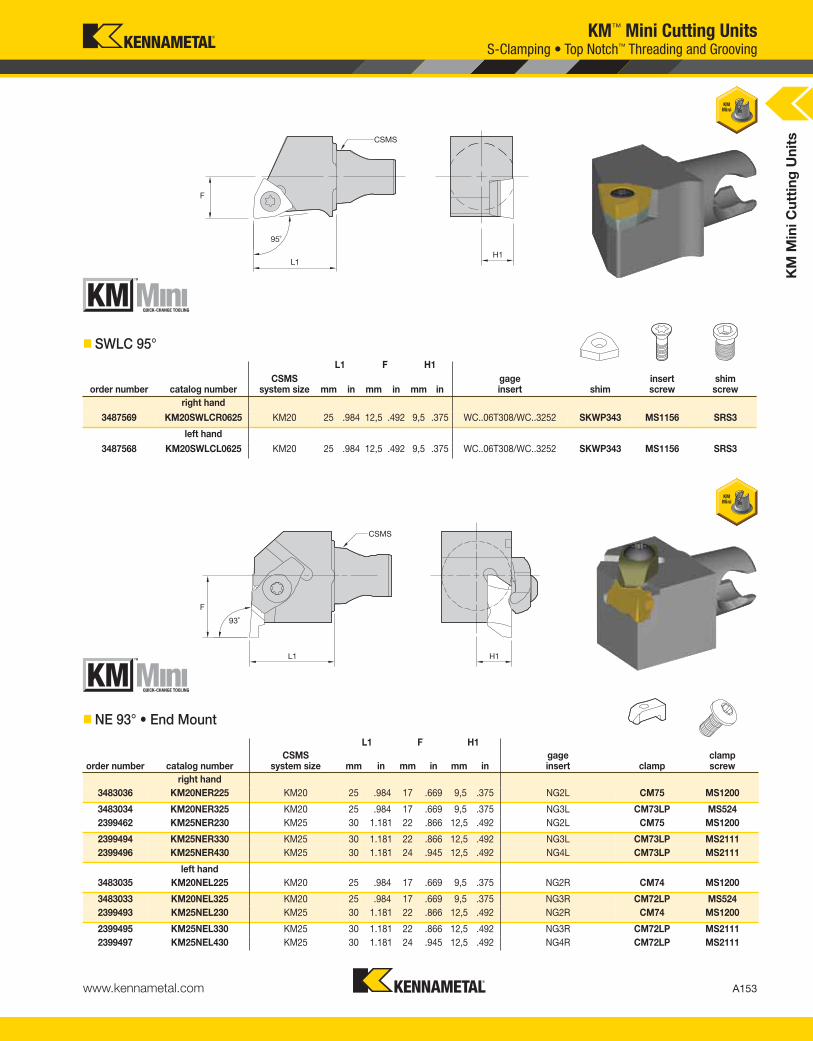
L1 F H1
order number catalog numberCSMS
system size mm in mm in mm ingageinsert clamp
clampscrew
right hand
3483036 KM20NER225 KM20 25 .984 17 .669 9,5 .375 NG2L CM75 MS1200
3483034 KM20NER325 KM20 25 .984 17 .669 9,5 .375 NG3L CM73LP MS524
2399462 KM25NER230 KM25 30 1.181 22 .866 12,5 .492 NG2L CM75 MS1200
2399494 KM25NER330 KM25 30 1.181 22 .866 12,5 .492 NG3L CM73LP MS2111
2399496 KM25NER430 KM25 30 1.181 24 .945 12,5 .492 NG4L CM73LP MS2111
left hand
3483035 KM20NEL225 KM20 25 .984 17 .669 9,5 .375 NG2R CM74 MS1200
3483033 KM20NEL325 KM20 25 .984 17 .669 9,5 .375 NG3R CM72LP MS524
2399493 KM25NEL230 KM25 30 1.181 22 .866 12,5 .492 NG2R CM74 MS1200
2399495 KM25NEL330 KM25 30 1.181 22 .866 12,5 .492 NG3R CM72LP MS2111
2399497 KM25NEL430 KM25 30 1.181 24 .945 12,5 .492 NG4R CM72LP MS2111
KM
Min
i C
utt
ing
Un
its
A153www.kennametal.com
KM™ Mini Cutting Units
L1 F H1
order number catalog numberCSMS
system size mm in mm in mm ingageinsert shim
insert screw
shim screw
right hand
3487569 KM20SWLCR0625 KM20 25 .984 12,5 .492 9,5 .375 WC..06T308/WC..3252 SKWP343 MS1156 SRS3
left hand
3487568 KM20SWLCL0625 KM20 25 .984 12,5 .492 9,5 .375 WC..06T308/WC..3252 SKWP343 MS1156 SRS3
� SWLC 95°
� NE 93° • End Mount
S-Clamping • Top Notch™ Threading and Grooving
KEN_TOOLINGSYSTEMS11_A152_A153.qxp:WIDIA 9:44 AM Page A153

L1 F H1
order number catalog numberCSMS
system size mm in mm in mm ingageinsert clamp
clampscrew
right hand
3483030 KM20NSR230 KM20 30 1.181 12,5 .492 9,5 .375 NG2R CM74 MS1200
3483028 KM20NSR330 KM20 30 1.181 12,5 .492 9,5 .375 NG3R CM72LP MS524
2399498 KM25NSR230 KM25 30 1.181 16,0 .630 12,5 .492 NG2R CM74 MS1200
2399500 KM25NSR330 KM25 30 1.181 16,0 .630 12,5 .492 NG3R CM72LP MS2111
2399502 KM25NSR430 KM25 30 1.181 16,0 .630 12,5 .492 NG4R CM212LP MS2111
left hand
3483029 KM20NSL230 KM20 30 1.181 12,5 .492 9,5 .375 NG2L CM75 MS1200
3483027 KM20NSL330 KM20 30 1.181 12,5 .492 9,5 .375 NG3L CM73LP MS524
2399499 KM25NSL230 KM25 30 1.181 16,0 .630 12,5 .492 NG2L CM75 MS1200
2399501 KM25NSL330 KM25 30 1.181 16,0 .630 12,5 .492 NG3L CM73LP MS2111
2399503 KM25NSL430 KM25 30 1.181 16,0 .630 12,5 .492 NG4L CM213LP MS2111
KM
Min
i C
utt
ing
Un
its
A154 www.kennametal.com
KM™ Mini Cutting UnitsTop Notch™ Threading and Grooving
� NS 93° • Side Mount
KEN_TOOLINGSYSTEMS11_A154_A155.qxp:WIDIA 9:44 AM Page A154

KM
Min
i C
utt
ing
Un
its
A155www.kennametal.com
L1 F H1
order number catalog numberCSMS
system size mm in mm in mm ingageinsert shim
insert screw
shim screw
clamp assembly
right hand
3482966 KM20LSER1625 KM20 25 .984 17 .669 9,5 .375 LT16EL SMYI3 SSA3T SSY3T CKC3
2399506 KM25LSER1630 KM25 30 1.181 22 .866 12,5 .492 LT16EL SMYI3 SSA3T SSY3T CKC3
left hand
3482965 KM20LSEL1625 KM20 25 .984 17 .669 9,5 .375 LT16ER SMYE3 SSA3T SSY3T CKC3
2399507 KM25LSEL1630 KM25 30 1.181 22 .866 12,5 .492 LT16ER SMYE3 SSA3T SSY3T CKC3
NOTE: Cutting units are supplied with insert screw and clamp assembly. However, tools are designed to use either the insert screw or the clamp assembly, not both.
� LSE 90°
KM™ Mini Cutting UnitsLT Threading
� LSS 90°
NOTE: Cutting units are supplied with insert screw and clamp assembly. However, tools are designed to use either the insert screw or the clamp assembly, not both.
L1 F H1
order number catalog numberCSMS
system size mm in mm in mm ingageinsert shim
insert screw
shim screw
clamp assembly
right hand
3482968 KM20LSSR1625 KM20 25 .984 12,5 .492 9,5 .375 LT16ER SMYE3 SSA3T SSY3T CKC3
2399504 KM25LSSR1630 KM25 30 1.181 16,0 .630 12,5 .492 LT16ER SMYE3 SSA3T SSY3T CKC3
3176219 KM25LSSR2230 KM25 30 1.181 16,0 .630 12,5 .492 LT22ER SMYE4 SSA4T SSY4T CKC4
left hand
3482967 KM20LSSL1625 KM20 25 .984 12,5 .492 9,5 .375 LT16EL SMYI3 SSA3T SSY3T CKC3
2399505 KM25LSSL1630 KM25 30 1.181 16,0 .630 12,5 .492 LT16EL SMYI3 SSA3T SSY3T CKC3
3176220 KM25LSSL2230 KM25 30 1.181 16,0 .630 12,5 .492 LT22EL SMYI4 SSA4T SSY4T CKC4
KEN_TOOLINGSYSTEMS11_A154_A155.qxp:WIDIA 9:45 AM Page A155

L1 FS W min H1 CD
order number catalog numberCSMS
system sizeseatsize mm in mm in mm in mm in mm in
right hand
3482929 KM20A4SMR011330 KM20 1.5 30 1.181 11,8 .463 1,5 .059 9,5 .375 13,5 .53
3482931 KM20A4SMR021430 KM20 2 30 1.181 11,5 .453 2,0 .079 9,5 .375 14,0 .55
3482935 KM20A4SMR031430 KM20 3 30 1.181 11,0 .433 3,0 .118 9,5 .375 14,0 .55
3482937 KM20A4SMR041430 KM20 4 30 1.181 10,5 .413 4,0 .157 9,5 .375 14,0 .55
3482933 KM20A4SMR2B1430 KM20 2B 30 1.181 11,3 .443 2,5 .098 9,5 .375 14,0 .55
3377363 KM25A4SMR011330 KM25 1 30 1.181 15,3 .600 1,5 .059 12,5 .492 13,5 .53
3377291 KM25A4SMR021430 KM25 2 30 1.181 15,0 .591 2,0 .079 12,5 .492 14,0 .55
2399464 KM25A4SMR031430 KM25 3 30 1.181 14,5 .571 3,0 .118 12,5 .492 14,0 .55
2399466 KM25A4SMR041430 KM25 4 30 1.181 14,0 .551 4,0 .157 12,5 .492 14,0 .55
2399468 KM25A4SMR051935 KM25 5 35 1.378 13,5 .531 5,0 .197 12,5 .492 19,0 .75
3377289 KM25A4SMR2B1430 KM25 2B 30 1.181 14,8 .581 2,5 .098 12,5 .492 14,0 .55
left hand
3482928 KM20A4SML011330 KM20 1.5 30 1.181 11,8 .463 1,5 .059 9,5 .375 13,5 .53
3482930 KM20A4SML021430 KM20 2 30 1.181 11,5 .453 2,0 .079 9,5 .375 14,0 .55
3482934 KM20A4SML031430 KM20 3 30 1.181 11,0 .433 3,0 .118 9,5 .375 14,0 .55
3482936 KM20A4SML041430 KM20 4 30 1.181 10,5 .413 4,0 .157 9,5 .375 14,0 .55
3482932 KM20A4SML2B1430 KM20 2B 30 1.181 11,3 .443 2,5 .098 9,5 .375 14,0 .55
3377292 KM25A4SML011330 KM25 1 30 1.181 15,3 .600 1,5 .059 12,5 .492 13,5 .53
3377290 KM25A4SML021430 KM25 2 30 1.181 15,0 .591 2,0 .079 12,5 .492 14,0 .55
2399465 KM25A4SML031430 KM25 3 30 1.181 14,5 .571 3,0 .118 12,5 .492 14,0 .55
2399467 KM25A4SML041430 KM25 4 30 1.181 14,0 .551 4,0 .157 12,5 .492 14,0 .55
2399469 KM25A4SML051935 KM25 5 35 1.378 13,5 .531 5,0 .197 12,5 .492 19,0 .75
3377288 KM25A4SML2B1430 KM25 2B 30 1.181 14,8 .581 2,5 .098 12,5 .492 14,0 .55
KM
Min
i C
utt
ing
Un
its
A156 www.kennametal.com
KM™ Mini Cutting UnitsA4™ Grooving
� A4SM • Side Mount
(continued)
KEN_TOOLINGSYSTEMS11_A156_A157.qxp:WIDIA 9:45 AM Page A156

KM
Min
i C
utt
ing
Un
its
A157www.kennametal.com
� Spare Parts
NOTE: W min supplied for reference only. See the Kennametal Innovations Master Catalog Cutting Tools 2013 for actual insert width. Always match seat size of insert to seat size of holder.Seat size 2B cutting units only accepts 2B inserts.Seat size 2 cutting units accepts 2 or 2B inserts.
catalog numberclampscrew
clampscrew
right hand
KM20A4SMR011330 MS1156 —
KM20A4SMR021430 MS1160 —
KM20A4SMR031430 MS1160 —
KM20A4SMR041430 MS1160 —
KM20A4SMR2B1430 MS1160 —
KM25A4SMR011330 MS1156 —
KM25A4SMR021430 MS1160 —
KM25A4SMR031430 — MS2091
KM25A4SMR041430 — MS2091
KM25A4SMR051935 — MS2091
KM25A4SMR2B1430 MS1160 —
left hand
KM20A4SML011330 MS1156 —
KM20A4SML021430 MS1160 —
KM20A4SML031430 MS1160 —
KM20A4SML041430 MS1160 —
KM20A4SML2B1430 MS1160 —
KM25A4SML011330 MS1156 —
KM25A4SML021430 MS1160 —
KM25A4SML031430 — MS2091
KM25A4SML041430 — MS2091
KM25A4SML051935 — MS2091
KM25A4SML2B1430 MS1160 —
KM™ Mini Cutting UnitsA4™ Grooving
(A4SM • Side Mount continued)
KEN_TOOLINGSYSTEMS11_A156_A157.qxp:WIDIA 9:45 AM Page A157

catalog numberclampscrew
KM25A4ENN040730 MS2091
KM25A4ENN050930 MS2091
KM
Min
i C
utt
ing
Un
its
A158 www.kennametal.com
KM™ Mini Cutting UnitsA4™ Grooving
� A4EN • End Mount
� Spare Parts
NOTE: A4EN-style cutting units are designed without steel support for face grooving capacity. Cutting feed recommendations should be reduced by 25–30%.W min supplied for reference only. See the Kennametal Innovations Master Catalog Cutting Tools 2013 for actual insert width. Always match seat size of insert to seat size of holder.
L1S F W min H1 CD
order number catalog numberCSMS
system sizeseatsize mm in mm in mm in mm in mm in
2399470 KM25A4ENN040730 KM25 4 28 1.102 23 .906 4,0 .157 12,5 .492 7 .276
2399471 KM25A4ENN050930 KM25 5 28 1.083 25 .996 5,0 .197 12,5 .492 9 .354
A4EN Insert Mounting
Seating
Screw
Left Hand Right Hand
A4EN-style cutting units
can be used for either left-
or right-hand applications.
KEN_TOOLINGSYSTEMS11_A158_A159.qxp:WIDIA 9:45 AM Page A158
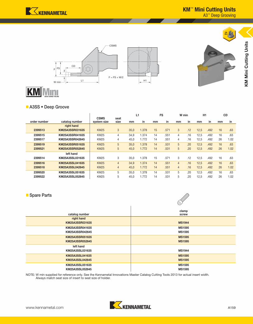
KM
Min
i C
utt
ing
Un
its
A159www.kennametal.com
catalog numberclampscrew
right hand
KM25A3SSR031635 MS1944
KM25A3SSR041635 MS1595
KM25A3SSR042645 MS1595
KM25A3SSR051635 MS1595
KM25A3SSR052645 MS1595
left hand
KM25A3SSL031635 MS1944
KM25A3SSL041635 MS1595
KM25A3SSL042645 MS1595
KM25A3SSL051635 MS1595
KM25A3SSL052645 MS1595
L1 FS W min H1 CD
order number catalog numberCSMS
system sizeseatsize mm in mm in mm in mm in mm in
right hand
2399513 KM25A3SSR031635 KM25 3 35,0 1.378 15 .571 3 .12 12,5 .492 16 .63
2399515 KM25A3SSR041635 KM25 4 34,9 1.374 14 .551 4 .16 12,5 .492 16 .63
2399517 KM25A3SSR042645 KM25 4 45,0 1.772 14 .551 4 .16 12,5 .492 26 1.02
2399519 KM25A3SSR051635 KM25 5 35,0 1.378 14 .531 5 .20 12,5 .492 16 .63
2399521 KM25A3SSR052645 KM25 5 45,0 1.772 14 .531 5 .20 12,5 .492 26 1.02
left hand
2399514 KM25A3SSL031635 KM25 3 35,0 1.378 15 .571 3 .12 12,5 .492 16 .63
2399516 KM25A3SSL041635 KM25 4 34,9 1.374 14 .551 4 .16 12,5 .492 16 .63
2399518 KM25A3SSL042645 KM25 4 45,0 1.772 14 .551 4 .16 12,5 .492 26 1.02
2399520 KM25A3SSL051635 KM25 5 35,0 1.378 14 .531 5 .20 12,5 .492 16 .63
2399522 KM25A3SSL052645 KM25 5 45,0 1.772 14 .531 5 .20 12,5 .492 26 1.02
KM™ Mini Cutting UnitsA3™ Deep Grooving
� A3SS • Deep Groove
� Spare Parts
NOTE: W min supplied for reference only. See the Kennametal Innovations Master Catalog Cutting Tools 2013 for actual insert width. Always match seat size of insert to seat size of holder.
KEN_TOOLINGSYSTEMS11_A158_A159.qxp:WIDIA 9:45 AM Page A159
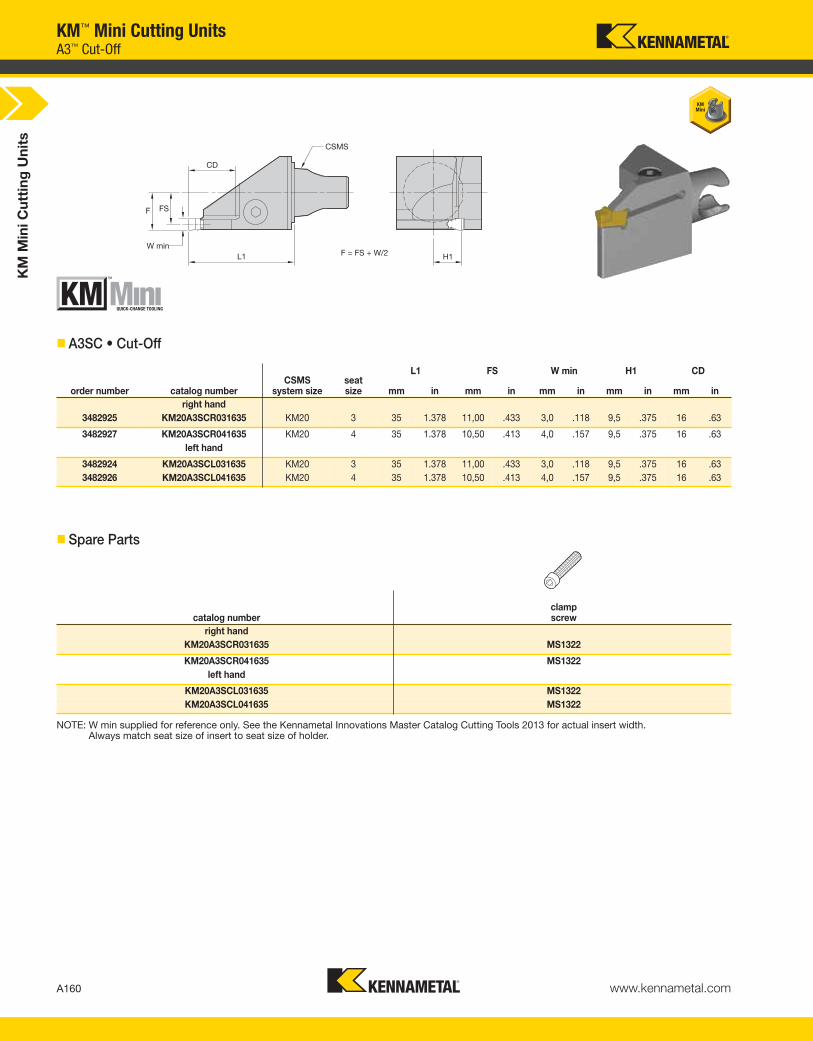
KM
Min
i C
utt
ing
Un
its
A160 www.kennametal.com
KM™ Mini Cutting UnitsA3™ Cut-Off
� A3SC • Cut-Off
� Spare Parts
NOTE: W min supplied for reference only. See the Kennametal Innovations Master Catalog Cutting Tools 2013 for actual insert width. Always match seat size of insert to seat size of holder.
order number catalog numberCSMS
system sizeseatsize mm in mm in mm in mm in mm in
right hand
3482925 KM20A3SCR031635 KM20 3 35 1.378 11,00 .433 3,0 .118 9,5 .375 16 .63
3482927 KM20A3SCR041635 KM20 4 35 1.378 10,50 .413 4,0 .157 9,5 .375 16 .63
left hand
3482924 KM20A3SCL031635 KM20 3 35 1.378 11,00 .433 3,0 .118 9,5 .375 16 .63
3482926 KM20A3SCL041635 KM20 4 35 1.378 10,50 .413 4,0 .157 9,5 .375 16 .63
catalog numberclampscrew
right hand
KM20A3SCR031635 MS1322
KM20A3SCR041635 MS1322
left hand
KM20A3SCL031635 MS1322
KM20A3SCL041635 MS1322
L1 FS W min H1 CD
KEN_TOOLINGSYSTEMS11_A160_A161.qxp:WIDIA 9:45 AM Page A160
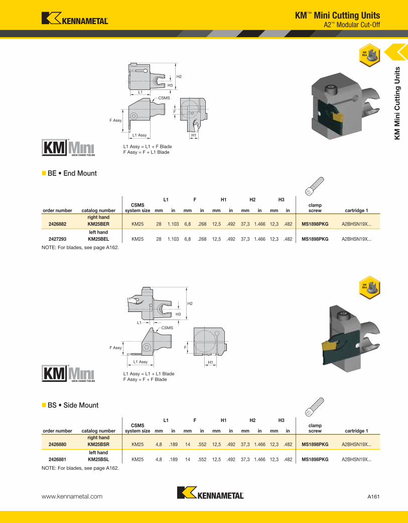
KM
Min
i C
utt
ing
Un
its
A161www.kennametal.com
KM™ Mini Cutting UnitsA2™ Modular Cut-Off
� BE • End Mount
NOTE: For blades, see page A162.
L1 F H1 H2 H3
order number catalog numberCSMS
system size mm in mm in mm in mm in mm inclampscrew cartridge 1
right hand
2426882 KM25BER KM25 28 1.103 6,8 .268 12,5 .492 37,3 1.466 12,3 .482 MS1898PKG A2BHSN19X...
left hand
2427293 KM25BEL KM25 28 1.103 6,8 .268 12,5 .492 37,3 1.466 12,3 .482 MS1898PKG A2BHSN19X...
L1 F H1 H2 H3
order number catalog numberCSMS
system size mm in mm in mm in mm in mm inclampscrew cartridge 1
right hand
2426880 KM25BSR KM25 4,8 .189 14 .552 12,5 .492 37,3 1.466 12,3 .482 MS1898PKG A2BHSN19X...
left hand
2426881 KM25BSL KM25 4,8 .189 14 .552 12,5 .492 37,3 1.466 12,3 .482 MS1898PKG A2BHSN19X...
� BS • Side Mount
NOTE: For blades, see page A162.
L1 Assy = L1 + F Blade
F Assy = F + L1 Blade
L1 Assy = L1 + L1 Blade
F Assy = F + F Blade
KEN_TOOLINGSYSTEMS11_A160_A161.qxp:WIDIA 9:45 AM Page A161
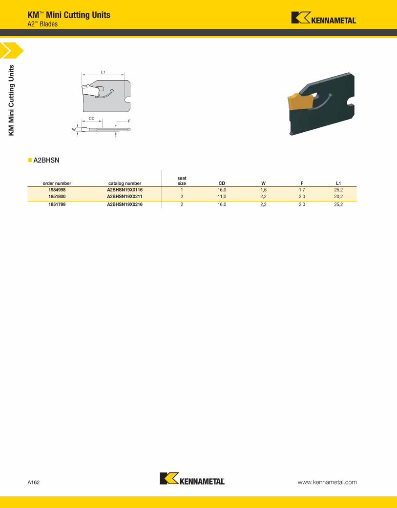
A162 www.kennametal.com
L1
CD
W
F
� A2BHSN
order number catalog numberseatsize CD W F L1
1984998 A2BHSN19X0116 1 16,0 1,6 1,7 25,2
1851800 A2BHSN19X0211 2 11,0 2,2 2,0 20,2
1851799 A2BHSN19X0216 2 16,0 2,2 2,0 25,2
KM™ Mini Cutting UnitsA2™ Blades
KM
Min
i C
utt
ing
Un
its
KEN_TOOLINGSYSTEMS11_A162_A163.qxp:WIDIA 9:45 AM Page A162

www.kennametal.com
Experience the advantages at your Authorized Kennametal Distributor or at www.kennametal.com.
www.kennametal.com
ERICKSON™ & KM™
• Most accurate chuck, ≤3μm (.0001"), achieves maximum performance from your cutting edge.
• Inherent dampening design extends tool life and improves surface finish.
• Pre-balanced to high specifications.
• Versatile as a collet chuck with the use of reduction sleeves.
For hydraulic chucks — ERICKSON and KM — the industry names you can trust.
Names You Can Trust
KEN_TOOLINGSYSTEMS11_A162_A163.qxp:WIDIA 9:45 AM Page A163

KMKennametal
Modular
2520System
Size
M-Clamping
Top and/or hole clamping
for inserts with hole
MInsert Holding
Method
CInsertShape
LToolholder
Style
NInsert
ClearanceAngle
C
S
KM2520MCLNR0925
How Do Catalog Numbers Work?Each character in our catalog number signifies a specific trait of thatproduct. Use the following key columns and corresponding imagesto easily identify which attributes apply.
B
D
K
R
T
V
W
C
N
P
2520 = 25mm
3225 = 32mm
M
A164 www.kennametal.com
KM™ Mini Cutting UnitsInternal Turning Catalog Numbering System
CSMS
KEN_TOOLINGSYSTEMS11_A164_A165.qxp:WIDIA 9:45 AM Page A164

Metric
IC
C D K R S T V W
By referencing this easy-to-use guide, you can
identify the correct product to meet your needs.
RHand of Tool
09Insert Size
Cutting Edge Length L10
KM2520MCLNR0925
25Gage
Length
25 = 25mm
30 = 30mm
45 = 45mm
120 = 120mm
3,97 04 03 03 06
4,76 04 05 04 04 08 08 S3
5,56 05 06 03 05 05 09 09 03
6,00 06
6,35 06 07 04 06 06 11 11 04
7,94 08 09 05 07 07 13 13 05
8,00 08 11
9,52 09 11 06 09 09 16 16 06
9,52
10,00 10
11,11 11 13 07 11 11 19 19 07
12,00 12
12,70 12 15 08 12 12 22 22 08
14,29 14 17 09 14 14 24 24 09
15,88 16 19 10 15 15 27 27 10
16,00 16
17,46 17 21 11 17 17 30 30 11
19,05 19 23 13 19 19 33 33 13
20,00 20
22,22 22 27 15 22 22 38 38 15
25,00 25
25,40 25 31 17 25 25 44 44 17
31,75 32 38 21 31 31 54 54 21
32,00 32
A165www.kennametal.com
KM™ Mini Cutting UnitsInternal Turning Catalog Numbering System
L = Left-hand cutting unit
R = Right-hand cutting unit
KEN_TOOLINGSYSTEMS11_A164_A165.qxp:WIDIA 9:45 AM Page A165

L1 F D min
order number catalog numberCSMS
system size mm in mm in mm ingageinsert shim
lock pin clamp
clampscrew
right hand
2527431 KM3225MCFNR1230 KM3225 30 1.181 22 .866 40 1.575 CN..120408/CN..432 ICSN432 KLM4615IP CKM20LP STCM1115IP
left hand
2527432 KM3225MCFNL1230 KM3225 30 1.181 22 .866 40 1.575 CN..120408/CN..432 ICSN432 KLM4615IP CKM20LP STCM1115IP
KM
Min
i C
utt
ing
Un
its
A166 www.kennametal.com
KM™ Mini Cutting Units
� MCFN 90°
M-Clamping
KEN_TOOLINGSYSTEMS11_A166_A167.qxp:WIDIA 9:46 AM Page A166
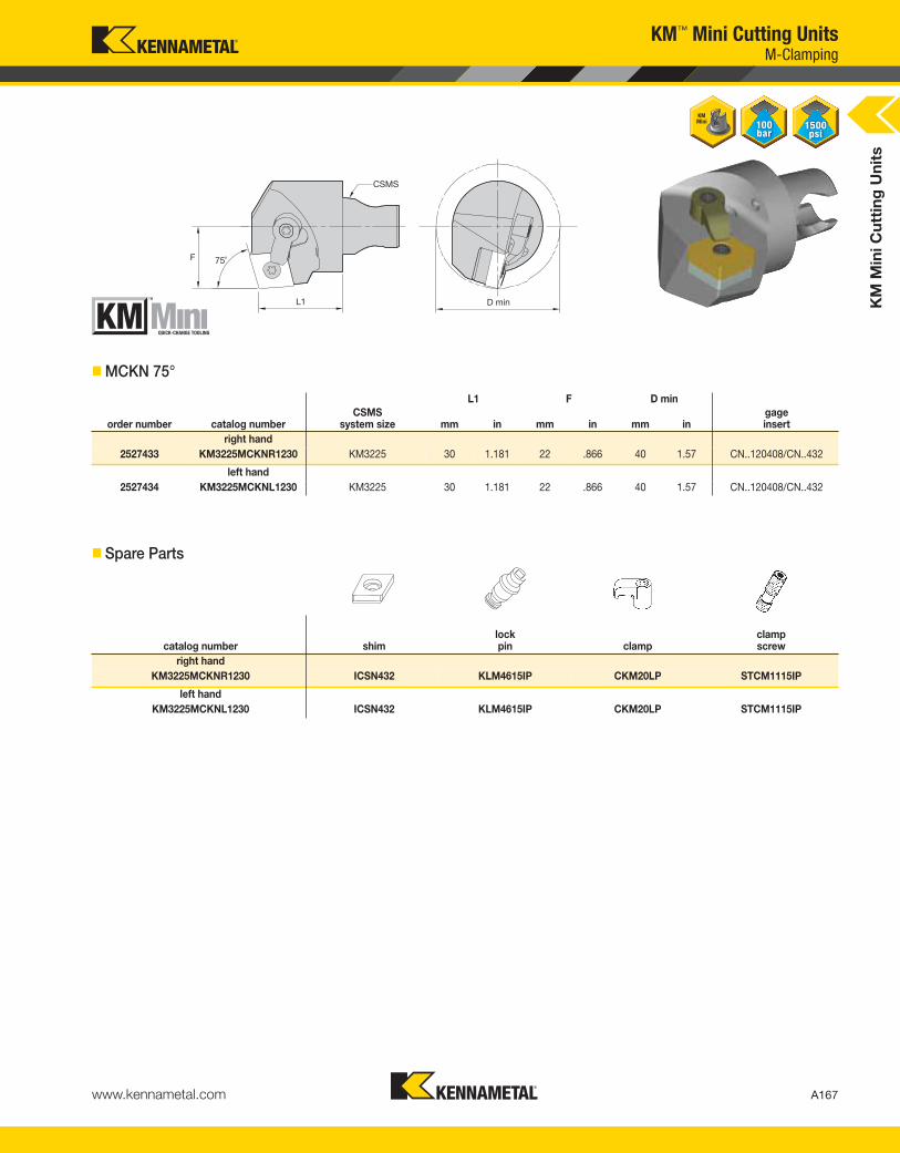
L1 F D min
order number catalog numberCSMS
system size mm in mm in mm ingageinsert
right hand
2527433 KM3225MCKNR1230 KM3225 30 1.181 22 .866 40 1.57 CN..120408/CN..432
left hand
2527434 KM3225MCKNL1230 KM3225 30 1.181 22 .866 40 1.57 CN..120408/CN..432
KM
Min
i C
utt
ing
Un
its
A167www.kennametal.com
KM™ Mini Cutting Units
� MCKN 75°
� Spare Parts
catalog number shimlock pin clamp
clampscrew
right hand
KM3225MCKNR1230 ICSN432 KLM4615IP CKM20LP STCM1115IP
left hand
KM3225MCKNL1230 ICSN432 KLM4615IP CKM20LP STCM1115IP
M-Clamping
KEN_TOOLINGSYSTEMS11_A166_A167.qxp:WIDIA 9:46 AM Page A167

KM
Min
i C
utt
ing
Un
its
A168 www.kennametal.com
KM™ Mini Cutting Units
� MCLN 95°
L1 F D min
order number catalog numberCSMS
system size mm in mm in mm ingageinsert
right hand
3503780 KM2520MCLNR0925 KM2520 25 .984 17 .669 32 1.260 CN..090308/CN..332
3503782 KM2520MCLNR1225 KM2520 25 .984 17 .669 32 1.260 CN..120408/CN..432
2527435 KM3225MCLNR0930 KM3225 30 1.181 22 .866 40 1.575 CN..090308/CN..322
2527437 KM3225MCLNR1230 KM3225 30 1.181 22 .866 40 1.575 CN..120408/CN..432
left hand
3503779 KM2520MCLNL0925 KM2520 25 .984 17 .669 32 1.260 CN..090308/CN..332
3503781 KM2520MCLNL1225 KM2520 25 .984 17 .669 32 1.260 CN..120408/CN..432
2527436 KM3225MCLNL0930 KM3225 30 1.181 22 .866 40 1.575 CN..090308/CN..322
2527438 KM3225MCLNL1230 KM3225 30 1.181 22 .866 40 1.575 CN..120408/CN..432
� Spare Parts
catalog number shimlock pin clamp
clampscrew
right hand
KM2520MCLNR0925 — KLM33 CKM7LP STCM38
KM2520MCLNR1225 — KLM43 CKM20LP STCM35
KM3225MCLNR0930 ICSN332 KLM34LT9PKG CKM7LP STCM9T9
KM3225MCLNR1230 ICSN432 KLM4615IP CKM20LP STCM1115IP
left hand
KM2520MCLNL0925 — KLM33 CKM7LP STCM38
KM2520MCLNL1225 — KLM43 CKM20LP STCM35
KM3225MCLNL0930 ICSN332 KLM34LT9PKG CKM7LP STCM9T9
KM3225MCLNL1230 ICSN432 KLM4615IP CKM20LP STCM1115IP
M-Clamping
KEN_TOOLINGSYSTEMS11_A168_A169.qxp:WIDIA 9:46 AM Page A168
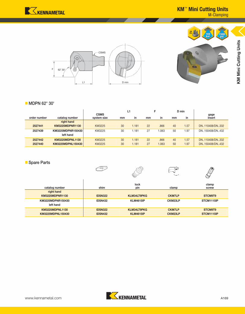
KM
Min
i C
utt
ing
Un
its
A169www.kennametal.com
KM™ Mini Cutting Units
� MDPN 62° 30'
� Spare Parts
catalog number shimlock pin clamp
clampscrew
right hand
KM3225MDPNR1130 IDSN322 KLM34LT9PKG CKM7LP STCM9T9
KM3225MDPNR150430 IDSN432 KLM4615IP CKM23LP STCM1115IP
left hand
KM3225MDPNL1130 IDSN322 KLM34LT9PKG CKM7LP STCM9T9
KM3225MDPNL150430 IDSN432 KLM4615IP CKM23LP STCM1115IP
M-Clamping
L1 F D min
order number catalog numberCSMS
system size mm in mm in mm ingageinsert
right hand
2527441 KM3225MDPNR1130 KM3225 30 1.181 22 .866 40 1.57 DN..110408/DN..332
2527439 KM3225MDPNR150430 KM3225 30 1.181 27 1.063 50 1.97 DN..150408/DN..432
left hand
2527442 KM3225MDPNL1130 KM3225 30 1.181 22 .866 40 1.57 DN..110408/DN..332
2527440 KM3225MDPNL150430 KM3225 30 1.181 27 1.063 50 1.97 DN..150408/DN..432
KEN_TOOLINGSYSTEMS11_A168_A169.qxp:WIDIA 9:46 AM Page A169

KM
Min
i C
utt
ing
Un
its
A170 www.kennametal.com
KM™ Mini Cutting Units
� MDQN 107° 30'
� Spare Parts
catalog number shimlock pin clamp
clampscrew
right hand
KM3225MDQNR1130 IDSN322 KLM34LT9PKG CKM7LP STCM9T9
KM3225MDQNR150430 IDSN432 KLM4615IP CKM20LP STCM1115IP
left hand
KM3225MDQNL1130 IDSN322 KLM34LT9PKG CKM7LP STCM9T9
KM3225MDQNL150430 IDSN432 KLM4615IP CKM20LP STCM1115IP
M-Clamping
L1 F D min
order number catalog numberCSMS
system size mm in mm in mm ingageinsert
right hand
2527445 KM3225MDQNR1130 KM3225 30 1.181 22 .866 40 1.57 DN..110408/DN..332
2527443 KM3225MDQNR150430 KM3225 30 1.181 22 .866 40 1.57 DN..150408/DN..432
left hand
2527446 KM3225MDQNL1130 KM3225 30 1.181 22 .866 40 1.57 DN..110408/DN..332
2527444 KM3225MDQNL150430 KM3225 30 1.181 22 .866 40 1.57 DN..150408/DN..432
KEN_TOOLINGSYSTEMS11_A170_A171.qxp:WIDIA 9:46 AM Page A170
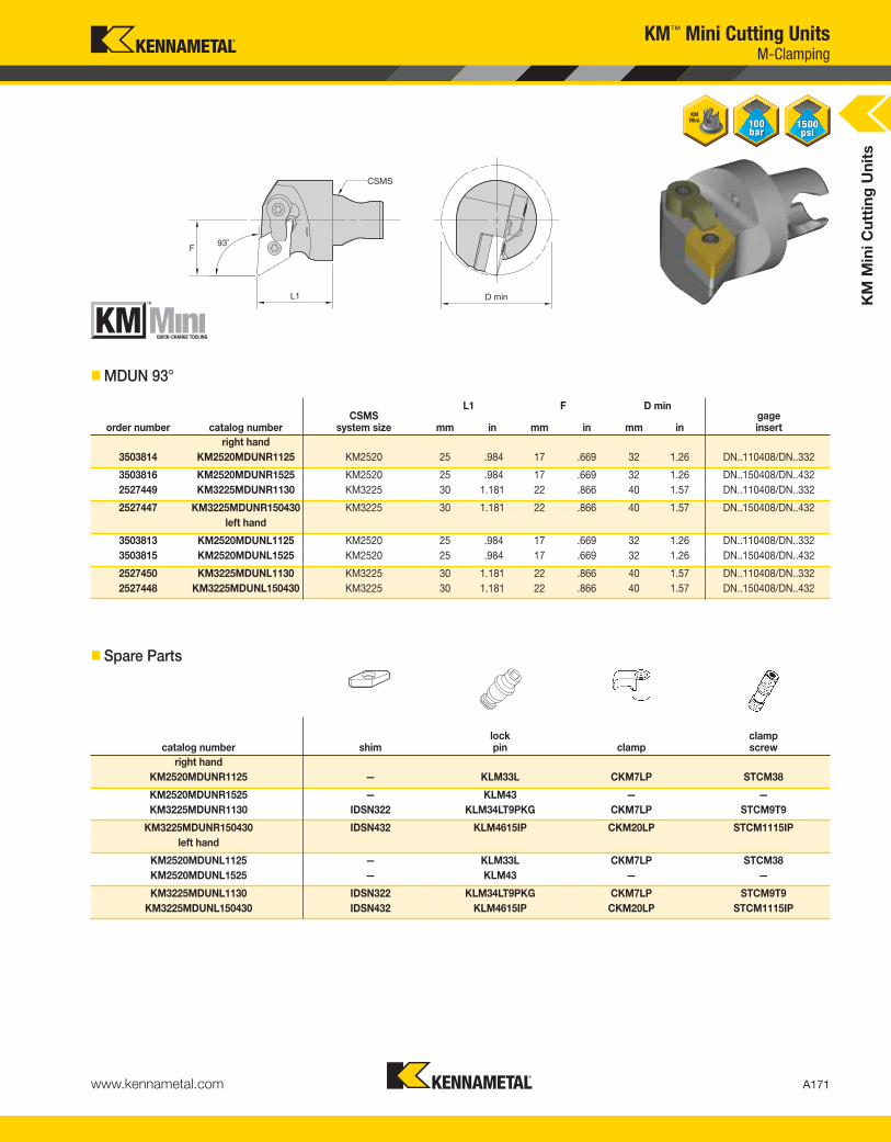
KM
Min
i C
utt
ing
Un
its
A171www.kennametal.com
KM™ Mini Cutting Units
� MDUN 93°
L1 F D min
order number catalog numberCSMS
system size mm in mm in mm ingageinsert
right hand
3503814 KM2520MDUNR1125 KM2520 25 .984 17 .669 32 1.26 DN..110408/DN..332
3503816 KM2520MDUNR1525 KM2520 25 .984 17 .669 32 1.26 DN..150408/DN..432
2527449 KM3225MDUNR1130 KM3225 30 1.181 22 .866 40 1.57 DN..110408/DN..332
2527447 KM3225MDUNR150430 KM3225 30 1.181 22 .866 40 1.57 DN..150408/DN..432
left hand
3503813 KM2520MDUNL1125 KM2520 25 .984 17 .669 32 1.26 DN..110408/DN..332
3503815 KM2520MDUNL1525 KM2520 25 .984 17 .669 32 1.26 DN..150408/DN..432
2527450 KM3225MDUNL1130 KM3225 30 1.181 22 .866 40 1.57 DN..110408/DN..332
2527448 KM3225MDUNL150430 KM3225 30 1.181 22 .866 40 1.57 DN..150408/DN..432
� Spare Parts
catalog number shimlock pin clamp
clampscrew
right hand
KM2520MDUNR1125 — KLM33L CKM7LP STCM38
KM2520MDUNR1525 — KLM43 — —
KM3225MDUNR1130 IDSN322 KLM34LT9PKG CKM7LP STCM9T9
KM3225MDUNR150430 IDSN432 KLM4615IP CKM20LP STCM1115IP
left hand
KM2520MDUNL1125 — KLM33L CKM7LP STCM38
KM2520MDUNL1525 — KLM43 — —
KM3225MDUNL1130 IDSN322 KLM34LT9PKG CKM7LP STCM9T9
KM3225MDUNL150430 IDSN432 KLM4615IP CKM20LP STCM1115IP
M-Clamping
KEN_TOOLINGSYSTEMS11_A170_A171.qxp:WIDIA 9:46 AM Page A171

KM
Min
i C
utt
ing
Un
its
A172 www.kennametal.com
KM™ Mini Cutting Units
� MSKN 75°
� Spare Parts
L1 F D min
order number catalog numberCSMS
system size mm in mm in mm ingageinsert
right hand
3503818 KM2520MSKNR1225 KM2520 25 .984 17 .669 32 1.26 SN..120408/SN..432
2527451 KM3225MSKNR1230 KM3225 30 1.181 22 .866 40 1.57 SN..120408/SN..432
left hand
3503817 KM2520MSKNL1225 KM2520 25 .984 17 .669 32 1.26 SN..120408/SN..432
2527452 KM3225MSKNL1230 KM3225 30 1.181 22 .866 40 1.57 SN..120408/SN..432
catalog number shimlock pin clamp
clampscrew
right hand
KM2520MSKNR1225 — KLM43 CKM20LP STCM11
KM3225MSKNR1230 ISSN432 KLM4615IP CKM20LP STCM1115IP
left hand
KM2520MSKNL1225 — KLM43 CKM20LP STCM11
KM3225MSKNL1230 ISSN432 KLM4615IP CKM20LP STCM1115IP
M-Clamping
KEN_TOOLINGSYSTEMS11_A172_A173.qxp:WIDIA 9:46 AM Page A172
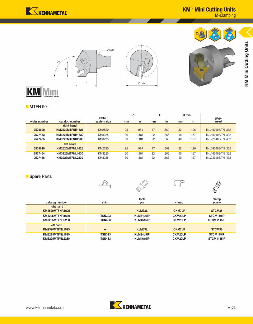
KM
Min
i C
utt
ing
Un
its
A173www.kennametal.com
KM™ Mini Cutting Units
L1 F D min
order number catalog numberCSMS
system size mm in mm in mm ingageinsert
right hand
3503820 KM2520MTFNR1625 KM2520 25 .984 17 .669 32 1.26 TN..160408/TN..332
2527453 KM3225MTFNR1630 KM3225 30 1.181 22 .866 40 1.57 TN..160408/TN..332
2527455 KM3225MTFNR2230 KM3225 30 1.181 22 .866 40 1.57 TN..220408/TN..432
left hand
3503819 KM2520MTFNL1625 KM2520 25 .984 17 .669 32 1.26 TN..160408/TN..332
2527454 KM3225MTFNL1630 KM3225 30 1.181 22 .866 40 1.57 TN..160408/TN..332
2527456 KM3225MTFNL2230 KM3225 30 1.181 22 .866 40 1.57 TN..220408/TN..432
� Spare Parts
catalog number shimlock pin clamp
clampscrew
right hand
KM2520MTFNR1625 — KLM33L CKM7LP STCM38
KM3225MTFNR1630 ITSN323 KLM34L9IP CKM20LP STCM119IP
KM3225MTFNR2230 ITSN433 KLM4615IP CKM20LP STCM1115IP
left hand
KM2520MTFNL1625 — KLM33L CKM7LP STCM38
KM3225MTFNL1630 ITSN323 KLM34L9IP CKM20LP STCM119IP
KM3225MTFNL2230 ITSN433 KLM4615IP CKM20LP STCM1115IP
� MTFN 90°
M-Clamping
KEN_TOOLINGSYSTEMS11_A172_A173.qxp:WIDIA 9:47 AM Page A173
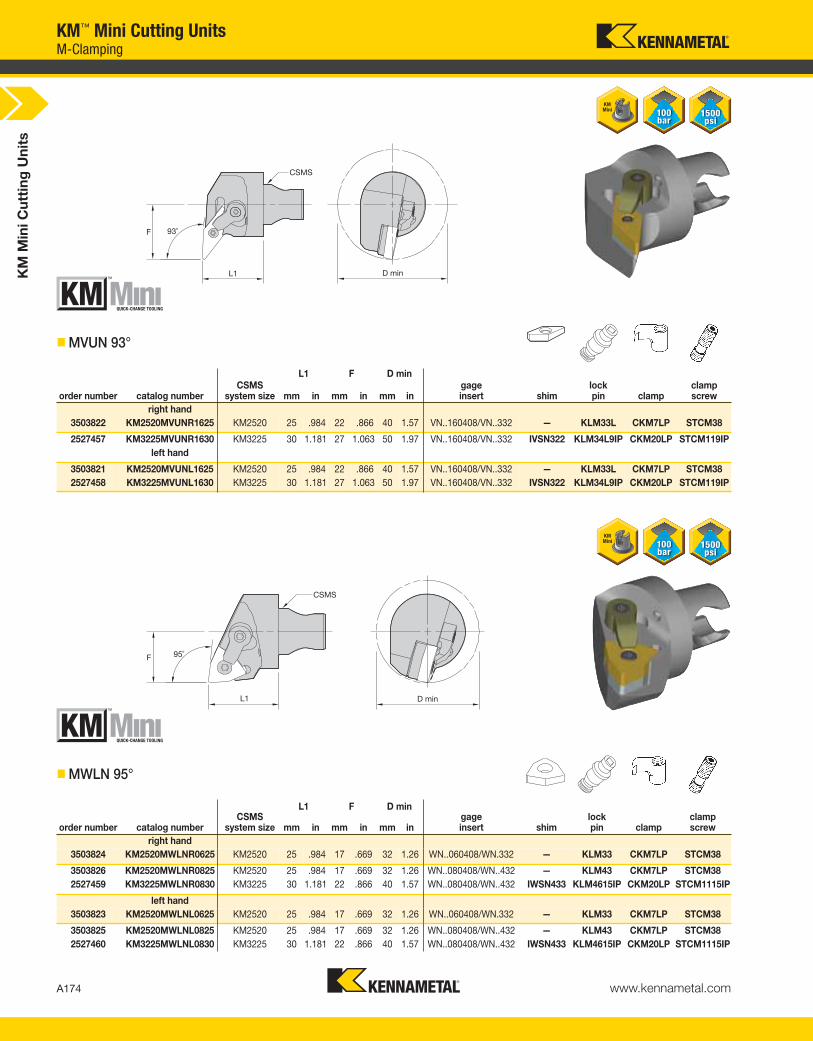
KM
Min
i C
utt
ing
Un
its
A174 www.kennametal.com
KM™ Mini Cutting Units
L1 F D min
order number catalog numberCSMS
system size mm in mm in mm ingageinsert shim
lock pin clamp
clampscrew
right hand
3503822 KM2520MVUNR1625 KM2520 25 .984 22 .866 40 1.57 VN..160408/VN..332 — KLM33L CKM7LP STCM38
2527457 KM3225MVUNR1630 KM3225 30 1.181 27 1.063 50 1.97 VN..160408/VN..332 IVSN322 KLM34L9IP CKM20LP STCM119IP
left hand
3503821 KM2520MVUNL1625 KM2520 25 .984 22 .866 40 1.57 VN..160408/VN..332 — KLM33L CKM7LP STCM38
2527458 KM3225MVUNL1630 KM3225 30 1.181 27 1.063 50 1.97 VN..160408/VN..332 IVSN322 KLM34L9IP CKM20LP STCM119IP
L1 F D min
order number catalog numberCSMS
system size mm in mm in mm ingageinsert shim
lock pin clamp
clampscrew
right hand
3503824 KM2520MWLNR0625 KM2520 25 .984 17 .669 32 1.26 WN..060408/WN.332 — KLM33 CKM7LP STCM38
3503826 KM2520MWLNR0825 KM2520 25 .984 17 .669 32 1.26 WN..080408/WN..432 — KLM43 CKM7LP STCM38
2527459 KM3225MWLNR0830 KM3225 30 1.181 22 .866 40 1.57 WN..080408/WN..432 IWSN433 KLM4615IP CKM20LP STCM1115IP
left hand
3503823 KM2520MWLNL0625 KM2520 25 .984 17 .669 32 1.26 WN..060408/WN.332 — KLM33 CKM7LP STCM38
3503825 KM2520MWLNL0825 KM2520 25 .984 17 .669 32 1.26 WN..080408/WN..432 — KLM43 CKM7LP STCM38
2527460 KM3225MWLNL0830 KM3225 30 1.181 22 .866 40 1.57 WN..080408/WN..432 IWSN433 KLM4615IP CKM20LP STCM1115IP
� MVUN 93°
� MWLN 95°
M-Clamping
KEN_TOOLINGSYSTEMS11_A174_A175.qxp:WIDIA 9:47 AM Page A174

KM
Min
i C
utt
ing
Un
its
A175www.kennametal.com
L1 F D min
order number catalog numberCSMS
system size mm in mm in mm ingageinsert shim
leverscrew
shimpin
togglelever punch
right hand
3482970 KM2520PCLNR1225 KM2520 25 .984 17 .669 32 1.26 CN..120408/CN..432 — 514.122 — 511.022 —
2527461 KM3225PCLNR1230 KM3225 30 1.181 22 .866 40 1.57 CN..120408/CN..432 512.112 514.123 513.023 511.023 515.018
left hand
3482969 KM2520PCLNL1225 KM2520 25 .984 17 .669 32 1.26 CN..120408/CN..432 — 514.122 — 511.022 —
2527462 KM3225PCLNL1230 KM3225 30 1.181 22 .866 40 1.57 CN..120408/CN..432 512.112 514.123 513.023 511.023 515.018
KM™ Mini Cutting Units
L1 F D min
order number catalog numberCSMS
system size mm in mm in mm ingageinsert shim
leverscrew
shimpin
togglelever punch
right hand
3482972 KM2520PDUNR1125 KM2520 25 .984 17 .669 32 1.26 DN..110408/DN..332 512.060 514.118 513.060 511.060 515.018
2527463 KM3225PDUNR1130 KM3225 30 1.181 22 .866 40 1.57 DN..110408/DN..332 512.060 514.118 513.060 511.060 515.018
left hand
3482971 KM2520PDUNL1125 KM2520 25 .984 17 .669 32 1.26 DN..110408/DN..332 512.060 514.118 513.060 511.060 515.018
2527464 KM3225PDUNL1130 KM3225 30 1.181 22 .866 40 1.57 DN..110408/DN..332 512.060 514.118 513.060 511.060 515.018
� PCLN 95°
� PDUN 93°
P-Clamping
KEN_TOOLINGSYSTEMS11_A174_A175.qxp:WIDIA 9:47 AM Page A175

KM
Min
i C
utt
ing
Un
its
A176 www.kennametal.com
KM™ Mini Cutting Units
L1 F D min
order number catalog numberCSMS
system size mm in mm in mm ingageinsert shim
leverscrew
shimpin
togglelever punch
right hand
3483024 KM2520PWLNR0625 KM2520 25 .984 17 .669 32 1.26 WN..060408/WN..332 — 514.112 — 511.030 —
2527465 KM3225PWLNR0830 KM3225 30 1.181 22 .866 40 1.57 WN..080408/WN..432 512.135 514.123 513.023 511.023 515.018
left hand
3483023 KM2520PWLNL0625 KM2520 25 .984 17 .669 32 1.26 WN..060408/WN..332 — 514.112 — 511.030 —
2527466 KM3225PWLNL0830 KM3225 30 1.181 22 .866 40 1.57 WN..080408/WN..432 512.135 514.123 513.023 511.023 515.018
� PWLN 95°
P-Clamping
KEN_TOOLINGSYSTEMS11_A176_A177.qxp:WIDIA 9:47 AM Page A176
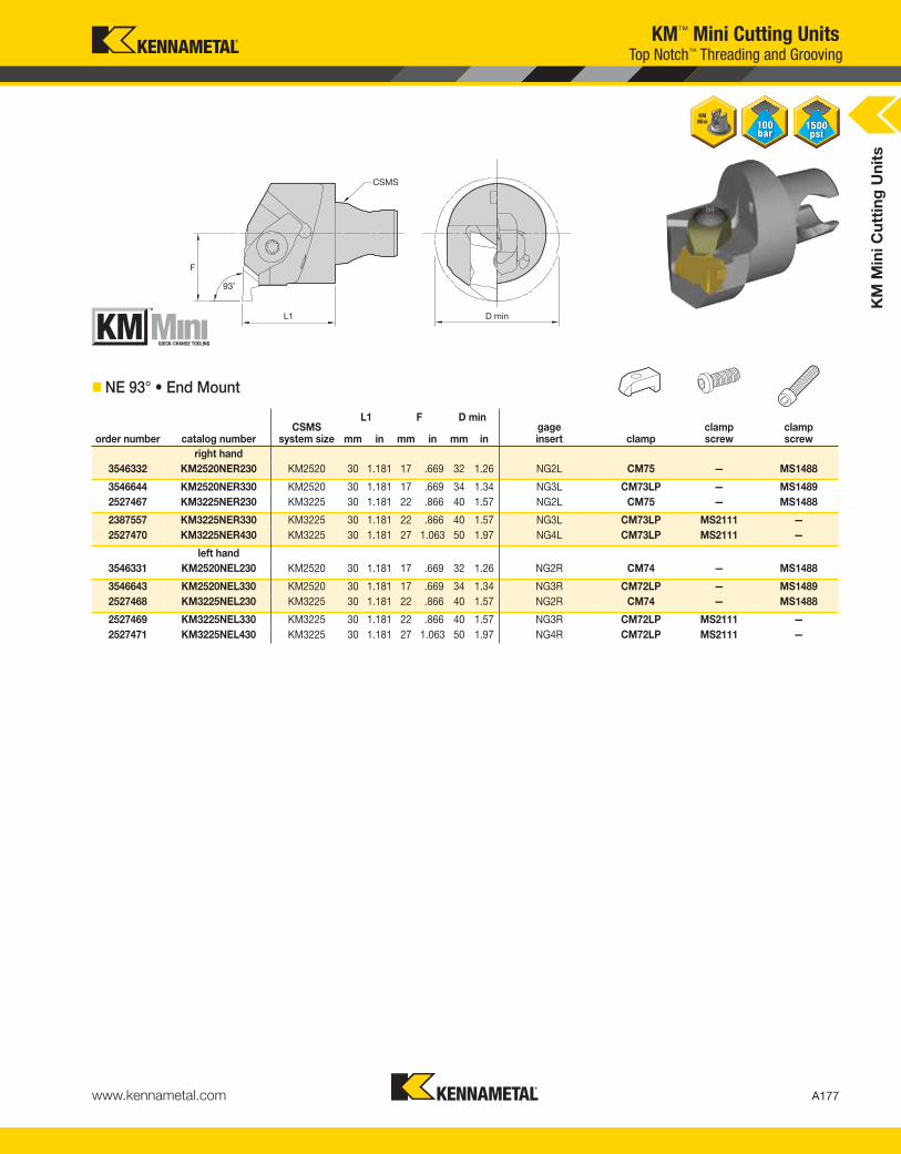
L1 F D min
order number catalog numberCSMS
system size mm in mm in mm ingageinsert clamp
clampscrew
clampscrew
right hand
3546332 KM2520NER230 KM2520 30 1.181 17 .669 32 1.26 NG2L CM75 — MS1488
3546644 KM2520NER330 KM2520 30 1.181 17 .669 34 1.34 NG3L CM73LP — MS1489
2527467 KM3225NER230 KM3225 30 1.181 22 .866 40 1.57 NG2L CM75 — MS1488
2387557 KM3225NER330 KM3225 30 1.181 22 .866 40 1.57 NG3L CM73LP MS2111 —
2527470 KM3225NER430 KM3225 30 1.181 27 1.063 50 1.97 NG4L CM73LP MS2111 —
left hand
3546331 KM2520NEL230 KM2520 30 1.181 17 .669 32 1.26 NG2R CM74 — MS1488
3546643 KM2520NEL330 KM2520 30 1.181 17 .669 34 1.34 NG3R CM72LP — MS1489
2527468 KM3225NEL230 KM3225 30 1.181 22 .866 40 1.57 NG2R CM74 — MS1488
2527469 KM3225NEL330 KM3225 30 1.181 22 .866 40 1.57 NG3R CM72LP MS2111 —
2527471 KM3225NEL430 KM3225 30 1.181 27 1.063 50 1.97 NG4R CM72LP MS2111 —
KM
Min
i C
utt
ing
Un
its
A177www.kennametal.com
KM™ Mini Cutting UnitsTop Notch™ Threading and Grooving
� NE 93° • End Mount
KEN_TOOLINGSYSTEMS11_A176_A177.qxp:WIDIA 9:47 AM Page A177
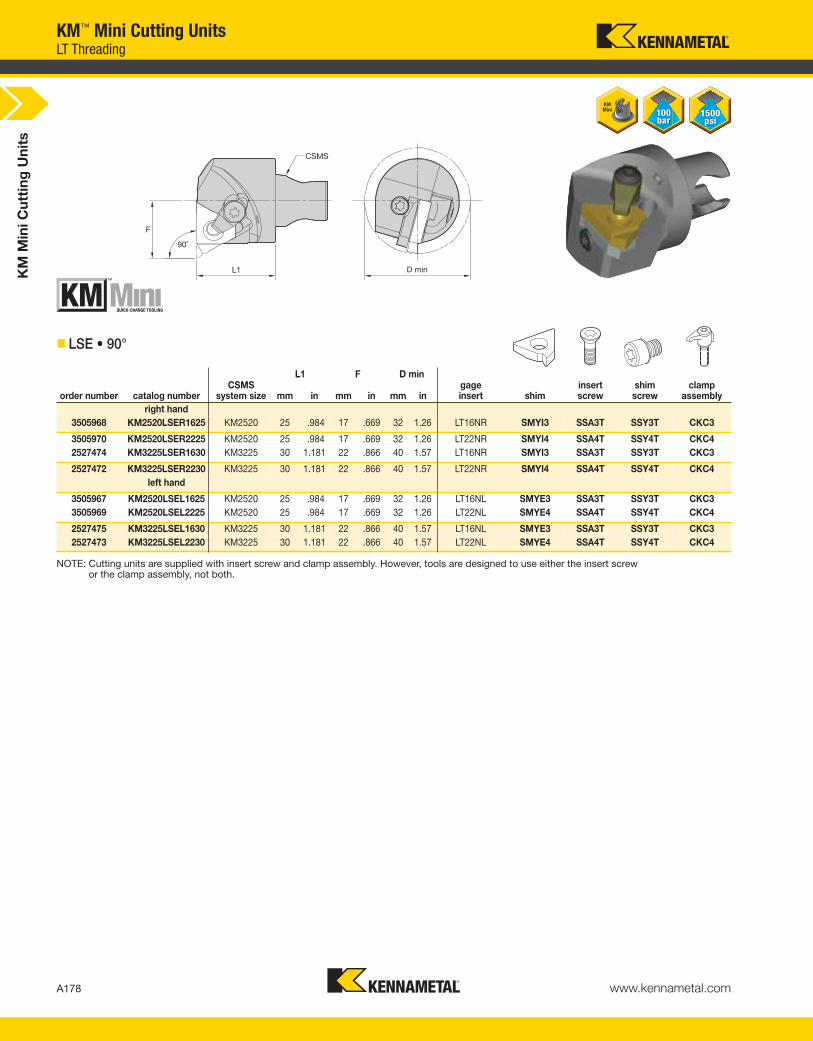
KM
Min
i C
utt
ing
Un
its
A178 www.kennametal.com
KM™ Mini Cutting UnitsLT Threading
NOTE: Cutting units are supplied with insert screw and clamp assembly. However, tools are designed to use either the insert screw or the clamp assembly, not both.
L1 F D min
order number catalog numberCSMS
system size mm in mm in mm ingageinsert shim
insert screw
shim screw
clamp assembly
right hand
3505968 KM2520LSER1625 KM2520 25 .984 17 .669 32 1.26 LT16NR SMYI3 SSA3T SSY3T CKC3
3505970 KM2520LSER2225 KM2520 25 .984 17 .669 32 1.26 LT22NR SMYI4 SSA4T SSY4T CKC4
2527474 KM3225LSER1630 KM3225 30 1.181 22 .866 40 1.57 LT16NR SMYI3 SSA3T SSY3T CKC3
2527472 KM3225LSER2230 KM3225 30 1.181 22 .866 40 1.57 LT22NR SMYI4 SSA4T SSY4T CKC4
left hand
3505967 KM2520LSEL1625 KM2520 25 .984 17 .669 32 1.26 LT16NL SMYE3 SSA3T SSY3T CKC3
3505969 KM2520LSEL2225 KM2520 25 .984 17 .669 32 1.26 LT22NL SMYE4 SSA4T SSY4T CKC4
2527475 KM3225LSEL1630 KM3225 30 1.181 22 .866 40 1.57 LT16NL SMYE3 SSA3T SSY3T CKC3
2527473 KM3225LSEL2230 KM3225 30 1.181 22 .866 40 1.57 LT22NL SMYE4 SSA4T SSY4T CKC4
� LSE • 90°
KEN_TOOLINGSYSTEMS11_A178_A179.qxp:WIDIA 9:47 AM Page A178

A179www.kennametal.com
At Kennametal, innovation follows vision. Our revolutionary products and services are inspired by asking “what if?” The solutions that follow — like our Beyond BLAST through-coolant inserts — deliver remarkableresults in the world’s most demanding machining environments.
A cutting-edge insert that delivers coolant precisely at the cutting edge. Now that’s Different Thinking. That’s Kennametal.
To learn more about your productivity gains using Beyond BLAST technology, visit www.kennametal.com.
More than just the right tool • the ultimate solution.
That’s Beyond BLAST.™
That’s Different Thinking.
Milling• Beyond BLAST technology uses low-pressure conditions to offer many
of the high-pressure performance benefits.
• Delivers superior performance on titanium, using either high- or low-pressure
coolant systems.
• Effective thermal management results in reduced cutting temperatures, improved
lubricity, superior chip control, and longer tool life.
• Beyond BLAST for milling increases tool life by up to 300% compared with
conventional coolant delivery systems.
To learn more, scan here.
For instructions on how to scan,
please see page xxxiii.
KEN_TOOLINGSYSTEMS11_A178_A179.qxp:WIDIA 9:47 AM Page A179

L1S F D min W min CD
order number catalog numberCSMS
system sizeseatsize mm in mm in mm in mm in mm in
right hand
3503887 KM2520A4EMR0108M25 KM2520 1 24 .955 22 .866 40 1.57 1,50 .059 8 .32
3503885 KM2520A4EMR0208M25 KM2520 2 24 .945 22 .866 40 1.57 2,00 .079 8 .32
3503871 KM2520A4EMR0308M25 KM2520 3 24 .925 22 .866 40 1.57 3,00 .118 8 .32
3503869 KM2520A4EMR0408M25 KM2520 4 23 .906 22 .866 40 1.57 4,00 .157 8 .32
3503883 KM2520A4EMR2B08M25 KM2520 2B 24 .935 22 .866 40 1.57 2,50 .098 8 .32
2527482 KM3225A4EMR0310M30 KM3225 3 29 1.122 27 1.063 50 1.97 3,00 .118 10 .40
2527484 KM3225A4EMR0410M30 KM3225 4 28 1.102 27 1.063 50 1.97 4,00 .157 10 .40
2527488 KM3225A4EMR0510M30 KM3225 5 28 1.083 27 1.063 50 1.97 5,00 .197 10 .40
left hand
3503886 KM2520A4EML0108M25 KM2520 1 24 .955 22 .866 40 1.57 1,50 .059 8 .32
3503884 KM2520A4EML0208M25 KM2520 2 24 .945 22 .866 40 1.57 2,00 .079 8 .32
3503870 KM2520A4EML0308M25 KM2520 3 24 .925 22 .866 40 1.57 3,00 .118 8 .32
3503868 KM2520A4EML0408M25 KM2520 4 23 .906 22 .866 40 1.57 4,00 .157 8 .32
3503872 KM2520A4EML2B08M25 KM2520 2B 24 .935 22 .866 40 1.57 2,50 .098 8 .32
2527483 KM3225A4EML0310M30 KM3225 3 29 1.122 27 1.063 50 1.97 3,00 .118 10 .40
2527485 KM3225A4EML0410M30 KM3225 4 28 1.102 27 1.063 50 1.97 4,00 .157 10 .40
2527489 KM3225A4EML0510M30 KM3225 5 28 1.083 27 1.063 50 1.97 5,00 .197 10 .40
KM
Min
i C
utt
ing
Un
its
A180 www.kennametal.com
KM™ Mini Cutting UnitsA4™ Grooving
� A4EM • End Mount
(continued)
KEN_TOOLINGSYSTEMS11_A180_A181.qxp:WIDIA 9:47 AM Page A180

KM
Min
i C
utt
ing
Un
its
A181www.kennametal.com
� Spare Parts
catalog numberclampscrew
clampscrew
right hand
KM2520A4EMR0108M25 MS1156 —
KM2520A4EMR0208M25 — MS1160
KM2520A4EMR0308M25 — MS1161
KM2520A4EMR0408M25 — MS1161
KM2520A4EMR2B08M25 — MS1160
KM3225A4EMR0310M30 MS2069 —
KM3225A4EMR0410M30 MS2069 —
KM3225A4EMR0510M30 MS2069 —
left hand
KM2520A4EML0108M25 MS1156 —
KM2520A4EML0208M25 — MS1160
KM2520A4EML0308M25 — MS1161
KM2520A4EML0408M25 — MS1161
KM2520A4EML2B08M25 — MS1160
KM3225A4EML0310M30 MS2069 —
KM3225A4EML0410M30 MS2069 —
KM3225A4EML0510M30 MS2069 —
NOTE: W min supplied for reference only. See the Kennametal Innovations Master Catalog Cutting Tools 2013 for actual insert width. Always match seat size of insert to seat size of holder.Seat size 2B cutting units only accepts 2B inserts. Seat size 2 cutting units accepts 2 or 2B inserts.
KM™ Mini Cutting UnitsA4™ Grooving
(A4EM • End Mount continued)
KEN_TOOLINGSYSTEMS11_A180_A181.qxp:WIDIA 9:47 AM Page A181

KM
Min
i Cut
ting
Uni
ts
A182 www.kennametal.com
KM™ Mini Cutting UnitsA3™ Deep Grooving
� A3ES • End Mount
L1S F D min W min CD
order number catalog numberCSMS
system sizeseatsize mm in mm in mm in mm in mm in
right hand3503893 KM2520A3ESR0308M25 KM2520 3 24 .925 22 .866 40,0 1.575 3,0 .118 8 .32
3503891 KM2520A3ESR0408M25 KM2520 4 23 .906 22 .866 40,0 1.575 4,0 .157 8 .323503889 KM2520A3ESR0510M25 KM2520 5 23 .886 24 .945 40,0 1.575 5,0 .197 10 .39
2527476 KM3225A3ESR0305M30 KM3225 3 29 1.122 22 .866 40,0 1.575 3,0 .118 5 .212527478 KM3225A3ESR0408M30 KM3225 4 28 1.102 25 .984 42,0 1.654 4,0 .157 8 .32
2527480 KM3225A3ESR0510M30 KM3225 5 28 1.083 27 1.063 45,0 1.772 5,0 .197 10 .40left hand
3503892 KM2520A3ESL0308M25 KM2520 3 24 .925 22 .866 40,0 1.575 3,0 .118 8 .323503890 KM2520A3ESL0408M25 KM2520 4 23 .906 22 .866 40,0 1.575 4,0 .157 8 .32
3503888 KM2520A3ESL0510M25 KM2520 5 23 .886 24 .945 40,0 1.575 5,0 .197 10 .392527477 KM3225A3ESL0305M30 KM3225 3 29 1.122 22 .866 40,0 1.575 3,0 .118 5 .21
2527479 KM3225A3ESL0408M30 KM3225 4 28 1.102 25 .984 42,0 1.654 4,0 .157 8 .322527481 KM3225A3ESL0510M30 KM3225 5 28 1.083 27 1.063 45,0 1.772 5,0 .197 10 .40
NOTE: W min supplied for reference only. See the Kennametal Innovations Master Catalog Cutting Tools 2013 for actual insert width. Always match seat size of insert to seat size of holder.
catalog numberclampscrew
right handKM2520A3ESR0308M25 MS2064
KM2520A3ESR0408M25 MS2064KM2520A3ESR0510M25 MS1162
KM3225A3ESR0305M30 MS2064KM3225A3ESR0408M30 MS2064
KM3225A3ESR0510M30 MS2062left hand
KM2520A3ESL0308M25 MS2064KM2520A3ESL0408M25 MS2064
KM2520A3ESL0510M25 MS1162KM3225A3ESL0305M30 MS2064
KM3225A3ESL0408M30 MS2064KM3225A3ESL0510M30 MS2062
� Spare Parts
KEN_TOOLINGSYSTEMS11_A182_A183.qxp:WIDIA 2:09 PM Page A182
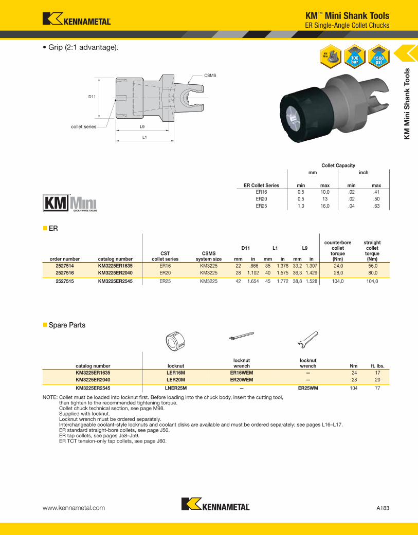
KM
Min
i Sha
nk T
oo
ls
A183www.kennametal.com
KM™ Mini Shank ToolsER Single-Angle Collet Chucks
• Grip (2:1 advantage).
collet series
� ER
Collet Capacitymm inch
ER Collet Series min max min maxER16 0,5 10,0 .02 .41ER20 0,5 13 .02 .50ER25 1,0 16,0 .04 .63
D11 L1 L9
order number catalog numberCST
collet seriesCSMS
system size mm in mm in mm in
counterbore collet torque (Nm)
straight collettorque (Nm)
2527514 KM3225ER1635 ER16 KM3225 22 .866 35 1.378 33,2 1.307 24,0 56,02527516 KM3225ER2040 ER20 KM3225 28 1.102 40 1.575 36,3 1.429 28,0 80,0
2527515 KM3225ER2545 ER25 KM3225 42 1.654 45 1.772 38,8 1.528 104,0 104,0
� Spare Parts
NOTE: Collet must be loaded into locknut first. Before loading into the chuck body, insert the cutting tool, then tighten to the recommended tightening torque.Collet chuck technical section, see page M98.Supplied with locknut.Locknut wrench must be ordered separately.Interchangeable coolant-style locknuts and coolant disks are available and must be ordered separately; see pages L16–L17.ER standard straight-bore collets, see page J50.ER tap collets, see pages J58–J59.ER TCT tension-only tap collets, see page J60.
catalog number locknutlocknut wrench
locknut wrench Nm ft. lbs.
KM3225ER1635 LER16M ER16WEM — 24 17KM3225ER2040 LER20M ER20WEM — 28 20
KM3225ER2545 LNER25M — ER25WM 104 77
KEN_TOOLINGSYSTEMS11_A182_A183.qxp:WIDIA 2:09 PM Page A183

KM
Min
i S
ha
nk
To
ols
A184 www.kennametal.com
KM™ Mini Shank ToolsBoring Bar Adapters
� BA • Boring Bar Adapter • Metric
order number catalog numberCSMS
system size D1 D2 L1 L9clampscrew
clampscrew
wrench size clamp screw Nm
2527505 KM3225BA0645M KM3225 6 32 45 36 MS734 — 2,5mm 4
3507964 KM2520BA0645M KM2520 6 25 45 36 — MS1272 2,5mm 4
3507963 KM2520BA0845M KM2520 8 25 45 36 — MS1272 2,5mm 4
2527506 KM3225BA0845M KM3225 8 32 45 36 MS734 — 2,5mm 4
3505972 KM2520BA1055M KM2520 10 30 55 48 — MS-1879 4mm 15
2527507 KM3225BA1055M KM3225 10 32 55 48 MS1205 MS-1879 4mm 15
2527508 KM3225BA1260M KM3225 12 32 60 52 MS1205 MS-1879 4mm 15
3505971 KM2520BA1260M KM2520 12 32 60 52 — MS-1879 4mm 15
2527509 KM3225BA1665M KM3225 16 34 65 55 MS1205 — 5mm 25
2527510 KM3225BA2070M KM3225 20 37 70 58 MS1205 — 5mm 25
� BA • Boring Bar Adapter • Inch
order number catalog numberCSMS
system size D1 D2 L1 L9clampscrew
wrench size clamp screw ft. lbs.
3507967 KM2520BA04217 KM2520 1/4 .98 1.378 1.06 — 3/32 2
3507966 KM2520BA06217 KM2520 3/8 1.10 2.165 1.89 S841PKG 1/8 5
3507965 KM2520BA08236 KM2520 1/2 1.26 2.362 2.05 S850 5/32 11
2527490 KM3225BA06217 KM3225 3/8 1.26 2.165 1.89 MS1205 1/8 5
2527491 KM3225BA08236 KM3225 1/2 1.26 2.362 2.05 S850 5/32 11
2527492 KM3225BA10256 KM3225 5/8 1.34 2.559 2.13 S861 3/16 15
2527503 KM3225BA12276 KM3225 3/4 1.46 2.756 2.28 S861 3/16 15
NOTE: Do not overtighten clamp screw; use torque recommendations above.Supplied with clamp screw.Clamp screw wrench not included.
KEN_TOOLINGSYSTEMS11_A184_A185.qxp:WIDIA 9:48 AM Page A184
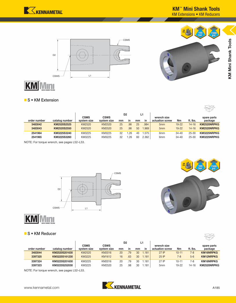
KM
Min
i S
ha
nk
To
ols
A185www.kennametal.com
D2 L1
order number catalog numberCSMS
system sizeCSWS
system size mm in mm inwrench size
actuation screw Nm ft. lbs.spare parts
package
3483042 KM2520S2525 KM2520 KM2520 25 .98 25 .984 5mm 19-22 14-16 KM2520NRPKG
3483043 KM2520S2550 KM2520 KM2520 25 .98 50 1.969 5mm 19-22 14-16 KM2520NRPKG
2541964 KM3225S3240 KM3225 KM3225 32 1.26 40 1.575 6mm 34-40 25-30 KM3225NRPKG
2541965 KM3225S3260 KM3225 KM3225 32 1.26 60 2.362 6mm 34-40 25-30 KM3225NRPKG
D2 L1
order number catalog numberCSMS
system sizeCSWS
system size mm in mm inwrench size
actuation screw Nm ft. lbs.spare parts
package
3483044 KM2520S201630 KM2520 KM2016 20 .79 30 1.181 27 IP 10-11 7-8 KM16NRPKG
3397325 KM3225S161230 KM3225 KM1612 16 .63 30 1.181 25 IP 7-8 5-6 KM12NRPKG
3397324 KM3225S201630 KM3225 KM2016 20 .79 30 1.181 27 IP 10-11 7-8 KM16NRPKG
3397323 KM3225S252030 KM3225 KM2520 25 .98 30 1.181 5mm 19-22 14-16 KM2520NRPKG
KM™ Mini Shank Tools
� S • KM Extension
NOTE: For torque wrench, see pages L52–L53.
� S • KM Reducer
NOTE: For torque wrench, see pages L52–L53.
KM Extensions • KM Reducers
KEN_TOOLINGSYSTEMS11_A184_A185.qxp:WIDIA 9:48 AM Page A185

KM
Min
i S
ha
nk
To
ols
A186 www.kennametal.com
KM™ Mini Shank Tools
� BN • Blank
D2 L1
order number catalog numberCSMS
system size mm in mm inhardness
range
3518531 KM20BN4040 KM20 40 1.575 40 1.575 38 - 42 RW C
3503896 KM2520BN5050 KM2520 50 1.969 50 1.969 38 - 42 RW C
2427296 KM25BN5050 KM25 50 1.969 50 1.969 38 - 42 RW C
2656551 KM3225BN5050 KM3225 50 1.969 50 1.969 38 - 42 RW C
� P • Plug
D2 L1
order number catalog numberCSMS
system size mm in mm in
3662590 KM20P KM20 20 .787 5 .197
3662591 KM2520P KM2520 25 .984 5 .197
2427295 KM25P KM25 25 .984 5 .197
2906995 KM3225P KM3225 32 1.260 5 .197
Blanks • Plugs
KEN_TOOLINGSYSTEMS11_A186_A187.qxp:WIDIA 9:48 AM Page A186

KM
Min
i S
ha
nk
To
ols
A187www.kennametal.com
KM™ Mini Shank ToolsGage Bars
� GB • Gage Bar
D2 L1 L13
order number catalog numberCSMS
system size mm in mm in mm in
3518635 KM20GB2525 KM20 25 .984 25 .984 25 .984
2427297 KM25GB3230 KM25 32 1.260 30 1.181 29 1.142
KEN_TOOLINGSYSTEMS11_A186_A187.qxp:WIDIA 9:48 AM Page A187

KM
Min
i S
ha
nk
To
ols
A188 www.kennametal.com
KM™ Mini Shank ToolsPresetter Adapters
� TRA • Centered
D1 D13 L1 Forder
numbercatalog number
CSMSsystem size
CSWS system size mm in mm in mm in mm in
KM spareparts package
wrench sizeactuation screw Nm ft. lbs.
3449331 CV50KM3225TRA CV50 KM3225 32 1.260 26 1.039 50 1.969 0,0 .000 KM3225NRPKG 6mm 34-40 25-30
3503898 DV40KM2520TRA DV40 KM2520 25 .984 18 .693 50 1.969 0,0 .000 KM2520NRPKG 5mm 19-22 14-16
3449332 DV40KM3225TRA DV40 KM3225 32 1.260 18 .693 50 1.969 0,0 .000 KM3225NRPKG 6mm 34-40 25-30
NOTE: These are only intended to be used in a presetter fixture.
� ECTRA • Offset
D1 D13 L1 Forder
numbercatalog number
CSMSsystem size
CSWS system size mm in mm in mm in mm in
KM spareparts package
wrench sizeactuation screw Nm ft. lbs.
3518634 CV50KM20ECTRA CV50 KM20 20 .787 26 1.014 50 1.969 9,5 .375 KM2520NRPKG 5mm 19-22 14-16
2427294 CV50KM25ECTRA CV50 KM25 25 .984 26 1.039 50 1.969 12,5 .492 KM25NRPKG 6mm 34-40 25-30
3518633 DV40KM20ECTRA DV40 KM20 20 .787 19 .728 50 1.969 9,5 .375 KM2520NRPKG 5mm 19-22 14-16
NOTE: These are only intended to be used in a presetter fixture.
KEN_TOOLINGSYSTEMS11_A188_A189.qxp:WIDIA 9:48 AM Page A188

KM
Min
i S
ha
nk
To
ols
A189www.kennametal.com
KM™ Mini Shank ToolsTumble Blocks
� TB • Tumble Block
D1 L1 H2 H3 B2 B1order
numbercatalognumber
CSWS system size mm in mm in mm in mm in mm in mm in
spare partspackage
wrench sizeactuation screw Nm ft. lbs.
3503897 KM2520TB KM2520 25 .984 76,20 3.000 64 2.520 32 1.260 64 2.520 32,00 1.260 KM2520NRPKG 5mm 19-22 14-16
3449353 KM3225TB KM3225 32 1.260 76,20 3.000 64 2.520 32 1.260 64 2.520 32,00 1.260 KM3225NRPKG 6mm 34-40 25-30
KEN_TOOLINGSYSTEMS11_A188_A189.qxp:WIDIA 9:48 AM Page A189