Embed Size (px)
Citation preview
Proceedings of IPACK03 International Electronic Packaging Technical Conference and Exhibition
July 6-11, 2003, Maui, Hawaii, USA
1 Copyright © 2003 by ASME
IPACK2003-35058
INKJET ASSISTED SPRAY COOLING OF ELECTRONICS
Cullen E. Bash, Chandrakant D. Patel, Ratnesh K. Sharma
Hewlett-Packard Laboratories
1501 Page Mill Road, M/S 1183 Palo Alto, California, 94304-1126
Phone (650) 236-2748, Fax (650) 857-7029, [email protected] Phone (650) 857-7140, Fax (650) 857-7029, [email protected] Phone (650) 857-3835, Fax (650) 857-7029, [email protected]
ABSTRACT
Increases in microprocessor power dissipation and the resulting effect on the cost and complexity of thermal management solutions has been well documented in recent years. Accompanying this increase in overall power dissipation has been a reduction in feature size due to process improvements resulting in a steady decrease in the size of the processing core where most of the power on a die is generated. This trend is expected to continue into the near future and will likely lead to a power dense core covering a fraction of the total die surface area surrounded by areas of reduced power density cache. Evaporative spray cooling has been long identified as a technology that can be used to manage very high power densities (> 100 W/cm2). Limitations in the controllability of individual spray droplets, however, have generally prevented its use in applications that contain marked variation in spatial power density. Since only a relatively uniform spray pattern is possible with existing spray delivery technologies, sections of lower power density become susceptible to pool boiling and thereby place limitations on bulk flow rates, which accordingly limit thermal performance. Conversely, variations in heat transfer coefficients caused by uncontrolled pool boiling across devices can create thermal stresses. In this paper we demonstrate how thermal inkjet technology can be effectively utilized to spray cool a heat source with non-uniform power density. Experimental data is presented for a water-cooled heat source and critical heat fluxes of up to 270 W/cm2 are reported. Additionally, correlations are developed for the unique spray pattern afforded by the technology.
Key words: evaporative spray cooling, thermal inkjet technology, electronics cooling, thermal management INTRODUCTION
Microprocessor power density has been steadily increasing over the past decade. If the current pace continues, estimates indicate that the aggregate power density in the processor core may exceed 100 W/cm2 [1, 2]. Patel has shown that the spreading resistance associated with this increase in heat flux is significant and will necessitate the cooling of the microprocessor with heat sinks operating at temperatures very near ambient room temperature [1].
Technologies that rely on physical contact,
however, have limitations when removing heat from non-uniform sources due to their inherent resistance to heat spreading. Technologies like vapor-compression and solid state refrigeration have been investigated and show promise (notably vapor-compression in the near-term), but are limited in power density at above dew-point heat sink operating temperatures [3, 4, 5].
Non-refrigeration phase change techniques
have also been extensively investigated. Thermosyphons with enhanced evaporation structures have been shown to dissipate close to 100 W/cm2 in passive configurations with uniform power density [6]. It is generally agreed, however, that this is approaching the limits of the technology.
Evaporative spray cooling, alternatively, has
been shown to be effective up to 1300 W/cm2 for uniform heat sources with water as the working fluid
2 Copyright © 2003 by ASME
and 300 W/cm2 using dielectrics [7]. Current trends in microprocessor organization, however, are moving towards markedly non-uniform power dissipation. By way of example, a microprocessor with a surface area of 1.6 cm2 may be 25% CPU core and 75% cache by area. If the CPU core and cache each dissipate 50 W then, from a trivial latent heat removal calculation, one can determine that each of these two sections would require 5.7 x 10⁻⁴ kg/s of dielectric (FC-72). Since the CPU core takes up a much smaller area, however, the power density is 124 W/cm2 vs. 41 W/cm2 for the cache. Accordingly, the volume flux of spray in the core region would have to be three times that of the cache – otherwise pooling of liquid will occur over the cache region which could result in elevated temperatures. This variation in spray density is not possible without the use of a multiplicity of individually controllable nozzles. Given the size of a typical pressure assisted spray nozzle, this is impractical using conventional hardware. Additionally, along with spatial variability, microprocessor power can vary markedly with time thereby requiring a solution that can be controlled accordingly [4].
Due to fluidic system design considerations,
evaporative spray cooling generally involves applying a uniform and non-variable spray pattern onto a heat source. If a uniform spray pattern is applied to a non-uniform heat source with the area of maximum power density determining the flow rate (i.e. the CPU core in the above example), the following problems can occur:
• Fluid can build up in areas of low power
dissipation causing pool boiling and resulting in significant reduction of thermal performance in the affected areas which can lead to critical heat flux limitations;
• Since the flow rate is generally based on the region of maximum power density, excess liquid can accumulate in the system;
• Hardware components (pumps, quantity of fluid, etc.) are sized for the worst case power dissipation and are larger than what would be needed if the spray pattern could vary spatially. This is especially significant considering the high cost of dielectric fluids.
In this paper, we introduce the use of
thermal inkjet technology to spray cool electronic devices and characterize the thermal performance for the unique spray pattern it provides. The primary advantage of this technology over existing spray cooling hardware is that the flow rate can be varied at the nozzle level enabling spatial variation of flow.
This spatial variation of flow pattern can be mapped to the power variation across a surface allowing for precise placement of fluid. The technology is compatible with a variety of fluids, including water and dielectrics.
Nomenclature A = surface area (m2) COP = coefficient of Performance (qsource/W) Cp = specific heat (kJ/kg.K) dh = characteristic diameter (m) f = firing frequency (Hz) h = TIJ cartridge height (m) h* = dimensionless cartridge height hfg = latent heat of vaporization (kJ/kg) R = resistance of thermal inkjet heater (Ω) ρ = density of fluid (kg/m3) q = rate of heat input into heat source (W) q” = heat flux (W/m2) (q”)crit = critical heat flux (W/m2) q* = dimensionless critical heat flux [18] Q = volumetric flow rate of spray (l/s) Q” = volumetric flux (l/(s•m2)) σ = surface tension (N/m) T = temperature (C) ∆T = temperature difference τ = firing period (1/f) V = voltage to cartridge (V) W = work (electrical power input to cartridge, W) We = spray Weber number σρ hdQ 2"= ω = width of energy pulse (sec) Subscripts crit = critical l = liquid sub = subcooling v = vapor w = wall Background The use of evaporative spray cooling to thermally manage electronic devices has been previously investigated. In 1993, Chang et. al, reported on the use of dielectrics, FC-72 and FC-87, to spray cool a multi-chip module dissipating a uniform heat flux of 90 W/cm2 and 60 W/cm2 respectively. A pressure atomized flat-full spray nozzle was used to generate a uniform, rectangular spray pattern [8]. In 1994, Pais et. al. used water to spray cool a single laser diode to remove 3 W at 416 W/cm2 uniformly distributed over the surface. A pressure atomizing nozzle was used to generate a circular spray pattern [9]. Tilton et. al. used an array of pressure atomized nozzles under various configurations to
3 Copyright © 2003 by ASME
cool multiple copper-diamond fins oriented in parallel. Heat flux data was not reported explicitly but can be inferred to be approximately 30 W/cm2 using FC-87. Because of the small gap between parallel fins, flooding of liquid was observed to be a problem that likely contributed to a reduction of performance over that observed by Chang [10]. In more recent work, Heffington et. al., have used vibration-induced droplet atomization to generate pseudo-random droplet ejection from a pool of water. The resulting spray pattern is generally uniform in nature and is directed towards a single heat source. Performance of 100 W/cm2 over a uniform heat source at reduced pressure has been reported [11]. Additionally, Murthy et. al, have reported on the use of pressurized micro-nozzles to generate a uniform array of droplets. Heat fluxes of 30 W/cm2 have been demonstrated with HFE-7200. Performance was limited by the experimental apparatus indicating that dissipation of higher heat fluxes may be possible [12]. Finally, CRAY Inc. has recently incorporated spray cooling into their SV2 system utilizing FC-72 as the working fluid [13]. In all of the work cited above, with the possible exception of the CRAY work in which details were not available, heat sources of uniform power density were employed. None of the spray delivery mechanisms used are capable of controllable, non-uniform spray patterns and would, therefore, be ill-suited to applications in which power dissipation is markedly non-uniform. Thermal Inkjet Technology Overview
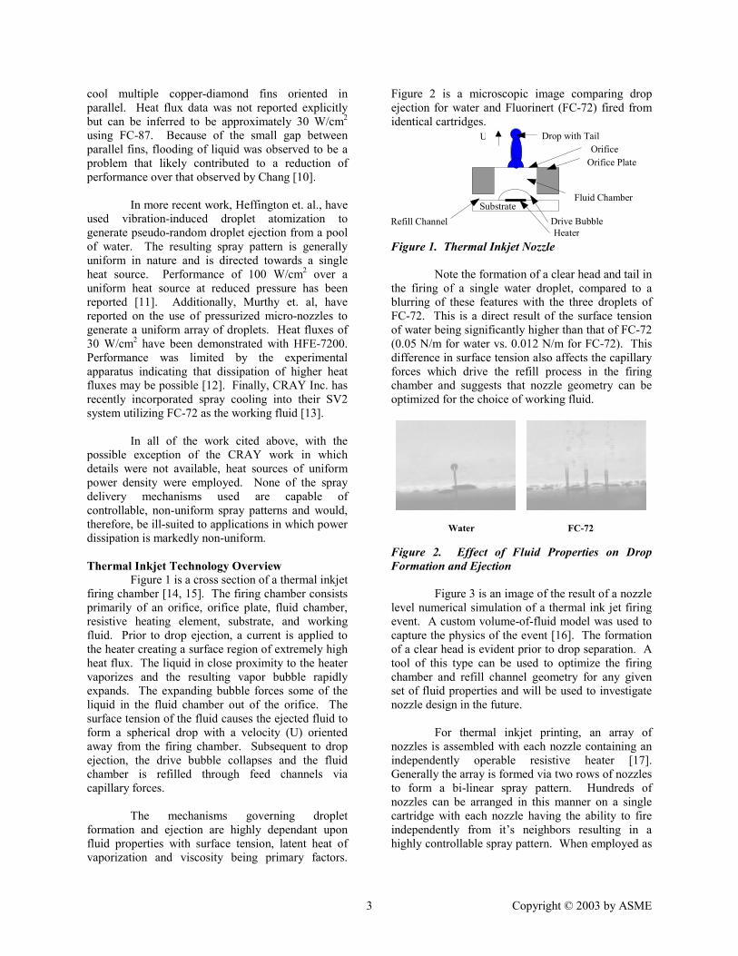
Figure 1 is a cross section of a thermal inkjet firing chamber [14, 15]. The firing chamber consists primarily of an orifice, orifice plate, fluid chamber, resistive heating element, substrate, and working fluid. Prior to drop ejection, a current is applied to the heater creating a surface region of extremely high heat flux. The liquid in close proximity to the heater vaporizes and the resulting vapor bubble rapidly expands. The expanding bubble forces some of the liquid in the fluid chamber out of the orifice. The surface tension of the fluid causes the ejected fluid to form a spherical drop with a velocity (U) oriented away from the firing chamber. Subsequent to drop ejection, the drive bubble collapses and the fluid chamber is refilled through feed channels via capillary forces.
The mechanisms governing droplet
formation and ejection are highly dependant upon fluid properties with surface tension, latent heat of vaporization and viscosity being primary factors.
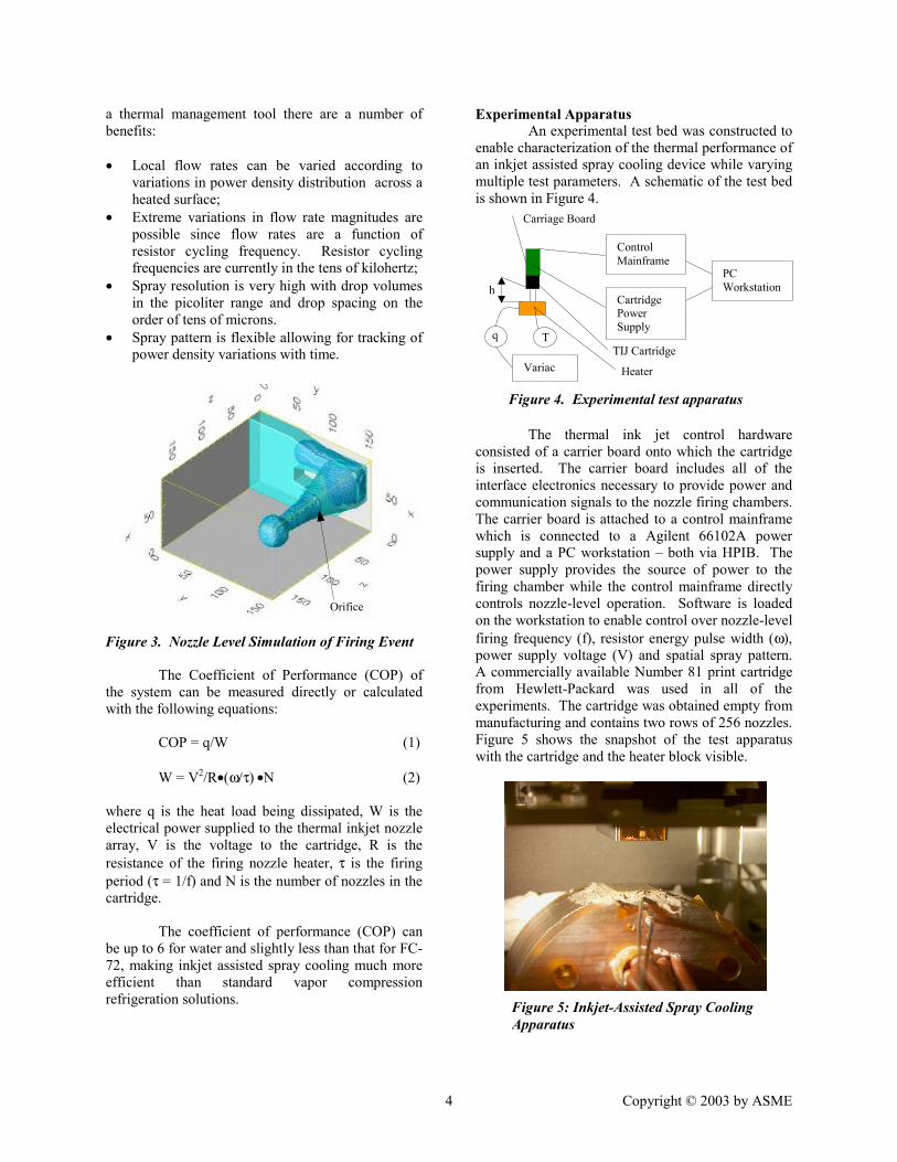
Figure 2 is a microscopic image comparing drop ejection for water and Fluorinert (FC-72) fired from identical cartridges. Figure 1. Thermal Inkjet Nozzle Note the formation of a clear head and tail in the firing of a single water droplet, compared to a blurring of these features with the three droplets of FC-72. This is a direct result of the surface tension of water being significantly higher than that of FC-72 (0.05 N/m for water vs. 0.012 N/m for FC-72). This difference in surface tension also affects the capillary forces which drive the refill process in the firing chamber and suggests that nozzle geometry can be optimized for the choice of working fluid.
Figure 2. Effect of Fluid Properties on Drop Formation and Ejection
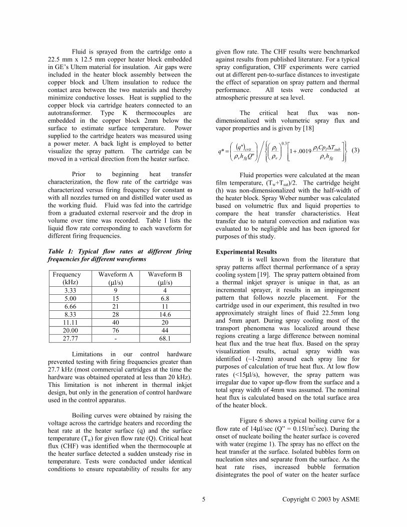
Figure 3 is an image of the result of a nozzle
level numerical simulation of a thermal ink jet firing event. A custom volume-of-fluid model was used to capture the physics of the event [16]. The formation of a clear head is evident prior to drop separation. A tool of this type can be used to optimize the firing chamber and refill channel geometry for any given set of fluid properties and will be used to investigate nozzle design in the future.
For thermal inkjet printing, an array of
nozzles is assembled with each nozzle containing an independently operable resistive heater [17]. Generally the array is formed via two rows of nozzles to form a bi-linear spray pattern. Hundreds of nozzles can be arranged in this manner on a single cartridge with each nozzle having the ability to fire independently from it’s neighbors resulting in a highly controllable spray pattern. When employed as
Water FC-72
Substrate Drive Bubble Heater
Fluid Chamber
Drop with Tail
Orifice Plate Orifice
Refill Channel
U
4 Copyright © 2003 by ASME
a thermal management tool there are a number of benefits: • Local flow rates can be varied according to
variations in power density distribution across a heated surface;
• Extreme variations in flow rate magnitudes are possible since flow rates are a function of resistor cycling frequency. Resistor cycling frequencies are currently in the tens of kilohertz;
• Spray resolution is very high with drop volumes in the picoliter range and drop spacing on the order of tens of microns.
• Spray pattern is flexible allowing for tracking of power density variations with time.
Figure 3. Nozzle Level Simulation of Firing Event
The Coefficient of Performance (COP) of the system can be measured directly or calculated with the following equations: COP = q/W (1) W = V2/R•(ω/τ) •N (2) where q is the heat load being dissipated, W is the electrical power supplied to the thermal inkjet nozzle array, V is the voltage to the cartridge, R is the resistance of the firing nozzle heater, τ is the firing period (τ = 1/f) and N is the number of nozzles in the cartridge.
The coefficient of performance (COP) can
be up to 6 for water and slightly less than that for FC-72, making inkjet assisted spray cooling much more efficient than standard vapor compression refrigeration solutions.
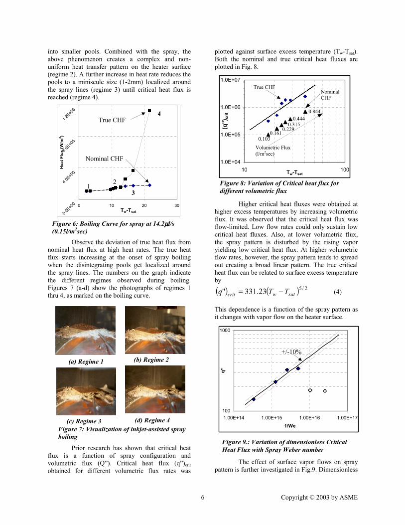
Experimental Apparatus An experimental test bed was constructed to enable characterization of the thermal performance of an inkjet assisted spray cooling device while varying multiple test parameters. A schematic of the test bed is shown in Figure 4.
The thermal ink jet control hardware consisted of a carrier board onto which the cartridge is inserted. The carrier board includes all of the interface electronics necessary to provide power and communication signals to the nozzle firing chambers. The carrier board is attached to a control mainframe which is connected to a Agilent 66102A power supply and a PC workstation – both via HPIB. The power supply provides the source of power to the firing chamber while the control mainframe directly controls nozzle-level operation. Software is loaded on the workstation to enable control over nozzle-level firing frequency (f), resistor energy pulse width (ω), power supply voltage (V) and spatial spray pattern. A commercially available Number 81 print cartridge from Hewlett-Packard was used in all of the experiments. The cartridge was obtained empty from manufacturing and contains two rows of 256 nozzles. Figure 5 shows the snapshot of the test apparatus with the cartridge and the heater block visible.
Q
Control Mainframe
Cartridge Power Supply
PC Workstation
Variac
Carriage Board
TIJ Cartridge T
h
Orifice
q
Figure 5: Inkjet-Assisted Spray Cooling Apparatus
Figure 4. Experimental test apparatus
Heater
5 Copyright © 2003 by ASME
Fluid is sprayed from the cartridge onto a 22.5 mm x 12.5 mm copper heater block embedded in GE’s Ultem material for insulation. Air gaps were included in the heater block assembly between the copper block and Ultem insulation to reduce the contact area between the two materials and thereby minimize conductive losses. Heat is supplied to the copper block via cartridge heaters connected to an autotransformer. Type K thermocouples are embedded in the copper block 2mm below the surface to estimate surface temperature. Power supplied to the cartridge heaters was measured using a power meter. A back light is employed to better visualize the spray pattern. The cartridge can be moved in a vertical direction from the heater surface.
Prior to beginning heat transfer
characterization, the flow rate of the cartridge was characterized versus firing frequency for constant ω with all nozzles turned on and distilled water used as the working fluid. Fluid was fed into the cartridge from a graduated external reservoir and the drop in volume over time was recorded. Table I lists the liquid flow rate corresponding to each waveform for different firing frequencies. Table I: Typical flow rates at different firing frequencies for different waveforms
Frequency (kHz)
Waveform A (µl/s)
Waveform B (µl/s)
3.33 9 4 5.00 15 6.8 6.66 21 11 8.33 28 14.6
11.11 40 20 20.00 76 44 27.77 - 68.1
Limitations in our control hardware
prevented testing with firing frequencies greater than 27.7 kHz (most commercial cartridges at the time the hardware was obtained operated at less than 20 kHz). This limitation is not inherent in thermal inkjet design, but only in the generation of control hardware used in the control apparatus.
Boiling curves were obtained by raising the voltage across the cartridge heaters and recording the heat rate at the heater surface (q) and the surface temperature (Tw) for given flow rate (Q). Critical heat flux (CHF) was identified when the thermocouple at the heater surface detected a sudden unsteady rise in temperature. Tests were conducted under identical conditions to ensure repeatability of results for any
given flow rate. The CHF results were benchmarked against results from published literature. For a typical spray configuration, CHF experiments were carried out at different pen-to-surface distances to investigate the effect of separation on spray pattern and thermal performance. All tests were conducted at atmospheric pressure at sea level.
The critical heat flux was non-dimensionalized with volumetric spray flux and vapor properties and is given by [18]
( )
∆+
=
fgv
subll
v
l
fgv
crith
TCpQh
ρρ
ρρ
ρ0019.1
""
*3.0
(3)
Fluid properties were calculated at the mean
film temperature, (Tw+Tsat)/2. The cartridge height (h) was non-dimensionalized with the half-width of the heater block. Spray Weber number was calculated based on volumetric flux and liquid properties to compare the heat transfer characteristics. Heat transfer due to natural convection and radiation was evaluated to be negligible and has been ignored for purposes of this study. Experimental Results
It is well known from the literature that spray patterns affect thermal performance of a spray cooling system [19]. The spray pattern obtained from a thermal inkjet sprayer is unique in that, as an incremental sprayer, it results in an impingement pattern that follows nozzle placement. For the cartridge used in our experiment, this resulted in two approximately straight lines of fluid 22.5mm long and 5mm apart. During spray cooling most of the transport phenomena was localized around these regions creating a large difference between nominal heat flux and the true heat flux. Based on the spray visualization results, actual spray width was identified (~1-2mm) around each spray line for purposes of calculation of true heat flux. At low flow rates (<15µl/s), however, the spray pattern was irregular due to vapor up-flow from the surface and a total spray width of 4mm was assumed. The nominal heat flux is calculated based on the total surface area of the heater block.
Figure 6 shows a typical boiling curve for a
flow rate of 14µl/sec (Q” = 0.15l/m2sec). During the onset of nucleate boiling the heater surface is covered with water (regime 1). The spray has no effect on the heat transfer at the surface. Isolated bubbles form on nucleation sites and separate from the surface. As the heat rate rises, increased bubble formation disintegrates the pool of water on the heater surface
6 Copyright © 2003 by ASME
into smaller pools. Combined with the spray, the above phenomenon creates a complex and non-uniform heat transfer pattern on the heater surface (regime 2). A further increase in heat rate reduces the pools to a miniscule size (1-2mm) localized around the spray lines (regime 3) until critical heat flux is reached (regime 4).
Observe the deviation of true heat flux from
nominal heat flux at high heat rates. The true heat flux starts increasing at the onset of spray boiling when the disintegrating pools get localized around the spray lines. The numbers on the graph indicate the different regimes observed during boiling. Figures 7 (a-d) show the photographs of regimes 1 thru 4, as marked on the boiling curve.
Prior research has shown that critical heat flux is a function of spray configuration and volumetric flux (Q”). Critical heat flux (q”)crit obtained for different volumetric flux rates was
plotted against surface excess temperature (Tw-Tsat). Both the nominal and true critical heat fluxes are plotted in Fig. 8.
Higher critical heat fluxes were obtained at
higher excess temperatures by increasing volumetric flux. It was observed that the critical heat flux was flow-limited. Low flow rates could only sustain low critical heat fluxes. Also, at lower volumetric flux, the spray pattern is disturbed by the rising vapor yielding low critical heat flux. At higher volumetric flow rates, however, the spray pattern tends to spread out creating a broad linear pattern. The true critical heat flux can be related to surface excess temperature by
( ) ( ) 2/523.331" satwcrit TTq −= (4) This dependence is a function of the spray pattern as it changes with vapor flow on the heater surface.
The effect of surface vapor flows on spray
pattern is further investigated in Fig.9. Dimensionless
0.0E+0
0
4.0E+0
5
8.0E+0
5
1.2E+0
6
0 10 20 30Tw-Tsat
Hea
t Flu
x (W
/m2 )
Figure 6: Boiling Curve for spray at 14.2µµµµl/s (0.15l/m2sec)
True CHF
Nominal CHF
12
3
4
(a) Regime 1
(c) Regime 3 (d) Regime 4
(b) Regime 2
Figure 7: Visualization of inkjet-assisted spray boiling
100
1000
1.00E+14 1.00E+15 1.00E+16 1.00E+171/We
q*
Figure 9.: Variation of dimensionless Critical Heat Flux with Spray Weber number
+/-10%
1.0E+04
1.0E+05
1.0E+06
1.0E+07
10 100Tw-Tsat
(q")
crit
True CHF Nominal CHF
0.1030.161
0.229 0.315
0.444 0.844
Volumetric Flux (l/m2sec)
Figure 8: Variation of Critical heat flux for different volumetric flux
7 Copyright © 2003 by ASME
CHF obtained for different volumetric flow rates are plotted against the inverse of the corresponding Weber number. The results are benchmarked with spray cooling results obtained by Mudawar and Estes [18]. The dimensionless CHF for flow rates above 15µl/sec (0.16l/m2sec) follows the Weber number dependence introduced by Mudawar and Estes within an error of 10%. The relationship is given by
35.0* 001187.0 −= Weq (5)
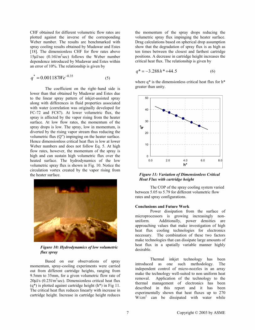
The coefficient on the right–hand side is lower than that obtained by Mudawar and Estes due to the linear spray pattern of inkjet-assisted spray along with differences in fluid properties associated with water (correlation was originally developed for FC-72 and FC87). At lower volumetric flux, the spray is affected by the vapor rising from the heater surface. At low flow rates, the momentum of the spray drops is low. The spray, low in momentum, is diverted by the rising vapor stream thus reducing the volumetric flux (Q”) impinging on the heater surface. Hence dimensionless critical heat flux is low at lower Weber numbers and does not follow Eq. 5. At high flow rates, however, the momentum of the spray is high and can sustain high volumetric flux over the heated surface. The hydrodynamics of the low volumetric spray flux is shown in Fig. 10. Notice the circulation vortex created by the vapor rising from the heater surface.
Based on our observations of spray
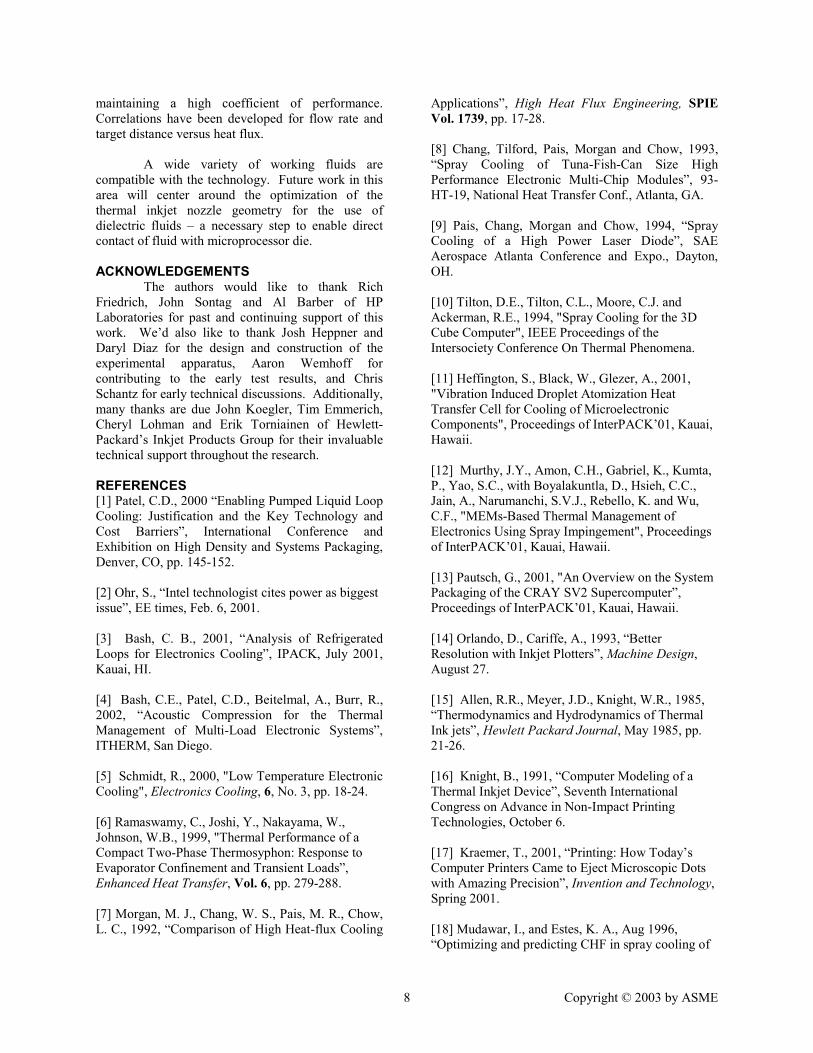
momentum, spray-cooling experiments were carried out from different cartridge heights, ranging from 9.5mm to 35mm, for a given volumetric flow rate of 20µl/s (0.23l/m2sec). Dimensionless critical heat flux (q*) is plotted against cartridge height (h*) in Fig 11. The critical heat flux reduces linearly with increase in cartridge height. Increase in cartridge height reduces
the momentum of the spray drops reducing the volumetric spray flux impinging the heater surface. Drag calculations based on spherical drop assumption show that the degradation of spray flux is as high as ten times between the closest and farthest cartridge positions. A decrease in cartridge height increases the critical heat flux. The relationship is given by
5.44*288.3* +−= hq (6) where q* is the dimensionless critical heat flux for h* greater than unity.
The COP of the spray cooling system varied
between 5.05 to 5.79 for different volumetric flow rates and spray configurations. Conclusions and Future Work Power dissipation from the surface of microprocessors is growing increasingly non-uniform. Additionally, power densities are approaching values that make investigation of high heat flux cooling technologies for electronics necessary. The combination of these two factors make technologies that can dissipate large amounts of heat flux in a spatially variable manner highly desirable. Thermal inkjet technology has been introduced as one such methodology. The independent control of micro-nozzles in an array make the technology well-suited to non uniform heat removal. Application of the technology to the thermal management of electronics has been described in this report and it has been experimentally shown that heat fluxes up to 270 W/cm2 can be dissipated with water while
0
10
20
30
40
50
0.0 2.0 4.0 6.0 8.0h*
q*
Figure 11: Variation of Dimensionless Critical Heat Flux with cartridge height
Figure 10: Hydrodynamics of low volumetric flux spray
8 Copyright © 2003 by ASME
maintaining a high coefficient of performance. Correlations have been developed for flow rate and target distance versus heat flux. A wide variety of working fluids are compatible with the technology. Future work in this area will center around the optimization of the thermal inkjet nozzle geometry for the use of dielectric fluids – a necessary step to enable direct contact of fluid with microprocessor die. ACKNOWLEDGEMENTS
The authors would like to thank Rich Friedrich, John Sontag and Al Barber of HP Laboratories for past and continuing support of this work. We’d also like to thank Josh Heppner and Daryl Diaz for the design and construction of the experimental apparatus, Aaron Wemhoff for contributing to the early test results, and Chris Schantz for early technical discussions. Additionally, many thanks are due John Koegler, Tim Emmerich, Cheryl Lohman and Erik Torniainen of Hewlett-Packard’s Inkjet Products Group for their invaluable technical support throughout the research.
REFERENCES [1] Patel, C.D., 2000 “Enabling Pumped Liquid Loop Cooling: Justification and the Key Technology and Cost Barriers”, International Conference and Exhibition on High Density and Systems Packaging, Denver, CO, pp. 145-152. [2] Ohr, S., “Intel technologist cites power as biggest issue”, EE times, Feb. 6, 2001. [3] Bash, C. B., 2001, “Analysis of Refrigerated Loops for Electronics Cooling”, IPACK, July 2001, Kauai, HI. [4] Bash, C.E., Patel, C.D., Beitelmal, A., Burr, R., 2002, “Acoustic Compression for the Thermal Management of Multi-Load Electronic Systems”, ITHERM, San Diego. [5] Schmidt, R., 2000, "Low Temperature Electronic Cooling", Electronics Cooling, 6, No. 3, pp. 18-24. [6] Ramaswamy, C., Joshi, Y., Nakayama, W., Johnson, W.B., 1999, "Thermal Performance of a Compact Two-Phase Thermosyphon: Response to Evaporator Confinement and Transient Loads”, Enhanced Heat Transfer, Vol. 6, pp. 279-288. [7] Morgan, M. J., Chang, W. S., Pais, M. R., Chow, L. C., 1992, “Comparison of High Heat-flux Cooling
Applications”, High Heat Flux Engineering, SPIE Vol. 1739, pp. 17-28. [8] Chang, Tilford, Pais, Morgan and Chow, 1993, “Spray Cooling of Tuna-Fish-Can Size High Performance Electronic Multi-Chip Modules”, 93-HT-19, National Heat Transfer Conf., Atlanta, GA. [9] Pais, Chang, Morgan and Chow, 1994, “Spray Cooling of a High Power Laser Diode”, SAE Aerospace Atlanta Conference and Expo., Dayton, OH. [10] Tilton, D.E., Tilton, C.L., Moore, C.J. and Ackerman, R.E., 1994, "Spray Cooling for the 3D Cube Computer", IEEE Proceedings of the Intersociety Conference On Thermal Phenomena. [11] Heffington, S., Black, W., Glezer, A., 2001, "Vibration Induced Droplet Atomization Heat Transfer Cell for Cooling of Microelectronic Components", Proceedings of InterPACK’01, Kauai, Hawaii. [12] Murthy, J.Y., Amon, C.H., Gabriel, K., Kumta, P., Yao, S.C., with Boyalakuntla, D., Hsieh, C.C., Jain, A., Narumanchi, S.V.J., Rebello, K. and Wu, C.F., "MEMs-Based Thermal Management of Electronics Using Spray Impingement", Proceedings of InterPACK’01, Kauai, Hawaii. [13] Pautsch, G., 2001, "An Overview on the System Packaging of the CRAY SV2 Supercomputer”, Proceedings of InterPACK’01, Kauai, Hawaii. [14] Orlando, D., Cariffe, A., 1993, “Better Resolution with Inkjet Plotters”, Machine Design, August 27. [15] Allen, R.R., Meyer, J.D., Knight, W.R., 1985, “Thermodynamics and Hydrodynamics of Thermal Ink jets”, Hewlett Packard Journal, May 1985, pp. 21-26. [16] Knight, B., 1991, “Computer Modeling of a Thermal Inkjet Device”, Seventh International Congress on Advance in Non-Impact Printing Technologies, October 6. [17] Kraemer, T., 2001, “Printing: How Today’s Computer Printers Came to Eject Microscopic Dots with Amazing Precision”, Invention and Technology, Spring 2001. [18] Mudawar, I., and Estes, K. A., Aug 1996, “Optimizing and predicting CHF in spray cooling of

9 Copyright © 2003 by ASME
a square surface”, ASME J. Heat Transfer, Vol. 118, pp672-679. [19] Sembehey, M.S., Chow, L. C., Pais, M.R., and Mahefkey, T., 1995, “High Heat Flux spray cooling of Electronics”, Trans. Am. Inst. Physics, pp903-909.