Embed Size (px)
Citation preview
Injection Molding of Thermoplastics
OVERVIEW
Injection molding is a major processing tech- nique for converting thermoplastic materials, accounting for almost 20% of U.S. resin pro- duction.
The process was patented by John and Isaiah Hyatt in 1872 to mold camphor-plasticized cel- lulose nitrate (celluloid). The first multicavity mold was introduced by John Hyatt in 1878. Modem technology began to develop in the late 1930s and was accelerated by the demands of World War 11. A similar surge in the technol- ogy of materials and equipment took place in the late sixties and early seventies.
This section will discuss the machinery and the practice of injection molding.
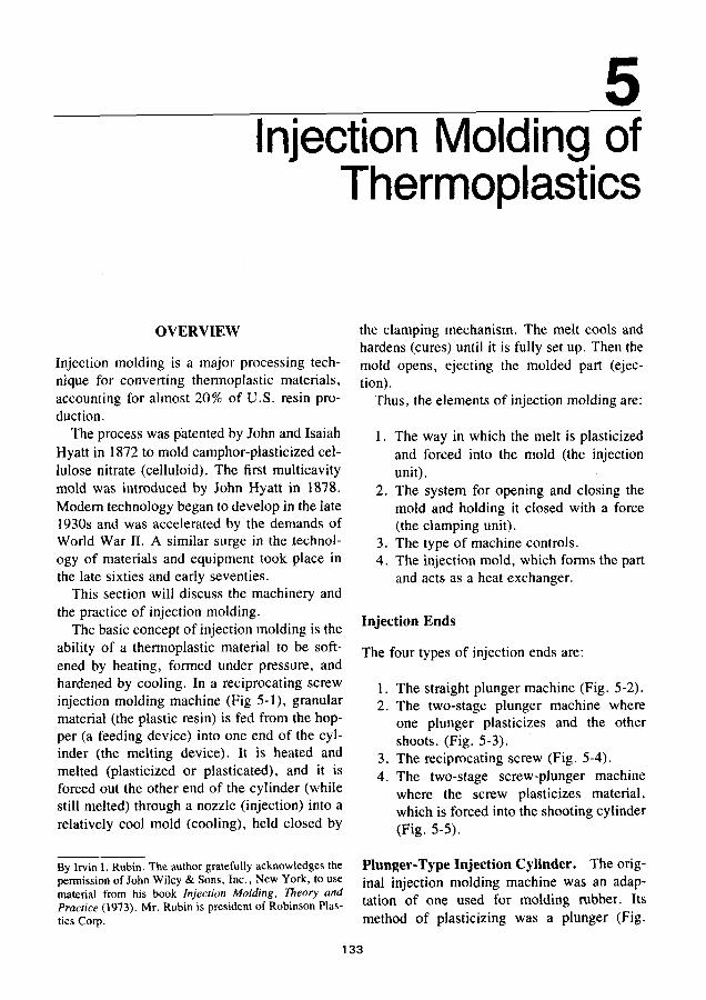
The basic concept of injection molding is the ability of a thermoplastic material to be soft- ened by heating, formed under pressure, and hardened by cooling. In a reciprocating screw injection molding machine (Fig 5- l), granular material (the plastic resin) is fed from the hop- per (a feeding device) into one end of the cyl- inder (the melting device). It is heated and melted (plasticized or plasticated), and it is forced out the other end of the cylinder (while still melted) through a nozzle (injection) into a relatively cool mold (cooling), held closed by
By Irvin I. Rubin. The author gratefully acknowledges the permission of John Wiley & Sons, Inc., New York, to use material from his book Injection Molding, Theory and Practice (1973). Mr. Rubin is president of Robinson Plas- tics Cop.
the clamping mechanism. The melt cools and hardens (cures) until it is fully set up. Then the mold opens, ejecting the molded part (ejec- tion).
Thus, the elements of injection molding are:
1. The way in which the melt is plasticized and forced into the mold (the injection unit).
2. The system for opening and closing the mold and holding it closed with a force (the clamping unit).
3. The type of machine controls. 4. The injection mold, which forms the part
and acts as a heat exchanger.
Injection Ends
The four types of injection ends are:
1. The straight plunger machine (Fig. 5-2). 2. The two-stage plunger machine where
one plunger plasticizes and the other shoots. (Fig. 5-3).
3. The reciprocating screw (Fig. 5-4). 4. The two-stage screw-plunger machine
where the screw plasticizes material, which is forced into the shooting cylinder (Fig. 5-5) .
Plunger-Type Injection Cylinder. The orig- inal injection molding machine was an adap- tation of one used for molding rubber. Its method of plasticizing was a plunger (Fig.
133
134 SPI PLASTICS ENGINEERING HANDBOOK
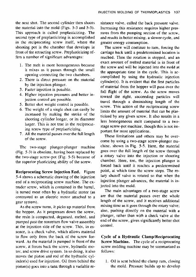
3 Fig. 5-1. Reciprocating screw injection molding machine with a 300-ton hydraulic clamp and a 28-02 injection shot capacity. (Courtesy HPM Corp.)
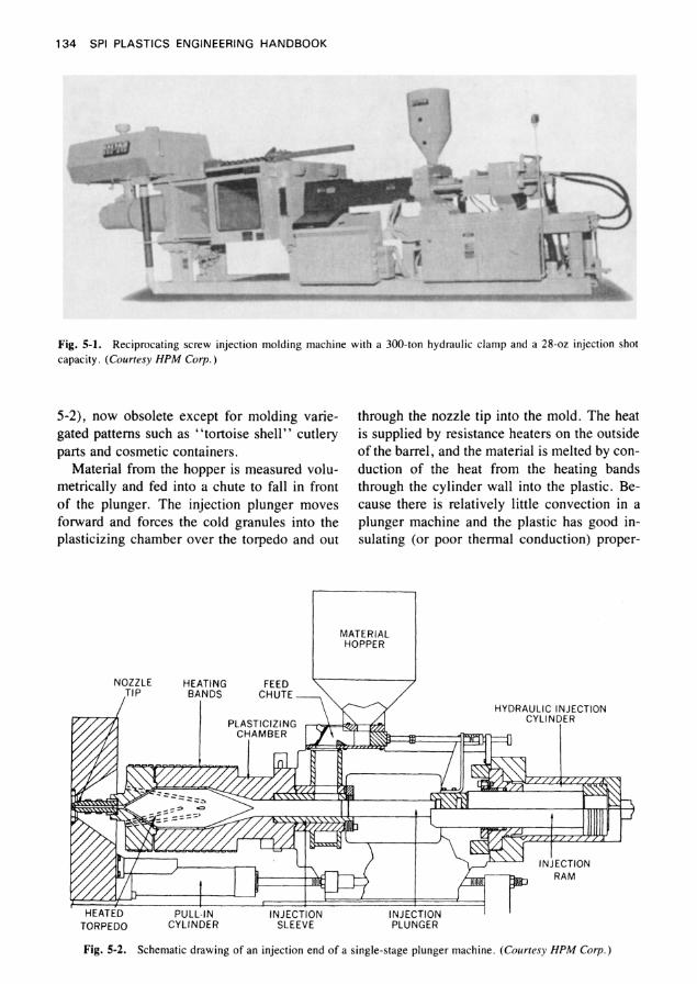
5-2), now obsolete except for molding varie- gated patterns such as “tortoise shell” cutlery parts and cosmetic containers.
Material from the hopper is measured volu- metrically and fed into a chute to fall in front of the plunger. The injection plunger moves forward and forces the cold granules into the plasticizing chamber over the torpedo and out
through the nozzle tip into the mold. The heat is supplied by resistance heaters on the outside of the barrel, and the material is melted by con- duction of the heat from the heating bands through the cylinder wall into the plastic. Be- cause there is relatively little convection in a plunger machine and the plastic has good in- sulating (or poor thermal conduction) proper-
MATERIAL HOPPER
NOZZLE HEATING FEED ,TIP BANDS CHUTE -
HYDRAULIC INJECTION PLASTICIZING
HEATED P U L L ~ N INJECTION INJECTION CYLINDER SLEEVE PLUNGER TORPEDO
Fig. 5-2. Schematic drawing of an injection end of a single-stage plunger machine. (Courtesy H P M Corp.)
INJECTION MOLDING OF THERMOPLASTICS 135
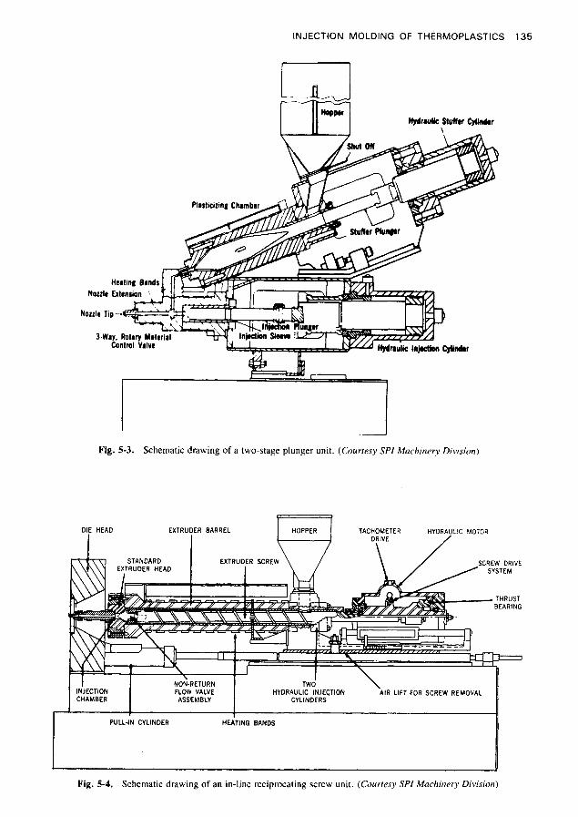
Fig. 5-3. Schematic drawing of a two-stage plunger unit. (Courresy SPI Machinery Division)
NON-RETURN INJECTION FLOW VALVE HYDRAULIC INJECTION AIR LIFT FOR SCREW REMOVAL CHAMBER ASSEMBLY CYLINDERS
1 I I PULL-IN CYLINDER HEATING BANDS
~.
Fig. 5-4. Schematic drawing of an in-line reciprocating screw unit. (Courtesy SPI Machinery Division)
136 SPI PLASTICS ENGINEERING HANDBOOK
ROTARY ADMISSION EXTRUDER EXTRUDER SHUT.OFF VALVE BARREL SCREW
VAl VF / I I FEED CHUTE
MATERIAL HOPPER
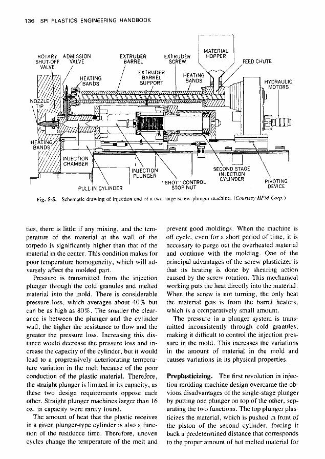
Fig. 5-5. Schematic drawing of injection end of a two-stage screw-plunger machme. (CourrPsy HPM Corp. )
ties, there is little if any mixing, and the tem- perature of the material at the wall of the torpedo is significantly higher than that of the material in the center. This condition makes for poor temperature homogeneity, which will ad- versely affect the molded part.
Pressure is transmitted from the injection plunger through the cold granules and melted material into the mold. There is considerable pressure loss, which averages about 40% but can be as high as 80 % . The smaller the clear- ance is between the plunger and the cylinder wall, the higher the resistance to flow and the greater the pressure loss. Increasing this dis- tance would decrease the pressure loss and in- crease the capacity of the cylinder, but it would lead to a progressively deteriorating tempera- ture variation in the melt because of the poor conduction of the plastic material. Therefore, the straight plunger is limited in its capacity, as these two design requirements oppose each other. Straight plunger machines larger than 16 oz. in capacity were rarely found.
The amount of heat that the plastic receives in a given plunger-type cylinder is also a func- tion of the residence time. Therefore, uneven cycles change the temperature of the melt and
prevent good moldings. When the machine is off cycle, even for a short period of time, it is necessary to purge out the overheated material and continue with the molding. One of the principal advantages of the screw plasticizer is that its heating is done by shearing action caused by the screw rotation. This mechanical working puts the heat directly into the material. When the screw is not turning, the only heat the material gets is from the barrel heaters, which is a comparatively small amount.
The pressure in a plunger system is trans- mitted inconsistently through cold granules, making it difficult to control the injection pres- sure in the mold. This increases the variations in the amount of material in the mold and causes variations in its physical properties.
Preplasticizing. The first revolution in injec- tion molding machine design overcame the ob- vious disadvantages of the single-stage plunger by putting one plunger on top of the other, sep- arating the two functions. The top plunger plas- ticizes the material, which is pushed in front of the piston of the second cylinder, forcing it back a predetermined distance that corresponds to the proper amount of hot melted material for
INJECTION MOLDING OF THERMOPLASTICS 137
the next shot. The second cylinder then shoots the material into the mold (Figs. 5-3 and 5-5) . This approach is called preplasticizing. The second type of preplasticizing is accomplished in the reciprocating screw itself, where the shooting pot is the chamber that develops in front of the retracting screw. Preplasticizing of- fers a number of significant advantages:
1.
2.
3 . 4.
5 . 6 .
7.
The melt is more homogeneous because it mixes as it passes through the small opening connecting the two chambers. There is direct pressure on the material by the injection plunger. Faster injection is possible. Higher injection pressures and better in- jection control are possible. Better shot weight control is possible. The weight of a single shot can easily be increased by making the stroke of the shooting cylinder longer, or its diameter larger. This is not true in the reciprocat- ing screw type of preplasticizing. All the material passes over the full length of the screw.
The two-stage plunger-plunger machine (Fig. 5-3) is obsolete, having been replaced by the two-stage screw-pot (Fig. 5-5) because of the superior plasticizing ability of the screw.
Reciprocating Screw Injection End. Figure 5-4 shows a schematic drawing of the injection end of a reciprocating screw machine. The ex- truder screw, which is contained in the barrel, is turned most often by a hydraulic motor (as contrasted to an electric motor attached to a gear system).
As the screw turns, it picks up material from the hopper. As it progresses down the screw, the resin is compacted, degassed, melted, and pumped past the nonreturn flow valve assembly at the injection side of the screw. This, in es- sence, is a check valve, which allows material to flow only from the back of the screw for- ward. As the material is pumped in front of the screw, it forces back the screw, hydraulic mo- tor, and screw drive system. In so doing, it also moves the piston and rod of the hydraulic cyl- inder(s) used for injection. Oil from behind the piston(s) goes into a tank through a variable re-
sistance valve, called the back pressure valve. Increasing this resistance requires higher pres- sures from the pumping section of the screw, and results in better mixing, a slower cycle, and greater energy consumption.
The screw will continue to turn, forcing the camage back until a predetermined location is reached. Then the rotation is stopped, and an exact amount of melted material is in front of the screw and will be injected into the mold at the appropriate time in the cycle. This is ac- complished by using the hydraulic injection cylinder(s). It is evident that the first particles of material from the hopper will pass over the full flight of the screw. As the screw moves toward the right, succeeding particles will travel through a diminishing length of the screw. This action of the reciprocating screw limits the amount of material that can be plas- ticized by any given screw. It also results in a less homogeneous melt compared to a two- stage screw-pot machine, though this is not im- portant for most applications.
These limitations and others may be over- come by using a two-stage screw-plunger ma- chine, shown in Fig. 5-5. Here, the material goes over the full length of the screw through a rotary valve into the injection or shooting chamber. Here, too, the injection plunger is forced back until it reaches a predetermined point, at which time the screw stops. The ro- tary shutoff valve is rotated so that when the injection plunger advances, the material is in- jected into the mold.
The main advantages of a two-stage screw are that the material passes over the whole length of the screw, and it receives additional mixing time as it goes through the rotary valve; also, pushing directly on the material with a plunger, rather than with a check valve at the end of the screw, gives significantly better shot control.
Cycle of a Hydraulic Clamp/Reciprocating Screw Machine. The cycle of a reciprocating screw molding machine may be summarized as follows:
1. Oil is sent behind the clamp ram, closing the mold. Pressure builds up to develop
SPI PLASTICS ENGINEERING HANDBOOK 138
2
3.
4.
5 .
6.
7 .
enough force to keep the mold closed while the injection process occurs. Previously plasticized material in front of the reciprocating screw is forced into the mold by the hydraulic injection cylin- der(s). Pressure is maintained on the material to mold a part free of sink marks, flow marks, welds, and other defects. At the end of this period, the screw starts to turn, plasticizing material for the next shot. After melting, the material is de- compressed to prevent drooling from the nozzle. While this is occumng, the plastic is cooling in the mold and solidifying to a point where it can be successfully ejected. This cooling is accomplished by circulat- ing a cooling medium, usually water, through drilled holes or channels in cav- ities, cores, and the mold base. Oil is sent to the return port of the clamp- ing ram separating the mold halves. As the moving platen returns, the knock- out or ejection mechanism is activated, removing the pieces from the mold.
Packing. Once the mold is filled initially, ad- ditional material is added to the mold by the injection pressure to compensate for thermal shrinkage as the material cools. This process is called packing. Too much packing will result in highly stressed parts and may cause ejection problems. Insufficient packing causes short shots, poor surface, sink marks, welds, and other defects. The proper amount of packing is determined by trial and error or with the as- sistance of computerized process simulation. The material will continue to flow into the mold as long as there is injection pressure, provided that the gate is not sealed. When no more ma- terial enters the mold, contraction of the cool- ing material results in a rapid decrease in the pressure in the mold. The residual pressure caused by the original deformation of the steel of the mold and the adhesion of the plastic to the steel must be overcome by the knockout system to eject the parts.
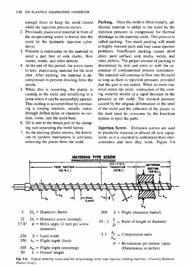
Injection Screw. Extrusion screws are used to plasticize material in almost all new equip- ment, so it is essential to understand their char- acteristics and how they work. Figure 5-6
METERING TYPE SCREW
X D, =
2; D, = 17.8" 6 =
.250 S =
.350 h, =
.IO5 h , = 50 L =
Diameter-Barrel .005 6 =
2 0 : l - = Diameter screw (normal) L Helix angle (1 turn per screw diameter)
Land width Flight depth (feed)
Flight depth (metering) Overall length
D
h h M
3.3 2 =
N =
D B Flight clearance (radial)
Ratio of length to diameter
Compression ratio
Revolutions per minute (rpm) (Dimensions in inches)
Fig. 5-6. Plastics Corp.)
Typical metering screw used for reciprocating screw type injection molding machines. (Courtesy Robinson
INJECTION MOLDING OF THERMOPLASTICS 139
shows a typical screw used in injection mold- ing equipment. Its task is to convey the cold pellets at the hopper end, compact and degas the material in the feed section, plasticize it in the transition section, pump the screw back in the metering section, and act as a plunger forc- ing the material into the mold.
The feed section is approximately half the length of the screw, the melting or transition section one-quarter the length, and the meter- ing or pumping section one-quarter the length. The outside diameter of the barrel is deter- mined by the pressure requirements of the cyl- inder. An extruder barrel requires a pressure that generally does not exceed 8000 psi, whereas the barrel of a reciprocating screw must contain at least the 20,000 psi of injection pressure that is developed. The diameter of the screw is the nominal diameter of the hole in the barrel. Experience has shown that a pitch of one turn per screw diameter works well for in- jection molding. This helix angle (e) is 17.8", which is standard for injection screws. The land width is approximately 10% of the diameter. The radial flight clearance is specified by con- sidering the effects of leakage flow over the flights, the temperature increase in the plastics caused by this clearance, the scraping ability of the flights in cleaning the barrel, the eccentric- ity of the screw and barrel, and the manufac- turing costs. The depth of the flight is constant but different in the feed and metering sections; it is reduced from the deeper feed section to the shallower metering section in the transition section wherein the material is melted. The compression ratio of a screw is the ratio of the flight depth in the feed section to that in the metering section. The length of the screw is the axial length of the flighted section. The ratio of the length to the diameter ( L / D ) is a very im- portant specification in a screw. Higher L I D ratios give a more uniform melt, better mixing, and higher output pressures. An L I D of 20 : 1 should be the minimum for molding machines, with higher ratios such as 24 : 1 more desira- ble. For more information on extruder design in general, refer to Chapter 4.
Melting a Plastic in a Screw
To be conveyed forward, the plastic must ad-
coefficients of friction between the plastic and the screw and between the plastic and the barrel were identical, there would be no flow of ma- terial-it would just rotate as a plug within the flight of the screw. Because the polymer mol- ecule is anchored more to the side of the barrel than to the screw, the polymer molecules slide over one another. This behavior is called a shearing action. In effect, molecular forces are being broken and turned into heat; this is what is meant when one refers to converting the me- chanical action of the screw into heat.
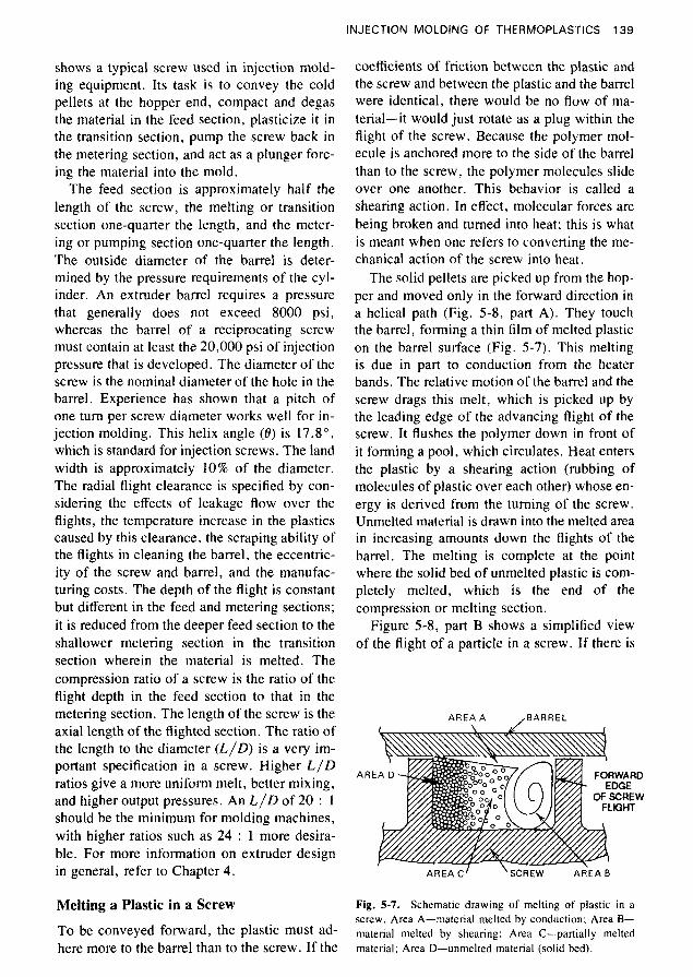
The solid pellets are picked up from the hop- per and moved only in the forward direction in a helical path (Fig. 5-8, part A). They touch the barrel, forming a thin film of melted plastic on the barrel surface (Fig. 5-7). This melting is due in part to conduction from the heater bands. The relative motion of the barrel and the screw drags this melt, which is picked up by the leading edge of the advancing flight of the screw. It flushes the polymer down in front of it forming a pool, which circulates. Heat enters the plastic by a shearing action (rubbing of molecules of plastic over each other) whose en- ergy is derived from the turning of the screw. Unmelted material is drawn into the melted area in increasing amounts down the flights of the barrel. The melting is complete at the point where the solid bed of unmelted plastic is com- pletely melted, which is the end of the compression or melting section.
Figure 5-8, part B shows a simplified view of the flight of a particle in a screw. If there is
AREA A ,BARREL
ARE
AREA CI 'SCREW A R E A B
Fig. 5-7. Schematic drawing of melting of plastic in a screw. Area A-material melted by conduction; Area B- material melted by shearing; Area C-partially melted
here more to the barrel than to the screw. If the material; Area D-unmelted material (solid bed).
140 SPI PLASTICS ENGINEERING HANDBOOK
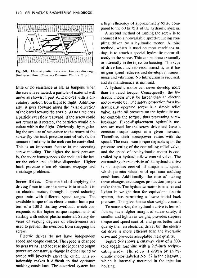
Fig. 5-8. Flow of plastic in a screw. A-open discharge. B-blocked flow. (Courtesy Robinson Plastics Corp. )
little or no resistance at all, as happens when the screw is retracted, a particle of material will move as shown in part A. It moves with a cir- culatory motion from flight to flight. Addition- ally, it goes forward along the axial direction of the barrel toward the nozzle. At no time does a particle ever flow rearward. If the screw could not retract as it rotated, the particles would cir- culate within the flight. Obviously, by regulat- ing the amount of resistance to the return of the screw (by the back pressure control valve), the amount of mixing in the melt can be controlled. This is an important feature in reciprocating screw molding. The higher the back pressure is, the more homogeneous the melt and the bet- ter the color and additive dispersion. Higher back pressure often eliminates warpage and shrinkage problems.
Screw Drives. One method of applying the driving force to turn the screw is to attach it to an electric motor, through a speed-reducing gear train with different speed ranges. The available torque of an electric motor has a pat- tern of a 100% starting overload, which cor- responds to the higher torque requirements of starting with colder plastic material. Safety de- vices of varying degrees of effectiveness are used to prevent the overload from snapping the
Electric drives do not have independent speed and torque control. The speed is changed by gear trains, and because the input and output power are constant, a change in either speed or torque will inversely affect the other. This re- lationship makes it difficult to find optimum molding conditions. The electrical system has
screw.
a high efficiency of approximately 9 5 % , com- pared to the 60 to 75 % of the hydraulic system.
A second method of turning the screw is to connect it to a nonvariable speed-reducing cou- pling driven by a hydraulic motor. A third method, which is used on most machines to- day, is to attach a special hydraulic motor di- rectly to the screw. This can be done externally or internally in the injection housing. This type of drive has much to recommend it, as it has no gear speed reducers and develops minimum noise and vibration. No lubrication is required, and its maintenance is minimal.
A hydraulic motor can never develop more than its rated torque. Consequently, the hy- draulic motor must be larger than an electric motor would be. The safety protection for a hy- draulically operated screw is a simple relief valve, as the oil pressure on the hydraulic mo- tor controls the torque, thus preventing screw breakage. Fixed-displacement hydraulic mo- tors are used for the screw drive and have a constant torque output at a given pressure. Therefore, their horsepower varies with the speed. The maximum torque depends upon the pressure setting of the controlling relief valve, and the speed of the hydraulic motor is con- trolled by a hydraulic flow control valve. The outstanding characteristic of the hydraulic drive is its stepless control of torque and speed, which permits selection of optimum molding conditions. Additionally, the ease of making these changes encourages production people to make them. The hydraulic motor is smaller and lighter in weight than the equivalent electric system, thus permitting a lower initial back pressure. This gives better shot weight control.
To summarize, the hydraulic drive is less ef- ficient, has a higher margin of screw safety, it smaller and lighter in weight, provides stepless torque and speed control, and gives better melt quality than an electrical drive; but the electri- cal drive is more efficient than the hydraulic drive and provides acceptable melt quality.
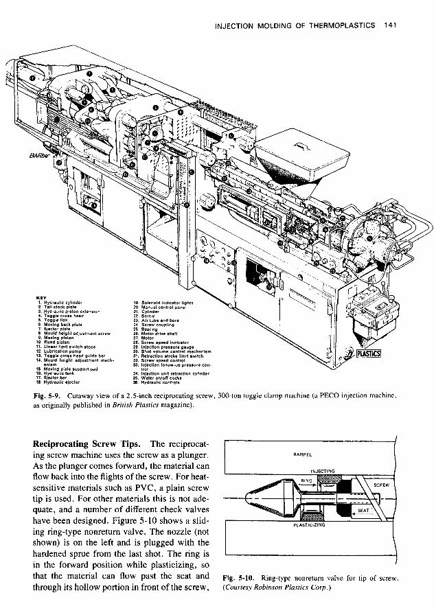
Figure 5-9 shows a cutaway view of a 300- tone toggle machine with a 2.5-inch recipro- cating screw. The screw is driven by an hy- draulic motor (labeled No. 27 in the diagram), which is internally mounted in the injection housing.
INJECTION MOLDING OF THERMOPLASTICS 141
Fig. 5-9. as originally published in British Plastics magazine).
Cutaway view of a 2.5-inch reciprocating screw, 300-ton toggle clamp machine (a PECO injection machine,
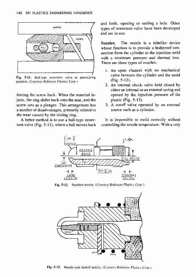
Reciprocating Screw Tips. The reciprocat-
As the plunger comes forward, the material can flow back into the flights of the screw. For heat- sensitive materials such as PVC, a plain screw tip is used. For other materials this is not ade- quate, and a number of different check valves have been designed. Figure 5-10 shows a slid- ing ring-type nonreturn valve. The nozzle (not shown) is on the left and is plugged with the hardened sprue from the last shot. The ring is
that the material can flow past the seat and through its hollow portion in front of the screw,
ing screw machine uses the screw as a plunger. BARREL
in the forward position while plasticizing, so I
Fig. 5-10. Ring-type nonreturn valve for tip of screw. (Courtesy Robinson Plastics carp.)
142 SPI PLASTICS ENGINEERING HANDBOOK
BARREL
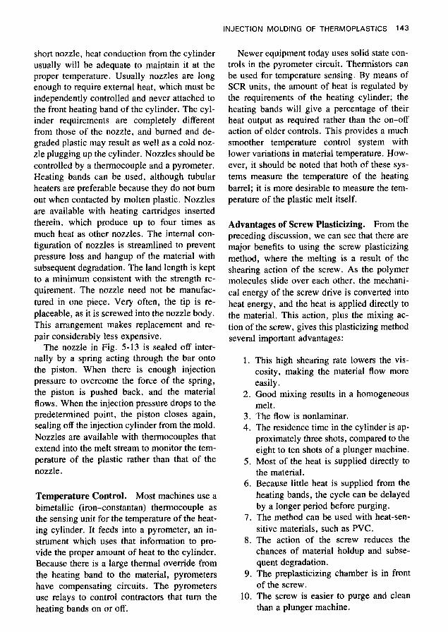
I / Fig. 5-11. Ball-type nonretum valve in plasticizing position. (Courtesy Robinson Plastics Corp.)
forcing the screw back. When the material in- jects, the ring slides back onto the seat, and the screw acts as a plunger. This arrangement has a number of disadvantages, primarily related to the wear caused by the sliding ring.
A better method is to use a ball-type nonre- turn valve (Fig. 5-1 I ) , where a ball moves back
and forth, opening or sealing a hole. Other types of nonreturn valve have been developed and are in use.
Nozzles. The nozzle is a tubelike device whose function is to provide a leakproof con- nection from the cylinder to the injection mold with a minimum pressure and thermal loss. There are three types of nozzles:
1.
2.
3.
An open channel with no mechanical valve between the cylinder and the mold (Fig. 5-12). An internal check valve held closed by either an internal or an external spring and opened by the injection pressure of the plastic (Fig. 5-13). A cutoff valve operated by an external source such as a cylinder.
It is impossible to mold correctly without controlling the nozzle temperature. With a very
dt- L A N D
. LENGTH -
Fig. 5-12. Standard nozzle. (Courtesy Robinson Plastics Corp.)
Fig. 5-13. Needle-type shutoff nozzle. (Courtesy Robinsoiz Plastics Corp.)
INJECTION MOLDING OF THERMOPLASTICS 143
short nozzle, heat conduction from the cylinder usually will be adequate to maintain it at the proper temperature. Usually nozzles are long enough to require external heat, which must be independently controlled and never attached to the front heating band of the cylinder. The cyl- inder requirements are completely different from those of the nozzle, and burned and de- graded plastic may result as well as a cold noz- zle plugging up the cylinder. Nozzles should be controlled by a thermocouple and a pyrometer. Heating bands can be used, although tubular heaters are preferable because they do not bum out when contacted by molten plastic. Nozzles are available with heating cartridges inserted therein, which produce up to four times as much heat as other nozzles. The internal con- figuration of nozzles is streamlined to prevent pressure loss and hangup of the material with subsequent degradation. The land length is kept to a minimum consistent with the strength re- quirement. The nozzle need not be manufac- tured in one piece. Very often, the tip is re- placeable, as it is screwed into the nozzle body. This arrangement makes replacement and re- pair considerably less expensive.
The nozzle in Fig. 5-13 is sealed off inter- nally by a spring acting through the bar onto the piston. When there is enough injection pressure to overcome the force of the spring, the piston is pushed back, and the material flows. When the injection pressure drops to the predetermined point, the piston closes again, sealing off the injection cylinder from the mold. Nozzles are available with thermocouples that extend into the melt stream to monitor the tem- perature of the plastic rather than that of the nozzle.
Temperature Control. Most machines use a bimetallic (iron-constantan) thermocouple as the sensing unit for the temperature of the heat- ing cylinder. It feeds into a pyrometer, an in- strument which uses that information to pro- vide the proper amount of heat to the cylinder. Because there is a large thermal override from the heating band to the material, pyrometers have compensating circuits. The pyrometers use relays to control contractors that turn the heating bands on or off.
Newer equipment today uses solid state con- trols in the pyrometer circuit. Thermistors can be used for temperature sensing. By means of SCR units, the amount of heat is regulated by the requirements of the heating cylinder; the heating bands will give a percentage of their heat output as required rather than the on-off action of older controls. This provides a much smoother temperature control system with lower variations in material temperature. How- ever, it should be noted that both of these sys- tems measure the temperature of the heating barrel; it is more desirable to measure the tem- perature of the plastic melt itself.
Advantages of Screw Plasticizing. From the preceding discussion, we can see that there are major benefits to using the screw plasticizing method, where the melting is a result of the shearing action of the screw. As the polymer molecules slide over each other, the mechani- cal energy of the screw drive is converted into heat energy, and the heat is applied directly to the material. This action, plus the mixing ac- tion of the screw, gives this plasticizing method several important advantages:
1. This high shearing rate lowers the vis- cosity, making the material flow more easily.
2. Good mixing results in a homogeneous melt.
3. The flow is nonlaminar. 4. The residence time in the cylinder is ap-
proximately three shots, compared to the eight to ten shots of a plunger machine.
5. Most of the heat is supplied directly to the material.
6. Because little heat is supplied from the heating bands, the cycle can be delayed by a longer period before purging.
7. The method can be used with heat-sen- sitive materials, such as PVC.
8. The action of the screw reduces the chances of material holdup and subse- quent degradation.
9. The preplasticizing chamber is in front of the screw.
10. The screw is easier to purge and clean than a plunger machine.
144 SPI PLASTICS ENGINEERING HANDBOOK
Injection End Specifications. The following items must be specified:
1. Type-reciprocating screw or screw-pot. 2. Diameter of the screw. 3. L/D ratio. 4. Maximum weight in ounces of polysty-
rene that can be injected in one shot; or, alternatively, the volume of material per shot.
5. The plasticizing capacity, which is in ef- fect the amount of material that can be melted per unit time with the screw run- ning continuously. In injection molding the screw runs about one-half of the time.
6. Maximum injection pressure on the screw, usually 20,000 psi.
7. Other specifications that will be provided by the manufacturer and are dictated by the above.
Clamping Ends of Injection Molding Machines
The clamping and injection ends of a molding machine are described and rated separately. All clamp ends use hydraulic force. Machines can be completely hydraulic, a combination of a hydraulic cylinder and a toggle mechanism, or completely electric. Clamp ends are rated by the maximum number of tons of locking force exerted. In a fully hydraulic machine the rela- tionship is:
P X A 2000
F = -
where:
F = force (tons) P = pressure (lb/in.2) A = area of clamp ram (in.2)
ample, a center-gated polystyrene box 10 x 14 inches or 140 sq. in. would require a 350-ton press (140 in.2 X 2.5 tons/in.2 = 350 tons). The depth of the box would not be relevant in determining the clamp force requirements be- cause the sides are not perpendicular to the clamping force.
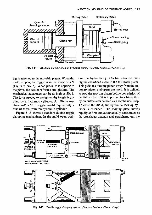
Hydraulic Clamping System. Figure 5- 14 shows a schematic drawing of a hydraulic clamping system. The stationary platen is at- tached to the molding machine and has four tie rods that go through it and support the moving platen and then go through the hydraulic mounting plate. At each end of the tie rods are tie rod nuts. The hydraulic clamp ram moves the moving platen, to which is attached the moving or knockout side of the mold. The sta- tionary side of the mold is attached to the sta- tionary platen. The ejection mechanism of the molding machine is not shown.
As can be seen from Fig. 5-14, when oil is put in the forward port, the clamp ram will move the moving platen until the mold parts make contact. As the pressure builds up, the force behind the clamp ram is transmitted through it, the moving platen, the mold, and the stationary platen to the tie rod nuts. This force stretches the tie bar, which provides the clamping action. When the mold is to be opened, oil is sent to the return port, and the forward port is vented to the tank. This retracts the clamp ram, the moving platen, and the moving part of the mold. The plastic part nor- mally remains on the moving part of the mold and is ejected or knocked out of the mold by the ejection mechanism (see below). The ejec- tion mechanism can be operated mechanically or hydraulically, with the latter means prefer- able because it allows for control of the timing, direction, and force of the stroke. In a mechan- ical system the knockout plate is stopped by the knockout bars of the machine.
As a rule of thumb, 2; tons of force is re- quired for each square inch of projected area of whatever is molded. The projected area is the maximum area parallel to the clamping force (Le., the platens). A part behind another part does not require extra clamping force. For ex-
Toggle Systems. Another type of clamp is the toggle, which is a mechanical device used to amplify force. In a molding machine, it con- sists of two bars joined together end to end with a pivot. The end of one bar is attached to a stationary platen, and the other end of a second
INJECTION MOLDING OF THERMOPLASTICS 145
Moving platen Stationary platen
Fig; 5-14. Schematic drawing of an all-hydraulic clamp. (Courtesy Robinson Plastics Corp.)
bar is attached to the movable platen. When the mold is open, the toggle is in the shape of a V (Fig. 5-9, No. 5). When pressure is applied to the pivot, the two bars form a straight line. The mechanical advantage can be as high as 50 : 1. The force needed to straighten the toggle is ap- plied by a hydraulic cylinder. A 350-ton ma- chine with a 50 : l toggle would require only 7 tons of force from the hydraulic cylinder.
Figure 5-15 shows a standard double toggle clamping mechanism. In the mold open posi-
tion, the hydraulic cylinder has retracted, pull- ing the crosshead close to the tail stock platen. This pulls the moving platen away from the sta- tionary platen and opens the mold. It is difficult to stop the moving platen before completion of the full stroke. If it is important to achieve this, nylon buffers can be used as a mechanical stop. To close the mold, the hydraulic locking cyl- inder is extended. The moving plate moves rapidly at first and automatically decelerates as the crosshead extends and straightens out the
MOL0 HEIGHT AOJUSTMENT LOWNUTS DRIVEN 8Y CHAIN
NUT
Fig. 5-15. Double toggle clamping system. (Courtesy Robinson PIusrics Corp.)
146 SPI PLASTICS ENGINEERING HANDBOOK
links. A small motion of the crosshead devel- ops a large mechanical advantage, causing the locking.
The two main advantages of a toggle system are the economy of running a much smaller hy- draulic cylinder rather than a comparable fully hydraulic machine and the speed of the design per dollar of cost. Fully hydraulic clamps are capable of moving as fast as toggles, but the cost to achieve this is higher than that of an equivalent toggle system. Another advantage of the toggle system is that it is self-locking. Once the links have reached their extended position, they will remain there until retracted. The hy- draulic system requires continuous mainte- nance of line pressure.
The toggle systems on molding machines have several disadvantages. A primary one is that there is no indication of the clamping force, so that it is difficult to adjust and monitor. The clamping force in a hydraulic system is read immediately by a pressure gauge and can be controlled in stepless increments, but in a tog- gle press it must be read with a strain gauge on a tie bar. As the room temperature changes, so does the length of the tie bar, thus changing the
LOCKING MECHANISM
clamping force. The only way to control toggle clamp pressure as well as that of a hydraulic clamp is to use a computer-controlled machine with feedback. It is difficult to control the speed and force of the toggle mechanism, as well as starting and stopping at different points. A ma- jor disadvantage of the toggle system is that it requires significantly more maintenance than a hydraulic one; it is susceptible to much more wear.
In order to clamp properly, the toggles must be fully extended. Therefore, the distance of the tail stock platen has to be changed to ac- commodate different molds. This is done with a chain or gears that simultaneously move the four locking nuts on the tail stock platen. It can be turned mechanically, electrically, or hy- draulically.
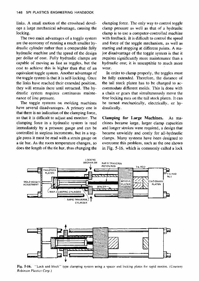
Clamping for Large Machines. As ma- chines became large, larger clamp capacities and longer strokes were required, a design that became unwieldy and costly for all-hydraulic clamps. Many systems have been designed to overcome this problem, such as the one shown in Fig. 5-16, which is commonly called a lock
RAPID TRAVERSE
OD
MOLD HEIGHT ADJUSTMENT
CYLINDER
Fig. 5-16. Robinson Plastics Corp.)
“Lock and block” type clamping system using a spacer and locking plates for rapid motion. (Courresy
INJECTION MOLDING OF THERMOPLASTICS 147
and block. A small-diameter high-speed rapid traverse cylinder is used to move the movable platen. Spacers, which may be hollow tubes, are attached to the movable platen and main clamping cylinder. At the end of the stroke of the rapid traverse cylinder, a locking mecha- nism, hydraulically operated, is inserted be- tween the spacers. The large-diameter short- stroke hydraulic cylinder moves forward ap- proximately an inch to provide the full locking force. This type of lock and block mechanism requires a mold height adjustment. Systems of this design, while losing a slight speed advan- tage because of the three motions, gain in econ- omy because they have a smaller hydraulic cyl- inder size, lower power requirements, and no need for huge toggle links.
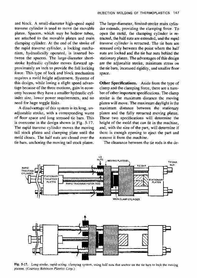
A disadvantage of this system is its long, un- adjustable stroke, with a corresponding waste of floor space and long stressed tie bars. This is overcome in the design shown in Fig. 5-17. The rapid traverse cylinder moves the moving tail stock platen and clamping plate until the mold closes. The half nuts are closed over the tie bars, anchoring the moving tail stock platen.
The large-diameter, limited-stroke main cylin- der extends, providing the clamping force. To open the mold, the clamping cylinder is re- tracted, the half nuts are extended, and the rapid traverse cylinder is retracted. The tie bars are stressed only between the point where the half nuts are locked and the tie bar nuts behind the stationary platen. The advantages of this design are the adjustable stroke, minimum stress on the tie bars, increased rigidity, and smaller floor space.
Other Specifications. Aside from the type of clamp and the clamping force, there are a num- ber of other important specifications. The clamp stroke is the maximum distance the moving platen will move. The maximum daylight is the maximum distance between the stationary platen and the fully retracted moving platen. These two specifications will determine the height of the mold that can fit in the machine, and, with the size of the part, will determine if there is enough opening to eject the part and remove it from the machine.
The clearance between the tie rods is the de-
112 '"7 (MOVING PLATENS, TIE BAA
MAiN CLAMPCYLINDER . I
Fig. 5-17. Long-stroke, rapid-acting, damping system, using half nuts that anchor on the tie bars to lock the moving platens. (Courtesy Robinson Plastics Corp.)
148 SPI PLASTICS ENGINEERING HANDBOOK
termining factor for whether a mold of a given length or width will fit into the press. The length and width dimensions of the molds are often determined by the side that is parallel to the knockout plate.
The clamp speed is an important specifica- tion. Losing a half second per shot on a ma- chine producing 100 shots per hour will waste 110 productive hours a year.
The knockout stroke determines the maxi- mum knockout movement available. There are two types of knockout system-a mechanical one that stops the knockout plate before the mold stops and a hydraulic one that is indepen- dent of the machine action. The hydraulic knockout system is preferable.
Machine knockout patterns all follow the SPI standard so that molds are interchangeable among machines. The other specifications are determined by the manufacturer to achieve the desired results.
Circuits
Space does not permit discussing electrical and hydraulic circuits. Older machines used elec- tro-mechanical relays and timers. The newer machines are using solid state devices, which are more reliable. Monitoring of the injection speed, melt temperature, pressure, and pres- sure of the material in the mold forms the basis for the automatic control of the injection mold- ing process. This is done in computer-con- trolled machines with feedback. There are ma- chines with computers that lack this capability; but they, like those with feedback, provide use- ful information for the molder, such as setting molding conditions, keeping track of machine performance, giving real-time warning of trou- bles, and providing statistical quality control. Machines with feedback have increased in ef- ficiency to the point where they are rapidly re- placing nonfeedback machines. This is the third “revolution” in injection molding machines, the other two being preplasticizing and the re- ciprocating screw. (For details, see the section on “Process Control” at the end of this chap- ter.)
Automation
The expression “automatic machines” often is used in referring to automatic molding. This is a misnomer, as all machines today are auto- matic. The basis for automatic molding is the mold, and there are a number of requirements for the process. The machine must be capable of constant repetitive action, the mold must clear itself automatically, and low-pressure closing must be available so that any stuck parts will not damage the mold.
Automatic molding does not necessarily eliminate the operator. Many times an operator is present to package the parts and perform sec- ondary operations. Automatic molding gives a better-quality piece at a more rapid cycle. Usu- ally when automatic molding machines are used, an experienced person attends several machines. Unless the powder, feed, and part removal are automated, he or she will take care of them.
Automation is expensive to obtain. It re- quires excellent machinery, molds, trained em- ployees, and managerial skills. When the quan- tity of parts permits, it is a satisfactory and economical method of operation.
The use of robots in both part and sprue/run- ner removal from machines and assembly has led to fully automatic plants. In the late 1980s, about 80% of the Japanese molding machines were equipped with robots, compared to 12% in the United States. This situation is rapidly changing, and the concept of total automation has begun to be evident in U.S. plants.
Materials Handling
Plastic materials are shipped in 25-pound tins, 50-pound bags, 300-pound drums, 1000-pound Gaylords, tank trucks, and tank cars. In the lat- ter two instances, they. are pneumatically re- moved into silos for storage. From there they are conveyed automatically to the molding ma- chine.
The selection of the proper materials han- dling technique can greatly reduce wastage caused by contamination and spillage. Regard- less of the size of the plant, the materials han-
INJECTION MOLDING OF THERMOPLASTICS 149
dling procedure should be constantly reviewed and updated. The subject is covered in Chapter 21.
Sprues, runners, and rejected parts can be re- ground and reused. A typical grinder consists of an electric motor that turns a shaft on which there are blades that cut the plastic. The re- ground material usually is blended with virgin material, a step that can be done automatically.
Certain materials such as nylon, polycarbon- ate, and cellulose acetate are hygroscopic, or moisture-absorbing. They must be dried by heating, as moisture causes surface defects and seriously degrades the material. Drying can be done in ovens that are thermostatically con- trolled and circulate heated air. The material is spread out in trays for drying. Alternatively, hopper driers fit on top of the molding machine and send filtered, heated, dried air through the material to dry it.
A third method is to use a vented extruder barrel. In this method the material is com- pressed, melted, and then decompressed under a vent. The material is at about 400”F, well above the boiling point of water. The steam usually escapes by itself; if not, a vacuum is used. The material then is recompressed and pumped in front of the screw.
Secondary Operations
Injection-molded parts are fabricated and dec- orated with the same techniques used on plas- tics manufactured by other methods. Milling off gates, drilling, and routing are routinely done on molded parts. Frequently the cycle time al- lows these operations to be done at the press. Cementing, ultrasonic and vibratory welding, riveting, eyeletting , tapping, and adding me- tallic threaded inserts and nuts and bolts are common methods of joining plastic to itself or to other materials.
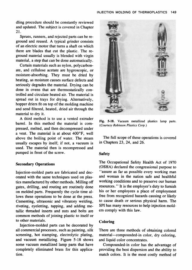
Injection-molded parts can be decorated by all commercial processes, such as painting, silk screening, hot stamping, electrolytic plating, and vacuum metallizing. Figure 5-18 shows some vacuum metallized lamp parts that have completely eliminated brass for this applica- tion.
Fig. 5-18. Vacuum metallized plastics lamp parts. (Courtesy Robinson Plastics Corp.)
The full scope of these operations is covered in Chapters 23, 24, and 26.
Safety
The Occupational Safety Health Act of 1970 (OSHA) declared the congressional purpose to “assure as far as possible every working man and woman in the nation safe and healthful working conditions and to preserve our human resources.” It is the employer’s duty to furnish his or her employees a place of employment free. from recognized hazards causing or likely to cause death or serious physical harm. The SPI has many resources to help injection mold- ers comply with this law.
Coloring
There are three methods of obtaining colored material-compounded-in color, dry coloring, and liquid color concentrates.
Compounded-in color has the advantage of providing the best dispersion and the ability to match colors. It is the most costly method of
150 SPI PLASTICS ENGINEERING HANDBOOK
coloring, requiring a large inventory compared with other methods and a significantly longer lead time for production. The base material is reextruded with colorants.
Dry coloring consists of tumbling the basic resin with a colorant, and sometimes wetting agents are used. It requires a minimum inven- tory of the uncolored material. Dry colorants usually are packed in bags for mixing with 50, 100, or 200 pounds of the resin. It has a num- ber of disadvantages: The wrong colorant might be used, or the colorant might not be com- pletely emptied into the tumbling equipment. There is a lot of materials handling and a chance for loss. It is basically a messy procedure, and, because of the dusting, may cause contamina- tion problems. It is more difficult to clean the feed system with this method. Colors that re- quire several pigments, particularly in small amounts, are very difficult to color evenly. Dis- persion can be significantly poorer than in com- pounded material, and in many instances is un- acceptable.
A compromise between compounded-in ma- terial and dry coloring is to use color concen- trates or masterbatches. High concentrations of colorant are extruded into the same resin from which the parts will be molded. The concen- trate usually is prepared so that 5 pounds of concentrate will color 100 pounds of base resin. Although this method is more expensive than dry coloring, it overcomes a number of that method’s disadvantages. Colors difficult to match in dry coloring usually will work with color concentrates., Compared to compounded- in materials, these colorants usually are less ex- pensive, require lower material inventory, and occupy less space.
Also, liquid color concentrates can be used with automatic material handling systems, which meter in liquid colorant during feeding. This is an economical means of coloring.
Coloring methods are covered in more detail in Chapter 22.
Multicylinder Machines
Machines are built with two or more cylinders to mold two different colors of the same mate- rial or two different materials. (Buttons on tele-
phones, calculators, and computers are good examples of the applications of the process.) The mold design is different from the single- cylinder type in that two-shot molding requires a tool with two identical cores and two different cavities. The core side of the mold is able to rotate. To mold a two-shot button, for exam- ple, one core/cavity would mold the base in the primary color or material from the first cylin- der, leaving an air space for the letter or sym- bol desired. The mold would rotate 180”, and the second cavity would seal off the first mold- ing, which has an air space for the letter or symbol. The second color or material would be molded into it from the second cylinder. While this is happening, the first set would be mold- ing the first color.
Two cylinders also can be used for sandwich molding, to combine functional materials (in the core) and “appearance” materials for the surface.
THEORY OF INJECTION MOLDING
This section will develop a qualititative theory of injection molding based on rheological data, concepts of energy levels, molecular structure and forces, and theories of heat transfer. This theory can be of great value in preventing prob- lems, solving difficulties, and providing an understanding of the literature. Of necessity, coverage of this kind will contain certain gen- eralizations, which, while not mathematically exact, adequately serve the purpose.
The reasons why a quantitative statement of injection molding is impossible become clear when one analyzes the machinery, materials, and process. The factors that affect the pro- cess-material temperature, temperature pro- file, pressure, material velocities in the cylin- der and mold, mold temperature, viscosity, and flow patterns-are not measured at all or are measured intermittently at isolated points. Un- til recent years there was no feedback of the processing variables to the molding machine to compensate automatically for changing condi- tions.
The material used is not identical each time, having different heat histories, molecular
INJECTION MOLDING OF THERMOPLASTICS 151
weights, molecular weight distributions, de- grees of polymerization, and impurities. It is exposed to moist air and compressed with it in the heating cylinder, with varying amounts of oxidation. It is heated by convection, conduc- tion, and shearing. The pressure changes, from zero to possibly 30,000 psi.
The material is not linear in most of its func- tions. It is compressible, stretchable, elastic, and subject to changing properties after re- moval from the mold. It may differ according to the direction of the material flow in the mold. It has time-dependent properties that are strongly altered by its environment. In some materials, there are varying degrees of crystal- linity, which are not reproducible or predict- able. For these reasons, quantitative solutions are not yet possible. This is equally true of computer-generated information.
Material exists in three forms-solid, liquid, and gas. In plastics, one is concerned primarily with the liquid and solid phases. In crystalline materials, the change from solid to liquid is ab- rupt and easily discernible. In an amorphous (noncrystalline) polymer, the change is not ab- rupt or readily apparent; the material softens over a wide temperature range, and there is no dramatic visible change in its properties at any given point, such as would be found in the con- version of ice to water or water to ice. If certain properties of an amorphous plastic such as the specific volume or heat capacity are plotted against the temperature, at a certain point there is an abrupt change of the slope of the line. In the thermodynamic sense, this is called a sec- ond-order transition; in polymer science, it is called the glass transition point (Tg) . Below the glass transition point the polymer is stiff and dimensionally stable, behaving like a solid. It has brittle characteristics with little elasticity, and its properties are relatively time-indepen- dent. Above Tg the polymer will behave as a viscous liquid, being elastomeric and having highly time-dependent properties.
The difference between the three forms of matter can be explained in terms of molecular attraction. In a solid, the closeness of the mol- ecules to each other permits the strong cohesive force of molecular attraction to limit their mo- tion relative to each other. Although solids can
be deformed, it takes a comparatively large amount of energy to do so. If the solid is stressed below its elastic limit, it will be de- formed. An ideal solid obeys Hooke’s law, which states that the amount of strain (move- ment) is directly proportional to the stress (force). The constant of proportionality, E (stress/strain), is called Young’s modulus or the modulus of elasticity. When the stress is re- moved, the molecular bonds that have been stretched contract, bringing the solid back to its original position. Plastics are not ideal solids; they exhibit, in common with all other mate- rials, elastic properties that are combined with viscous or flow properties. Hence, they are called viscoelastic materials.
When a stress is applied to a polymer above its Tgr the initial movement is elastic, of a Hookean type. It represents stretching the chemical bonds. As more stress is applied, the plastic molecules slide over each other. This is viscous flow, which is not recoverable. There is a third type of flow, which is a retarded type of elasticity. When the stress is removed, the initial elastic deformation is instantaneously re- covered, a response that is Hookean in nature. The retarded elasticity eventually will recover, but not instantaneously; the length of time will depend on the nature of the material.
There are two energy systems within a ma- terial. One is the potential energy of Newtonian gravitational energy, and is a measure of the forces between the molecules. The other is ki- netic energy, which is the energy of motion and is related to the thermal or heat energy of the system; it is the random motion of the mole- cules, called Brownian movement. The higher the internal (heat) energy of the system is, the greater the random motion.
In a solid, the potential energy (forces of at- traction between the molecules) is larger than the kinetic energy (energy of movement tend- ing to separate the molecules). Hence, a solid has an ordered structure, with a molecular at- traction strong enough to limit the molecules’ motion relative to each other.
As more energy is put into the system, it turns into a liquid where the potential and the kinetic energy are equal. The molecules can move relative to each other, but the cohesive
152 SPI PLASTICS ENGINEERING HANDBOOK
forces are large enough to maintain a molecu- larly contiguous medium.
It is appropriate here to briefly review the nature of the bonding forces in the polymer. The two major bonding forces in plastics are the covalent bond and the secondary forces, called van der Waals forces. The atom consists of a relatively small nucleus that contains most of the atom’s mass and the positive charges, and negative electrons that spin around the nu- cleus. The orbits of the electrons form outer concentric shells, each of which has certain sta- ble configurations. A covalent bond exists when the electron in the outer shells of two atoms is shared between them. This is typical of car- bon-carbon bonds and is the primary bond found in polymers used commercially. It has a disassociation energy of 83 kcal/mole.
The van der Waals forces are electrostatic in nature and have a disassociation energy of 2 to 5 kcal/mole. These forces exist between mol- ecules and molecular segments, and they vary as the sixth power of the distance. Obviously much weaker than the primary covalent bond, they are part of the resistance to flow. The en- ergy that attracts molecules, as contrasted to the bonds holding atoms together, is sometimes called cohesive energy, and it is that energy re- quired to move a molecule a large distance from its neighbor.
If one takes a cubic inch of plastic and raises its temperature, its volume will increase. As no molecules are being added to the cube, it is rea- sonable to believe that the distance between the molecules increases. Because the van der Waals forces decrease with the sixth power of the dis- tance, the molecules and their segments be- come much more mobile. As these forces are decreasing in an exponential manner, there is a relatively narrow range in which the polymer properties change from “solid” to a “liq- uid”-the glass transition point (Tg). These co- hesive forces form a major portion of the strength of the polymer; so polymer properties are quite temperature-dependent.
Having a physical concept of a plastic mol- ecule makes it easier to understand its flow properties and characteristics. For example, let us consider the polyethylene polymer, which is made by linking ethylene molecules. The dou-
ble bond between the carbons in ethylene is less stable than the single bond in polyethylene. It is possible, with appropriate temperatures, pressures, and catalysts, to cause the ethylene molecules to react with each to form polyeth- ylene:
(p) - H H n
H H I 1
-c-c- I 1
H H
-c-c- 1 I 1 ) n - l
Ethylene Polyethylene
The molecular weight of an ethylene mole- cule is 32. A typical Ziegler-type polyethylene polymer might have 7000 ethylene molecules with a molecular weight of approximately 200,000. The polymerization does not proceed as simply as indicated above. The polymer molecules will not all be the same length, nor will they polymerize in a straight line of carbon linkages. Also, references to the molecular weight of polymers mean the average molecu- lar weight. The molecular weight distribution is an important characteristic of the polymer. If it is spread over a wide range, its properties will differ from those of a polymer with a nar- row distribution. For example, a wide-spec- trum material shows more elastic effects and extreme pressure sensitivity. The viscosity, solubility, and stress crack resistance are among the other properties affected.
To get some idea of the size of a polyethyl- ene molecule, consider that if the methyl group, CH2, were 0.25 inch in diameter, a typical polyethylene molecule would be one city block long. A molecule of water would be about the size of the methyl group. In view of the pos- sibilities of entanglement, kinking, and partial crystallization of the huge polyethylene mole- cule, compared to the small size and simplicity of the water molecule., it would not be unex- pected to find considerable differences in flow properties between these molecules. The flow of water is relatively simple (Newtonian), whereas the viscoelastic flow of polymers is much more complicated and has not yet been mathematically defined in a quantitative man- ner.