Embed Size (px)
Citation preview

Introduction
ii • GE Plastics Processing Guide
CYCOLAC® resin CYC-400CYCOLOY® resin CYL-425ENDURAN™ resin END-200GELOY® resin GEG-200LEXAN® resin CDC-500NORYL® resin CDX-811NORYL GTX® resin CDX-200SUPEC® resin SUP-300ULTEM® resin ULT-210VALOX® resin VAL-151XENOY® resin X-106Custom Engineered Products CEP-200
Call 1-800-845-0600 for all literature requests.
© Copyright 1998 General Electric Company® and ™ are Registered Trademarks and Trademarks of General Electric Company
Mold DesignMold Materials . . . . . . . . . . . . . . . . . . .1-3Prototype Tooling . . . . . . . . . . . . . . . . .1-6Sprues and Runners . . . . . . . . . . . . . .1-7Gating . . . . . . . . . . . . . . . . . . . . . . . . .1-13Tolerances . . . . . . . . . . . . . . . . . . . . . .1-18Shrinkage . . . . . . . . . . . . . . . . . . . . . .1-18Cavity Venting . . . . . . . . . . . . . . . . . . .1-19Mold Temperature Control . . . . . . . .1-20Draft . . . . . . . . . . . . . . . . . . . . . . . . . . .1-23Part Ejection . . . . . . . . . . . . . . . . . . . .1-24
ProcessingEquipment . . . . . . . . . . . . . . . . . . . . . . .2-3Drying . . . . . . . . . . . . . . . . . . . . . . . . . .2-5Molding Conditions . . . . . . . . . . . . . . .2-9
Troubleshooting TipsProblems/Possible Solutions . . . . . . .3-3Suggested Do’s and Don’ts . . . . . . . . .3-7
About This Injection Molding Processing GuideThis injection molding guide contains general injection moldingparameters that apply to all GE engineering thermoplastic resins.
Available on request are separate product sections with processinginformation specific to each GE resin family as listed below.

Introduction
GE Processing Guide • iii
Injection Molding GEThermoplasticsNew dimensions in processing latitude, adaptability to existingequipment, economics and desirable end-product characteristicsare presented to the injection molder of GE Plastics resins inthis processing guide. Consistent in composition and quality,dependable across a wide range of industrial conditions, GEthermoplastic materials incorporate the flexibility, feasibilityand assurance processors required to meet the sophisticationand selectivity in marketplaces today.
GE resins have outstanding processing characteristics and manywere especially designed for injection molding. However, theseresins – like all thermoplastic materials – are not indestructibleand must be processed appropriately. This is especially truewith GE Plastics flame-retardant resins which have excellentprocessing characteristics, require proper temperature controlwithin the latitudes specific for each grade. It is important thatmachinery, processing parameters and molds be utilized underconditions which give sufficient temperature control, minimiz-ing shear heat, material hang-up and resistance to flow.
GE Plastics’ resins are converted into final parts by a meltprocess. Generally this is the injection molding process where a plastic melt is injected at high pressures into a precisionmold. In addition to this being a high pressure process, it isalso a high temperature process. GE Plastics resins can beprocessed at temperatures ranging from 425˚F (CYCOLAC®
resin) to 800˚F (ULTEM® resin). Proper molding practices forGE Plastics resins must be employed to prevent excessive product degradation.
Introduction
iv • GE Plastics Processing Guide
This Injection Molding Processing Guide is offered as an informational service to customers of GE engineering plasticsand users of products made from these plastics. While GE hasused reasonable efforts to provide accurate information in thispublication, GE expressly disclaims any liability for damages,costs or losses resulting from reliance on the contents of thisInjection Molding Processing Guide. It is the responsibility ofthe product manufacturer to determine the suitability of anydesign or product for its intended purpose.
The standards and specifications discussed in this InjectionMolding Processing Guide are complex and subject to revision.The general information contained in this publication is anoverview only and is not intended to substitute careful andindependent examination of applicable standards and specifications. Adequate end-use environmental testing of finished parts must always be conducted.

GE Plastics
GE Engineering ThermoplasticsInjection Molding Processing Guide
Mol
d D
esig
nIn
ject
ion
Mol
ding
Contents
1-2 • Mold Design
Mold DesignMold Materials . . . . . . . . . . . . . . . . . . . . . . . . . . . . . . . .1-3
P-20 Steel . . . . . . . . . . . . . . . . . . . . . . . . . . . . . . . . . . .1-3H-13 and S-7 Steels . . . . . . . . . . . . . . . . . . . . . . . . . .1-4Corrosion Protection . . . . . . . . . . . . . . . . . . . . . . . . .1-4
Prototype Tooling . . . . . . . . . . . . . . . . . . . . . . . . . . . . . .1-6Conventional Machining Practices . . . . . . . . . . . . .1-6Casting Process . . . . . . . . . . . . . . . . . . . . . . . . . . . . .1-6Liquid Plating Process . . . . . . . . . . . . . . . . . . . . . . . .1-6Flame Spraying . . . . . . . . . . . . . . . . . . . . . . . . . . . . . .1-6Mold Filling Pressure . . . . . . . . . . . . . . . . . . . . . . . . .1-7Computerized Mold Filling Analysis . . . . . . . . . . . . .1-7
Sprues and Runners . . . . . . . . . . . . . . . . . . . . . . . . . . .1-7Cold Sprues . . . . . . . . . . . . . . . . . . . . . . . . . . . . . . . . .1-7Cold Runners . . . . . . . . . . . . . . . . . . . . . . . . . . . . . . . .1-8Hot Sprues . . . . . . . . . . . . . . . . . . . . . . . . . . . . . . . . .1-10Hot Runners . . . . . . . . . . . . . . . . . . . . . . . . . . . . . . . .1-11Hot Runner Benefits . . . . . . . . . . . . . . . . . . . . . . . . .1-12Hot Runner Systems . . . . . . . . . . . . . . . . . . . . . . . . .1-12
Gating . . . . . . . . . . . . . . . . . . . . . . . . . . . . . . . . . . . . . . .1-13Direct Gating . . . . . . . . . . . . . . . . . . . . . . . . . . . . . . .1-14Tunnel Gating (Subgating) . . . . . . . . . . . . . . . . . . . .1-14Pin Point Gating . . . . . . . . . . . . . . . . . . . . . . . . . . . . .1-15Edge Gating . . . . . . . . . . . . . . . . . . . . . . . . . . . . . . . .1-16Modified Fan Gating . . . . . . . . . . . . . . . . . . . . . . . . .1-16Diaphragm Gating . . . . . . . . . . . . . . . . . . . . . . . . . . .1-17Flash Gating . . . . . . . . . . . . . . . . . . . . . . . . . . . . . . . .1-17Tab Gating . . . . . . . . . . . . . . . . . . . . . . . . . . . . . . . . .1-18
Tolerances . . . . . . . . . . . . . . . . . . . . . . . . . . . . . . . . . . .1-18Shrinkage . . . . . . . . . . . . . . . . . . . . . . . . . . . . . . . . . . .1-18Cavity Venting . . . . . . . . . . . . . . . . . . . . . . . . . . . . . . . .1-19Mold Temperature Control . . . . . . . . . . . . . . . . . . . . .1-20
Mold Build-Up . . . . . . . . . . . . . . . . . . . . . . . . . . . . . .1-23Draft . . . . . . . . . . . . . . . . . . . . . . . . . . . . . . . . . . . . . . . .1-23Part Ejection . . . . . . . . . . . . . . . . . . . . . . . . . . . . . . . . .1-24
Inasmuch as General Electric Company has no control over the use to which others mayput this material, it does not guarantee that the same results as those described hereinwill be obtained. Nor does General Electric Company guarantee the effectiveness orsafety of any possible or suggested design for articles of manufacture as illustrated herein by any photographs, technical drawings and the like. Each user of the materialor design or both should make his own tests to determine the suitability of the materialor any material for the design, as well as the suitability of the material or design or bothfor his own particular use. Statements concerning possible suggested uses of the materi-als or designs described herein are not to be construed as constituting a license underany General Electric patent covering such use or as recommendations for use of suchmaterials or designs in the infringement of any patent.

Mold Materials
Mold Design • 1-3
Mold MaterialsSteel selection in tooling can be as critical to the success of aplastics application as the selection of resin is to the end useperformance requirements of the molded product. Just asresins are formulated to meet performance requirements inplastics applications, steels are alloyed to meet specific perfor-mance requirements in use.
Some applications may require a mold steel with high hardnessand wear resistance for parting line durability, while others willrequire a mold steel with higher toughness for resistance tomechanical fatigue. In general, steels delivering higher hard-ness and wear resistance properties are those that tend to bemore brittle, and in almost all cases, a steel with greater tough-ness will deliver some reduction in resistance to steel-to-steelwear (adhesive wear) and abrasive resistance to resins contain-ing glass fibers or mineral fillers.
A moldmaker may select a stainless steel to mold a resin thatcould be aggressive to most other steels. Listed in Table 1-1 onpage 1-5 are some of the most commonly used materials inmold building.
Parting line integrity will typically be greater with higher hard-ness steels (Rockwell 55 or higher), and where steel-to-steelshut-offs produce coring. One or both steel faces should be inthe hardness ranges of Rockwell 55 to Rockwell 58.
For abrasion protection from glass or mineral filled resins, it issuggested that gate inserts of A-2, D-2 or M-2 steel be consid-ered with an abrasive-resistant steel be inserted in the mold coreopposite the gate.
P-20 SteelWhile there is no “general purpose” steel for plastic molds, P-20 steel has been regarded as the workhorse of the industry.Supplied in the pre-hardened state at Rc 30-32, it is very tough,yet fairly easily machined. It is a good steel to consider in appli-cations where cavity sizes exceed 12 × 12 × 12 inches (303.6 ×303.6 × 303.6 mm), since the cost and associated risks of heattreating blocks of this size may be prohibitive. P-20 steel is alsochosen in smaller cavity sizes to eliminate the time and expenseof heat treatment when it is anticipated that the mold will notexceed 500,000 cycles.
Mold Design
1-4 • Mold Design
When constructing a mold of P-20 steel where slides, lifters orother cams or moving components are necessary, it is suggestedthat these moving steel components be made of steels with dif-ferent alloying and hardness to reduce galling or high adhesivewear. A common practice in large molds of P-20 steel is toemploy slides or lifters of H-13 steel that is heat treated to Rc 50-52 or to employ localized wearing surfaces of steels in the Rc 55 through Rc 58 ranges, or both.
H-13 and S-7 SteelsThese steels offer an extremely high degree of toughness andmechanical fatigue resistance with a perceived higher toughnessin H-13 (Rc 50-52) but better durability in S-7 because of higherhardness (Rc 55-57). Neither exhibits exceptional abrasionresistance from glass or mineral resin fillers. Gate inserts of A-2,D-2 or M-2 are commonly used in filled resin applications.
It is common for H-13 to be chosen in cavities larger than 8 × 8× 8 inches (202.4 × 202.4 × 202.4 mm) where a higher degreeof hardness and toughness over P-20 is required. Smaller cavi-ties and cores are commonly constructed of S-7. S-7 can be heattreated in an air quench in small cross sections of 2 1/2 inches(63.25 mm) or less, and offers very good dimensional stabilitythrough this process. Large cross-sections of H-13 and S-7 musttypically be quenched in oil.
Corrosion ProtectionNickel plating or stainless steels may be needed to help preventmold corrosion when molding in a high humidity environment.Corrosion is most likely to occur with a cold mold where con-densation, then oxidation may occur, or when using a moldingmaterial that may emit a gas that is aggressive to most steels.Nickel plated or stainless steel molds are not normally requiredto mold GE resins because mold temperatures should be nocooler than 140˚F (60˚C) and only a few injection moldinggrades of GELOY resin have an aggressive (PVC) component. Itis generally suggested that, if there may be occasions of long-term mold storage, where corrosion protection beyond preven-tative spraying may be necessary, nickel plating may beemployed. Electroless nickel plating offers excellent chemical
(Continued on page 1-6)

Mold Materials
Mold Design • 1-5
Table 1-1. Commonly Used Materials in Mold Building
Steel Type
M-2
D-2
A-8
A-6
A-2
S-7
O-1
L-6
P-5
P-6
P-20
H-13
SS 420
Amco* Metal945
Amco* Metal940
AluminumQC-7
6061-T651
Hardness†
Rc 62-64
Rc 57-59
Rc 56-58
Rc 56-58
Rc 55-57
Rc 55-57
Rc 56-58
Rc 55-57.
Rc 55-57
Rc 55-57
Rc 28-32
Rc 50-52
Rc 48-50
Rc 31
< Rc 20
Rc 16Rc 8
Properties/Typical Application
Extreme hardness, abrasive and adhesivewear resistance with good toughness. Gateinserts, core pins, shut-off or parting areas.
High hardness, good abrasion resistance. Gateinserts and areas of cavities where high wearfrom glass or mineral fillers can occur.
Very good adhesive wear resistance, very hightoughness. Slides, lifters, cams.
Very good heat treat stability, high hardness,compressive strength. Considered goodgeneral purpose air hardening steel.
Good heat treat stability, good abrasion resistance.
Very good mechanical fatigue resistance,excellent hardness/toughness properties.
Considered general purpose oil hardeningsteel. Fair to good adhesive wear resistance.Small inserts and cores.
Very good toughness, oil hardening with goodheat treat stability.
Highly malleable. Used as hobbing steel.
Easily machined, welded.
Considered the standard of the industry. Very tough. Easy to machine. Good for largercavities.
Very high toughness.
Very good chemical resistance.
High thermal conductivity. Used in areas ofcavities or cores needing high degrees ofcooling stability.
Very high thermal conductivity when compared to Amco 945.
Used for tools where volumes are lower. Softerthan steel it can be machined faster and at alower cost.
Drawbacks
Difficult and costly to machineand grind due to abrasion resistance.
Brittle and somewhat difficult togrind, assemble.
Fair abrasion resistance.
Moderate ductility.
Moderate ductility.
Moderate adhesive, abrasivewear resistance.
Medium to low toughness.
Medium hardness, medium to lowwear resistance.
Case hardened. Very low corehardness, low durability and heattreat stability.
Low heat treat stability. Mediumto low durability.
Moving steel components shouldbe made of steels with differentalloying and hardness to preventgalling or high adhesive wear.
Low hardness.
Low hardness, little mechanicalfatigue properties, low thermalconductivity.
Durability, wear resistance.
Very low hardness, durability.
Does not have the durability ofsteel.
* Trademark of Crucible Steel† Rc = Rockwell
protection and is relatively inexpensive when compared to chrome orother techniques, in addition to offering more ease in demoldingwith most GE resins.
Finally, nickel plating can allow for steel selection offering highermechanical properties such as toughness, hardness, abrasion or adhesion wear resistance, and higher thermal conductivity than stainless steels.
Prototype ToolingSoft, lower-cost molds can serve a valuable function by providing pre-production parts for marketing studies, manufacturing assemblyrequirements, dimensional capabilities or by giving the designer anopportunity to evaluate some unusual function.
All casting and plating processes require a model which will be faith-fully reproduced. The quality and durability of prototype toolingdepends on the process. Some molds may produce fewer than 100pieces, whereas others function for many thousands of pieces. Thecost and timing of the project may be the deciding factor in whichmethod is used.
Some important molding information can also be gained which canbe later translated to the production mold. However, since the ther-mal and other properties of the prototype mold are often quite differ-ent than those of the production mold, the processing parametersand part properties should not be expected to exactly duplicate thesein production. Some common forms of producing prototype moldsare as follows:
Conventional Machining Practices• Steel (unhardened)• Aluminum• Brass
Casting Process• Kirksite* – a metal casting material• Aluminum• Plastics, epoxies
Liquid Plating ProcessIntricate shells can be nickel-plated on a master. These are laterbacked up and inserted into a mold frame.
Flame SprayingFlame spray metals can quickly produce a 1/8 inch (3.16 mm) thickshell which is further backed up and placed into a regular frame. A variety of metals which come in wire form can be utilized into the process.
Mold Design
1-6 • Mold Design
*Kirksite is a Trademark of NL Industries
Prototype Tooling/Sprues and Runners
Mold Design • 1-7
Mold Filling PressureMolding parameters are related to part thickness, part geometry and the chosen gate system. Additional informationon mold filling pressures and temperatures can be found inTypical Processing Parameters table included in each individualproduct family publication. (See page ii)
Computerized Mold Filling AnalysisTo obtain optimal flow and balanced gating in conjunction with the lowest pressure drop during filling, a mold filling analysis should be done. There are several types of softwarecommercially available for this purpose.
Sprues and Runners
Cold SpruesIt is suggested that a cold-slug well be provided at the base ofthe sprue to receive the cold material first emerging from thenozzle. Well diameter should typically be equal to the largestdiameter of the sprue, with depth 1-1/2 times this diameter.Wells should also be furnished in the runner system by extend-ing the runner at least 1-1/2 times the runner diameter beyondevery 90˚ turn. See Figure 1-6 on page 1-9.
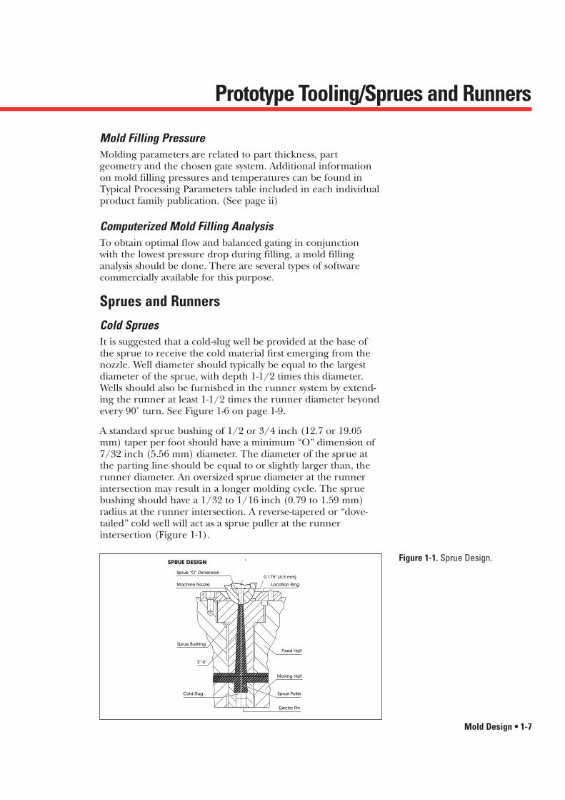
A standard sprue bushing of 1/2 or 3/4 inch (12.7 or 19.05mm) taper per foot should have a minimum “O” dimension of7/32 inch (5.56 mm) diameter. The diameter of the sprue atthe parting line should be equal to or slightly larger than, therunner diameter. An oversized sprue diameter at the runnerintersection may result in a longer molding cycle. The spruebushing should have a 1/32 to 1/16 inch (0.79 to 1.59 mm)radius at the runner intersection. A reverse-tapered or “dove-tailed” cold well will act as a sprue puller at the runner intersection (Figure 1-1).
Figure 1-1. Sprue Design.
�����������������������������������
Cycle time may be reduced by more positive sprue extraction(Figure 1-2), attained by reducing the diameter of the cold well (2) and/or adding gussets (3) or (4) on either side of the sprue.
�
�
����
��
��
��
��
��
��
��
��
����
�
�
����
����
���������
�����������
(1) Standard Sprue
(2) Reduced Cold Well
(3) Gussets
A A
(4) Reduced Cold Well and Gussets
Section A A Section A A
A A
Mold Design
1-8 • Mold Design
Figure 1-2. Sprue Puller ReverseTaper Modification.
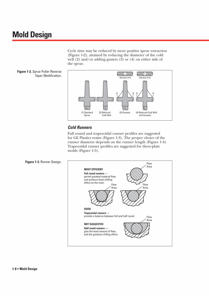
Cold RunnersFull round and trapezoidal runner profiles are suggested for GE Plastics resins (Figure 1-3). The proper choice of therunner diameter depends on the runner length (Figure 1-4).Trapezoidal runner profiles are suggested for three-plate molds (Figure 1-5).
������������
��������
��
������������
��
MOST EFFICIENTFull round runners —permit greatest material flowand produce least chillingeffect on the resin.
GOODTrapezoidal runners —provide a balance between full and half round.
FlowArea
NOT SUGGESTEDHalf round runners —give the least amount of flow, and the greatest chilling effect.
FlowArea
FlowArea
FlowArea
��
Figure 1-3. Runner Design.

Sprues and Runners
Mold Design • 1-9
Figure 1-6 shows cold well size and location of runner vents.
On multiple-cavity molds with primary and secondary runners,the primary runner should extend beyond the intersection ofthe secondary runner in order to provide a cold well for therunner flow front.
Figure 1-4. Suggested RunnerDiameters.
��
D
Sprue Secondary Runner (d)Primary Runner (D)L = 3" or lessL = 3" to 10"L = 10" or mored = .75D (0.250" min.)
D = 0.250"D = 0.312"D = 0.375"
d
L
Figure 1-5. Trapezoidal RunnerProfiles.Design Alternative
Full RadiusEquivalent Runner Diameter R
Rin. mm in. mm in. mm
3/16 4.8 1/4 6.4 3/16 4.8
1/4 6.4 5/16 7.9 1/4 6.4
5/16 7.9 7/16 11.1 5/16 7.9
3/8 9.5 1/2 12.7 3/8 9.5
W D
D
W
15°
����������
����������
Figure 1-6. Mold Design Runners.
DCold Well
1.5 x D
Vent to Atmosphere
Part
Flow Direction
ColdWell

Mold Design
1-10 • Mold Design
Runner length should be kept at a minimum. Parts requiringclose dimensional control in multi-cavity molds should have bal-anced runner systems (Figure 1-7). Close tolerance parts shouldnot be designed into family mold layouts.
ColdWell
Cavities
MainSprue
Sprue
��
Figure 1-7. Eight-Cavity BalancedRunner.
Hot SpruesGE resins can be processed in most types of heated sprue bush-ings. However, it is suggested that externally heated bushings be used (Figure 1-8). Heater power of 50 watts/cubic inch ofheated steel is suggested for hot sprue bushings and manifolds.In addition, contact areas should be stress-relieved and, wherepossible, should utilize stainless steel or titanium inserts forinsulation. Precise temperature control at the tip of the dropmust be maintained to help ensure proper molding. Heatersshould be located along the entire length of the drop andplaced in such a way as to provide the proper amount of heatdirectly to the gate area. The thermocouple should be locatedas near the tip as possible (Figure 1-9). The amount of surfacecontact between the drop and the mold should be kept to aminimum (Figure 1-8). This can be accomplished by relievingmost of the steel around the drop. The inside diameter of thedrop should be no less than 5/16 inch (7.94 mm).
��������������������
��������������������
3/4"R
Air GapAir Gap
2" dia.Min. 5/16"Bore
ProportionalHeat Density
1" dia.
Gate dia.0.156" to 0.187"
(Zero Land)
7°-9°
Figure 1-8. Heated Sprue Bushing.

Sprues and Runners
Mold Design • 1-11
Hot RunnersThe following information is intended only to offer generalguidance in the selection and design of hot runner systems,since specific configurations will vary according to individualapplication requirements.
Hot runner systems have been used successfully for small partsin multi-cavity molds and for large multi-gated parts such asbusiness machine housings and automotive instrument panels.
In the hot runner system, the resin is injected from themachine nozzle into a heated distribution manifold. The resinis kept in the molten state as it flows through the internal pas-sages of the manifold to the bushings and into the mold cavi-ties. The manifold is an extension of the heating cylinder;therefore, it is important that precise temperature control beprovided. Internally heated runnerless molding systems are notsuggested because of the no-flow areas and higher pressuredrops inherent in these systems. This could lead to extendedresidence time, material degradation and excessive pressures ornon-fill conditions.
Figure 1-9. Enlarged View of HotSprue Bushing Tip.
����
Reverse Taper Area
Heater Coils
Melt Flow
Housing
Zero Land Area
Mold Design
1-12 • Mold Design
Hot Runner Benefits• Although tooling can be more costly, it offers the opportunity for
thinner, more economical wall sections based on design rather thanflow constraints.
• The part can be gated in several locations enabling design flexibility. Hot runner systems can effectively shorten flow lengthsin long part or multi-cavity tools.
• Potential for eliminating regrind and secondary operations (norunners and sprues to remove and regrind).
• Reduce cycle times by eliminating sprue/runner intersections andthe need to wait until sprue sets up.
• Hot melt at cavity helps to improve quality. No significant tempera-ture and pressure losses in runners. Fewer molded-in stresses.
Individually-controlled heat zones are strongly suggested. Considerations for hot runner systems are listed below:
Hot Runner Systems1. Passages should be externally heated and designed to eliminate hot
spots (i.e., 4 heaters symmetrically positioned around flow passages).
2. To attain proper manifold heating, a minimum of 50 watts/cubicinch of steel should be applied with heaters distributed evenlythroughout the manifold.
3. Manifold passage should be 0.50 inch (12.7 mm) minimum. Largeparts and long flow lengths require larger diameters.
4. Passages should be streamlined with no dead spots for materialhang-up and degradation. Where there is a corner, the manifoldflow channel should have contoured end plugs.
5. Voltage proportional temperature controls are suggested to main-tain uniform temperatures.
6. Nozzles should be short and straight through. Nozzles over 6 incheslong should have 2 zones of temperature control.
7. The manifold block and drops should be properly insulated frommating steel with 0.03 inch (0.79 mm) air gap with minimummetal-to-metal contact and stainless steel or titanium support pads.
8. Nozzle drops should have external heaters that extend at least evenwith or beyond the minimum nozzle orifice point.
9. There should be separate closed loop controllers for each nozzle.
10. Resin melt temperature in the manifold and the drops should bethe same as the melt temperature in the cylinder.
11. Insulated runner systems are not appropriate for use with engineering thermoplastic resins.
12. With ULTEM resins beware of particular valve gated hot runner systems due to inherent hang-up areas that may cause part streaking.

Gating
Mold Design • 1-13
GatingThe basic considerations in gate location are part design, flow,and end-use requirements. As a general guideline, the followingpoints should be kept in mind:
• Large parts that require multiple gates should includegates that are positioned close enough together toreduce pressure loss. This will help provide good weldline strength by minimizing cooling where the leadingedges of resin flow come together. Gating dimensionsshould provide resin fill at reasonable pressures and fill speeds.
• Gate land lengths should be kept as short as possible.
• An impinging gate will help ensure that the incomingflow is directed against the cavity wall or core to avoid jetting.
• To avoid trapped gas, the resin flow from the gatesshould direct air toward the vents.
• Gates should be located to provide flow from thick tothin sections; to minimize weld lines; and away fromimpact or other stressed areas.
• To minimize jetting, splay and gate blush, the gates shouldbe located at right angles to the runner (Figure 1-10).
• Direct gating to a cosmetic surface may cause surfaceimperfections.
Sprue Sprue
Sprue Sprue
Figure 1-10. Runner to Gate(Indirect Approach).
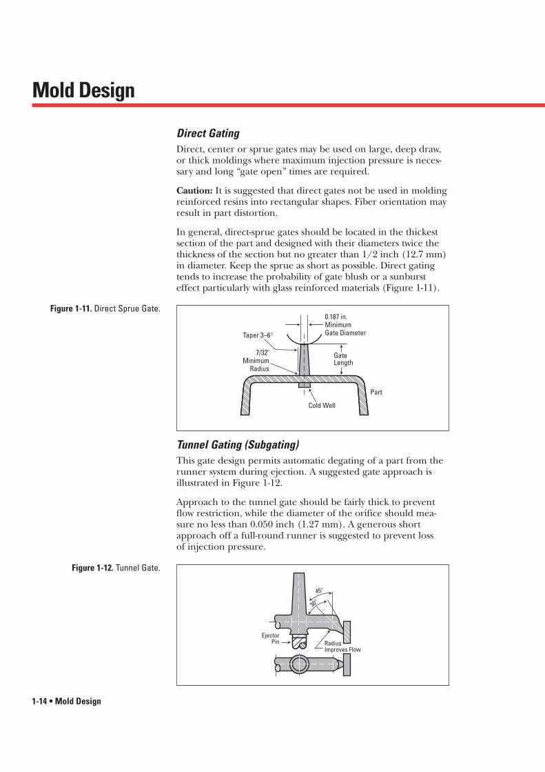
Tunnel Gating (Subgating)This gate design permits automatic degating of a part from therunner system during ejection. A suggested gate approach isillustrated in Figure 1-12.
Approach to the tunnel gate should be fairly thick to preventflow restriction, while the diameter of the orifice should mea-sure no less than 0.050 inch (1.27 mm). A generous shortapproach off a full-round runner is suggested to prevent loss of injection pressure.
Mold Design
1-14 • Mold Design
Direct GatingDirect, center or sprue gates may be used on large, deep draw,or thick moldings where maximum injection pressure is neces-sary and long “gate open” times are required.
Caution: It is suggested that direct gates not be used in moldingreinforced resins into rectangular shapes. Fiber orientation mayresult in part distortion.
In general, direct-sprue gates should be located in the thickestsection of the part and designed with their diameters twice thethickness of the section but no greater than 1/2 inch (12.7 mm)in diameter. Keep the sprue as short as possible. Direct gatingtends to increase the probability of gate blush or a sunbursteffect particularly with glass reinforced materials (Figure 1-11).
����������
0.187 in.MinimumGate Diameter
7/32"Minimum
Radius
Taper 3–6°
GateLength
Cold Well
Part
Figure 1-11. Direct Sprue Gate.
Figure 1-12. Tunnel Gate.
�������
45°
30°
Radius Improves Flow
EjectorPin
��������
����

Gating
Mold Design • 1-15
If the gate is not close to the sprue, it is suggested that an ejec-tor pin be positioned near the gate as illustrated in Figure 1-13.
Figure 1-13. Tunnel Gate.
������������
������������
����������������
���
������������������
30°15°
Gate DiameterR = 0.062" (1.6mm)Ejector Pin
45°
Pin Point GatingPin point gating (Figure 1-14) is used for three-plate molding.Diameters of gates for three-plate molds should be between0.050 and 0.100 inch (1.27 and 2.53 mm). A gate with no landis suggested to direct the break-off to ease automatic ejectionfrom the runner system. If attempts are made to reduce gatevestige left from the mold design (vestige shown on Figure 1-14),impact performance may be reduced because notches are created where the gate separates from the part.
������������������������Sucker Pin
Part
Gate
Radii Flow Path (0.062" R)
(Offset Sucker Pinout of Flow Path)
Breakpoint“Zero” Land Length 3° Side Taper per Side
0.050" to 0.100" Gate Dia.Vestige
90°
Flow
Figure 1-14. Pin Point Gate.

Modified Fan GatingFor flat, thin-walled sections, modified fan gating can minimizejetting and splay while significantly reducing high stresses causedby mold packing. The runner approach should be liberal andpositioned 90˚ to the gate using as short a land length as possi-ble (Figure 1-16). Smooth radii and transitions between runnersand gates are suggested. Cold well extensions should be a mini-mum of 1-1/2 times the runner diameter. If gate blush or highstress persists, it is suggested that the cold well be extended.(Normally 2 to 3 times the runner diameter is sufficient.)
Mold Design
1-16 • Mold Design
Edge GatingEdge gates are the most commonly used gates in injectionmolding. For optimum resin flow, the height or thickness of the gate should generally be 85 to 100% of the wall thicknessup to 0.125 inch (3.2 mm). The gate width should be 2 timesthe depth. A radius should be located at the junction of themolded part to prevent surface splay and to minimize molded-in stresses (Figure 1-15). A land length of 0.020 to 0.040 inch(0.50 to 1.01 mm) is suggested.
Figure 1-16. Modified Fan Gate.
�
Minimum Cold Well Extension11/2 x Runner Diameter
Sprue
Runner Diameter0.250"Minimum
Gate Width 11/2 to 2x Depth
������
����
Part
Land Length0.020" to 0.040"
Minimum Cold Well Extension11/2 x Runner Diameter
Gate Width 2 x Depth
0.125"
Gate Depth85 to 100%of WallThickness
Part
Figure 1-15. Edge Gating.

Gating
Mold Design • 1-17
Diaphragm GatingDiaphragm or disk gates (Figure 1-17) are suggested for cylin-drical parts requiring good concentricity and elimination ofweld lines for strength.
Figure 1-17. Diaphragm Gate.
������
��
��
��
��
Sprue
Diaphragm Thickness =Wall Section ofPart or Greater
Tapered Sprue Puller
Cutaway of a Circular Part
Land0.020" to 0.030" Long(13–20mm)60 to 100% of WallThickness
Flash GatingFlash gating (Figure 1-18) is an extension of fan gating. It is uti-lized to minimize warpage in flat designs or very large parts.
GateGate Depth = Part Thickness Minus 0.010" to 0.015"
A A
Part
Runner Part
Section A–A�
������
Figure 1-18. Flash Gate.
Mold Design
1-18 • Mold Design
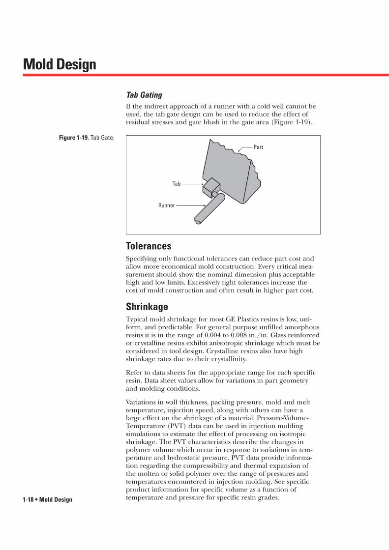
Tab GatingIf the indirect approach of a runner with a cold well cannot beused, the tab gate design can be used to reduce the effect ofresidual stresses and gate blush in the gate area (Figure 1-19).
Part
Tab
Runner
Figure 1-19. Tab Gate.
TolerancesSpecifying only functional tolerances can reduce part cost andallow more economical mold construction. Every critical mea-surement should show the nominal dimension plus acceptablehigh and low limits. Excessively tight tolerances increase thecost of mold construction and often result in higher part cost.
ShrinkageTypical mold shrinkage for most GE Plastics resins is low, uni-form, and predictable. For general purpose unfilled amorphous resins it is in the range of 0.004 to 0.008 in./in. Glass reinforcedor crystalline resins exhibit anisotropic shrinkage which must beconsidered in tool design. Crystalline resins also have highshrinkage rates due to their crystallinity.
Refer to data sheets for the appropriate range for each specificresin. Data sheet values allow for variations in part geometryand molding conditions.
Variations in wall thickness, packing pressure, mold and melttemperature, injection speed, along with others can have a large effect on the shrinkage of a material. Pressure-Volume-Temperature (PVT) data can be used in injection molding simulations to estimate the effect of processing on isotropicshrinkage. The PVT characteristics describe the changes in polymer volume which occur in response to variations in tem-perature and hydrostatic pressure. PVT data provide informa-tion regarding the compressibility and thermal expansion of the molten or solid polymer over the range of pressures andtemperatures encountered in injection molding. See specificproduct information for specific volume as a function of temperature and pressure for specific resin grades.

Cavity Venting
Mold Design • 1-19
Cavity VentingWhen molding GE resins it is extremely important for the cavityto be vented effectively to allow air displaced by the melt toescape. Proper venting helps prevent “dieseling” (or super-heatingof trapped air) and resulting burn marks at the end of the resinflow. This becomes even more critical in thin-wall parts and whenusing high injection speeds. Inadequate venting slows down thefilling rate, resulting in incomplete mold fill. Vents must be provided at points of last fill and at weld lines (Figure 1-20). On parts with large surface areas, vents should be placed every1 to 2 inches (25 to 50 mm) along the parting line.
Figure 1-20. Parting Line VentDetail.
������������
0.09" Land Length
CavityEdge Mold
1" to 2"
A
0.25"Minimum
A
Vent Depth
(See Text)
SECTION A-A
Vent to Atmosphere0.015"/0.03" Relief Depth
The suggested land length is 0.09 inch (2.29mm). The ventrelief to the atmosphere should be same width as the vents, witha suggested depth of 0.015 to 0.030 inch(0.38 to 0.76 mm) (Figure 1-20). Vent depths may vary from .0005 to .00075 forvarious crystalline resins to .003 for glass reinforced amorphousresins. See individual product sections in this publication foradditional information.
Full perimeter venting is suggested whenever possible to avoidair entrapment at the parting line.
Some fill patterns may trap gasses in areas that cannot be ventedat the parting line. To relive these gasses, vents can bemachined on ejector pins, sleeve ejectors and moving cores toallow venting through the mold.
Venting of the runner cold slug wells can also improve meltflow into the cavity.

Mold Temperature ControlAdequate temperature control of the core and cavity surfaces isimportant for producing quality parts. Dual zone or separatecontrollers are required for independent temperature controlof the two mold halves
Uniform mold temperature control is critical for maximizationof cycles and control of part tolerances. It is generally advisableto maintain less than a 20˚F (-7˚C) differential in steel tempera-tures over a large cavity or core and less than 5˚F (-15˚C) for small ones. Tighter controls will generally provide greater processing latitude.
Typical mold cooling for parts molded in GE resins wouldincorporate 1/2 inch (12.7 mm) or larger cooling channels (1-1/2 inches to 2 inches (38 to 50.8 mm) apart and 1/2 inch(12.7 mm) below cavity and core surfaces
Other temperature control devices such as Logic Seal,® Ther-mal Pins® or bubblers can be used to aid temperature controlin difficult-to-access areas.
Proper temperature control helps provide uniform heat acrossthe tool surface. Therefore, looping of the cooling channels asshown in Figure 1-22 is not recommended practice. Water mani-folds offer better control.
A large temperature differential across the mold surface createsdifferent cooling rates and results in molded-in stresses in theparts. For the same reason it is generally not practical to main-tain more than 40˚F (22˚C) difference between the core andcavity halves of the mold.
Mold Design
1-20 • Mold Design
+ +d
P
D
d – diameter 7/16"-9/16"(1.1113-1.4288 cm)
D – depth d to 2dP – pitch 3d to 5d
Figure 1-21. Cooling ChannelDimensions.
®Logic Seal is a Registered Trademark of Logic Devices, Inc.®Thermal Pins is a Registered Trademark of Noren Products, Inc.

Mold Temperature Control
Mold Design • 1-21
Figure 1-23. Bubbler (Cascading)for Spot Temperature Control.
CoolantFluid Out
CoolantFluid In
Figure 1-22. Cooling Channels.
Inlet125˚F(52˚C)
125˚F(52˚C)
135˚F(57˚C)
Not Recommended Looping Recommended ManifoldOutlet140˚F(60˚C)
130˚F(54˚C)
120˚F(49˚C)
Inlet115˚F (46˚C)
Outlet120˚F (49˚C)
Figure 1-24. Baffles in Series(Single Core).
����������������
������������
������������
���������
�� �� �Coolant Fluid Flow
Baffle
Additional information on mold surface temperatures can befound in the Typical Processing Parameter tables for each specific product line.

Mold Design
1-22 • Mold Design
����������������
Heat Pipe ConductsHeat to Coolant Fluid Line“O” Rings
Tall Mold Pinor Steel Section
CoolantFluid Line
Figure 1-25. Heat Pipes – ThermalPins.
Coolant Fluid InCoolant Fluid Out
DrilledChannels
Plugs
InsertCavity
Frame
Coolant Fluid In
Insert
Coolant Fluid Out
CavitySet InFrame
Figure 1-26. Coolant Fluid in Inserts.
��������
���������
Cavity
Cavity
“O” Rings Coolant ChannelsMachined ChannelsRound or Rectangular
1° Draft Suggested Minimum
Coolant Fluid Out
Coolant Fluid InFigure 1-27. Coolant Fluid LinesAround Circular Inserts.
Coolant in the frame only is not suggested.
Coolant in the core and cavityinserts and frame is preferred.

Mold Temperature Control
Mold Design • 1-23
�����������������������������
����������������� ����
SeparateControlAroundCavity Edge
Core
Cavity
1.5" to 2.0" 0.5"
Figure 1-28. Cavity and CoreTemperature Control.
Mold Build-UpWhen design permits, it is often desirable to incorporate anindependent temperature control channel around the periph-ery and under the edge detail of the parts. This can allow theuse of higher steel temperatures for the reduction of stress inthe molded part edges (Figure 1-28).
Heated mold surfaces are normally needed when molding GE resins.
Each part design must be reviewed for special cooling considerations.
Bubblers should be used for larger standing cores when conven-tional channeling is not possible (Figures 1-22 and 1-23). Bub-blers may be put in series in a single core. If bubblers are usedin individual cores, they should be parallel for individual cir-cuits. Heat pipes can be used in smaller standing sections as wellas chrome plated copper alloy inserts and pins (Figure 1-24).
The thermal conductivity of copper alloys can be as much asthree times greater than steel, thus offering special advantagesfor part designs with difficult cooling problems.
DraftDraft should be included on all surfaces in the line of draw ofthe die or a cam. Normally, the greater the draft angle, the easierit is to eject the part from the mold. Draft angles of 1˚ to 2˚ arepreferred. In tight details or special fit requirements, a 1/2˚minimum draft is advised.
In parts utilizing textured surfaces, additional draft is required.For textured walls in the line of draw of the mold, 1˚ additionaldraft for each 0.001 inch (0.03 mm) depth in texture is generally required.
Mold Design
1-24 • Mold Design
Part EjectionPart ejection can be accomplished in several ways. The use ofstripper plates is the most preferred method of part ejectionbecause of the large contact area. The greater the part ejectioncontact area the less the chance for induced stress in the moldedpart, resulting in better dimensional integrity and reduced partdamage. The use of stripper bars is another common methodof part ejection that has a good part contact area.
Knockout pins are a common method of part ejection. For opti-mum results it is important to use an ample number of knock-out pins. These pins should be designed with sufficient area toavoid compressing the resin surface and be located so that theydo not induce stress in the part. The use of sleeve ejectors forpart bosses is suggested.
External mold release agents are usually unnecessary for GEresins when molds are properly designed and polished. Draw-polishing is suggested for molds with thin ribs or minimal draftof vertical walls. In extreme cases, the use of various tool platingprocesses can aid in part ejection.