Embed Size (px)
Citation preview

Ingeniería y Universidad
ISSN: 0123-2126
Pontificia Universidad Javeriana
Colombia
Torres Quezada, Mauricio; Sagaró Zamora, Roberto; Broche Vázquez, Leonardo; Delisle Rodríguez,
Denis; López Delis, Alberto
Robotic Training System for Upper Limb Rehabilitation
Ingeniería y Universidad, vol. 18, núm. 2, julio-diciembre, 2014, pp. 235-252
Pontificia Universidad Javeriana
Bogotá, Colombia
Available in: http://www.redalyc.org/articulo.oa?id=47732595002
How to cite
Complete issue
More information about this article
Journal's homepage in redalyc.org
Scientific Information System
Network of Scientific Journals from Latin America, the Caribbean, Spain and Portugal
Non-profit academic project, developed under the open access initiative

Ing. Univ. Bogotá (Colombia), 18 (2): 235-252, julio-diciembre de 2014. ISSN 0123-2126
Robotic Training System for Upper Limb Rehabilitation1
Plataforma Robótica para la rehabilitación de miembros superiores2
Mauricio Torres Quezada3
Roberto Sagaró Zamora4
Leonardo Broche Vázquez4
Denis Delisle Rodríguez5
Alberto López Delis5
doi:10.11144/Javeriana.IYU18-2.rtsu
How to cite this article:TORRES QUEZADA, M.; SAGARÓ ZAMORA, R.; BROCHE VÁZQUEZ, L.; DELISLE RODRÍGUEZ, D., and LÓPEZ DELIS, A. Robotic Training System for Upper Limb Rehabilitation. Ingeniería y Universidad. 2014, vol. 18, no. 2, pp. 235-252. http://dx.doi.org/10.11144/Javeriana.IYU18-2.rtsu
1 Submitted on: December 24th, 2013. Accepted on: July 31st, 2014. This article is derived from the research project Desarrollo de tecnologías para rehabilitación muscular a partir del procesamiento de señales mioeléctricas de superficie y sensores propioceptivos, proyecto CAPES-MES 137/11, developed by the research group CBM-Grupo de Tribología, Universidad de Oriente, Cuba.2 Fecha de recepción: 24 de diciembre de 2013. Fecha de aceptación: 31 de julio de 2014. Este artículo se deriva del proyecto de investigación Desarrollo de tecnologías para rehabilitación muscular a partir del procesamiento de señales mioeléc-tricas de superficie y sensores propioceptivos, proyecto CAPES-MES 137/11, desarrollado por el grupo de investigación CBM-Grupo de tribología, Universidad de Oriente, Cuba.3 Polytechnic Institute “Juan Bosco”, Bogotá, D.C., Colombia.4 Tribology and Design Group, Mechanical and Design Department, Mechanical Engineering Faculty, University of Oriente, Santiago de Cuba, Cuba. E-mail: [email protected] Biophysical Medical Center, University of Oriente, Cuba.

236 Mauricio Torres Quezada, Roberto Sagaró Zamora, Leonardo Broche Vázquez, Denis Delisle Rodríguez, Alberto López Delis
Ing. Univ. Bogotá (Colombia), 18 (2): 235-252, julio-diciembre de 2014
AbstractBackground: Robot-assisted therapy or exoskeleton is an active mechanical device that can be easily adjusted to fit a different patient limb length, and is able to coordinate and amplify movements. The aim of this study focuses on developing a robotic training system and quantification methods for upper limbs rehabilitation in clinic environ-ments to be used in survivor stroke patients with motor disorders or loss of physical strength on one side of the body. Methods: From an integrated approach, a design of one exoskeleton is presented which allows patients perform complex movements in four degrees of freedom (DOF) rehabilitation system. The system is controlled by means of user interface developed with Lab view v8.6 software that supports control and user interaction with the exoskeleton; so it’s possible for therapist to modify the patient routine including new movements and a number of repetitions in articulating joints of shoulder, elbow and wrist. On other hand system permits bio-feedback of electromyogram patient activity during rehabilitation sessions. Results: Biomechanical analyses and structure design, implemen-tation of power systems, the development of the control system and user interface as well as its integration with the mechanical system is presented. Conclusions: A robot arm exoskeleton device with four DOF; able to develop complex, accurate and repetitive therapeutic routines for articulating joints of shoulder, elbow and wrist trough an interface is shown. The device permits to follow chrono-logically patient outcomes recording the electromyogram activity during rehabilitation progress.
Keywords biomechanics; exoskeleton; electromyographic signal
ResumenIntroducción: Un exoesqueleto se conceptualiza como un mecanismo estructural externo cuyos segmentos y articulaciones se corresponden con las del cuerpo humano y es capaz de coordinar y amplificar sus movimientos. El objetivo del trabajo se enfoca en desarrollar una tecno-logía de plataforma robótica de asistencia y métodos de cuantificación para la rehabilitación motora de miembros superiores en ambientes clínicos y ambulatorios para pa-cientes con afecciones motoras como resultados de enferme-dades cerebrovasculares. Métodos: Se presenta a partir de una concepción integradora el diseño del prototipo de un exoesqueleto que permite al paciente realizar movimientos combinados a partir de los cuatro grados de libertad que provee el dispositivo de rehabilitación. El sistema es contro-lado por medio de una interfaz de usuario desarrollada en Labview que soporta el control e interacción del usuario con el exoesqueleto, lo cual posibilita que el terapeuta puede modificar la rutina que debe realizar el paciente incluyendo nuevas trayectorias y el número de repeticiones a seguir por el exoesqueleto en las articulaciones de hombro, codo y muñeca. Adicionalmente, posibilita la retroalimentación visual de la actividad electromiográfica del paciente durante la rehabilitación. Resultados: Se presenta el diseño mecá-nico de la armadura, implementación de los sistemas de potencia, el desarrollo del sistema de control y de la interfaz de usuario así como su integración con el sistema mecánico. Conclusiones: Se desarrolla y pone en funcionamiento una avanzada plataforma robótica capaz de desarrollar diversas rutinas terapéuticas combinando 4 grados de libertad en hombro, codo y muñeca, capaz de controlar a través de la interfaz desarrollada desplazamientos regulados, exactos y repetitivos, así como seguir cronológicamente la evolución del paciente registrando la actividad mioeléctrica durante el proceso de rehabilitación.
Palabras claveBiomecánica; exoesqueleto; señal electromiográfica; control activo y pasivo
237Robotic Training System for Upper Limb Rehabilitation
Ing. Univ. Bogotá (Colombia), 18 (2): 235-252, julio-diciembre de 2014
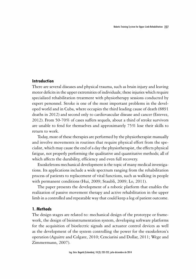
IntroductionThere are several diseases and physical trauma, such as brain injury and leaving motor deficits in the upper extremities of individuals; these injuries which require specialized rehabilitation treatment with physiotherapy sessions conducted by expert personnel. Stroke is one of the most important problems in the devel-oped world and in Cuba, where occupies the third leading cause of death (8891 deaths in 2012) and second only to cardiovascular disease and cancer (Estevez, 2012). From 50-70% of cases suffers sequels, about a third of stroke survivors are unable to fend for themselves and approximately 75% lose their skills to return to work.
Today, most of these therapies are performed by the physiotherapist manually and involve movements in routines that require physical effort from the spe-cialist, which may cause the end of a day the physiotherapist, the effects physical fatigue, not properly performing the qualitative and quantitative methods; all of which affects the durability, efficiency and even full recovery.
Exoskeletons mechanical development is the topic of many medical investiga-tions. Its applications include a wide spectrum ranging from the rehabilitation process of patients to replacement of vital functions, such as walking in people with permanent conditions (Hui, 2009; Staubli, 2009; Lo, 2011).
The paper presents the development of a robotic platform that enables the realization of passive movement therapy and active rehabilitation in the upper limb in a controlled and repeatable way that could keep a log of patient outcome.
1. MethodsThe design stages are related to: mechanical design of the prototype or frame-work, the design of bioinstrumentation system, developing software platforms for the acquisition of bioelectric signals and actuator control devices as well as the development of the system controlling the power for the exoskeleton’s operation (Aguirre and Colgate, 2010; Cenciarini and Dollar, 2011; Wege and Zimmermann, 2007).

238 Mauricio Torres Quezada, Roberto Sagaró Zamora, Leonardo Broche Vázquez, Denis Delisle Rodríguez, Alberto López Delis
Ing. Univ. Bogotá (Colombia), 18 (2): 235-252, julio-diciembre de 2014
Figure 1 presents the proposed rehabilitation of upper platform for passive and active modes of upper limb control. A segmented into two blocks visual interface allows the control of exoskeleton based on motion routines for program-ming and biofeedback of myoelectric signals acquired during the rehabilitation process, respectively. The signal acquisition is performed through a system designed for this purpose bioinstrumentation. Exoskeleton platform designed and built, is initially designed to operate in passive mode, which is activated by the information related to the motion routines that configure the physical therapist, to perform the therapy. Additionally, the system provides the ability to modify or create new routines and individualized movements for each patient.
Figure 1. Upper limb motor rehabilitation system
ExoskeletonBioinstrumentation
Control interface
Visual interface
Movements rehabilitate
Training stage
Myoelectric control algorithm learning bases on neural networkd
(signals registration in healthy limb)
Evaluation stage
Rehabilitation process in affected limb by motor dysfunction
(signals registration in affected limb)
1.1. Biomechanical study of the upper limbThe proposed system cannot be in conflict with the clinical practice for the re-covery of the affected limb and in medical terms is known as the therapeutic routine. Considering the impossibility of satisfying all possible exercises, especially those that incorporate hand movements, which greatly complex design; conceived routine includes movements from 4 degrees of freedom: flexion and
239Robotic Training System for Upper Limb Rehabilitation
Ing. Univ. Bogotá (Colombia), 18 (2): 235-252, julio-diciembre de 2014
shoulder extension, flexion and elbow extension, forearm supination/pronation and rotation of the humerus.
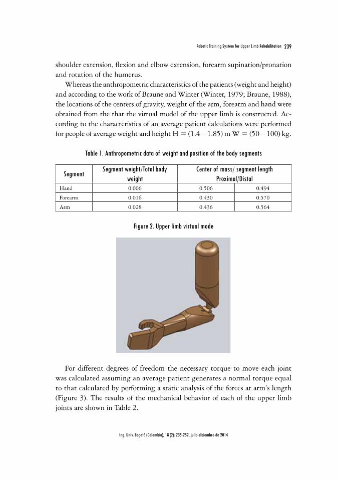
Whereas the anthropometric characteristics of the patients (weight and height) and according to the work of Braune and Winter (Winter, 1979; Braune, 1988), the locations of the centers of gravity, weight of the arm, forearm and hand were obtained from the that the virtual model of the upper limb is constructed. Ac-cording to the characteristics of an average patient calculations were performed for people of average weight and height H = (1.4 ‒ 1.85) m W = (50 ‒ 100) kg.
Table 1. Anthropometric data of weight and position of the body segments
SegmentSegment weight/Total body
weightCenter of mass/ segment length
Proximal/DistalHand 0.006 0.506 0.494
Forearm 0.016 0.430 0.570
Arm 0.028 0.436 0.564
Figure 2. Upper limb virtual mode
For different degrees of freedom the necessary torque to move each joint was calculated assuming an average patient generates a normal torque equal to that calculated by performing a static analysis of the forces at arm’s length (Figure 3). The results of the mechanical behavior of each of the upper limb joints are shown in Table 2.

240 Mauricio Torres Quezada, Roberto Sagaró Zamora, Leonardo Broche Vázquez, Denis Delisle Rodríguez, Alberto López Delis
Ing. Univ. Bogotá (Colombia), 18 (2): 235-252, julio-diciembre de 2014
Figure 3. Determination the necessary torque and DOF for each articulation
Flexion and shoulder extension Flexion and elbow extension
Forearm supination/pronation Rotation of the humerus
Table 2. Joint torque calculated for each DOF
Total body weight
(kg)
Shoulder Flexion/extension torque
(Nm)
Elbow Flexion/extension torque
(Nm)
Forearm pronation/supination torque
(Nm)
Humerus Rotation torque
(Nm)50 13.9 2.75 0.49 9.45
100 27.8 5.50 0.97 18.90
1.1.1. Actuator design
Because of the best actuator is the simplest, practical, lightweight and economi-cal, from the results of the biomechanical analysis of the upper extremity, it was decided to consider a design with the use of electric motors, gearboxes and sliding adjustment plates. When considering the torques produced by the weight of the arm and armature the power required moving each joint was determined. In these cases were selected 2-phase stepping motors (Table 3). The maximum speed of each joint was estimated as an average of 25 º/s. from the consensus of the designers and physiotherapists by own peculiarity of the routines used in the rehabilitation of patients.
241Robotic Training System for Upper Limb Rehabilitation
Ing. Univ. Bogotá (Colombia), 18 (2): 235-252, julio-diciembre de 2014
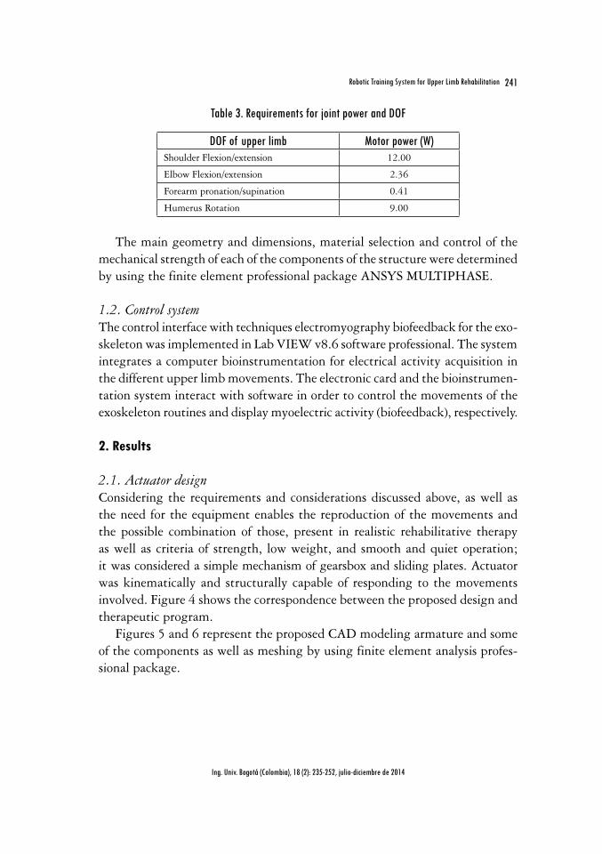
Table 3. Requirements for joint power and DOF
DOF of upper limb Motor power (W)Shoulder Flexion/extension 12.00
Elbow Flexion/extension 2.36
Forearm pronation/supination 0.41
Humerus Rotation 9.00
The main geometry and dimensions, material selection and control of the mechanical strength of each of the components of the structure were determined by using the finite element professional package ANSYS MULTIPHASE.
1.2. Control systemThe control interface with techniques electromyography biofeedback for the exo-skeleton was implemented in Lab VIEW v8.6 software professional. The system integrates a computer bioinstrumentation for electrical activity acquisition in the different upper limb movements. The electronic card and the bioinstrumen-tation system interact with software in order to control the movements of the exoskeleton routines and display myoelectric activity (biofeedback), respectively.
2. Results
2.1. Actuator design Considering the requirements and considerations discussed above, as well as the need for the equipment enables the reproduction of the movements and the possible combination of those, present in realistic rehabilitative therapy as well as criteria of strength, low weight, and smooth and quiet operation; it was considered a simple mechanism of gearsbox and sliding plates. Actuator was kinematically and structurally capable of responding to the movements involved. Figure 4 shows the correspondence between the proposed design and therapeutic program.
Figures 5 and 6 represent the proposed CAD modeling armature and some of the components as well as meshing by using finite element analysis profes-sional package.

242 Mauricio Torres Quezada, Roberto Sagaró Zamora, Leonardo Broche Vázquez, Denis Delisle Rodríguez, Alberto López Delis
Ing. Univ. Bogotá (Colombia), 18 (2): 235-252, julio-diciembre de 2014
Figure 4. Correspondence between the design and therapeutic routines. (a) Routine that includes shoulder flexion and elbow and wrist pronation-supination. (b) Routine including shoulder
extension, elbow flexion and forearm supination-pronation
Figure 5. Modeling CAD and meshing exoskeleton armature
243Robotic Training System for Upper Limb Rehabilitation
Ing. Univ. Bogotá (Colombia), 18 (2): 235-252, julio-diciembre de 2014
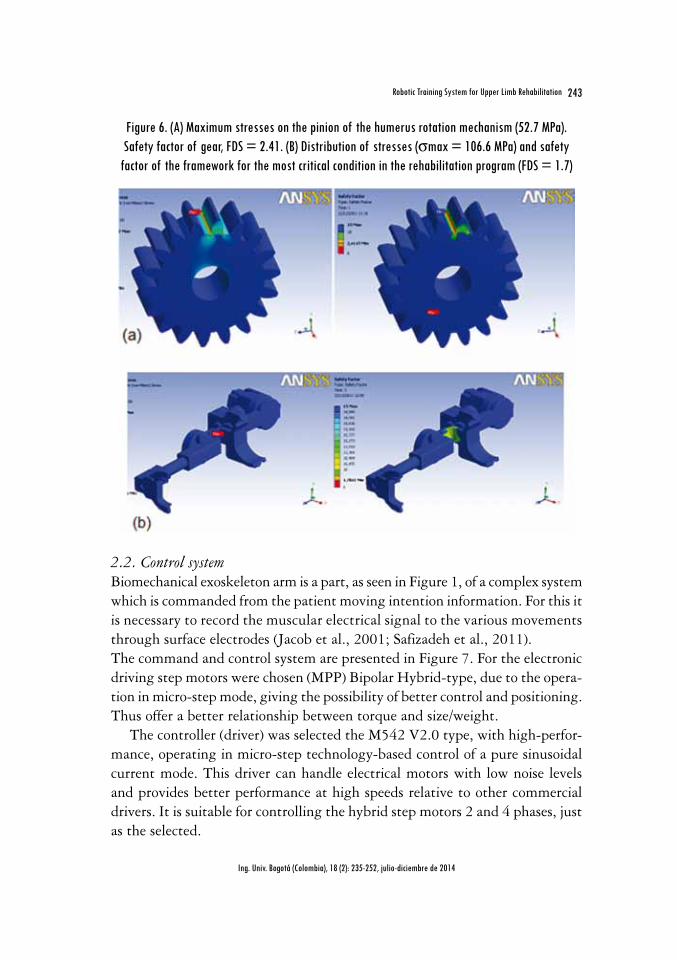
Figure 6. (A) Maximum stresses on the pinion of the humerus rotation mechanism (52.7 MPa). Safety factor of gear, FDS = 2.41. (B) Distribution of stresses (smax = 106.6 MPa) and safety
factor of the framework for the most critical condition in the rehabilitation program (FDS = 1.7)
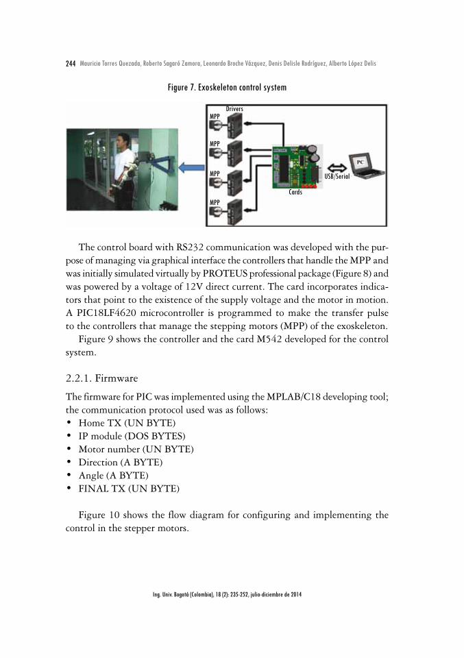
2.2. Control system Biomechanical exoskeleton arm is a part, as seen in Figure 1, of a complex system which is commanded from the patient moving intention information. For this it is necessary to record the muscular electrical signal to the various movements through surface electrodes (Jacob et al., 2001; Safizadeh et al., 2011). The command and control system are presented in Figure 7. For the electronic driving step motors were chosen (MPP) Bipolar Hybrid-type, due to the opera-tion in micro-step mode, giving the possibility of better control and positioning. Thus offer a better relationship between torque and size/weight.
The controller (driver) was selected the M542 V2.0 type, with high-perfor-mance, operating in micro-step technology-based control of a pure sinusoidal current mode. This driver can handle electrical motors with low noise levels and provides better performance at high speeds relative to other commercial drivers. It is suitable for controlling the hybrid step motors 2 and 4 phases, just as the selected.
244 Mauricio Torres Quezada, Roberto Sagaró Zamora, Leonardo Broche Vázquez, Denis Delisle Rodríguez, Alberto López Delis
Ing. Univ. Bogotá (Colombia), 18 (2): 235-252, julio-diciembre de 2014
Figure 7. Exoskeleton control system
Drivers
Cards
MPP
MPP
MPP
MPP
USB/Serial
The control board with RS232 communication was developed with the pur-pose of managing via graphical interface the controllers that handle the MPP and was initially simulated virtually by PROTEUS professional package (Figure 8) and was powered by a voltage of 12V direct current. The card incorporates indica-tors that point to the existence of the supply voltage and the motor in motion. A PIC18LF4620 microcontroller is programmed to make the transfer pulse to the controllers that manage the stepping motors (MPP) of the exoskeleton.
Figure 9 shows the controller and the card M542 developed for the control system.
2.2.1. Firmware
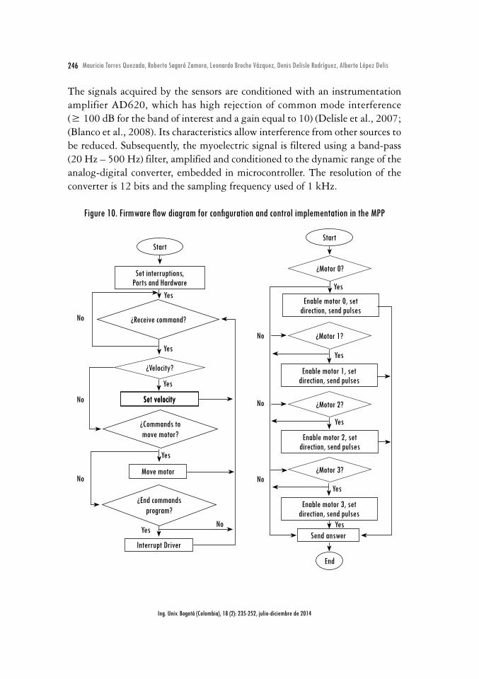
The firmware for PIC was implemented using the MPLAB/C18 developing tool; the communication protocol used was as follows:• Home TX (UN BYTE) • IP module (DOS BYTES) • Motor number (UN BYTE) • Direction (A BYTE) • Angle (A BYTE) • FINAL TX (UN BYTE)
Figure 10 shows the flow diagram for configuring and implementing the control in the stepper motors.

245Robotic Training System for Upper Limb Rehabilitation
Ing. Univ. Bogotá (Colombia), 18 (2): 235-252, julio-diciembre de 2014
Figure 8. Circuit simulated ISIS-PROTEUS card developed
Figure 9. Control exoskeleton module: (A) power supply and controllers, and (B) control board
Power supply
ControllerM542
2.2.2. Electromyographic signals acquisition module
Figure 11 shows a block diagram of the process of acquisition for electromyo-graphic signals (EMG). The myoelectric signal acquisition was performed using surface Ag-AgCl electrodes positioned on the agonist and antagonist muscles.
246 Mauricio Torres Quezada, Roberto Sagaró Zamora, Leonardo Broche Vázquez, Denis Delisle Rodríguez, Alberto López Delis
Ing. Univ. Bogotá (Colombia), 18 (2): 235-252, julio-diciembre de 2014
The signals acquired by the sensors are conditioned with an instrumentation amplifier AD620, which has high rejection of common mode interference (≥ 100 dB for the band of interest and a gain equal to 10) (Delisle et al., 2007; (Blanco et al., 2008). Its characteristics allow interference from other sources to be reduced. Subsequently, the myoelectric signal is filtered using a band-pass (20 Hz – 500 Hz) filter, amplified and conditioned to the dynamic range of the analog-digital converter, embedded in microcontroller. The resolution of the converter is 12 bits and the sampling frequency used of 1 kHz.
Figure 10. Firmware flow diagram for configuration and control implementation in the MPP
Start
Set interruptions, Ports and Hardware
¿Receive command?
¿Velocity?
¿Commands to move motor?
¿End commands program?
Move motor
Interrupt Driver
No
No
No
No
Yes
Yes
Yes
Yes
Yes
Set velocitySet velocity
Start
¿Motor 0?
¿Motor 1?
¿Motor 2?
¿Motor 3?
No
No
No
Yes
Yes
Yes
Yes
Yes
Enable motor 0, set direction, send pulses
Enable motor 2, set direction, send pulses
Enable motor 1, set direction, send pulses
Enable motor 3, set direction, send pulses
Send answer
End

247Robotic Training System for Upper Limb Rehabilitation
Ing. Univ. Bogotá (Colombia), 18 (2): 235-252, julio-diciembre de 2014
Figure 11. Block diagram of the acquisition process
Muscle Electrodes Electromyograph Register
Amplifier and Filter
A/DConvertor
DigitalProcessingSensorSinal
2.2.3. Description of the proposed interface
The control interface with electromyography biofeedback techniques for the exoskeleton was implemented in LabVIEW v8.6 software professional. It is provided with a main panel divided into the following sections: selector, editor of motion routines and graphic display of the myoelectric activity. As shown in Figure 12a aspects such as the selection of the desired routine, speed selector and number of repetitions are considered, in addition to enable the option to include new routines according to the degrees of freedom implemented. In biofeedback process three options of graphical interfaces allow the interac-tion with the patient. One of these variants has animated interfaces during the rehabilitation process (Figure 12b).
The designed interface also allows the configuration of the EMG channels used during the acquisition process, the gain configuration and selection of the corresponding muscles on each channel. While selecting muscles, the therapist can be accompanied by a human map provided with different views and locations associated with surface electrodes in bipolar configuration (Figure 13). All con-figurations can be stored by the system.
The second (Figure 14) and third (Figure 15) permit to visualize the varia-tion of raw EMG signal and its envelope, respectively. These alternative graphs allow the physiotherapist and the patient to know the start and end of muscle activation and the amplitude values the signal.

248 Mauricio Torres Quezada, Roberto Sagaró Zamora, Leonardo Broche Vázquez, Denis Delisle Rodríguez, Alberto López Delis
Ing. Univ. Bogotá (Colombia), 18 (2): 235-252, julio-diciembre de 2014
Figure 12. (a) Biofeedback techniques main panel interface, and (b) Myoelectrical signal amplitude according to the position the bar code
Con el codo extendido, hombro en flexión o ante versión de 45 grados y la mano en posición neutra, el paciente intenta elevar anteriormente el antebrazo (tope 140 grados). Pronación y supinaci´n antebrazo y a continuación extensión codo.
5,0 -
4,5 -
3,5 -
3,0 -
2,5 -
2,0 -
1,5 -
1,0 -
0,5 -
0,0 -
5,0 -
4,5 -
3,5 -
3,0 -
2,5 -
2,0 -
1,5 -
1,0 -
0,5 -
0,0 -
5,0 -
4,5 -
3,5 -
3,0 -
2,5 -
2,0 -
1,5 -
1,0 -
0,5 -
0,0 -
5,0 -
4,5 -
3,5 -
3,0 -
2,5 -
2,0 -
1,5 -
1,0 -
0,5 -
0,0 -
5,0 -
4,5 -
3,5 -
3,0 -
2,5 -
2,0 -
1,5 -
1,0 -
0,5 -
0,0 -
5,0 -
4,5 -
3,5 -
3,0 -
2,5 -
2,0 -
1,5 -
1,0 -
0,5 -
0,0 -
5,0 -
4,5 -
3,5 -
3,0 -
2,5 -
2,0 -
1,5 -
1,0 -
0,5 -
0,0 -
5,0 -
4,5 -
3,5 -
3,0 -
2,5 -
2,0 -
1,5 -
1,0 -
0,5 -
0,0 -
Valor inferior al deseado Valor superior al deseado Valor deseado
(a)
(b)
Processing EMG signals is based in the preprocessing the acquired signal, the envelope detection and calculation of the muscle activation amplitude. The method used for this purpose in this work is the root mean square, see Figure 15. This parameter characterizes the signal according to the estimate energy, related to the amplitude at a certain time interval and represents the average power of signal.

249Robotic Training System for Upper Limb Rehabilitation
Ing. Univ. Bogotá (Colombia), 18 (2): 235-252, julio-diciembre de 2014
Figure 13. Configuration Window EMG channels
Figure 14. Myoelectric signal captured in the anterior deltoid muscle

250 Mauricio Torres Quezada, Roberto Sagaró Zamora, Leonardo Broche Vázquez, Denis Delisle Rodríguez, Alberto López Delis
Ing. Univ. Bogotá (Colombia), 18 (2): 235-252, julio-diciembre de 2014
Figure 15. Calculate the root mean square: (A) filtered signal, (B) rectified signal envelope, and (C) signal
3000 3200 3400 3600 3800 4000 4200 4400 4600 4800 5000
3000 3200 3400 3600 3800 4000 4200 4400 4600 4800 5000
time (ms)
time (ms)
time (ms)150 160 170 180 190 200 210 220 230 240 250
1
0.5
0
1
0.5
0
1
0.5
0
ampli
tude
(uv)
ampli
tude
(uv)
ampli
tude
(uv)
a)
b)
c)
ConclusionsAccording to one therapeutic routine, considering clinical environment, using 4 degrees of freedom and using the possibility of combining these movements for rehabilitation of the upper limbs; the developed mechanical system is able to simulate the kinematics required regarding movements and is adjustable in functional parameters. The presented interface allows control of the movements of the exoskeleton, and the configuration of the analog channels EMG prototype. The implemented functions allow communication with the exoskeleton’s control board and EMG prototype. Digital processing methods were tested and showed their effectiveness for detecting the envelope of the EMG signal that is used for patient biofeedback. The next steps are directed towards the implementation of a clinical protocol in subjects presenting muscle dysfunction in the upper limb, with the objective of evaluating the results derived from manual therapy and made from the passive control.
251Robotic Training System for Upper Limb Rehabilitation
Ing. Univ. Bogotá (Colombia), 18 (2): 235-252, julio-diciembre de 2014
AcknowledgementsThe authors wish to acknowledge the collaboration of the Polytechnic Institute of Colombia Juan Bosco and the Brazilian Government Program Coordination for the Improvement of Higher Education (CAPES) through the research project CAPES-MES 137/11.
ReferencesAGUIRRE-OLLINGER, G. and COLGATE, J. E. Design of an active one-degree-of-freedom
lower-limb exoskeleton with inertia compensation. The International Journal of Robotics Research. 2010. DOI: 10.1177/0278364910385730.
BLANCO, R.; DELISLE, D.; GARCÍA, J.C.; DÍAZ, C., and LÓPEZ, N. Registrador de elec-tromiogramas destinado a estudios de la marcha. Bioingeniería y Física Médica Cubana. 2008, vol. 9, no. 3.
BRAUNE, W. Determination of body moments of inertia of the human body and its limbs. Berlin: Springer-Verlag, 1988.
CENCIARINI, M.; DOLLAR, A. Biomechanical considerations in the design of lower limb exoskeletons. IEEE International Conference on Rehabilitation Robotics Rehab Week Zurich, 2011. ETH Zurich Science City, Switzerland, June 29 - July 1, 2011.
DELISLE, D.; BLANCO, R.; GARCÍA, J.C.; DÍAZ, C.; LÓPEZ, N.; MARTÍNEZ, A. Módulo digital para electromiógrafo portátil. Ciencia y Tecnología. 2007, vol. 11, pp. 173-178.
ESTÉVEZ, A. Grado de discapacidad en pacientes hemipléjicos del “Policlínico Docente Uni-versitario del Cerro”. Revista Cubana de Medicina General Integral. 2012, vol. 28, no. 4, pp. 682-693.
HUI, Y. Controlling a powered exoskeleton system via electromyographic signals. Proceedings of the 2009 IEEE International Conference on Robotics and Biomimetics December 19 -23, 2009, Guilin, China. pp. 349-353.
LO, H.S. and XIE, S.Q. Exoskeleton robots for upper-limb rehabilitation: State of the art and future prospects. Med Eng Phys. 2011. DOI: 10.1016/j.medengphy.2011.10.004.
ROSEN, J. and MOSHE, B. A myosignal-based powered exoskeleton system. IEEE Transaction on Systems, Man, and Cybernetics—part A: SYSTEMS AND HUMANS. 2001, vol. 31, no. 3.
SAFIZADEH, M. R. and HUSSEIN, M. Kinematic analysis of powered lower limb orthoses for gait rehabilitation of hemiplegic and hemiparetic patients. International Journal of Mathematical Models and Methods in Applied Sciences. 2011, vol. 5, no. 3, pp. 490-498.
STAUBLI, P. Effects of intensive arm training with the rehabilitation robot ARMin II in chronic stroke patients: four single-cases. Journal of Neuro Engineering and Rehabilitation. 2009, vol. 6, no. 46. DOI: 10.1186/1743-0003-6-46.
USER’S MANUAL for M542 V2.0. High performance microstepping driver. Version 1.0, 2008.
252 Mauricio Torres Quezada, Roberto Sagaró Zamora, Leonardo Broche Vázquez, Denis Delisle Rodríguez, Alberto López Delis
Ing. Univ. Bogotá (Colombia), 18 (2): 235-252, julio-diciembre de 2014
WEGE, A. and ZIMMERMANN, A. Electromyography sensor based control for a hand exos-keleton. Proceedings of the 2007 IEEE International Conference on Robotics and Biomimetics December 15 -18, 2007, Sanya, China.
WINTER, D.A. Biomechanics of human movement. New York: John Wiley and Sons, 1979.