Embed Size (px)
Citation preview

© Festo Didactic 52667-20 11
The solar thermal training system provides a small-scale hot water supply, radiator, and floor heating system to teach students how solar radiant energy can be harnessed from the sun and converted to solar thermal energy in order to elevate air, water, and surface temperatures within a residential home or commercial business.
Figure 6. The solar thermal training system.
Trainer Familiarization and Safety
Information Job Sheet 2
Job Sheet 2 – Trainer Familiarization and Safety
12 © Festo Didactic 52667-20
The training system can be configured to exchange and store thermal energy. It permits experimenting with open and closed loop heating systems. The main (primary) loop can collect the thermal energy, and a secondary loop can distribute and apply heat to a gas, liquid, or solid in order to dissipate the thermal energy.
In addition to miscellaneous plumbing fittings and fixtures, the following main system components are commonly found in heating systems and are required to complete the solar thermal energy training. The trainer also includes several safety devices and features, as described below.
Mobile workstation (training system frame and assembly)
The mobile workstation provides a place to mount and store all of the training system modules and materials. See Figure 6.
Solar collector (flat plate type)
The solar collector converts radiant energy (light) into thermal energy (heat) and transfers that energy to a fluid, commonly water or a water and antifreeze mixture. The polycarbonate frame is thermally insulated with 70 mm thick mineral wool insulation and contains an aluminum-copper absorber. The absorber has a highly selective vacuum coating with an absorption rating of 95%. Glazing is achieved by a solar glass (ESG) pane. Content volume is 0.60 L with an absorption area of 0.96 m2. Its outer dimensions are 1200 mm x 800 mm.
Figure 7. Solar collector.

Job Sheet 2 – Trainer Familiarization and Safety
© Festo Didactic 52667-20 13
Collector inlet (with shutoff valve)
The collector inlet is the cold water input to the solar collector, which is often temperature monitored for efficiency calculations. The attached ball valve helps to ensure that hot water cannot spill out of the collector during system maintenance. The inlet is at the bottom of the solar collector.
Figure 8. Collector inlet.
Collector outlet
The collector outlet is the hot water output from the solar collector, which is often temperature monitored for efficiency calculations. The outlet is at the top of the solar collector. The top of the outlet is normally capped. However, for draindown and drainback systems, a vacuum breaker can be attached.
Figure 9. Collector outlet (with end cap or vacuum breaker).

Job Sheet 2 – Trainer Familiarization and Safety
14 © Festo Didactic 52667-20
Circulator pumps (2)
The circulator pumps are water pumps that are driven by an integrated electric
motor and impeller assembly that must be controlled electronically. The
maximum flow rate is 79.49 LPM (at 0 m) and the maximum head is at 5.80 m
(with 0 LPM flow). The circulator pumps can work in the following modes:
Mode I: Fixed to slow speed. In this mode, the pump runs at a constant
speed, following a constant curve (the minimum curve) under all operating
conditions.
Mode II: Fixed to medium speed. In this mode, the pump runs at a constant
speed, following a constant curve (the medium curve) under all operating
conditions.
Mode III: Fixed to high speed. In this mode, the pump runs at a constant
speed, following a constant curve (the maximum curve) under all operating
conditions.
Constant pressure I: The duty point of the pump moves left and right along
the lowest constant-pressure curve depending on the water demand in the
system, keeping the head constant.
Constant pressure II: The duty point of the pump moves left and right along
the middle constant-pressure curve depending on the water demand in the
system, keeping the head constant.
Constant pressure III: The duty point of the pump moves left and right along
the highest constant-pressure curve, depending on the water demand in the
system, keeping the head constant.
AUTO adapt: In this mode, the control of the pump performance is automatic,
within the defined performance range. The pump performance is
automatically adjusted to the system demands over time.
In the job sheets, “Mode III” is used, so that the pump works at maximum power.
Job Sheet 2 – Trainer Familiarization and Safety
© Festo Didactic 52667-20 15
Figure 10. Circulator pump.
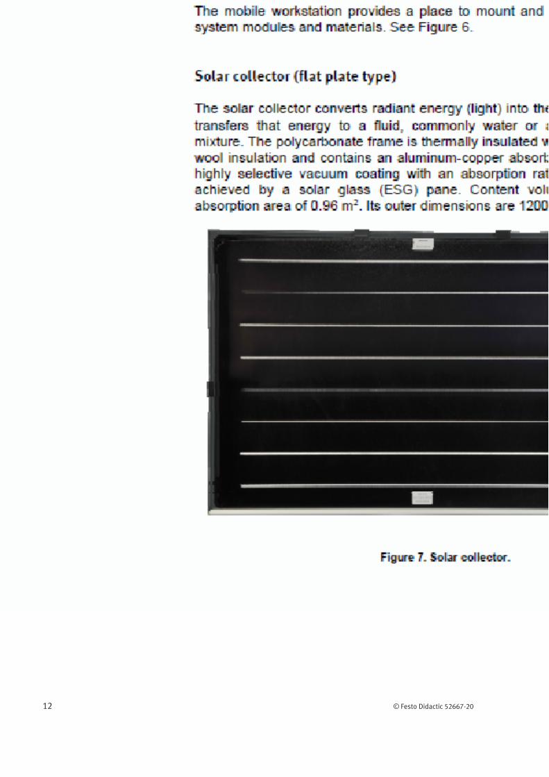
Storage tank
The storage tank is a stainless-steel, thermally-insulated vessel that is used to
hold thermal energy (heat) in a storage medium (water) for later use. It
contains two internal heat exchangers (see below) and a temperature sensor.
The tank includes a drain port with a shut-off valve and a return port, both of
which are described in greater detail below. It can hold up to 51.10 L, but is
usually only filled to about 37.85 L.
Figure 11. Storage tank.

Job Sheet 2 – Trainer Familiarization and Safety
16 © Festo Didactic 52667-20
Tank heat exchangers (2 coil types)
The tank heat exchangers are two coils of copper tubing that are located inside the storage tank (one on the top and one on the bottom) for transferring thermal energy (heat) between the transfer medium (collector water) and the storage medium (tank water).
Figure 12. Tank heat exchangers.
Tank drain (with shutoff valve)
The tank drain is the cold water feed to the storage tank; however, it can also be used as a return point in the system. The attached ball valve helps to ensure that hot water cannot spill out of the tank during system maintenance. The drain is at the bottom of the storage tank.
Job Sheet 2 – Trainer Familiarization and Safety
© Festo Didactic 52667-20 17
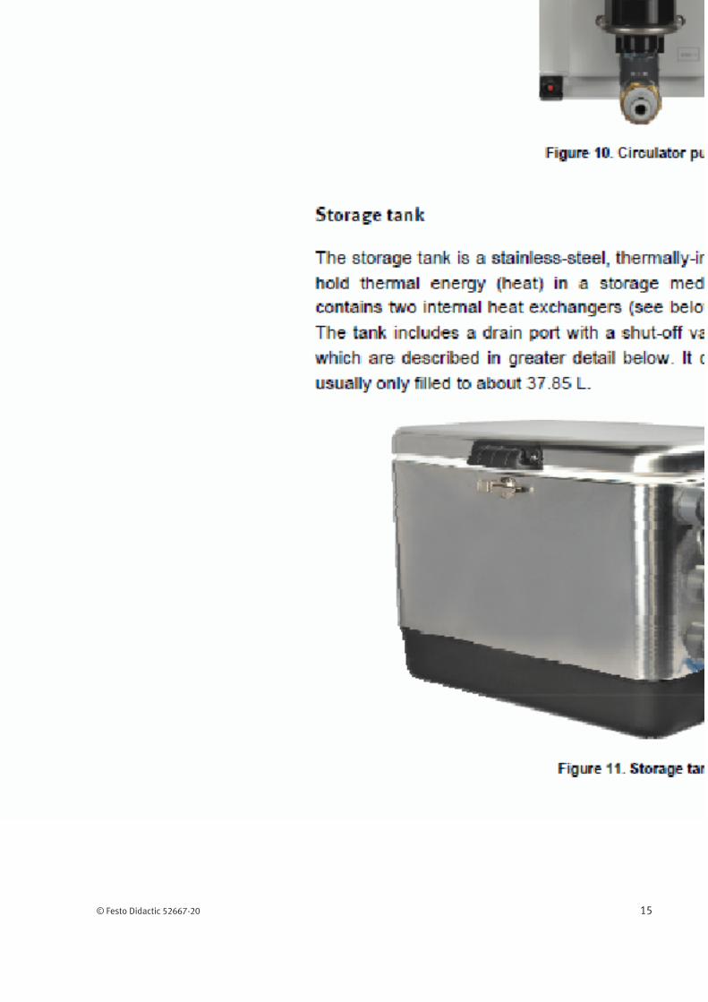
Tank return
The tank return is the hot water supply from the storage tank; however, it can also be used as a feed point in the system. The return is at the top of the storage tank.
Figure 13. Tank drain and return.
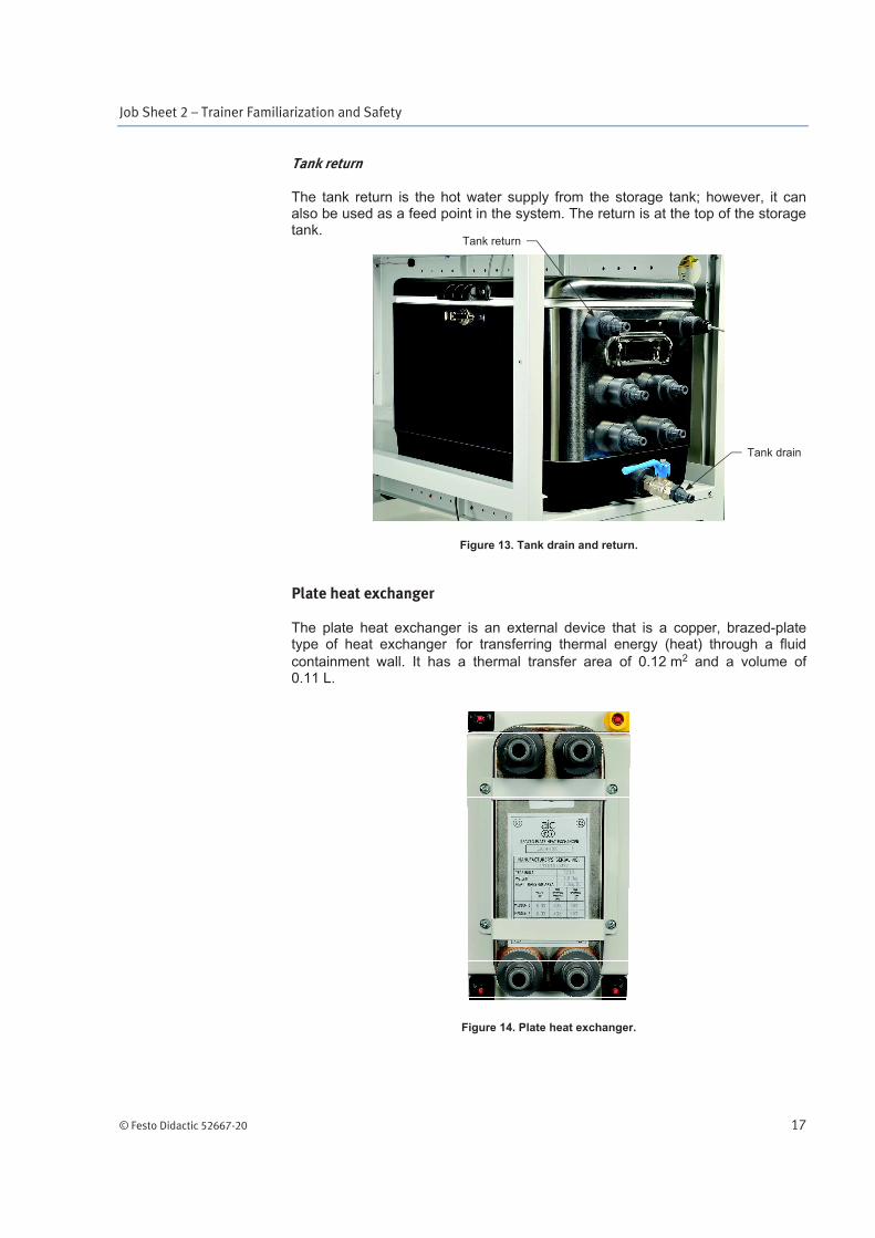
Plate heat exchanger
The plate heat exchanger is an external device that is a copper, brazed-plate type of heat exchanger for transferring thermal energy (heat) through a fluid
containment wall. It has a thermal transfer area of 0.12 m2 and a volume of 0.11 L.
Figure 14. Plate heat exchanger.
Tank return
Tank drain

Job Sheet 2 – Trainer Familiarization and Safety
18 © Festo Didactic 52667-20
Electrical panel
The electrical panel (Figure 15) includes an emergency switch, a circuit-breaker switch, a dc power source that connects to the radiator, an ac power outlet to which to the work lights connect, a thermostat controller, and a differential controller. Temperature sensors also connect to the electrical panel. The differential controller, the thermostat controller and the temperature sensors are described below.
Figure 15. The electrical panel.

Job Sheet 2 – Trainer Familiarization and Safety
© Festo Didactic 52667-20 19
Differential controller
The differential controller is a digital device for controlling circulators (pumps and blowers) that uses a difference in two temperatures to determine operating set points for its circulator. The differential temperature range can be set between 1.1°C and 22.22°C. The default set points are 6.67°C to turn the pump on, and 4.45°C to turn the pump off. The differential controller uses several remotely located 1000 (1 k ) platinum (Pt) resistance temperature detector (RTD) sensors. The two leftmost connectors (identified by numbers 1 and 2) are labelled “S1”, and are connected to the solar collector’s sensor. The two middle connectors (identified by numbers 3 and 4) are labelled “S2”, and are connected to the storage tank’s sensor. Finally, the two rightmost connectors (identified by numbers 7 and 8) are labelled “S4”, and are connected to the remote temperature sensor. The differential controller has a digital display and three push-button switches (“-”, “OK”, and “+”) to select various options. The controller and the pump are controlled by an override switch. When it is in the “Override” mode, the pump works independently from the controller settings. When the switch is in the “Off” mode, the pump is turned off. Finally, when the switch is in the “Controller” mode, the pump works according to the controller settings. A 4-pin connector is used to connect the controller to the pump. The differential controller is also called a temperature differential indicating controller (TDIC). It is rated for controlling an ac pump or relay.
Thermostat controller
The thermostat controller is an electromechanical switch for controlling a circulator (pump or blower) that uses a temperature threshold to activate or deactivate the circulator. This controller uses a remote sensing bulb with a fluid-filled capillary tube to detect temperature levels and trigger the switch as needed. The temperature set point is adjustable from 0°C to 40°C with a rotating knob and is compensated for ambient temperature. An internal single-pole, double-throw (SPDT) switch breaks contact (opens the circuit) when the temperature rises to the manually adjusted set point, and makes contact (closes the circuit) when the temperature falls 3.34°C below the set point. A 4-pin connector is used to connect the controller to the pump. The controller and the pump are controlled by an override switch. When it is in the “Override” mode, the pump works independently from the controller settings. When the switch is in the “Off” mode, the pump is turned off. Finally, when the switch is in the “Controller” mode, the pump works according to the controller settings.
Temperature sensors (3 electrical devices and 1 mechanical device)
Also called temperature detectors, the temperature sensors are specifically intended for use with the controllers provided in the training system.
Figure 16. Temperature sensor (RTD).

Job Sheet 2 – Trainer Familiarization and Safety
20 © Festo Didactic 52667-20
Figure 17. Electrical remote temperature sensor.
Figure 18. Mechanical remote temperature sensor.

Job Sheet 2 – Trainer Familiarization and Safety
© Festo Didactic 52667-20 21
Expansion tanks (2)
The expansion tanks are vessels that contain a flexible diaphragm and a pressurized secondary fluid (air) that permits the safe thermal expansion and contraction of its primary fluid (water). This fluid separation allows changes in primary fluid volume to occur that are directly related to primary fluid temperature changes. Each tank has a capacity of 7.95 L (maximum usable volume) and a maximum water capacity of 4.16 L. At ambient pressure, each tank can contain 50 mL of water, resulting in an air-side pressure of 248.21 kPa. In a closed loop circuit, a rise in the water temperature causes the water volume to increase above 50 mL. The maximum working pressure of the water side is 1000 kPa.
Figure 19. Expansion tank.
Job Sheet 2 – Trainer Familiarization and Safety
22 © Festo Didactic 52667-20
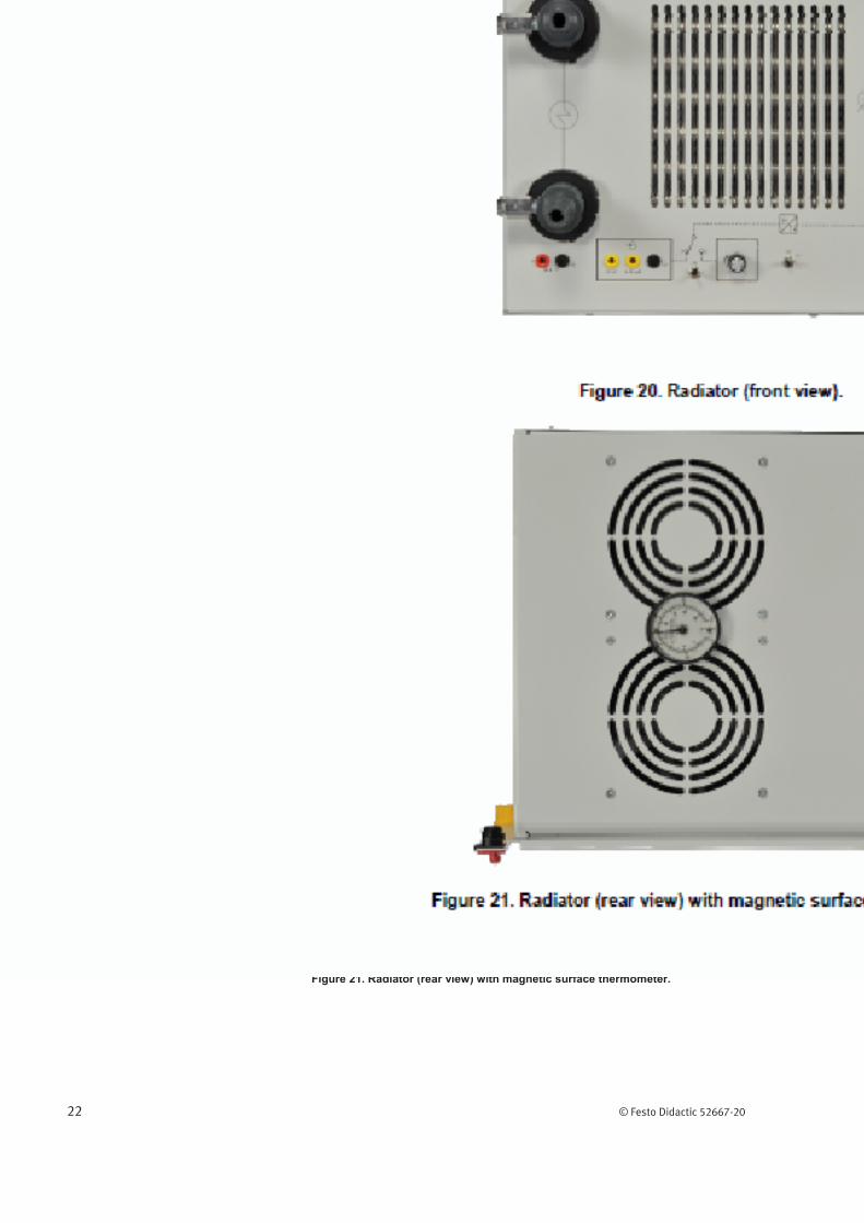
Radiator (with magnetic surface thermometer)
The radiator contains a 15.2 cm2 radiator core with a 1.06 m2 heat exchanger area to transfer thermal energy from water to air, and allows manual control of its blower speed for changing the air flow rate. The maximum air flow rate is 3000 L/min. The dual blower consists of two electric motors with fan blades powered by a 24 V dc, 2.4 A power supply output. The power supply input is rated appropriately for the ac power mains. A magnetic surface thermometer can be placed between the blower vents (slightly above the center) to monitor output temperature. Its measurement range is from -17.8°C to 65.6°C.
Figure 20. Radiator (front view).
Figure 21. Radiator (rear view) with magnetic surface thermometer.
Job Sheet 2 – Trainer Familiarization and Safety
© Festo Didactic 52667-20 23
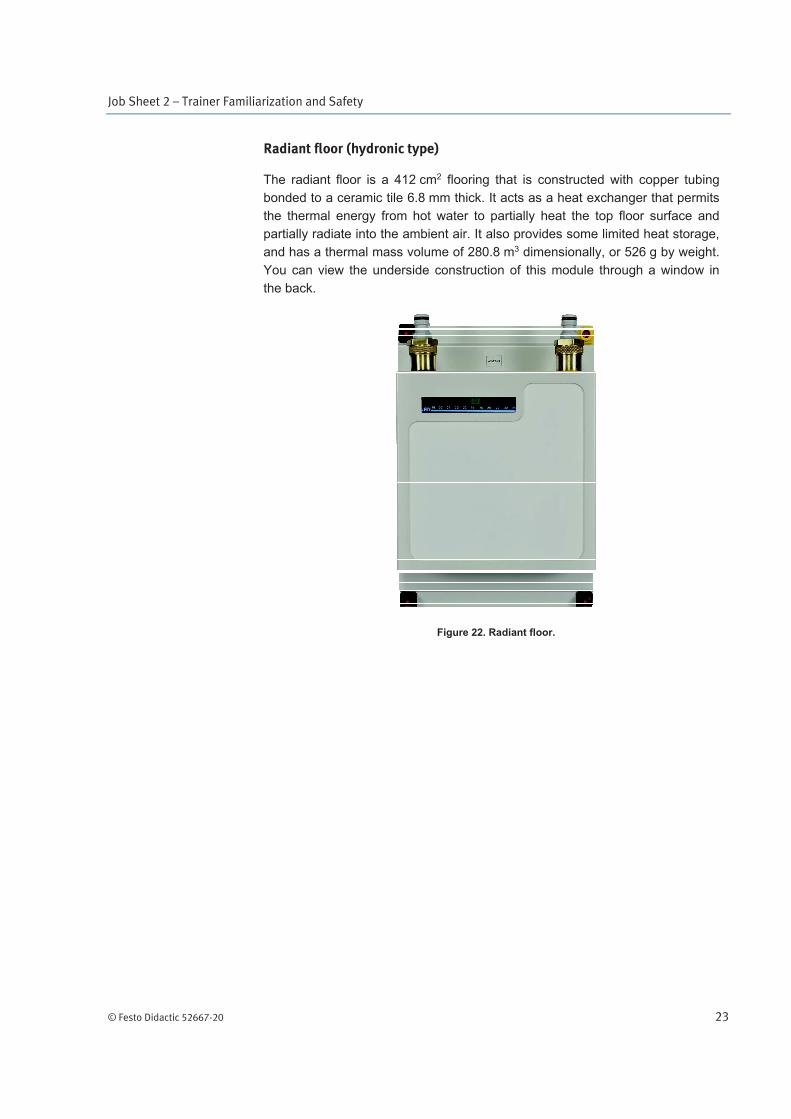
Radiant floor (hydronic type)
The radiant floor is a 412 cm2 flooring that is constructed with copper tubing
bonded to a ceramic tile 6.8 mm thick. It acts as a heat exchanger that permits
the thermal energy from hot water to partially heat the top floor surface and
partially radiate into the ambient air. It also provides some limited heat storage,
and has a thermal mass volume of 280.8 m3 dimensionally, or 526 g by weight.
You can view the underside construction of this module through a window in
the back.
Figure 22. Radiant floor.
Job Sheet 2 – Trainer Familiarization and Safety
24 © Festo Didactic 52667-20
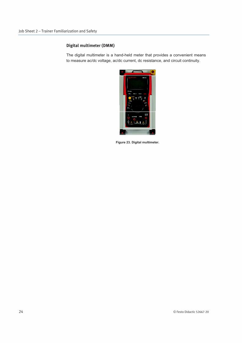
Digital multimeter (DMM)
The digital multimeter is a hand-held meter that provides a convenient means
to measure ac/dc voltage, ac/dc current, dc resistance, and circuit continuity.
Figure 23. Digital multimeter.

Job Sheet 2 – Trainer Familiarization and Safety
© Festo Didactic 52667-20 25
Thermometers (2)
The thermometers are analog meters that provide a quick indication of fluid temperature in degrees Celsius (°C) or Fahrenheit (°F). They use a coiled bimetallic strip to indicate the fluid temperature sensed in a brass immersion well. These devices also help to ensure that system fluid temperature ratings are not exceeded. Their measurement range is from 0°C to 121.1°C.
Never allow any of the system operating temperatures to exceed 50°C.
Figure 24. Thermometer.
Job Sheet 2 – Trainer Familiarization and Safety
26 © Festo Didactic 52667-20
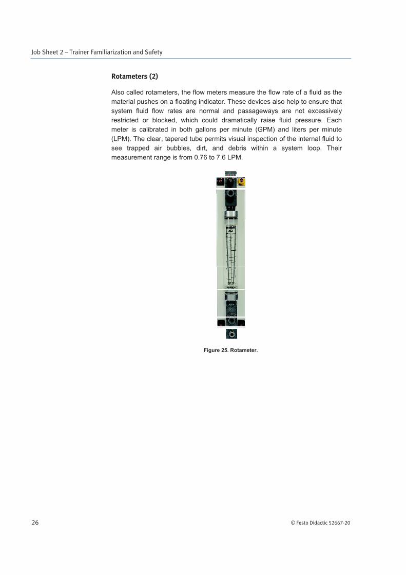
Rotameters (2)
Also called rotameters, the flow meters measure the flow rate of a fluid as the
material pushes on a floating indicator. These devices also help to ensure that
system fluid flow rates are normal and passageways are not excessively
restricted or blocked, which could dramatically raise fluid pressure. Each
meter is calibrated in both gallons per minute (GPM) and liters per minute
(LPM). The clear, tapered tube permits visual inspection of the internal fluid to
see trapped air bubbles, dirt, and debris within a system loop. Their
measurement range is from 0.76 to 7.6 LPM.
Figure 25. Rotameter.
Job Sheet 2 – Trainer Familiarization and Safety
© Festo Didactic 52667-20 27
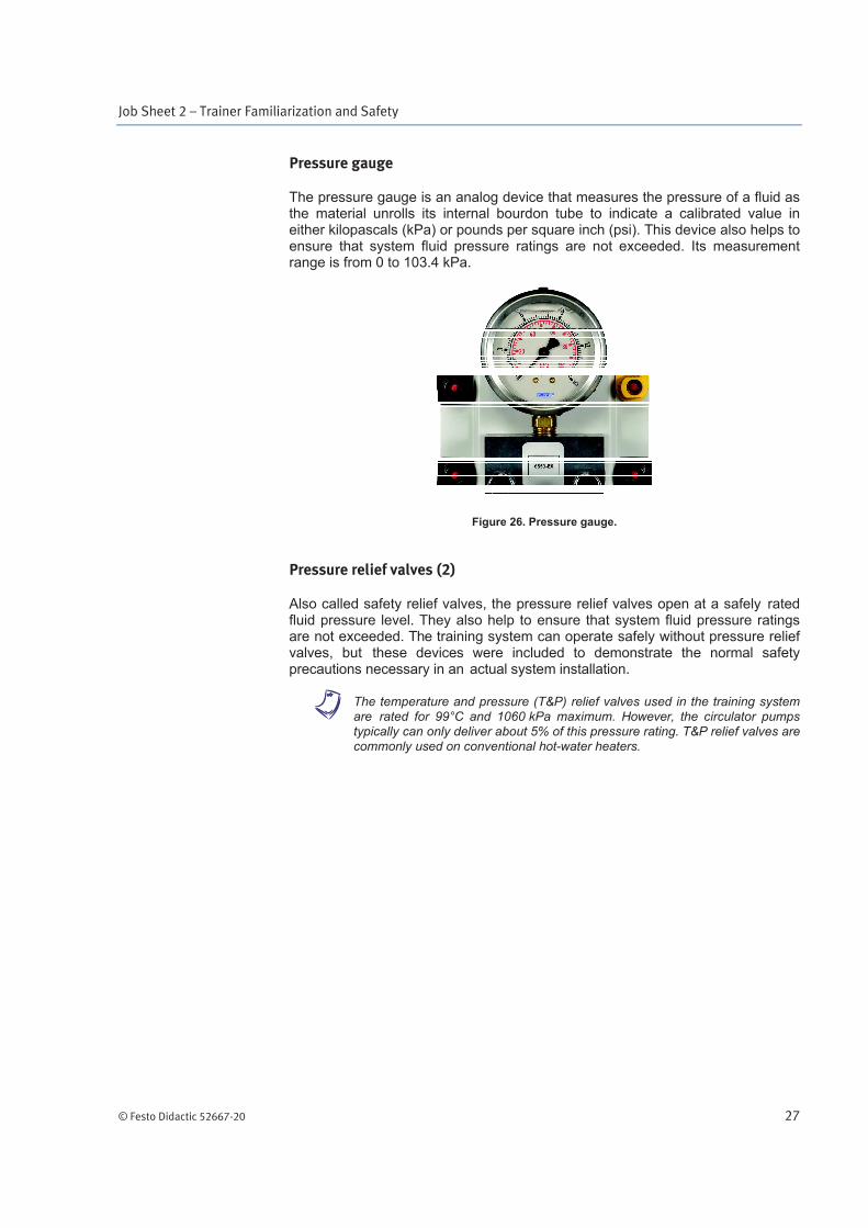
Pressure gauge
The pressure gauge is an analog device that measures the pressure of a fluid as the material unrolls its internal bourdon tube to indicate a calibrated value in either kilopascals (kPa) or pounds per square inch (psi). This device also helps to ensure that system fluid pressure ratings are not exceeded. Its measurement range is from 0 to 103.4 kPa.
Figure 26. Pressure gauge.
Pressure relief valves (2)
Also called safety relief valves, the pressure relief valves open at a safely rated fluid pressure level. They also help to ensure that system fluid pressure ratings are not exceeded. The training system can operate safely without pressure relief valves, but these devices were included to demonstrate the normal safety precautions necessary in an actual system installation.
a The temperature and pressure (T&P) relief valves used in the training system are rated for 99°C and 1060 kPa maximum. However, the circulator pumps typically can only deliver about 5% of this pressure rating. T&P relief valves are commonly used on conventional hot-water heaters.

Job Sheet 2 – Trainer Familiarization and Safety
28 © Festo Didactic 52667-20
Discharge lines (2)
The discharge lines are tubes or pipes that safely redirect fluid as it is expelled from a relief valve.
Figure 27. Discharge line and pressure relief valve.
Shutoff valves (2)
The shutoff valves are manually operated devices for controlling fluid flow in an on or off fashion. These devices can also help to ensure that a system component is safely isolated from other parts of the system when necessary.
Figure 28. Shutoff valve.
Pressure reliefvalve
Discharge line

Job Sheet 2 – Trainer Familiarization and Safety
© Festo Didactic 52667-20 29
Check valve (swing gate type)
Also called a flow check valve or non-return valve, the check valve is an automatic device for controlling fluid flow in only one direction, as indicated on the device.
This device also helps to ensure that system fluid travels in only one direction to maintain safe operating conditions. It should not be positioned pointing in a downward direction. Check valves are often used in solar loops to prevent thermosiphoning.
Drain valves (2)
The drain valves are two boiler drain valves that are part of the check valve assembly, and can be used to fill, drain, or purge the system.
Figure 29. Check valve assembly.
Drain valve
Check valve
Job Sheet 2 – Trainer Familiarization and Safety
30 © Festo Didactic 52667-20
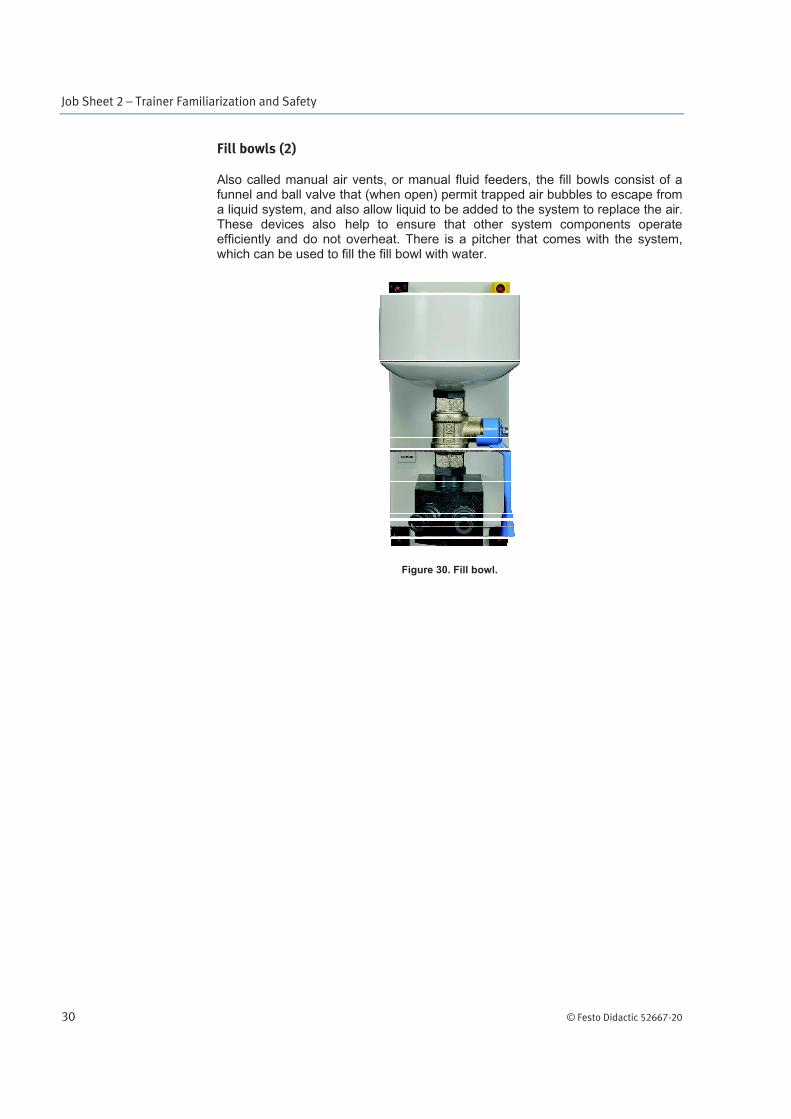
Fill bowls (2)
Also called manual air vents, or manual fluid feeders, the fill bowls consist of a funnel and ball valve that (when open) permit trapped air bubbles to escape from a liquid system, and also allow liquid to be added to the system to replace the air. These devices also help to ensure that other system components operate efficiently and do not overheat. There is a pitcher that comes with the system, which can be used to fill the fill bowl with water.
Figure 30. Fill bowl.
Job Sheet 2 – Trainer Familiarization and Safety
© Festo Didactic 52667-20 31
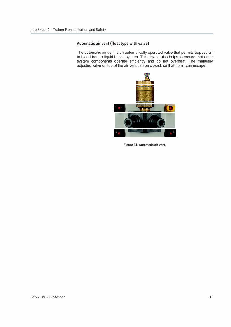
Automatic air vent (float type with valve)
The automatic air vent is an automatically operated valve that permits trapped air to bleed from a liquid-based system. This device also helps to ensure that other system components operate efficiently and do not overheat. The manually adjusted valve on top of the air vent can be closed, so that no air can escape.
Figure 31. Automatic air vent.

Job Sheet 2 – Trainer Familiarization and Safety
32 © Festo Didactic 52667-20
Dual work light
The dual work light contains two 500 W lamps for a total of 1 kW (2 lamps) that are powered by the AC mains. These two lamps are intended to be directed at the solar collector with their light evenly distributed to simulate radiant energy from the sun.
Figure 32. Dual work light.

Job Sheet 2 – Trainer Familiarization and Safety
© Festo Didactic 52667-20 33
Tubing kit (assortment of 30.48 cm, 60.96 cm, 91.44 cm, and 182.88 cm lengths)
The tubing kit is an assortment of pre-fabricated vinyl interconnection hoses that are included with the trainer and feature special one-way valves at each end to help prevent accidental system draining. The hoses are kept inside a white case, as shown on Figure 34.
Figure 33. Hoses (from tubing kit).
Figure 34. Case containing the hoses.
Other useful tools and materials that may be needed, include the following:
Shop vac: to remove water from drip pan.
Bucket and mop: these handy items can be helpful to clean up minor water spills in order to avoid water damage to the work area and to help prevent accidental slipping.
Towels: cloth towels or a roll of paper towels can be used to dry hands and equipment surfaces.
Job Sheet 2 – Trainer Familiarization and Safety
34 © Festo Didactic 52667-20
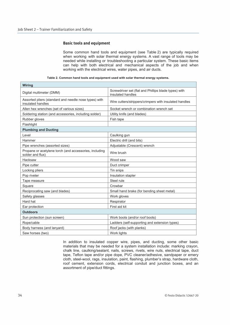
Basic tools and equipment
Some common hand tools and equipment (see Table 2) are typically required when working with solar thermal energy systems. A vast range of tools may be needed while installing or troubleshooting a particular system. These basic items can help with both electrical and mechanical aspects of the job and when working with the electrical wires, water pipes, and air ducts.
Table 2. Common hand tools and equipment used with solar thermal energy systems.
Wiring
Digital multimeter (DMM) Screwdriver set (flat and Phillips blade types) with insulated handles
Assorted pliers (standard and needle nose types) with insulated handles
Wire cutters/strippers/crimpers with insulated handles
Allen hex wrenches (set of various sizes) Socket wrench or combination wrench set
Soldering station (and accessories, including solder) Utility knife (and blades)
Rubber gloves Fish tape
Flashlight
Plumbing and Ducting
Level Caulking gun
Hammer Electric drill (and bits)
Pipe wrenches (assorted sizes) Adjustable (Crescent) wrench
Propane or acetylene torch (and accessories, including solder and flux)
Wire brush
Hacksaw Wood saw
Pipe cutter Duct crimper
Locking pliers Tin snips
Pop riveter Insulation stapler
Tape measure Steel rule
Square Crowbar
Reciprocating saw (and blades) Small hand brake (for bending sheet metal)
Safety glasses Work gloves
Hard hat Respirator
Ear protection First aid kit
Outdoors
Sun protection (sun screen) Work boots (and/or roof boots)
Rope/cable Ladders (self-supporting and extension types)
Body harness (and lanyard) Roof jacks (with planks)
Saw horses (two) Work lights
In addition to insulated copper wire, pipes, and ducting, some other basic materials that may be needed for a system installation include: marking crayon, chalk line, caulking/sealant, nails, screws, rivets, wire nuts, electrical tape, duct tape, Teflon tape and/or pipe dope, PVC cleaner/adhesive, sandpaper or emery cloth, steel-wool, rags, insulation, paint, flashing, plumber’s strap, hardware cloth, roof cement, extension cords, electrical conduit and junction boxes, and an assortment of pipe/duct fittings.
Job Sheet 2 – Trainer Familiarization and Safety
© Festo Didactic 52667-20 35
Basic safety practices
As with any electrical and/or mechanical equipment, there are inherent dangers. Alternative energy systems can involve devices in motion (turbines and motors), high voltages (inverter output and utility grid), and other hazards (scalding hot water). Serious injuries can occur if the following basic safety recommendations are not followed correctly.
a While this job covers some basic safety steps, it is not intended to replace a complete industrial safety training program.
Whenever installing, operating, servicing, or maintaining equipment, local and national building, fire and electrical codes must be followed to ensure a safe system and environment.
Equipment manufacturers normally supply manuals (or other documentation) with installation recommendations that should be followed to ensure safe operation. Recommended safe practices for specific equipment during service or maintenance are usually provided by the manufacturers, as well.
While servicing or maintaining machines and equipment, it is vitally important for you to stay alert and be aware of any potential conditions that may cause physical injury, such as slipping, tripping, or electrical shock. The proper use of tools is also vitally important for safety. For example, a knife blade should never be used as a replacement for a screwdriver.
While performing work, you can keep the equipment, yourself, other people, and your environment protected by applying some of the simple safety measures that are outlined here. Safety is a primary objective to being successful on the job. You should strive to continually develop safe work habits.
Clothing and personal protective equipment
Wearing appropriate clothes and protective equipment is essential to limit the
risk of injury, but it is also important to bear in mind that protective equipment
is not a substitute for good work practices.
Always make sure that the clothes you are wearing cannot get caught in
rotating equipment. Ties, jewelry, watches, and loose clothing must be
avoided. If you are wearing a jacket with long sleeves, always roll the sleeves
up.
Always wear safety glasses and protective shoes. Remember that many
injuries result from wearing improper or poorly fitting protective equipment.
When wearing gloves to perform a task, always make sure that the gloves
cannot get caught in rotating equipment.
If your hair is long, tie it out of the way before using rotating equipment.

Job Sheet 2 – Trainer Familiarization and Safety
36 © Festo Didactic 52667-20
Working environment
Installation and maintenance operations require a safe working environment.
Keep the working environment clean, orderly, and free of debris and other
obstructions such as tools and loose parts.
Floors should be clean and free of oil to ensure good footing and balance.
Always keep hazardous machines and equipment properly guarded when in
operation.

© Festo Didactic 52667-20 37
In this job, you will become familiar with the solar thermal training system and the associated hardware that is required to properly install a solar thermal energy system. You will also apply some basic safety practices before beginning and while performing the work.
Equipment required
Refer to the Equipment Utilization Chart in Appendix A to obtain the list of equipment required for this job.
Safety procedures
Before proceeding with this job, complete the following checklist.
You are wearing safety glasses.
You are wearing safety shoes.
You are not wearing anything that might get caught such as a tie,
jewelry, or loose clothes.
If your hair is long, tie it out of the way.
The working area is clean and free of oil.
The floor is not wet.
Your sleeves are rolled up.
The wheels of the system are locked in place.
System components
1. Locate and inspect the following items on the trainer. Check off each item in the list below as you complete this step for each component in the training system.
Mobile workstation (trainer frame and assembly)
Solar collector
Circulator pumps (2)
Storage tank (with 2 heat exchangers)
Plate heat exchanger
Differential controller (with 3 sensors)
Trainer Familiarization and Safety
Job Sheet 2
OBJECTIVE
PROCEDURE
Job Sheet 2 – Trainer Familiarization and Safety
38 © Festo Didactic 52667-20
Thermostat controller (with 1 sensor)
Expansion tanks (2)
Radiator (with magnetic surface thermometer)
Radiant floor
Digital multimeter (DMM)
Thermometers (2)
Rotameters (2)
Pressure gauge
Pressure relief valves (2)
Discharge lines (2)
Shutoff valves (2)
Check valve assembly (with 2 drain valves)
Fill bowls (2)
Automatic air vent
Collector inlet (with shutoff valve)
Collector outlet
Tank drain (with shutoff valve)
Tank return
Electrical panel
Dual work light
Tubing kit (assortment of 30.48 cm, 60.96 cm, 91.44 cm, and 182.88 cm
lengths)
Water can
Bucket and mop
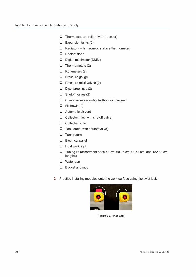
2. Practice installing modules onto the work surface using the twist lock.
Figure 35. Twist lock.

Job Sheet 2 – Trainer Familiarization and Safety
© Festo Didactic 52667-20 39
3. List at least two modules that you tried to install and lock.
4. Were you able to install and lock the modules successfully?
Yes No
5. If you are having trouble locking any of the modules, ask your instructor for assistance.
6. Practice connecting a hose between two different modules while making sure that each hose connector is seated and locked securely.
7. Were you able to connect a hose properly?
Yes No
8. If you are having trouble connecting any of the hoses, ask your instructor for assistance.
9. Ask the instructor to check your work.
Name: ______________________________ Date: ____________________
Instructor's approval: ______________________________________________