Embed Size (px)
Citation preview

SMART DVB PRO Familiarization
SMART DVB PRO Familiarization
E-mail: [email protected]
Web: www.dualz-solutions.nl
SMART DVB PRO FAMILIARIZATION SMART SUITE

WARNING: TO REDUCE THE RISK OF FIRE OR
ELECTRICAL SHOCK, DO NOT EXPOSE THIS
APPLIANCE TO RAIN OR MOISTURE
● ALWAYS disconnect your entire system from the AC mains before cleaning any component.
● NEVER use flammable or combustible chemicals for cleaning components.
● NEVER operate this product if any cover is removed.
● NEVER wet the inside of this product with any liquid.
● NEVER pour or spill liquids directly onto this unit.
● NEVER block airflow through ventilation slots.
● NEVER bypass any fuse.
● NEVER replace any fuse with a value or type other than those specified.
● NEVER attempt to repair this product. If a problem occurs, contact your local Dualz Solutions
distributor.
● NEVER expose this product to extremely high or low temperatures.
● NEVER operate this product in an explosive atmosphere.
Warranty: Dualz Solutions warrants their products according to the warranty policy as described in the
general terms. That means that Dualz Solutions BV can only warrant the products as long as the serial
numbers are not removed.
Copyright © 2019 Dualz Solutions B.V.
Date created: 07-10-2014
Date last revised: 23-7-2019
This product complies with the requirements of the product family standards for audio, video, audio-
visual entertainment lighting control apparatus for professional use as mentioned below.
EN60950
EN55103-1: 1996
EN55103-2: 1996
Safety
Emission
Immunity
Page 4 of 86
SMART DVB PRO Familiarization
Dualz Solutions
Tested To Comply
With FCC Standards
1 FOR HOME OR OFFICE
USE
This device complies with part 15 of the FCC Rules
Operation is subject to the following two conditions:
(1) This device may cause harmful interference, and
(2) This device must accept any interference received,
including interference that may cause undesired operation.
Page 5 of 86
SMART DVB PRO Familiarization
Contents 1 FOR HOME OR OFFICE USE ................................................................................. 4
Document approval .............................................................................................. 8 2 Setting up the Dualz Solutions SMART server(s) .................................................... 9
2.1 The SMART 10/25 Probe front view ............................................................... 9 2.2 The SMART 10/25 Probe rear view* .............................................................. 9 2.3 The SMART 50, 80 & 90 Probe front view ....................................................... 9 2.4 The SMART 50, 80 & 90 Probe Rear view ...................................................... 10 2.5 The SMART 90 XL Probe front view ............................................................... 10 2.6 The SMART 90 XL Probe Rear view ............................................................... 11 2.7 The SMART Gateway Front view ................................................................... 11 2.8 SMART Gateway Rear view .......................................................................... 11
3 Setting display Monitor(s) .................................................................................. 13 4 Network connectivity and scalability .................................................................... 14
4.1 The Management connection ....................................................................... 14 5 Switch the system on and off ............................................................................. 15
5.1 Switching on the Dualz Solutions SMART Probe .............................................. 15 5.2 Switching off the Dualz Solutions SMART Probe ............................................. 15
6 Load and save the Probe configuration ................................................................ 16 6.1 Loading an existing configuration ................................................................. 16 6.2 Saving a configuration ................................................................................ 17
7 Run and Configuration mode .............................................................................. 18 8 The Alarm template editor ................................................................................. 20 9 Add and Remove an IP or ASI transport stream to the Probe.................................. 23
9.1 Adding and removing an IP transport stream ................................................. 23 9.2 Adding and removing an ASI transport stream ............................................... 25 9.3 Adding SPTS IP streams.............................................................................. 26
10 Start and stop analysing services .................................................................... 27 11 Explanation of the Probe tree ......................................................................... 30 12 Basic monitoring views .................................................................................. 32
12.1 TR290 view ............................................................................................... 32 12.2 Viewing EPG information in the Transport Stream .......................................... 32
13 Probe Settings Menu...................................................................................... 34 13.1 System Settings ........................................................................................ 34
13.1.1 Colors ................................................................................................ 35
13.1.2 SNMP ................................................................................................. 35
13.1.3 Monitors ............................................................................................. 35
13.1.4 Triggered recordings (option only) ......................................................... 35
13.1.5 Alarm actions ...................................................................................... 35
14 Multi-viewer configurator ............................................................................... 37 14.1 Generic Multi-viewer settings ....................................................................... 37 14.2 Multi-viewer Pre-set configuration ................................................................ 38 14.3 Menu ........................................................................................................ 39
14.3.1 File .................................................................................................... 39
14.3.2 Edit .................................................................................................... 41
14.3.3 View ................................................................................................... 41
14.4 Multi-viewer entities ................................................................................... 41 14.4.1 Multi-viewer Full Size Service popup.** .................................................. 42
14.5 Display Settings ......................................................................................... 44 14.6 Adding manual “Display” ............................................................................. 46
Page 6 of 86
SMART DVB PRO Familiarization
14.7 Adding some multiviewer entities (attributes) ................................................ 47 14.7.1 Adding a clock ..................................................................................... 47
14.7.2 Transport Panel (TS) ............................................................................ 49
14.7.3 Display CPU and Mem points ................................................................. 51
14.8 Closing down the Multi-viewer Pre-set editor ................................................. 52 14.9 Service Mapping ........................................................................................ 53 14.10 Show Display selecting ............................................................................ 54
14.10.1 Multichannel audio decoding ............................................................... 55
15 ACC Setup for Probe connection ...................................................................... 56 15.1 Preconditions on the Probe .......................................................................... 56 15.2 Preconditions on the ACC ............................................................................ 57
15.2.1 Set communication interface and port .................................................... 57
15.2.2 Add probes ......................................................................................... 57
15.3 ACC User NOC Interface ............................................................................. 58 15.3.1 TS Button View .................................................................................... 58
15.3.2 Current Alarm View .............................................................................. 58
15.3.3 History View ........................................................................................ 58
15.4 ACC connection with the Probe(s) ................................................................ 59 15.4.1 Probe Views within the ACC ................................................................... 59
15.4.2 Tab “Server” ....................................................................................... 59
15.4.3 Tab “Colors” ........................................................................................ 59
15.4.4 Tab “Logging” ...................................................................................... 61
15.4.5 Tab “Email” ......................................................................................... 61
15.4.6 Tab “Bitrate reports” ............................................................................ 62
15.4.7 Tab “Availability reports” ...................................................................... 63
15.5 Set Run/Config mode via ACC ...................................................................... 64 16 SoloControl .................................................................................................. 66 17 Multi-viewer (New version) ............................................................................. 68
17.1 General Multi-viewer explanation ................................................................. 68 17.2 Multi-viewer .............................................................................................. 68
17.2.1 Configure the Multi-viewer .................................................................... 69
17.2.2 File menu: .......................................................................................... 69
17.2.3 Edit Menu: .......................................................................................... 70
17.2.4 View: ................................................................................................. 70
17.2.5 Display CPU and Mem points ................................................................. 70
17.3 Closing down the Multi-viewer Pre-set editor ................................................. 71 17.3.1 Default building setting: ....................................................................... 72
17.3.2 Tree view of selectable Services and attributes ........................................ 72
17.3.3 Hide selected Services .......................................................................... 73
17.4 How build a quad split Multi-viewer .............................................................. 73 17.5 Adjusting the Multi-viewer display settings. ................................................... 75
17.5.1 To customize settings in the Multi-viewer some settings: .......................... 75
17.5.2 CPU/GPU selector................................................................................. 76
Page 7 of 86
SMART DVB PRO Familiarization
18 Examples of Single/dual screens setup 80/90/90XL ........................................... 77 18.1 SMART DVB 100 display setup ..................................................................... 79
19 DVB Tables .................................................................................................. 82 19.1 Table ID values .......................................................................................... 82 19.2 Valid PIDs ................................................................................................. 82
19 Tables and descriptors Described in more detail below ........................................... 83 19.1 Program Association Table (PAT).................................................................. 83 19.2 Program Map Table (PMT) ........................................................................... 83 19.3 Conditional Access Table (CAT) .................................................................... 83 19.4 Network Information Table (NIT) ................................................................. 83 19.5 Service Description Table (SDT) ................................................................... 83 19.6 Event Information Table (EIT) ..................................................................... 83 19.7 Time and Date Table (TDT) ......................................................................... 84 19.8 Bouquet Association Table (BAT) .................................................................. 84 19.9 Time Offset Table (TOT).............................................................................. 84
20 Definitions, Acronyms and abbreviations .......................................................... 85
Page 8 of 86
SMART DVB PRO Familiarization
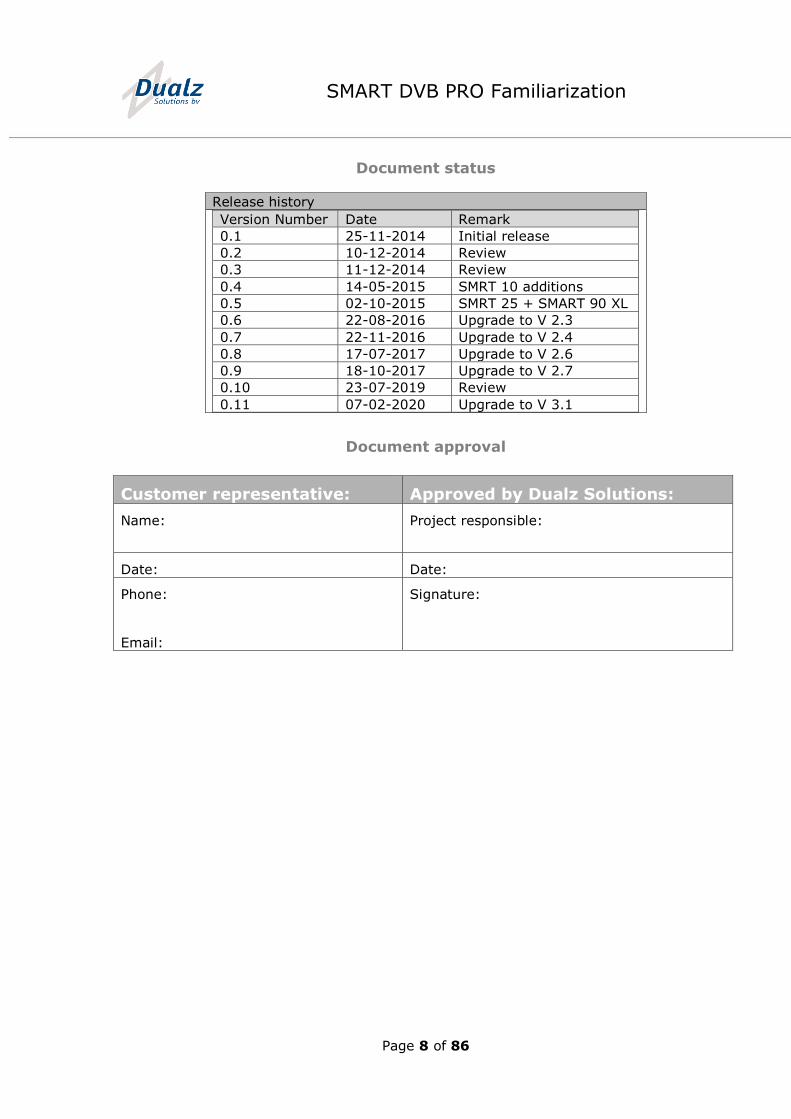
Document status
Release history
Version Number Date Remark
0.1 25-11-2014 Initial release
0.2 10-12-2014 Review
0.3 11-12-2014 Review
0.4 14-05-2015 SMRT 10 additions
0.5 02-10-2015 SMRT 25 + SMART 90 XL
0.6 22-08-2016 Upgrade to V 2.3
0.7 22-11-2016 Upgrade to V 2.4
0.8 17-07-2017 Upgrade to V 2.6
0.9 18-10-2017 Upgrade to V 2.7
0.10 23-07-2019 Review
0.11 07-02-2020 Upgrade to V 3.1
Document approval
Customer representative: Approved by Dualz Solutions:
Name:
Project responsible:
Date: Date:
Phone:
Email:
Signature:
Page 9 of 86
SMART DVB PRO Familiarization
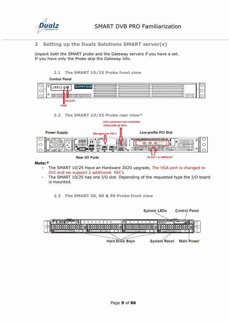
2 Setting up the Dualz Solutions SMART server(s)
Unpack both the SMART probe and the Gateway servers if you have a set.
If you have only the Probe skip the Gateway info.
2.1 The SMART 10/25 Probe front view
2.2 The SMART 10/25 Probe rear view*
Note:*
- The SMART 10/25 Have an Hardware 2020 upgrade, The VGA port is changed to
DVI and we support 2 additional NIC’s
- The SMART 10/25 has one I/O slot. Depending of the requested type the I/O board
is mounted.
2.3 The SMART 50, 80 & 90 Probe front view
Page 10 of 86
SMART DVB PRO Familiarization
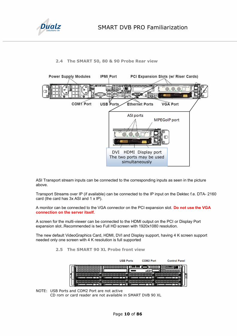
2.4 The SMART 50, 80 & 90 Probe Rear view
ASI Transport stream inputs can be connected to the corresponding inputs as seen in the picture above. Transport Streams over IP (if available) can be connected to the IP input on the Dektec f.e. DTA- 2160 card (the card has 3x ASI and 1 x IP). A monitor can be connected to the VGA connector on the PCI expansion slot. Do not use the VGA connection on the server itself. A screen for the multi-viewer can be connected to the HDMI output on the PCI or Display Port expansion slot..Recommended is two Full HD screen with 1920x1080 resolution. The new default VideoGraphics Card, HDMI, DVI and Display support, having 4 K screen support needed only one screen with 4 K resolution is full supported
2.5 The SMART 90 XL Probe front view
NOTE: USB Ports and COM2 Port are not active CD rom or card reader are not available in SMART DVB 90 XL
DVI HDMI Display port
The two ports may be used simultaneously
Page 11 of 86
SMART DVB PRO Familiarization
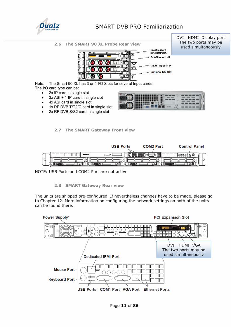
2.6 The SMART 90 XL Probe Rear view
Note: The Smart 90 XL has 3 or 4 I/O Slots for several Input cards. The I/O card type can be:
2x IP card in single slot
3x ASI + 1 IP card in single slot
4x ASI card in single slot
1x RF DVB T/T2/C card in single slot
2x RF DVB S/S2 card in single slot
2.7 The SMART Gateway Front view
NOTE: USB Ports and COM2 Port are not active
2.8 SMART Gateway Rear view
The units are shipped pre-configured. If nevertheless changes have to be made, please go to Chapter 12. More information on configuring the network settings on both of the units
can be found there.
DVI HDMI VGA The two ports may be
used simultaneously
DVI HDMI Display port The two ports may be
used simultaneously
Page 12 of 86
SMART DVB PRO Familiarization
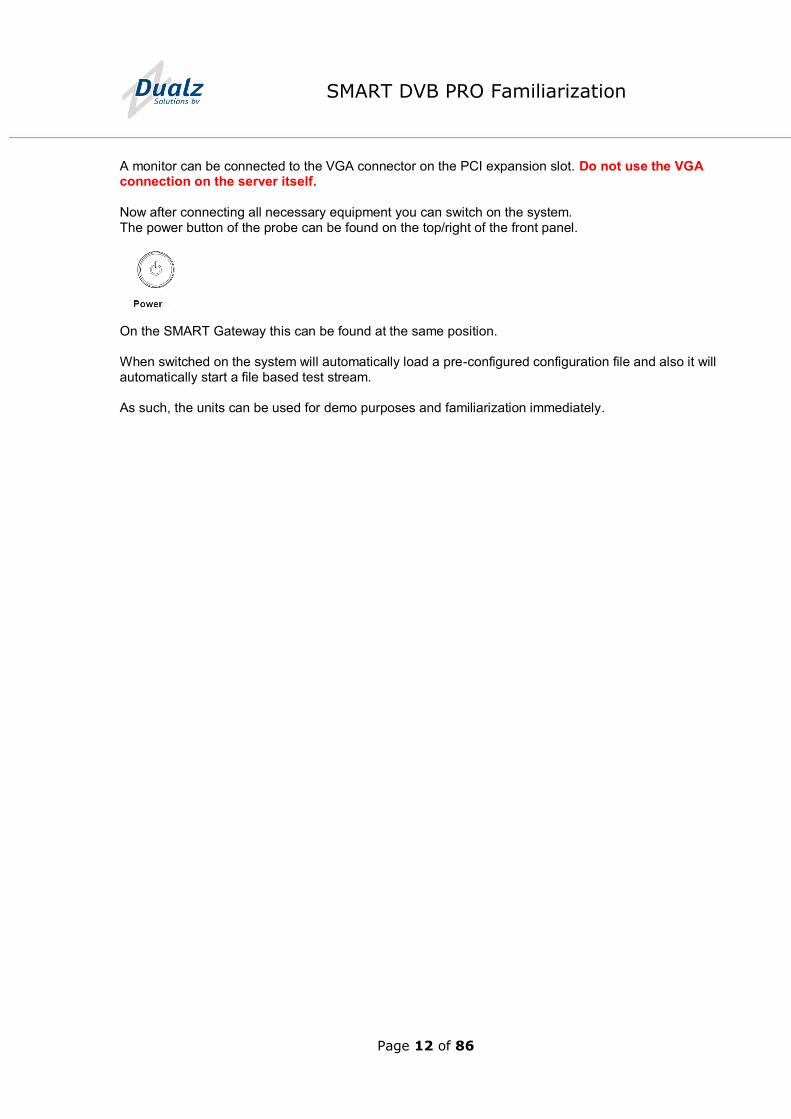
A monitor can be connected to the VGA connector on the PCI expansion slot. Do not use the VGA connection on the server itself.
Now after connecting all necessary equipment you can switch on the system. The power button of the probe can be found on the top/right of the front panel.
On the SMART Gateway this can be found at the same position. When switched on the system will automatically load a pre-configured configuration file and also it will automatically start a file based test stream. As such, the units can be used for demo purposes and familiarization immediately.
Page 13 of 86
SMART DVB PRO Familiarization
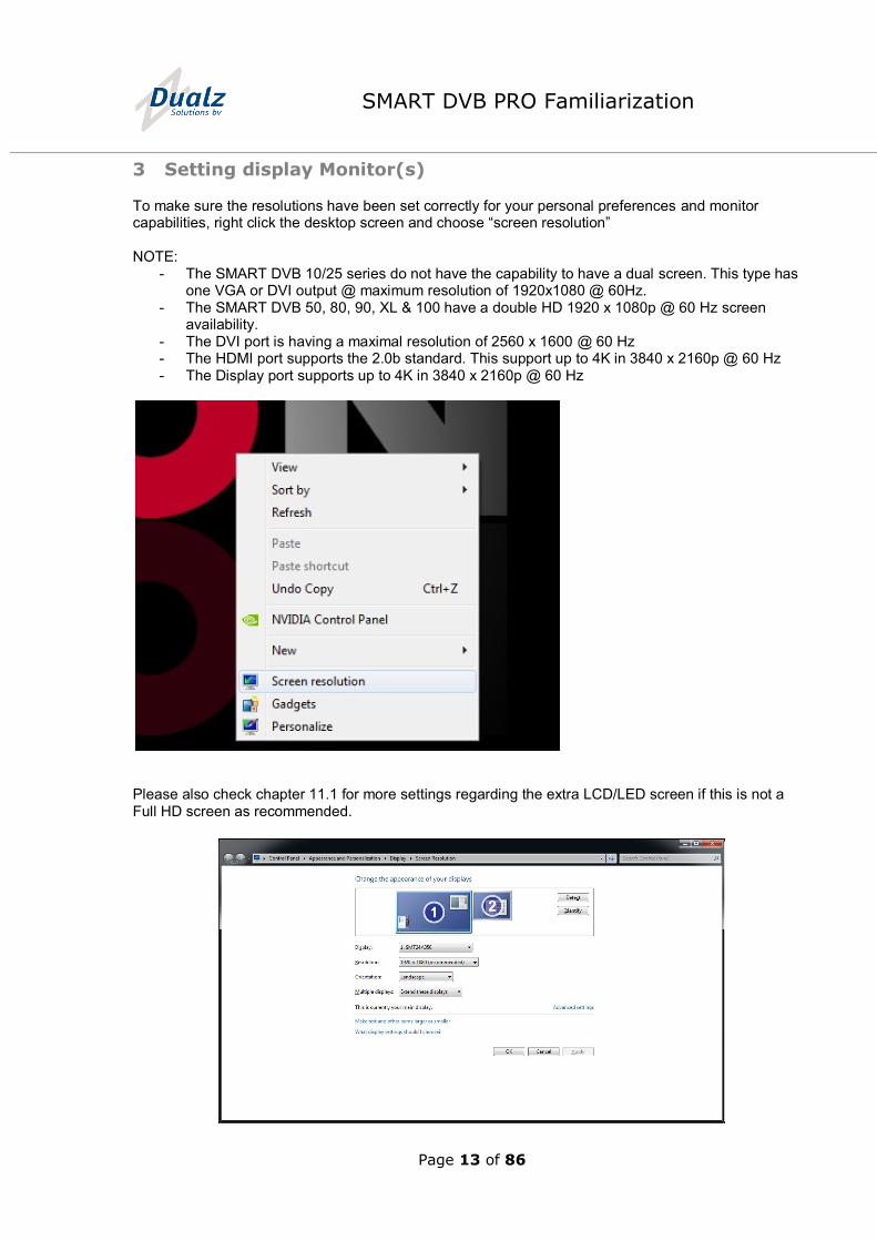
3 Setting display Monitor(s)
To make sure the resolutions have been set correctly for your personal preferences and monitor capabilities, right click the desktop screen and choose “screen resolution” NOTE:
- The SMART DVB 10/25 series do not have the capability to have a dual screen. This type has one VGA or DVI output @ maximum resolution of 1920x1080 @ 60Hz.
- The SMART DVB 50, 80, 90, XL & 100 have a double HD 1920 x 1080p @ 60 Hz screen availability.
- The DVI port is having a maximal resolution of 2560 x 1600 @ 60 Hz - The HDMI port supports the 2.0b standard. This support up to 4K in 3840 x 2160p @ 60 Hz - The Display port supports up to 4K in 3840 x 2160p @ 60 Hz
Please also check chapter 11.1 for more settings regarding the extra LCD/LED screen if this is not a Full HD screen as recommended.
Page 14 of 86
SMART DVB PRO Familiarization
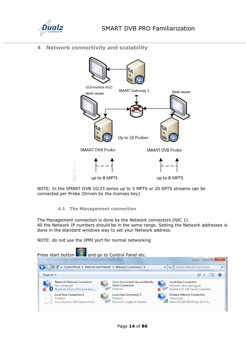
4 Network connectivity and scalability
NOTE: In the SMART DVB 10/25 series up to 3 MPTS or 20 SPTS streams can be
connected per Probe (Driven by the licenses key)
4.1 The Management connection
The Management connection is done by the Network connectors (NIC 1).
All the Network IP numbers should be in the same range. Setting the Network addresses is
done in the standard windows way to set your Network address.
NOTE: do not use the IPMI port for normal networking
Press start button and go to Control Panel etc.
Page 15 of 86
SMART DVB PRO Familiarization
5 Switch the system on and off
5.1 Switching on the Dualz Solutions SMART Probe
When switching on the power of the server, the watchdog application will start the SMART
Probe software automatically (default setup).
5.2 Switching off the Dualz Solutions SMART Probe
When switching off the Probe manually, please do this as described below.
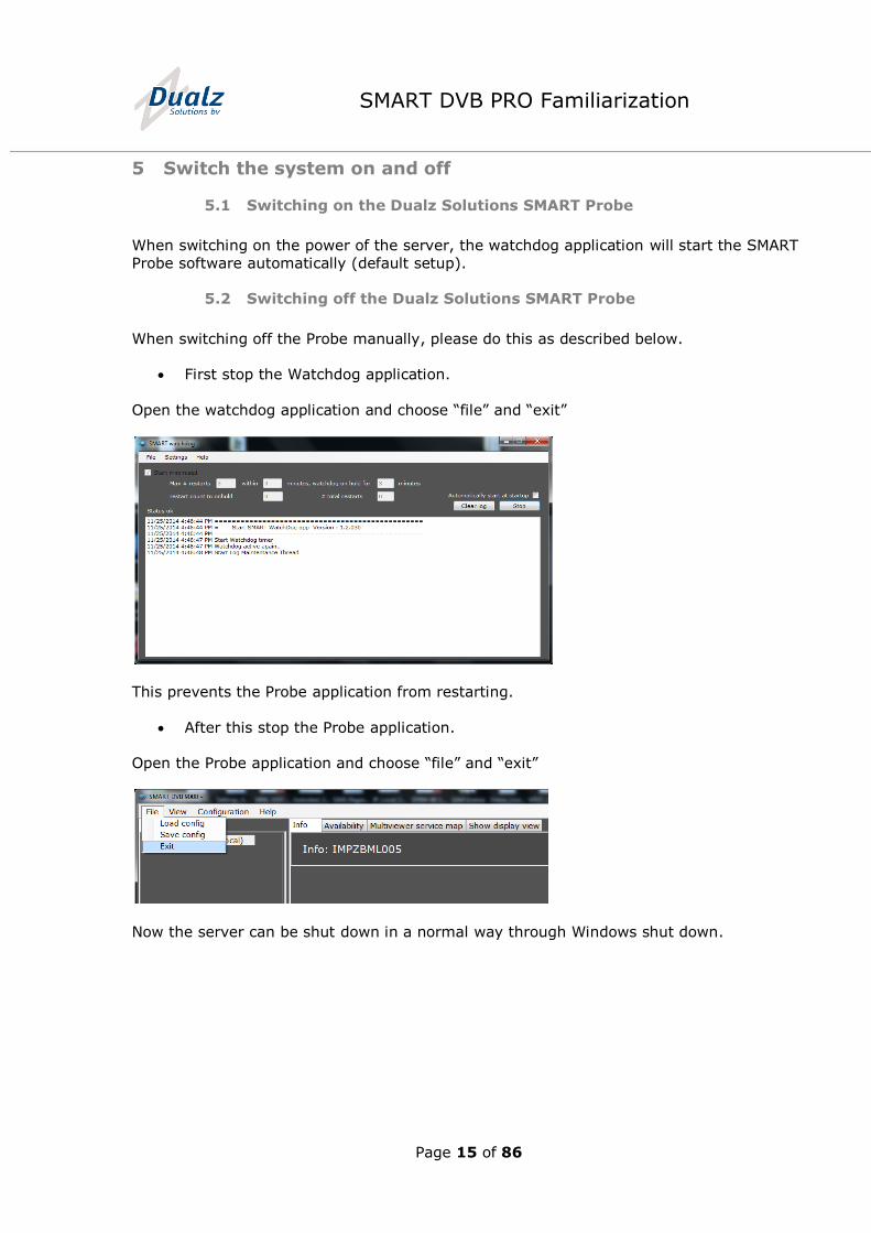
First stop the Watchdog application.
Open the watchdog application and choose “file” and “exit”
This prevents the Probe application from restarting.
After this stop the Probe application.
Open the Probe application and choose “file” and “exit”
Now the server can be shut down in a normal way through Windows shut down.
Page 16 of 86
SMART DVB PRO Familiarization
6 Load and save the Probe configuration
6.1 Loading an existing configuration
To load a configuration there are two options.
Manual loading
Automatic loading
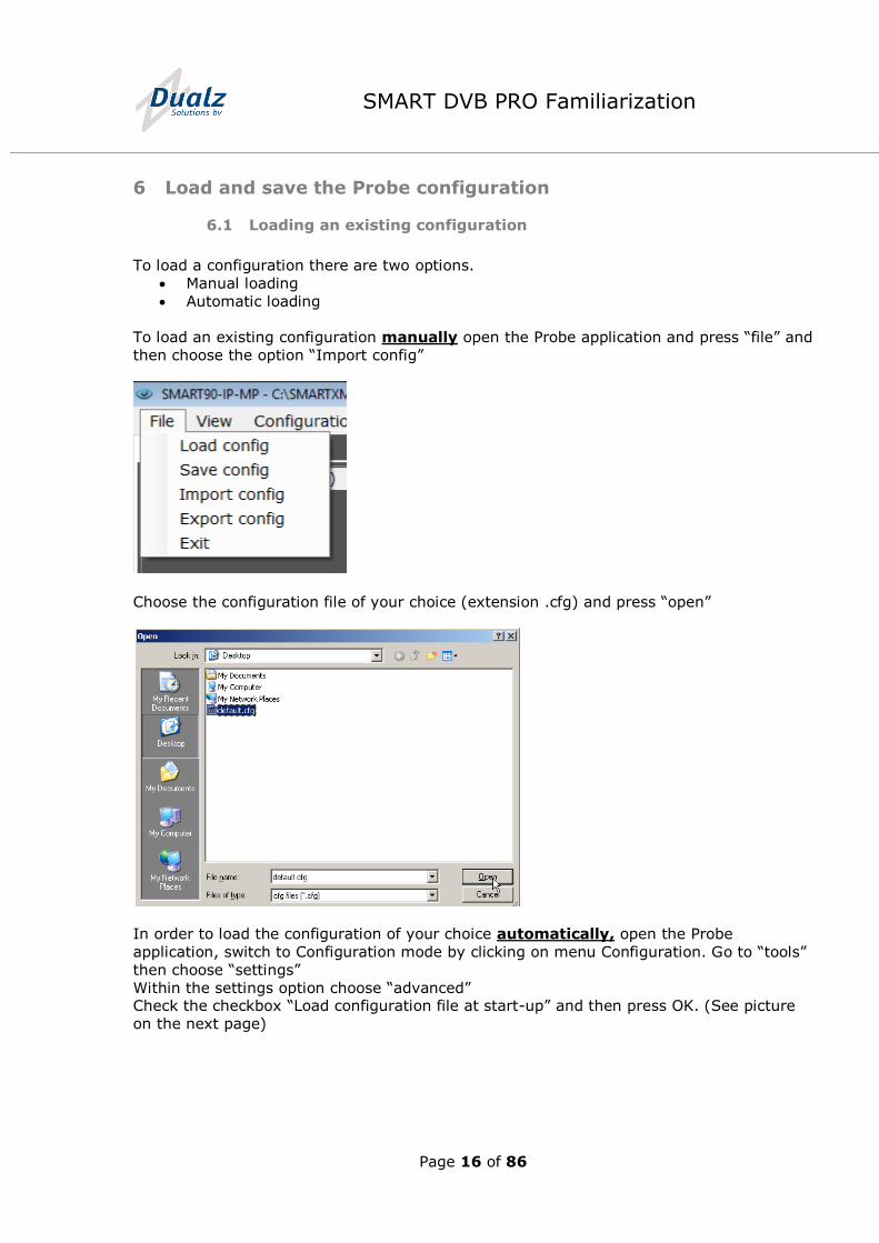
To load an existing configuration manually open the Probe application and press “file” and
then choose the option “Import config”
Choose the configuration file of your choice (extension .cfg) and press “open”
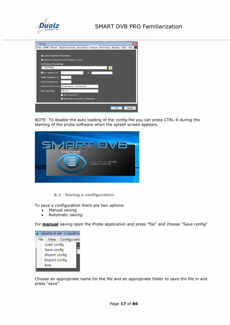
In order to load the configuration of your choice automatically, open the Probe
application, switch to Configuration mode by clicking on menu Configuration. Go to “tools”
then choose “settings”
Within the settings option choose “advanced” Check the checkbox “Load configuration file at start-up” and then press OK. (See picture
on the next page)
Page 17 of 86
SMART DVB PRO Familiarization
NOTE: To disable the auto loading of the config file you can press CTRL-A during the
starting of the probe software when the splash screen appears.
6.2 Saving a configuration
To save a configuration there are two options.
Manual saving
Automatic saving
For manual saving open the Probe application and press “file” and choose “Save config”
Choose an appropriate name for the file and an appropriate folder to save the file in and press “save”
Page 18 of 86
SMART DVB PRO Familiarization
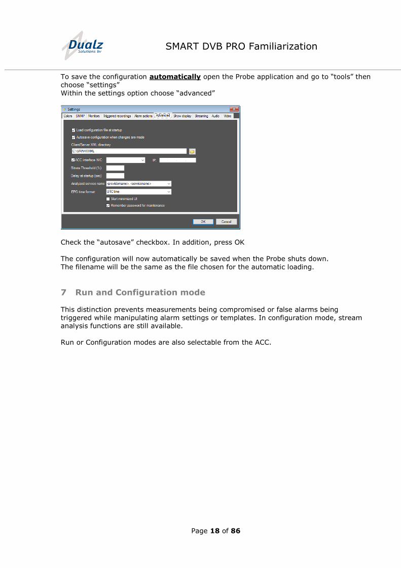
To save the configuration automatically open the Probe application and go to “tools” then
choose “settings”
Within the settings option choose “advanced”
Check the “autosave” checkbox. In addition, press OK
The configuration will now automatically be saved when the Probe shuts down.
The filename will be the same as the file chosen for the automatic loading.
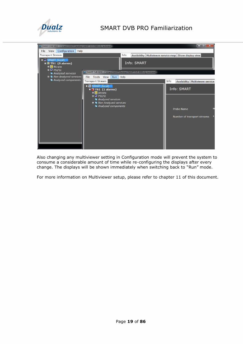
7 Run and Configuration mode
This distinction prevents measurements being compromised or false alarms being
triggered while manipulating alarm settings or templates. In configuration mode, stream analysis functions are still available.
Run or Configuration modes are also selectable from the ACC.
Page 19 of 86
SMART DVB PRO Familiarization
Also changing any multiviewer setting in Configuration mode will prevent the system to consume a considerable amount of time while re-configuring the displays after every
change. The displays will be shown immediately when switching back to “Run” mode.
For more information on Multiviewer setup, please refer to chapter 11 of this document.
Page 20 of 86
SMART DVB PRO Familiarization
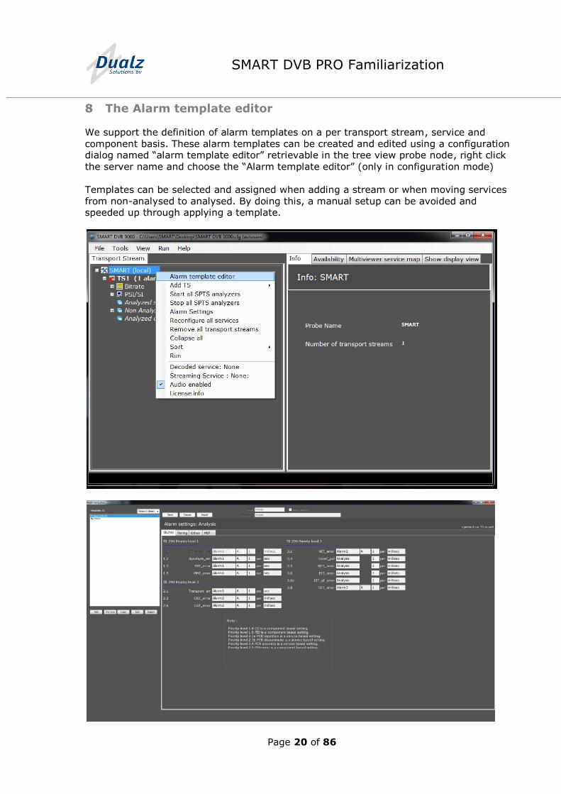
8 The Alarm template editor
We support the definition of alarm templates on a per transport stream, service and
component basis. These alarm templates can be created and edited using a configuration dialog named “alarm template editor” retrievable in the tree view probe node, right click
the server name and choose the “Alarm template editor” (only in configuration mode)
Templates can be selected and assigned when adding a stream or when moving services
from non-analysed to analysed. By doing this, a manual setup can be avoided and speeded up through applying a template.
Page 21 of 86
SMART DVB PRO Familiarization
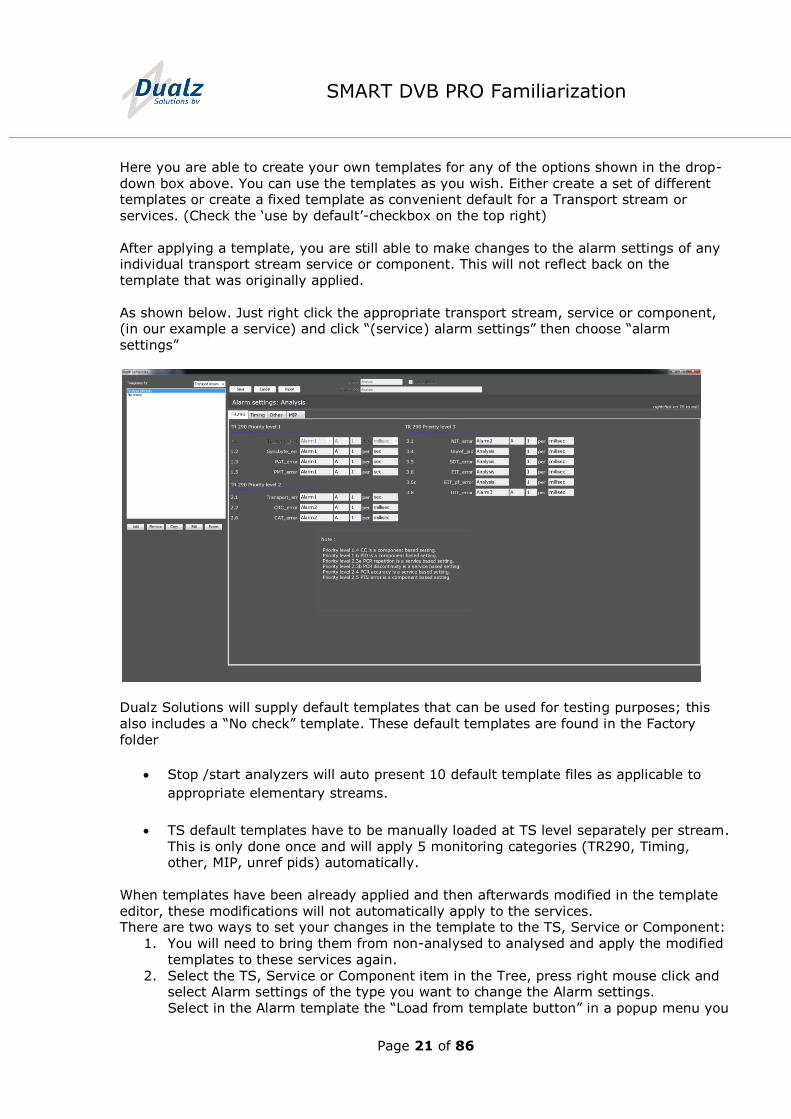
Here you are able to create your own templates for any of the options shown in the drop-
down box above. You can use the templates as you wish. Either create a set of different templates or create a fixed template as convenient default for a Transport stream or
services. (Check the ‘use by default’-checkbox on the top right)
After applying a template, you are still able to make changes to the alarm settings of any individual transport stream service or component. This will not reflect back on the
template that was originally applied.
As shown below. Just right click the appropriate transport stream, service or component, (in our example a service) and click “(service) alarm settings” then choose “alarm
settings”
Dualz Solutions will supply default templates that can be used for testing purposes; this
also includes a “No check” template. These default templates are found in the Factory
folder
Stop /start analyzers will auto present 10 default template files as applicable to
appropriate elementary streams.
TS default templates have to be manually loaded at TS level separately per stream.
This is only done once and will apply 5 monitoring categories (TR290, Timing, other, MIP, unref pids) automatically.
When templates have been already applied and then afterwards modified in the template
editor, these modifications will not automatically apply to the services. There are two ways to set your changes in the template to the TS, Service or Component:
1. You will need to bring them from non-analysed to analysed and apply the modified
templates to these services again.
2. Select the TS, Service or Component item in the Tree, press right mouse click and select Alarm settings of the type you want to change the Alarm settings.
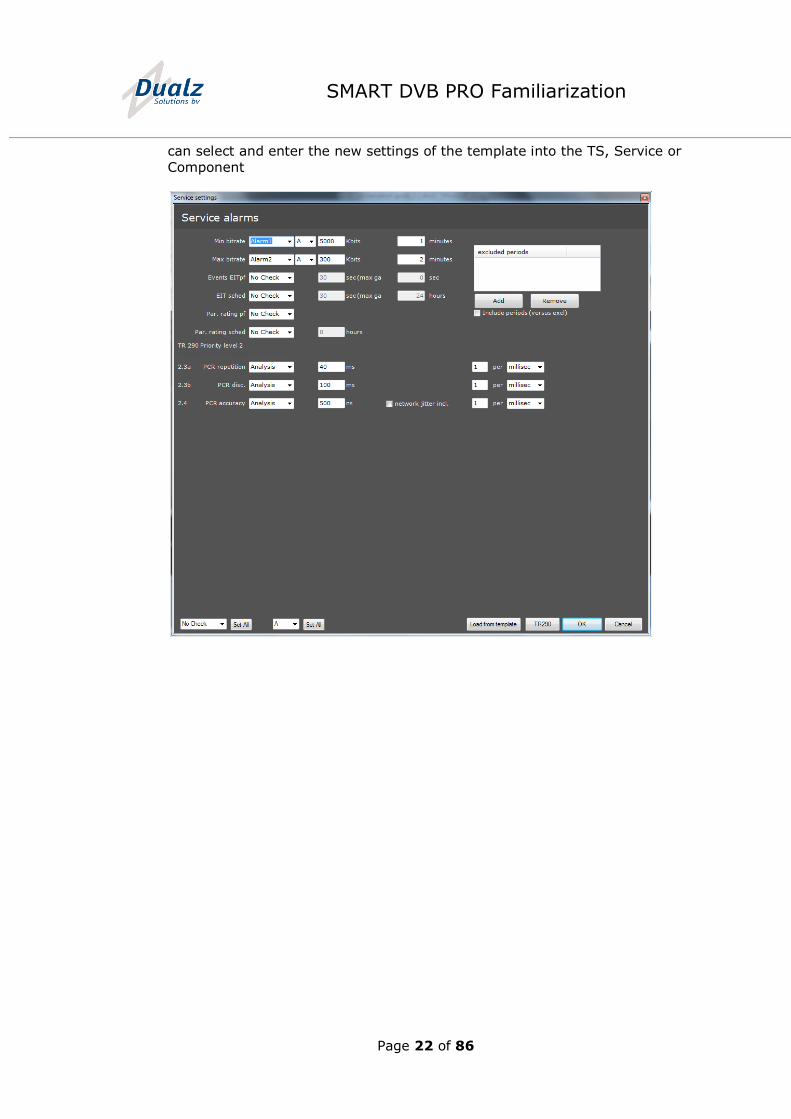
Select in the Alarm template the “Load from template button” in a popup menu you
Page 22 of 86
SMART DVB PRO Familiarization
can select and enter the new settings of the template into the TS, Service or
Component
Page 23 of 86
SMART DVB PRO Familiarization
9 Add and Remove an IP or ASI transport stream to the Probe
9.1 Adding and removing an IP transport stream
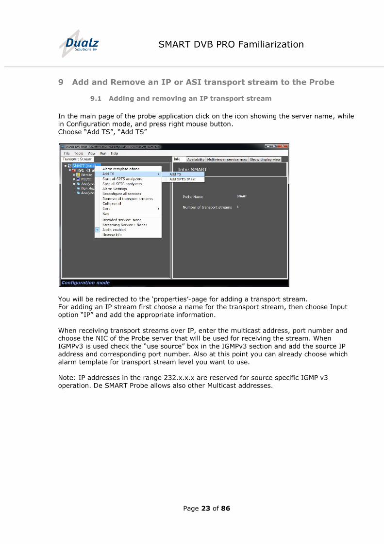
In the main page of the probe application click on the icon showing the server name, while
in Configuration mode, and press right mouse button.
Choose “Add TS”, “Add TS”
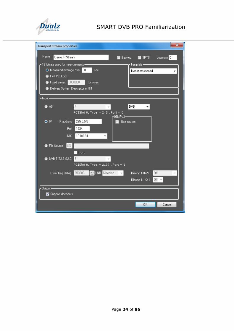
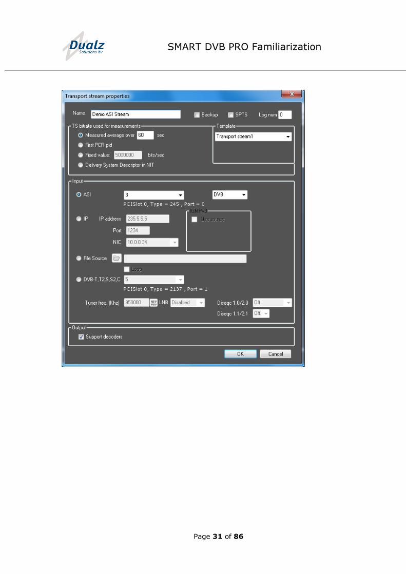
You will be redirected to the ‘properties’-page for adding a transport stream. For adding an IP stream first choose a name for the transport stream, then choose Input
option “IP” and add the appropriate information.
When receiving transport streams over IP, enter the multicast address, port number and choose the NIC of the Probe server that will be used for receiving the stream. When
IGMPv3 is used check the “use source” box in the IGMPv3 section and add the source IP
address and corresponding port number. Also at this point you can already choose which
alarm template for transport stream level you want to use.
Note: IP addresses in the range 232.x.x.x are reserved for source specific IGMP v3
operation. De SMART Probe allows also other Multicast addresses.
Page 24 of 86
SMART DVB PRO Familiarization
Page 25 of 86
SMART DVB PRO Familiarization
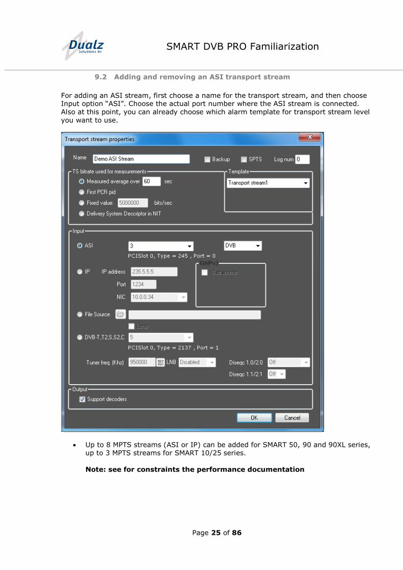
9.2 Adding and removing an ASI transport stream
For adding an ASI stream, first choose a name for the transport stream, and then choose Input option “ASI”. Choose the actual port number where the ASI stream is connected.
Also at this point, you can already choose which alarm template for transport stream level
you want to use.
Up to 8 MPTS streams (ASI or IP) can be added for SMART 50, 90 and 90XL series, up to 3 MPTS streams for SMART 10/25 series.
Note: see for constraints the performance documentation
Page 26 of 86
SMART DVB PRO Familiarization
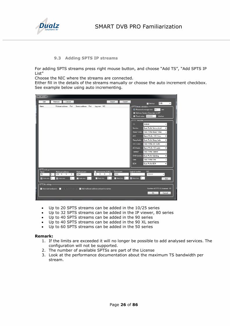
9.3 Adding SPTS IP streams
For adding SPTS streams press right mouse button, and choose “Add TS”, “Add SPTS IP
List”
Choose the NIC where the streams are connected. Either fill in the details of the streams manually or choose the auto increment checkbox.
See example below using auto incrementing.
Up to 20 SPTS streams can be added in the 10/25 series
Up to 32 SPTS streams can be added in the IP viewer, 80 series
Up to 40 SPTS streams can be added in the 90 series
Up to 40 SPTS streams can be added in the 90 XL series Up to 60 SPTS streams can be added in the 50 series
Remark:
1. If the limits are exceeded it will no longer be possible to add analysed services. The
configuration will not be supported. 2. The number of available SPTSs are part of the License
3. Look at the performance documentation about the maximum TS bandwidth per
stream.
Page 27 of 86
SMART DVB PRO Familiarization
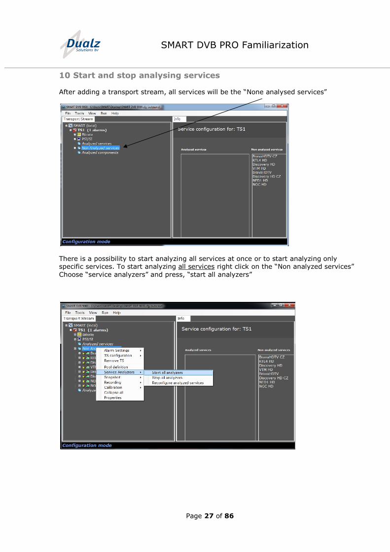
10 Start and stop analysing services
After adding a transport stream, all services will be the “None analysed services”
There is a possibility to start analyzing all services at once or to start analyzing only specific services. To start analyzing all services right click on the “Non analyzed services”
Choose “service analyzers” and press, “start all analyzers”
Page 28 of 86
SMART DVB PRO Familiarization
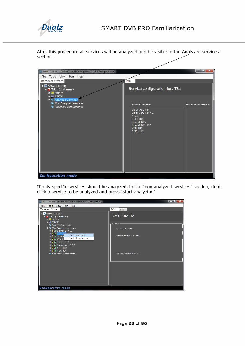
After this procedure all services will be analyzed and be visible in the Analyzed services
section.
If only specific services should be analyzed, in the “non analyzed services” section, right
click a service to be analyzed and press “start analyzing”
Page 29 of 86
SMART DVB PRO Familiarization
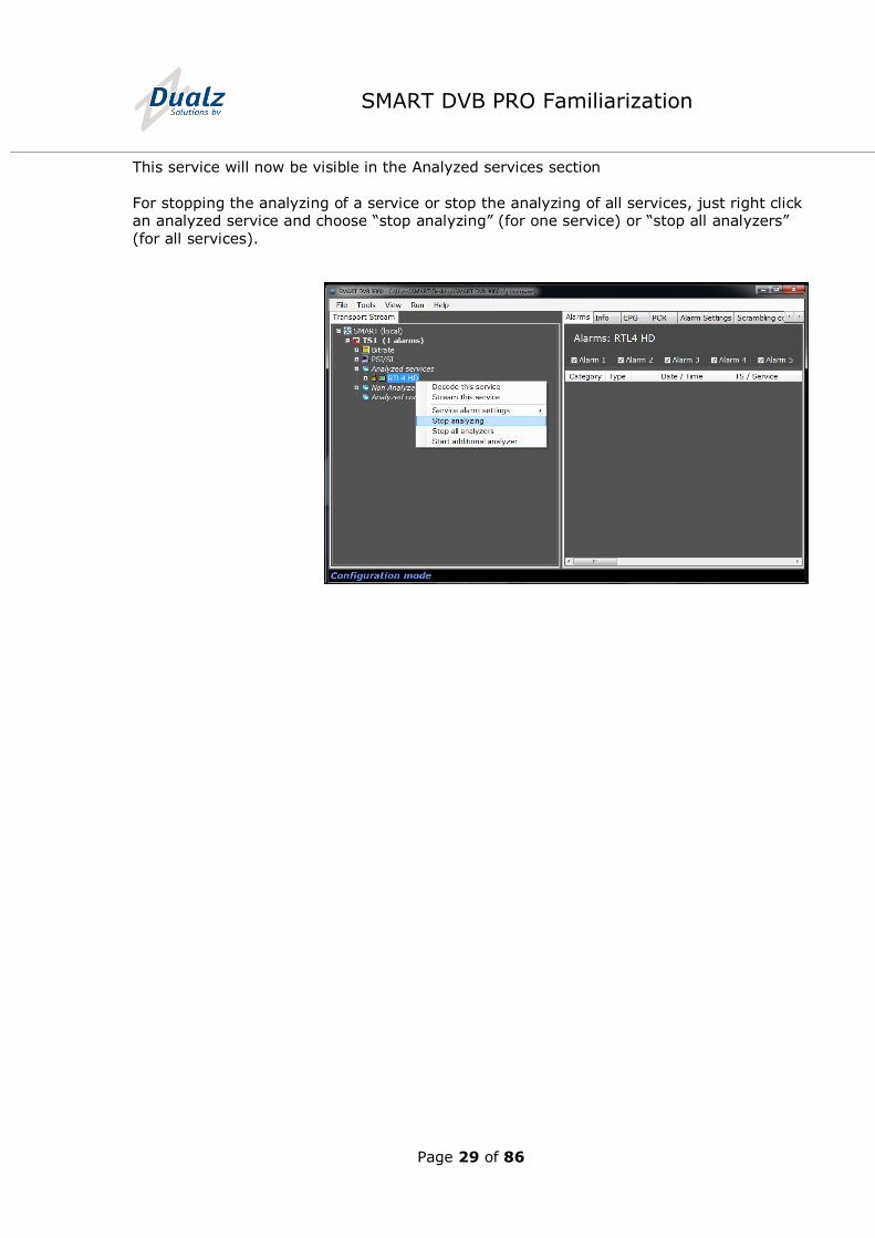
This service will now be visible in the Analyzed services section
For stopping the analyzing of a service or stop the analyzing of all services, just right click an analyzed service and choose “stop analyzing” (for one service) or “stop all analyzers”
(for all services).
Page 30 of 86
SMART DVB PRO Familiarization
11 Explanation of the Probe tree
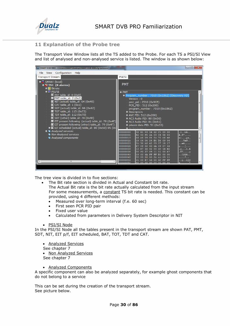
The Transport View Window lists all the TS added to the Probe. For each TS a PSI/SI View
and list of analysed and non-analysed service is listed. The window is as shown below:
The tree view is divided in to five sections: The Bit rate section is divided in Actual and Constant bit rate.
The Actual Bit rate is the bit rate actually calculated from the input stream
For some measurements, a constant TS bit rate is needed. This constant can be
provided, using 4 different methods:
Measured over long-term interval (f.e. 60 sec) First seen PCR PID pair
Fixed user value
Calculated from parameters in Delivery System Descriptor in NIT
PSI/SI Node
In the PSI/SI Node all the tables present in the transport stream are shown PAT, PMT,
SDT, NIT, EIT p/f, EIT scheduled, BAT, TOT, TDT and CAT.
Analyzed Services
See chapter 7
Non Analyzed Services
See chapter 7
Analyzed Components
A specific component can also be analyzed separately, for example ghost components that
do not belong to a service
This can be set during the creation of the transport stream.
See picture below.
Page 31 of 86
SMART DVB PRO Familiarization
Page 32 of 86
SMART DVB PRO Familiarization
12 Basic monitoring views
12.1 TR290 view
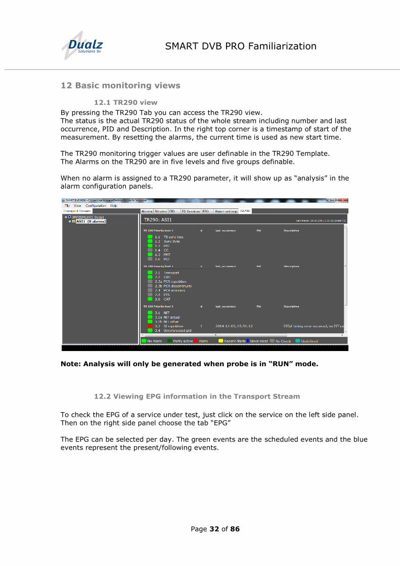
By pressing the TR290 Tab you can access the TR290 view.
The status is the actual TR290 status of the whole stream including number and last
occurrence, PID and Description. In the right top corner is a timestamp of start of the
measurement. By resetting the alarms, the current time is used as new start time.
The TR290 monitoring trigger values are user definable in the TR290 Template.
The Alarms on the TR290 are in five levels and five groups definable.
When no alarm is assigned to a TR290 parameter, it will show up as “analysis” in the alarm configuration panels.
Note: Analysis will only be generated when probe is in “RUN” mode.
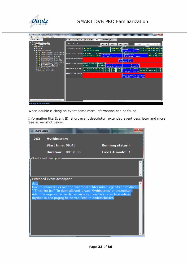
12.2 Viewing EPG information in the Transport Stream
To check the EPG of a service under test, just click on the service on the left side panel.
Then on the right side panel choose the tab “EPG”
The EPG can be selected per day. The green events are the scheduled events and the blue
events represent the present/following events.
Page 33 of 86
SMART DVB PRO Familiarization
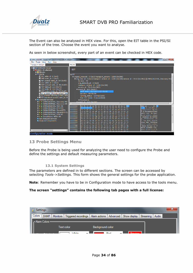
When double clicking an event some more information can be found.
Information like Event ID, short event descriptor, extended event descriptor and more.
See screenshot below.
Page 34 of 86
SMART DVB PRO Familiarization
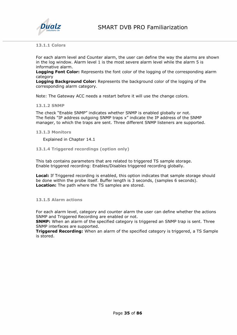
The Event can also be analysed in HEX view. For this, open the EIT table in the PSI/SI
section of the tree. Choose the event you want to analyse.
As seen in below screenshot, every part of an event can be checked in HEX code.
13 Probe Settings Menu
Before the Probe is being used for analyzing the user need to configure the Probe and
define the settings and default measuring parameters.
13.1 System Settings
The parameters are defined in to different sections. The screen can be accessed by
selecting Tools->Settings. This form shows the general settings for the probe application.
Note: Remember you have to be in Configuration mode to have access to the tools menu.
The screen “settings” contains the following tab pages with a full license:
Page 35 of 86
SMART DVB PRO Familiarization
13.1.1 Colors
For each alarm level and Counter alarm, the user can define the way the alarms are shown in the log window. Alarm level 1 is the most severe alarm level while the alarm 5 is
informative alarm.
Logging Font Color: Represents the font color of the logging of the corresponding alarm
category Logging Background Color: Represents the background color of the logging of the
corresponding alarm category.
Note: The Gateway ACC needs a restart before it will use the change colors.
13.1.2 SNMP
The check “Enable SNMP” indicates whether SNMP is enabled globally or not.
The fields "IP address outgoing SNMP traps x” indicate the IP address of the SNMP
manager, to which the traps are sent. Three different SNMP listeners are supported.
13.1.3 Monitors
Explained in Chapter 14.1
13.1.4 Triggered recordings (option only)
This tab contains parameters that are related to triggered TS sample storage. Enable triggered recording: Enables/Disables triggered recording globally.
Local: If Triggered recording is enabled, this option indicates that sample storage should
be done within the probe itself. Buffer length is 3 seconds, (samples 6 seconds). Location: The path where the TS samples are stored.
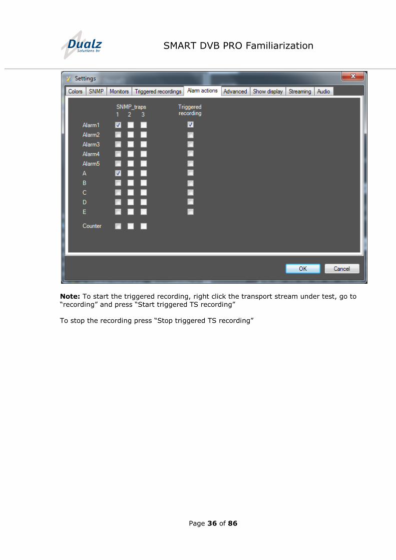
13.1.5 Alarm actions
For each alarm level, category and counter alarm the user can define whether the actions
SNMP and Triggered Recording are enabled or not.
SNMP: When an alarm of the specified category is triggered an SNMP trap is sent. Three
SNMP interfaces are supported.
Triggered Recording: When an alarm of the specified category is triggered, a TS Sample is stored.
Page 36 of 86
SMART DVB PRO Familiarization
Note: To start the triggered recording, right click the transport stream under test, go to
“recording” and press “Start triggered TS recording”
To stop the recording press “Stop triggered TS recording”
Page 37 of 86
SMART DVB PRO Familiarization
14 Multi-viewer configurator
14.1 Generic Multi-viewer settings
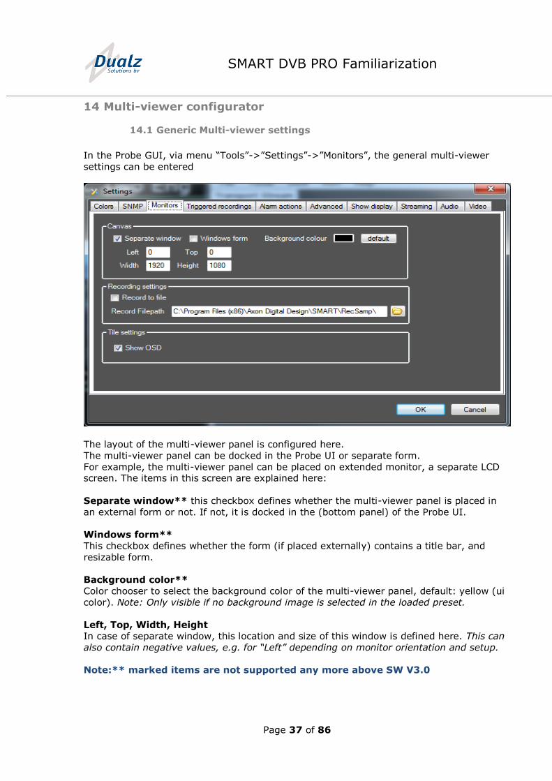
In the Probe GUI, via menu “Tools”->”Settings”->”Monitors”, the general multi-viewer
settings can be entered
The layout of the multi-viewer panel is configured here.
The multi-viewer panel can be docked in the Probe UI or separate form.
For example, the multi-viewer panel can be placed on extended monitor, a separate LCD screen. The items in this screen are explained here:
Separate window** this checkbox defines whether the multi-viewer panel is placed in
an external form or not. If not, it is docked in the (bottom panel) of the Probe UI.
Windows form**
This checkbox defines whether the form (if placed externally) contains a title bar, and
resizable form.
Background color**
Color chooser to select the background color of the multi-viewer panel, default: yellow (ui
color). Note: Only visible if no background image is selected in the loaded preset.
Left, Top, Width, Height
In case of separate window, this location and size of this window is defined here. This can
also contain negative values, e.g. for “Left” depending on monitor orientation and setup.
Note:** marked items are not supported any more above SW V3.0
Page 38 of 86
SMART DVB PRO Familiarization
Directory
This textbox defines the directory where the presets (xml files) are stored.
Note: Read-only.
Record to file (option)
This checkbox defines whether the services can be stored to disk or not.
Note: The services are stored in compressed format.
Record File path
This checkbox defines the path where the service samples are stored.
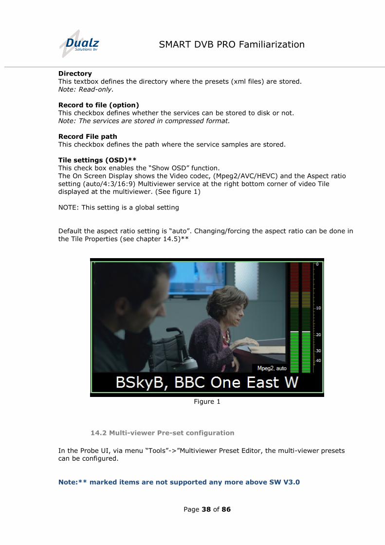
Tile settings (OSD)**
This check box enables the “Show OSD” function.
The On Screen Display shows the Video codec, (Mpeg2/AVC/HEVC) and the Aspect ratio
setting (auto/4:3/16:9) Multiviewer service at the right bottom corner of video Tile displayed at the multiviewer. (See figure 1)
NOTE: This setting is a global setting
Default the aspect ratio setting is “auto”. Changing/forcing the aspect ratio can be done in
the Tile Properties (see chapter 14.5)**
Figure 1
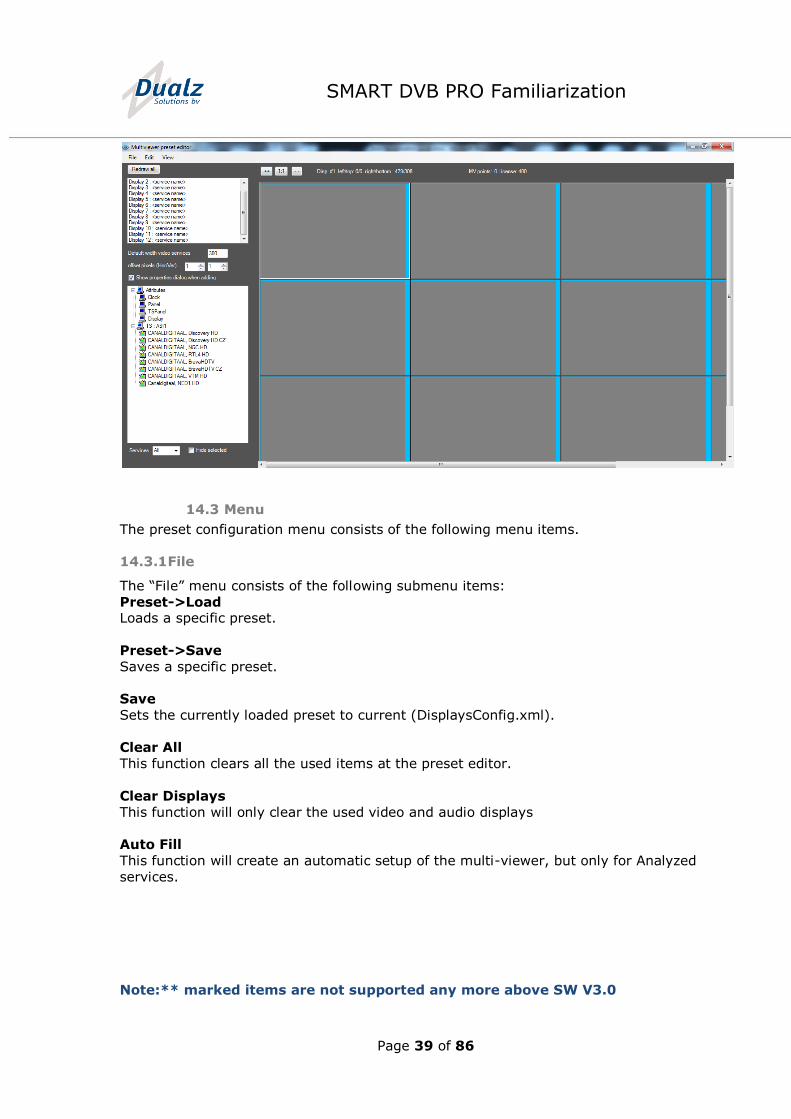
14.2 Multi-viewer Pre-set configuration
In the Probe UI, via menu “Tools”->”Multiviewer Preset Editor, the multi-viewer presets can be configured.
Note:** marked items are not supported any more above SW V3.0
Page 39 of 86
SMART DVB PRO Familiarization
14.3 Menu
The preset configuration menu consists of the following menu items.
14.3.1 File
The “File” menu consists of the following submenu items:
Preset->Load Loads a specific preset.
Preset->Save
Saves a specific preset.
Save
Sets the currently loaded preset to current (DisplaysConfig.xml).
Clear All
This function clears all the used items at the preset editor.
Clear Displays
This function will only clear the used video and audio displays
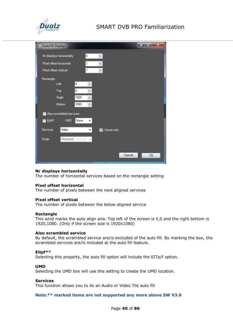
Auto Fill
This function will create an automatic setup of the multi-viewer, but only for Analyzed
services.
Note:** marked items are not supported any more above SW V3.0
Page 40 of 86
SMART DVB PRO Familiarization
Nr displays horizontally
The number of horizontal services based on the rectangle setting
Pixel offset horizontal The number of pixels between the next aligned services
Pixel offset vertical
The number of pixels between the below aligned service
Rectangle
This wind marks the auto align aria. Top left of the screen is 0,0 and the right bottom is
1920,1080. (Only if the screen size is 1920x1080)
Also scrambled service
By default, the scrambled service are/is excluded of the auto fill. By marking the box, the
scrambled services are/is included at the auto fill feature.
Eitpf**
Selecting this property, the auto fill option will include the EITp/f option.
UMD Selecting the UMD box will use this setting to create the UMD location.
Services
This function allows you to do an Audio or Video Tile auto fill
Note:** marked items are not supported any more above SW V3.0
Page 41 of 86
SMART DVB PRO Familiarization
I-frame only**
This selection will switch off the full frame decoding and will display only the I-frames of the video services.
Order
By default, the function will draw the horizontal order. By selecting vertical the drawing order in from the left top to the left bottom. (This function is not active)
Note: Make sure that the 1920x1080 Full HD multi-viewer screen has been set to either
“screen fit” or “scan” and not fixed to 16:9
14.3.2 Edit
The “Edit” menu consists of the following submenu items:
Undo
Rollback to previous edit action.
Add
Adds a multi-viewer entity (display, clock, panel, URL display).
Remove selected item Removes the currently selected multi-viewer entity.
Preset properties
Opens preset properties form.
14.3.3 View
The “View” menu consists of the following submenu items:
Refresh
Redraw of the preview panel.
Zoom in (++)
Zoom function, to see more detail.
Zoom out (--) Zoom function, to create higher-level view
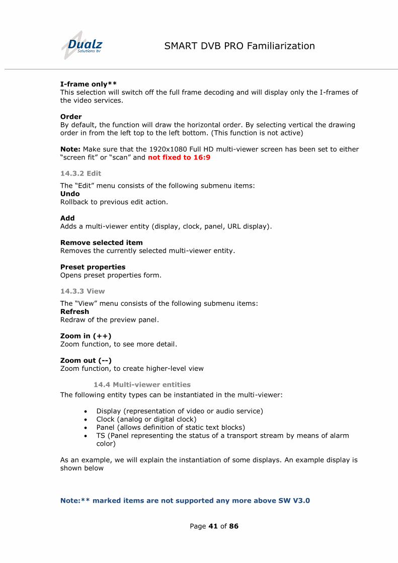
14.4 Multi-viewer entities
The following entity types can be instantiated in the multi-viewer:
Display (representation of video or audio service)
Clock (analog or digital clock)
Panel (allows definition of static text blocks)
TS (Panel representing the status of a transport stream by means of alarm color)
As an example, we will explain the instantiation of some displays. An example display is
shown below
Note:** marked items are not supported any more above SW V3.0
Page 42 of 86
SMART DVB PRO Familiarization
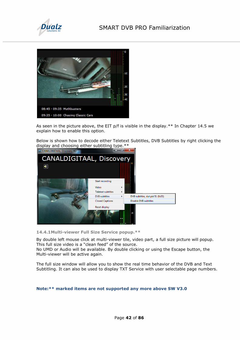
As seen in the picture above, the EIT p/f is visible in the display.** In Chapter 14.5 we
explain how to enable this option.
Below is shown how to decode either Teletext Subtitles, DVB Subtitles by right clicking the
display and choosing either subtitling type.**
14.4.1 Multi-viewer Full Size Service popup.**
By double left mouse click at multi-viewer tile, video part, a full size picture will popup.
This full size video is a “clean feed” of the source.
No UMD or Audio will be available. By double clicking or using the Escape button, the Multi-viewer will be active again.
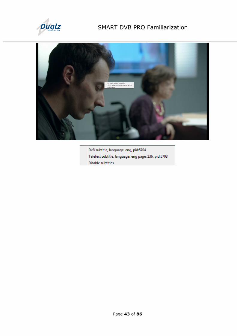
The full size window will allow you to show the real time behavior of the DVB and Text
Subtitling. It can also be used to display TXT Service with user selectable page numbers.
Note:** marked items are not supported any more above SW V3.0
Page 43 of 86
SMART DVB PRO Familiarization
Page 44 of 86
SMART DVB PRO Familiarization
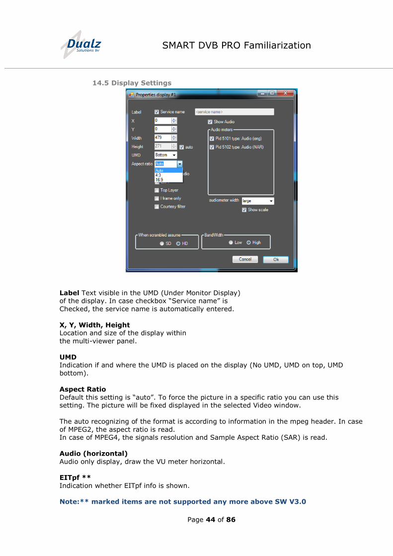
14.5 Display Settings
Label Text visible in the UMD (Under Monitor Display) of the display. In case checkbox “Service name” is
Checked, the service name is automatically entered.
X, Y, Width, Height Location and size of the display within
the multi-viewer panel.
UMD Indication if and where the UMD is placed on the display (No UMD, UMD on top, UMD
bottom).
Aspect Ratio
Default this setting is “auto”. To force the picture in a specific ratio you can use this setting. The picture will be fixed displayed in the selected Video window.
The auto recognizing of the format is according to information in the mpeg header. In case
of MPEG2, the aspect ratio is read. In case of MPEG4, the signals resolution and Sample Aspect Ratio (SAR) is read.
Audio (horizontal)
Audio only display, draw the VU meter horizontal.
EITpf **
Indication whether EITpf info is shown.
Note:** marked items are not supported any more above SW V3.0
Page 45 of 86
SMART DVB PRO Familiarization
Top Layer
Indication whether the display is drawn on top or not.
I-Frame Only**
Only shows I-Frames, decreases CPU usages.
Courtesy filter **
Use to block the display when inappropriate content is displayed.
Show Audio ** By selecting this checkbox, the audio meters (bars) will be viewed according the number
of selected audio Pids. The SMART can have up to five audio bars displayed)
Audiometer** To select the audio PIDs according to the video tile.
Audiometer width**
SMART can have different sizes of audio bars
Show scale
This option allows switching off the scale of the audio bar.
When scrambled assume (SD/HD) When displaying a Scrambled Service at the Multi-viewer select the actual and real
resolution. This switch is used to protect the system and allows you to use the realistic
point counts. By default, an unrecognized service is defined as HD, the highest point
count.
Bandwidth (Low/High)
This option allows you to adjust the actual used bandwidth and is just to protect the
system against memory and CPU overload.
By default, the High selection is set. Low can be set when using Mpeg2/H264/AVC/Mpeg4 part 10/H265/HEVC is < 8 Mbps
video bandwidth.
Note:** marked items are not supported any more above SW V3.0
Page 46 of 86
SMART DVB PRO Familiarization
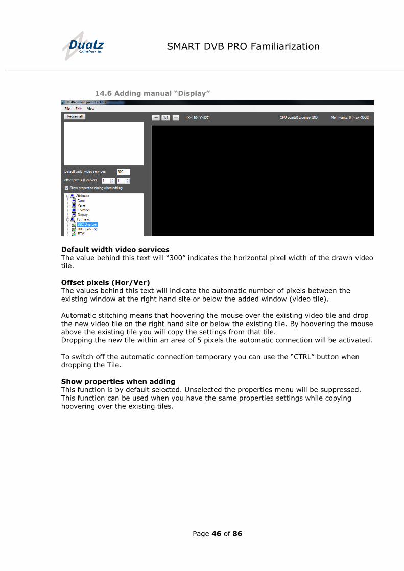
14.6 Adding manual “Display”
Default width video services
The value behind this text will “300” indicates the horizontal pixel width of the drawn video tile.
Offset pixels (Hor/Ver)
The values behind this text will indicate the automatic number of pixels between the existing window at the right hand site or below the added window (video tile).
Automatic stitching means that hoovering the mouse over the existing video tile and drop
the new video tile on the right hand site or below the existing tile. By hoovering the mouse above the existing tile you will copy the settings from that tile.
Dropping the new tile within an area of 5 pixels the automatic connection will be activated.
To switch off the automatic connection temporary you can use the “CTRL” button when
dropping the Tile.
Show properties when adding
This function is by default selected. Unselected the properties menu will be suppressed.
This function can be used when you have the same properties settings while copying hoovering over the existing tiles.
Page 47 of 86
SMART DVB PRO Familiarization
14.7 Adding some multiviewer entities (attributes)
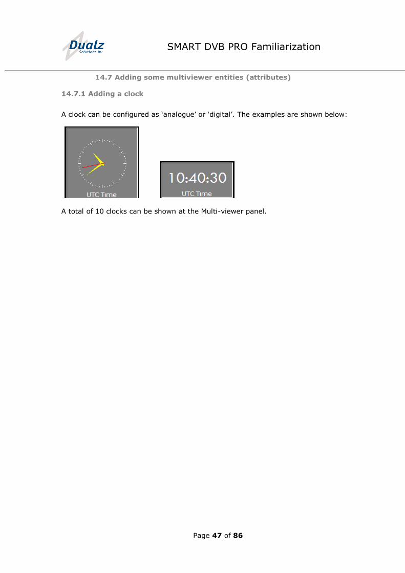
14.7.1 Adding a clock
A clock can be configured as ‘analogue’ or ‘digital’. The examples are shown below:
A total of 10 clocks can be shown at the Multi-viewer panel.
Page 48 of 86
SMART DVB PRO Familiarization
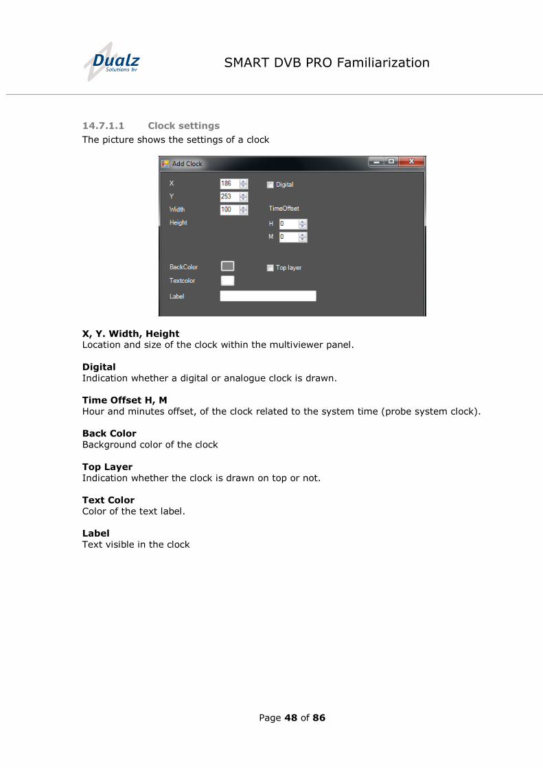
14.7.1.1 Clock settings
The picture shows the settings of a clock
X, Y. Width, Height Location and size of the clock within the multiviewer panel.
Digital
Indication whether a digital or analogue clock is drawn.
Time Offset H, M
Hour and minutes offset, of the clock related to the system time (probe system clock).
Back Color
Background color of the clock
Top Layer
Indication whether the clock is drawn on top or not.
Text Color
Color of the text label.
Label
Text visible in the clock
Page 49 of 86
SMART DVB PRO Familiarization
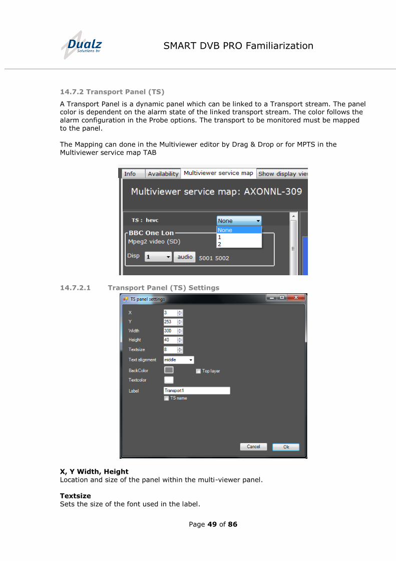
14.7.2 Transport Panel (TS)
A Transport Panel is a dynamic panel which can be linked to a Transport stream. The panel color is dependent on the alarm state of the linked transport stream. The color follows the
alarm configuration in the Probe options. The transport to be monitored must be mapped
to the panel.
The Mapping can done in the Multiviewer editor by Drag & Drop or for MPTS in the
Multiviewer service map TAB
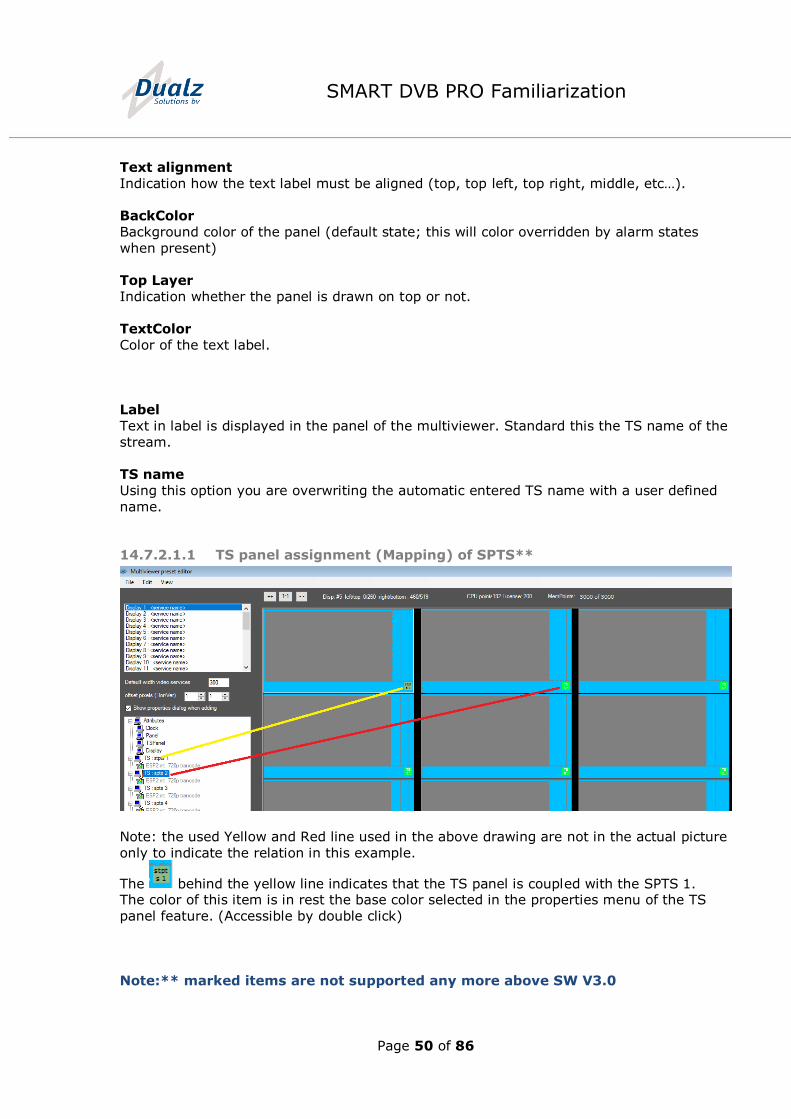
14.7.2.1 Transport Panel (TS) Settings
X, Y Width, Height
Location and size of the panel within the multi-viewer panel.
Textsize
Sets the size of the font used in the label.
Page 50 of 86
SMART DVB PRO Familiarization
Text alignment
Indication how the text label must be aligned (top, top left, top right, middle, etc…).
BackColor
Background color of the panel (default state; this will color overridden by alarm states
when present)
Top Layer
Indication whether the panel is drawn on top or not.
TextColor
Color of the text label.
Label
Text in label is displayed in the panel of the multiviewer. Standard this the TS name of the
stream.
TS name
Using this option you are overwriting the automatic entered TS name with a user defined
name.
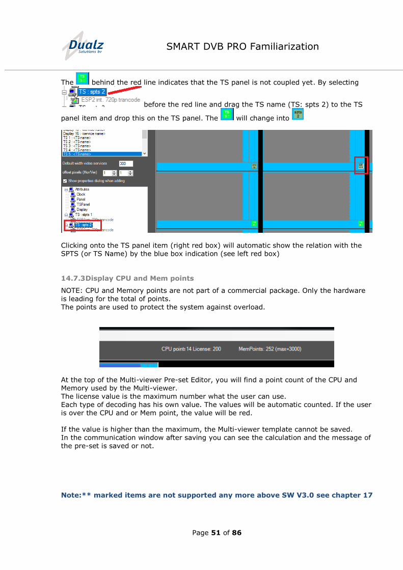
14.7.2.1.1 TS panel assignment (Mapping) of SPTS**
Note: the used Yellow and Red line used in the above drawing are not in the actual picture
only to indicate the relation in this example.
The behind the yellow line indicates that the TS panel is coupled with the SPTS 1. The color of this item is in rest the base color selected in the properties menu of the TS
panel feature. (Accessible by double click)
Note:** marked items are not supported any more above SW V3.0
Page 51 of 86
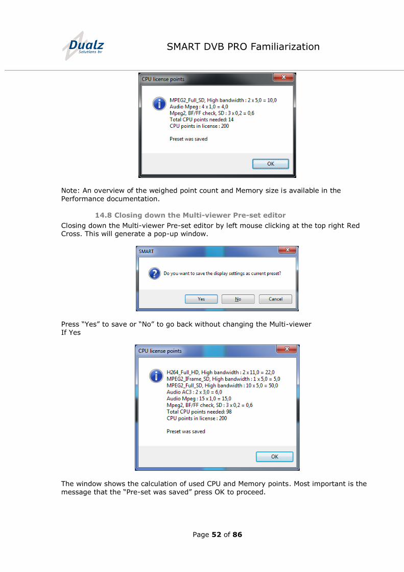
SMART DVB PRO Familiarization
The behind the red line indicates that the TS panel is not coupled yet. By selecting
before the red line and drag the TS name (TS: spts 2) to the TS
panel item and drop this on the TS panel. The will change into
Clicking onto the TS panel item (right red box) will automatic show the relation with the
SPTS (or TS Name) by the blue box indication (see left red box)
14.7.3 Display CPU and Mem points
NOTE: CPU and Memory points are not part of a commercial package. Only the hardware
is leading for the total of points.
The points are used to protect the system against overload.
At the top of the Multi-viewer Pre-set Editor, you will find a point count of the CPU and
Memory used by the Multi-viewer.
The license value is the maximum number what the user can use.
Each type of decoding has his own value. The values will be automatic counted. If the user
is over the CPU and or Mem point, the value will be red.
If the value is higher than the maximum, the Multi-viewer template cannot be saved.
In the communication window after saving you can see the calculation and the message of
the pre-set is saved or not.
Note:** marked items are not supported any more above SW V3.0 see chapter 17
Page 52 of 86
SMART DVB PRO Familiarization
Note: An overview of the weighed point count and Memory size is available in the
Performance documentation.
14.8 Closing down the Multi-viewer Pre-set editor
Closing down the Multi-viewer Pre-set editor by left mouse clicking at the top right Red Cross. This will generate a pop-up window.
Press “Yes” to save or “No” to go back without changing the Multi-viewer
If Yes
The window shows the calculation of used CPU and Memory points. Most important is the
message that the “Pre-set was saved” press OK to proceed.
Page 53 of 86
SMART DVB PRO Familiarization
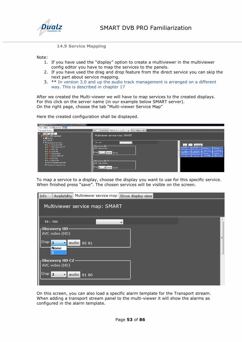
14.9 Service Mapping
Note: 1. If you have used the “display” option to create a multiviewer in the multiviewer
config editor you have to map the services to the panels.
2. If you have used the drag and drop feature from the direct service you can skip the
next part about service mapping. 3. ** In version 3.0 and up the audio track management is arranged on a different
way. This is described in chapter 17
After we created the Multi-viewer we will have to map services to the created displays. For this click on the server name (in our example below SMART server).
On the right page, choose the tab “Multi-viewer Service Map”
Here the created configuration shall be displayed.
To map a service to a display, choose the display you want to use for this specific service.
When finished press “save”. The chosen services will be visible on the screen.
On this screen, you can also load a specific alarm template for the Transport stream.
When adding a transport stream panel to the multi-viewer it will show the alarms as configured in the alarm template.
Page 54 of 86
SMART DVB PRO Familiarization
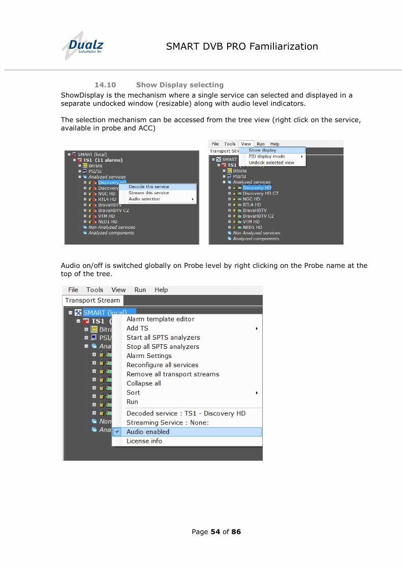
14.10 Show Display selecting
ShowDisplay is the mechanism where a single service can selected and displayed in a
separate undocked window (resizable) along with audio level indicators.
The selection mechanism can be accessed from the tree view (right click on the service,
available in probe and ACC)
Audio on/off is switched globally on Probe level by right clicking on the Probe name at the
top of the tree.
Page 55 of 86
SMART DVB PRO Familiarization
Information concerning which service/audio is selected can be retrieved from the Show
Display when the probe node selected from the tree view or when right clicking on this node.
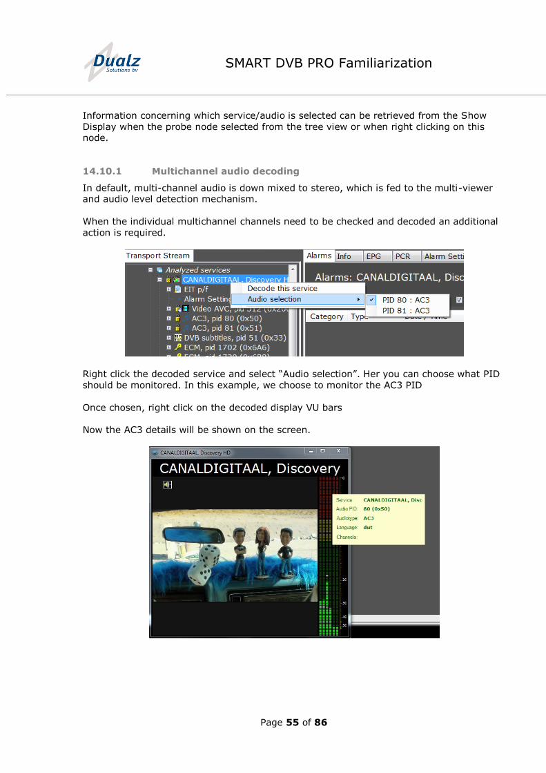
14.10.1 Multichannel audio decoding
In default, multi-channel audio is down mixed to stereo, which is fed to the multi-viewer and audio level detection mechanism.
When the individual multichannel channels need to be checked and decoded an additional
action is required.
Right click the decoded service and select “Audio selection”. Her you can choose what PID
should be monitored. In this example, we choose to monitor the AC3 PID
Once chosen, right click on the decoded display VU bars
Now the AC3 details will be shown on the screen.
Page 56 of 86
SMART DVB PRO Familiarization
15 ACC Setup for Probe connection
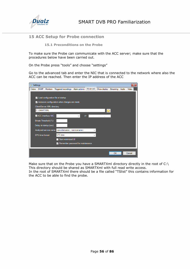
15.1 Preconditions on the Probe
To make sure the Probe can communicate with the ACC server; make sure that the
procedures below have been carried out.
On the Probe press “tools” and choose “settings”
Go to the advanced tab and enter the NIC that is connected to the network where also the
ACC can be reached. Then enter the IP address of the ACC
Make sure that on the Probe you have a SMARTXml directory directly in the root of C:\
This directory should be shared as SMARTXml with full read write access. In the root of SMARTXml there should be a file called “TSlist” this contains information for
the ACC to be able to find the probe.
Page 57 of 86
SMART DVB PRO Familiarization
15.2 Preconditions on the ACC
15.2.1 Set communication interface and port
In “Tools” > “Settings” > “Server” configure the IP address and Port number that the ACC
server shall use to communicate with probes. The default port number is 1024.
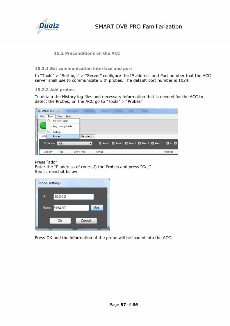
15.2.2 Add probes
To obtain the History log files and necessary information that is needed for the ACC to
detect the Probes, on the ACC go to “Tools” > “Probes”
Press “add” Enter the IP address of (one of) the Probes and press “Get”
See screenshot below
Press OK and the information of the probe will be loaded into the ACC.
Page 58 of 86
SMART DVB PRO Familiarization
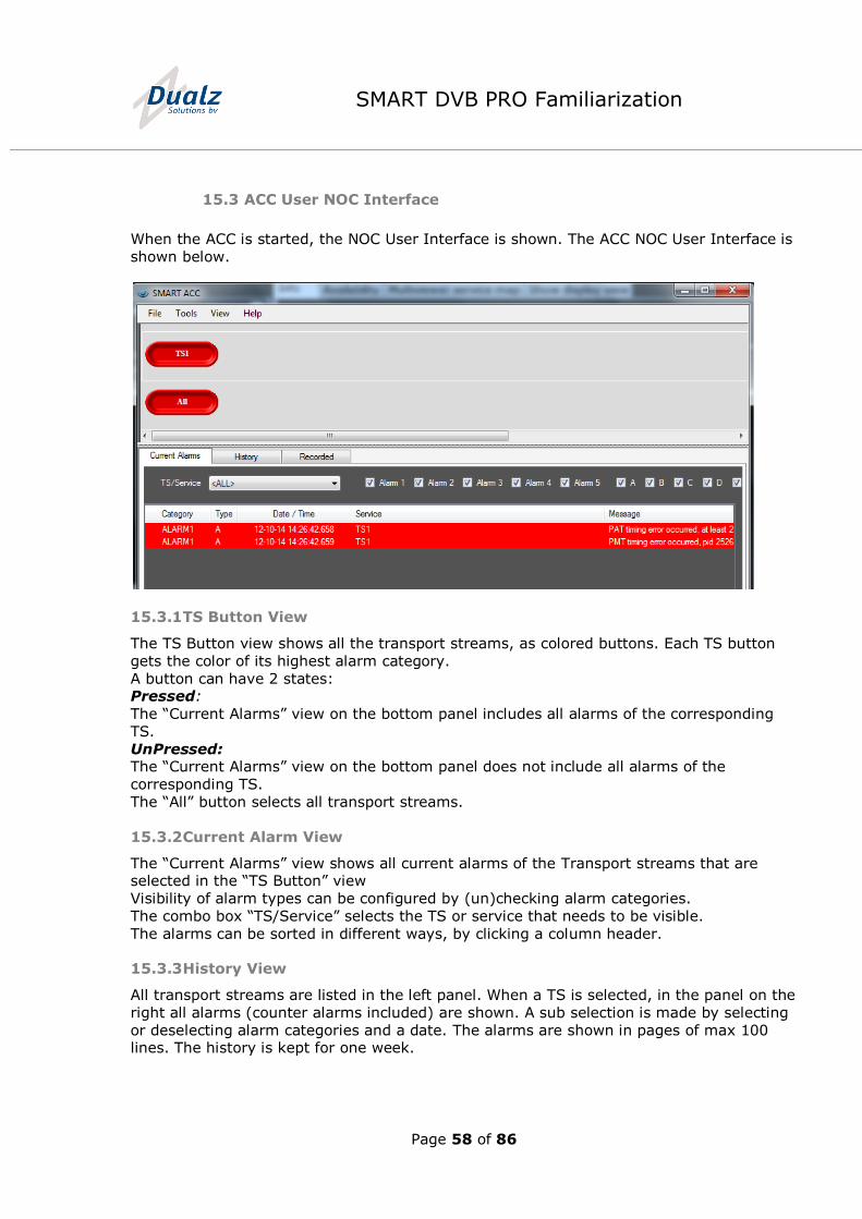
15.3 ACC User NOC Interface
When the ACC is started, the NOC User Interface is shown. The ACC NOC User Interface is
shown below.
15.3.1 TS Button View
The TS Button view shows all the transport streams, as colored buttons. Each TS button
gets the color of its highest alarm category.
A button can have 2 states: Pressed:
The “Current Alarms” view on the bottom panel includes all alarms of the corresponding
TS.
UnPressed: The “Current Alarms” view on the bottom panel does not include all alarms of the
corresponding TS.
The “All” button selects all transport streams.
15.3.2 Current Alarm View
The “Current Alarms” view shows all current alarms of the Transport streams that are selected in the “TS Button” view
Visibility of alarm types can be configured by (un)checking alarm categories.
The combo box “TS/Service” selects the TS or service that needs to be visible.
The alarms can be sorted in different ways, by clicking a column header.
15.3.3 History View
All transport streams are listed in the left panel. When a TS is selected, in the panel on the
right all alarms (counter alarms included) are shown. A sub selection is made by selecting
or deselecting alarm categories and a date. The alarms are shown in pages of max 100 lines. The history is kept for one week.
Page 59 of 86
SMART DVB PRO Familiarization
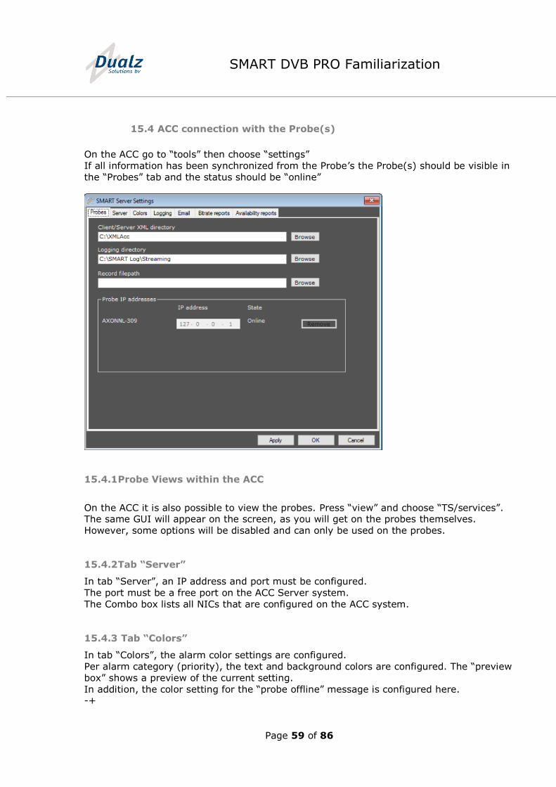
15.4 ACC connection with the Probe(s)
On the ACC go to “tools” then choose “settings”
If all information has been synchronized from the Probe’s the Probe(s) should be visible in
the “Probes” tab and the status should be “online”
15.4.1 Probe Views within the ACC
On the ACC it is also possible to view the probes. Press “view” and choose “TS/services”. The same GUI will appear on the screen, as you will get on the probes themselves.
However, some options will be disabled and can only be used on the probes.
15.4.2 Tab “Server”
In tab “Server”, an IP address and port must be configured.
The port must be a free port on the ACC Server system.
The Combo box lists all NICs that are configured on the ACC system.
15.4.3 Tab “Colors”
In tab “Colors”, the alarm color settings are configured.
Per alarm category (priority), the text and background colors are configured. The “preview
box” shows a preview of the current setting.
In addition, the color setting for the “probe offline” message is configured here. -+

Page 60 of 86
SMART DVB PRO Familiarization
Note: After changing colors, the Gateway ACC program should be restarted before it
selects the new set colors.
Page 61 of 86
SMART DVB PRO Familiarization
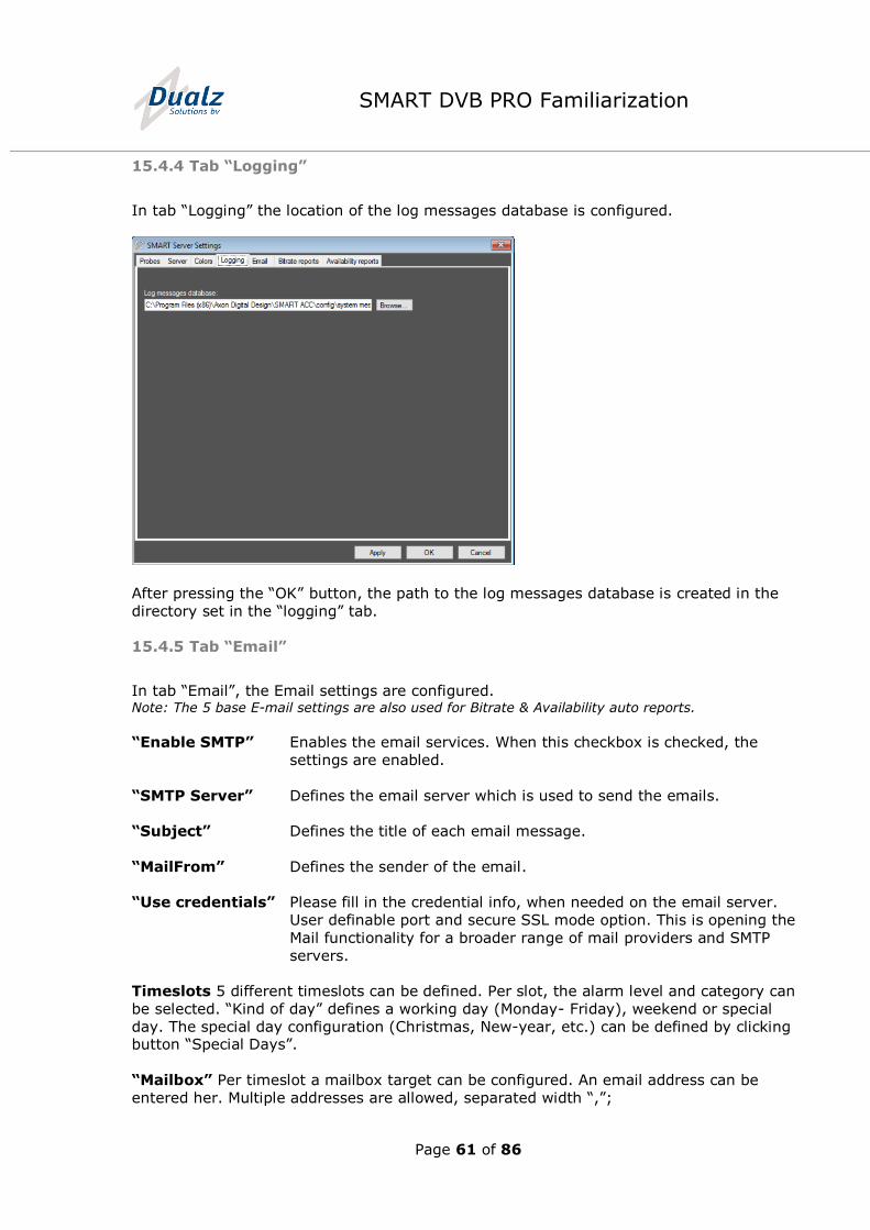
15.4.4 Tab “Logging”
In tab “Logging” the location of the log messages database is configured.
After pressing the “OK” button, the path to the log messages database is created in the
directory set in the “logging” tab.
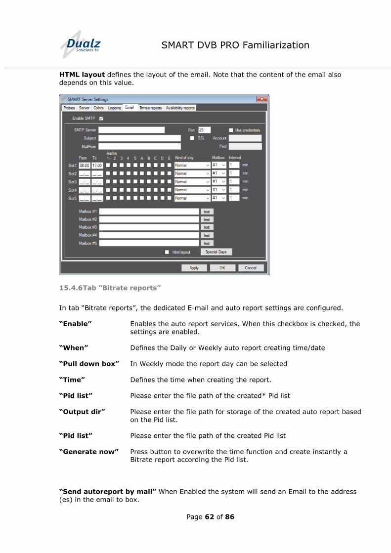
15.4.5 Tab “Email”
In tab “Email”, the Email settings are configured. Note: The 5 base E-mail settings are also used for Bitrate & Availability auto reports.
“Enable SMTP” Enables the email services. When this checkbox is checked, the
settings are enabled.
“SMTP Server” Defines the email server which is used to send the emails.
“Subject” Defines the title of each email message.
“MailFrom” Defines the sender of the email.
“Use credentials” Please fill in the credential info, when needed on the email server.
User definable port and secure SSL mode option. This is opening the
Mail functionality for a broader range of mail providers and SMTP
servers.
Timeslots 5 different timeslots can be defined. Per slot, the alarm level and category can
be selected. “Kind of day” defines a working day (Monday- Friday), weekend or special
day. The special day configuration (Christmas, New-year, etc.) can be defined by clicking button “Special Days”.
“Mailbox” Per timeslot a mailbox target can be configured. An email address can be
entered her. Multiple addresses are allowed, separated width “,”;
Page 62 of 86
SMART DVB PRO Familiarization
HTML layout defines the layout of the email. Note that the content of the email also
depends on this value.
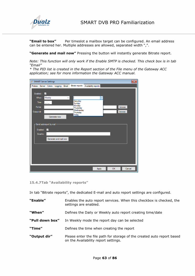
15.4.6 Tab “Bitrate reports”
In tab “Bitrate reports”, the dedicated E-mail and auto report settings are configured.
“Enable” Enables the auto report services. When this checkbox is checked, the
settings are enabled.
“When” Defines the Daily or Weekly auto report creating time/date
“Pull down box” In Weekly mode the report day can be selected
“Time” Defines the time when creating the report.
“Pid list” Please enter the file path of the created* Pid list
“Output dir” Please enter the file path for storage of the created auto report based
on the Pid list.
“Pid list” Please enter the file path of the created Pid list
“Generate now” Press button to overwrite the time function and create instantly a Bitrate report according the Pid list.
“Send autoreport by mail” When Enabled the system will send an Email to the address
(es) in the email to box.
Page 63 of 86
SMART DVB PRO Familiarization
“Email to box” Per timeslot a mailbox target can be configured. An email address
can be entered her. Multiple addresses are allowed, separated width “,”.
“Generate and mail now” Pressing the button will instantly generate Bitrate report.
Note: This function will only work if the Enable SMTP is checked. This check box is in tab “Email”
* The PID list is created in the Report section of the File menu of the Gateway ACC
application; see for more information the Gateway ACC manual.
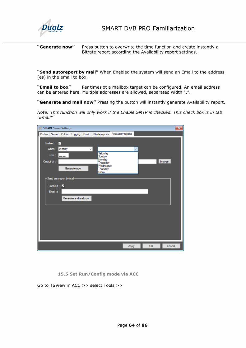
15.4.7 Tab “Availability reports”
In tab “Bitrate reports”, the dedicated E-mail and auto report settings are configured.
“Enable” Enables the auto report services. When this checkbox is checked, the
settings are enabled.
“When” Defines the Daily or Weekly auto report creating time/date
“Pull down box” In Weekly mode the report day can be selected
“Time” Defines the time when creating the report
“Output dir” Please enter the file path for storage of the created auto report based
on the Availability report settings.
Page 64 of 86
SMART DVB PRO Familiarization
“Generate now” Press button to overwrite the time function and create instantly a
Bitrate report according the Availability report settings.
“Send autoreport by mail” When Enabled the system will send an Email to the address
(es) in the email to box.
“Email to box” Per timeslot a mailbox target can be configured. An email address
can be entered here. Multiple addresses are allowed, separated width “,”.
“Generate and mail now” Pressing the button will instantly generate Availability report.
Note: This function will only work if the Enable SMTP is checked. This check box is in tab
“Email”
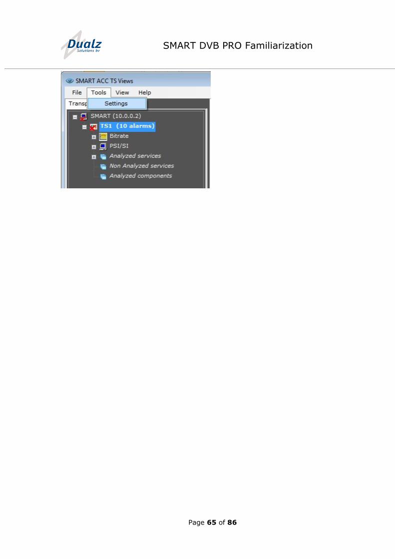
15.5 Set Run/Config mode via ACC
Go to TSView in ACC >> select Tools >>
Page 65 of 86
SMART DVB PRO Familiarization
Page 66 of 86
SMART DVB PRO Familiarization
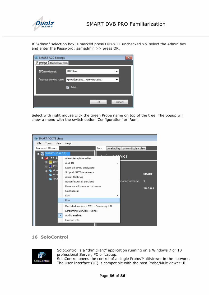
If "Admin" selection box is marked press OK>> IF unchecked >> select the Admin box
and enter the Password: samadmin >> press OK.
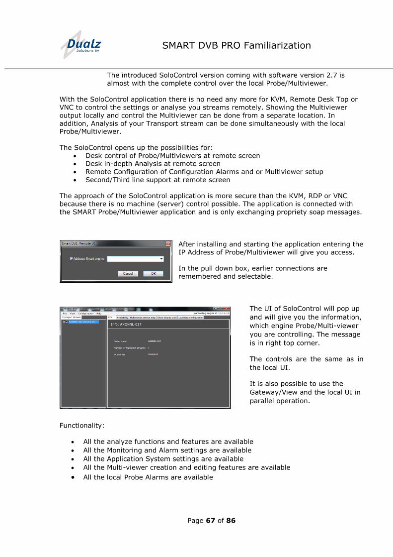
Select with right mouse click the green Probe name on top of the tree. The popup will
show a menu with the switch option ‘Configuration’ or ‘Run’.
16 SoloControl
SoloControl is a “thin client” application running on a Windows 7 or 10
professional Server, PC or Laptop. SoloControl opens the control of a single Probe/Multiviewer in the network.
The User Interface (UI) is compatible with the host Probe/Multiviewer UI.
Page 67 of 86
SMART DVB PRO Familiarization
The introduced SoloControl version coming with software version 2.7 is
almost with the complete control over the local Probe/Multiviewer.
With the SoloControl application there is no need any more for KVM, Remote Desk Top or
VNC to control the settings or analyse you streams remotely. Showing the Multiviewer
output locally and control the Multiviewer can be done from a separate location. In
addition, Analysis of your Transport stream can be done simultaneously with the local Probe/Multiviewer.
The SoloControl opens up the possibilities for:
Desk control of Probe/Multiviewers at remote screen Desk in-depth Analysis at remote screen
Remote Configuration of Configuration Alarms and or Multiviewer setup
Second/Third line support at remote screen
The approach of the SoloControl application is more secure than the KVM, RDP or VNC
because there is no machine (server) control possible. The application is connected with
the SMART Probe/Multiviewer application and is only exchanging propriety soap messages.
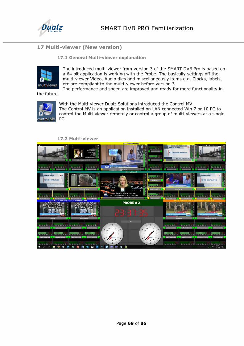
After installing and starting the application entering the
IP Address of Probe/Multiviewer will give you access.
In the pull down box, earlier connections are
remembered and selectable.
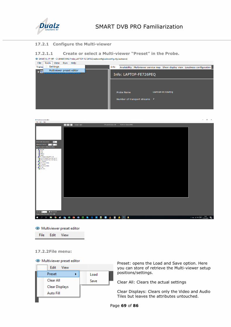
The UI of SoloControl will pop up
and will give you the information,
which engine Probe/Multi-viewer
you are controlling. The message
is in right top corner.
The controls are the same as in
the local UI.
It is also possible to use the
Gateway/View and the local UI in
parallel operation.
Functionality:
All the analyze functions and features are available
All the Monitoring and Alarm settings are available
All the Application System settings are available
All the Multi-viewer creation and editing features are available
All the local Probe Alarms are available
Page 68 of 86
SMART DVB PRO Familiarization
17 Multi-viewer (New version)
17.1 General Multi-viewer explanation
The introduced multi-viewer from version 3 of the SMART DVB Pro is based on
a 64 bit application is working with the Probe. The basically settings off the
multi-viewer Video, Audio tiles and miscellaneously items e.g. Clocks, labels,
etc are compliant to the multi-viewer before version 3.
The performance and speed are improved and ready for more functionality in the future.
With the Multi-viewer Dualz Solutions introduced the Control MV.
The Control MV is an application installed on LAN connected Win 7 or 10 PC to control the Multi-viewer remotely or control a group of multi-viewers at a single
PC
17.2 Multi-viewer
Page 69 of 86
SMART DVB PRO Familiarization
17.2.1 Configure the Multi-viewer
17.2.1.1 Create or select a Multi-viewer “Preset” in the Probe.
17.2.2 File menu:
Preset: opens the Load and Save option. Here
you can store of retrieve the Multi-viewer setup positions/settings.
Clear All: Clears the actual settings
Clear Displays: Clears only the Video and Audio
Tiles but leaves the attributes untouched.
Page 70 of 86
SMART DVB PRO Familiarization
Auto Fill: Enables a menu to have a fast Multi-viewer setup
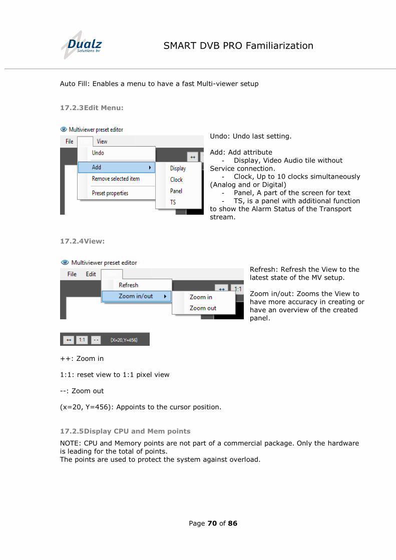
17.2.3 Edit Menu:
Undo: Undo last setting.
Add: Add attribute
- Display, Video Audio tile without
Service connection. - Clock, Up to 10 clocks simultaneously
(Analog and or Digital)
- Panel, A part of the screen for text
- TS, is a panel with additional function to show the Alarm Status of the Transport
stream.
17.2.4 View:
Refresh: Refresh the View to the
latest state of the MV setup.
Zoom in/out: Zooms the View to
have more accuracy in creating or
have an overview of the created
panel.
++: Zoom in
1:1: reset view to 1:1 pixel view
--: Zoom out
(x=20, Y=456): Appoints to the cursor position.
17.2.5 Display CPU and Mem points
NOTE: CPU and Memory points are not part of a commercial package. Only the hardware
is leading for the total of points.
The points are used to protect the system against overload.
Page 71 of 86
SMART DVB PRO Familiarization
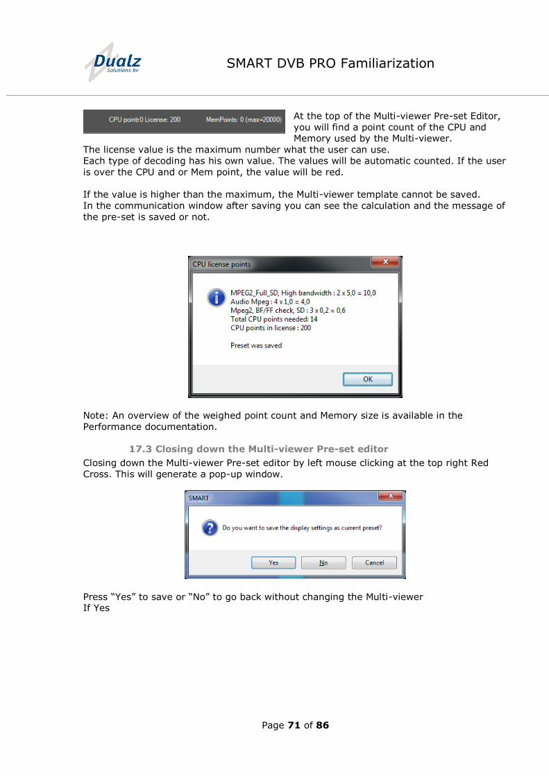
At the top of the Multi-viewer Pre-set Editor,
you will find a point count of the CPU and Memory used by the Multi-viewer.
The license value is the maximum number what the user can use.
Each type of decoding has his own value. The values will be automatic counted. If the user
is over the CPU and or Mem point, the value will be red.
If the value is higher than the maximum, the Multi-viewer template cannot be saved.
In the communication window after saving you can see the calculation and the message of
the pre-set is saved or not.
Note: An overview of the weighed point count and Memory size is available in the
Performance documentation.
17.3 Closing down the Multi-viewer Pre-set editor
Closing down the Multi-viewer Pre-set editor by left mouse clicking at the top right Red
Cross. This will generate a pop-up window.
Press “Yes” to save or “No” to go back without changing the Multi-viewer If Yes
Page 72 of 86
SMART DVB PRO Familiarization
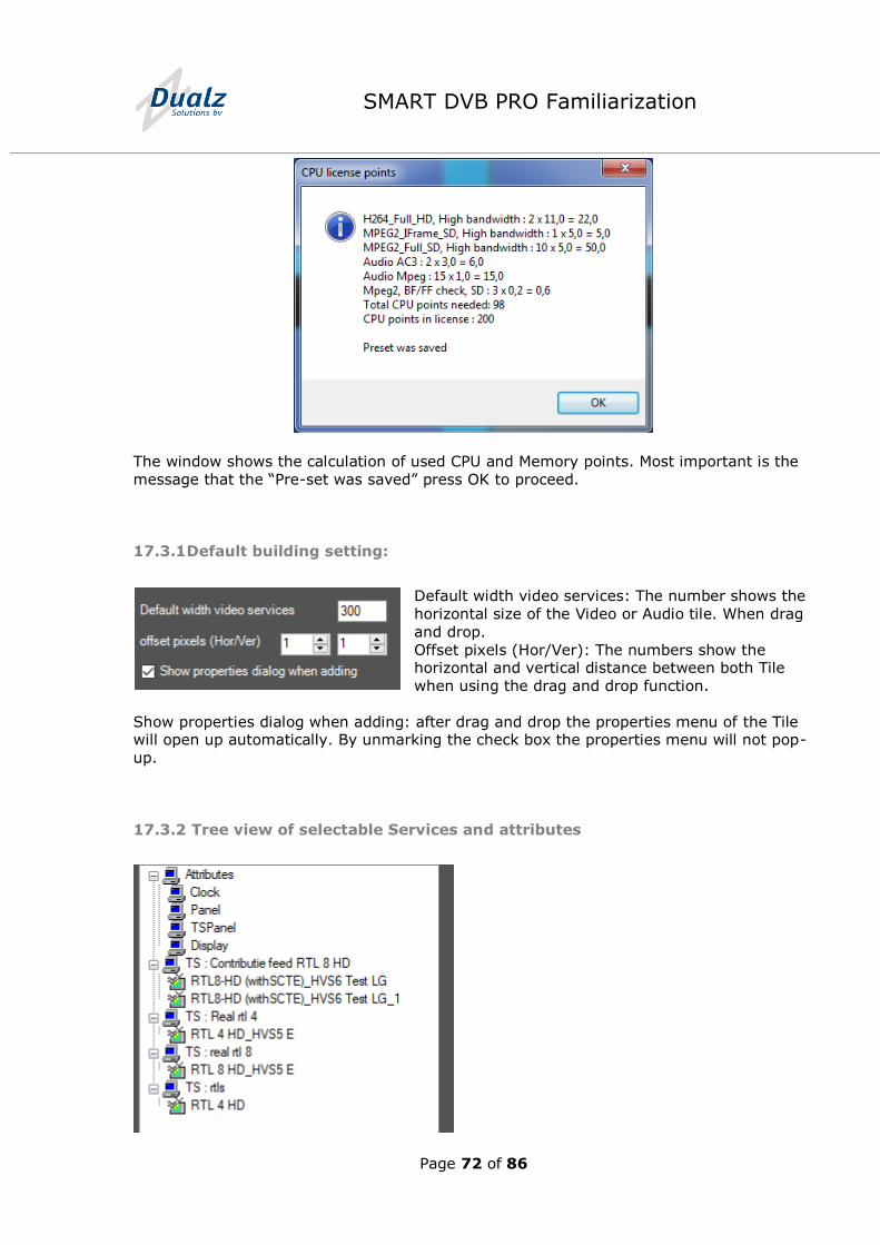
The window shows the calculation of used CPU and Memory points. Most important is the
message that the “Pre-set was saved” press OK to proceed.
17.3.1 Default building setting:
Default width video services: The number shows the
horizontal size of the Video or Audio tile. When drag
and drop.
Offset pixels (Hor/Ver): The numbers show the horizontal and vertical distance between both Tile
when using the drag and drop function.
Show properties dialog when adding: after drag and drop the properties menu of the Tile will open up automatically. By unmarking the check box the properties menu will not pop-
up.
17.3.2 Tree view of selectable Services and attributes
Page 73 of 86
SMART DVB PRO Familiarization
17.3.3 Hide selected Services
- Marking the checkbox will take out the all ready selected Service in the Tree View.
This will help you creating the Multi-viewer
with the drag and drop functionality.
- The Display Windows Size (wxh): shows the Multi-viewer screen size setting in the
monitors in the Tools/settings/monitor menu.
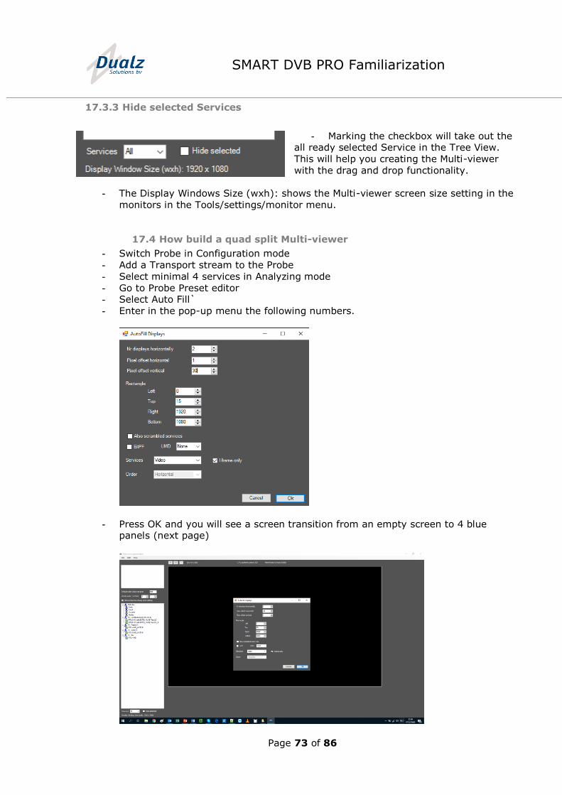
17.4 How build a quad split Multi-viewer
- Switch Probe in Configuration mode
- Add a Transport stream to the Probe
- Select minimal 4 services in Analyzing mode
- Go to Probe Preset editor - Select Auto Fill`
- Enter in the pop-up menu the following numbers.
- Press OK and you will see a screen transition from an empty screen to 4 blue panels (next page)
Page 74 of 86
SMART DVB PRO Familiarization
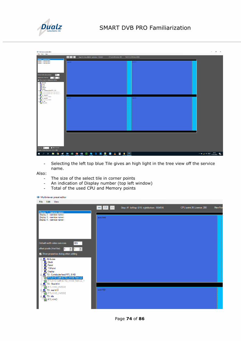
- Selecting the left top blue Tile gives an high light in the tree view off the service
name.
Also: - The size of the select tile in corner points
- An indication of Display number (top left window)
- Total of the used CPU and Memory points

Page 75 of 86
SMART DVB PRO Familiarization
- Close the Preset editor View by selecting the red cross in the right top corner
- Press Yes for saving the preset to the Multi-viewer - Press OK at the question of the CPU Licenses point overview pop-up
- Start the Multi-viewer application by double mouse click on the
desktop.
The Multi-viewer will appear directly with the selected four video source including the Audio bars (see next picture of the quad splitt)
17.5 Adjusting the Multi-viewer display settings.
17.5.1 To customize settings in the Multi-viewer some settings:
Some settings are globally arranged and some are arranged per Tile
17.5.1.1 Globally setting customizable in a Json file structure.
The Json structure settings is only for expert users and in the ANNEX 1 of this document
17.5.1.2 Tile depending user settings.
- In the Pre-set editor at the probe you can select:
o By double mouse click at the blue Tile representation
the properties menu will popup
Page 76 of 86
SMART DVB PRO Familiarization
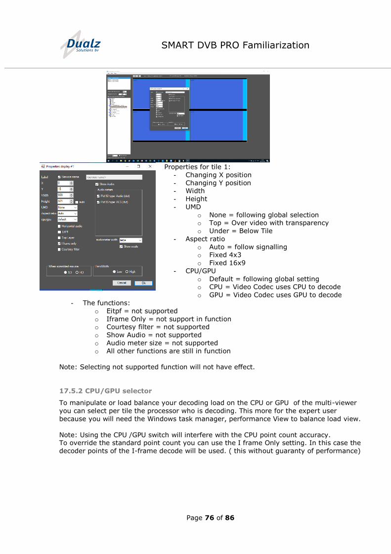
Properties for tile 1:
- Changing X position
- Changing Y position - Width
- Height
- UMD
o None = following global selection o Top = Over video with transparency
o Under = Below Tile
- Aspect ratio
o Auto = follow signalling o Fixed 4x3
o Fixed 16x9
- CPU/GPU
o Default = following global setting o CPU = Video Codec uses CPU to decode
o GPU = Video Codec uses GPU to decode
- The functions:
o Eitpf = not supported
o Iframe Only = not support in function o Courtesy filter = not supported
o Show Audio = not supported
o Audio meter size = not supported
o All other functions are still in function
Note: Selecting not supported function will not have effect.
17.5.2 CPU/GPU selector
To manipulate or load balance your decoding load on the CPU or GPU of the multi-viewer
you can select per tile the processor who is decoding. This more for the expert user
because you will need the Windows task manager, performance View to balance load view.
Note: Using the CPU /GPU switch will interfere with the CPU point count accuracy. To override the standard point count you can use the I frame Only setting. In this case the
decoder points of the I-frame decode will be used. ( this without guaranty of performance)
Page 77 of 86
SMART DVB PRO Familiarization
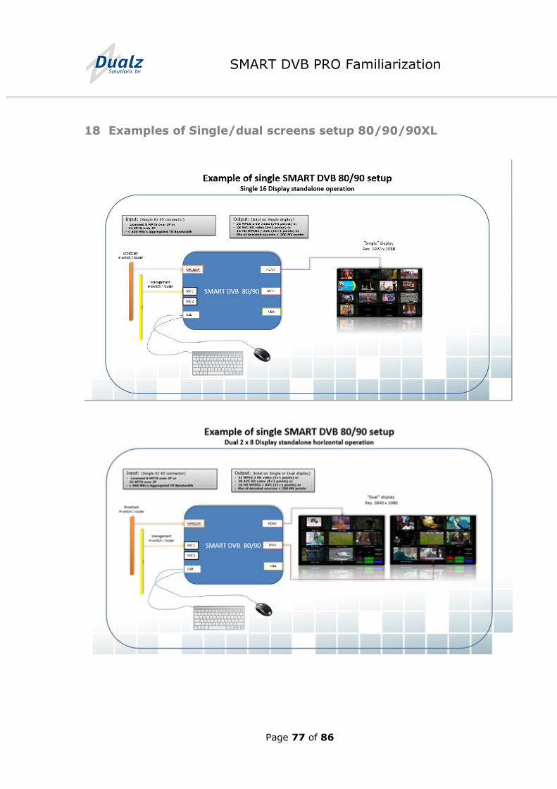
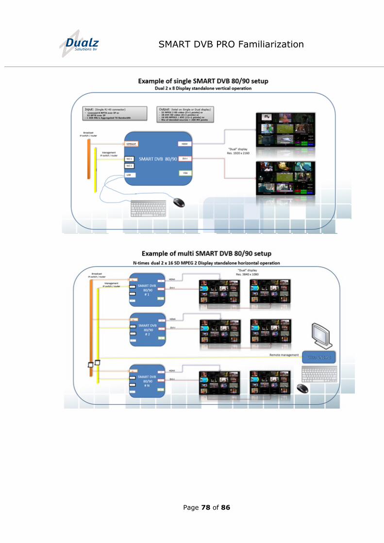
18 Examples of Single/dual screens setup 80/90/90XL
Page 78 of 86
SMART DVB PRO Familiarization
Page 79 of 86
SMART DVB PRO Familiarization
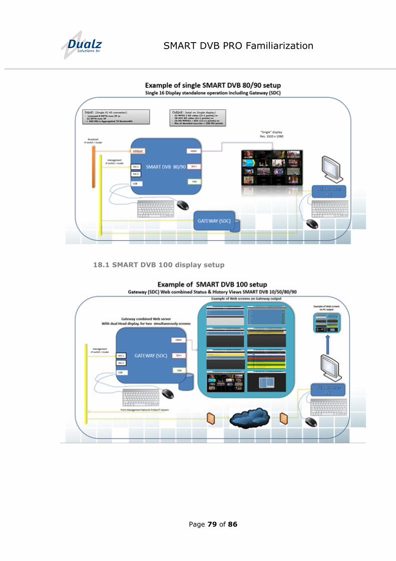
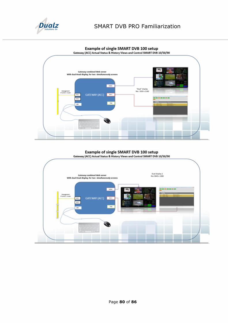
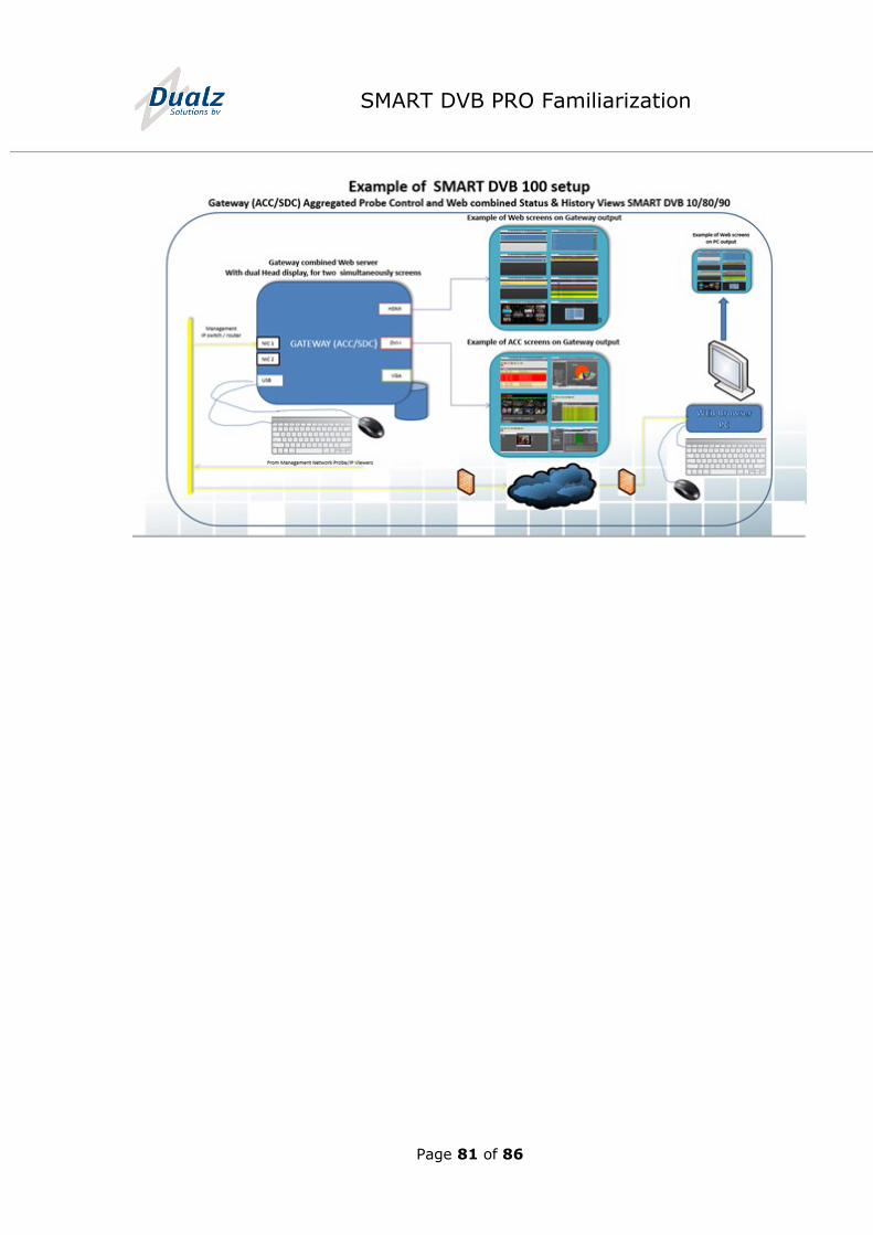
18.1 SMART DVB 100 display setup
Page 80 of 86
SMART DVB PRO Familiarization
Page 81 of 86
SMART DVB PRO Familiarization
Page 82 of 86
SMART DVB PRO Familiarization
19 DVB Tables
19.1 Table
ID values
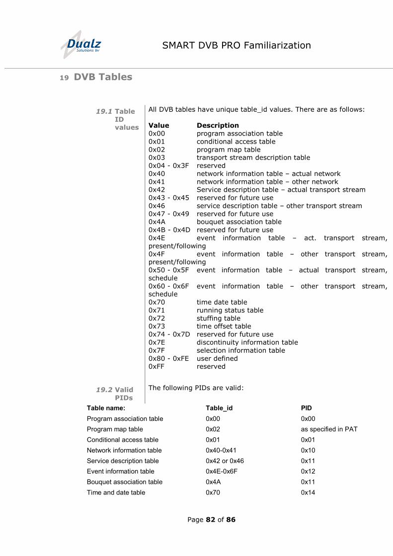
All DVB tables have unique table_id values. There are as follows:
Value Description
0x00 program association table
0x01 conditional access table
0x02 program map table 0x03 transport stream description table
0x04 - 0x3F reserved
0x40 network information table – actual network
0x41 network information table – other network 0x42 Service description table – actual transport stream
0x43 - 0x45 reserved for future use
0x46 service description table – other transport stream
0x47 - 0x49 reserved for future use 0x4A bouquet association table
0x4B - 0x4D reserved for future use
0x4E event information table – act. transport stream,
present/following
0x4F event information table – other transport stream, present/following
0x50 - 0x5F event information table – actual transport stream,
schedule
0x60 - 0x6F event information table – other transport stream, schedule
0x70 time date table
0x71 running status table
0x72 stuffing table 0x73 time offset table
0x74 - 0x7D reserved for future use
0x7E discontinuity information table
0x7F selection information table
0x80 - 0xFE user defined 0xFF reserved
19.2 Valid
PIDs
The following PIDs are valid:
Table name: Table_id PID
Program association table 0x00 0x00
Program map table 0x02 as specified in PAT
Conditional access table 0x01 0x01
Network information table 0x40-0x41 0x10
Service description table 0x42 or 0x46 0x11
Event information table 0x4E-0x6F 0x12
Bouquet association table 0x4A 0x11
Time and date table 0x70 0x14
Page 83 of 86
SMART DVB PRO Familiarization
Time offset table 0x73 0x14
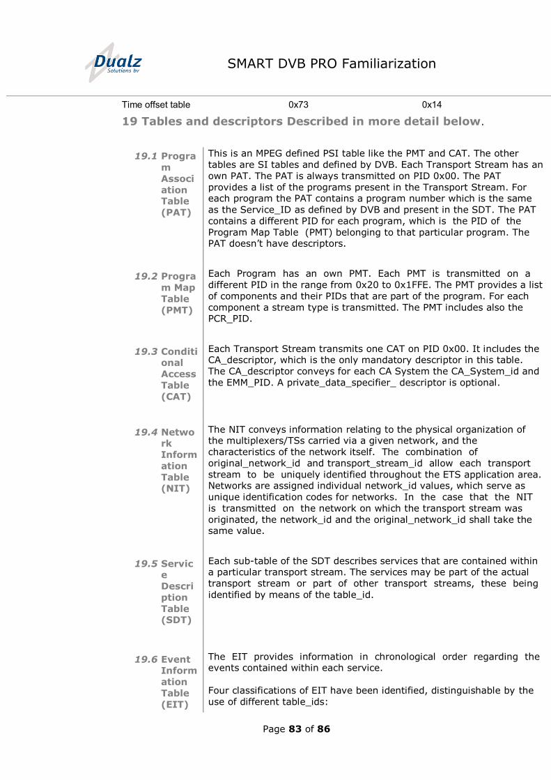
19 Tables and descriptors Described in more detail below.
19.1 Progra
m
Associ
ation Table
(PAT)
This is an MPEG defined PSI table like the PMT and CAT. The other
tables are SI tables and defined by DVB. Each Transport Stream has an
own PAT. The PAT is always transmitted on PID 0x00. The PAT
provides a list of the programs present in the Transport Stream. For each program the PAT contains a program number which is the same
as the Service_ID as defined by DVB and present in the SDT. The PAT
contains a different PID for each program, which is the PID of the
Program Map Table (PMT) belonging to that particular program. The PAT doesn’t have descriptors.
19.2 Progra
m Map
Table
(PMT)
Each Program has an own PMT. Each PMT is transmitted on a
different PID in the range from 0x20 to 0x1FFE. The PMT provides a list
of components and their PIDs that are part of the program. For each
component a stream type is transmitted. The PMT includes also the PCR_PID.
19.3 Conditional
Access
Table
(CAT)
Each Transport Stream transmits one CAT on PID 0x00. It includes the CA_descriptor, which is the only mandatory descriptor in this table.
The CA_descriptor conveys for each CA System the CA_System_id and
the EMM_PID. A private_data_specifier_ descriptor is optional.
19.4 Network
Inform
ation
Table (NIT)
The NIT conveys information relating to the physical organization of the multiplexers/TSs carried via a given network, and the
characteristics of the network itself. The combination of
original_network_id and transport_stream_id allow each transport
stream to be uniquely identified throughout the ETS application area. Networks are assigned individual network_id values, which serve as
unique identification codes for networks. In the case that the NIT
is transmitted on the network on which the transport stream was
originated, the network_id and the original_network_id shall take the same value.
19.5 Service
Descri
ption
Table (SDT)
Each sub-table of the SDT describes services that are contained within a particular transport stream. The services may be part of the actual
transport stream or part of other transport streams, these being
identified by means of the table_id.
19.6 Event Inform
ation
Table
(EIT)
The EIT provides information in chronological order regarding the events contained within each service.
Four classifications of EIT have been identified, distinguishable by the
use of different table_ids:
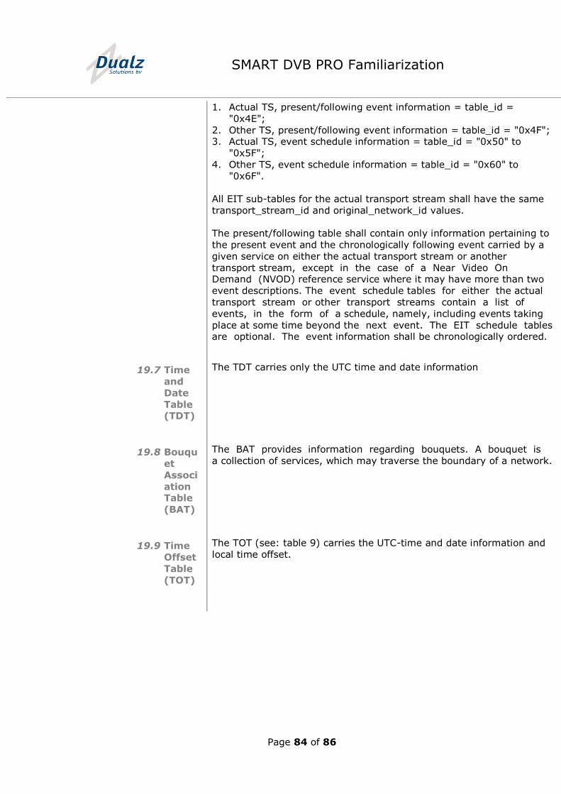
Page 84 of 86
SMART DVB PRO Familiarization
1. Actual TS, present/following event information = table_id =
"0x4E";
2. Other TS, present/following event information = table_id = "0x4F"; 3. Actual TS, event schedule information = table_id = "0x50" to
"0x5F";
4. Other TS, event schedule information = table_id = "0x60" to
"0x6F".
All EIT sub-tables for the actual transport stream shall have the same
transport_stream_id and original_network_id values.
The present/following table shall contain only information pertaining to
the present event and the chronologically following event carried by a
given service on either the actual transport stream or another
transport stream, except in the case of a Near Video On Demand (NVOD) reference service where it may have more than two
event descriptions. The event schedule tables for either the actual
transport stream or other transport streams contain a list of
events, in the form of a schedule, namely, including events taking
place at some time beyond the next event. The EIT schedule tables are optional. The event information shall be chronologically ordered.
19.7 Time
and
Date
Table (TDT)
The TDT carries only the UTC time and date information
19.8 Bouqu
et
Associ
ation Table
(BAT)
The BAT provides information regarding bouquets. A bouquet is
a collection of services, which may traverse the boundary of a network.
19.9 Time
Offset
Table
(TOT)
The TOT (see: table 9) carries the UTC-time and date information and
local time offset.
Page 85 of 86
SMART DVB PRO Familiarization
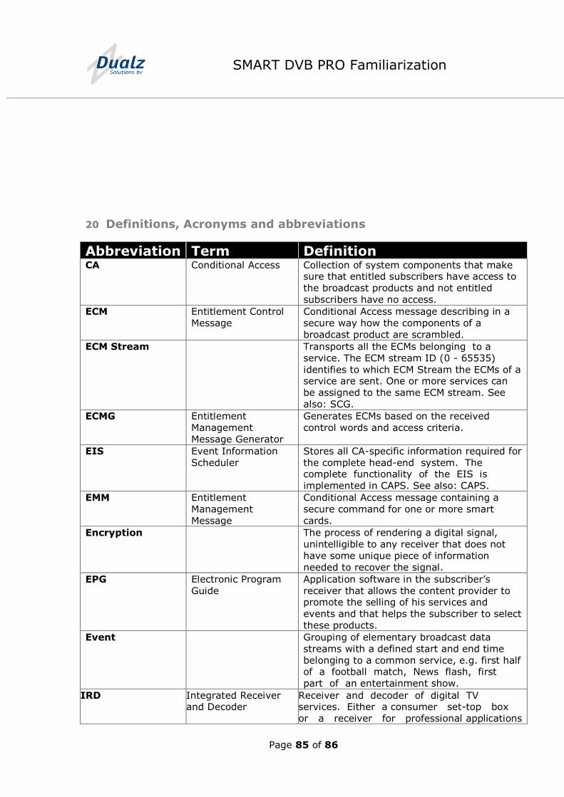
20 Definitions, Acronyms and abbreviations
Abbreviation Term Definition CA Conditional Access Collection of system components that make
sure that entitled subscribers have access to
the broadcast products and not entitled
subscribers have no access.
ECM Entitlement Control
Message
Conditional Access message describing in a
secure way how the components of a
broadcast product are scrambled.
ECM Stream Transports all the ECMs belonging to a
service. The ECM stream ID (0 - 65535)
identifies to which ECM Stream the ECMs of a service are sent. One or more services can
be assigned to the same ECM stream. See
also: SCG.
ECMG Entitlement
Management
Message Generator
Generates ECMs based on the received
control words and access criteria.
EIS Event Information
Scheduler
Stores all CA-specific information required for
the complete head-end system. The complete functionality of the EIS is
implemented in CAPS. See also: CAPS.
EMM Entitlement
Management
Message
Conditional Access message containing a
secure command for one or more smart
cards.
Encryption The process of rendering a digital signal,
unintelligible to any receiver that does not
have some unique piece of information
needed to recover the signal.
EPG Electronic Program
Guide
Application software in the subscriber’s
receiver that allows the content provider to promote the selling of his services and
events and that helps the subscriber to select
these products.
Event Grouping of elementary broadcast data
streams with a defined start and end time
belonging to a common service, e.g. first half of a football match, News flash, first
part of an entertainment show.
IRD Integrated Receiver and Decoder
Receiver and decoder of digital TV services. Either a consumer set-top box
or a receiver for professional applications
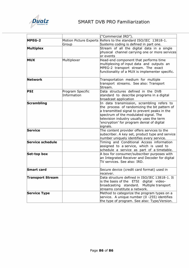
Page 86 of 86
SMART DVB PRO Familiarization
(“Commercial IRD”).
MPEG-2 Motion Picture Experts
Group
Refers to the standard ISO/IEC 13818-1.
Systems coding is defined in part one.
Multiplex Stream of all the digital data in a single
physical channel carrying one or more services or events
MUX Multiplexer Head-end component that performs time multiplexing of input data and outputs an
MPEG-2 transport stream. The exact
functionality of a MUX is implementer specific.
Network Transportation medium for multiple
transport streams. See also: Transport Stream.
PSI Program Specific Information
Data structures defined in the DVB standard to describe programs in a digital
broadcast application
Scrambling In data transmission, scrambling refers to the process of randomizing the bit pattern of
a transmitted signal to prevent peaks in the
spectrum of the modulated signal. The
television industry usually uses the term ‘encryption’ for program denial of digital
signals.
Service The content provider offers services to the
subscriber. A key set, product type and service
number uniquely identifies every service.
Service schedule Timing and Conditional Access information
assigned to a service, which is used to
schedule a service as part of a timetable.
Set-top box A box for consumer/subscriber purposes with
an Integrated Receiver and Decoder for digital
TV services. See also: IRD.
Smart card Secure device (credit card format) used in receiver.
Transport Stream Data structure defined in ISO/IEC 13818-1. It is the basis of the ETSI digital video-
broadcasting standard. Multiple transport
streams constitute a network.
Service Type Method to categorize the program types on a
service. A unique number (0 -255) identifies
the type of program. See also: Type/Version.