Embed Size (px)
Citation preview

Influence of a permanent liner on the skin frictionof large-diameter bored piles in Hong Konggranitic saprolites
S.-C.R. Lo and K.S. Li
Abstract: The skin friction of large-diameter bored piles in Hong Kong granitic saprolite manifested high variability.The influence of one construction detail, a full-length permanent liner, is studied by examining full-scale load testresults and by numerical simulation of this construction detail. It is concluded that the use of a full-length liner willgive very low skin friction because the local method of constructing a large-diameter bored pile with a full-lengthpermanent liner leads to a significant reduction in radial stress acting on the pile–soil interface.
Key words: construction, pile, stress, skin friction, numerical simulation.
Résumé : Le frottement sur la superficie cylindrique de pieux de grands diamètres forés dans la saprolite granitique deHong Kong a montré une forte variabilité. On a étudié l’influence d’un détail de construction, soit une membranepleine longueur, en examinant les résultats d’essais de chargement à pleine échelle et par simulation numérique de cedétail de construction. On a conclu que l’utilisation de membrane à pleine longueur va donner un très faible frottementsuperficiel sur le pieu. Ceci est dû à la méthode locale de construction des pieux forés à grands diamètres avec unemembrane permanente à pleine longueur qui va conduire à une réduction significative de la contrainte radiale agissantsur l’interface sol–pieu.
Mots clés : construction, pieu, contrainte, frottement superficiel, simulation numérique.
[Traduit par la Rédaction] Lo and Li 805
1. Introduction
Hong Kong has a population in excess of six million but atotal land area, including land reclaimed from the sea, of justin excess of 1000 km2. Due to intense urban development,design decisions are often driven by land constraints. Fur-thermore, all major buildings and infrastructures have to bedesigned to resist the most severe tropical cyclone. There-fore, high column loads and large, machine-excavatedreplacement piles, such as circular bored piles or barrettes(rectangular replacement piles excavated under a bentoniteslurry), are commonplace in Hong Kong. This paper, how-ever, only addresses machine-excavated circular bored piles.
If bedrock is encountered at a depth not exceeding 40 m,conventional design procedure is to found the pile on bed-rock and relies purely on end bearing capacity. Bedrock inurbanized areas of Hong Kong is mostly granitic or volcanic,and high end bearing capacity can be achieved. Due to thespheroidal weathering process (Ruxton and Berry 1957),
however, the bedrock surface may not be clearly defined.Hence, local practice relies on the prescriptive procedures ofPractice Note PNAP-141 (Hong Kong Government 1995) is-sued by the Building Department, Hong Kong Government,in determining the founding level of a bored pile end bear-ing on rock. PNAP-141 gives an allowable bearing pressureof 5000 kPa if the founding material has a total (rock) corerecovery of no less than 85%, and the recovered cores haveunconfined compressive strength (UCS) ≥25 MPa. For amore superior rock condition (as defined in PNAP-141), anallowable bearing pressure of 7500 kPa may be used. Whenbedrock satisfying the acceptance criteria stipulated inPNAP-141 for the 5000 kPa allowable bearing pressureis excessively deep, the designer may found the pile inthe overlying completely to highly decomposed granitic orvolcanic rocks, which are soil-like materials referred to assaprolites in this paper. For such a design scenario, the axialcapacity of the bored pile will be derived mainly from skinfriction in the saprolite stratum.
Bored piles supported by skin friction in granitic saprolitehave been successfully used in Hong Kong since the early1980s, notably in the projects of Telford Gardens (Holt et al.1982) and the Island Eastern Corridor (Fraser 1985; Fraserand Kwok 1986). A number of full-scale pile tests were con-ducted in an attempt to justify the choice of design skin fric-tion values. It is pertinent to note that most of the load testdata are for granitic saprolite. The measured skin friction,however, manifested considerable variability and was, on theaverage, significantly lower than values reported in the liter-ature (Meyerhof 1976; Touma and Reese 1974; Reese and
Can. Geotech. J. 40: 793–805 (2003) doi: 10.1139/T03-028 © 2003 NRC Canada
793
Received 24 June 2002. Accepted 26 February 2003.Published on the NRC Research Press Web site athttp://cgj.nrc.ca on 5 August 2003.
S.-C.R. Lo.1 School of Civil Engineering, University of NewSouth Wales, ADFA, Canberra, ACT 2600, Australia.K.S. Li. Victor Li & Associates Ltd., Chevalier CommercialBuilding, Wang Hoi Road, Kowloon Bay, Hong Kong, andUniversity of Hong Kong, Department of Civil Engineering,Pokfulum Road, Hong Kong.
1Corresponding author (e-mail: [email protected]).
I:\cgj\CGJ40-04\T03-028.vpJuly 30, 2003 2:51:15 PM
Color profile: Generic CMYK printer profileComposite Default screen

Wright 1977; Reese and O’Neill 1988; Chang and Broms1991; Chang and Wong 1995; Tan et al. 1998). This “rela-tively lower” skin friction of bored piles in saprolite, and itshigh variability, has been examined in a number of papers.Malone et al. (1992) stated that “there appears to be no order…” in the variation of skin friction. Ng et al. (2000), basedon selected test results, suggested that skin friction of “wellconstructed” bored piles can be estimated with simple de-sign equations. Lo and Li (2000) suggested that skin frictionvalues in saprolites are sensitive to “details” of the pile in-stallation, which often did not form part of the method state-ment or construction specification. The broad objective ofthis paper is to study the possible adverse effects on skinfriction due to one particular construction detail, the use ofa full-length permanent liner. This construction detail canhave a very significant adverse effect on skin friction. Theperformance of four full-scale test piles constructed with lin-ers in granitic saprolites was examined. The installation of apermanent liner in bored pile construction and its effects onskin friction were also simulated numerically.
2. Ground conditions
The subsurface conditions overlying granitic bedrock canbe simplified as shown in Fig. 1a. Bedrock is overlain byhighly decomposed granite, which transitions into com-pletely decomposed granite. Both materials are soil-like ma-terials that retain some of the fabric of the parent rock, withthe possible exception of the top few metres of the com-pletely decomposed zone (Lumb 1983; Au 1998). Thesestructured soils are collectively referred to as saprolites (or,more precisely, granitic saprolites), and this is the term usedin this paper. Due to the spheroidal weathering process(Ruxton and Berry 1957), core stones may be left in thesaprolite stratum. The engineering characteristics of graniticsaprolites are well documented in the milestone publicationsof Lumb (1962a, 1983), and the findings of other research-ers are summarized in Au (1998). The engineering proper-ties of granitic saprolites are briefly described here. Graniticsaprolite is a silty clayey sand with a standard penetrationtest (SPT) blow count value in excess of 40 for completelydecomposed granite and increasing to 200 for highly decom-posed granite. The mass permeability is of the order of 10–5
to 10–7 m/s (Lumb 1962a, 1962b, 1975; GEO 1993). A sec-ondary porosity system is likely to be present in saprolites(Au 1990, 1998), and this further increases the drainage rateof small zones. Therefore, pile design is based on drainedbehaviour. As reported in Au (1998), granitic saprolite hasa failure surface consisting of two zones as illustrated inFig. 1b: a curved zone with the shape of a “bump” at a lowereffective confining stress, and a linear zone at a higher effec-tive confining stress. Granitic saprolite may have a small ef-fective cohesion, but it is still a matter of debate whether thevalues reported in the literature are partly or largely due tolinearizing curved failure surfaces. It is commonly assumedthat granitic saprolite is dilatant at failure, but Au (1998)suggested that this is conditional upon the failure stress statelocated on the curved part of the failure surface. These be-haviour patterns are consistent with those of structured soils(Leroueil and Vaughan 1990). The top zone of the com-pletely decomposed zone may become a structureless resid-
ual soil with a higher fines content (Irfan 1996). Thisstructureless soil, usually only a few metres thick, is some-times referred to as residual soil or “red earth” (Lumb1962a, 1965) and has lower SPT values. The terminologyused by local engineers (and to some extent researchers) todescribe the soil derived from in situ decomposition of gran-ite can be confusing. It is noted that the term decomposedgranite (DG) is often used interchangeably with saprolite inpile design, although the latter, strictly speaking, includesthe structureless residual soil. Occasionally, the term decom-posed granite is also used quite misleadingly to denote allgeomaterials, from rock-like materials to structureless soil,derived from the in situ decomposition of granite. The resid-ual soil is usually covered with weaker superficial deposits.The superficial deposits may be colluvium and topsoil in thehilly areas or old alluvium, marine deposits, and fill in thereclaimed areas. It is not uncommon to encounter superficialdeposits with a total thickness in excess of 20 m. The watertable is generally encountered prior to reaching foundinglevel, and it is generally not feasible to dewater the pileexcavation unless the complete pile periphery is grouted.Hence most machine-excavated bored piles were constructedunder water. For a variety of practical reasons, including thepossibility of negative friction drag-down from the superfi-cial deposits due to subsequent adjoining developments, theskin friction support from the superficial deposits is not in-cluded in calculating friction capacity of a large-diameterbored pile.
3. Pile construction
Large-diameter bored piles in Hong Kong are mostlyexcavated either by hammer grabbing (HG) or reverse circu-lation drilling (RCD). These two methods of installation en-able excavation of 3 m diameter piles to depths exceeding70 m. To ensure the required pile penetration into the sapro-lite stratum, it is common practice to sink a borehole (withSPT taken) in the saprolite stratum at a pile or column posi-tion.
3.1 Pile excavation techniquesThe HG method is sometimes referred to as the casing
method. This term will not be used in this paper, however, asboth HG and RCD involve the sinking of an excavation cas-ing. In the HG method, a heavy-duty excavation casing issunk by an oscillator, rotator, or vibrating hammer, and thesoil inside the casing is excavated by a heavy grab (Fig. 2a).Because of the size of the bored pile and the strength of theundisturbed saprolites, excavation and sinking of the casingmust proceed in parallel. This pile excavation technique canbe used for superficial deposits, old alluvium, residual soil,or saprolite. In principle, the casing toe should be kept aheadof the excavation. For the RCD method (Fig. 2b), a casing issunk using an oscillator or techniques similar to HG untilsaprolite is encountered. Pile excavation is then conductedusing a special drill rig and the excavated materials flushedback to the surface by the reverse circulation technique. Thedrill shaft in the saprolite stratum is uncased. The drillingfluid, in addition to being a carrier for flushing the excavatedmaterial, provides a controlled positive differential pressureto support the uncased pile excavation. The drill fluid can be
© 2003 NRC Canada
794 Can. Geotech. J. Vol. 40, 2003
I:\cgj\CGJ40-04\T03-028.vpJuly 30, 2003 2:51:15 PM
Color profile: Generic CMYK printer profileComposite Default screen

water (Au and Lo 1993) or bentonite slurry. The pile shaft inthe saprolite stratum may be partly excavated by HG butcompleted with RCD. The excavation casing will be recov-ered either during or after concreting, and this will leave avery rough pile surface, as attested by the many bored pilesexposed in deep basement or cut-and-cover tunnel construc-tion in Hong Kong.
3.2 Permanent linerIrrespective of whether the HG or RCD method is used, a
corrugated permanent (sacrificial) thin steel liner for the up-
per (weaker) strata may be installed as illustrated in Fig. 3afor constructability reasons such as enabling the use of over-sized excavation casing to facilitate the removal of boulders.The liner also provides a gap for the installation of a sliplayer (such as bentonite) for reducing potential negative fric-tion drag-down from the fill and marine deposit stratacaused by adjoining developments. This liner may be ex-tended along the full length of the pile (and sitting on thebase of the pile excavation) as illustrated in Fig. 3b simplyfor the sake of easier installation and (or) to avoid mixing ofconcrete with groundwater in the overbreaks of the saprolite
© 2003 NRC Canada
Lo and Li 795
Fig. 1. (a) Typical subsurface conditions. (b) Failure surface of granitic saprolite (schematic).
Fig. 2. Construction methods: (a) hammer grabbing; (b) reverse circulation drilling. GL, ground level; WT, water table.
I:\cgj\CGJ40-04\T03-028.vpJuly 30, 2003 2:51:15 PM
Color profile: Generic CMYK printer profileComposite Default screen

stratum. For a pile end bearing on bedrock, the provision ofa full-length permanent liner may be considered by some en-gineers as a good construction practice, since it eliminatesthe possibility of soil slumping into the pile base.
For piles founded in saprolites, a full-length permanentliner always creates a temporary annular void. This gap(void) is usually 100–200 mm. The tremie concrete may notflow up into this annulus space. It is considered that thesaprolite in the vicinity of a pile will have its true cohesiondestroyed by pile construction and will collapse into the an-nular void.
4. Case histories
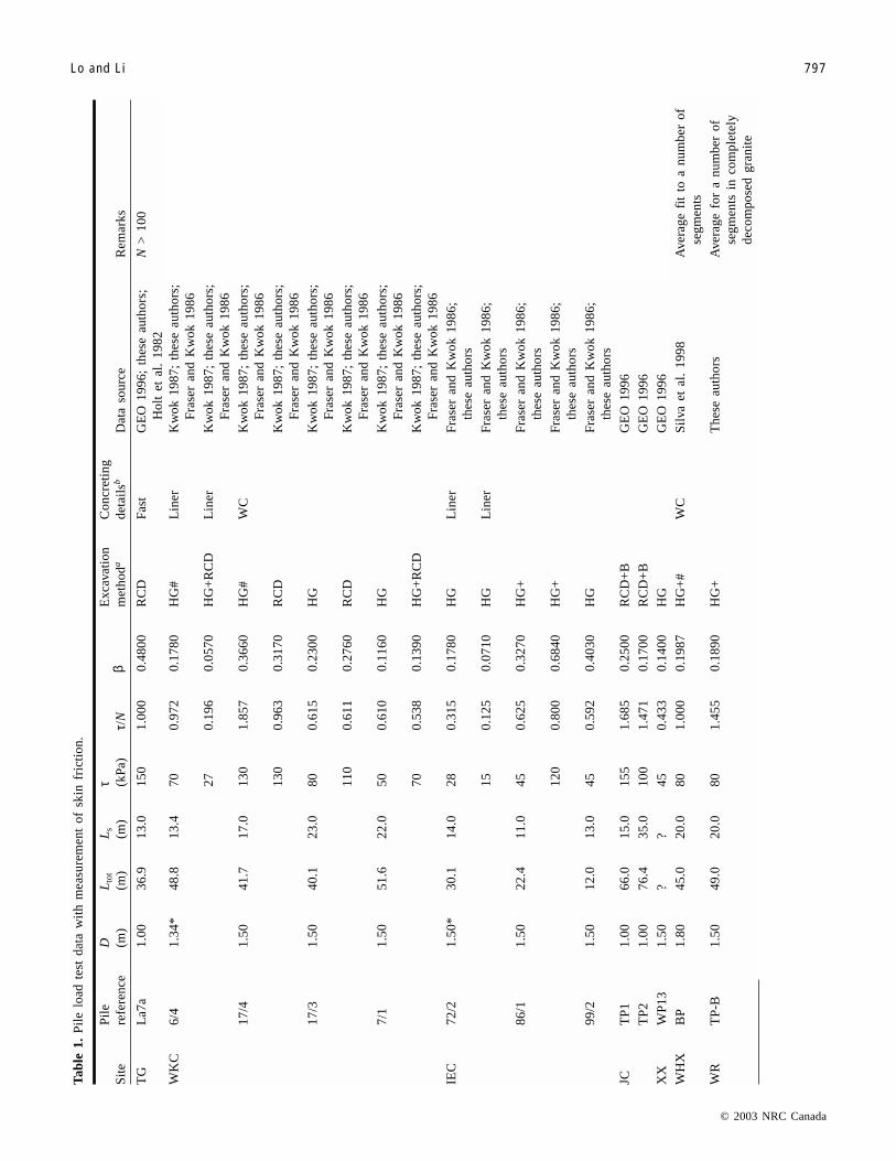
4.1 Data baseThe authors examined 22 large-diameter bored pile load
test results from 10 sites (Lo and Li 1999, 2000). All loadtests were conducted with a maintained load. The test resultswere analysed with respect to τ f, τ f /N, and β, where τ f is themeasured skin friction, N is the SPT value, and β is the de-sign parameter of the beta design method expressed as fol-lows:
[1] τ β σf vo= ⋅ ′
where σvo′ is the effective vertical stress prior to pile installa-tion. In the interpretation of load test results, τ f, N, andσvo′ are average values over an instrumented pile segment.The key data for these test piles are listed in Tables 1 and 2.Test piles listed in Table 1 were instrumented with straingauges for measurement of skin friction; the piles listedin Table 2 were not instrumented with strain gauges, butthe average skin friction can be estimated from the load–settlement curves based on Poulos and Davies (1980). Forthe sake of completeness, these load test results are brieflydiscussed in Appendix A. The measured skin friction in the
saprolite stratum (i.e., data from Table 1) can be character-ized by the statistical attributes as summarized in Table 3A.
The statistical attributes of the measured skin friction, interms of both variability and mean value, can be notably im-proved if bored piles constructed with a full-length perma-nent liner were excluded from the data base. These improvedstatistical attributes are listed in Table 3B. As discussed inAppendix A, however, Table 3B still gives skin friction val-ues that, on average, are significantly less than those givenby common design methods (Meyerhof 1976; Reese andWright 1977; Touma and Reese 1974; Reese and O’Neill1988).
4.2 Performance of piles constructed with full-lengthpermanent liners
The data base contained four piles (three sites) con-structed with permanent full-length liners. All four pilesmanifested extremely low skin friction values and may beviewed as outliers of the data base. Therefore, these fourload test results are examined in detail in the following sec-tions.
4.2.1 Western end of the IEC stage 1At the western end of the IEC stage 1 project, near Cause-
way Bay, two instrumented piles (piles 13/4 and 10/5) wereconstructed with a full-length permanent liner and loadtested in the early 1980s. Pile 13/4 was constructed by HGwithin a 1.5 m diameter excavation casing. The diameter ofthe liner was 1.2 m. Pile 10/5 was constructed by RCD,however, within a 1.7 m diameter casing and using a 1.5 mdiameter liner. The ground conditions penetrated by thesetwo piles are presented in Fig. 4. As reported in Fraser(1985), τ f values of these two piles were extremely low andonly the skin friction over the complete length of pile em-bedded in the saprolite stratum could be inferred. For pile13/4, the maximum test load was 10 MN and the skin fric-
© 2003 NRC Canada
796 Can. Geotech. J. Vol. 40, 2003
Fig. 3. Permanent liner in bored pile construction: (a) liner over superficial deposits; (b) full-length liner.
I:\cgj\CGJ40-04\T03-028.vpJuly 30, 2003 2:51:16 PM
Color profile: Generic CMYK printer profileComposite Default screen
© 2003 NRC Canada
Lo and Li 797
Sit
eP
ile
refe
renc
eD (m
)L
tot
(m)
Ls
(m)
τ (kPa
)τ/
Nβ
Exc
avat
ion
met
hoda
Con
cret
ing
deta
ilsb
Dat
aso
urce
Rem
arks
TG
La7
a1.
0036
.913
.015
01.
000
0.48
00R
CD
Fast
GE
O19
96;
thes
eau
thor
s;H
olt
etal
.19
82N
>10
0
WK
C6/
41.
34*
48.8
13.4
700.
972
0.17
80H
G#
Lin
erK
wok
1987
;th
ese
auth
ors;
Fra
ser
and
Kw
ok19
86
270.
196
0.05
70H
G+
RC
DL
iner
Kw
ok19
87;
thes
eau
thor
s;F
rase
ran
dK
wok
1986
17/4
1.50
41.7
17.0
130
1.85
70.
3660
HG
#W
CK
wok
1987
;th
ese
auth
ors;
Fra
ser
and
Kw
ok19
86
130
0.96
30.
3170
RC
DK
wok
1987
;th
ese
auth
ors;
Fra
ser
and
Kw
ok19
86
17/3
1.50
40.1
23.0
800.
615
0.23
00H
GK
wok
1987
;th
ese
auth
ors;
Fra
ser
and
Kw
ok19
86
110
0.61
10.
2760
RC
DK
wok
1987
;th
ese
auth
ors;
Fra
ser
and
Kw
ok19
86
7/1
1.50
51.6
22.0
500.
610
0.11
60H
GK
wok
1987
;th
ese
auth
ors;
Fra
ser
and
Kw
ok19
86
700.
538
0.13
90H
G+
RC
DK
wok
1987
;th
ese
auth
ors;
Fra
ser
and
Kw
ok19
86
IEC
72/2
1.50
*30
.114
.028
0.31
50.
1780
HG
Lin
erF
rase
ran
dK
wok
1986
;th
ese
auth
ors
150.
125
0.07
10H
GL
iner
Fra
ser
and
Kw
ok19
86;
thes
eau
thor
s
86/1
1.50
22.4
11.0
450.
625
0.32
70H
G+
Fra
ser
and
Kw
ok19
86;
thes
eau
thor
s
120
0.80
00.
6840
HG
+F
rase
ran
dK
wok
1986
;th
ese
auth
ors
99/2
1.50
12.0
13.0
450.
592
0.40
30H
GF
rase
ran
dK
wok
1986
;th
ese
auth
ors
JCT
P1
1.00
66.0
15.0
155
1.68
50.
2500
RC
D+
BG
EO
1996
TP
21.
0076
.435
.010
01.
471
0.17
00R
CD
+B
GE
O19
96
XX
WP
131.
50?
?45
0.43
30.
1400
HG
GE
O19
96
WH
XB
P1.
8045
.020
.080
1.00
00.
1987
HG
+#
WC
Sil
vaet
al.
1998
Ave
rage
fit
toa
num
ber
ofse
gmen
ts
WR
TP
-B1.
5049
.020
.080
1.45
50.
1890
HG
+T
hese
auth
ors
Ave
rage
for
anu
mbe
rof
segm
ents
inco
mpl
etel
yde
com
pose
dgr
anit
e
Tab
le1.
Pil
elo
adte
stda
taw
ith
mea
sure
men
tof
skin
fric
tion
.
I:\cgj\CGJ40-04\T03-028.vpJuly 30, 2003 2:51:16 PM
Color profile: Generic CMYK printer profileComposite Default screen
© 2003 NRC Canada
798 Can. Geotech. J. Vol. 40, 2003
Sit
eP
ile
refe
renc
eD (m
)L
tot
(m)
Ls
(m)
τ (kPa
)τ/
Nβ
Exc
avat
ion
met
hoda
Con
cret
ing
deta
ilsb
Dat
aso
urce
Rem
arks
KC
350
2.50
18.6
4.0
300
?1.
8630
HG
The
seau
thor
sS
uspe
cted
infr
actu
red
rock
zone
330
2.50
22.2
6.0
220
?1.
2640
HG
The
seau
thor
sS
uspe
cted
infr
actu
red
rock
zone
Not
e:D
,di
amet
er(a
ster
isks
indi
cate
that
the
valu
eis
base
don
the
diam
eter
ofth
elin
er);
Ls,
pile
leng
them
bedd
edin
sapr
olite
(app
rox.
);L
tot,
tota
lpi
lele
ngth
(app
rox.
);?,
nova
lues
mea
sure
dor
can
bein
ferr
ed.
a HG
,ha
mm
ergr
abbi
ng;
HG
+,
HG
with
casi
ngah
ead
ofex
cava
tion
expl
icitl
yre
cord
ed;
HG
#,H
Gw
ithpo
sitiv
ew
ater
pres
sure
mai
ntai
ned
expl
icitl
yre
cord
ed;
HG
+#,
HG
with
both
casi
ngah
ead
ofex
cava
tion
and
posi
tive
wat
erpr
essu
rem
aint
aine
dex
plic
itly
reco
rded
;R
CD
;re
vers
eci
rcul
atio
ndr
illin
g;R
CD
+B
,R
CD
with
bent
onite
asdr
illin
gfl
uid.
b Fast
,fa
stpi
leex
cava
tion
and
conc
retin
gw
ithou
tin
terr
uptio
n(2
4h
shif
t)ex
plic
itly
reco
rded
;L
iner
,pe
rman
ent
liner
insa
prol
ite,
thus
leav
ing
ate
mpo
rary
gap
afte
rco
ncre
ting
(see
Sect
.6.
4);
WC
,w
ithdr
awal
ofex
cava
tion
casi
ngdu
ring
conc
retin
gex
plic
itly
reco
rded
.
Tab
le1
(con
clud
ed).
Sit
eP
ile
refe
renc
eD
(m)
Lto
t(m
)L
s(m
)τ
(kPa
)N
Exc
avat
ion
met
hoda
Con
cret
ing
deta
ilsb
Dat
aso
urce
Rem
arks
IEC
A2/
31.
565
.035
.0?
32–2
00H
GW
CF
rase
r19
85;
thes
esau
thor
sG
ood
perf
orm
ance
;re
mot
efr
omfu
llm
obil
izat
ion
ofτ f
13/4
1.2*
50.0
25.0
2266
–34
HG
Lin
erF
rase
r19
85;
thes
esau
thor
s
10/5
1.5*
57.0
25.0
1049
–200
RC
DL
iner
Fra
ser
1985
;th
eses
auth
ors
KK
P1
1.5
44.0
??
?R
CD
Del
ayK
ayan
dK
alin
owsk
i19
97In
adeq
uate
perf
orm
ance
P2
1.5
60.0
??
?R
CD
Kay
and
Kal
inow
ski
1997
Sat
isfa
ctor
ype
rfor
man
ce
TG
K27
1.5
17.3
8.4
110
>10
0R
CD
Fast
Hol
tet
al.
1982
;th
ese
auth
ors
N>
100
L23
1.5
25.1
4.5
115
>10
0R
CD
Fast
Hol
tet
al.
1982
;th
ese
auth
ors
N>
100
Not
e:N
otes
and
foot
note
sas
inT
able
1.
Tab
le2.
Pil
elo
adte
stw
itho
utst
rain
gaug
ing.
I:\cgj\CGJ40-04\T03-028.vpJuly 30, 2003 2:51:17 PM
Color profile: Generic CMYK printer profileComposite Default screen

tion force developed over 25 m penetration into saprolitewas about 2000 kN, giving an average τ f of only �22 kPa.For pile 10/5, at a maximum test load of 9.5 MN, the aver-age τ f over 25 m in saprolite was less than 10 kPa.
4.2.2 Eastern end of the IEC stage 1At the eastern end of the site, a 1.5 m diameter bored pile
constructed over water, referred to as pile 72/2, was con-structed and tested. Since the location of this test pile ismore than 2 km away from the western end of the project, itis considered as a “separate site” for the purpose of thisstudy. The pile had an embedded length of 30 m and pene-trated ground conditions as illustrated in Fig. 5. It was exca-vated with the HG method using an oversized excavationcasing for the first 35 m, but RCD was used for the last 5 m.A full-length permanent liner was installed prior to concret-ing. The maximum test load was 10.5 MN. The strain gaugereadings gave the following τ f values in the saprolite stra-tum: (i) for penetration 13.0–18.5 m, τ f = 28 kPa, τ f /N =0.315, and β = 0.178; (ii) for penetration 18.5–23.5 m, τ f =15 kPa, τ f /N = 0.125, and β = 0.071. These skin friction val-ues were very low compared with the statistical attributes ofbored piles in Hong Kong granitic saprolites (Table 3), andsuch low values were considered as “unexpected” (Fraserand Kwok 1986).
4.2.3 WKC siteThe influence of a full-length permanent liner can be stud-
ied in detail with reference to two test piles, 6/4 and 17/4, atthe WKC site (Kwok 1987). The second pile was not con-structed with a permanent liner but served as a controlledtest pile. The ground conditions penetrated by these twopiles are presented in Fig. 6. Test pile 6/4 was 48.8 m inlength and penetrated 13.5 m into saprolite. It was excavatedwith HG to �5 m from the pile toe level. The last 5 m wasexcavated with RCD. At the time of the construction, the po-tential adverse effects of the annulus void were recognised.In an attempt to improve the properties of the annulus ofloose materials formed by the surrounding soil collapsinginto the annulus gap, cement grout was injected into this
© 2003 NRC Canada
Lo and Li 799
(A) Data for all piles.
Parameter MeanCoefficient ofvariation (%) Range
τf (kPa) 97 70 15–155
τf /N 0.83 59 0.13–1.86
β 0.25 61 0.06–0.68
(B) Data for all piles except those installed with a full-length permanent liner.
Parameter MeanCoefficient ofvariation (%) Range
τf (kPa) 112 60 45–220
τf /N 0.95 48 0.43–1.86
β 0.287 53 0.12–0.68
Note: Range is reported to two decimal places, and the twopiles from site KC (with very high τ f) are excluded.
Table 3. Statistical attributes of measured skin friction insaprolite.
Fig. 4. Ground conditions penetrated by piles 13/4 and 10/5.
Fig. 5. Ground conditions penetrated by pile 72/2.
I:\cgj\CGJ40-04\T03-028.vpJuly 30, 2003 2:51:17 PM
Color profile: Generic CMYK printer profileComposite Default screen

material after withdrawal of the excavation casing. Theload–settlement curve of this test pile is presented in Fig. 7a.Evidently the grouting of the collapse-in loose soils was notcompletely successful and the load test was terminated priorto the application of full test load. The ultimate skin frictionregistered by the strain gauges (Fig. 7b) was �27 kPa for thedepths 36.5–44 m, despite the grouting of the loose soil inthe annulus. The corresponding τ f /N value was very low at0.196. A reasonable, although still low value of τ f ≈ 70 kPawas achieved for the depths 28.5–36.5 m, indicating that thegrouting was more effective along this pile segment. Thebase stiffness of this pile, however, was high and among thegroup of highest base stiffness values of all 22 piles in thedata base. A second test pile 17/4 was constructed on thesame site by the same contractor using the same equipment,but without the use of a liner (and no grouting) in thesaprolite stratum. The second test pile manifested superiorload–settlement performance compared with the first testpile (Fig. 7a). The skin friction mobilized at maximum testload was 130 kPa (Fig. 7b). Since these two tests piles wereconstructed by the same construction crew using the sameequipment in similar ground conditions, the adverse effect ofusing a full-length permanent liner was convincingly dem-onstrated.
4.3 Theoretical assessment and back-analysis of skinfriction
The skin friction, τ f, is governed by the following failureequation expressed in effective stress:
[2] τ σ δf r a= ′ + ′tan c
where σr′ is the effective radial stress acting on the pile–soilinterface after pile installation, δ is the interface friction an-gle, and ca′ is the interface adhesion. As a consequence of thepile excavation, any contribution from ca′ is considered negli-gible and eq. [2] can be simplified to the following:
[3] τ σ δf r= ′ tan
A corrugated liner ensures a rough interface, and henceδ = φ, the effective friction angle of soil. Since the soil col-lapse in the annulus void is in a loose state, φapproaches φcv,where the subscript cv denotes the critical void ratio state.Therefore, δ ≈ φcv, and this leads to
[4] τ σ φf r cv= ′ tan
It is sometimes assumed that the annulus of loose soil isclose to an at-rest state. For φcv in the range of 32–38° andassuming K0 = 1 – sin φcv, where K0 is the at-rest earth pres-sure coefficient, β ≈ 0.3. This value is considerably higherthan the back-analysed β values of the four piles constructedwith full-length liners. Hence such a simplified analysis can-not predict the low skin friction value.
5. Numerical modelling of the effects of aliner
In an attempt to understand how the incorporation of apermanent liner can reduce the skin friction to a very lowvalue, the genesis of the annulus of loose material was nu-merically simulated. A 12 m representative pile length insaprolites overlain by thick superficial deposits was mod-elled by an axisymmetric idealization as illustrated in Fig. 8.The diameter of the pile was 2 m, and the initial width of theannulus gap was taken as 150 mm. The superficial depositswere modelled by the application of an equivalent pressureof 198 kPa, which corresponded to �25 m of overburden.This simplification is tenable because τ f and σr′ of thesaprolite stratum were the main concern. The concrete pilewas modelled as elastic elements, and with interface ele-ments along the periphery of the pile shaft. These interfaceelements can track “opening and closing” of a gap. A Mohr–Coulomb elastic–plastic model was used for the soil. Theparameters for the virgin saprolite were taken as φ= 39°, co-hesion intercept c = 20 kPa, Young’s modulus E = 30 MPa,and Poisson’s ratio µ = 0.3. It is important to reemphasizethat the cohesion value can be the result of linearizing acurved failure surface and does not imply the presence oftrue bonding.
The analysis is a multistage, incremental, large-deformationanalysis using a finite difference stress analysis programFLAC (Itasca Consulting Group Inc. 1998). The initial hori-zontal to vertical effective stress ratio was taken as 0.38. Thecollapsing of soil into the gap can be modelled by either a“fill-in” mechanism or a “close-in” mechanism (Fig. 9). Inthe fill-in mechanism, the pile bore excavation in the sapro-lite stratum is assumed to remain stable temporarily, even af-ter casing withdrawal, say due to a partially drained state;but the weaker overlying deposits collapse and fill in the gap(Fig. 9a). The saprolite will eventually reach a drained stateand exert lateral stress on the in-fill material. The “close-in”mechanism assumes that the surrounding soil cannot main-
© 2003 NRC Canada
800 Can. Geotech. J. Vol. 40, 2003
Fig. 6. Ground conditions penetrated by piles 6/4 and 17/4.
I:\cgj\CGJ40-04\T03-028.vpJuly 30, 2003 2:51:18 PM
Color profile: Generic CMYK printer profileComposite Default screen

tain any significant pore-water suction during casing with-drawal, and therefore will close in towards the pile duringwithdrawal of the excavation casing (Fig. 9b). These twomechanisms can be modelled by coding user-defined macrosin FLAC. The modelling details are presented in AppendixB. In reality, both fill-in and close-in mechanisms would oc-cur simultaneously, although one mechanism may dominate.The modelling, although complicated, is considered only ap-proximate.
The distributions of effective radial stress next to the pile
shaft, σr′, were plotted in Fig. 10 for both mechanisms. Theinitial effective horizontal stress (as given by 0.38 times theinitial effective vertical stress) was also plotted in Fig. 10for comparison. The value of σr′ calculated based on a fill-inmechanism (as indicated by open circles in Fig. 10) was ap-proximately constant with depth and had an average value ofabout 20 kPa, which was considerably lower than the initialeffective horizontal stress. Hence, the average skin frictionpredicted by eq. [4] based on a high estimate of φcv = 38°was 15.6 kPa. The σr′ calculated based on a close-in mecha-nism was close to the initial effective horizontal stress at thetop of the pile segment but rapidly reduced to values consid-erably lower than the initial effective horizontal stress at
© 2003 NRC Canada
Lo and Li 801
Fig. 7. Comparison of pile performance: (a) load–displacement curves; (b) mobilization of side friction.
Fig. 8. Configuration for analysing the effects of a permanentliner.
Fig. 9. Collapse mechanisms: (a) fill-in mechanism; (b) close-inmechanism.
I:\cgj\CGJ40-04\T03-028.vpJuly 30, 2003 2:51:18 PM
Color profile: Generic CMYK printer profileComposite Default screen
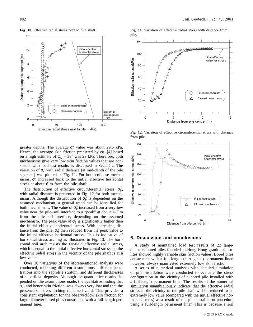
greater depths. The average σr′ value was about 29.5 kPa.Hence, the average skin friction predicted by eq. [4] basedon a high estimate of φcv = 38° was 23 kPa. Therefore, bothmechanisms give very low skin friction values that are con-sistent with load test results as discussed in Sect. 4.2. Thevariation of σr′ with radial distance (at mid-depth of the pilesegment) was plotted in Fig. 11. For both collapse mecha-nisms, σr′ increased back to the initial effective horizontalstress at about 6 m from the pile shaft.
The distribution of effective circumferential stress, σθ′,with radial distance is presented in Fig. 12 for both mecha-nisms. Although the distribution of σθ′ is dependent on theassumed mechanism, a general trend can be identified forboth mechanisms. The value of σθ′ increased from a very lowvalue near the pile–soil interface to a “peak” at about 1–3 mfrom the pile–soil interface, depending on the assumedmechanism. The peak value of σθ′ is significantly higher thanthe initial effective horizontal stress. With increasing dis-tance from the pile, σθ′ then reduced from the peak value tothe initial effective horizontal stress. This is indicative ofhorizontal stress arching as illustrated in Fig. 13. The hori-zontal soil arch resists the far-field effective radial stress,which is equal to the initial effective horizontal stress, so theeffective radial stress in the vicinity of the pile shaft is at alow value.
Over 20 variations of the aforementioned analysis wereconducted, reflecting different assumptions, different pene-trations into the saprolite stratum, and different thicknessesof superficial deposits. Although the quantitative results de-pended on the assumptions made, the qualitative finding thatσr′, and hence skin friction, was always very low and that thepresence of stress arching remained valid. This provides aconsistent explanation for the observed low skin friction forlarge-diameter bored piles constructed with a full-length per-manent liner.
6. Discussion and conclusions
A study of maintained load test results of 22 large-diameter bored piles founded in Hong Kong granitic sapro-lites showed highly variable skin friction values. Bored pilesconstructed with a full-length (corrugated) permanent liner,however, always manifested extremely low skin friction.
A series of numerical analyses with detailed simulationof pile installation were conducted to evaluate the stressconfiguration in the vicinity of a bored pile installed witha full-length permanent liner. The results of the numericalsimulation unambiguously indicate that the effective radialstress in the vicinity of the pile shaft will be reduced to anextremely low value (compared with the initial effective hor-izontal stress) as a result of the pile installation procedureusing a full-length permanent liner. This is because a soil
© 2003 NRC Canada
802 Can. Geotech. J. Vol. 40, 2003
Fig. 10. Effective radial stress next to pile shaft. Fig. 11. Variation of effective radial stress with distance frompile.
Fig. 12. Variation of effective circumferential stress with distancefrom pile.
I:\cgj\CGJ40-04\T03-028.vpJuly 30, 2003 2:51:19 PM
Color profile: Generic CMYK printer profileComposite Default screen

arch was formed to resist the far-field effective radial stress,which is equal to the initial effective horizontal stress, thusleading to low effective radial stress in the vicinity of thepile shaft.
The extremely low effective radial stress in the vicinity ofthe pile shaft will give very low skin friction values, even ifa high pile–soil interface friction angle was assumed.
This implies that large-diameter bored piles relying onside friction should not be installed with a full-length perma-nent liner in saprolites unless special techniques to reintro-duce the effective radial stress along the pile–soil interfaceare implemented.
Acknowledgements
The work described in this paper was partly supported bya grant from the Research Grants Council of the Hong KongSpecial Administrative Region, China (Project HKU 7006/01E). Part of the data analysis reported in this paper wasconducted while the first author was on special studies leaveat the Hong Kong University of Science and Technology.The assistance from many friends in industry are gratefullyacknowledged.
References
Au, S.W.C. 1990. Some observations on horizontal drain flow andpiezometric response. In Proceedings of the 6th International Con-gress of the Association of Engineering Geology, Amsterdam, 6–10 Aug. 1990. Vol. 2. Edited by D.G. Price. A.A. Balkema, Rotter-dam, The Netherlands. pp. 1149–1156.
Au, S.W.C. 1998. Rain induced slope instability in Hong Kong.International Journal of Engineering Geology, 5: 1–36.
Au, S.W.C., and Lo, S.-C.R. 1993. Use of waterhead support in theconstruction of large diameter bored piles: potential savingsand problems. In Proceedings of the 11th Southeast AsianGeotechnical Conference, Singapore, 5–9 Sept. 1993. pp. 489–494.
Chang, M.F., and Broms, B.B. 1991. Design of bored pilesin residual soils based on field-performance data. CanadianGeotechnical Journal, 28(2): 200–209.
Chang, M.F., and Wong, J.H. 1995. Axial load test behaviour ofbored piles in weathered granite. In Proceedings of the 10thAsian Regional Conference in Soil Mechanics and FoundationEngineering, Beijing. Vol. 1. pp. 185–188.
Fraser, R.A. 1985. Design of bored piles. Hong Kong Engineer,January 1985, pp. 37–48.
Fraser, R.A., and Kwok, D. 1986. Mobilization of skin friction inbored piles in Hong Kong. In Proceedings of the InternationalConference on Deep Foundations, Beijing. Vol. 2. pp. 2.65–2.74.
GEO. 1993. Guide to retaining wall design. Geotechnical Engi-neering Office, Hong Kong Government, Hong Kong.
GEO. 1996. Pile design and construction. GEO Publication 1/96,Geotechnical Engineering Office, Hong Kong Government,Hong Kong.
Holt, D.N., Lumb, P., and Wong, P.K.K. 1982. Site control andtesting of bored piles at Telford Gardens, an elevated townshipat Kowloon Bay, Hong Kong. In Proceedings of the 7th South-east Asian Geotechnical Conference, Hong Kong, Nov. 1982.pp. 349–361.
Hong Kong Government. 1995. Pile foundations. Practice Note forAuthorized Person and Registered Structural Engineer PNAP-141, Buildings Department, Hong Kong Government, Hong Kong.
Irfan, T.Y. 1996. Mineralogy fabric and classification of weatheredgranites in Hong Kong. Quarterly Journal of Engineering Geol-ogy, 29: 5–35.
Itasca Consulting Group Inc. 1998. Fast Lagrangian analysis ofcontinua (FLAC), version 3.4, user guide. Itasca ConsultingGroup Inc., Minneapolis, Minn.
Kay, J.N., and Kalinowski, M. 1997. Shaft friction for cast-in placepiles in Hong Kong. In Proceedings of the International Sympo-sium on Structures and Foundations in Civil Engineering, HongKong, 7–10 Jan. 1997. Hong Kong University of Science andTechnology, Hong Kong. pp. 1–6.
Kwok, D. 1987. Construction of large diameter bored pilesfounded on soil. M.Sc. thesis, The University of Hong Kong,Hong Kong.
Leroueil, S., and Vaughan, P.R. 1990. The general and congruenteffects of structures in natural soils and weak rocks.Géotechnique, 40(3): 467–488.
Lo, S-C.R., and Li, K.S. 1999. Challenges in the design and con-struction of large diameter bored piles founded in decomposedgranite. In Proceedings of the Conference on Construction Chal-lenges into the Next Century. 2–3 Dec. 1999, University ofHong Kong, Hong Kong. pp. 84–91.
Lo, S-C.R., and Li, K.S. 2000. Large diameter bored piles foundedin Hong Kong decomposed granite. In Proceedings of the Inter-national Conference on Geotechnical and Geological Engi-neering, GeoEng2000, Melbourne, 19–24 Nov. 2000.
Lumb, P. 1962a. The properties of decomposed granite. Géo-technique, 12(3): 226–243.
Lumb, P. 1962b. General nature of soils of Hong Kong. In Pro-ceedings of the Symposium on Hong Kong Soils, Hong Kong,22 and 29 May 1962. pp. 19–32.
Lumb, P. 1965. The residual soils of Hong Kong. Géotechnique,15(2): 180–194.
Lumb, P. 1975. Slope failures in Hong Kong. Quarterly Journal ofEngineering Geology, 8: 31–65.
Lumb, P. 1983. Engineering properties of fresh and decomposedgranites from Hong Kong. Quarterly Journal of Engineering Ge-ology, 19: 81–94.
© 2003 NRC Canada
Lo and Li 803
Fig. 13. Horizontal stress arching.
I:\cgj\CGJ40-04\T03-028.vpJuly 30, 2003 2:51:19 PM
Color profile: Generic CMYK printer profileComposite Default screen

Malone, A.W., Ho, K.K.S., and Lam, T.S.K. 1992. Piling in tropi-cally weathered granite. In GEOTROPIKA’92, Proceedings ofthe International Conference in Geotechnical Engineering, 21–23 April 1992, Universiti Technologi Malaysia, Kuala Lumper,Malaysia.
Meyerhof, C.G. 1976. Bearing capacity and settlement of pilefoundations. Journal of the Geotechnical Engineering Division,ASCE, 102(3): 196–228.
Ng, C.W.W., Rigby, D.B., Li, J.H.M., Yau, T.L.Y., Lee, S.C., andCarlton, C. 2000. Shaft resistance of large diameter bored pilesconstructed under water in saprolites. In Proceedings of the 19thAnnual Seminar of the Geotechnical Division, Hong Kong Insti-tution of Engineers, Hong Kong, 12 May 2000. pp. 135–144.
Poulos, H.G., and Davies, E.H. 1980. Pile foundation analysis anddesign. Wiley and Sons, New York.
Reese, L.C., and O’Neill, M.W. 1988. Drilled shaft: constructionprocedures and design method. U.S. Department of Transporta-tion, Federal Highway Administration, FHWA PublicationFHWA-HI-88-042.
Reese, L.C., and Wright, S.J. 1977. Design shaft manual: construc-tion procedures and deign for axial loading. Vol. 1. U.S. Depart-ment of Transportation, Implementation Division, HDV-22,Implementation Package 77-21.
Ruxton, B.P., and Berry, L. 1957. Weathering of granite and asso-ciated erosion features in Hong Kong. Bulletin of the GeologicalSociety of America, 68: 1263–1291.
Silva, S.D., Cheung, C.T., Pratt, M., and Walsh, N. 1998. Instru-mented bored and barrette pile load test for western harbourcrossing. In Proceedings of the 17th Annual Seminar, Geo-technical Division, Hong Kong Institution of Engineers, HongKong, 29 May 1998. pp. 77–94.
Tan, Y.C., Chen, C.S., and Liew, S.S. 1998. Load transfer behav-iour of cast-in place bored piles in tropical soils of Malaysia. InProceedings of the 13th Southeast Asian Geotechnical Confer-ence, 16–20 Nov. 1998, Taipei, Taiwan. pp. 563–571.
Touma, F.T., and Reese, L.C. 1974. Behaviour of bored piles insand. Journal of the Geotechnical Engineering Division, ASCE,100(7): 749–761.
Appendix A: Analysis of load test data
Maintained load tests were conducted on a number of full-scale large-diameter bored piles in Hong Kong. The maxi-mum test load is generally 1.5 to 2 times the allowable(working) load. Key test data for test piles instrumented withstrain gauges for measurement of skin friction are summa-rized in Table 1. In tests where skin friction was not fullymobilized at the maximum test load, an extrapolated valuebased on a displacement of 1% of the pile diameter was as-signed. Table 2 summarizes other load test results whereskin friction was not directly measured with strain gauges,but some inferences could be made from the load–settlementresponses based on Poulos and Davis (1980). The test datain Tables 1 and 2 are from GEO (1996), publications in thepublic domain, and the author’s knowledge and (or) involve-ment with projects. The construction method is describedin two columns in the tables, Excavation method andConcreting details. Additional descriptors for the excavationmethod (such as HG+ and HG#) are used when appropriate.
In view of the large variability as evident from Table 3,the possibility of correlation between N and the τ f /N ratiowas examined. No clear correlation can be identified.
Furthermore, one cannot make any general statement onwhether HG or RCD will give higher skin friction.
The load test results were compared with common designcorrelations for bored piles in sandy soil. Meyerhof (1976)suggested that a conservative estimation of skin friction forbored piles is given by the following:
[A1] τf /N = 1
The τ f /N ratio of unity is close to the mean value as listedin Table 3B for granitic saprolite, but the mean value in Ta-ble 3B is very different from a conservative estimate becauseof the very high variability (coefficient of variation COV =48%).
It is recognised that the data presented by Meyerhof(1976) are mainly for N ≤ 60, whereas the N values forsaprolite are, in general, considerably higher. Therefore asecond comparison was made with the empirical design cor-relation as proposed by Reese and Wright (1977) for N inthe range of 53–100 and reproduced in kPa units as follows:
[A2] τf = + −
160 10053
450N
This equation gives τ f /N of 2.7 at N = 60, and the ratioreduces to 1.2 at N = 150. Therefore eq. [A2], a design equa-tion that is supposedly conservative, also overestimates theτ f /N ratio by a significant extent.
Touma and Reese (1974) recommended a β value in therange of 0.5–0.7, which is significantly higher than the meanvalue in Table 3B.
Reese and O’Neill (1988) suggested that β should be cor-related to pile penetration but has a lower bound value of0.25. This lower bound value is close to the mean β value aslisted in Table 3B. In view of the large variability in β(COV = 53%), however, it cannot be considered as a conser-vative design value.
Although the aforementioned design correlations do notgive conservative predictions relative to the measured values,most of the test piles achieved high friction capacity (pro-vided piles constructed with full-length permanent linerswere excluded). This is because of (i) the high N values ingranitic saprolite and the depth where the saprolite stratumwas located, therefore giving high τ f even if the τ f /N ratio orβ are significantly lower than those given by common designcorrelations; and (ii) the large pile diameter and the long pilepenetration of the test pile.
It is pertinent to note that the skin friction values were ob-tained from large-scale and expensive test piles to verifydesign and (or) construction procedure(s). It is difficult tojustify discounting test results with τ f (or τ f /N or β) valuesless than the average values. Lo and Li (1999, 2000) pointedout that the influence of pile installation cannot be catego-rized by simple descriptors such as bore pile, underwater ex-cavation, HG, or RCD. Other factors such as “details” in thesinking of excavation casing, rate of concreting relative topile diameter and setting time of concrete may also have asignificant influence. This means that design based on themean values as listed in Table 3B needs to be verified by aproject-specific load test, which is in line with current prac-tice, unless a very prescriptive construction specification isagreed upon by the piling community of Hong Kong.
© 2003 NRC Canada
804 Can. Geotech. J. Vol. 40, 2003
I:\cgj\CGJ40-04\T03-028.vpJuly 30, 2003 2:51:20 PM
Color profile: Generic CMYK printer profileComposite Default screen

Appendix B: Modelling of collapse into theannulus void
The analysis is a multistage incremental large deformationanalysis using a finite difference stress analysis programFLAC (Itasca Consulting Group Inc. 1998).
The genesis of the fill-in mechanism is simulated by fivesets of user-defined procedures for five analysis stages.These five analysis stages, I–V, are explained below.(I) Installation of casing was modelled by provision of
horizontal support (fixity). To model the effect of dis-turbance due to casing installation, the friction anglewas reduced to φcv and stiffness parameters were re-duced to 60% of the in situ value in a near-field zoneof 0.5 times the pile diameter.
(II) Forming of the concrete piles was modelled by turningappropriate elements into elastic elements. The adjoin-ing column of elements was also turned into null ele-ments (to represent the gap). The interface elementswere also activated along the periphery of the concretepile.
(III) Withdrawal of casing was modelled by progressivelyremoving the lateral support assigned in stage I. Thecohesion of the soil, however, was maintained at the insitu value to maintain transient stability of the unsup-ported soil surface.
(IV) Collapse of soil into the gap was modelled by progres-sively turning the null elements (representing the gapin stage II) into soil elements with properties of aloose, decomposed granite fill. Soil that collapsed inabove the 12 m segment was represented by the appli-cation of an equivalent pressure.
(V) The soil cohesion was reduced to zero in the near-fieldzone and an intermediate value (between 0 and 20 kPa)
over a transition zone of one times the pile diameter.This reduction was achieved in 20 increments.
Maintaining c = 20 kPa in the near-field zone during cas-ing withdrawal (stages III and IV) is tenable, as the saprolitemay not be likely to achieve a fully drained response duringthe short period needed to withdraw the casing. The sa-prolite, being dilatant, will give a transient negative pore-water change, which in turn will give a higher transientshear strength. The dimension of the gap allows the overly-ing (and weaker) soil to collapse into the gap. At stage V,which models the eventual occurrence of a drained response,the surrounding soil imparts additional radial stress.
In modelling the close-in mechanism, only three analysisstages were needed. Stages I and II were the same as thoseof the fill-in mechanism. Stage III, however, was defined bya different set of procedures. It had two substages, IIIa andIIIb.(IIIa) The cohesion soil in the vicinity of the pile was as-
signed the drained soil parameters of zero in the near-field zone and increasing back to the in situ value inthe transition zone prior to casing withdrawal.
(IIIb) Withdrawal of casing was modelled by removing thelateral supports (installed in stage I) progressively on anode-by-node basis, and with the system of equationssolved for the removal of each support.
As a result of stage IIIa, the pile excavation will not beself-supporting because of the lack of cohesion. Hence thesurrounding soil will “close in” during the progressive re-moval of support. Closing-in of the soil on the pile surface,and the subsequent generation of radial stress, was trackedby the interface elements activated in stage II.
© 2003 NRC Canada
Lo and Li 805
I:\cgj\CGJ40-04\T03-028.vpJuly 30, 2003 2:51:20 PM
Color profile: Generic CMYK printer profileComposite Default screen