Embed Size (px)
Citation preview
CARLO GAVAZZIA u t o m a t i o n C o m p o n e n t s
IndustrialRelaysand Sockets
Overview
IndustrialRelaysand Sockets
2
Introduction 6
Industrial relays RCP 12
Sockets for RCP relays 16
Midi industrial relays RMI 26
Sockets for RMI relays 41
Power relays N series 68
Midi industrial relays RPY 47
Sockets for RPY relays 63
Power relays CS30/CF30 73
Sockets for miniaturterelays 75
Sockets for RLS relays 77
Modules, Springs andAccessories 79

2 Specifications are subject to change without notice. Pictures are just an example. For special features and/or customization, please ask to our sales network. 011010
Industrial RelaysOverview
Dimensions H x W x D mmH x W x D inches
Terminal typesNo. of Contacts
Contact ratingFeatures standard with:
Output SpecificationsMax. load AC1Min. loadElectrical life
Switching power
General SpecificationsVoltage ranges VDC
Voltage ranges VAC
Insulation Coil/ContactConsumptionApprovals/Conformity
ReferencesOn page
Dimensions H x W x D mmH x W x D inches
Terminal typesNo. of Contacts
Contact ratingFeatures standard with:
Output SpecificationsMax. load AC1Min. loadElectrical life
Switching power
General SpecificationsVoltage ranges VDC
Voltage ranges VAC
Insulation according toConsumptionApprovals/Conformity
ReferencesOn page
Types
Types
56 x 35.5 x 35.52.20” x 1.40” x 1.40”
Plug-in2 Change-over (octal)
3 change-over (undecal) 10A
Test button/Flag/LED
10A / 250VAC5mA / 12VDC
> 100.000 cycles
2500VA (resistive)
6 - 12 - 24 - 48 - 60100 - 110
6 - 12 - 24 - 48115/120 - 230EN 61810-5
1.5W DC-2.5 VA ACCE,TÜV,UR,CSA,IMQ,RINA
12
36 x 21.5 x 281.42” x 0.85” x 1.10”
Plug-in - PCB2 Change-over
10ATest button/Flag/LED
10A / 250VAC10mA / 12VDC
> 100.000 cycles
2500VA (resistive)
6 - 9 - 12 - 24 - 36 - 48100 - 110 - 220 - 2406 - 12 - 24 - 36 - 48
110 - 120 - 220 - 240 - 380EN 61810-5
0.9W DC-1.2 VA ACCE,TÜV,UR,CSA,IMQ,RINA
26
36 x 21.5 x 281.42” x 0.85” x 1.10”
Plug-in - PCB3 Change-over
7ATest button/Flag/LED
7A / 250VAC10mA / 12VDC
> 100.000 cycles
1750VA (resistive)
6 - 9 - 12 - 24 - 36 - 48100 - 110 - 220 - 2406 - 12 - 24 - 36 - 48120 - 220 - 240 - 380
EN 61810-50.9W DC-1.2 VA ACCE,TÜV,UR,CSA,IMQ
29
36 x 21.5 x 281.42” x 0.85” x 1.10”
Plug-in - PCB4 Change-over
5ATest button/Flag/LED
5A / 250VAC10mA / 12VDC
> 100.000 cycles
1250VA (resistive)
6 - 9 - 12 - 24 - 36 - 48100 - 110 - 220 - 2406 - 12 - 24 - 36 - 48120 - 220 - 240 - 380
EN 61810-50.9W DC-1.2 VA AC
CE,TÜV,UR,CSA,IMQ,RINA
32
RMI 2-10 (2 Poles)High Inrush
RMI 3-7 (3 Poles)High Inrush
RMI 4-5 (4 Poles)High Inrush
RCP8 / RCP11
36 x 21.5 x 281.42” x 0.85” x 1.10”
Plug-in - PCB2 Change-over
10ATest button/Flag/LED
12A / 250VAC5mA / 12VDC
> 100.000 cycles
2500VA (resistive)
5 - 6 - 12 - 24 - 4860 - 110
6 - 12 - 24 - 48115/120 - 230EN 61810-5
0.9W DC-1.2 VA ACCE,TÜV,UR,CSA,IMQ
35
RMI 2-10 (2 Poles)
36 x 21.5 x 281.42” x 0.85” x 1.10”
Plug-in - PCB4 Change-over
5ATest button/Flag/LED
6A / 250VAC5mA / 12VDC
> 100.000 cycles
1250VA (resistive)
5 - 6 - 12 - 24 - 4860 - 110
6 - 12 - 24 - 48115/120 - 230EN 61810-5
0.9W DC-1.2 VA ACCE,TÜV,UR,CSA,IMQ
38
RMI 4-5 (4 Poles)

36 x 50.5 x 33.51.42” x 1.99” x 1.32”Faston - Bolt - PCB
1 Normally open2 Normally open
30ADIN rail mount./Test button/LED
30A (1NO) - 25A (2NO)-
1 x 10⁵
8370VA / 840W
6 - 12 - 24 - 48100 - 110
12 - 24 - 48 115 - 2304000VAC
DC=1.9W - AC=2.5VACE,TÜV,cURus
68
26.42 x 68.58 x 34.541.04” x 2.70” x 1.35”
Faston - PCB2 Normally open2 Change-over
30A-
30A-
1 x 10⁵
8310VA / 840W
6 - 12 - 24 - 48 - 110
24 - 120 - 220 - 240 - 277
4000 VACDC=1.7 W - AC=4 VA
CE,cURus
73
Specifications are subject to change without notice. Pictures are just an example. For special features and/or customization, please ask to our sales network. 011010 3
Industrial RelaysOverview
Dimensions H x W x D mmH x W x D inches
Terminal typesNo. of Contacts
Contact ratingFeatures standard with:
Output SpecificationsMax. load AC1Min. loadElectrical life
Switching power
General SpecificationsVoltage ranges VDC
Voltage ranges VAC
Insulation Coil/ContactConsumptionApprovals/Conformity
ReferencesOn page
Dimensions H x W x D mmH x W x D inches
Terminal typesNo. of Contacts
Contact ratingFeatures standard with:
Output SpecificationsMax. load AC1Min. loadElectrical life
Switching power
General SpecificationsVoltage ranges VDC
Voltage ranges VAC
Insulation Coil/ContactConsumptionApprovals/Conformity
ReferencesOn page
Types
Types RPY 2 RPY 3 RPY4RPY 1
N series(1/2 Poles)CF / CS
36 x 21.5 x 28 1.42” x 0.85” x 1.10”
Faston or PCB1 Change-over
16 A-
16 A-
1 x 10⁵
1HP @ 240VAC - 1/2HP @ 120VAC
6 - 9 - 12 - 24 - 36 - 48 100 - 110 - 220 - 240
6 - 12 - 24 - 36 - 48 - 110 120 - 220 - 240 - 380
2000/1200VACDC=0.9 W - AC=1.2 VA
CE,TÜV,UR,CSA
47
36 x 21.5 x 281.42” x 0.85” x 1.10”
Faston or PCB2 Change-over
10 A-
10 A-
1 x 10⁵
3/4HP @ 240VAC - 1/3HP @ 120VAC
6 - 9 - 12 - 24 - 36 - 48 100 - 110 - 220 - 240
6 - 12 - 24 - 36 - 48 - 110 120 - 220 - 240 - 380
2000/1200VACDC=0.9 W - AC=1.2 VA
CE,TÜV,UR,CSA
51
36 x 31.5 x 28 1.42” x 1.24” x 1.10”
Faston or PCB3 Change-over
10 A-
10 A-
1 x 10⁵
3/4HP @ 240VAC - 1/3HP @ 120VAC
6 - 9 - 12 - 24 - 36 - 48 110 - 220
6 - 12 - 24 - 36 - 48 - 110 120 - 220 - 240 - 380
2000/1200VACDC=1.4 W - AC=2 VA
CE,TÜV,UR,CSA
55
36 x 41.5 x 281.42” x 1.63” x 1.10”
Faston or PCB4 Change-over
10 A-
10 A-
1 x 10⁵
3/4HP @ 240VAC - 1/3HP @ 120VAC
6 - 9 - 12 - 24 - 36 - 48 110 - 220
6 - 12 - 24 - 36 - 48 - 100/110 120 - 220 - 240 - 380
2000/1200VACDC=1.5 W - AC=2.5 VA
CE,TÜV,UR,CSA
59

21.5 x 47.5 x 330.85” x 1.87” x 1.30”
300V / 10A> 3kV
Phenolic-ResinPanel mounting
IP 00CE, cURus, CSA, CSv
RCP8 - RCP1125
4 Specifications are subject to change without notice. Pictures are just an example. For special features and/or customization, please ask to our sales network. 011010
Industrial SocketsOverview
General SpecificationsDimensions H x W x D mm
H x W x D inchesRated volt. / Rated curr.Insulation voltageSocket materialMounting Protection degreeApprovals
ReferencesRelay typesOn page
27 x 61.4 x 381.06” x 2.41” x 1.49”
400VAC / 10A> 3kV
PA6 6+ GF (V0)DIN-rail
IP 20CE, cURus
RCP8 - RCP1122 / 23
26.2 x 61.4 x 381.03” x 2.41” x 1.49”
400VAC / 10A> 3kV
PA46-S250F6 (V0)DIN-rail
IP 20CE, cURus, IMQ, RINA
RCP8 - RCP1116 / 17
18.5 x Ø200.73” x Ø0.79”
300V / 10A> 3kVPPEmPCBIP 00
CE, cURus, CSA, CSv
RCP8 - RCP1124
General SpecificationsDimensions H x W x D mm
H x W x D inchesRated volt. / Rated curr.Insulation voltageSocket materialMounting Protection degreeApprovals
ReferencesRelay typesOn page
27 x 61.4 x 381.06” x 2.41” x 1.49”
300VAC / 10A> 3kV
PA66 + GF (V0)DIN-rail
IP 20CE, cURus
RCP8 - RCP1120 / 21
General SpecificationsDimensions H x W x D mm
H x W x D inchesRated volt. / Rated curr.Insulation voltageSocket materialMounting Protection degreeApprovals
ReferencesRelay typesOn page
Types
Types
Types
ZPD 8A / ZPD 11A ZPD 8XA / ZPD 11XA ZPD 9A / ZPD 12A
ZC 8 / ZC 11ZSN 8 / ZSN 11
29 x 67 x 29 1.14” x 2.63” x 1.14”
300VAC / 10A> 3kV
PA66 + GF (V0)DIN-rail
IP 20B (EN 60529)CE, cURus
RMI A2 - RMI A444
42.5 x 75 x 271.67” x 2.95” x 1.06”
300VAC / 10A> 4kV
PA66 + GF - V2DIN-rail
IP 20CE, cURus, IMQ, RINA
RMI A2 - RMI A441
29 x 69 x 24.51.14” x 2.72” x 0.96”
300VAC / 12A> 3kV
PA6 + GF - V2DIN-rail
IP 20B (EN 60529)CE
RMI A2 - RMI A443
62 x 77 x 272.44” x 3.03” x 1.06”
300VAC / 10A> 4kV
PA66 + GF - V2DIN-rail
IP 20CE, cURus
RMI A2 -RMI A3 - RMI A442
ZMI 2NA / ZMI 4NA ZMI 2 / 3 / 4SA
ZR 08
ZDM 14A
27 x 61.4 x 381.06” x 2.41” x 1.49”
300VAC / 10A> 3kV
PA6 + GF (V1)DIN-rail
IP 20CE, UR, CSA
RCP8 - RCP1118 / 19
ZPD 8 / ZPD 11
16 x 21.5 x 29 0.63” x 0.85” x 1.14”
300V / 12A - 300V / 10A2kVABSPCBIP 00
CE, cURus
RMI A2 - RMI A446
ZC 15/2A - ZC 15/4A
16.5 x 21.5 x 29.5 0.65” x 0.85” x 1.16”
250V / 10A2kV
PPEmPCBIP 00
CE, cURus, CSA, CSv
RMI A2 - RMI A446
ZC 15/2 - ZC 15/4
16 x 21.5 x 290.63” x 0.85” x 1.14”
300VAC / 16A2kVABSPCBIP 00CE
RPY A1 - RPY A267
ZY 08
16 x 41 x 290.63” x 1.61” x 1.14”
300VAC / 16A2kVABSPCBIP 00CE
RPY A467
ZY 14
General SpecificationsDimensions H x W x D mm
H x W x D inchesMaterialTerminal materialOperating temperatureProtection DegreeApprovals/Conformity
ReferencesSocket typesOn Page
Specifications are subject to change without notice. Pictures are just an example. For special features and/or customization, please ask to our sales network. 011010 5
Industrial SocketsOverview
General SpecificationsDimensions H x W x D mm
H x W x D inchesRated volt. / Rated curr.Insulation voltageSocket materialMounting Protection degreeApprovals
ReferencesRelay typesOn page
General SpecificationsDimensions H x W x D mm
H x W x D inchesRated volt. / Rated curr.Insulation voltageSocket materialMounting Protection degreeApprovals
ReferencesRelay typesOn Page
Types
Types
Types
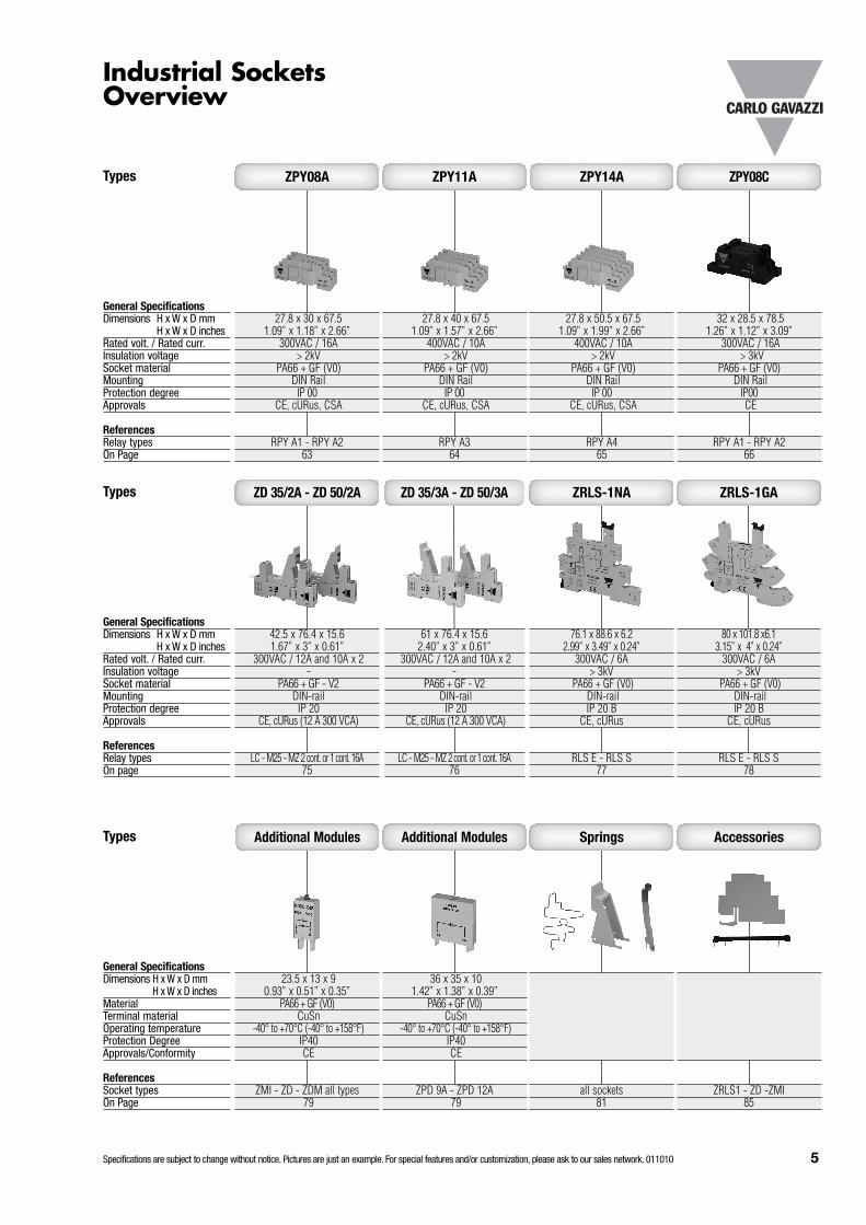
27.8 x 30 x 67.51.09” x 1.18” x 2.66”
300VAC / 16A> 2kV
PA66 + GF (V0)DIN Rail
IP 00CE, cURus, CSA
RPY A1 - RPY A263
ZPY08A
27.8 x 40 x 67.51.09” x 1.57” x 2.66”
400VAC / 10A> 2kV
PA66 + GF (V0)DIN Rail
IP 00CE, cURus, CSA
RPY A364
ZPY11A
27.8 x 50.5 x 67.51.09” x 1.99” x 2.66”
400VAC / 10A> 2kV
PA66 + GF (V0)DIN Rail
IP 00CE, cURus, CSA
RPY A465
ZPY14A
32 x 28.5 x 78.51.26” x 1.12” x 3.09”
300VAC / 16A> 3kV
PA66 + GF (V0)DIN Rail
IP00CE
RPY A1 - RPY A266
ZPY08C
42.5 x 76.4 x 15.61.67” x 3” x 0.61”
300VAC / 12A and 10A x 2-
PA66 + GF - V2DIN-rail
IP 20CE, cURus (12 A 300 VCA)
LC - M25 - MZ 2 cont. or 1 cont. 16A75
ZD 35/2A - ZD 50/2A
61 x 76.4 x 15.62.40” x 3” x 0.61”
300VAC / 12A and 10A x 2-
PA66 + GF - V2DIN-rail
IP 20CE, cURus (12 A 300 VCA)
LC - M25 - MZ 2 cont. or 1 cont. 16A76
ZD 35/3A - ZD 50/3A
76.1 x 88.6 x 6.22.99” x 3.49” x 0.24”
300VAC / 6A> 3kV
PA66 + GF (V0)DIN-railIP 20 B
CE, cURus
RLS E - RLS S77
ZRLS-1NA
80 x 101.8 x6.13.15” x 4” x 0.24”
300VAC / 6A> 3kV
PA66 + GF (V0)DIN-railIP 20 B
CE, cURus
RLS E - RLS S78
ZRLS-1GA
ZRLS1 - ZD -ZMI85
Accessories
all sockets81
Springs
36 x 35 x 101.42” x 1.38” x 0.39”
PA66 + GF (V0)CuSn
-40° to +70°C (-40° to +158°F)IP40CE
ZPD 9A - ZPD 12A79
Additional Modules
23.5 x 13 x 90.93” x 0.51” x 0.35”
PA66 + GF (V0)CuSn
-40° to +70°C (-40° to +158°F)IP40CE
ZMI - ZD - ZDM all types79
Additional Modules
6 Specifications are subject to change without notice. Pictures are just an example. For special features and/or customization, please ask to our sales network. 011010
General Information
IntroductionAccording to the U.S.A.S.I. (United Statesof America Standards Institute) a relaycan be defined as: an electricallycontrolled device that opens and closesan electrical contact to effect theoperation of other devices in the same oranother circuit. Relays are an importantfactor in today's industrial processes.
More than 25 billion relays operate todayall over the world as an interface betweenelectrical control circuits and electricalloads. Technical progress has lead tominiature-sized relays in mono-, bi- andtristable executions which need only a little or even no supply voltage toproduce high contact power.
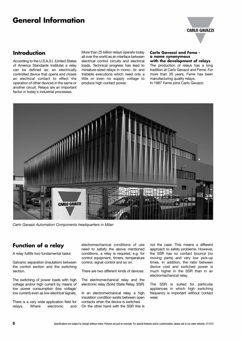
Carlo Gavazzi and Feme - a name synonymous with the development of relaysThe production of relays has a longtradition at Carlo Gavazzi and Feme. Formore than 35 years, Feme has beenmanufacturing quality relays. In 1987 Feme joins Carlo Gavazzi.
Function of a relayA relay fulfills two fundamental tasks:
Galvanic separation (insulation) betweenthe control section and the switchingsection.
The switching of power loads with highvoltage and/or high current by means oflow power consumption (low voltage/low current) even as low electrical signals.
There is a very wide application field forrelays. Where electronic and
electromechanical conditions of useneed to satisfy the above mentionedconditions, a relay is required, e.g. forcontrol equipment, timers, temperaturecontrol, signal control and so on.
There are two different kinds of devices:
The electromechanical relay and theelectronic relay (Solid State Relay, SSR)
In an electromechanical relay, a highinsulation condition exists between opencontacts when the device is switched. On the other hand with the SSR this is
not the case. This means a differentapproach to safety problems. However,the SSR has no contact bounce (nomoving parts) and very low pick-uptimes. In addition, the ratio betweendevice cost and switched power ismuch higher in the SSR than in anelectromechanical relay.
The SSR is suited for particularappliances in which high switchingfrequency is important without contactwear.
Carlo Gavazzi Automation Components headquarters in Milan

Specifications are subject to change without notice. Pictures are just an example. For special features and/or customization, please ask to our sales network. 011010 7
Main parts of a relay
An electromechanical relay composestwo different devices or parts:
an electromagnetic and an electricalswitch.
The first is the control section and thesecond the switching section used to bedirectly applied to the electrical load. Theelectromagnet makes a conversion of anelectrical current into a magnetic fluxwhich generates a force to move theswitching part.
Electromagnet
Fig. 1 shows a classic electromagnetconfiguration with the four basic parts:The coil: This consists of one or morecopper wire windings, usually wound overa bobbin made of an insulated material. The ferromagnetic core.The ferromagnetic joke. The ferromagnetic moving armature.Additional parts:- Contact springs: (Contact blades) fixed and movable
- Contacts - Push-bar - Contacts and coil pins - Contact support base - Dust cover
Switching section
The classic switching sectionconfiguration is formed by one changeover contact scheme. In the followingexplanation, this example will be usedsince it is the basic scheme to which allthe others may be referred to. The basic parts are:- the normally closed contact fixed
blade (NC)- the movable contact blade - the normally open contact fixed blade
(NO) - the push-bar - the insulation contact support base - the soldering contact pins
The code is the following: X, Y, Z
- X = number of NO contacts - Y = number of NC contacts - Z = number of change over contacts
For example, we can have the followingsituation: 100 = SPST-NO
(1-form A)010 = SPST-NC
(1-form B)001 = SPDT = 1d
(1-form C)200 = DPST-NO
(2-form A)020 = DPST-NC
(2-form B)002 = DPDT = 2d
(2-form C)and so on
Contact Materials
Contact materials and special alloyshave a great importance in switchingproblems and each appliance needs the correct evaluation of the electrical loadambient conditions and other informationto make to right choice.
Alloys and contact materials The choice of the contact materialdepends on the application. The mostcommonly used contact materials are:
SilverAg is probably the most widely usedcontact material available. It has thehighest electrical and thermalconductivity of any know metal andshows good resistance to oxidation andtarnishing except in the presence ofsulfur. Sulfur-containing atmospheres willproduce silver sulfide that increasescontact resistance. Silver sulfide,however, is quite soft and easilydisplaced with adequate contactpressure and wipe or slide. Shelf lifeprotection and low initial contactresistance will be provided by a pore-free(1 to 3mm) gold plate (Au). As a result ofsilver’s high electrical and thermalconducivity, contacts of fine silver workwell at currents in the light to mediumrange (1-20A) where light to moderatecontact pressure is available and low
Main schemes andmechanical solutions
There are different contact schemeconfigurations to solve the various needsof the appliance problems: Normally opencontacts (NO), normally closed contacts(NC) and change over contacts are thebasic configurations used to draw all relaycontact configuration schemes. By usingthese basic contacts, we can constructmany relay configurations to succeed insolving the problems of appliances. Theonly theoretical limits are relaydimensions, electromagnetic power,switching power and drawingcomplications. The contact switchingcombinations available on a relay aredefined in terms of number of poles,number of throws (single or double),normal position (open or closed contacts),and the se quence to make and break.Abbrevia tions used to define the exactnature of the contacts are as follows:SP = single pole ST = single throw NO = normally open NC = normally closed B = break M = make DP = double pole DT = double throw and so on
Another classification is also used bysome relay producers (e.g. Feme).
Fig. 1 Classical relay structure
Dust cover Coil
Pins
8 Specifications are subject to change without notice. Pictures are just an example. For special features and/or customization, please ask to our sales network. 011010
The end of the electrical life occurs whenthe contacts are not able to switch theelectrical load within contact resistancevalues (or contact voltage drops) that,becoming higher, stops the regularswitching operations (the limits dependon application).
In relay specifications, electrical life isgiven in the following way: Number ofcycles at nominal current - nominalvoltage - stated frequency and ambienttemperature.
E.g. for relay type MZP 002 46 05, theelectrical life is: Number of cycles: 2 x 10⁵ at 5 A -250VAC - 50Hz resistive load 1000cycles /hour - ambient temperature 70°C.
In practice, customers also require the
Voltage 50 Hz sine
IV
III
I Time
II
Electrical relay life
The electrical life, or switching life, is theminimum number of cycles that a relay isable to perform under particularconditions of current, voltage, operatingfrequency and ambient temperature,where “cycle” is a complete switchingoperation, starting from OFF status toON status and back again to OFF status.
0 1 2 3 4 5 6 7 8 9 10 11 12
10
0.1
0.5
5
0.05
0.01
1
00 1 2 3 4 5 6 7 8 9 10 11 12
10
0.1
0.5
5
00.5
00.1
1
0
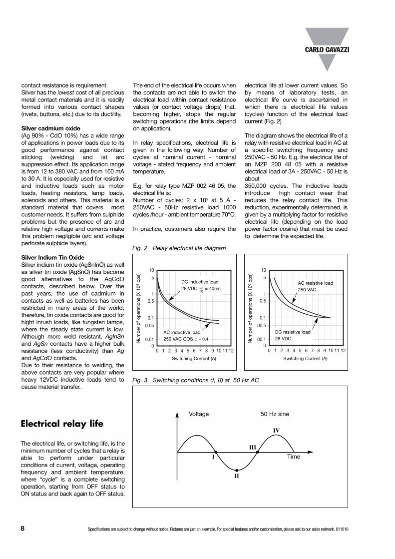
Fig. 2 Relay electrical life diagram
Fig. 3 Switching conditions (I, II) at 50 Hz AC
AC inductive load 250 VAC COS ϕ = 0,4
DC inductive load 28 VDC — = 40ms
L
R
AC resistive load 250 VAC
DC resistive load 28 VDC
Switching Current (A) Switching Current (A)
Num
ber
of
oper
atio
ns (X
106
ops)
Num
ber
of
oper
atio
ns (X
106
ops)
contact resistance is requirement.Silver has the lowest cost of all preciousmetal contact materials and it is readilyformed into various contact shapes(rivets, buttons, etc.) due to its ductility.
Silver cadmium oxide (Ag 90% - CdO 10%) has a wide rangeof applications in power loads due to itsgood performance against contactsticking (welding) and ist arcsuppression effect. Its application rangeis from 12 to 380 VAC and from 100 mAto 30 A. It is especially used for resistiveand inductive loads such as motorloads, heating resistors, lamp loads,solenoids and oth ers. This material is astandard material that covers mostcustomer needs. It suffers from sulphideproblems but the presence of arc andrelative high voltage and currents makethis problem negligible (arc and voltageperforate sulphide layers).
Silver Indium Tin OxideSilver indium tin oxide (AgSnInO) as wellas silver tin oxide (AgSnO) has becomegood alternatives to the AgCdOcontacts, described below. Over thepast years, the use of cadmium incontacts as well as batteries has beenrestricted in many areas of the world;therefore, tin oxide contacts are good forhight inrush loads, like tungsten lamps,where the steady state current is low.Although more weld resistant, AgInSnand AgSn contacts have a higher bulkresistance (less conductivity) than Agand AgCdO contacts.Due to their resistance to welding, theabove contacts are very popular whereheavy 12VDC inductive loads tend tocause material transfer.
electrical life at lower current values. Soby means of laboratory tests, anelectrical life curve is ascertained inwhich there is electrical life values(cycles) function of the electrical loadcurrent (Fig. 2)
The diagram shows the electrical life of arelay with resistive electrical load in AC ata specific switching frequency and250VAC - 50 Hz. E.g. the electrical life ofan MZP 200 48 05 with a resistiveelectrical load of 3A - 250VAC - 50 Hz isabout 350,000 cycles. The inductive loadsintroduce high contact wear thatreduces the relay contact life. Thisreduction, ex perimentally determined, isgiven by a multiplying factor for resistiveelectrical life (depending on the loadpower factor cosine) that must be usedto determine the expected life.

Specifications are subject to change without notice. Pictures are just an example. For special features and/or customization, please ask to our sales network. 011010 9
0 5 10 50 100 500 1000
0.1
0.5
1
10
5
0
AC Resistive load
DC Resistive load
0 5 10 50 100 500 1000
0.1
0.5
1
10
5
0
Fig. 5 Max. switching power in DC / ACFig. 4 R-C is a suppressor circuit
Inductiveload
Inductiveload
a)I
E R C
b)
RV / I C
AC inductiveload COS ϕ = 0.4
DC inductive load — = 40msL
R
DC inductive load — = 7msL
R
Rated Voltage (V)
Rat
ed C
urre
nt (A
)
Rated Voltage (V)
Rat
ed C
urre
nt (A
)
Switching in ACand DCDifferent problems are involved inswitching AC and DC electrical powerloads and different aspects must beconsidered to understand the matter. In AC circuits (about 50 - 60Hz frequency) when relay contacts open,they may do it on two possible voltageload conditions with regard to voltagesine and arc phenomena (see Fig. 3).Switching on point I: Voltage is near zero value: No arc occurs. Switching between I - II: We may have two situations in whichvoltage increases or decreases. In bothcases arcing occurs but, owing tovoltage crossing through the zero value,it is estinguished. As you know,electrical arcing depends on voltagevalue, con tact gap, current intensity andcontact shape and materials: For thesereasons, in miniature relays there arephysical limits connected to the aboveparame ters that reduce the maximumswitching AC voltage to about 380VAC.AC inductive loads are heavier thanresistive ones from the point of view ofcontact wear, because load inductanceincreases the arc permanence with itsdamaging effects.
Arc interruption
In DC appliances, the arc interruption is acritical problem, because voltage doesnot cross the zero value like in AC. Sowhen the electrical arc occurs, onlycontact gap and contact materialproperties contribute to arc extinction.Relays have normally a physical limit,depending on the above parameters, thatmake them unable to switch the load withcurrents and voltages higher than thespecific values. These values areexpressed by means of a curve that givesthe maximum switching power (U x I) withresistive and inductive loads L/R value ofthe timing constant is given L =inductance (Henry), R = resistance (Ohm).
Specific loads
Motor loadsMotor loads are inductive loads that showa particular behaviour when switched on.A current peak occurs due to the rotorinertia that is connected to themechanical load applied to it. A lockedrotor may have up to 6 times the ratedcurrent. Moreover, when it is switchedOFF, we also have the damaging effectcaused by inductive loads. So the rightcontact material choice is connected tothe above load characteristics especial-ly if a capacitor is connected to the motor.AgSnO2 and tungsten contact materialsare especially used for this application.Normally the motor load is expressed inHP (horse power), where 1HP is equal toabout 745Watts.
Example: MZP A 001 41 10 has a motorload rating of 3/4 HP.
Capacitive loadsThis is the heaviest contact load to beswitched ON due to the high inrushcurrent peak that occurs when thecapacitor is discharged (like a short-circuit). The peak intensity may reachhundreds of ampères for a short time(micro-millisec onds) that must besupported by contacts. The contactsticking problem may be avoided in twoways:- use of Tungsten contacts- reducing the current peak by introduc
ing a current limiting resistorThe same problem occurs when closingcontacts with a charged capacitor: Aviolent discharge results.
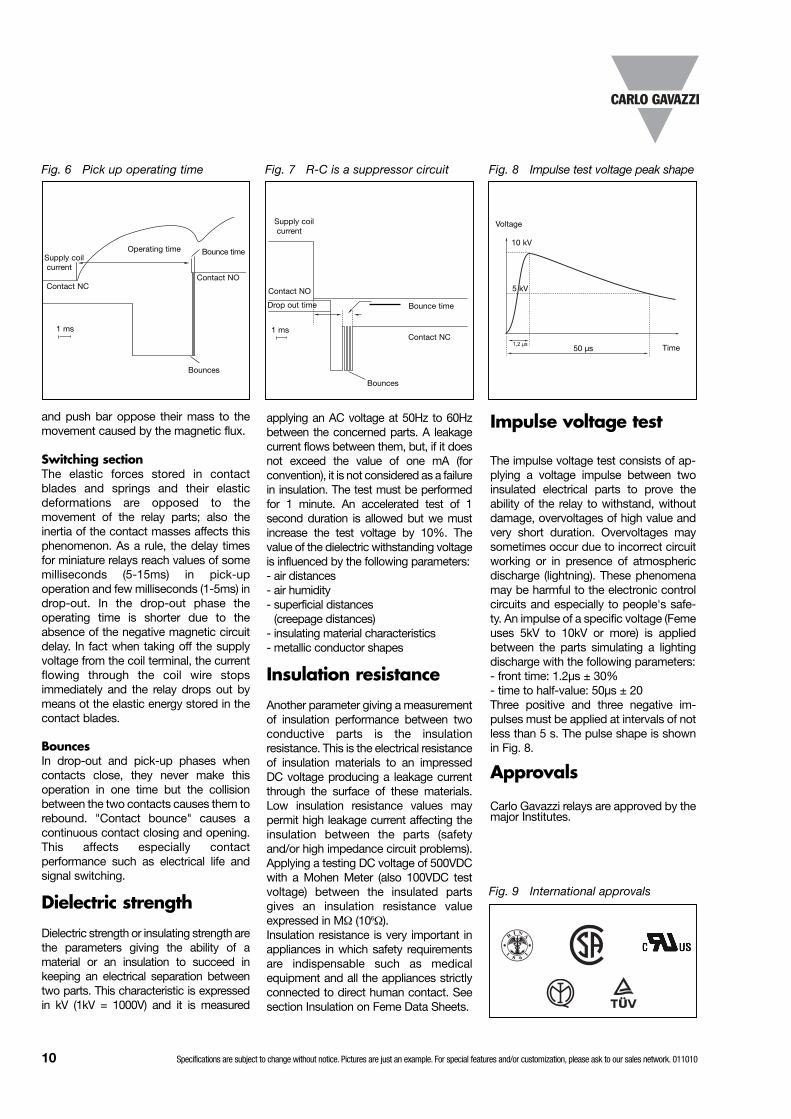
Switching time andcontact bounce
When supplying a relay coil for openingand/or closing, this operation will happenin a time depending on electrical andmechanical inertia of the parts. The delaywhich elapses between the coil supplyimpulse and the steady contact closureor/and opening is the sum of the influenceof the electromagnetic group and theswitching section.
Electromagnetic groupThe current flows through the coil with adelay caused by the coil inductance thatopposes itself to current flux. Moreover,the movable parts such as the armature
10 Specifications are subject to change without notice. Pictures are just an example. For special features and/or customization, please ask to our sales network. 011010
Fig. 6 Pick up operating time Fig. 8 Impulse test voltage peak shape
Fig. 9 International approvals
Fig. 7 R-C is a suppressor circuit
and push bar oppose their mass to themovement caused by the magnetic flux.
Switching sectionThe elastic forces stored in contactblades and springs and their elasticdeformations are opposed to themovement of the relay parts; also theinertia of the contact masses affects thisphenomenon. As a rule, the delay timesfor miniature relays reach values of somemilliseconds (5-15ms) in pick-upoperation and few milliseconds (1-5ms) indrop-out. In the drop-out phase theoperating time is shorter due to theabsence of the negative magnetic circuitdelay. In fact when taking off the supplyvoltage from the coil terminal, the currentflowing through the coil wire stopsimmediately and the relay drops out bymeans ot the elastic energy stored in thecontact blades.
BouncesIn drop-out and pick-up phases whencontacts close, they never make thisoperation in one time but the collisionbetween the two contacts causes them torebound. "Contact bounce" causes acontinuous contact closing and opening.This affects especially contactperformance such as electrical life andsignal switching.
Dielectric strength
Dielectric strength or insulating strength arethe parameters giving the ability of amaterial or an insulation to succeed inkeeping an electrical separation betweentwo parts. This characteristic is expressedin kV (1kV = 1000V) and it is measured
RI N A
1
8 6
1
Contact NO
Operating time
Bounces
Bounce time
Contact NC
1 ms
Supply coilcurrent
Supply coilcurrent
Bounces
1 msContact NC
Bounce timeDrop out time
Contact NO
Voltage
Time50 µs
5 kV
10 kV
1,2 µs
applying an AC voltage at 50Hz to 60Hzbetween the concerned parts. A leakagecurrent flows between them, but, if it doesnot exceed the value of one mA (forconvention), it is not considered as a failurein insulation. The test must be performedfor 1 minute. An accelerated test of 1second duration is allowed but we mustincrease the test voltage by 10%. Thevalue of the dielectric withstand ing voltageis influenced by the following parameters:- air distances- air humidity- superficial distances
(creepage distances)- insulating material characteristics- metallic conductor shapes
Insulation resistance
Another parameter giving a measurementof insulation performance between twoconductive parts is the insulationresistance. This is the electrical resistanceof insulation materials to an impressedDC voltage producing a leakage currentthrough the surface of these materials.Low insulation resistance val ues maypermit high leakage current affecting theinsulation between the parts (safetyand/or high impedance circuit problems).Applying a testing DC voltage of 500VDCwith a Mohen Meter (also 100VDC testvoltage) between the insulated partsgives an insulation resistance valueexpressed in MΩ (106Ω).Insulation resistance is very important inappliances in which safety requirementsare indispensable such as medicalequipment and all the appliances strictlyconnected to direct human contact. See section Insulation on Feme Data Sheets.
Impulse voltage test
The impulse voltage test consists of ap -plying a voltage impulse between twoinsulated electrical parts to prove theability of the relay to withstand, withoutdamage, overvoltages of high value andvery short duration. Overvoltages maysometimes occur due to incorrect circuitworking or in presence of atmosphericdischarge (lightning). These phenomenamay be harmful to the electronic controlcircuits and especially to people's safe-ty. An impulse of a specific voltage (Femeuses 5kV to 10kV or more) is appliedbetween the parts simulating a lightingdischarge with the following parameters:- front time: 1.2µs ± 30%- time to half-value: 50µs ± 20 Three positive and three negative im-pulses must be applied at intervals of notless than 5 s. The pulse shape is shownin Fig. 8.
Approvals
Carlo Gavazzi relays are approved by themajor Institutes.

Specifications are subject to change without notice. Pictures are just an example. For special features and/or customization, please ask to our sales network. 011010 11
DeclarationWe
CARLO GAVAZZI AUTOMATION S.p.A.Via Milano 13, 20020 - Lainate - MI - ITALY
Tel. +39 02 931761
with relevance to the European Directive 2002/95/EC of 27th January 2003 on the restriction of the use of certain hazardous substances
in electrical and electronic equipment (RoHS),
declare that all the products present in this catalogue, manufactured after December 2004,
are RoHS compliant as do not contain any of the following hazardous substances:
ASBESTOSMERCURY
LEADRADIOACTIVE LUMINOUS MATERIALS
HEXAVALENT CHROMIUMPBB
PBDEPBDF
Cadmium: Cadmium is present in the relays with AgCdO contacts. According to the Decision 2005/747/CE of the 21th October 2005, the Exempted
application list of the Directive 2002/95/CE has been modified including Cadmium and compounds in Electrical contacts. Although products with AgCdO
contacts are now RoHS compliant, versions without cadmium are available.

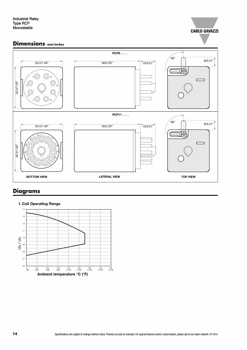
Coil operating range: see diagram n° 1 pag. 14
TypeNo. of pinsContact codeCoil codeOptions
Contact rating
10A
10A
Industrial Relay Type RCPMonostable
• 8 or 11-pin socket mounting• 2 or 3 change over contacts• Long life (minimum 100.000 electrical operations)
@ 10A 250VAC /30VDC resistive load• AC coils 6 to 230VAC• DC coils 6 to 110VDC• Matched sockets available• Standard with LED, Push arm and Flag• IP 40• Conform to CE low voltage directive• TÜV, UL, CSA, IMQ, RINA (marine) approved
RCP
Product Description Ordering Key RCP 8 002 24VDC /1
Contact code
002
003
Type Selection
The RCP relay can be usedfor a wide range of industrialapplications.
Available in 2 or 3 change-over contact configuration,Octal or Undecal version.
Coil Characteristics, DC Standard Coils 1.5W
Coil Characteristics, AC Standard Coils 2.7VA
Approvals
Contact configuration
2 change over contacts (DPDT {2-form C})
3 change over contacts (3PDT {3-form C})
Coil Code
Nominal voltage VDC
@ +20°C (+68°F) @ +40°C (+104°F)Coil
resistance ΩPick-up voltage VDC
Drop-out voltage VDC
Pick-up voltage VDC
Drop-out voltage VDC
6VDC 6 4.8 0.6 5.2 0.6 23.5 ±10%12VDC 12 9.6 1.2 10.3 1.3 95.0 ±10%24VDC 24 19.2 2.4 20.7 2.6 430.0 ±10%48VDC 48 38.4 4.8 41.4 5.1 1630.0 ±15%60VDC 60 48.0 6.0 48.6 6.4 1920.0 ±15%100VDC 100 80.0 10.0 86.4 10.8 6800.0 ±15%110VDC 110 88.0 11.0 95.0 11.8 7300.0 ±15%
CoilCode
Nominal Voltage VAC
@ +20°C (+68°F) @ +40°C (+104°F)Coil
resistance ΩPick-upvoltage VAC
Drop-outvoltage VAC
Pick-upvoltage VAC
Drop-outvoltage VAC
6VAC 6 4.8 1.8 5.2 1.9 3.9 ±10%
12VAC 12 9.6 3.6 10.3 3.8 16.3 ±10%
24VAC 24 19.2 7.2 20.7 7.7 70.0 ±10%
48VAC 48 38.4 14.4 41.4 15.5 315.0 ±15%
115/120VAC 115/120 88.0 36.0 95.0 38.8 1600.0 ±15%
230VAC 230 176.0 72.0 190.0 77.7 6800.0 ±15%
12 Specifications are subject to change without notice. Pictures are just an example. For special features and/or customization, please ask to our sales network. 011010
E60304
RI N A
1
8 6
1
Box content: 25 relaysBox size: (W 215 x D 205 x H 80) mm Weight: 2400g
(W 8.46 x D 8.07 x H 3.15) inches Weight: 84.65oz051377

Industrial Relay Type RCPMonostable
Contact CharacteristicsArrangement 002 / 003Contact rating(with resistive load) 10A - 250VAC / 30VDCUL rating 10A - 250VAC / 30VDC
1/3HP @ 240VAC1/3HP @ 120VAC1/2HP @ 277VAC
Standard rating 10A - 250VAC / 30VDCMax. rating 10A - 250VAC / 30VDCMaterial AgSnO2
CurrentMax. switching current 10AInitial contact resistance 100mΩ (@ 1A 24VDC)Max. switch. voltage 500VAC / 240VDCMax. switch. power resistive 2500VA / 300WMinimum CurrentMin. applicable load 5mA @ 12VDC/4 and /5 versions 1mA @ 6VDCLifeElectrical life 1x10⁵opsMechanical life 1x10⁷ops
InsulationTest Voltage (1 min.)Between coil and contacts 3750VAC Vr.m.sBetween open contacts 750VAC Vr.m.sContact/Contact 1250VA Vr.m.sInitial insulation resistance 500MΩ - 500VAC
Insulation according to EN61810-5Rated insulation voltage 250VImpulsive insulation voltage 3.6kVPollution degree 2Overvoltage category III
Industrial Relay Type RCPMonostable
Nil = Standard with Push Arm -LED (A1+) (A2-)- Flag
/0 = Diode against polarity inversion +free-wheeling Diode (A1+) (A2-)
/1 = Without LED/2 = Without Flag/3 = Without Push Arm/4 = Gilded Contacts Au 5µm
/5 = Gilded Contacts Au > 0.5µm/6 = Free-Wheeling Diode (A1+) (A2-)/7 = Free-Wheeling Diode (A1-) (A2+)
Options
/1Nil (standard) /6/0 /7
A2A1 -+ A2A1 A2A1 -+ A2A1 +-72 72 72 72 72
A2A1
General DataOperating time(At nominal voltage) 25ms max.Release time(At nominal voltage) 25ms max.Temperature rise(At nominal voltage) +70°C (+44.6°F)Ambient temperature -40° to +55°C (-40° to +131°F)Vibration resistance 10 to 55Hz 1.5mm (0.059”)
Shock resistanceFunctional 98m/s2 /10GDestructive 980m/s2 /100GHumidity 98%, +40°C% (+104°F%)Termination Octal/Undecal-type plug-inConstruction Dust coverWeight ~85g (~2.998oz)
BOTTOM VIEW RCP 11 ....
Wiring Diagrams
4 5
3
2
6
7
8
4
65 7
8
3 9
1021111 A2A1
A2A1
Specifications are subject to change without notice. Pictures are just an example. For special features and/or customization, please ask to our sales network. 011010 13
BOTTOM VIEW RCP 8 ....
-+
Diagrams
1 Coil Operating Range
UB
/ U
N
1.4
1.3
1.2
1.1
1.0
0.9
0.8
0.7
0.60 +10 +20 +30 +40 +50 +60 +70 +80(32) (+50) (+68) (+86) (+104) (+122) (+140) (+158) (+176)
RCP8 . . . .
RCP11 . . . .
13/0.51”
35.5
/1.4
0”
56/2.20”35.5/1.40”
13/0.51”
35.5
/1.4
0”
56/2.20”35.5/1.40”
3
2
4
8
6
7
5
2
1
3
4
6
7
9
10
11
5
8
Industrial Relay Type RCPMonostable
Industrial Relay Type RCPMonostable
8/0.31”
8/0.31”
90°
90°
BOTTOM VIEW LATERAL VIEW TOP VIEW
Dimensions mm/inches
Ambient temperature °C (°F)
14 Specifications are subject to change without notice. Pictures are just an example. For special features and/or customization, please ask to our sales network. 011010
1

Rated Voltage (V)
Rat
ed C
urre
nt (A
)
Rat
ed C
urre
nt (A
)
AC Resistive load
DC Resistive load
AC inductive load COS ϕ = 0.4
DC inductive load — = 40msL
R
DC inductive load — = 7msL
R
2 Electrical life
Num
ber
of
oper
atio
ns (X
106
ops)
Switching Current (A)
5
1
0.5
0.1
0.05
0.01
00 1 2 3 4 5 6 7 8 9 10 11 12 N
umb
er o
f op
erat
ions
(X 1
06op
s)
Switching Current (A)
AC inductive load 250VAC COS ϕ = 0.4
DC inductive load 28VDC — = 40ms
L
R
DC resistive load 28VDC
AC resistive load 250VAC
5
1
0.5
0.1
0.05
0.01
00 1 2 3 4 5 6 7 8 9 10 11 12
3 Max. Contact capacity
Rated Voltage (V)
10
5
1
0.5
0.1
00 5 10 50 100 500 1000
10
5
1
0.5
0.1
00 5 10 50 100 500 1000
Industrial Relay Type RCPMonostable
Industrial Relay Type RCPMonostable
Inductive loads Resistive loads
Specifications are subject to change without notice. Pictures are just an example. For special features and/or customization, please ask to our sales network. 011010 15
Bases and SocketsDIN rail sockets codes are ZPD8A, ZP11A, ZPD8, ZPD11, ZPD8XA, ZPD11XA, ZPD9A and ZPD12A details andspecifications from page 16 to 23 of industrial relays catalogue. PCB and Panel Soldering sockets codes are ZC8, ZC11 and ZSN8, ZSN11 details and specifications from page 24 to page25 of industrial relays catalogue.
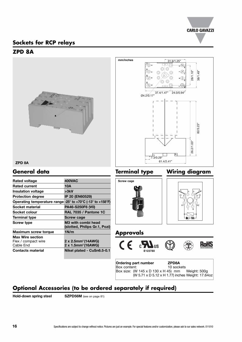
ZPD 8A
ZPD 8A
Rated voltage 400VACRated current 10AInsulation voltage >3kVProtection degree IP 20 (EN60529)Operating temperature range -25° to +70°C (-13° to +158°F)Socket material PA46-S250F6 (V0)Socket colour RAL 7035 / Pantone 1CTerminal type Screw cageScrew type M3 with combi head
(slotted, Philips Gr.1, Pozi)Maximum screw torque 1N/mMax Wire sectionFlex / compact wire 2 x 2.5mm2 (14AWG)Cable End 2 x 1.5mm2 (16AWG)Contacts material Nikel plated - CuSn6.5-0.1
2422
1214
65
43
78
12
A2
2111
A1
61.4/2.41”
Ø4.2/0.17”
28/1
.10”
38/1
.49”
26.2
/1.0
3”
Sockets for RCP relays
16 Specifications are subject to change without notice. Pictures are just an example. For special features and/or customization, please ask to our sales network. 011010
mm/inches
General data
Approvals
E123780
7.3/0.29”
82/3
.23”
31.9/1.25”
37.4/1.47” 24.0/0.94”
4 5
3
2
6
7
81
A2A1
Optional Accessories (to be ordered separately if required)Hold-down spring steel SZPD56M (see on page 81)
Ordering part number ZPD8ABox content: 10 socketsBox size: (W 145 x D 130 x H 45) mm Weight: 500g
(W 5.71 x D 5.12 x H 1.77) inches Weight: 17.64oz
Terminal type Wiring diagramScrew cage
RI N A
1
8 6
1

ZPD 11A
ZPD 11A
Rated voltage 400VACRated current 10AInsulation voltage >3kVProtection degree IP 20 (EN60529)Operating temperature range -25° to +70°C (-13° to +158°F)Socket material PA46-S250F6 (V0)Socket colour RAL 7035 / Pantone 1CTerminal type Screw cageScrew type M3 with combi head
(slotted, Philips Gr.1, Pozi)Maximum screw torque 1N/mMax Wire sectionFlex / compact wire 2 x 2.5mm2 (14AWG)Cable End 2 x 1.5mm2 (16AWG)Contacts material Nikel plated - CuSn6.5-0.1
General data
3432
1412
A2
3121
A1
61.4/2.41”
Ø4.2/0.17”
28/1
.10”
38/1
.49”
26.2
/1.0
3”
mm/inches
7.3/0.29”
82/3
.23”
31.9/1.25”
37.4/1.47” 24.0/0.94”
Approvals
5 7
4
2
8
10111
93
6
A2A1
Optional Accessories (to be ordered separately if required)Hold-down spring steel SZPD56M (see on page 81 )
Ordering part number ZPD11ABox content: 10 socketsBox size: (W 145 x D 130 x H 45) mm Weight: 550g
(W 5.71 x D 5.12 x H 1.77) inches Weight: 19.40oz
Terminal type Wiring diagram
Sockets for RCP relays
Screw cage
E123780
RI N A
1
8 6
1
2422
98
34
75
11
1011
62
1
Specifications are subject to change without notice. Pictures are just an example. For special features and/or customization, please ask to our sales network. 011010 17

Approvals
ZPD 8
ZPD 8
Rated voltage 300VACRated current 10ACSA rating 12A @ 300VACUL rating 10A @ 300VAC
12A @ 150VACInsulation voltage >3kVProtection degree IP 20 (EN60529)Operating temperature range -25° to +85°C (-13° to +185°F)Socket material PA6+GF (V1)Socket colour RAL 7035 / Pantone 1CTerminal type Screw cageScrew type M3 with combi head
(slotted, Philips Gr.1, Pozi)Maximum screw torque 0.8N/mMax Wire sectionFlex / compact wire 2 x 2.5mm2 (14AWG)Cable End 2 x 1.5mm2 (16AWG)Contacts material Nikel plated - CuZn33
General data
Optional Accessories (to be ordered separately if required)Hold-down spring steel SZPD56M (see on page 81)
Ordering part number 9399020001Box content: 10 socketsBox size: (W 70 x D 140 x H 85) mm Weight: 600g
(W 2.75 x D 5.51 x H 3.35) inches Weight: 21.16oz
Terminal type Wiring diagram
Sockets for RCP relays
Screw cage
E123780
4 5
3
2
6
7
81
A2A1
5.6/0.22”
Ø3.1/0.12”
3/0.
12”
A2
24
12
145
3
72
1121822
A1
1
6
4
61.4/2.41”
Ø4.2/0.17”
30/1
.18”
38/1
.49”
mm/inches
83/3
.26”
27/1
.06”
18 Specifications are subject to change without notice. Pictures are just an example. For special features and/or customization, please ask to our sales network. 011010
5.6/0.22”
Ø3.1/0.12”
3/0.
12”
34
32
2122
75
4
9
A1
21
31A
210143
24
12
11
11
8
6
61.4/2.41”
Ø4.2/0.17”
30/1
.18”
38/1
.49”
mm/inches
83/3
.26”
27/1
.06”
5 7
4
2
8
10111
93
6
A2A1
Approvals
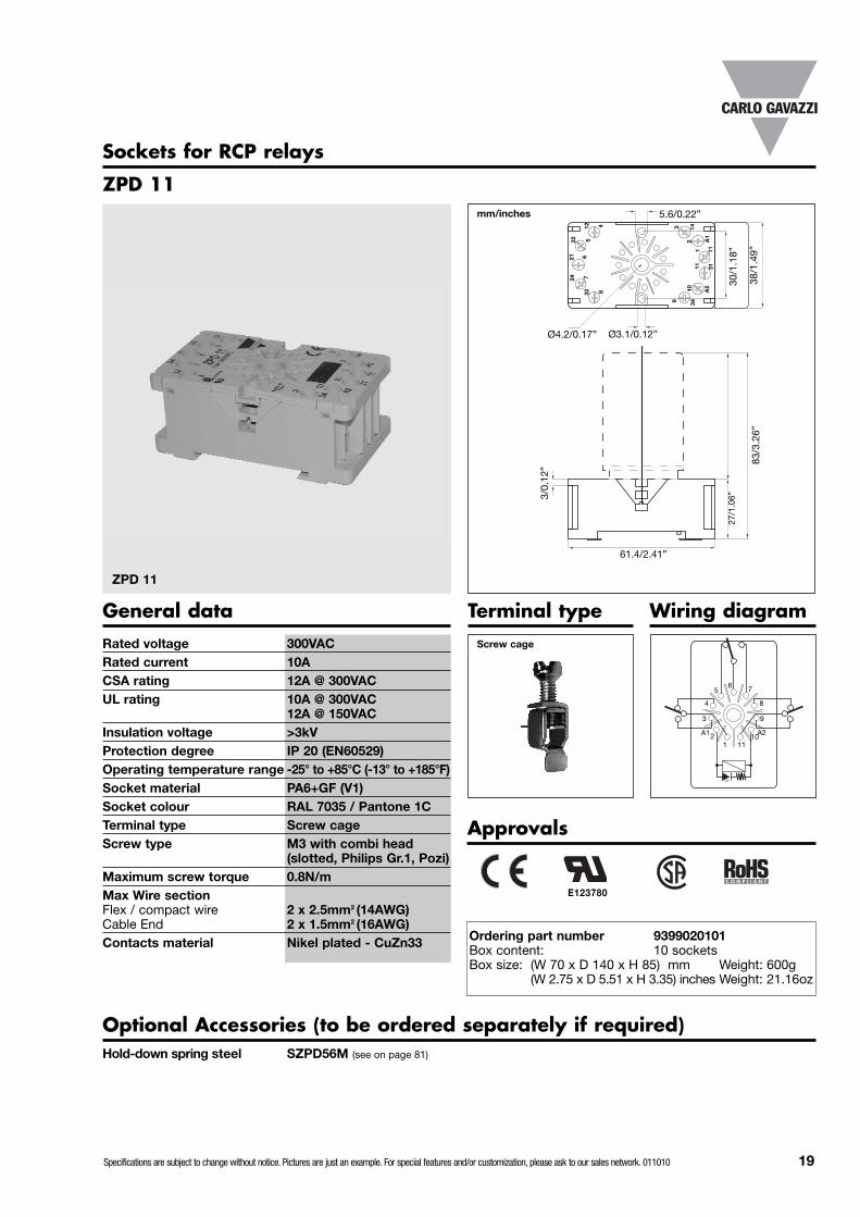
ZPD 11
ZPD 11
Rated voltage 300VACRated current 10ACSA rating 12A @ 300VACUL rating 10A @ 300VAC
12A @ 150VACInsulation voltage >3kVProtection degree IP 20 (EN60529)Operating temperature range -25° to +85°C (-13° to +185°F)Socket material PA6+GF (V1)Socket colour RAL 7035 / Pantone 1CTerminal type Screw cageScrew type M3 with combi head
(slotted, Philips Gr.1, Pozi)Maximum screw torque 0.8N/mMax Wire sectionFlex / compact wire 2 x 2.5mm2 (14AWG)Cable End 2 x 1.5mm2 (16AWG)Contacts material Nikel plated - CuZn33
General data
Optional Accessories (to be ordered separately if required)Hold-down spring steel SZPD56M (see on page 81)
Ordering part number 9399020101Box content: 10 socketsBox size: (W 70 x D 140 x H 85) mm Weight: 600g
(W 2.75 x D 5.51 x H 3.35) inches Weight: 21.16oz
Terminal type Wiring diagram
Sockets for RCP relays
Screw cage
E123780
Specifications are subject to change without notice. Pictures are just an example. For special features and/or customization, please ask to our sales network. 011010 19
5.6/0.22”
Ø3.1/0.12”
3/0.
12”
A2
24
12
145
3
72
1121822
A1
1
6
4
61.4/2.41”
Ø4.2/0.17”
30/1
.18”
38/1
.49”
mm/inches
83/3
.26”
27/1
.06”
Approvals
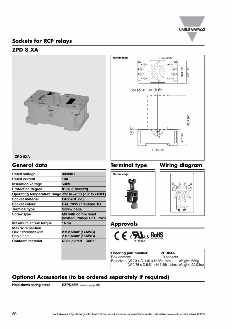
ZPD 8 XA
ZPD 8XA
Rated voltage 300VACRated current 10AInsulation voltage >3kVProtection degree IP 20 (EN60529)Operating temperature range -25° to +70°C (-13° to +158°F)Socket material PA66+GF (V0)Socket colour RAL 7035 / Pantone 1CTerminal type Screw cageScrew type M3 with combi head
(slotted, Philips Gr.1, Pozi)Maximum screw torque 1N/mMax Wire sectionFlex / compact wire 2 x 2.5mm2 (14AWG)Cable End 2 x 1.5mm2 (16AWG)Contacts material Nikel plated - CuSn
General data
Optional Accessories (to be ordered separately if required)Hold-down spring steel SZPD56M (see on page 81)
Ordering part number ZPD8XABox content: 10 socketsBox size: (W 70 x D 140 x H 85) mm Weight: 650g
(W 2.75 x D 5.51 x H 3.35) inches Weight: 22.93oz
Terminal type Wiring diagram
Sockets for RCP relays
Screw cage
4 5
3
2
6
7
81
A2A1
20 Specifications are subject to change without notice. Pictures are just an example. For special features and/or customization, please ask to our sales network. 011010
E123780
5.6/0.22”
Ø3.1/0.12”
3/0.
12”
34
32
2122
75
4
9
A1
21
31A
210143
24
12
11
11
8
6
61.4/2.41”
Ø4.2/0.17”
30/1
.18”
38/1
.49”
mm/inches
83/3
.26”
27/1
.06”
5 7
4
2
8
10111
93
6
A2A1
Approvals
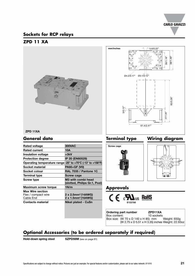
ZPD 11 XA
ZPD 11XA
Rated voltage 300VACRated current 10AInsulation voltage >3kVProtection degree IP 20 (EN60529)Operating temperature range -25° to +70°C (-13° to +158°F)Socket material PA66+GF (V0)Socket colour RAL 7035 / Pantone 1CTerminal type Screw cageScrew type M3 with combi head
(slotted, Philips Gr.1, Pozi)Maximum screw torque 1N/mMax Wire sectionFlex / compact wire 2 x 2.5mm2 (14AWG)Cable End 2 x 1.5mm2 (16AWG)Contacts material Nikel plated - CuSn
General data
Optional Accessories (to be ordered separately if required)Hold-down spring steel SZPD56M (see on page 81)
Ordering part number ZPD11XABox content: 10 socketsBox size: (W 70 x D 140 x H 85) mm Weight: 650g
(W 2.75 x D 5.51 x H 3.35) inches Weight: 22.93oz
Terminal type Wiring diagram
Sockets for RCP relays
Screw cage
Specifications are subject to change without notice. Pictures are just an example. For special features and/or customization, please ask to our sales network. 011010 21
E123780

Ø3.1/0.12”
7
2422
14
46
21
21
7
A1
3
11
8
5
12
61.4/2.41”
Ø4.2/0.17”
30/1
.18”
38/1
.49”
mm/inches
82/3
.23”
26/1
.02”
Approvals
ZPD 9A
ZPD 9A
Rated voltage 400VACRated current 10AInsulation voltage > 3kVProtection degree IP 20Operating temperature range -25° to +70°C (-13° to +158°F)Socket material PA66+GF (V0)Socket colour RAL 7035 / Pantone 1CTerminal type Screw cageScrew type M3 with combi head
(slotted, Philips Gr.1, Pozi)Maximum screw torque 1N/mMax Wire sectionFlex / compact wire 2 x 2.5mm2 (14AWG)Cable End 2 x 1.5mm2 (16AWG)Contacts material Nikel plated - CuZn33
General data
Optional Accessories (to be ordered separately if required)Hold-down spring steel SZPD56M (see on page 81)
Modules (see on page 79)
Ordering part number ZPD9ABox content: 10 socketsBox size: (W 152 x D 155 x H 50) mm Weight: 680g
(W 5.98 x D 6.10 x H 1.97) inches Weight: 23.98oz
Terminal type
Sockets for RCP relays
Screw cage
A2
A2
62/2
.44”
5 4
6
7
3
2
18
A1A2
Wiring diagram
22 Specifications are subject to change without notice. Pictures are just an example. For special features and/or customization, please ask to our sales network. 011010
Optional module
E123780

Approvals
ZPD 12A
ZPD 12A
Rated voltage 400VACRated current 10AInsulation voltage > 3kVProtection degree IP 20Operating temperature range -25° to +70°C (-13° to +158°F)Socket material PA66+GF (V0)Socket colour RAL 7035 / Pantone 1CTerminal type Screw cageScrew type M3 with combi head
(slotted, Philips Gr.1, Pozi)Maximum screw torque 1N/mMax Wire sectionFlex / compact wire 2 x 2.5mm2 (14AWG)Cable End 2 x 1.5mm2 (16AWG)Contacts material Nikel plated - CuZn33
General data
Optional Accessories (to be ordered separately if required)Hold-down spring steel SZPD56M (see on page 81)
Modules (see on page 79)
Ordering part number ZPD12ABox content: 10 socketsBox size: (W 152 x D 155 x H 50) mm Weight: 780g
(W 5.98 x D 6.10 x H 1.97) inches Weight: 27.51oz
Terminal type
Sockets for RCP relays
Screw cage
7 5
8
A2
4
2111
39
6
A110
Wiring diagram
Ø3.1/0.12”
10
2422
12
37
26
31
10
A1
4
21
11
5
1461.4/2.41”
Ø4.2/0.17”
30/1
.18”
38/1
.49”
mm/inches
82/3
.23”
26/1
.02”
A2
A2
62/2
.44”
3432
98
1 11
Specifications are subject to change without notice. Pictures are just an example. For special features and/or customization, please ask to our sales network. 011010 23
Optional module
E123780

24 Specifications are subject to change without notice. Pictures are just an example. For special features and/or customization, please ask to our sales network. 011010
mm/inches
Approvals
ZC 8 - ZC 11
ZC 8
Rated voltage 300VACRated current 10AInsulation voltage > 3kVProtection degree IP 00Operating temperature range -40° to +70°C (-40° to +150°F)Socket material PPEmSocket colour BlackTerminal type PCBContacts material Copper tin plated CuZn
General data
Ordering part number ZC8/20.5Ordering part number ZC11/22Box content: 100 socketsBox size: (W 13 x D 21 x H 12.5) mm ZC8 Weight: 880g
ZC11Weight: 1030g(W 0.51 x D 0.83 x H 0.49) inches ZC8 Weight: 31.04oz
ZC11Weight: 36.33oz
Sockets for RCP relays
E135170
ZC 11
28/1
.10”
28/1
.10”
69/2
.72”
69/2
.72”
18.5
/0.7
3”
18.5
/0.7
3”
13.5
/0.5
3”
13.5
/0.5
3”
Ø20/0.79” Ø22/0.87”
4 5
3
2
6
7
81
A2A1
Wiring diagram
5 7
4
2
8
10
111
93
6
A2A1
ZC8 ZC11
ZC 8 ZC 11
Specifications are subject to change without notice. Pictures are just an example. For special features and/or customization, please ask to our sales network. 011010 25
mm/inches
Approvals
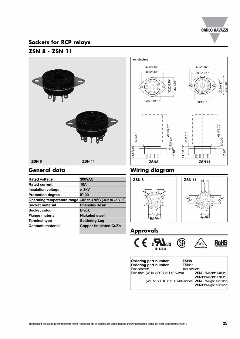
ZSN 8 - ZSN 11
ZSN 8
Rated voltage 300VACRated current 10AInsulation voltage > 3kVProtection degree IP 00Operating temperature range -40° to +70°C (-40° to +150°F)Socket material Phenolic-ResinSocket colour BlackFlange material Nickeled steelTerminal type Soldering LugContacts material Copper tin plated CuZn
General data
Ordering part number ZSN8Ordering part number ZSN11Box content: 100 socketsBox size: (W 13 x D 21 x H 12.5) mm ZSN8 Weight: 1480g
ZSN11Weight: 1700g(W 0.51 x D 0.83 x H 0.49) inches ZSN8 Weight: 52.20oz
ZSN11Weight: 59.96oz
Sockets for RCP relays
E113736
ZSN 11
28/1.10”28/1.10”
68.5
/2.7
0”
68.5
/2.7
0”
21.5
/0.8
5”
21.5
/0.8
5”
13/0
.51”
13/0
.51”
Ø20
/0.7
9”
Ø22
/0.8
7”
33/1
.30”
33/1
.30”
47.5/1.87”47.5/1.87”
38.5/1.51”38.5/1.51”
5/0.
20”
5/0.
20”
1/0.
04”
1/0.
04”
4 5
3
2
6
7
81
A2A1
Wiring diagram
5 7
4
2
8
10
111
93
6
A2A1
ZSN8 ZSN11
ZSN 8 ZSN 11

TypeTerminal version Contact code Coil codeOptions
Terminal version: A = Soldering terminalsB = PCB terminals
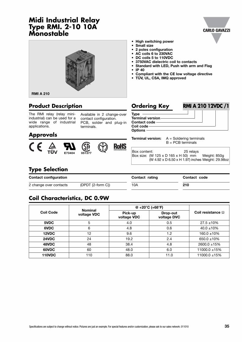
Midi Industrial Relay Type RMI. 2-10 10AHigh Inrush Monostable
• High switching power• Small size• Wide range of application• 10A switching capacity • 2 poles configuration• AC coils 6V to 380V• DC coils 6V to 240V• Standard with LED, Push arm and Flag• IP 40• Compliant with the CE low voltage directive• TÜV, UL, CSA, IMQ, RINA (marine) approved
RMI A 210
The RMI relay (relay mini-industrial) can be used for awide range of industrialapplications.
Product Description Ordering Key RMI A 210 12DC /1
Contact code
210
Contact rating
10A
Contact configuration
2 change over contacts (DPDT {2-form C})
Type Selection
Coil Characteristics, DC 0.9W
Available in 2 change-overcontact configuration. PCB, solder and plug-interminals.
Approvals
Coil Code Nominal voltage VDC
@ +20°C (+68°F)Coil resistance ΩPick-up
voltage VDC Min.Drop-out
voltage DVC Min.
6DC 6 4.5 0.6 40.0 ±10%
9DC 9 6.75 0.9 90 ±10%
12DC 12 9.0 1.2 160.0 ±10%
24DC 24 19.2 2.4 650.0 ±10%
36DC 36 25.0 3.6 1500.0 ±10%
48DC 48 38.4 4.8 2600.0 ±15%
100DC 100 80.0 10.0 11000.0 ±15%
110DC 110 88.0 11.0 11000.0 ±10%
220DC 220 165.0 22.0 42000.0 ±10%
240DC 240 180.0 24.0 64000.0 ±10%
E73404
RI N A
1
8 6
1
26 Specifications are subject to change without notice. Pictures are just an example. For special features and/or customization, please ask to our sales network. 011010
Box content: 20 relaysBox size: (W 240 x D 105 x H 38) mm Weight: 680g
(W 9.45 x D 4.13 x H 1.50) inches Weight: 23.99oz
Nominal coil power 0.9W DC / 1.2VA ACOperating time(At nominal voltage) 20ms max.Release time(At nominal voltage) 20ms max.Ambient temperature -55° to +70°C (-67° to +158°F)Vibration resistance 10 to 55Hz 1.0mm (0.04”)Construction Dust cover
Voltage DIP 5ms before turning OFFShock resistanceFunctional 100m/s2 /10g 11msDestructive 1000m/s2 /100gHumidity 35% to 95%
RH non-condensingTerminals PCB or Soldering Lugs
(Plug-in)Weight ~37g (~1.30oz)
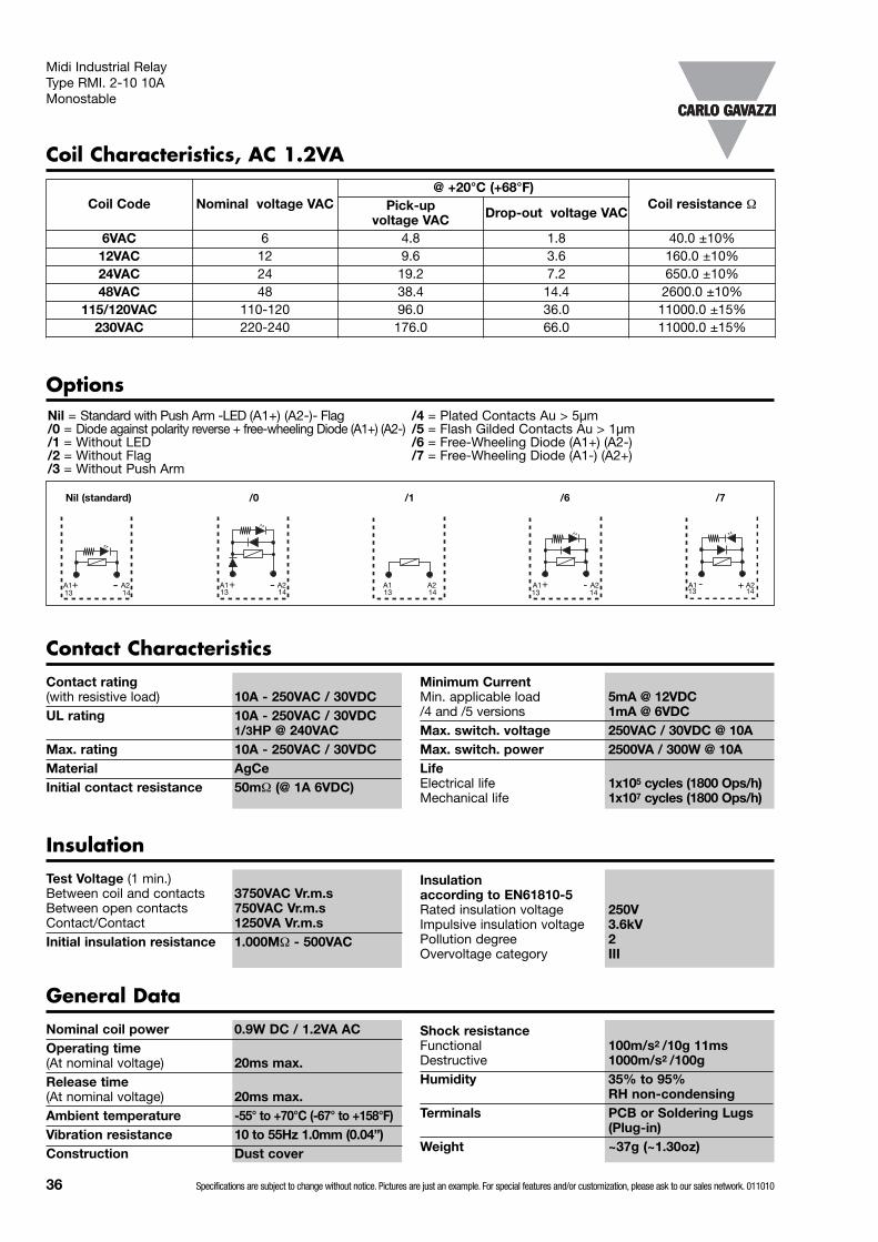
Contact Characteristics
Contact rating(with resistive load) 10A - 250VAC / 30VDCUL rating 10A - 250VAC / 30VDC
1/3HP @ 240VAC @ 60°C (160°F)Max. rating (5x10⁴ ops) 10A - 250VAC / 30VDCMaterial AgSn2In2O3
Initial contact resistance 50mΩ (@ 1A 6VDC)
Test Voltage (1 min.)Between coil and contacts 2000VAC Vr.m.sBetween open contacts 1000VAC Vr.m.sContact/Contact 1000VA Vr.m.sInitial insulation resistance 1.000MΩ - 500VAC
General Data
Insulation according to EN61810-5Rated insulation voltage 250VImpulsive insulation voltage 3.6kVPollution degree 2Overvoltage category III
Midi Industrial Relay Type RMI. 2-10 10AHigh Inrush Monostable
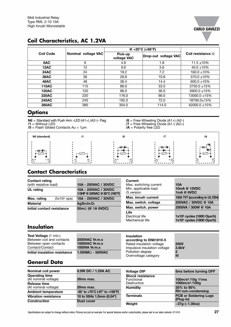
Coil Characteristics, AC 1.2VA
Nil = Standard with Push Arm -LED (A1+) (A2-)- Flag/1 = Without LED/5 = Flash Gilded Contacts Au > 1µm
Options
/1Nil (standard) /6 /7 /A
A2A1 A2A1 -+ A2A1 +-
CurrentMax. switching current 10AMin. applicable load 10mA @ 12VDC/5 version 1mA @ 6VDCMax. inrush current 105A TV7 (acconding to UL1054)Max. switch. voltage 250VAC / 30VDC @ 10AMax. switch. power 2500VA / 300W @ 10ALifeElectrical life 1x10⁵ cycles (1800 Ops/h)Mechanical life 1x10⁷ cycles (1800 Ops/h)
A2A1 A2A114131413141314131413
Coil Code Nominal voltage VAC@ +20°C (+68°F)
Coil resistance ΩPick-up voltage VAC Drop-out voltage VAC
6AC 6 4.8 1.8 11.5 ±10%12AC 12 9.6 3.6 40.0 ±10%24AC 24 19.2 7.2 160.0 ±10%36AC 36 28.8 10.8 370.0 ±10%48AC 48 38.4 14.4 600.0 ±10%110AC 110 88.0 33.0 3750.0 ±15%120AC 120 96.0 36.0 3900.0 ±15%220AC 220 176.0 66.0 13000.0 ±15%240AC 240 192.0 72.0 18790.0±15%380AC 380 304.0 114.0 42000.0 ±15%
Specifications are subject to change without notice. Pictures are just an example. For special features and/or customization, please ask to our sales network. 011010 27
/6 = Free-Wheeling Diode (A1+) (A2-)/7 = Free-Wheeling Diode (A1-) (A2+)/A = Polarity free LED
-+
Insulation

Diagrams 1 Coil Operating Range
UB
/ U
N
2.2
2.0
1.8
1.6
1.4
1.2
1.0
0.8
0.60 +10 +20 +30 +40 +50 +60 +70 +80(32) (+50) (+68) (+86) (+104) (+122) (+140) (+158) (+176)
Ambient temperature °C (°F)
2 Max. DC load breaking capacity
DC Current (A)
DC
vol
tage
(VD
C)
3 Electrical life
Num
ber
of
oper
atio
ns (X
104
ops)
Switching Current (A) inductive load
AC inductive load 250VAC COS ϕ = 0.4
DC inductive load 30VDC — = 7ms
L
R
500
100
50
10
00 1 2 3 4 5
Num
ber
of
oper
atio
ns (X
104
ops)
Switching Current (A) resistive load
500
100
50
10
00 2 4 6 8 10
DC resistive load 30VDC
AC resistive load 250VAC
300
200
100
60
50
40
30
20
100.1 0.2 0.3 1 2 10 20
Dimensions mm/inches
RMI . 2-10 . . .
28/1.10” 36/1.42”21
.5/0
.85”
4.5/0.17”6.4/
0.25”
2.2/
0.09
” x
0.5/
0.02
”
3.5/0.15”
4/0.16”
Midi Industrial Relay Type RMI. 2-10 10AHigh Inrush Monostable
PCB TerminalsRMI B
Soldering TerminalsRMI A
RMI . 2-10 . . .
Pin View mm/inches
PCB drilling pattern
RMI . 2-10 . . .
Wiring Diagram
13.2/0.51”
6.3/0.24”
Ø1.3/0.05
442
112
844
514
1241
911
14A2
13A1
BOTTOM VIEW
1/0.
04”
x 0.
5/0.
02”
6.3/0.24”
6.4/0.25”
4.1/0.16”
Bases and SocketsDIN rail sockets codes are ZMI2NA, ZMI4NA, ZMI2SA, ZMI4SA, ZMI2GA, ZMI4GA, ZR08 and ZDM14A details and specifications from page41 to 44 of industrial relays catalogue. PCB sockets codes are ZC15/2A, ZC15/4A, ZC15/2 and ZC15/4 details and specifications on page 46 of industrial relays catalogue.28 Specifications are subject to change without notice. Pictures are just an example. For special features and/or customization, please ask to our sales network. 011010

Specifications are subject to change without notice. Pictures are just an example. For special features and/or customization, please ask to our sales network. 011010 29
TypeTerminal version Contact code Coil codeOptions
Terminal version: A = Soldering terminalsB = PCB terminals
Midi Industrial Relay Type RMI. 3-7 7AHigh Inrush Monostable
• High switching power• Small size• Wide range of application• 7A switching capacity • 3 poles configuration• AC coils 6V to 380V• DC coils 6V to 240V• Standard with LED, Push arm and Flag• IP 40• Compliant with the CE low voltage directive• TÜV, UL, CSA, IMQ approved
RMI A 37
The RMI relay (relay mini-industrial) can be used for awide range of industrialapplications.
Product Description Ordering Key RMI A 37 12DC /1
Contact code
37
Contact rating
7A
Contact configuration
3 change over contacts (DPDT {2-form C})
Type Selection
Coil Characteristics, DC 0.9W
Available in 3 change-overcontact configuration. PCB, solder and plug-interminals.
Approvals
Coil Code Nominal voltage VDC
@ +20°C (+68°F)Coil resistance ΩPick-up
voltage VDCDrop-out
voltage DVC
5DC 5 3.75 0.5 27.5 ±10%
6DC 6 4.5 0.6 40.0 ±10%
9DC 9 6.75 0.9 90 ±10%
12DC 12 9.0 1.2 160.0 ±10%
24DC 24 19.2 2.4 650.0 ±10%
36DC 36 25.0 3.6 1500.0 ±10%
48DC 48 38.4 4.8 2600.0 ±15%
60DC 60 48.0 6.0 11000.0 ±15%
110DC 110 88.0 11.0 11000.0 ±10%
220DC 220 165.0 22.0 42000.0 ±10%
240DC 240 180.0 24.0 64000.0 ±10%
E73404 Box content: 20 relaysBox size: (W 240 x D 105 x H 38) mm Weight: 680g
(W 9.45 x D 4.13 x H 1.50) inches Weight: 23.99oz

30 Specifications are subject to change without notice. Pictures are just an example. For special features and/or customization, please ask to our sales network. 011010
Nominal coil power 0.9W DC / 1.2VA ACOperating time(At nominal voltage) 20ms max.Release time (At nominal voltage) 20ms max.Ambient temperature -55° to +70°C (-67° to +158°F)Vibration resistance 10 to 55Hz 1.0mm (0.04”)Construction Dust cover
Shock resistanceFunctional 100m/s2 /10g 11msDestructive 1000m/s2 /100gHumidity 35% to 95%
RH non-condensingTerminals PCB or Soldering Lugs
(Plug-in)Weight ~37g (~1.30oz)
Contact Characteristics
Contact rating(with resistive load) 7A - 250VAC / 30VDCUL rating 5A - 250VAC / 30VDC
1/6HP @ 240VAC @ 60°C (160°F)Max. rating (5x10⁴ ops) 7A - 250VAC / 30VDCMaterial AgSn2In2O3
Minimum CurrentMin. applicable load 10mA @ 12VDC/5 version 1mA @ 6VDC
InsulationTest Voltage (1 min.)Between coil and contacts 2000VAC Vr.m.sBetween open contacts 1000VAC Vr.m.sContact/Contact 1000VA Vr.m.sInitial insulation resistance 1.000MΩ - 500VAC
General Data
Insulation according to EN61810-5Rated insulation voltage 250VImpulsive insulation voltage 3.6kVPollution degree 2Overvoltage category III
Midi Industrial Relay Type RMI. 3-7 7AHigh Inrush Monostable
Coil Characteristics, AC 1.2VA
Max. inrush current 78A TV5 (acconding to UL1054)Max. switch. voltage 250VAC / 30VDC @ 7AMax. switch. power 2500VA / 300W @ 7ALifeElectrical life 1x10⁵ cycles (1800 Ops/h)Mechanical life 1x10⁷ cycles (1800 Ops/h)
Coil Code Nominal voltage VAC@ +20°C (+68°F)
Coil resistance ΩPick-up voltage VAC Drop-out voltage VAC
6AC 6 4.8 1.8 11.5 ±10%12AC 12 9.6 3.6 40.0 ±10%24AC 24 19.2 7.2 160.0 ±10%36AC 36 28.8 10.8 370.0 ±10%48AC 48 38.4 14.4 600.0 ±10%110AC 110 88.0 33.0 3750.0 ±15%120AC 120 96.0 36.0 3900.0 ±15%220AC 220 176.0 66.0 13000.0 ±15%240AC 240 192.0 72.0 18790.0±15%380AC 380 304.0 114.0 42000.0 ±15%
Nil = Standard with Push Arm -LED (A1+) (A2-)- Flag/1 = Without LED/5 = Flash Gilded Contacts Au > 1µm
Options
/1Nil (standard) /6 /7 /A
A2A1 A2A1 -+ A2A1 +-A2A1 A2A114131413141314131413
/6 = Free-Wheeling Diode (A1+) (A2-)/7 = Free-Wheeling Diode (A1-) (A2+)/A = Polarity free LED
-+

Diagrams 1 Coil Operating Range
UB
/ U
N
2.2
2.0
1.8
1.6
1.4
1.2
1.0
0.8
0.60 +10 +20 +30 +40 +50 +60 +70 +80(32) (+50) (+68) (+86) (+104) (+122) (+140) (+158) (+176)
Ambient temperature °C (°F)
2 Max. DC load breaking capacity
DC Current (A)
DC
vol
tage
(VD
C)
3 Electrical life
Num
ber
of
oper
atio
ns (X
104
ops)
Switching Current (A) inductive load
AC inductive load 250VAC COS ϕ = 0.4
DC inductive load 30VDC — = 7ms
L
R
500
100
50
10
00 0.5 1 1.5 2 2.5
Num
ber
of
oper
atio
ns (X
104
ops)
Switching Current (A) resistive load
500
100
50
10
00 2 4 6 8 10
DC resistive load 30VDC
AC resistive load 250VAC
300
200
100
60
50
40
30
20
100.1 0.2 0.3 1 2 10 20
Dimensions mm/inches
RMI . 3-7 . . .
28/1.10” 36/1.42”
21.5
/0.8
5”
4.5/0.17”6.4/
0.25”
2.2/
0.09
” x
0.5/
0.02
”
3.5/0.15”
4/0.16”
Midi Industrial Relay Type RMI. 3-7 7AHigh Inrush Monostable
PCB TerminalsRMI B
Soldering TerminalsRMI A
Pin View mm/inches
RMI . 3-7 . . .
Wiring Diagram
3
1
6
4
9
7
11
10
BOTTOM VIEW
1/0.
04”
x 0.
5/0.
02”
RMI . 3-7 . . .
6.6/0.085”
PCB drilling pattern
13.2/0.51”
6.3/0.24” Ø1.3/0.05
6.3/0.24”
6.4/0.25”
4.1/0.16”
258
Bases and SocketsDIN rail sockets code is ZMI3SA details and specifications on page 42 of industrial relays catalogue.
Specifications are subject to change without notice. Pictures are just an example. For special features and/or customization, please ask to our sales network. 011010 31

TypeTerminal version Contact code Coil codeOptions
Terminal version: A = Soldering terminalsB = PCB terminals
Midi Industrial Relay Type RMI. 4-5 5AHigh Inrush Monostable
• High switching power• Small size• Wide range of application• 5A switching capacity • 4 poles configuration• AC coils 6V to 380V• DC coils 6V to 240V• Standard with LED, Push arm and Flag• IP 40• Complain with the CE low voltage directive• TÜV, UL, CSA, IMQ, RINA (marine) approved
RMI A 45
The RMI relay (relay mini-industrial) can be used for awide range of industrialapplications.
Product Description Ordering Key RMI A 45 12DC /1
Contact code
45
Contact rating
5A
Contact configuration
4 change over contacts (4PDT {4-form C})
Type Selection
Available in 4 change-overcontact configuration. PCB, solder and plug-interminals.
Approvals
Coil Characteristics, DC 0.9W
Coil Code Nominal voltage VDC
@ +20°C (+68°F)Coil resistance ΩPick-up
voltage VDC Min.Drop-out
voltage VDC Min.
6DC 6 4.5 0.6 40.0 ±10%
9DC 9 6.75 0.9 90 ±10%
12DC 12 9.0 1.2 160.0 ±10%
24DC 24 19.2 2.4 650.0 ±10%
36DC 36 25.0 3.6 1500.0 ±10%
48DC 48 38.4 4.8 2600.0 ±15%
100DC 100 80.0 10.0 11000.0 ±15%
110DC 110 88.0 11.0 11000.0 ±10%
220DC 220 165.0 22.0 42000.0 ±10%
240DC 240 180.0 24.0 64000.0 ±10%
E73404
RI N A
1
8 6
1
32 Specifications are subject to change without notice. Pictures are just an example. For special features and/or customization, please ask to our sales network. 011010
Box content: 20 relaysBox size: (W 240 x D 105 x H 38) mm Weight: 680g
(W 9.45 x D 4.13 x H 1.50) inches Weight: 23.99oz

Contact CharacteristicsContact rating(with resistive load) 5A - 250VACUL rating 5A - 250VAC/30VDC
1/6HP @ 240VAC @ 60°C (160°F)Max. rating (5x10⁴ ops) 5A - 250VAC / 30VDCMaterial AgSn2In2O3
Minimum CurrentMin. applicable load 10mA @ 12VDC/5 version 1mA @ 6VDC
Initial contact resistance 50mΩ (@ 1A 6VDC)Max. inrush current 51A TV3 (acconding to UL1054)Max. switch. voltage 250VAC / 30VDC @ 5AMax. switch. power 1250VA / 150W @ 5ALifeElectrical life 1x10⁵ cycles (1800 Ops/h)Mechanical life 1x10⁷ cycles (1800 Ops/h)
InsulationTest Voltage (1 min.)Between coil and contacts 2000VAC Vr.m.sBetween open contacts 1000VAC Vr.m.sContact/Contact 1000VA Vr.m.sInitial insulation resistance 1.000MΩ - 500VAC
General DataNominal coil power 0.9W DC / 1.2VA ACOperating time(At nominal voltage) 25ms max.Release time(At nominal voltage) 25ms max.Ambient temperature -55° to +70°C (-67° to +158°F)Vibration resistance 10 to 55Hz 1.5mm (0.06”)Construction Dust cover
Shock resistanceFunctional 100m/s2 /10gDestructive 1000m/s2 /100gHumidity 35% to 95%
RH non-condensingTerminals PCB or Soldering Lugs
(Plug-in)Weight ~37g (~1.30oz)
Midi Industrial Relay Type RMI. 4-5 5AHigh Inrush Monostable
Insulation according to EN61810-5Rated insulation voltage 250VImpulsive insulation voltage 3.6kVPollution degree 2Overvoltage category III
Coil Characteristics, AC 1.2VA
Coil Code Nominal voltage VAC
@ +20°C (+68°F)Coil
resistance ΩPick-up voltage VAC
Drop-out voltage VAC
6AC 6 4.8 1.8 11.5 ±10%12AC 12 9.6 3.6 40.0 ±10%24AC 24 19.2 7.2 160.0 ±10%36AC 36 28.8 10.8 370.0 ±10%48AC 48 38.4 14.4 600.0 ±10%110AC 110 88.0 33.0 3750.0 ±15%120AC 120 96.0 36.0 3900.0 ±15%220AC 220 176.0 66.0 13000.0 ±15%240AC 240 192.0 72.0 18790.0±15%380AC 380 304.0 114.0 42000.0 ±15%
Specifications are subject to change without notice. Pictures are just an example. For special features and/or customization, please ask to our sales network. 011010 33
Nil = Standard with Push Arm -LED (A1+) (A2-)- Flag/1 = Without LED/5 = Flash Gilded Contacts Au > 1µm
Options
/1Nil (standard) /6 /7 /A
A2A1 A2A1 -+ A2A1 +-A2A1 A2A114131413141314131413
/6 = Free-Wheeling Diode (A1+) (A2-)/7 = Free-Wheeling Diode (A1-) (A2+)/A = Polarity free LED
-+

RMI . 4-5 . . .
Pin View mm/inches
RMI . 4-5 . . .
Wiring Diagram
442
112
844
514
1241
911
14A2
13A1
4.4/0.17”
222
624
1021
332
734
1131
Midi Industrial Relay Type RMI. 4-5 5AHigh Inrush Monostable
Diagrams 1 Coil Operating Range
UB
/ U
N
2.2
2.0
1.8
1.6
1.4
1.2
1.0
0.8
0.60 +10 +20 +30 +40 +50 +60 +70 +80(32) (+50) (+68) (+86) (+104) (+122) (+140) (+158) (+176)
Ambient temperature °C (°F)
2 Max. DC load breaking capacity
DC Current (A)
DC
vol
tage
(VD
C)
3 Electrical life
Num
ber
of
oper
atio
ns (X
104
ops)
Switching Current (A) inductive load
AC inductive load 250VAC COS ϕ = 0.4
DC inductive load 30VDC — = 7ms
L
R
500
100
50
10
00 0.5 1.0 1.5 2.0
Num
ber
of
oper
atio
ns (X
104
ops)
Switching Current (A) resistive load
500
100
50
10
00 1 2 3 4 5 6 7 8 9 10
DC resistive load 30VDC
AC resistive load 250VAC
300
200
100
60
50
40
30
20
100.1 0.2 0.3 1 2 10 20
Dimensions mm/inches
RMI . 4-5 . . .
PCB TerminalsRMI B
Soldering TerminalsRMI A
PCB drilling patternBOTTOM VIEW
28/1.10” 36/1.42”21
.5/0
.85”
4.5/0.17”6.4/
0.25”
2.2/
0.09
” x
0.5/
0.02
”
3.5/0.15”
4/0.16”
1/0.
04”
x 0.
5/0.
02”
13.2/0.51”
6.3/0.24” Ø1.3/0.05
6.3/0.24”
6.4/0.25”
4.1/0.16”
Bases and SocketsDIN rail sockets codes are ZMI4NA, ZMI4SA, ZMI4GA and ZDM14A details and specifications from page 41 to 44 of industrial relays catalogue. PCB sockets codes are ZC15/4A and ZC15/4 details and specifications on page 46 of industrial relays catalogue.34 Specifications are subject to change without notice. Pictures are just an example. For special features and/or customization, please ask to our sales network. 011010
TypeTerminal version Contact code Coil codeOptions
Terminal version: A = Soldering terminalsB = PCB terminals
Midi Industrial Relay Type RMI. 2-10 10AMonostable
• High switching power• Small size• 2 poles configuration• AC coils 6 to 230VAC• DC coils 5 to 110VDC• 3750VAC dielectric coil to contacts• Standard with LED, Push with arm and Flag• IP 40• Compliant with the CE low voltage directive• TÜV, UL, CSA, IMQ approved
RMI A 210
The RMI relay (relay mini-industrial) can be used for awide range of industrialapplications.
Product Description Ordering Key RMI A 210 12VDC /1
Contact code
210
Contact rating
10A
Contact configuration
2 change over contacts (DPDT {2-form C})
Type Selection
Coil Characteristics, DC 0.9W
Available in 2 change-overcontact configuration. PCB, solder and plug-interminals.
Approvals
Coil Code Nominal voltage VDC
@ +20°C (+68°F)Coil resistance ΩPick-up
voltage VDCDrop-out
voltage DVC
5VDC 5 4.0 0.5 27.5 ±10%
6VDC 6 4.8 0.6 40.0 ±10%
12VDC 12 9.6 1.2 160.0 ±10%
24VDC 24 19.2 2.4 650.0 ±10%
48VDC 48 38.4 4.8 2600.0 ±15%
60VDC 60 48.0 6.0 11000.0 ±15%
110VDC 110 88.0 11.0 11000.0 ±15%
E73404
Specifications are subject to change without notice. Pictures are just an example. For special features and/or customization, please ask to our sales network. 011010 35
Box content: 25 relaysBox size: (W 125 x D 165 x H 50) mm Weight: 850g
(W 4.92 x D 6.50 x H 1.97) inches Weight: 29.98oz
051377
36 Specifications are subject to change without notice. Pictures are just an example. For special features and/or customization, please ask to our sales network. 011010
Nominal coil power 0.9W DC / 1.2VA ACOperating time(At nominal voltage) 20ms max.Release time (At nominal voltage) 20ms max.Ambient temperature -55° to +70°C (-67° to +158°F)Vibration resistance 10 to 55Hz 1.0mm (0.04”)Construction Dust cover
Shock resistanceFunctional 100m/s2 /10g 11msDestructive 1000m/s2 /100gHumidity 35% to 95%
RH non-condensingTerminals PCB or Soldering Lugs
(Plug-in)Weight ~37g (~1.30oz)
Contact CharacteristicsContact rating(with resistive load) 10A - 250VAC / 30VDCUL rating 10A - 250VAC / 30VDC
1/3HP @ 240VACMax. rating 10A - 250VAC / 30VDCMaterial AgCeInitial contact resistance 50mΩ (@ 1A 6VDC)
InsulationTest Voltage (1 min.)Between coil and contacts 3750VAC Vr.m.sBetween open contacts 750VAC Vr.m.sContact/Contact 1250VA Vr.m.sInitial insulation resistance 1.000MΩ - 500VAC
General Data
Insulation according to EN61810-5Rated insulation voltage 250VImpulsive insulation voltage 3.6kVPollution degree 2Overvoltage category III
Midi Industrial Relay Type RMI. 2-10 10AMonostable
Coil Characteristics, AC 1.2VA
Nil = Standard with Push Arm -LED (A1+) (A2-)- Flag /4 = Plated Contacts Au > 5µm/0 = Diode against polarity reverse + free-wheeling Diode (A1+) (A2-) /5 = Flash Gilded Contacts Au > 1µm/1 = Without LED /6 = Free-Wheeling Diode (A1+) (A2-)/2 = Without Flag /7 = Free-Wheeling Diode (A1-) (A2+)/3 = Without Push Arm
Options
/1Nil (standard) /6/0 /7
A2A1 A2A1 A2A1 -+ A2A1 +-
Minimum CurrentMin. applicable load 5mA @ 12VDC/4 and /5 versions 1mA @ 6VDCMax. switch. voltage 250VAC / 30VDC @ 10AMax. switch. power 2500VA / 300W @ 10ALifeElectrical life 1x10⁵ cycles (1800 Ops/h)Mechanical life 1x10⁷ cycles (1800 Ops/h)
A2A114131413141314131413
Coil Code Nominal voltage VAC@ +20°C (+68°F)
Coil resistance ΩPick-up voltage VAC Drop-out voltage VAC
6VAC 6 4.8 1.8 40.0 ±10%12VAC 12 9.6 3.6 160.0 ±10%24VAC 24 19.2 7.2 650.0 ±10%48VAC 48 38.4 14.4 2600.0 ±10%
115/120VAC 110-120 96.0 36.0 11000.0 ±15%230VAC 220-240 176.0 66.0 11000.0 ±15%
-+ -+

Diagrams 1 Coil Operating Range
UB
/ U
N
2.2
2.0
1.8
1.6
1.4
1.2
1.0
0.8
0.60 +10 +20 +30 +40 +50 +60 +70 +80(32) (+50) (+68) (+86) (+104) (+122) (+140) (+158) (+176)
Ambient temperature °C (°F)
3 Electrical life
Num
ber
of
oper
atio
ns (X
104
ops)
Switching Current (A) inductive load
AC inductive load 250VAC COS ϕ = 0.4
DC inductive load 30VDC — = 7ms
L
R
500
100
50
10
00 1 2 3 4 5
Num
ber
of
oper
atio
ns (X
104
ops)
Switching Current (A) resistive load
500
100
50
10
00 2 4 6 8 10
DC resistive load 30VDC
AC resistive load 250VAC
Dimensions mm/inches
RMI . 2-10 . . .
28/1.10” 36/1.42”
21.5
/0.8
5”
4.5/0.17”5.8/
0.23”
2.2/
0.09
” x
0.5/
0.02
”
3.5/0.15”
4/0.16”
Midi Industrial Relay Type RMI. 2-10 10AMonostable
PCB TerminalsRMI B
Soldering TerminalsRMI A
RMI . 2-10 . . .
Pin View mm/inches
PCB drilling pattern
RMI . 2-10 . . .
Wiring Diagram
13.2/0.51”
6.3/0.24”
Ø1.3/0.05
442
112
844
514
1241
911
14A2
13A1
BOTTOM VIEW
1/0.
04”
x 0.
5/0.
02”
6.3/0.24”
6.4/0.25”
4.1/0.16”
Bases and SocketsDIN rail sockets codes are ZMI2NA, ZMI4NA, ZMI2SA, ZMI4SA, ZMI2GA, ZMI4GA, ZR08 and ZDM14A details and specifications from page41 to 44 of industrial relays catalogue. PCB sockets codes are ZC15/2A, ZC15/4A, ZC15/2 and ZC15/4 details and specifications on page 46 of industrial relays catalogue.Specifications are subject to change without notice. Pictures are just an example. For special features and/or customization, please ask to our sales network. 011010 37
Sw
itchi
ng c
urre
nt (A
)
Max. switching current
Switching voltage (V)10 100 1000
30
10
5
1
0.5
0.1
Resistiveload AC
AC(cosϕ = 0.4)
DC L/R = 7ms
Resistiveload DC

38 Specifications are subject to change without notice. Pictures are just an example. For special features and/or customization, please ask to our sales network. 011010
TypeTerminal version Contact code Coil codeOptions
Terminal version: A = Soldering terminalsB = PCB terminals
Midi Industrial Relay Type RMI. 4-5 5AMonostable
• High switching power• Small size• 4 poles configuration• AC coils 6 to 230VAC• DC coils 5 to 110VDC• 3750VAC dielectric coil to contacts• Standard with LED, Push with arm and Flag• IP 40• Complain with the CE low voltage directive• TÜV, UL, CSA, IMQ approved
RMI A 45
The RMI relay (relay mini-industrial) can be used for awide range of industrialapplications.
Product Description Ordering Key RMI A 45 12VDC /1
Contact code
45
Contact rating
5A
Contact configuration
4 change over contacts (4PDT {4-form C})
Type Selection
Available in 4 change-overcontact configuration. PCB, solder and plug-interminals.
Approvals
Coil Characteristics, DC 0.9W
Coil Code Nominal voltage VDC
@ +20°C (+68°F)Coil resistance ΩPick-up
voltage VDCDrop-out
voltage VDC
5VDC 5 4.0 0.5 27.5 ±10%
6VDC 6 4.8 0.6 40.0 ±10%
12VDC 12 9.6 1.2 160.0 ±10%
24VDC 24 19.2 2.4 650.0 ±10%
48VDC 48 38.4 4.8 2600.0 ±15%
60VDC 60 48.0 6.0 11000.0 ±15%
110VDC 110 88.0 11.0 11000.0 ±15%
E73404 Box content: 25 relaysBox size: (W 125 x D 165 x H 50) mm Weight: 850g
(W 4.92 x D 6.50 x H 1.97) inches Weight: 29.98oz
051377
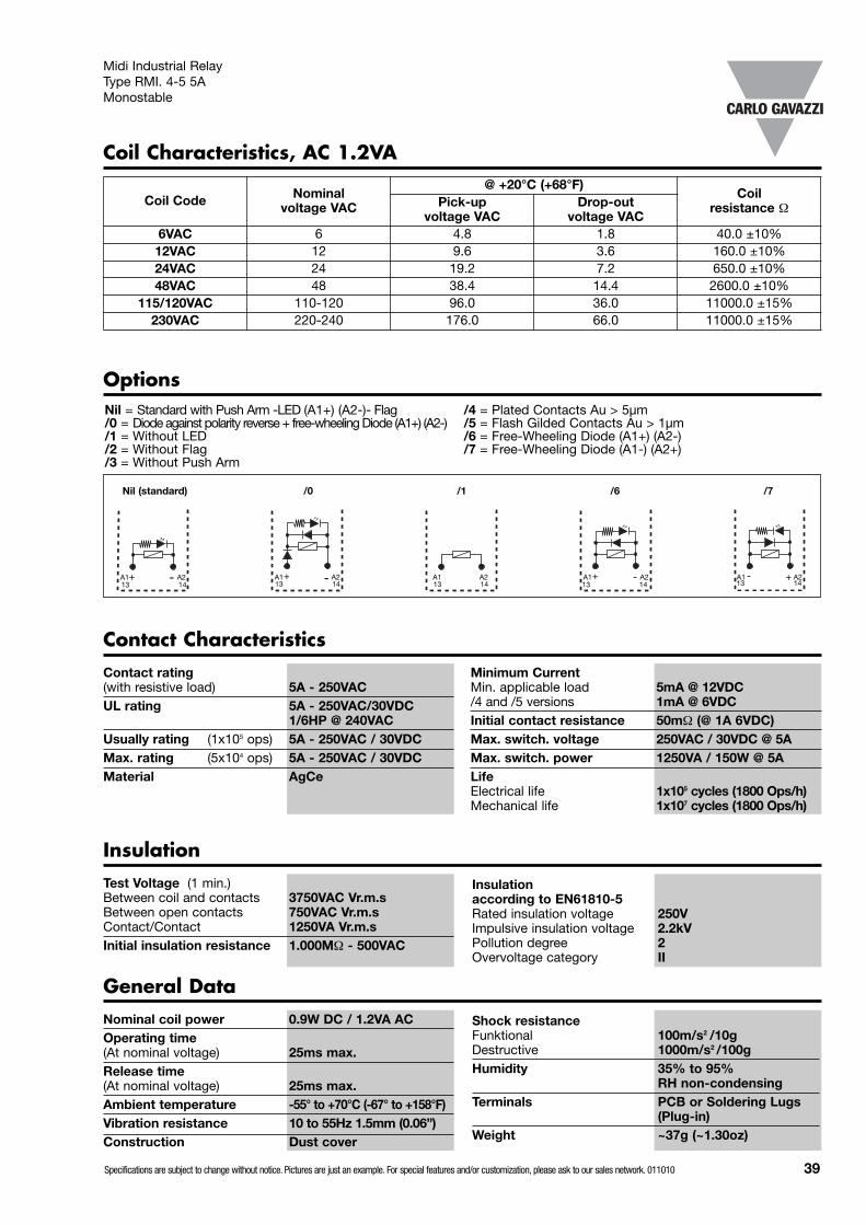
Contact CharacteristicsContact rating(with resistive load) 5A - 250VACUL rating 5A - 250VAC/30VDC
1/6HP @ 240VACUsually rating (1x10⁵ ops) 5A - 250VAC / 30VDCMax. rating (5x10⁴ ops) 5A - 250VAC / 30VDCMaterial AgCe
Minimum CurrentMin. applicable load 5mA @ 12VDC/4 and /5 versions 1mA @ 6VDCInitial contact resistance 50mΩ (@ 1A 6VDC)Max. switch. voltage 250VAC / 30VDC @ 5AMax. switch. power 1250VA / 150W @ 5ALifeElectrical life 1x10⁵ cycles (1800 Ops/h)Mechanical life 1x10⁷ cycles (1800 Ops/h)
InsulationTest Voltage (1 min.)Between coil and contacts 3750VAC Vr.m.sBetween open contacts 750VAC Vr.m.sContact/Contact 1250VA Vr.m.sInitial insulation resistance 1.000MΩ - 500VAC
General DataNominal coil power 0.9W DC / 1.2VA ACOperating time(At nominal voltage) 25ms max.Release time(At nominal voltage) 25ms max.Ambient temperature -55° to +70°C (-67° to +158°F)Vibration resistance 10 to 55Hz 1.5mm (0.06”)Construction Dust cover
Shock resistanceFunktional 100m/s2 /10gDestructive 1000m/s2 /100gHumidity 35% to 95%
RH non-condensingTerminals PCB or Soldering Lugs
(Plug-in)Weight ~37g (~1.30oz)
Midi Industrial Relay Type RMI. 4-5 5AMonostable
Insulation according to EN61810-5Rated insulation voltage 250VImpulsive insulation voltage 2.2kVPollution degree 2Overvoltage category II
Coil Characteristics, AC 1.2VA
Coil Code Nominal voltage VAC
@ +20°C (+68°F)Coil
resistance ΩPick-up voltage VAC
Drop-out voltage VAC
6VAC 6 4.8 1.8 40.0 ±10%12VAC 12 9.6 3.6 160.0 ±10%24VAC 24 19.2 7.2 650.0 ±10%48VAC 48 38.4 14.4 2600.0 ±10%
115/120VAC 110-120 96.0 36.0 11000.0 ±15%230VAC 220-240 176.0 66.0 11000.0 ±15%
Specifications are subject to change without notice. Pictures are just an example. For special features and/or customization, please ask to our sales network. 011010 39
Nil = Standard with Push Arm -LED (A1+) (A2-)- Flag /4 = Plated Contacts Au > 5µm/0 = Diode against polarity reverse + free-wheeling Diode (A1+) (A2-) /5 = Flash Gilded Contacts Au > 1µm/1 = Without LED /6 = Free-Wheeling Diode (A1+) (A2-)/2 = Without Flag /7 = Free-Wheeling Diode (A1-) (A2+)/3 = Without Push Arm
Options
/1Nil (standard) /6/0 /7
A2A1 -+ A2A1 A2A1 -+ A2A1 +-A2A114131413141314131413
-+
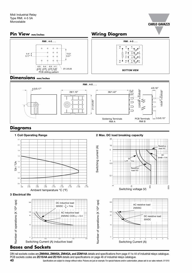
40 Specifications are subject to change without notice. Pictures are just an example. For special features and/or customization, please ask to our sales network. 011010
RMI . 4-5 . . .
Pin View mm/inches
RMI . 4-5 . . .
Wiring Diagram
442
112
844
514
1241
911
14A2
13A1
4.4/0.17”
222
624
1021
332
734
1131
Midi Industrial Relay Type RMI. 4-5 5AMonostable
Diagrams
0.1
0.51
5
10
30
1000
100
100
1 Coil Operating Range
UB
/ U
N
2.2
2.0
1.8
1.6
1.4
1.2
1.0
0.8
0.60 +10 +20 +30 +40 +50 +60 +70 +80(32) (+50) (+68) (+86) (+104) (+122) (+140) (+158) (+176)
Ambient temperature °C (°F)
2 Max. DC load breaking capacity
3 Electrical life
Num
ber
of
oper
atio
ns (X
104
ops)
Switching Current (A) inductive load
AC inductive load 250VAC COS ϕ = 0.4
DC inductive load 30VDC — = 7ms
L
R
500
100
50
10
00 0.5 1.0 1.5 2.0
Num
ber
of
oper
atio
ns (X
104
ops)
Switching Current (A)
500
100
50
10
0
0 1 2 3 4 5 6 7 8 9 10
DC resistive load 30VDC
AC resistive load 250VAC
Dimensions mm/inches
RMI . 4-5 . . .
PCB TerminalsRMI B
Soldering TerminalsRMI A
PCB drilling patternBOTTOM VIEW
28/1.10” 36/1.42”21
.5/0
.85”
4.5/0.17”5.8/
0.23”
2.2/
0.09
” x
0.5/
0.02
”
3.5/0.15”
4/0.16”
1/0.
04”
x 0.
5/0.
02”
13.2/0.51”
6.3/0.24” Ø1.3/0,05
6.3/0.24”
6.4/0.25”
4.1/0.16”
Bases and SocketsDIN rail sockets codes are ZMI4NA, ZMI4SA, ZMI4GA, and ZDM14A details and specifications from page 41 to 44 of industrial relays catalogue. PCB sockets codes are ZC15/4A and ZC15/4 details and specifications on page 46 of industrial relays catalogue.
Resistiveload AC
AC(cosϕ = 0.4)
DC L/R = 7ms
Resistiveload DCS
witc
hing
cur
rent
(A)
Switching voltage (V)

Sockets for RMI Relays
General dataSocket Material PA66 +GF – V2Socket colour RAL 7035 / Pantone 1CContact Material Cu NiContact surface 5µm tin platedTerminals 8µm zinc plated steelTerminal type Screw cageScrews 5µm nickel plated 8.8 steelScrew type M3 with combi head
(slotted, Philips Gr.1, Pozi)
Ratings 10A 300VACUL Rating 10A x 2 or 5A x 4 @ 300VACOperating temp. -25° to +70°C (-13° to +158°F)Insulation voltage >4kVCreepage and Clearance Gr.C250, VDE 0110b / 2.79Maximum Screw torque 1.0N/mMax Wire sectionFlex / compact wire 2 x 2.5mm2 (14AWG)Cable End 2 x 1.5mm2 (16AWG)Terminal Protection degree IP 20 (EN60529)
ZMI 2NA – ZMI 4NA
Optional Accessories (to be ordered separately if required)Metal spare hold down Spring SZMI36M (see on page 82)Plastic spare hold down Spring SZMI35 (see on page 82)Plastic spare hold down Spring 6.73.00.61.4 (see on page 82)
Labels 6.73.00.61.300 Bridging bar ZMI-BB (see on page 85)Modules (see on page 79)
Ordering code 2 contacts version for RMI A 2 10 xxx with Plastic hold down spring : ZMI2NA / ZMI4NAOrdering code 4 contacts version for RMI A 4 5 xxx with Plastic hold down spring : ZMI4NAOrdering code 2 contacts version for RMI A 2 10 xxx with Metal hold down spring : ZMI2NA-M / ZMI4NA-MOrdering code 4 contacts version for RMI A 4 5 xxx with Metal hold down spring : ZMI4NA-M
40/1.57”75/2.95”
75/2.95”
27/1
.06”
22.5
/0.8
8”
3.2/0.13”
PLATE
9/0.35”
72/2.83”
LATERAL VIEW
TOP VIEW
ZMI 4NA
9
10
11
21
COM
1131
1241
5
6
NO
7
8
13
14
14
24
34
44
1
2
NC
3
4
12
22
32
42
A1
A2
mm/inches
mm/inches
ApprovalsR
I N A
1
8 6
1
Box content: 10 sockets, 10 labels, 10 Plastic hold down springsBox size: (W 155 x D 165 x H 70) mm Weight: 750g
(W 6.10 x D 6.50 x H 2.75) inches Weight: 26.45oz
Specifications are subject to change without notice. Pictures are just an example. For special features and/or customization, please ask to our sales network. 011010 41
E73404

42 Specifications are subject to change without notice. Pictures are just an example. For special features and/or customization, please ask to our sales network. 011010
Sockets for RMI Relays
General dataSocket material PA66 +GF – V2Socket colour RAL 7035 / Pantone 1CContact material Cu NiContact surface 5µm tin platedTerminals 8µm zinc plated steelTerminal type Screw cageScrews 5µm nickel plated 8.8 steelScrew type M3 with combi head
(slotted, Philips Gr.1, Pozi)Ratings 10A x 2 or 5A x 4 @ 300VAC
UL rating 10A 300VACInsulation voltage >4kVOperating temp. -25° to +85°C (-13° to +185°F)Creepage and clearance Gr.C250, VDE 0110b /2.79Maximum screw torque 1N/mMax wire sectionFlex / compact wire 0.5-2.5mm2 (20AWG - 14AWG)Cable End 2 x 1.5mm2 (16AWG)Terminal protection degree IP 20 (EN60529)
ZMI 2SA – ZMI 3SA - ZMI 4SA
Optional Accessories (to be ordered separately if required)Metal Hold Down Springs SZMI36M (see on page 82)Plastic spare hold down Spring SZMI35 (see on page 82)Plastic spare hold down Spring 6.73.00.61.4 (see on page 82)
Labels 6.73.00.61.300 Bridging bar ZMI-BB (see on page 85)Modules (see on page 79)
Ordering code 2 contacts version for RMI A 2 10 xxx : ZMI2SA / ZMI4SAOrdering code 3 contacts version for RMI A 3 7 xxx : ZMI3SAOrdering code 4 contacts version for RMI A 4 5 xxx : ZMI4SA
38.3/1.51”
77/3.03”
27/1
.06”
22.8
/0.8
9”
3.15/0.12”
LATERAL VIEW
ZMI 2SA - ZMI 4SA TOP VIEW
24/0
.94”
42.6
/1.6
8”
62/2
.44”
81.6
/3.2
1”29
.1/1
.15”
ZMI 4SA
119 145 121
2110 246 222
3233473111
4112 448 424
A1
A2
13
14
A2 14
COM NO NC
ZMI 3SA TOP VIEW
11 144 121
22458
931 346 3
A1
A2
13
14
A2 14
COM NO NC
module
spring
77/3.03”
27/1
.06”
22.8
/0.8
9”
3.15/0.12”
mm/inches
mm/inches
mm/inches
Approvals
E73404
Box content: 10 sockets, 10 labels, 10 Plastic hold down springsBox size: (W 155 x D 165 x H 70) mm Weight: 750g
(W 6.10 x D 6.50 x H 2.75) inches Weight: 26.45oz

Specifications are subject to change without notice. Pictures are just an example. For special features and/or customization, please ask to our sales network. 011010 43
Sockets for RMI Relays
General dataSocket material PA6 + GF – V2Socket colour RAL 7035 / Pantone 1CContact material CuZn33Contact surface 6µm nickel platedTerminal type Screw cageScrews 5µm nickel plated 8.8 steelScrew type M3 with combi head
(slotted, Philips Gr.1, Pozi)Ratings @ 300VAC 12A
Operating temp. -25° to +85°C (-13° to +185°F)Insulation voltage >3kVSeparation between VDE0106/101contacts and contact coil Maximum screw torque 0.8N/mMax wire sectionFlex / compact wire 2 x 1.5mm2 (16AWG)Cable End 2 x 1.5mm2 (16AWG)Terminal protection degree IP 20B (EN60529)
ZR08
LATERAL VIEW
TOP VIEW
ZR08
5 14
NO
8 44
NC
4
12
42
911
COM
1241
13
14
1 A1
A2
29/1
.14”
9/0.35”11/0.43” 11/0.43” 11/0.43”
6/0.24”
24.5
/0.9
6”
69/2.72”
mm/inches
mm/inches
Optional Accessories (to be ordered separately if required)Metal hold down Spring SZMI36M (see on page 82)
Labels 6.73.00.61.300Modules (see on page 79)
Approvals
Ordering code 2 contacts version for RMI A 2 10 with metal hold down spring: ZR08
Box content: 10 sockets, 10 labels, 10 Hold down springsBox size: (W 73 x D 66 x H 150) mm Weight: 560g
(W 2.87 x D 2.60 x H 5.91) inches Weight: 19.75oz
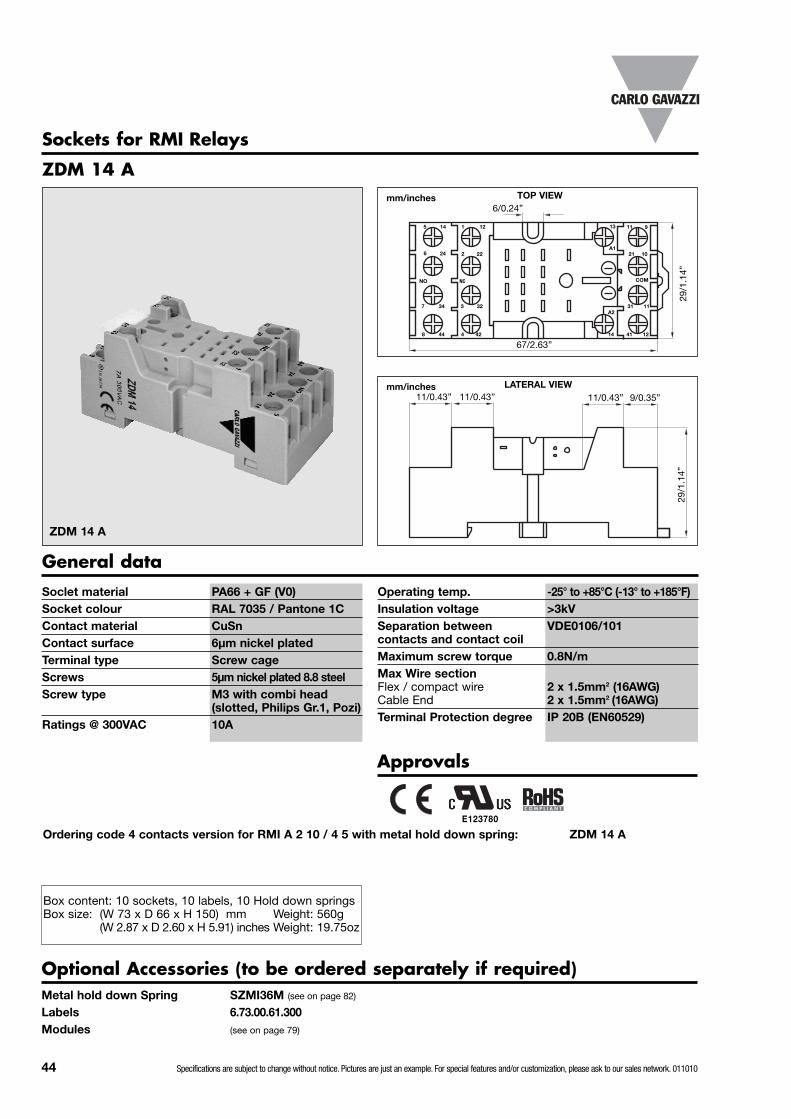
44 Specifications are subject to change without notice. Pictures are just an example. For special features and/or customization, please ask to our sales network. 011010
Sockets for RMI Relays
General dataSoclet material PA66 + GF (V0)Socket colour RAL 7035 / Pantone 1CContact material CuSnContact surface 6µm nickel platedTerminal type Screw cageScrews 5µm nickel plated 8.8 steelScrew type M3 with combi head
(slotted, Philips Gr.1, Pozi)Ratings @ 300VAC 10A
Operating temp. -25° to +85°C (-13° to +185°F)Insulation voltage >3kVSeparation between VDE0106/101contacts and contact coil Maximum screw torque 0.8N/mMax Wire sectionFlex / compact wire 2 x 1.5mm2 (16AWG)Cable End 2 x 1.5mm2 (16AWG)Terminal Protection degree IP 20B (EN60529)
ZDM 14 A
LATERAL VIEW
TOP VIEW
ZDM 14 A
5
6
14
24
NO
7
8
34
44
2
NC
3
4
12
22
32
42
9
10
11
21
COM
1131
1241
13
14
1
A1
A2
29/1
.14”
9/0.35”11/0.43” 11/0.43” 11/0.43”
6/0.24”
29/1
.14”
67/2.63”
mm/inches
mm/inches
Optional Accessories (to be ordered separately if required)Metal hold down Spring SZMI36M (see on page 82)
Labels 6.73.00.61.300Modules (see on page 79)
Approvals
Ordering code 4 contacts version for RMI A 2 10 / 4 5 with metal hold down spring: ZDM 14 A
Box content: 10 sockets, 10 labels, 10 Hold down springsBox size: (W 73 x D 66 x H 150) mm Weight: 560g
(W 2.87 x D 2.60 x H 5.91) inches Weight: 19.75oz
E123780

Specifications are subject to change without notice. Pictures are just an example. For special features and/or customization, please ask to our sales network. 011010 45
Installation Operations
MODULE
SPRING FOR RELAY
PLATE
ZMI ASSEMBLY VIEW RELAY REMOVAL
PLATE
RELAY
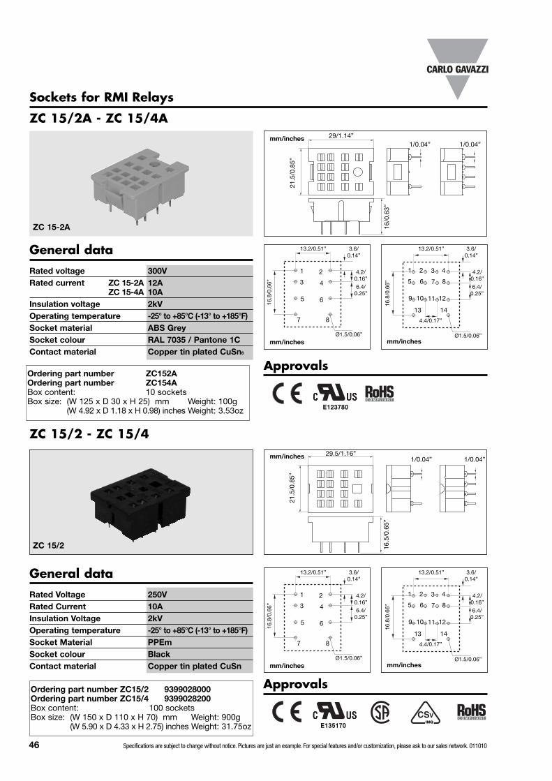
46 Specifications are subject to change without notice. Pictures are just an example. For special features and/or customization, please ask to our sales network. 011010
Sockets for RMI Relays
ZC 15/2A - ZC 15/4A
General dataRated voltage 300VRated current ZC 15-2A 12A
ZC 15-4A 10AInsulation voltage 2kVOperating temperature -25° to +85°C (-13° to +185°F)Socket material ABS GreySocket colour RAL 7035 / Pantone 1CContact material Copper tin plated CuSn6
16/0
.63”
29/1.14”
21.5
/0.8
5”
1 2
3 4
5 6
7 8
3.6/0.14”
4.2/0.16”6.4/
0.25”
16.8
/0.6
6”
13.2/0.51”
Ø1.5/0.06”
1/0.04”
ZC 15-2A
ZC 15/2 - ZC 15/4
General dataRated Voltage 250VRated Current 10AInsulation Voltage 2kVOperating temperature -25° to +85°C (-13° to +185°F)Socket Material PPEmSocket colour BlackContact material Copper tin plated CuSn
1 2
5 6
9 10
13 14
4.4/0.17”
3
7
11
4
8
12
ZC 15/2
3.6/0.14”
4.2/0.16”
6.4/0.25”
16.8
/0.6
6”
13.2/0.51”
Ø1.5/0.06”
mm/inches
mm/inches
mm/inches
mm/inches
1/0.04”
16.5
/0.6
5”
29.5/1.16”
21.5
/0.8
5”
1/0.04” 1/0.04”
ApprovalsOrdering part number ZC152AOrdering part number ZC154ABox content: 10 socketsBox size: (W 125 x D 30 x H 25) mm Weight: 100g
(W 4.92 x D 1.18 x H 0.98) inches Weight: 3.53oz
1 2
3 4
5 6
7 8
3.6/0.14”
4.2/0.16”6.4/
0.25”
16.8
/0.6
6”
13.2/0.51”
Ø1.5/0.06”
1 2
5 6
9 10
13 14
4.4/0.17”
3
7
11
4
8
12
3.6/0.14”
4.2/0.16”
6.4/0.25”
16.8
/0.6
6”
13.2/0.51”
Ø1.5/0.06”mm/inches mm/inches
ApprovalsOrdering part number ZC15/2 9399028000Ordering part number ZC15/4 9399028200Box content: 100 socketsBox size: (W 150 x D 110 x H 70) mm Weight: 900g
(W 5.90 x D 4.33 x H 2.75) inches Weight: 31.75oz E135170
E123780

Specifications are subject to change without notice. Pictures are just an example. For special features and/or customization, please ask to our sales network. 011010 47
TypeTerminal typeContact codeCoil codeOptions
Terminal type: A= Plug in terminals, bladesB= PCB terminals
Contact configuration
1 change over contact (DPDT- 1form C)
Approvals
Ordering Key
RPY 1
Product Description
• High switching power• Small size• Wide range of applications• 16A switching capacity• 1 pole with 2 terminals• Flanged (blade) pins 5mm (0.20”)• DC coils from 6 to 240V• AC coils from 6 to 380V• High sensitivity• Compliant with CE low voltage directive• TÜV, UL, CSA approved
RPY A 001 A24 DLT
Contact code
001
Type SelectionContact rating
16A
The RPY relay can be usedfor a wide range ofindustrial applications.
Available in 1, 2, 3, 4 polechange-over contactconfiguration. Its wideterminals allow reliability bigcurrents.
Industrial RelayType RPY 1 16AMonostable
Coil Characteristics, DC @ +25°C (+77°F), coil power 900mWCoil
CodeNominal
Voltage VDCPick-up
Voltage VDCDrop-out
Voltage VDCMax.AllowedVoltage VDC
CoilCurrent mA
Coil Resistance Ω
6 6 4.5 0.60 6.6 150 409 9 6.75 0.90 9.9 100 9012 12 9 1.20 13.2 75 16024 24 18 2.40 26.4 36.9 65036 36 27 3.60 39.6 24 150048 48 36 4.80 52.8 18.5 2600100 100 75 10 110 9.09 11000110 110 82.5 11 121 10 11000220 220 165 22 242 5.24 42000240 240 180 24 264 3.75 64000
E73404 Box content: 20 relaysBox size: (W 240 x D 105 x H 38) mm Weight: 750g
(W 9.45 x D 4.13 x H 1.50) inches Weight: 26.45oz
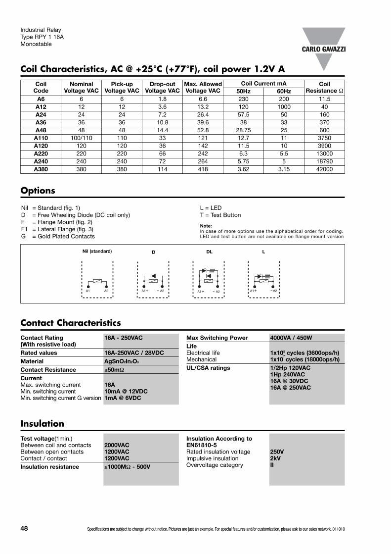
48 Specifications are subject to change without notice. Pictures are just an example. For special features and/or customization, please ask to our sales network. 011010
Contact CharacteristicsContact Rating 16A - 250VAC (With resistive load)Rated values 16A-250VAC / 28VDCMaterial AgSnO2In2O3
Contact Resistance ≤50mΩ
CurrentMax. switching current 16AMin. switching current 10mA @ 12VDCMin. switching current G version 1mA @ 6VDC
Max Switching Power 4000VA / 450WLifeElectrical life 1x10⁵ cycles (3600ops/h)Mechanical 1x10
7cycles (18000ops/h)
UL/CSA ratings 1/2Hp 120VAC1Hp 240VAC16A @ 30VDC16A @ 250VAC
Test voltage(1min.)Between coil and contacts 2000VACBetween open contacts 1200VACContact / contact 1200VACInsulation resistance ≥1000MΩ - 500V
InsulationInsulation According toEN61810-5Rated insulation voltage 250VImpulsive insulation 2kVOvervoltage category II
Coil Characteristics, AC @ +25°C (+77°F), coil power 1.2V A
Nil = Standard (fig. 1) L = LEDD = Free Wheeling Diode (DC coil only) T = Test ButtonF = Flange Mount (fig. 2)F1 = Lateral Flange (fig. 3)G = Gold Plated Contacts
Options
DLNil (standard) L
A2A1 -+ A2A1 -+A2A1 -+
D
Industrial Relay Type RPY 1 16AMonostable
CoilCode
NominalVoltage VAC
Pick-upVoltage VAC
Drop-outVoltage VAC
Max. AllowedVoltage VAC
Coil Current mA CoilResistance Ω50Hz 60Hz
A6 6 6 1.8 6.6 230 200 11.5A12 12 12 3.6 13.2 120 1000 40A24 24 24 7.2 26.4 57.5 50 160A36 36 36 10.8 39.6 38 33 370A48 48 48 14.4 52.8 28.75 25 600A110 100/110 110 33 121 12.7 11 3750A120 120 120 36 142 11.5 10 3900A220 220 220 66 242 6.3 5.5 13000A240 240 240 72 264 5.75 5 18790A380 380 380 114 418 3.62 3.15 42000
A2A1
Note:In case of more options use the alphabetical order for coding.LED and test button are not available on flange mount version

Specifications are subject to change without notice. Pictures are just an example. For special features and/or customization, please ask to our sales network. 011010 49
Dimensions mm/inches
Pin View mm/inches Wiring Diagram
+
-
14.2
/0.5
6”
10/0
.39”
8xØ2.5/0.10”3.6/0.14”
36/1.42”max 21.5/0.85” max
2/0.08”
38/1
.50”
max
43/1
.70”
max
38/1
.50”
max
28/1
.10”
max
5/0.
20”
7/0.28”
1
2
3
4
5
6
7
8
4.6/0.18”
4.95/0.19”
7.15/0.28”
General DataNominal coil power 0.9W DC – 1.2VA ACOperating time ≤20ms(at nominal voltage)Release time ≤20ms(at nominal voltage)Ambient temperature -25° to + 55°C (-13° to +131°F)Ambient humidity 35% to 85%
Vibration resistance 10 to 55Hz 1mm (0.04”)Shock resistanceFunctional 98m/s2 (10G)Termination Flanges (blades) 5mm (0.20”)Construction Dust cover IP 40Weight 35g (1.23oz)
BOTTOM VIEW RPY 1
Industrial Relay Type RPY 1 16AMonostable
43/1
.70”
max
5/0.
20”
3.5/0.14”
3.5/0.14”
0.5/
0.02
”
36/1.42”max
21.5/0.85” max
28/1
.10”
max
5/0.
20”
LATERAL VIEW BOTTOM VIEW
36/1.42”max
LATERAL VIEW BOTTOM VIEW
21.5/0.85” max
28/1
.10”
max
0.5/
0.02
”
LATERAL VIEW BOTTOM VIEW
7/0.28”
0.5/
0.02
”
STANDARD version (Fig.1) F version (Fig.2)
F1 version (Fig.3)
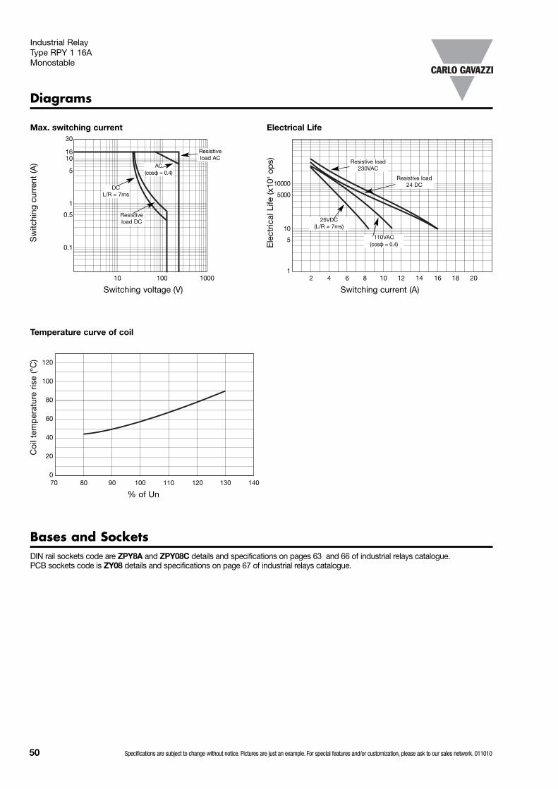
50 Specifications are subject to change without notice. Pictures are just an example. For special features and/or customization, please ask to our sales network. 011010
Diagrams
Bases and SocketsDIN rail sockets code are ZPY8A and ZPY08C details and specifications on pages 63 and 66 of industrial relays catalogue. PCB sockets code is ZY08 details and specifications on page 67 of industrial relays catalogue.
Sw
itchi
ng c
urre
nt (A
)
Max. switching current
Switching voltage (V)10 100 1000
30
1610
5
1
0.5
0.1 Ele
ctric
al L
ife (x
104
ops)
Electrical Life
Switching current (A)2 4 6 8 10 12 14 16 18 20
10000
5000
10
5
1
Coi
l tem
per
atur
e ris
e (°
C)
Temperature curve of coil
% of Un70 80 90 100 110 120 130 140
120
100
80
60
40
20
0
Resistiveload AC
AC(cosϕ = 0.4)
DC L/R = 7ms
Resistiveload DC
Resistive load 230VAC
Resistive load 24 DC
110VAC (cosϕ = 0.4)
25VDC (L/R = 7ms)
Industrial Relay Type RPY 1 16AMonostable
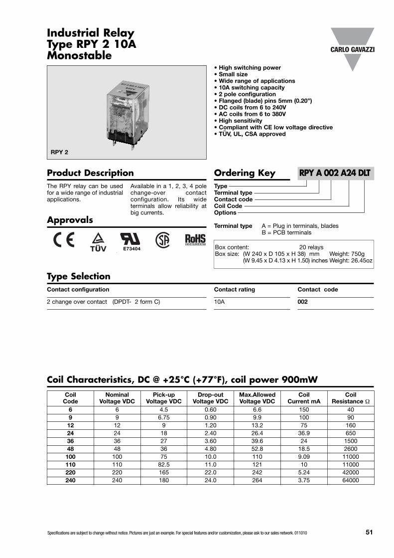
Specifications are subject to change without notice. Pictures are just an example. For special features and/or customization, please ask to our sales network. 011010 51
TypeTerminal typeContact codeCoil CodeOptions
Terminal type A = Plug in terminals, bladesB = PCB terminals
Contact configuration
2 change over contact (DPDT- 2 form C)
Approvals
Ordering Key
RPY 2
Product Description
• High switching power• Small size• Wide range of applications• 10A switching capacity• 2 pole configuration• Flanged (blade) pins 5mm (0.20”)• DC coils from 6 to 240V• AC coils from 6 to 380V• High sensitivity• Compliant with CE low voltage directive• TÜV, UL, CSA approved
RPY A 002 A24 DLT
Contact code
002
Type SelectionContact rating
10A
The RPY relay can be usedfor a wide range of industrialapplications.
Available in a 1, 2, 3, 4 polechange-over contactconfiguration. Its wideterminals allow reliability atbig currents.
Industrial RelayType RPY 2 10AMonostable
Coil Characteristics, DC @ +25°C (+77°F), coil power 900mWCoil
CodeNominal
Voltage VDCPick-up
Voltage VDCDrop-out
Voltage VDCMax.AllowedVoltage VDC
CoilCurrent mA
Coil Resistance Ω
6 6 4.5 0.60 6.6 150 409 9 6.75 0.90 9.9 100 9012 12 9 1.20 13.2 75 16024 24 18 2.40 26.4 36.9 65036 36 27 3.60 39.6 24 150048 48 36 4.80 52.8 18.5 2600100 100 75 10.0 110 9.09 11000110 110 82.5 11.0 121 10 11000220 220 165 22.0 242 5.24 42000240 240 180 24.0 264 3.75 64000
E73404 Box content: 20 relaysBox size: (W 240 x D 105 x H 38) mm Weight: 750g
(W 9.45 x D 4.13 x H 1.50) inches Weight: 26.45oz

52 Specifications are subject to change without notice. Pictures are just an example. For special features and/or customization, please ask to our sales network. 011010
Coil Characteristics, AC @ +25°C (+77°F), coil power 1.2VA
Contact CharacteristicsContact Rating 10A-250VAC(With resistive load)Rated values 10A-250VAC / 28VDCMaterial AgSnO2In2O3
Contact Resistance ≤50mΩ
CurrentMax. switching current 10AMin. switching current 10mA @ 12VDCMin. switching current G version 1mA @ 6VDC
Max Switching Power 2500VA / 280WLifeElectrical life 1x10⁵ cycles (3600ops/h)Mechanical 1x10⁷ cycles (18000ops/h)UL/CSA ratings 1/3Hp 120VAC
1/2Hp 240VAC10A @ 30VDC10A @ 250VAC
Test voltage(1min.)Between coil and contacts 2000VACBetween open contacts 1200VACContact / contact 1200VACInsulation resistance ≥1000MΩ - 500V
InsulationInsulation According toEN61810-5Rated insulation voltage 250VImpulsive insulation 2kVOvervoltage categor II
Nil = Standard (Fig.1) L = LEDD = Free Wheeling diode (DC coil only) T = Test ButtonF = Flange Mount (Fig.2)F1 = lateral flange (Fig.3)G = Gold Plated contacts
Options
DLNil (standard) L
A2A1 -+ A2A1 -+A2A1 -+
D
Industrial Relay Type RPY 2 10AMonostable
CoilCode
Nominal Voltage VAC
Pick-upVoltage VAC
Drop-outVoltage VAC
Max. AllowedVoltage VAC
Coil Current mA CoilResistance Ω50Hz 60Hz
A6 6 4.8 1.8 6.6 230 200 11.5A12 12 9.6 3.6 13.2 120 100 40A24 24 19.2 7.2 26.4 57.5 50 160A36 36 28.8 10.8 39.6 38 33 370A48 48 38.4 14.4 52.8 28.75 25 600A110 100/110 88 33.0 121 12.7 11 3750A120 120 96 36.0 142 11.5 10 3900A220 220 176 66.0 242 6.3 5.5 13000A240 240 192 72.0 264 5.75 5 18790A380 380 304 114 418 3.62 3.15 42000
A2A1
Note:In case of more options use the alphabetical order for coding.LED and test button are not available on flange mount version

Specifications are subject to change without notice. Pictures are just an example. For special features and/or customization, please ask to our sales network. 011010 53
Pin View mm/inches Wiring Diagram
+-
1
2
3
4
5
6
7
8
General DataNominal coil power 0.9W DC – 1.2VA ACOperating time ≤20ms(at nominal voltage)Release time ≤20ms(at nominal voltage)Ambient temperature -25°C +55°C (-13°F to +131°F)Ambient humidity 35% to 85%
Vibration resistance 10 to 55Hz 1mm (0.04”)Shock resistanceFunctional 98m/s2 (10G)Termination Flanges (blades) 5mm (0.20”)Construction Dust coverWeight 35g (1.23oz)
Industrial Relay Type RPY 2 10AMonostable
10/0
.39”
2.5/
0.10
”
7.15/0.28”
3.6/0.14”
4.95/0.19”
4.6/0.18”
8xØ2.5/0.10”
BOTTOM VIEW RPY 2
Dimensions mm/inches
36/1.42”max 21.5/0.85” max
2/0.08”
38/1
.50”
max
43/1
.70”
max
38/1
.50”
max
28/1
.10”
max
5/0.
20”
7/0.28”
43/1
.70”
max
5/0.
20”
3.5/0.14”
3.5/0.14”
0.5/
0.02
”
36/1.42”max
21.5/0.85” max
28/1
.10”
max
5/0.
20”
LATERAL VIEW BOTTOM VIEW
36/1.42”max
LATERAL VIEW BOTTOM VIEW
21.5/0.85” max
28/1
.10”
max
0.5/
0.02
”
LATERAL VIEW BOTTOM VIEW
7/0.28”
0.5/
0.02
”
STANDARD version (Fig.1) F version (Fig.2)
F1 version (Fig.3)

54 Specifications are subject to change without notice. Pictures are just an example. For special features and/or customization, please ask to our sales network. 011010
Diagrams
Sw
itchi
ng c
urre
nt (A
)
Max. switching current
Switching voltage (V)10 100 1000
30
10
5
1
0.5
0.1 Ele
ctric
al L
ife (x
104
ops)
Electrical Life
Switching current (A)2 4 6 8 10 12 14 16 18 20
10000
5000
10
5
1
Coi
l tem
per
atur
e ris
e (°
C)
Temperature curve of coil
% of Un70 80 90 100 110 120 130 140
120
100
80
60
40
20
0
Resistiveload AC
AC(cosϕ = 0.4)
DC L/R = 7ms
Resistiveload DC
Resistive load 230VAC
Resistive load 24 DC
110VAC (cosϕ = 0.4)
25VDC (L/R = 7ms)
Bases and SocketsDIN rail sockets code are ZPY8A and ZPY08C details and specifications on pages 63 and 66 of industrial relays catalogue. PCB sockets code is ZY08 details and specifications on page 67 of industrial relays catalogue.
Industrial Relay Type RPY 2 10AMonostable
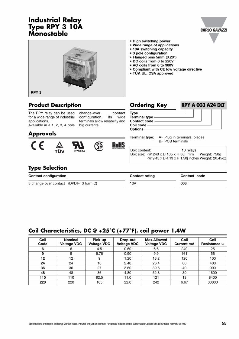
Specifications are subject to change without notice. Pictures are just an example. For special features and/or customization, please ask to our sales network. 011010 55
TypeTerminal typeContact codeCoil codeOptions
Terminal type: A= Plug in terminals, bladesB= PCB terminals
Contact configuration
3 change over contact (DPDT- 3 form C)
Approvals
Ordering Key
RPY 3
Product Description
• High switching power• Wide range of applications• 10A switching capacity• 3 pole configuration• Flanged pins 5mm (0.20”)• DC coils from 6 to 220V• AC coils from 6 to 380V• Compliant with CE low voltage directive• TÜV, UL, CSA approved
RPY A 003 A24 DLT
Contact code
003
Type SelectionContact rating
10A
The RPY relay can be usedfor a wide range of industrialapplications.Available in a 1, 2, 3, 4 pole
change-over contactconfiguration. Its wideterminals allow reliability andbig currents.
Industrial RelayType RPY 3 10AMonostable
Coil Characteristics, DC @ +25°C (+77°F), coil power 1.4WCoil
CodeNominal
Voltage VDCPick-up
Voltage VDCDrop-out
Voltage VDCMax.AllowedVoltage VDC
CoilCurrent mA
Coil Resistance Ω
6 6 4.5 0.60 6.6 240 259 9 6.75 0.90 9.9 161 5612 12 9 1.20 13.2 120 10024 24 18 2.40 26.4 60 40036 36 27 3.60 39.6 40 90048 48 36 4.80 52.8 30 1600110 110 82.5 11.0 121 13 8400220 220 165 22.0 242 6.67 33000
E73404 Box content: 10 relaysBox size: (W 240 x D 105 x H 38) mm Weight: 750g
(W 9.45 x D 4.13 x H 1.50) inches Weight: 26.45oz
56 Specifications are subject to change without notice. Pictures are just an example. For special features and/or customization, please ask to our sales network. 011010
Coil Characteristics, AC @ +25°C (77°F), coil power 2VA
Contact CharacteristicsContact Rating 10A - 250VAC(With resistive load)Usually rating 10A-250VAC / 28VDCMaterial AgSnO2In2O3
Contact Resistance ≤50mΩ
CurrentMax. switching current 10AMin. switching current 10mA @ 12VDCMin. switching current G version 1mA @ 6VDC
Max Switching Power 2500VA / 280WLifeElectrical life 1x10⁵ cycles (3600ops/h)Mechanical 1x10⁷ cycles (18000 ops/h)UL/CSA ratings 1/3Hp 120VAC
1/2Hp 240VAC10A @ 30VDC10A @ 250VAC
Test voltage (1min.)Between coil and contacts 2000VACBetween open contacts 1200VACContact / contact 1200VACInsulation resistance ≥1000MΩ - 500V
InsulationInsulation According to EN61810-5Rated insulation voltage 250VImpulsive insulation 2kVOvervoltage categor II
Nil = Standard (Fig.1) L = LEDD = Free Wheeling diode (DC coil only) T = Test ButtonF = Flange Mount (Fig.2)G = Gold Plated contacts
Options
DLNil (standard) L
A2A1 -+ A2A1 -+A2A1 -+
D
Industrial Relay Type RPY 3 10AMonostable
CoilCode
Nominal Voltage VAC
Pick-upVoltage VAC
Drop-outVoltage VAC
Max.AllowedVoltage VAC
Coil Current mA CoilResistance Ω50Hz 60Hz
A6 6 4.8 1.8 6.6 330 280 6.5A12 12 9.6 3.6 13.2 167 142 25.5A24 24 19.2 7.2 26.4 83 70 102A36 36 28.8 10.8 39.6 55 47 230A48 48 38.4 14.4 52.8 42 36 410A110 100/110 88 33.0 121 18 15 2300A120 120 96 36.0 142 17 14.5 2700A220 220 176 66.0 242 9 7.7 8600A240 240 192 72.0 264 8.3 7 10000A380 380 304 114 418 5.2 4.4 27500
A2A1
Note:In case of more options use the alphabetical order for coding.LED and test button are not available on flange mount version

Specifications are subject to change without notice. Pictures are just an example. For special features and/or customization, please ask to our sales network. 011010 57
Dimensions mm/inches
Pin View mm/inches Wiring Diagram
_ +
31.5
/1.2
4” m
ax
28/1
.10”
max
36/1.41” max
4.8/
0.19
”
7/0.27”
38.5
/1.5
1” ±
0.1
/0.0
03”
28/1
.10”
max
31.5
/1.2
4” m
ax
36/1.42” max
1 2 3
4 5 6
7 8 9
10 11
3.6/
0.14
”7.
15/0
.28”
13.1
5/0.
52”
3.6/0.14”
11xØ2.5/0.10”
General DataNominal coil power 1.4W DC – 1.2VA ACOperating time ≤20ms(at nominal voltage)Release time ≤20ms(at nominal voltage)Ambient temperature -25° to +55°C (-13° to +131°F)Ambient humidity 35% to 85%
Vibration resistance 10 to 55Hz 1mm (0.04”)Shock resistanceFunctional 98m/s2 (10G)Termination Flanges (blades) 5mm (0.20”)Construction Dust coverWeight 50g (1.76oz)
Industrial Relay Type RPY 3 10AMonostable
7/0.28”
43/1
.70”
max
4.6/
0.18
”
BOTTOM VIEW RPY 3
LATERAL VIEW REAR VIEW BOTTOM VIEW
STANDARD version (Fig.1)
F version (Fig.2)
5.0/
0.20
LATERAL VIEW REAR VIEW BOTTOM VIEW
28/1
.10”
max
2/0.08”3.5/0.14”
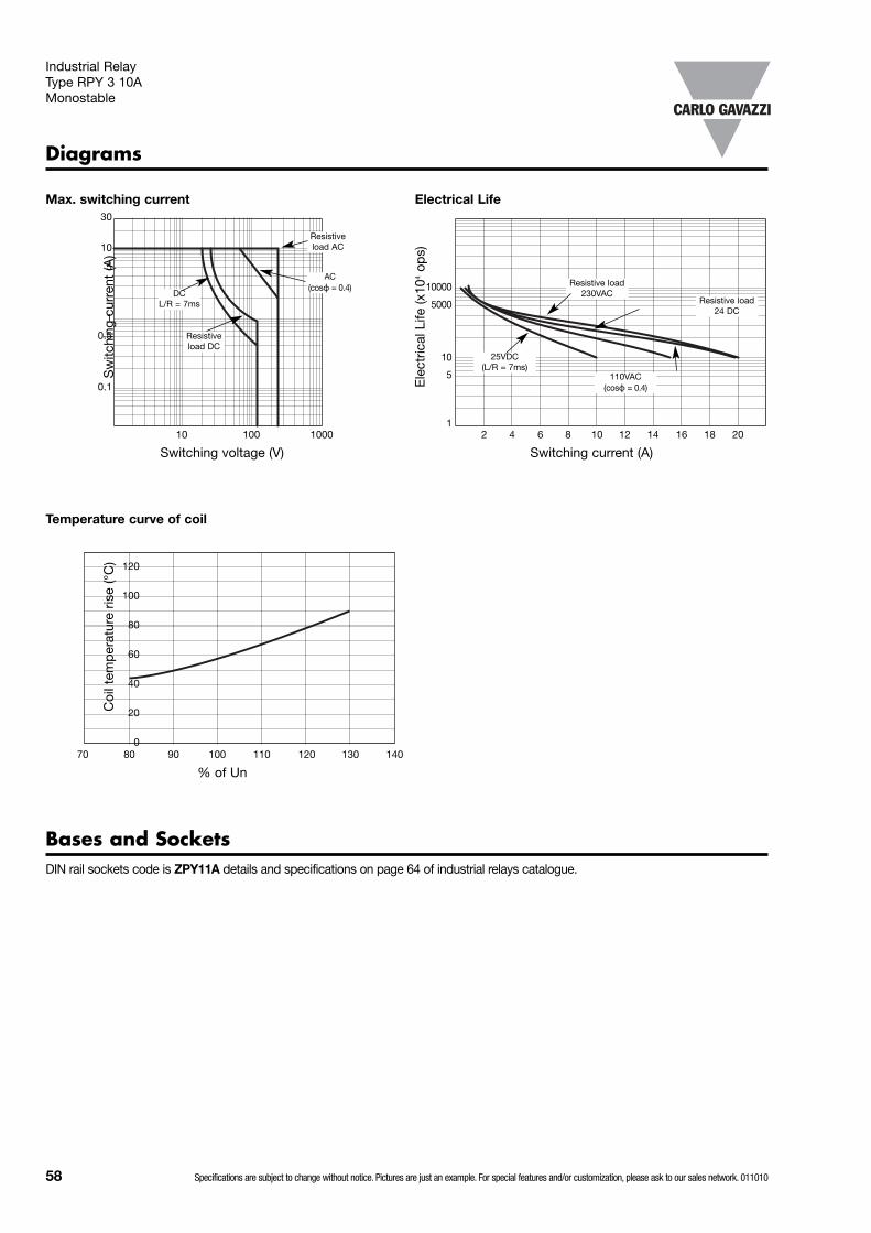
58 Specifications are subject to change without notice. Pictures are just an example. For special features and/or customization, please ask to our sales network. 011010
Bases and SocketsDIN rail sockets code is ZPY11A details and specifications on page 64 of industrial relays catalogue.
Diagrams
Sw
itchi
ng c
urre
nt (A
)
Max. switching current
Switching voltage (V)10 100 1000
30
10
5
1
0.5
0.1 Ele
ctric
al L
ife (x
104
ops)
Electrical Life
Switching current (A)2 4 6 8 10 12 14 16 18 20
10000
5000
10
5
1
Coi
l tem
per
atur
e ris
e (°
C)
Temperature curve of coil
% of Un70 80 90 100 110 120 130 140
120
100
80
60
40
20
0
Resistiveload AC
AC(cosϕ = 0.4)
DC L/R = 7ms
Resistiveload DC
Resistive load 230VAC
Resistive load 24 DC
110VAC (cosϕ = 0.4)
25VDC (L/R = 7ms)
Industrial Relay Type RPY 3 10AMonostable
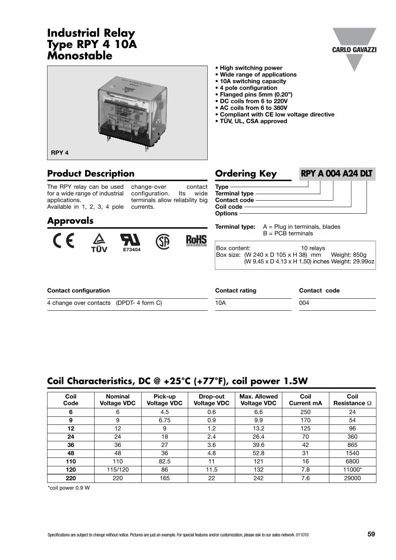
Specifications are subject to change without notice. Pictures are just an example. For special features and/or customization, please ask to our sales network. 011010 59
TypeTerminal typeContact codeCoil codeOptions
Terminal type: A = Plug in terminals, bladesB = PCB terminals
Contact configuration
4 change over contacts (DPDT- 4 form C)
Approvals
Ordering Key
RPY 4
Product Description
• High switching power• Wide range of applications• 10A switching capacity• 4 pole configuration• Flanged pins 5mm (0.20”)• DC coils from 6 to 220V• AC coils from 6 to 380V• Compliant with CE low voltage directive• TÜV, UL, CSA approved
RPY A 004 A24 DLT
Contact code
004
Contact rating
10A
The RPY relay can be usedfor a wide range of industrialapplications.Available in 1, 2, 3, 4 pole
change-over contactconfiguration. Its wideterminals allow reliability bigcurrents.
Industrial RelayType RPY 4 10AMonostable
Coil Characteristics, DC @ +25°C (+77°F), coil power 1.5W
CoilCode
Nominal Voltage VDC
Pick-upVoltage VDC
Drop-outVoltage VDC
Max. AllowedVoltage VDC
CoilCurrent mA
Coil Resistance Ω
6 6 4.5 0.6 6.6 250 249 9 6.75 0.9 9.9 170 5412 12 9 1.2 13.2 125 9624 24 18 2.4 26.4 70 36036 36 27 3.6 39.6 42 86548 48 36 4.8 52.8 31 1540110 110 82.5 11 121 16 6800120 115/120 86 11.5 132 7.8 11000*220 220 165 22 242 7.6 29000
E73404 Box content: 10 relaysBox size: (W 240 x D 105 x H 38) mm Weight: 850g
(W 9.45 x D 4.13 x H 1.50) inches Weight: 29.99oz
*coil power 0.9 W
60 Specifications are subject to change without notice. Pictures are just an example. For special features and/or customization, please ask to our sales network. 011010
Contact CharacteristicsContact Rating 10A – 250VAC(With resistive load)Usually rating 10A-250VAC / 28VDCMaterial AgSnO2In2O3
Contact Resistance ≤50mΩ
CurrentMax. switching current 10AMin. switching current 10mA @ 12VDCMin. switching current G version 1mA @ 6VDC
Max Switching Power 2500VA / 280WLifeElectrical life 1x10⁵ cycles (3600ops/h)Mechanical 1x10⁷ cycles (18000ops/h)UL/CSA ratings 1/3Hp 120VAC
1/2Hp 240VAC10A @ 30VDC10A @ 250VAC
Test voltage(1min.)Between coil and contacts 2000VACBetween open contacts 1200VACContact / contact 1200VACInsulation resistance ≥1000MΩ - 500V
InsulationInsulation According toEN61810-5Rated insulation voltage 250VImpulsive insulation 2kVOvervoltage categor II
Coil Characteristics, AC @ +25°C (+77°F), coil power 2.5VA
Nil = Standard (Fig.1) L = LEDD = Free Wheeling diode (DC coil only) T = Test ButtonF = Flange Mount (Fig.2)G = Gold Plated contacts
Options
DLNil (standard) L
A2A1 -+ A2A1 -+A2A1 -+
/D
Industrial Relay Type RPY 4 10AMonostable
Coil Code
NominalVoltage VAC
Pick-upVoltage VAC
Drop-outVoltage VAC
Max. AllowedVoltage VAC
Coil Current mA CoilResistance Ω50Hz 60Hz
A6 6 4.8 1.8 6.6 420 360 5A12 12 9.6 3.6 13.2 210 180 20A24 24 19.2 7.2 26.4 100 85 80A36 36 28.8 10.8 39.6 70 60 180A48 48 38.4 14.4 52.8 52 44 320A110 100/110 88.0 30.0 121.0 25/23 21/19.5 1680A120 120 96.0 36.0 142.0 20 17 2000A220 220 176 66.0 242.0 12 10 6700A240 240 192 72.0 264.0 10 8.5 8000A380 380 304 114.0 418.0 6.5 5.5 29000
A2A1
Note:In case of more options use the alphabetical order for coding.LED and test button are not available on flange mount version

Specifications are subject to change without notice. Pictures are just an example. For special features and/or customization, please ask to our sales network. 011010 61
Dimensions mm/inches
Pin View mm/inches Wiring Diagram
5/0.20”
5/0.20”
7/0.27”
36/1.42”
28/1
.10”
max
41.5
/1.6
3” m
ax
43/1
.69”
40/1.57”
3.5/0.14”
10/0.39”
3.6/0.14”
4.6/0.18”
4.95/0.19”
7.15/0.28”
14xØ2.5/0.1030/1.18”
PCB version: pin dimension 1.5x0.5mm (0.05”x0.02”)
1 2 3 4
5 6 7 8
9 10 11 1213 14
- +
Industrial Relay Type RPY 4 10AMonostable
10/0.39”10/0.39”BOTTOM VIEW RPY 4
General DataNominal coil power 1.5W DC – 2.5VA ACOperating time ≤20ms(at nominal voltage)Release time ≤20ms(at nominal voltage)Ambient temperature -25° to +55°C (-13° to +131°F)Ambient humidity 35% to 85%
Vibration resistance 10 to 55Hz 1mm (0.04”)Shock resistanceFunctional 98m/s2 (10G)Termination Flanges (blades) 5mm (0.20”)Construction Dust coverWeight 65g (2.29oz)
LATERAL VIEW REAR VIEW BOTTOM VIEW
STANDARD version (Fig.1)
LATERAL VIEW REAR VIEW BOTTOM VIEW
F version (Fig.2)
36/1.42”
41.5
/1.6
3” m
ax
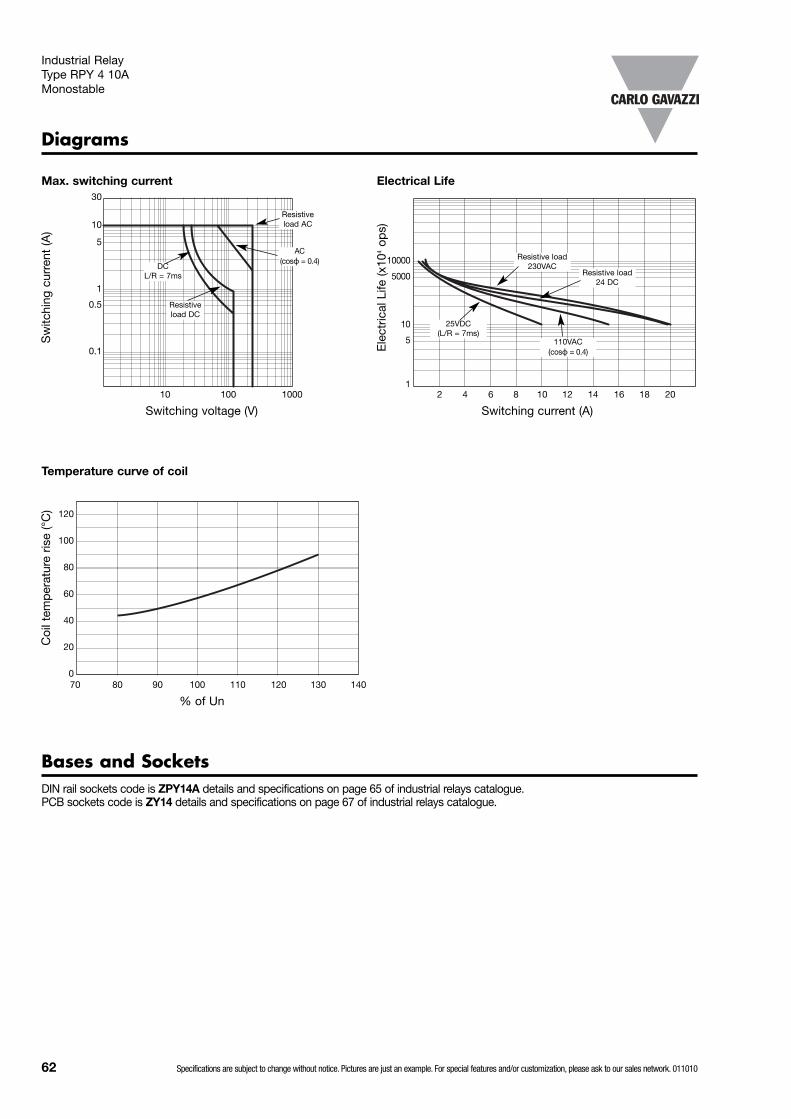
62 Specifications are subject to change without notice. Pictures are just an example. For special features and/or customization, please ask to our sales network. 011010
Industrial Relay Type RPY 4 10AMonostable
Bases and SocketsDIN rail sockets code is ZPY14A details and specifications on page 65 of industrial relays catalogue. PCB sockets code is ZY14 details and specifications on page 67 of industrial relays catalogue.
Diagrams
Sw
itchi
ng c
urre
nt (A
)
Max. switching current
Switching voltage (V)10 100 1000
30
10
5
1
0.5
0.1 Ele
ctric
al L
ife (x
104
ops)
Electrical Life
Switching current (A)2 4 6 8 10 12 14 16 18 20
10000
5000
10
5
1
Coi
l tem
per
atur
e ris
e (°
C)
Temperature curve of coil
% of Un70 80 90 100 110 120 130 140
120
100
80
60
40
20
0
Resistiveload AC
AC(cosϕ = 0.4)
DC L/R = 7ms
Resistiveload DC
Resistive load 230VAC
Resistive load 24 DC
110VAC (cosϕ = 0.4)
25VDC (L/R = 7ms)
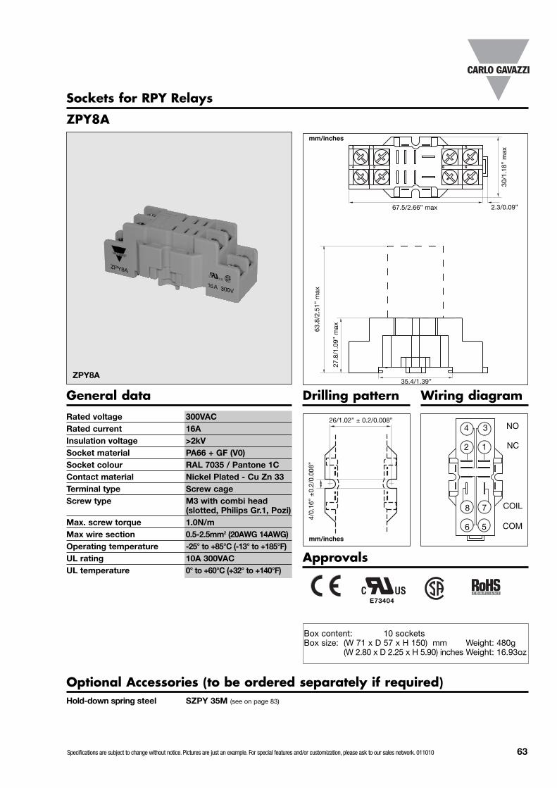
Specifications are subject to change without notice. Pictures are just an example. For special features and/or customization, please ask to our sales network. 011010 63
Sockets for RPY Relays
ZPY8A
General dataRated voltage 300VACRated current 16AInsulation voltage >2kVSocket material PA66 + GF (V0)Socket colour RAL 7035 / Pantone 1CContact material Nickel Plated - Cu Zn 33Terminal type Screw cageScrew type M3 with combi head
(slotted, Philips Gr.1, Pozi)Max. screw torque 1.0N/mMax wire section 0.5-2.5mm2 (20AWG 14AWG) Operating temperature -25° to +85°C (-13° to +185°F)UL rating 10A 300VACUL temperature 0° to +60°C (+32° to +140°F)
3 1
4 2
7 5
8 6
30/1
.18”
max
67.5/2.66” max
27.8
/1.0
9” m
ax
4
2
8
6
3
1
7
5
26/1.02” ± 0.2/0.008”
4/0.
16”
±0.
2/0.
008”
Approvals
35.4/1.39”ZPY8A
NO
COM
COIL
NC
mm/inches
mm/inches
2.3/0.09”
E73404
Wiring diagramDrilling pattern
Optional Accessories (to be ordered separately if required)Hold-down spring steel SZPY 35M (see on page 83)
Box content: 10 socketsBox size: (W 71 x D 57 x H 150) mm Weight: 480g
(W 2.80 x D 2.25 x H 5.90) inches Weight: 16.93oz
63.8
/2.5
1” m
ax
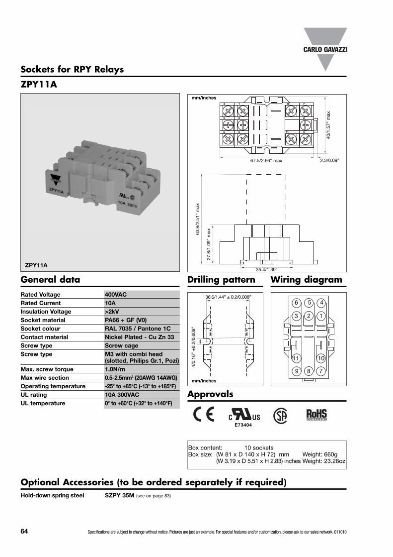
64 Specifications are subject to change without notice. Pictures are just an example. For special features and/or customization, please ask to our sales network. 011010
Sockets for RPY Relays
ZPY11A
General dataRated Voltage 400VACRated Current 10AInsulation Voltage >2kVSocket material PA66 + GF (V0)Socket colour RAL 7035 / Pantone 1CContact material Nickel Plated - Cu Zn 33Screw type Screw cageScrew type M3 with combi head
(slotted, Philips Gr.1, Pozi)Max. screw torque 1.0N/mMax wire section 0.5-2.5mm2 (20AWG 14AWG) Operating temperature -25° to +85°C (-13° to +185°F)UL rating 10A 300VACUL temperature 0° to +60°C (+32° to +140°F)
4 1
5 2
10 7
8
40/1
.57”
max
67.5/2.66” max
27.8
/1.0
9” m
ax
6
3
11
9
5
2
8
36.6/1.44” ± 0.2/0.008”
4/0.
16”
±0.
2/0.
008”
Approvals
35.4/1.39”ZPY11A
mm/inches
mm/inches
2.3/0.09”
E73404
Wiring diagramDrilling pattern
Optional Accessories (to be ordered separately if required)Hold-down spring steel SZPY 35M (see on page 83)
Box content: 10 socketsBox size: (W 81 x D 140 x H 72) mm Weight: 660g
(W 3.19 x D 5.51 x H 2.83) inches Weight: 23.28oz
63.8
/2.5
1” m
ax
4
1
10
7
6 3 11 9
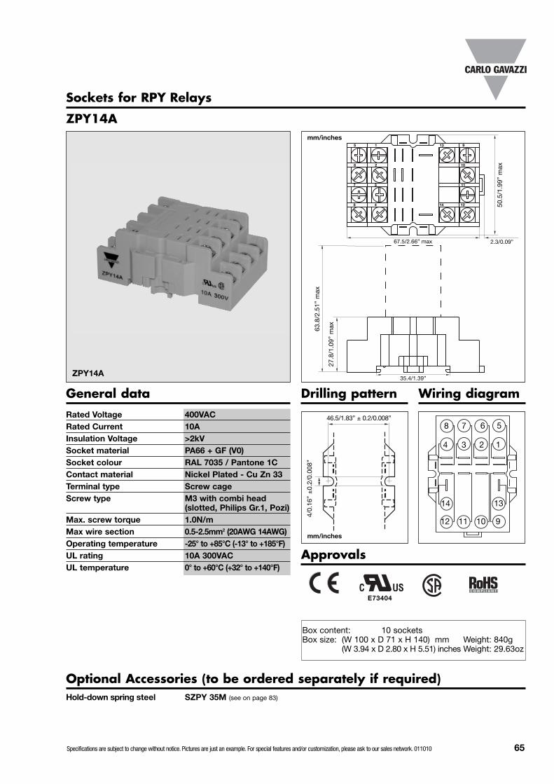
Specifications are subject to change without notice. Pictures are just an example. For special features and/or customization, please ask to our sales network. 011010 65
Sockets for RPY Relays
ZPY14A
General dataRated Voltage 400VACRated Current 10AInsulation Voltage >2kVSocket material PA66 + GF (V0)Socket colour RAL 7035 / Pantone 1CContact material Nickel Plated - Cu Zn 33Terminal type Screw cageScrew type M3 with combi head
(slotted, Philips Gr.1, Pozi)Max. screw torque 1.0N/mMax wire section 0.5-2.5mm2 (20AWG 14AWG) Operating temperature -25° to +85°C (-13° to +185°F)UL rating 10A 300VACUL temperature 0° to +60°C (+32° to +140°F)
5 1
6 2
13 9
11
10
50.5
/1.9
9” m
ax
67.5/2.66” max
27.8
/1.0
9” m
ax
7
3
6
2
10
46.5/1.83” ± 0.2/0.008”
4/0.
16”
±0.
2/0.
008”
Approvals
35.4/1.39”ZPY14A
mm/inches
mm/inches
2.3/0.09”
E73404
Wiring diagramDrilling pattern
Optional Accessories (to be ordered separately if required)Hold-down spring steel SZPY 35M (see on page 83)
Box content: 10 socketsBox size: (W 100 x D 71 x H 140) mm Weight: 840g
(W 3.94 x D 2.80 x H 5.51) inches Weight: 29.63oz
63.8
/2.5
1” m
ax
5
1
13
9
8
4
14
1112
8 4 14 12
7 3
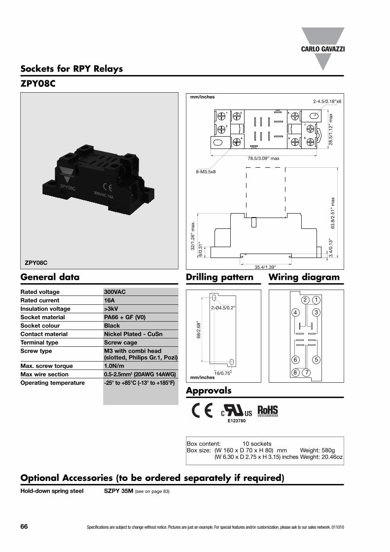
66 Specifications are subject to change without notice. Pictures are just an example. For special features and/or customization, please ask to our sales network. 011010
Sockets for RPY Relays
ZPY08C
General dataRated voltage 300VACRated current 16AInsulation voltage >3kVSocket material PA66 + GF (V0)Socket colour BlackContact material Nickel Plated - CuSnTerminal type Screw cageScrew type M3 with combi head
(slotted, Philips Gr.1, Pozi)Max. screw torque 1.0N/mMax wire section 0.5-2.5mm2 (20AWG 14AWG) Operating temperature -25° to +85°C (-13° to +185°F)
1 3
2
4
28.5
/1.1
2” m
ax
78.5/3.09” max
32/1
.26”
max
.
2
4
6
8
1
3
5
7
2-Ø4.5/0.2”
68/2
.68”
Approvals
35.4/1.39”ZPY08C
mm/inches
mm/inches
Wiring diagramDrilling pattern
Optional Accessories (to be ordered separately if required)Hold-down spring steel SZPY 35M (see on page 83)
Box content: 10 socketsBox size: (W 160 x D 70 x H 80) mm Weight: 580g
(W 6.30 x D 2.75 x H 3.15) inches Weight: 20.46oz
63.8
/2.5
1” m
ax
8/0.
31”
3.4/
0.13
”
19/0.75”
7
5
86
8-M3.5x8
2-4.5/0.18”x6
E123780

Specifications are subject to change without notice. Pictures are just an example. For special features and/or customization, please ask to our sales network. 011010 67
Sockets for RPY Relays
ZY 08
General dataRated voltage 300VRated current 16AInsulation voltage 2kVOperating temperature -25° to +85°C (-13° to +185°F)Socket material ABSSocket colour RAL 7035 / Pantone 1CContact material Copper tin plated CuSn6
16/0
.63”
29/1.14”
21/0
.83”
Sockets for RPY Relays
ZY 14
General dataRated voltage 300VRated current 16AInsulation voltage 2kVOperating temperature -25° to +85°C (-13° to +185°F)Socket material ABSSocket colour RAL 7035 / Pantone 1CContact material Copper tin plated CuSn6
1 4
5 8
9 12
13 14
16/0.63”
29/1
.14”
41/1.61”
2
6
10
3
7
11
1
2
34
5
6
7
8
ZY 14
ZY 08
mm/inches
mm/inches
Box content: 10 socketsBox size: (W 125 x D 30 x H 25) mm Weight: 100g
(W 4.93 D 1.18 x H 0.98) inches Weight: 3.53oz
Box content: 10 socketsBox size: (W 125 x D 45 x H 30) mm Weight: 180g
(W 4.93 D 1.77 x H 1.18) inches Weight: 6.35oz
Approvals
Approvals
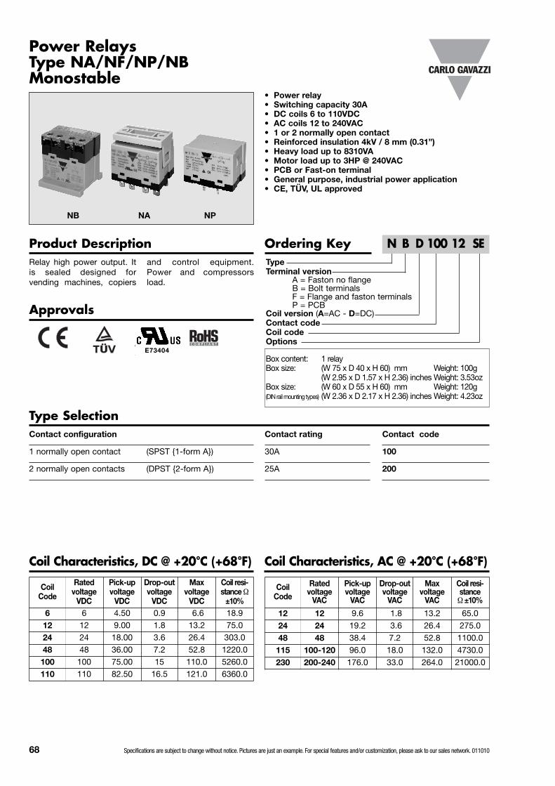
68 Specifications are subject to change without notice. Pictures are just an example. For special features and/or customization, please ask to our sales network. 011010
TypeTerminal version
A = Faston no flangeB = Bolt terminalsF = Flange and faston terminalsP = PCB
Coil version (A=AC - D=DC)Contact codeCoil codeOptions
Approvals
Ordering Key Product Description
Power Relays Type NA/NF/NP/NBMonostable
Relay high power output. Itis sealed designed forvending machines, copiers
and control equipment.Power and compressorsload.
• Power relay • Switching capacity 30A • DC coils 6 to 110VDC• AC coils 12 to 240VAC• 1 or 2 normally open contact• Reinforced insulation 4kV / 8 mm (0.31”) • Heavy load up to 8310VA• Motor load up to 3HP @ 240VAC• PCB or Fast-on terminal• General purpose, industrial power application• CE, TÜV, UL approved
N B D 100 12 SE
Contact code
100
200
Contact configuration
1 normally open contact (SPST {1-form A})
2 normally open contacts (DPST {2-form A})
Contact rating
30A
25A
Type Selection
Coil Characteristics, DC @ +20°C (+68°F) Coil Characteristics, AC @ +20°C (+68°F)
NB NA NP
Coil Code
Rated voltage
VDC
Pick-up voltage
VDC
Drop-outvoltage
VDC
Maxvoltage
VDC
Coil resi-stance Ω
±10%6 6 4.50 0.9 6.6 18.9
12 12 9.00 1.8 13.2 75.0
24 24 18.00 3.6 26.4 303.0
48 48 36.00 7.2 52.8 1220.0
100 100 75.00 15 110.0 5260.0
110 110 82.50 16.5 121.0 6360.0
Coil Code
Rated voltage
VAC
Pick-up voltage
VAC
Drop-out voltage
VAC
Max voltage
VAC
Coil resi-stance
Ω ±10%
12 12 9.6 1.8 13.2 65.0
24 24 19.2 3.6 26.4 275.0
48 48 38.4 7.2 52.8 1100.0
115 100-120 96.0 18.0 132.0 4730.0
230 200-240 176.0 33.0 264.0 21000.0
E73404Box content: 1 relayBox size: (W 75 x D 40 x H 60) mm Weight: 100g
(W 2.95 x D 1.57 x H 2.36) inches Weight: 3.53ozBox size: (W 60 x D 55 x H 60) mm Weight: 120g(DIN rail mounting types) (W 2.36 x D 2.17 x H 2.36) inches Weight: 4.23oz

Specifications are subject to change without notice. Pictures are just an example. For special features and/or customization, please ask to our sales network. 011010 69
Power Relays Type NA/NF/NPMonostable
General DataVibration resistance 1.5mm p.p. 10 to 55HzShock resist. Functional 98m/s2 (malfunction) 10G
Distructive 980m/s2 (mechanical) 100GHumidity 98% +40°C (+104°F)Weight 90 to 120g (3.17 to 4.23oz)Construction Dust cover Nominal coil power AC version 2.5VA
DC version 1.9WOperate time at nom. voltage 30msRelease time at nom. voltage 30msAmbient temperature -55° to +70°C (-67° to +158°F)Temperature rise +50°C (+122°F) max.Vibration resistance 1.5mm (0.06”) p.p. 10 to 50Hz
InsulationTest voltage (1 min.)Open contacts 2000VACContacts different polarity 2000VACContacts/coil 4000VACSurge voltageContacts/coil 10000VACInitial insulation resistance@ 500VDC 100MΩ
Contact CharacteristicsMaterial Silver alloyInitial contact resistance 100mΩ max. (1A-24VDC)CurrentMax. switching current 30A 25AMax. switching power 8310VA/840W 6925VA/700WVoltageMax. switching voltage 277VAC / 28VDC max.LifeElectrical life 1 x 10⁵ ops (1800 ops/h)Mechanical life 1 x 10⁶ ops (1800 ops/h)
100 200Rating 30A 25AUL rating 1.5HP / 120VAC
3HP / 240VAC30A / 277VAC
TV 10Contact rating 30A/277VAC 25A/277VACwith resistive load 30A/28VDC 25A/28VDCwith motor load @120VAC 1.5HP
@240VAC 3HP
Options
For NA relays
Nil = Standard with mounting clip (i.e. fig.1)T = Test button and mechanical indicator (i.e. fig.1)
For NF relays
Nil = Standard top flange mounting (i.e. fig.2)D = With DIN rail mounting (i.e. fig.3)T = Test button and mechanical indicator (i.e. fig.2)
Note: If not listed above option is not available.
For NP relays
Nil = Standard without mounting clip (i.e. fig.4)SE = With mounting clip (i.e. fig.5)
For NB relays (Protection cover for terminals always included)
DE = With DIN rail mounting (i.e. fig.8)SE = With mounting clip (i.e. fig.6)DL = With DIN rail mounting and LED indication (i.e. fig.8) FL = Top flange mounting and LED indication (i.e. fig.7)SL = With mounting clip and LED indication (i.e. fig.6)
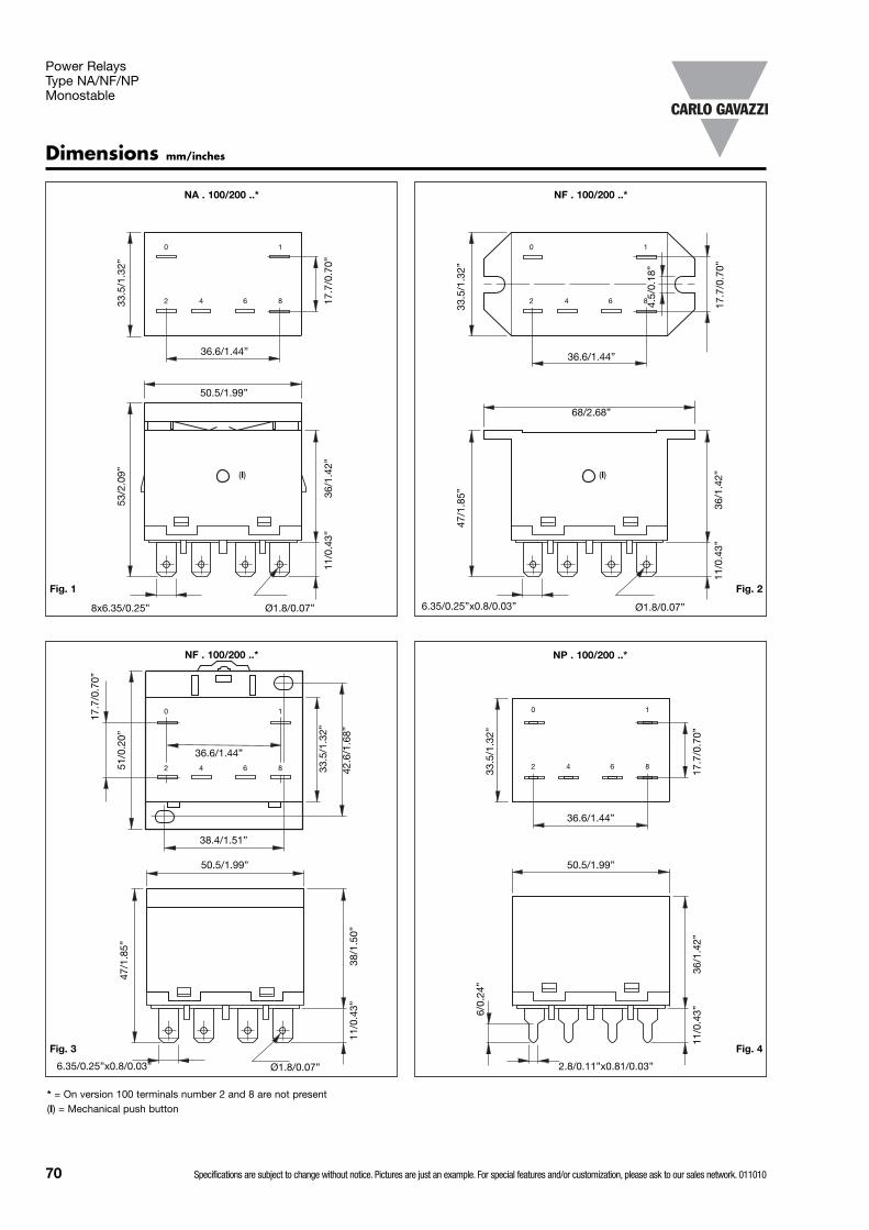
70 Specifications are subject to change without notice. Pictures are just an example. For special features and/or customization, please ask to our sales network. 011010
Dimensions mm/inches
NP . 100/200 ..*
NF . 100/200 ..*NA . 100/200 ..*
8x6.35/0.25”
53/2
.09”
50.5/1.99”
36.6/1.44”
36/1
.42”
Ø1.8/0.07”
17.7
/0.7
0”
33.5
/1.3
2”
11/0
.43”
6.35/0.25”x0.8/0.03”
47/1
.85”
68/2.68”
36.6/1.44”
36/1
.42”
Ø1.8/0.07”
17.7
/0.7
0”
33.5
/1.3
2”
11/0
.43”
4.5/
0.18
”
50.5/1.99”
36.6/1.44”
36/1
.42”
17.7
/0.7
0”
33.5
/1.3
2”
11/0
.43”
2.8/0.11”x0.81/0.03”
6/0.
24”
Power Relays Type NA/NF/NPMonostable
NF . 100/200 ..*
6.35/0.25”x0.8/0.03”
47/1
.85”
38/1
.50”
Ø1.8/0.07”
11/0
.43”
51/0
.20”
33.5
/1.3
2”
42.6
/1.6
8”
38.4/1.51”
36.6/1.44”
17.7
/0.7
0”
50.5/1.99”
Fig. 1 Fig. 2
Fig. 3 Fig. 4
0 1
2 84 6
0 1
2 84 6
0 1
2 84 6
0 1
2 84 6
(I)
* = On version 100 terminals number 2 and 8 are not present(I) = Mechanical push button
(I)

Specifications are subject to change without notice. Pictures are just an example. For special features and/or customization, please ask to our sales network. 011010 71
Power Relays Type NA/NF/NPMonostable
NB . 100/200 ..*
50.5/1.99”
M4
49/1
.93”
max
51/0
.20”
33.5
/1.3
2”
42.6
/1.6
8”
38.4/1.51”
54/2
.13”
max
NB. 100/200 ..*
59/2
.32”
50.5/1.99”
33.5
/1.3
2”
M4
50/1
.97”
NB . 100/200 ..*
M4
51.5
/2.0
3” m
ax
17.7
/0.7
0”
33.5
/1.3
2”
68/2.68”
Fig. 6
Fig. 7 Fig. 8
0 1
2 84 6
0 1
2 84 6
0 1
2 84 6
(II)
* = On version 100 terminals number 2 and 8 are not present(I) = Mechanical push button(II) = LED indication
NP . 100/200 ..*
50.5/1.99”
36.6/1.44”
36/1
.42”
17.7
/0.7
0”
33.5
/1.3
2”
11/0
.43”
2.8/0.11”x0.81/0.03”
6/0.
24”
Fig. 5
0 1
2 84 6
53/2
.09”
(II)
(II)

72 Specifications are subject to change without notice. Pictures are just an example. For special features and/or customization, please ask to our sales network. 011010
1H
2H
30
50
20
10
7
5
3
1
10 30 50 70 100 300 500
Nominal voltage (V)
Sw
itchi
ng c
urre
nt (A
)
Pin View mm/inches
SOLDER SIDENA/NF/NP/NB . 100 .. NA/NF/NP/NB . 200 ..
SOLDER SIDENP . 100 .. NP . 200 ..
Wiring Diagram
Diagrams
Contact current
Op
erat
ions
(100
00)
1 Contact rating 2 Life endurance
8.6/0.34”
14.4
/0.5
7”
17.7/0.70”
3.3/
0.13
”x 1
.1/0
.04”
8.6/0.34”
36.6
/1.4
4”
17.7/0.70”
3.3/
0.13
”x 1
.1/0
.04”
Panel mounting clip
Drilling patterns mm/inches
40/1
.57” 2x
Ø4.
5/0.
18”
Panel top flange mounting Panel/DIN rail mounting
60/1
.57”
42.6
/2.3
6”
38.4/1.51”
0
1
2
8
4
6
0
1
4
6
0
1
2
8
4
6
0
1
4
6
LED
op
tion
LED
op
tion
Power Relays Type NA/NF/NPMonostable

Specifications are subject to change without notice. Pictures are just an example. For special features and/or customization, please ask to our sales network. 011010 73
TypeTerminal version(S30= Soldering - F30= Fast-on)Coil version (A=AC - D=DC)Contact codeCoil code
Ordering Key Product Description
Power Relays Type CS30/CF30Monostable
Relay high power output. It is sealed designed for
vending machines, andcompressors load.
• Compressor control relay • Switching capacity 30A • DC coils 6 to 48VDC• AC coils 24 to 277VAC• 2 normally open contacts, 2 change over contacts• Reinforced insulation 4kV / 8mm (0.31”)• Meets class F construction• PCB or Fast-on terminal• General purpose, power loads• Standard as sealed• CE, UL approved
C S30 A 002 012
Coil Characteristics, DC @ +20°C (+68°F) Coil Characteristics, AC @ +20°C (+68°F) 50/60Hz
Contact Characteristics200 002(NO) (NO) (NC)
UL rating 30A - 277VAC 30A - 277VAC 3A - 277VAC2.5HP - 240VAC 2.5HP - 240VAC 2.5HP - 240VAC1HP - 120VAC 1HP - 120VAC 1HP - 120VAC
TV 10 110LRA / 25.3FLA -VDE rating 30A - 250VAC 30A - 250VAC 3A - 250VACContact rating 30A - 277VAC 30A - 277VAC 3A - 277VACMaterial AgSnO2 AgSnO2
Initial contact resistance 50mΩ max. (1A-6VDC) 50mΩ max. (1A-6VDC)CurrentMax. switching current 30A 30AMax. switching power 8310VA 8310VAVoltageMax. switching voltage 30VDC / 277VAC 30VDC / 277VACLifeElectrical life 1 x 10⁵ops/min. 1 x 10⁵ops/min.Mechanical life 5 x 10⁶ops/min. 5 x 10⁶ops/min.
Contact code
200
002
Contact configuration
2 normally open contact (DPST {2-form A})
2 change over contact (DPDT {2-form C})
Contact rating
30A
30A
Type Selection
CS30 CF30
ApprovalsThe approvals stated arenot generally applicableto all relay versions of aparticular type.
Coil Code
Rated voltage
VDC
Pick-up voltage
VDC
Drop-out voltage
VDC
Max.Allowable
voltage DC
Coil resistance Ω ±10%
005 5 3.8 0.5 5.5 15.3006 6 4.5 0.6 6.6 22012 12 9.0 1.2 13.2 86024 24 18.0 2.4 26.4 350048 48 36.0 4.8 52.8 1390110 110 83 11 121 7255
Coil Code
Rated voltage
VAC
Pick-up voltage
VAC
Drop-out voltage
VAC
Max.Allowablevoltage AC
Coil resistance Ω ±10%
024 24 19.2 4.8 26.4 39120 120 96.0 24.0 132.0 950
208B1 208 166.4 41.6 228.8 28412202 220 175 44.0 242.0 3800240 240 192.0 48.0 264.0 3800277 277 211.6 55.4 304.7 5485
E60304
1 Only 60Hz2 Only 50Hz
Box content: 20 relaysBox size: (W 290 x D 240 x H 40) mm Weight: 2.000g
(W 11.42 x D 9.45 x H 1.57) inches Weight: 70.55oz
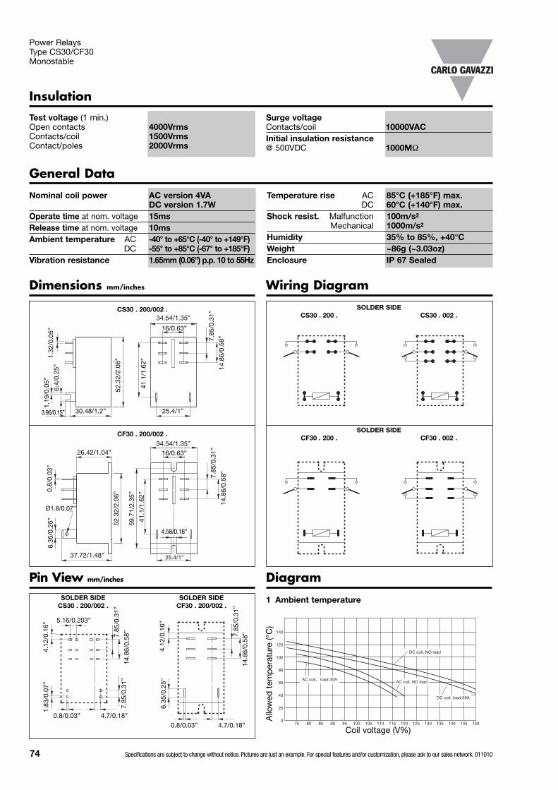
AC coil, load 30A AC coil, NO load
DC coil, load 30A
DC coil, NO load
140
100
120
60
80
40
20
075 80 85 90 95 100 105 110 115 120 125 130 135 140 145 150
Power Relays Type CS30/CF30Monostable
General Data
Temperature rise AC 85°C (+185°F) max.DC 60°C (+140°F) max.
Shock resist. Malfunction 100m/s2
Mechanical 1000m/s2
Humidity 35% to 85%, +40°CWeight ~86g (~3.03oz)Enclosure IP 67 Sealed
Nominal coil power AC version 4VA DC version 1.7W
Operate time at nom. voltage 15msRelease time at nom. voltage 10msAmbient temperature AC -40° to +65°C (-40° to +149°F)
DC -55° to +85°C (-67° to +185°F)Vibration resistance 1.65mm (0.06”) p.p. 10 to 55Hz
Diagram
1 Ambient temperature
InsulationTest voltage (1 min.)Open contacts 4000VrmsContacts/coil 1500VrmsContact/poles 2000Vrms
Surge voltageContacts/coil 10000VACInitial insulation resistance@ 500VDC 1000MΩ
SOLDER SIDECS30 . 200/002 .
SOLDER SIDECS30 . 200 . CS30 . 002 .
SOLDER SIDECF30 . 200 . CF30 . 002 .
Dimensions mm/inches
Pin View mm/inches
Wiring Diagram
CS30 . 200/002 .
CF30 . 200/002 .
SOLDER SIDECF30 . 200/002 .
Coil voltage (V%)
Allo
wed
tem
per
atur
e (°
C)
30.48/1.2”
52.3
2/2.
06”
1.19
/0.0
5”
25.4/1”
6.4/
0.25
”1.
32/0
.05”
3.96/0.15”
41.1
/1.6
2”
16/0.63”
34.54/1.35”
7.85
/0.3
1”
14.8
6/0.
58”
25.4/1”
16/0.63”34.54/1.35”
7.85
/0.3
1”
14.8
6/0.
58”
41.1
/1.6
2”
52.3
2/2.
06”
59.7
1/2.
35”
4.58/0.18”
26.42/1.04”
37.72/1.48”
6.35
/0.2
5”0.
8/0.
03”
Ø1.8/0.07”
7.85
/0.3
1”
14.8
6/0.
58”
4.12
/0.1
6”1.
83/0
.07”
5.16/0.203”
0.8/0.03” 4.7/0.18”
7.85
/0.3
1”
7.85
/0.3
1”14
.86/
0.58
”
4.12
/0.1
6”6.
35/0
.25”
0.8/0.03” 4.7/0.18”
74 Specifications are subject to change without notice. Pictures are just an example. For special features and/or customization, please ask to our sales network. 011010

General data
Sockets for Miniature Relays
Plastic Material PA66 +GF – V2Contact Material Cu NiContact surface 5µm tin platedTerminals 8µm zinc plated steelTerminal type Screw cageScrews 5µm nickel plated 8.8 steelScrew type M3 with combi head
(slotted, Philips Gr.1, Pozi)Ratings @ 300VAC 12A (ZD 35/2A)
10A x 2 (ZD 50/2A)UL Rating 300VAC 12A (ZD 35/2A)
10A x 2 (ZD 50/2A)
Operating temp. -25° to +85°C (-13° to +185°F)Standard colour RAL 7035 / Pantone Grey 1CInsulation voltageBetween Coil and Contacts 4000VBetween Contacts 2500VCreepage and Clearance Gr.C250, VDE 0110b / 2.79Maximum Screw torque 1N/mMax Wire sectionFlex / compact wire 0.5-2.5mm2 (20AWG-14AWG)Cable End 2 x 1.5mm2 (16AWG)Terminal Protection degree IP 20 (EN60529)
ZD 35/2A ZD 50/2A
Optional Accessories (to be ordered separately if required)Labels 6.73.00.61.2Bridging bar ZD-BB (see on page 85)Modules (see on page 79)Hold Down Springs (see on page 84)
7.5/
0.30
”
5/0.08”
5/0.08”
15/0.59”
38.8/1.53”
15.6
/0.6
1”
7.6/
0.30
”
7/0.27”
16.5/0.65”
38.8/1.53”
15.6
/0.6
1”
module
relay Hold Down spring
24/0
.94”
42.5
/1.6
7”
57/2
.24”
- 6
2/2.
44”
- 68
/2.6
8”
34.6/1.36”76.4/3”ZD 35/2A ZD 50/2A
A2
A1
24
14
21
11
22
12
A2
A1 14
11
12
TOP VIEW
LATERAL VIEW
ZD35/2A
ZD50/2A
NC NO COM
COM
NO
NC
Ø3.3/Ø0.13”
Ø3.3/Ø0.13”
3.5/0.14”
Relay Type Socket P.N. Hold Down SpringMZ 100/001 16A
MZ 200/002 ZD 50/2A SZD 25
MZ 100/001 5/10A ZD 35/2A SZD 25
mm/inches
mm/inches
Approvals
E73404
Box content: 20 sockets, 20 labelsBox size: (W 185 x D 160 x H 50) Weight: ~800g
(W 7.28 x D 6.30 x H 1.97) inches Weight: ~28.2oz
Note:Hold down spring not included, remember to order proper one.
Specifications are subject to change without notice. Pictures are just an example. For special features and/or customization, please ask to our sales network. 011010 75

76 Specifications are subject to change without notice. Pictures are just an example. For special features and/or customization, please ask to our sales network. 011010
General data
Sockets for Miniature Relays
Plastic Material PA66 +GF – V2Contact Material Cu NiContact surface 5µm tin platedTerminals 8µm zinc plated steelTerminal type Screw cageScrews 5µm nickel plated 8.8 steelScrew type M3 with combi head
(slotted, Philips Gr.1, Pozi)Ratings @ 300VAC 12A (ZD 35/3A)
10A x 2 (ZD 50/3A)UL Rating 300VAC 12A (ZD 35/3A)
10A (ZD 50/3A)
Operating temp. -25° to +85°C (-13° to +185°F)Standard colour RAL 7035 / Pantone Grey1CInsulation voltageBetween Coil and Contacts 4000VBetween Contacts 2500VCreepage and Clearance Gr.C250, VDE 0110b / 2.79Maximum Screw torque 1N/mMax Wire sectionFlex / compact wire 0.5-2.5mm2 (20AWG 14AWG)Cable End 2 x 1.5mm2 (16AWG)Terminal Protection degree IP 20 (EN60529)
ZD 35/3A ZD 50/3A
Optional Accessories (to be ordered sepately if required)Labels 6.73.00.61.2Bridging bar ZD-BB (see on page 85)Modules (see on page 79)Hold Down Springs (see on page 84)
3.53.5
16.5/0.65”
30.4/1.20” Ø3.3/Ø0.13”
module
61/2
.40”
spring relay
30.4/1.20”
ZD 35/3A ZD 50/3A
A2
A1
A2
A1
24
12 11
12 1411ZD35/3A
ZD50/3A
22
14
21
COMNC NOCOIL
COMNC NOCOIL
79.6/3.13”
35.5/1.40”
64/2
.52”
- 6
9/2.
72”
- 75
/2.9
5”
Relay Type Socket P.N. Hold Down SpringMZ 100/001 16A
MZ 200/002 ZD 50/3A SZD 25
MZ 100/001 5/10A ZD 35/3A SZD 25
15.6
/0.6
1”
7.5/
0.30
”
5/0.08”
5/0.08”
15/0.59”
Ø3.3/Ø0.13”
15.6
/0.6
1”
7.5/
0.30
”
76.4/3”
mm/inches
mm/inches
TOP VIEW
LATERAL VIEW
Approvals
E73404
Box content: 20 sockets, 20 labelsBox size: (W 185 x D 165 x H 70) mm Weight: ~950g
(W 7.28 x D 6.50 x H 2.75) inches Weight: ~33.5oz
Note:Hold down spring not included, remember to order proper one.
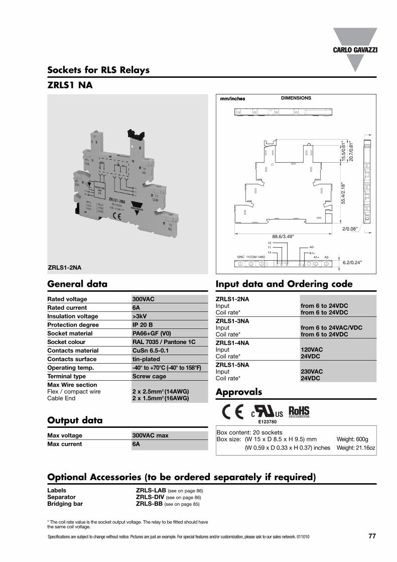
Specifications are subject to change without notice. Pictures are just an example. For special features and/or customization, please ask to our sales network. 011010 77
Sockets for RLS Relays
ZRLS1 NA
ZRLS1-2NA
Rated voltage 300VACRated current 6AInsulation voltage >3kVProtection degree IP 20 B Socket material PA66+GF (V0)Socket colour RAL 7035 / Pantone 1CContacts material CuSn 6.5-0.1Contacts surface tin-platedOperating temp. -40° to +70°C (-40° to 158°F)Terminal type Screw cageMax Wire sectionFlex / compact wire 2 x 2.5mm2 (14AWG)Cable End 2 x 1.5mm2 (16AWG)
88.6/3.49”
15.5
/0.6
1”55
.4/2
.18”
2/0.08”
14NO11COM12NCA1+14
11
DIMENSIONS
General data
mm/inchesmm/inches
Approvals
Box content: 20 socketsBox size: (W 15 x D 8.5 x H 9.5) mm Weight: 600g
(W 0.59 x D 0.33 x H 0.37) inches Weight: 21.16oz
20.7
/0.8
1”
12A2-
A2-A1+
6.2/0.24”
ZRLS1-2NAInput from 6 to 24VDCCoil rate* from 6 to 24VDCZRLS1-3NAInput from 6 to 24VAC/VDCCoil rate* from 6 to 24VDCZRLS1-4NAInput 120VACCoil rate* 24VDCZRLS1-5NAInput 230VACCoil rate* 24VDC
Input data and Ordering code
Optional Accessories (to be ordered separately if required)Labels ZRLS-LAB (see on page 86)Separator ZRLS-DIV (see on page 86)Bridging bar ZRLS-BB (see on page 85)
Max voltage 300VAC maxMax current 6A
Output data
* The coil rate value is the socket output voltage. The relay to be fitted should havethe same coil voltage.
E123780
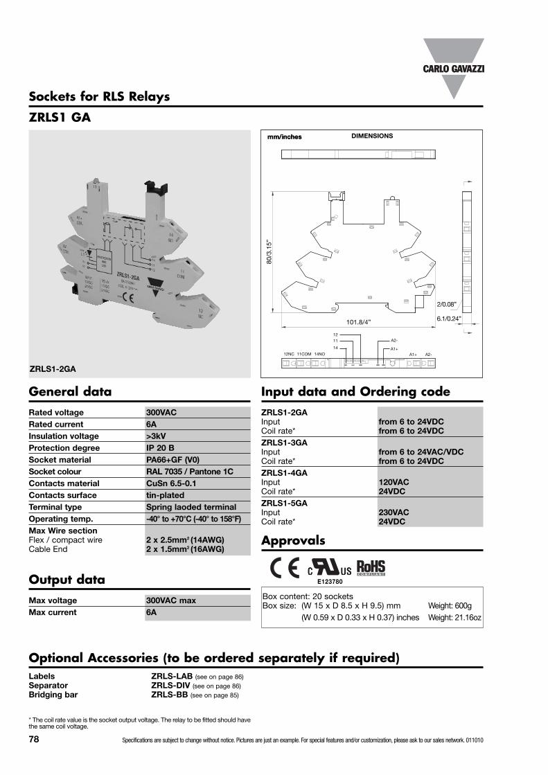
78 Specifications are subject to change without notice. Pictures are just an example. For special features and/or customization, please ask to our sales network. 011010
ZRLS1 GA
ZRLS1-2GA
Rated voltage 300VACRated current 6AInsulation voltage >3kVProtection degree IP 20 B Socket material PA66+GF (V0)Socket colour RAL 7035 / Pantone 1CContacts material CuSn 6.5-0.1Contacts surface tin-platedTerminal type Spring laoded terminalOperating temp. -40° to +70°C (-40° to 158°F)Max Wire sectionFlex / compact wire 2 x 2.5mm2 (14AWG)Cable End 2 x 1.5mm2 (16AWG)
DIMENSIONS
General data
mm/inchesmm/inches
Approvals
Box content: 20 socketsBox size: (W 15 x D 8.5 x H 9.5) mm Weight: 600g
(W 0.59 x D 0.33 x H 0.37) inches Weight: 21.16oz
Sockets for RLS Relays
101.8/4”
80/3
.15”
2/0.08”
14NO11COM12NCA1+14
11
12A2-
A2-A1+
6.1/0.24”
ZRLS1-2GAInput from 6 to 24VDCCoil rate* from 6 to 24VDCZRLS1-3GAInput from 6 to 24VAC/VDCCoil rate* from 6 to 24VDCZRLS1-4GAInput 120VACCoil rate* 24VDCZRLS1-5GAInput 230VACCoil rate* 24VDC
Input data and Ordering code
Optional Accessories (to be ordered separately if required)Labels ZRLS-LAB (see on page 86)Separator ZRLS-DIV (see on page 86)Bridging bar ZRLS-BB (see on page 85)
Max voltage 300VAC maxMax current 6A
Output data
* The coil rate value is the socket output voltage. The relay to be fitted should havethe same coil voltage.
E123780

Optional Function Modules
MODULE 126/230 VDC
-A1
+A2
3/0.12”
2/0.08”
3.4/0.13”7.62/3”
13/0.51” 9/0.35”
23.5
/0.9
3”
31.5
/1.2
4”
12.25/0.48”
5.45/0.21”
1.5/
0.06
”
Type 116/230 VDC
-A1
+A2
36/1
.42”
35/1.38”10/
0.39”
MODULE 42
PackagingBox content: 1 bag, 20pcsWeight: ~150g (5.29oz)
PackagingBox content: 1 bag, 100pcs.Box size: W 160 x D 70 x H 80 mm Weight: ~350g
(W 6.30 x D 2.75 x H 3.15) inches Weight: ~12.3oz
DIMENSIONSmm/inchesmm/inches
Modules for ZMI and ZD sockets
Modules for ZPD sockets
TYPE 21
DIMENSIONSmm/inchesmm/inches
Approvals
European low-voltagedirective compliant
Approvals
European low-voltagedirective compliant
Module material PA66+GF (V0)Module colour RAL 7035 / Pantone 1C
General data
Module material PA66+GF (V0)Module colour RAL 7035 / Pantone 1C
General data
Specifications are subject to change without notice. Pictures are just an example. For special features and/or customization, please ask to our sales network. 011010 79

Diagram Type DescriptionOperating
voltageLED
Colour
Ordering codeNotes
ZMI, ZD, ZDMSockets
ZPD9, ZPD11
-A1
+A2
12 Free wheeling diode A2 + 6 / 230VDC n.a. MODULE12 MODULE11
Only for DCrelays
+A1
-A2
22 Free wheeling diode A1 + 6 / 230VDC n.a. MODULE22 MODULE21
-A1
+A232
Free wheeling diode A2 +,with LED
6 / 24VDCRed
MODULE32
n.a.
24 / 60VDC MODULE32B110 / 230VDC MODULE32C
6 / 24VDCGreen**
MODULE32/G24 / 60VDC MODULE32B/G
110 / 230VDC MODULE32C/G
+A1
-A242
Free wheeling diode A1 +,with LED
6 / 24VDCRed
MODULE4224 / 60VDC MODULE42B
110 / 230VDC MODULE42C6 / 24VDC
Green**MODULE42/G
24 / 60VDC MODULE42B/G110 / 230VDC MODULE42C/G
A1
A252
RC Filter 110/240VAC
n.a.
MODULE52 MODULE51
Only for ACrelays
RC Filter 6 / 24VAC MODULE52B MODULE51B
RC Filter 24 / 60VAC MODULE52D MODULE51D
+A1
-A2
~
~
62Signalling LED
6 / 24V
Red
MODULE62
n.a.Can work with AC
and DC Relays
24 / 60V MODULE62E
92 110 / 230V MODULE92
+A1
-A2
~
~
62Signalling LED
6 / 24V
Green**
MODULE62/G
24 / 60V MODULE62E/G
92 110 / 230V MODULE92/G
62Signalling LED, with
Resistor
6 / 24V
Red
MODULE62C
24 / 60V MODULE62D
92 110 / 230V MODULE92C
62Signalling LED, with
Resistor
6 / 24V
Green**
MODULE62C/G
24 / 60V MODULE62D/G
92 110 / 230V MODULE92C/G
72Resistor
6 / 24VAC
n.a.
MODULE72 MODULE71
115VAC MODULE72A MODULE71A
82 230VAC MODULE82 MODULE81
A1
A2
102 Resistor 110 / 230VAC n.a. MODULE102 n.a.
Types and electrical configurations
** Non standard devices normally not in stock and production upon request
80 Specifications are subject to change without notice. Pictures are just an example. For special features and/or customization, please ask to our sales network. 011010
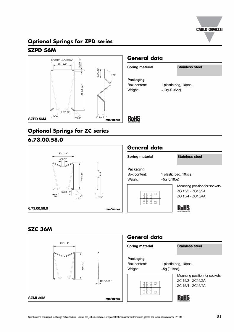
Specifications are subject to change without notice. Pictures are just an example. For special features and/or customization, please ask to our sales network. 011010 81
Optional Springs for ZPD series
SZPD 56M
PackagingBox content: 1 plastic bag, 10pcs.Weight: ~10g (0.36oz)
62.1
/2.4
4”
37±0.2/1.45”±0.007”
13.2
/0.5
2”
mm/inchesmm/inches
Optional Springs for ZC series
6.73.00.58.0
PackagingBox content: 1 plastic bag, 10pcs.Weight: ~5g (0.18oz)
mm/inchesmm/inches
27/1.06”
3.2/
0.12
”
53°
135°
10.7/4.21”
5.5/0.22”
10°
30/1.18”
40/1
.57”
5/0.20”
53°4/1.6”
3.8/0.15”
10°
SZMI 36M
PackagingBox content: 1 plastic bag, 10pcs.Weight: ~5g (0.18oz)
mm/inchesmm/inches
SZPD 56MSZPD 56M
6.73.00.58.0
SZC 36M
Mounting position for sockets:ZC 15/2 - ZC15/2AZC 15/4 - ZC15/4A
Mounting position for sockets:ZC 15/2 - ZC15/2AZC 15/4 - ZC15/4A
Spring material Stainless steel
General data
Spring material Stainless steel
General data
Spring material Stainless steel
General data29/1.14”
36/1
.42”
Ø0.8/0.03”

82 Specifications are subject to change without notice. Pictures are just an example. For special features and/or customization, please ask to our sales network. 011010
Optional Springs for ZMI series, ZR08 and ZDM14A
SZMI 36M
PackagingBox content: 1 plastic bag, 10pcs.Weight: ~5g (0.18oz)
mm/inchesmm/inches
23/0.90”38
/1.5
0”
5/0.20”
53°3.8/0.15”
10°
10/0.39”
6.73.00.61.4
PackagingBox content: 1 plastic bag, 10pcs.Weight: ~20g (0.70oz)59
/2.3
2”
25/0.98”
mm/inchesmm/inches
23/0.91”
SZMI 35
PackagingBox content: 1 plastic bag, 10pcs.Weight: ~20g (0.70oz)59
/2.3
2”
25/0.98”
mm/inchesmm/inches
23/0.91”
SZMI 36M
SZMI 35
6.73.00.61.4
Spring material Stainless steel
General data
Spring material PA66 + GF (V0)Spring colour RAL 7035 / Pantone 1C
General data
Spring material PA6 + GF (V2)Spring colour RAL 7035 / Pantone 1C
General data

Specifications are subject to change without notice. Pictures are just an example. For special features and/or customization, please ask to our sales network. 011010 83
Optional Springs for ZPY series
SZPY 35M
PackagingBox content: 1 plastic bag, 10pcs.Weight: ~10g (0.36oz)
mm/inches
5/0.20”
7/0.27”
0.5/
0.02
”
0.8/0.31”
50.5
/1.9
9”
0.25
/0.9
8”
1.8/
0.7”
Optional Springs for ZY series
SZPY 35M
PackagingBox content: 1 plastic bag, 10pcs.Weight: ~5g (0.18oz)
mm/inchesmm/inches
32/1.30”
38/1
.50”
8/0.31”
53°
3.8/0.15”
10°
SZMI 36M
PackagingBox content: 1 plastic bag, 10pcs.Weight: ~5g (0.18oz)
mm/inchesmm/inches
23/0.90”
38/1
.50”
5/0.20”
53°3.8/0.15”
10°
10/0.39”
SZMI 36M
SZPY 35M
SZY 35M
Only for ZY08
Only for ZY14Note:If the relay has the test buttonoption, it is not possible to use thespring.
Note:For each relay/socket are requiredat least 2 springs.Up to 4 springs can be mounted.
Spring material Stainless steel
General data
Spring material Stainless steel
General data
Spring material Stainless steel
General data
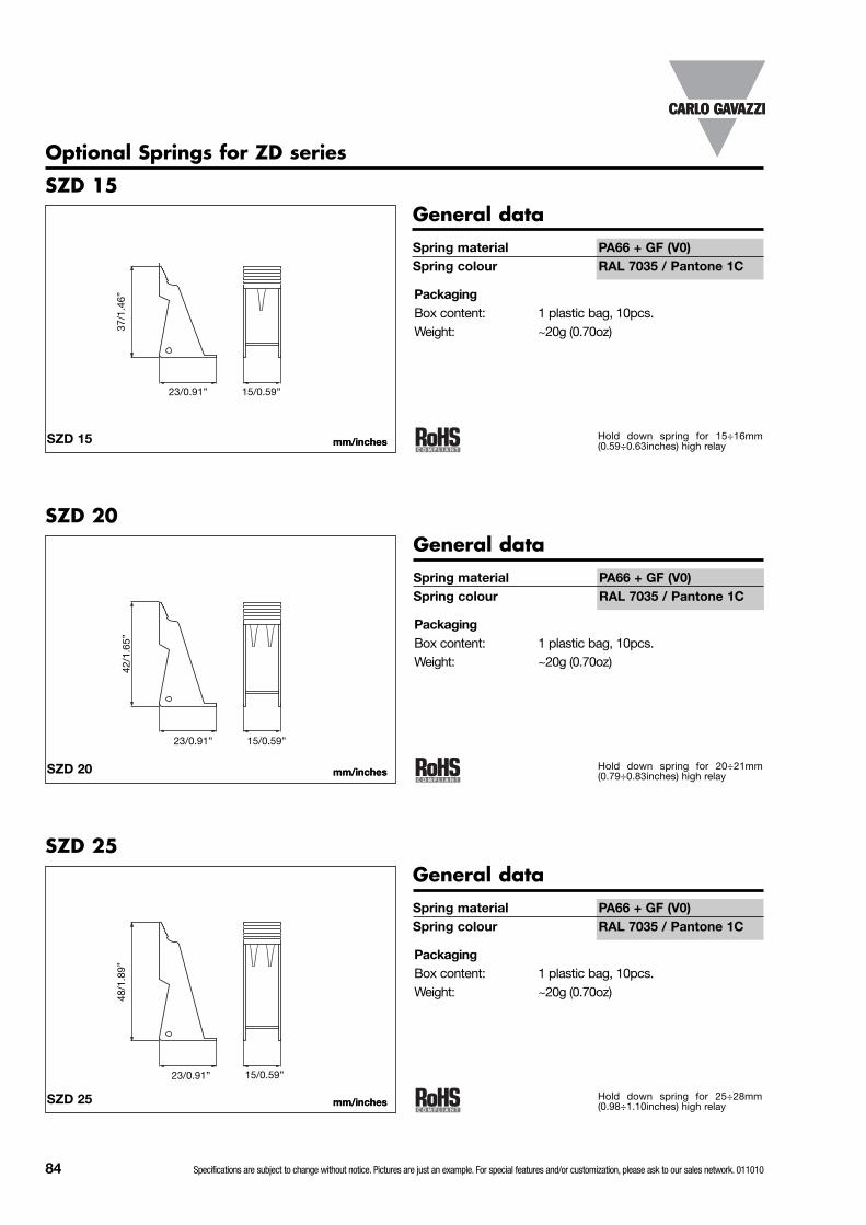
84 Specifications are subject to change without notice. Pictures are just an example. For special features and/or customization, please ask to our sales network. 011010
Optional Springs for ZD series
SZD 15
PackagingBox content: 1 plastic bag, 10pcs.Weight: ~20g (0.70oz)
SZD 20
PackagingBox content: 1 plastic bag, 10pcs.Weight: ~20g (0.70oz)
SZD 25
PackagingBox content: 1 plastic bag, 10pcs.Weight: ~20g (0.70oz)
42/1
.65”
48/1
.89”
mm/inchesmm/inches
mm/inchesmm/inches
mm/inchesmm/inches
15/0.59”
15/0.59”
23/0.91”
23/0.91”
SZD 15
SZD 20
SZD 25
37/1
.46”
15/0.59”23/0.91”
Spring material PA66 + GF (V0)Spring colour RAL 7035 / Pantone 1C
General data
Spring material PA66 + GF (V0)Spring colour RAL 7035 / Pantone 1C
General data
Spring material PA66 + GF (V0)Spring colour RAL 7035 / Pantone 1C
General data
Hold down spring for 15÷16mm(0.59÷0.63inches) high relay
Hold down spring for 20÷21mm(0.79÷0.83inches) high relay
Hold down spring for 25÷28mm(0.98÷1.10inches) high relay

Specifications are subject to change without notice. Pictures are just an example. For special features and/or customization, please ask to our sales network. 011010 85
ZD-BB
PackagingBox content: 1 plastic bag, 10pcs.Weight: ~50g (~1.76oz)
mm/inchesmm/inches
Optional sockets bridging bars
ZD-BB
ZMI-BB
PackagingBox content: 1 plastic bag, 10pcs.Weight: ~50g (~1.76oz)
mm/inchesmm/inches
ZMI-BB
ZRLS-BB
PackagingBox content: 1 plastic bag, 10pcs.Weight: ~50g (~1.76oz)
mm/inchesmm/inches
ZRLS-BB
Plastic insulator material PA66 + GF (V0)Plastic insulator colour BlackMetal jumper Tinned copper
General data
Plastic insulator material PA66 + GF (V0)Plastic insulator colour BlackMetal jumper Tinned copper
General data
Plastic insulator material PA66 + GF (V0)Plastic insulator colour BlackMetal jumper Tinned copper
General data

86 Specifications are subject to change without notice. Pictures are just an example. For special features and/or customization, please ask to our sales network. 011010
Optional labels for ZRLS1-NA and ZRLS1-GA
ZRLS-DIV
PackagingBox content: 1 plastic bag, 10pcs.Weight: ~50g (~1.76oz)
mm/inchesmm/inches
ZRLS-LAB
PackagingBox content: 1 plastic bag, 10pcs.Weight: ~50g (~1.76oz)
mm/inchesmm/inches
Optional separator for ZRLS1-NA and ZRLS1-GA
73/2
.87”
2/0.08”
ZRLS-LAB
ZRLS-DIV
Plastic labels material Polycarbonate (PC)Plastic labels colour White
General data
Plastic separator material PA66Plastic separator colour RAL 7035 / Pantone 1C
General data

CARLO GAVAZZIA u t o m a t i o n C o m p o n e n t s
OUR SALES NETWORK IN EUROPE
OUR SALES NETWORK IN NORTH AMERICA
OUR SALES NETWORK IN ASIA AND PACIFIC
OUR PRODUCTION SITES
Carlo Gavazzi Automation SpAVia Milano, 13 - I-20020 Lainate (MI) - ITALYTel: +39 02 [email protected]/ac
Further information on www.gavazziautomation.com
www.carlogavazzi.com/ac
HEADQUARTERS
FRANCE - Carlo Gavazzi SarlZac de Paris Nord II, 69, rue de la BelleEtoile, F-95956 Roissy CDG CedexTel: +33 1 49 38 98 60Fax: +33 1 48 63 27 [email protected]
GERMANY - Carlo Gavazzi GmbH Rudolf-Diesel-Strasse 23, D-64331 WeiterstadtTel: +49 6151 81000Fax: +49 6151 81 00 [email protected]
GREAT BRITAIN - Carlo Gavazzi UK Ltd7 Springlakes Industrial Estate, Deadbrook Lane, Hants GU12 4UH, GB-AldershotTel: +44 1 252 339600Fax: +44 1 252 326 [email protected]
SPAIN - Carlo Gavazzi SAAvda. Iparraguirre, 80-82, E-48940 Leioa (Bizkaia)Tel: +34 94 480 4037Fax: +34 94 480 10 [email protected]
SWEDEN - Carlo Gavazzi ABNattvindsgatan 1, S-65221 KarlstadTel: +46 54 85 1125Fax: +46 54 85 11 [email protected]
SWITZERLAND - Carlo Gavazzi AGVerkauf Schweiz/Vente SuisseSumpfstrasse 32,CH-632 SteinhausenTel: +41 41 747 4535Fax: +41 41 740 45 [email protected]
AUSTRIA - Carlo Gavazzi GmbH Ketzergasse 374, A-1230 WienTel: +43 1 888 4112Fax: +43 1 889 10 [email protected]
BELGIUM - Carlo Gavazzi NV/SASchaarbeeklei 213/3, B-1800 Vilvoorde Tel: +32 2 257 4120Fax: +32 2 257 41 [email protected]
DENMARK - Carlo Gavazzi Handel A/SOver Hadstenvej 38, DK-8370 HadstenTel: +45 89 60 6100Fax: +45 86 98 15 [email protected]
FINLAND - Carlo Gavazzi OY AB Petaksentie 2-4, FI-00630 HelsinkiTel: +358 9 756 2000Fax: +358 9 756 [email protected]
ITALY - Carlo Gavazzi SpA - Via Milano 13, I-20020 LainateTel: +39 02 931 761Fax: +39 02 931 763 [email protected]
NETHERLANDS - Carlo Gavazzi BV Wijkermeerweg 23, NL-1948 NT BeverwijkTel: +31 251 22 9345Fax: +31 251 22 60 [email protected]
NORWAY - Carlo Gavazzi ASMelkeveien 13, N-3919 PorsgrunnTel: +47 35 93 0800Fax: +47 35 93 08 [email protected]
PORTUGAL - Carlo Gavazzi LdaRua dos Jerónimos 38-B, P-1400-212 LisboaTel: +351 21 361 7060Fax: +351 21 362 13 [email protected]
CANADA - Carlo Gavazzi LTEE 3777 Boulevard du TricentenaireMontreal, Quebec H1B 5W3Tel: +1 514 644 2544Fax: +1 514 644 [email protected]
CANADA - Carlo Gavazzi Inc.2660 Meadowvale Boulevard, CDN-Mississauga Ontario L5N 6M6,Tel: +1 905 542 0979Fax: +1 905 542 22 [email protected]
USA - Carlo Gavazzi Inc.750 Hastings Lane, USA-Buffalo Grove, IL 60089,Tel: +1 847 465 6100Fax: +1 847 465 [email protected]
Carlo Gavazzi Controls SpAControls DivisionBelluno - ITALY
Carlo Gavazzi Controls SpASensors DivisionCastel Maggiore (BO) - ITALY
Carlo Gavazzi Industri A/SHadsten - DENMARK
Uab Carlo Gavazzi Industri KaunasKaunas - LITHUANIA
Carlo Gavazzi LtdZejtun - MALTA
Carlo Gavazzi Automation (Kunshan) Co., Ltd.Kunshan - CHINA
SINGAPORE - Carlo Gavazzi Automation Singapore Pte. Ltd. No. 178 Paya Lebar Road#04-01/05 409030 Singapore Tel: +65 67 466 990Fax: +65 67 461 980
CHINA - Carlo Gavazzi Automation (China) Co. Ltd. Rm. 2308 - 2310, 23/F., News Building, Block 1,1002 Shennan Zhong Road,Shenzhen, ChinaTel: +86 755 83699500Fax: +86 755 83699300
HONG KONG - Carlo Gavazzi AutomationHong Kong Ltd. Unit 3 12/F Crown Industrial Bldg., 106 How Ming St., Kowloon,Hong KongTel: +852 23041228Fax: +852 23443689
MALAYSIA - Carlo GavazziAutomation (M) Sdn Bhd. 54, Jalan Rugbi 13/30,Tadisma Business Park Seksyen1340100 Shah Alam, SelangorTel: +60 3 55 121162Fax: + 60 3 55 126098
CAT
IN
D R
ELAY
EN
G
3.82
.20.
09.1
/00
REV.
1 09
/10