Embed Size (px)
Citation preview
Industrial Hydraulics FAQs
Updated: JS_September2013
FAQ Title: P/Q Amplifier Replacement Category: Electronics Sub-Category: Control Systems
Bosch Rexroth Corporation Hydraulics 2315 City Line Road Bethlehem, PA 18017 Tel (847) 645-3600
Question: What changes or switch settings are necessary when updating to the newer P/Q control amplifiers?
Answer: - Former PQ amplifiers only supported 0 to +10V or 1 to +6V pressure
transducers. Newer PQI amplifiers have these options, but also a third option for a 4 to 20mA pressure transducer. With this expansion of options, there are changes to the wiring and a switch setting which must be addressed.
- Regarding original PQ amplifiers, the electrical connections for a pressure transducer were pin b16 for a 0 to +10V transducer, and pin z14 for the 1 to +6V transducer, with pin b18 being the 0V connection for either version. The PQI amplifier assigns these connections to: pin b16 for the 0 to +10V or 1 to +6V transducers, and pin b18 as the 0V connection. However, with respect to pin z14, a 4 to 20mA transducer would be connected to pins z14 and b18!
- The switch setting affected is switch 1, which must be set to “ON” if a voltage driven pressure transducer is applied. Also remember that switch identification begins with “0”; therefore, switch “1” is actually the second one from the right. Please review the attached data sheets for additional detail and diagrams.
Attachments: RE30058, RE30082, RE30134, UBY13/3, UBY13/84, UBY13/89, UBY13/124, UBY13/125, UBY13/126
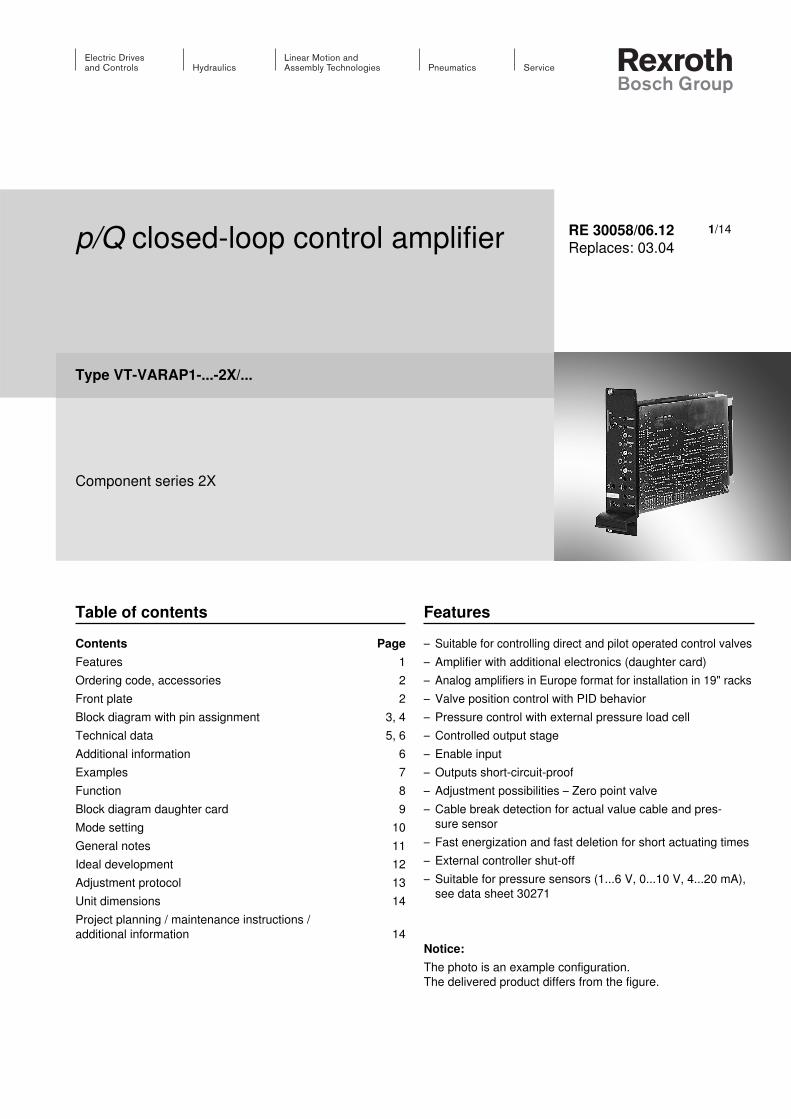
p/Q closed-loop control amplifier
Type VT-VARAP1-...-2X/...
Component series 2X
RE 30058/06.12Replaces: 03.04
Table of contentsContents PageFeatures 1Ordering code, accessories 2Front plate 2Block diagram with pin assignment 3, 4Technical data 5, 6Additional information 6Examples 7Function 8Block diagram daughter card 9Mode setting 10General notes 11Ideal development 12Adjustment protocol 13Unit dimensions 14Project planning / maintenance instructions / additional information 14
Features– Suitable for controlling direct and pilot operated control valves– Amplifier with additional electronics (daughter card) – Analog amplifiers in Europe format for installation in 19" racks– Valve position control with PID behavior– Pressure control with external pressure load cell– Controlled output stage– Enable input– Outputs short-circuit-proof– Adjustment possibilities – Zero point valve– Cable break detection for actual value cable and pres-
sure sensor– Fast energization and fast deletion for short actuating times– External controller shut-off– Suitable for pressure sensors (1...6 V, 0...10 V, 4...20 mA),
see data sheet 30271
Notice:The photo is an example configuration. The delivered product differs from the figure.
1/14
Lvdt
Pot Q
TP Q
Hex KP
Hex KD
Pot p gain
TP p
TP 0 V
Pot p zero
Hex
LED
LEDON
+–
valve+–5%
+UE
QA
QB
–UE
+
UB < UB min.
ON
UB
0V
Q
Regleroff
Q
P
PP
null
KP
KI KI
KD
max max
max
1
9513
1
9513
1
9513
2/14 Bosch Rexroth AG Hydraulics VT-VARAP1-...-2X/... RE 30058/06.12
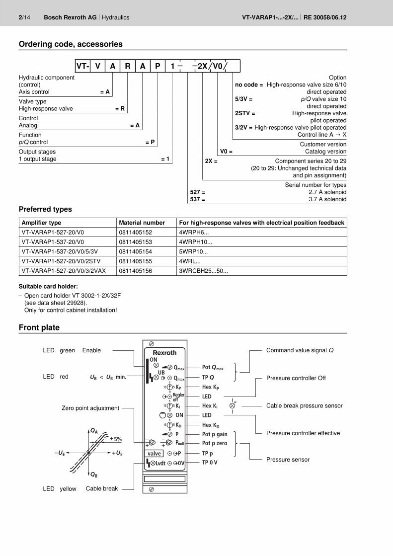
Ordering code, accessories
Front plate
Preferred typesAmplifier type Material number For high-response valves with electrical position feedbackVT-VARAP1-527-20/V0 0811405152 4WRPH6...VT-VARAP1-537-20/V0 0811405153 4WRPH10...VT-VARAP1-537-20/V0/5/3V 0811405154 5WRP10...VT-VARAP1-527-20/V0/2STV 0811405155 4WRL...VT-VARAP1-527-20/V0/3/2VAX 0811405156 3WRCBH25...50...
Hydraulic component (control) Axis control = AValve type High-response valve = RControl Analog = AFunctionp/Q control = POutput stages 1 output stage = 1
Optionno code = High-response valve size 6/10
direct operated5/3V = p/Q valve size 10
direct operated 2STV = High-response valve
pilot operated3/2V = High-response valve pilot operated
Control line A → XCustomer version
V0 = Catalog version2X = Component series 20 to 29
(20 to 29: Unchanged technical data and pin assignment)
Serial number for types527 = 2.7 A solenoid537 = 3.7 A solenoid
LED
LED
LED
green
yellow
Zero point adjustment
Command value signal Q
Pressure controller Off
Cable break pressure sensor
Pressure controller effective
Pressure sensor
red
Enable
Cable break
VT- V A R A P 1 2X V0
Suitable card holder: – Open card holder VT 3002-1-2X/32F
(see data sheet 29928). Only for control cabinet installation!
z32
z22
24 V
=24
V
+10
V
St.–
0 V
max
40
V=
+10
V
10 V
+15
V10
V15
V
DC
DC
15 V
0 V
100
k
100
k
100
k
8.5
V=
max
40
V
5 %
+10
V/1
0 m
A
Ref-
0-
10 V
/10
mA
max
100
mA
z20
0...
10
VU
Eb2
0
b32
b12
z4+
+
+U
B
+U
B 24
V =
0 V
b4 b2 z28
Lvdt
.
z2
z16
b14
2-2
z18
z24
z14
z12
z10
z6b18
b10
b16
b30
b6 b8
1
b24
b30
b22
z30
21
23
4
+U
B
+U
B
+10
V+
0 V
+ +
+U
B
p gai
n
p zer
o
Qm
ax
Us
3-1
3-5
Δ S
0...+
10 V
1-4
6...4
0 V
1...6
V/0
...10
V
1-7
3-2
3-3
3-4
L–0
V1-
1
1-6
DP
I
Ref.
0 V
2-4
4...2
0 m
A
1-5
+15
V
–15
V
+15
V
–15
V
2-1
2-3
0...+
10 V
1-2
0 V
1-3
+
Hydraulics Bosch Rexroth AGRE 30058/06.12 VT-VARAP1-...-2X/... 3/14
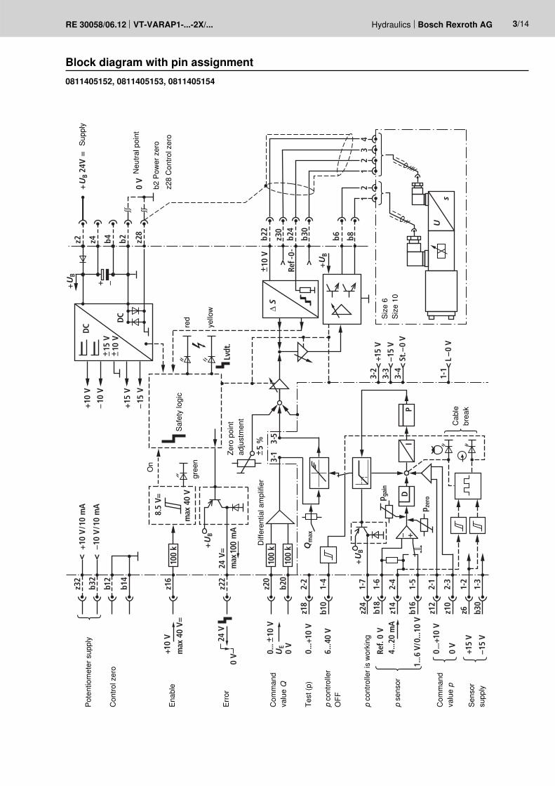
Block diagram with pin assignment0811405152, 0811405153, 0811405154
Supp
ly
Con
trol z
ero
Com
man
d va
lue Q
Test
(p)
p co
ntro
ller
OFF
p co
ntro
ller i
s w
orki
ng
p se
nsor
Com
man
d va
lue p
Sens
or
supp
ly
Pote
ntio
met
er s
uppl
y
Enab
le
Erro
r
On
red
yello
w
gree
n
Safe
ty lo
gic
Zero
poi
nt
adju
stm
ent
Diff
eren
tial a
mpl
ifier
Cab
le
brea
k
Neu
tral p
oint
b2 P
ower
zer
oz2
8 C
ontro
l zer
o
Size
6
Size
10
z32
z22
24 V
=24
V
+10
V
St.–
0 V
max
40
V=
+10
V
10 V
+15
V10
V15
V
DC
DC
15 V
0 V
100
k
100
k
100
k
8.5
V=
max
40
V
5 %
+10
V/1
0 m
A
Ref-
0-
10 V
/10
mA
max
100
mA
z20
0...
10
VU
Eb2
0
b32
b12
z4++U
B
+U
B 24
V =
0 V
b4 b2 z28
Lvdt
.
z2
z16
b14
2-2
z18
z24
z14
z12
z10
z6b18
b10
b16
b30
b6 b8
1
b24
b30
b22
z30
21
23
4
+U
B
+U
B
+10
V+
+
0 V
+ +
+U
B
Qm
ax
3-1
3-5
Δ S
Ref-
0-b2
8
b30
b26
z30
12
34
10 V
+Δ
S
0...+
10 V
1-4
6...4
0 V
1...6
V/0
...10
V
1-7
3-2
3-3
3-4
L–0
V1-
1
1-6
DP
I
Ref.
0 V
2-4
4...2
0 m
A
1-5
+15
V
–15
V
+15
V
–15
V
2-1
2-3
0...+
10 V
1-2
0 V
1-3
+
Us
Us
p gai
n
p zer
o
4/14 Bosch Rexroth AG Hydraulics VT-VARAP1-...-2X/... RE 30058/06.12
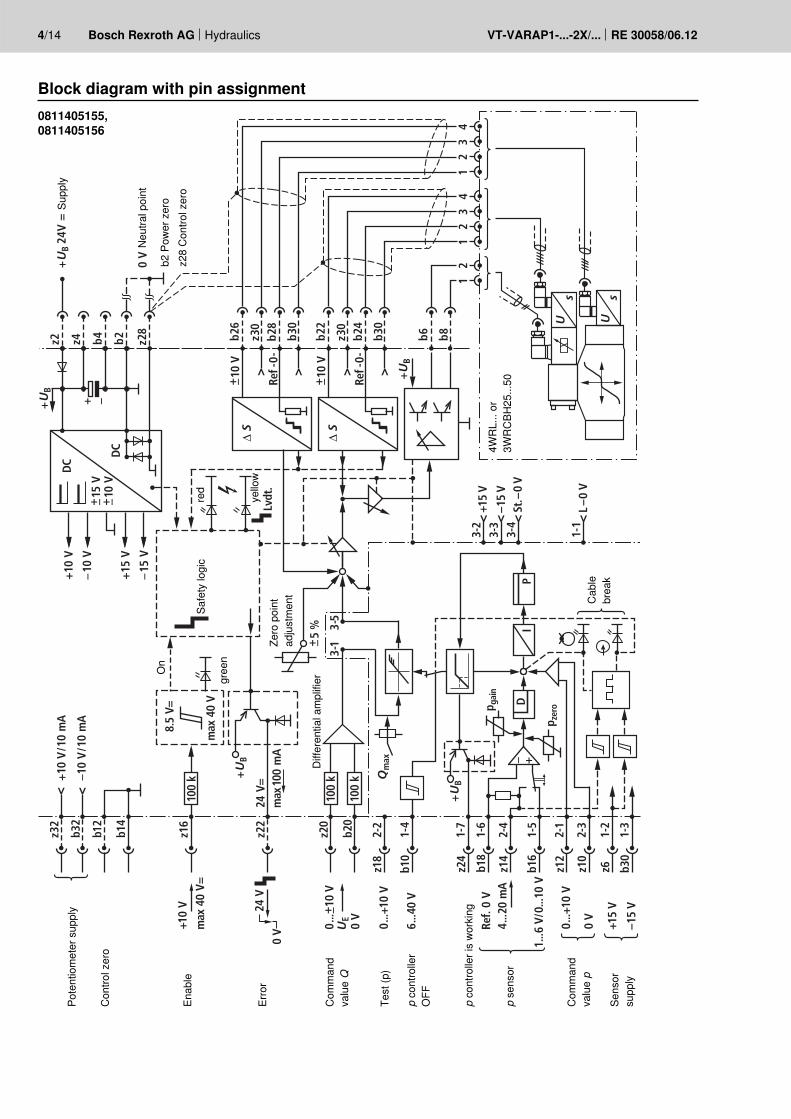
Block diagram with pin assignment0811405155,0811405156
Supp
ly
Con
trol z
ero
Com
man
d va
lue Q
Test
(p)
p co
ntro
ller
OFF
p co
ntro
ller i
s w
orki
ng
p se
nsor
Com
man
d va
lue p
Sens
or
supp
ly
Pote
ntio
met
er s
uppl
y
Enab
le
Erro
r
On
red
yello
w
gree
n
Safe
ty lo
gic
Diff
eren
tial a
mpl
ifier
Cab
le
brea
k
Neu
tral p
oint
b2 P
ower
zer
oz2
8 C
ontro
l zer
o
4WR
L...
or
3WR
CBH
25...
50
Zero
poi
nt
adju
stm
ent
Hydraulics Bosch Rexroth AGRE 30058/06.12 VT-VARAP1-...-2X/... 5/14
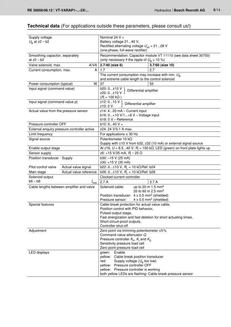
Technical data (For applications outside these parameters, please consult us!)
Supply voltageUB at z2 – b2
Nominal 24 V = Battery voltage 21...40 V, Rectified alternating voltage Ueff = 21...28 V (one-phase, full-wave rectifier)
Smoothing capacitor, separately at z2 – b2
Recommendation: Capacitor module VT 11110 (see data sheet 30750) (only necessary if the ripple of UB > 10 %)
Valve solenoid, max. A/VA 2.7/40 (size 6) 3.7/60 (size 10)Current consumption, max. A 1.7 2.7
The current consumption may increase with min. UB and extreme cable length to the control solenoid
Power consumption (typical) W 37 55Input signal (command value) b20: 0...±10 V
z20: 0...±10 V }Differential amplifier
(Ri = 100 kΩ )Input signal (command value p) z12: 0...10 V
z10: 0 V }Differential amplifier
Actual value from the pressure sensor z14: 4...20 mA – Current input b16: 0...+10 V/1...+6 V – Voltage input b18: 0 V – Reference
Pressure controller OFF b10: 6...40 V =External enquiry pressure controller active z24: 24 V/0.1 A max.Limit frequency For applications ≦ 30 HzSignal source Potentiometer 10 kΩ
Supply with ±10 V from b32, z32 (10 mA) or external signal sourceEnable output stage At z16, U = 8.5...40 V, Ri = 100 kΩ, LED (green) on front plate lights upSensor supply z6: +15 V/35 mA, Ri ~ 25 ΩPosition transducer Supply b30: –15 V (25 mA)
z30: +15 V (35 mA)Pilot control valve Actual value signal b22: 0...±10 V, RL = 10 kΩ/Ref. b24Main stage Actual value reference b26: 0...±10 V, RL = 10 kΩ/Ref. b28Solenoid output b6 – b8 Imax
Clocked current controller2.7 A 3.7 A
Cable lengths between amplifier and valve Solenoid cable: up to 20 m 1.5 mm2
20 to 60 m 2.5 mm2
Position transducer: 4 x 0.5 mm2 (shielded) Pressure sensor: 4 x 0.5 mm2 (shielded)
Special features Cable break protection for actual value cable, Position control with PID behavior, Pulsed output stage, Fast energization and fast deletion for short actuating times, Short-circuit-proof outputs, Controller shut-off
Adjustment Zero point via trimming potentiometer ±5 % Command value attenuator QPressure controller KP, KI and KDSensitivity pressure load cell Zero point pressure load cell
LED displays green: Enable yellow: Cable break position transducer red: Supply voltage (UB too low) yellow: Pressure controller OFF yellow: Pressure controller is working both yellow LEDs are flashing: Cable break pressure sensor
6/14 Bosch Rexroth AG Hydraulics VT-VARAP1-...-2X/... RE 30058/06.12
Technical data (For applications outside these parameters, please consult us!)
Additional information
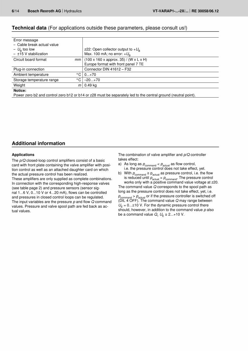
Error message– Cable break actual value– UB too low– ±15 V stabilization
z22: Open collector output to +UBMax. 100 mA; no error: +UB
Circuit board format mm (100 x 160 x approx. 35) / (W x L x H)Europe format with front panel 7 TE
Plug-in connection Connector DIN 41612 – F32Ambient temperature °C 0...+70Storage temperature range °C –20...+70Weight m 0.49 kgNotice:Power zero b2 and control zero b12 or b14 or z28 must be separately led to the central ground (neutral point).
ApplicationsThe p/Q closed-loop control amplifiers consist of a basic card with front plate containing the valve amplifier with posi-tion control as well as an attached daughter card on which the actual pressure control has been realized. These amplifiers are only supplied as complete combinations. In connection with the corresponding high-response valves (see table page 2) and pressure sensors (sensor sig-nal 1...6 V, 0...10 V or 4...20 mA), flows can be controlled and pressures in closed control loops can be regulated. The input variables are the pressure p and flow Q command values. Pressure and valve spool path are fed back as ac-tual values.
The combination of valve amplifier and p/Q controller takes effect:a) As long as pcommand < pactual as flow control,
i.e. the pressure control does not take effect, yet.b) With pcommand ≧ pactual as pressure control, i.e. the flow
is reduced until pactual = pcommand. The pressure control works only with a positive command value voltage at z20.
The command value Q corresponds to the spool path as long as the pressure control does not take effect, yet, i.e. pcommand > pactual or if the pressure controller is switched off (DIL 4 OFF). The command value Q may range between UE = 0...±10 V. For the dynamic pressure control there should, however, in addition to the command value p also be a command value Q1 UE ≧ 2...+10 V.
A B
P
p
TG
+
U
A B
P
p
TG
+
U
Hydraulics Bosch Rexroth AGRE 30058/06.12 VT-VARAP1-...-2X/... 7/14
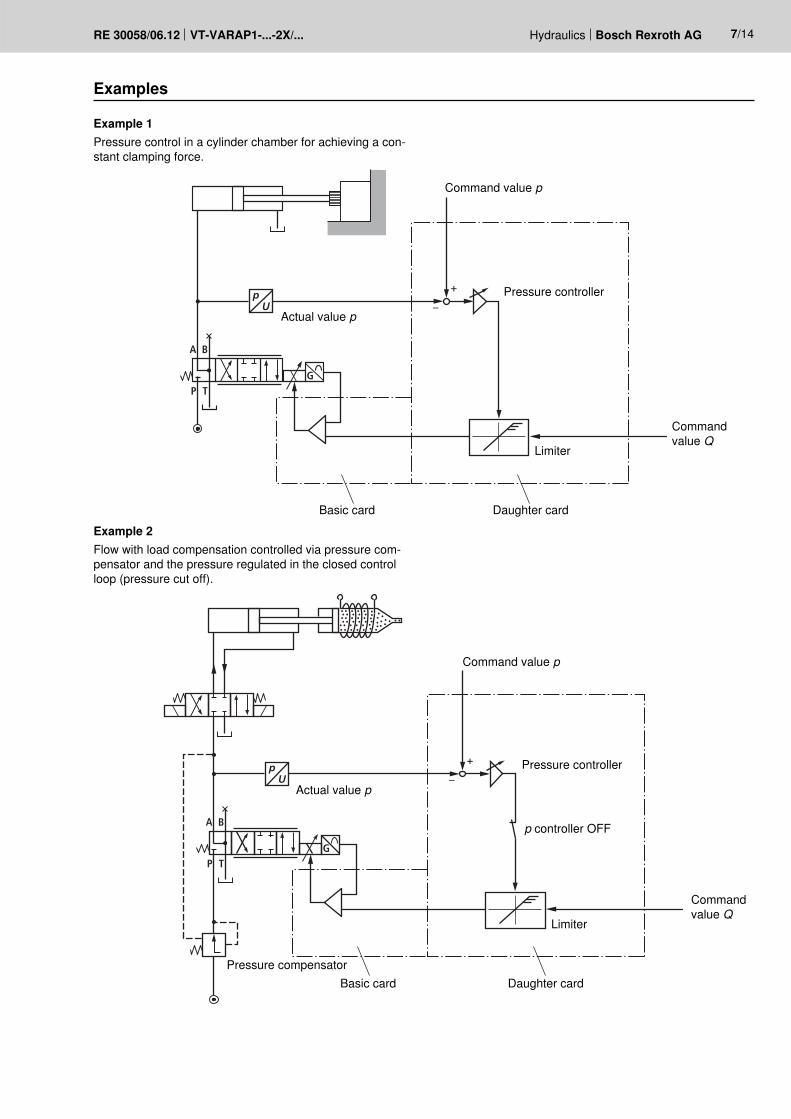
Examples
Example 1Pressure control in a cylinder chamber for achieving a con-stant clamping force.
Example 2Flow with load compensation controlled via pressure com-pensator and the pressure regulated in the closed control loop (pressure cut off).
Command value p
Command value p
Actual value p
Actual value p
Pressure compensator
Pressure controller
Pressure controller
p controller OFF
Limiter
Limiter
Daughter card
Daughter card
Basic card
Basic card
Command value Q
Command value Q
+
TV IT
KP
b18b12
Isig
Usup z6
z14
0 V/
0 V
0 V/P PP
UI Ub18b12
Usig
Usup z6
b18
sig
sig
U
supU z6b12
b16b16
b18
8/14 Bosch Rexroth AG Hydraulics VT-VARAP1-...-2X/... RE 30058/06.12
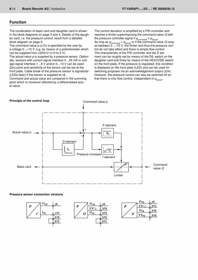
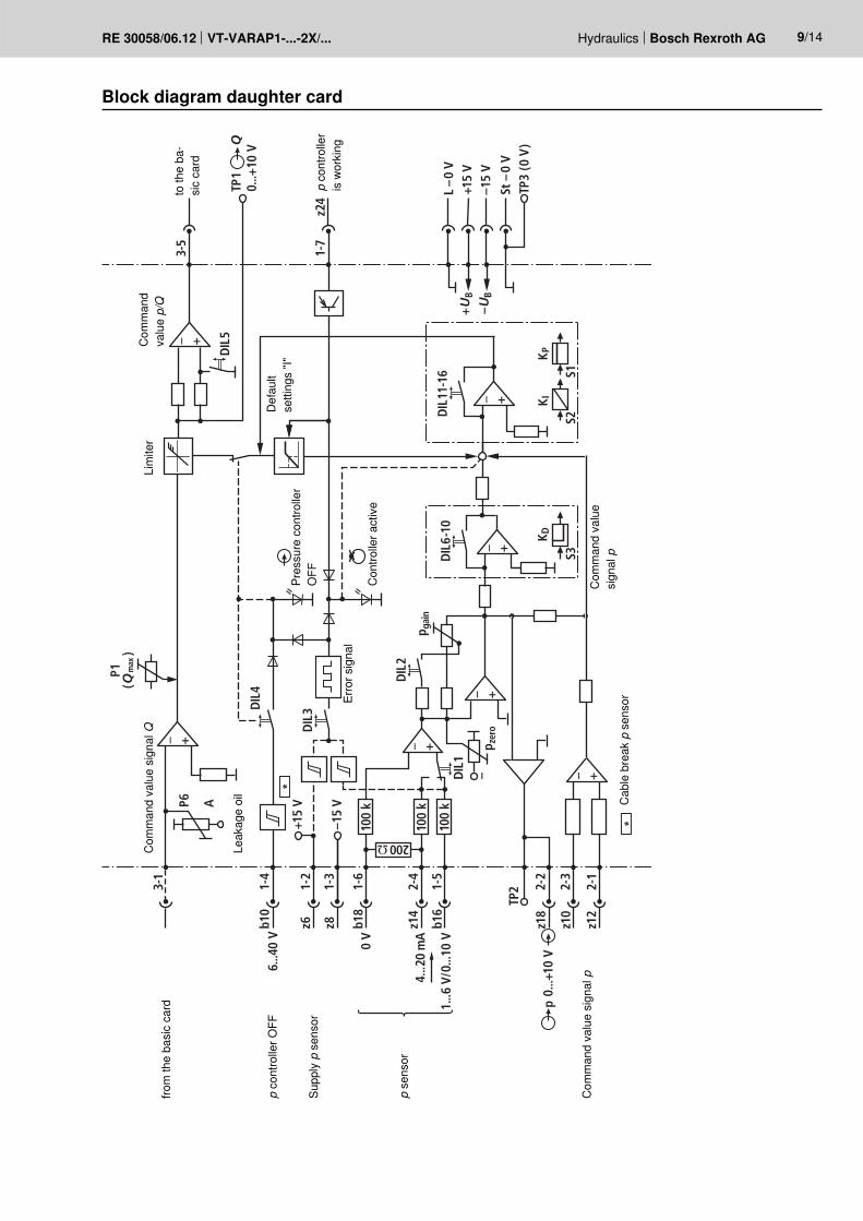
Function
The combination of basic card and daughter card is shown in the block diagrams on page 3 and 4. Details of the daugh-ter card, i.e. the pressure control, result from a detailed block diagram on page 9.The command value p (z12) is specified by the user by a voltage 0...+10 V, e.g. by means of a potentiometer which can be supplied from z32/b12 (z10 to 0 V).The actual value p is supplied by a pressure sensor. Option-ally, sensors with current signal interface 4…20 mA or volt-age signal interface 1…6 V and/or 0…10 V can be used.Zero point and sensitivity of the sensor can be set at the front plate. Cable break of the pressure sensor is signalized (LEDs flash) if the sensor is supplied at z6.Command and actual value are compared in the summing point which is moreover affected by a differentiated actu-al value.
The control deviation is amplified by a PID controller and reaches a limiter superimposing the command value Q with the pressure controller signal if pcommand ≦ pactual.As long as pcommand > pactual or if the command value Q rang-es between 0…–10 V, the limiter and thus the pressure con-trol do not take effect and there is simple flow control.The characteristic of the PID controller and the D ele-ment can be roughly set by means of the DIL switch on the daughter card and finely by means of the HEXCODE switch on the front plate. If the pressure is regulated, this condition is displayed on the front plate (LED) and can be used for switching purposes via an acknowledgement output (z24). However, the pressure control can also be switched off so that there is only flow control, independent of pactual.
Principle of the control loop
Pressure sensor connection versions
Command value p
Actual value p
Pressure increase
P element
D element
I element
Limiter
Basic card Command value Q
K
+U
B
–UB
+15
V–1
5 V
–
L –0
V
TP3
(0 V
)
TP1
St –
0 V
3-1
3-5
1-7
z24
1-4
1-2
1-3
1-6
2-4
1-5
b10
P6 A
*z6 z8 b1
8
z14
b16
z18
pz1
0
z12
TP2 2-
2
2-3
2-1
0 V
4...2
0 m
A
1...6
V/0
...10
V
0...+
10 V
6...4
0 V
+15
V
DIL
4
DIL
3
DIL
5
DIL
2
DIL
6-10
DIL
11-1
6D
IL1
–15
V
0...+
10 V
+ +
+
+
+
*
+
+
100
k
100
k
P1(Q
)
S3S2
S1
200 Ω
100
k
PK I
K D
Q
max
p gai
n
p zer
o
Hydraulics Bosch Rexroth AGRE 30058/06.12 VT-VARAP1-...-2X/... 9/14
Block diagram daughter card
from
the
basi
c ca
rdto
the
ba-
sic
card
p co
ntro
ller O
FF
p co
ntro
ller
is w
orki
ng
p se
nsor
Com
man
d va
lue
sign
al p
Com
man
d va
lue
sign
al Q
Lim
iter
Com
man
d va
lue p/Q
Com
man
d va
lue
sign
al p
Supp
ly p
sen
sor
Pres
sure
con
trolle
r O
FF
Erro
r sig
nal
Leak
age
oil
Con
trolle
r act
ive
Def
ault
setti
ngs
"I"
Cab
le b
reak
p s
enso
r
10/14 Bosch Rexroth AG Hydraulics VT-VARAP1-...-2X/... RE 30058/06.12
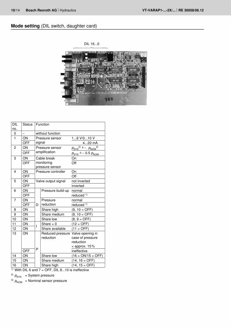
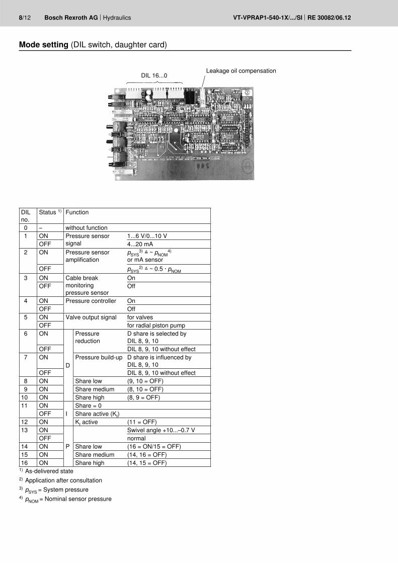
Mode setting (DIL switch, daughter card)
DIL no.
Status Function
0 – without function 1 ON Pressure sensor
signal1...6 V/0...10 V
OFF 4...20 mA 2 ON Pressure sensor
amplificationpSYS
2) ≙ ∼ pNOM3)
OFF pSYS ≙ ∼ 0.5 pNOM 3 ON Cable break
monitoring pressure sensor
OnOFF Off
4 ON Pressure controller OnOFF Off
5 ON Valve output signal not invertedOFF inverted
6 ON
D
Pressure build-up normalOFF reduced 1)
7 ON Pressure reduction
normalOFF reduced 1)
8 ON Share high (9, 10 = OFF) 9 ON Share medium (8, 10 = OFF)10 ON Share low (8, 9 = OFF)11 ON I Share = 0 (12 = OFF)12 ON Share available (11 = OFF)13 ON
P
Reduced pressure reduction
Valve opening in case of pressure reduction < approx. 15 %
OFF ineffective14 ON Share low (16 = ON/15 = OFF)15 ON Share medium (14, 16 = OFF)16 ON Share high (14, 15 = OFF)
1) With DIL 6 and 7 = OFF, DIL 8...10 is ineffective2) pSYS = System pressure3) pNOM = Nominal sensor pressure
DIL 16...0
Hydraulics Bosch Rexroth AGRE 30058/06.12 VT-VARAP1-...-2X/... 11/14
General notes:
Setting during the commissioning is effected using potenti-ometers and HEXCODE switches on the front plate as well as using DIL switches on the daughter card bottom side. Test points for voltage measurements as well as LED dis-plays are located on the front plate. The measured values generally refer to the test point 0 V. The test points may only be loaded with measuring instruments RL ≧ 10 kΩ. Overload impairs the control function and/or the printed circuit board is damaged.
Before the commissioning, the basic settings of the as-delivered state are to be checked. In the card comparison, proceed in the order of the points shown:
A: Adjustment of the valve zero point (basic card front plate)
1) DIL 4 OFF (pressure controller OFF)2) Applying the voltage and pressure supply3) Command value specification Q = 0 V4) Use the "Zero"
potentiometer to bring the cylinder to a standstill
C: Comparison – command value Q1) Specification Qcommand = 10 V2) Limitation of the max. valve opening
(50...100 % opening) by potentiometer "Qmax". Control of the voltage value at TP "Qmax": 10 V ≙ 100 % Valve opening (with Qcommand = 10 V) 5 V ≙ 50 % Valve opening (with Qcommand = 10 V)
B: Pressure sensor comparison1) Sensor type selection
DIL 1 ON ≙ UA = 1...6 V/0...10 V OFF ≙ UA = 4...20 mA2) Sensor amplification selection
DIL 2 ON if pSYS ~ pNOM OFF if 0.5 · pNOM ≦ pSYS ≦ pNOM
3) Hydraulic supply OFF4) Zero point calibration with potentiometer
"PZero" (at TP " " = 0 V)5) Hydraulic supply ON – max. system pressure6) Sensitivity adjustment with potentiometer " P"
(at TP " P" = 10 V)
D: Controller adjustmentThe P, I and D shares of the closed-loop control ampli-fier are to be optimized according to the properties of the control distance, the disturbance variables and the static and dynamic requirements on the control result.
1) Pressure controller ON – DIL 4 ON2) Connection of an oscilloscope at terminals z18 and
b12 (0 V) pactual3) Usefully connection of a 2nd oscilloscope channel at
z2 and z10 (0 V) pcommand4) DIL 6 and DIL 7 serve to compensate dynamic dif-
ferences in the pressure build-up and reduction in the system DIL 6 ON = Normal application OFF = Special application DIL 7 ON = Normal application OFF = Special application
5) DIL 13 – reduces the pressure reduction by means of a valve opening < approx. 15 % ON = Special application OFF = Normal application6) Aim of the controller optimization
An optimum between change over characteristic (over-shooting tendency with excessive static amplification) and static accuracy (control error with starting pressure cut off) is to be achieved (a).
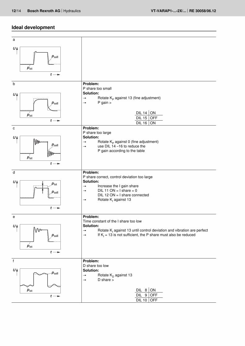
Procedure (see table, page 12)An increase in the P share of the controller increases the dynamic of the control behavior (b). In case of excessive gain, the tendency to oscillate increases (c). Limitation of the I share reduces the static gain. With increasing static gain, the control deviation is reduced (d). The D share can be used to influence the transition be-havior (minimization of the tendency to oscillate); thus, the command value is only reached after a longer transi-tion time (f).
12/14 Bosch Rexroth AG Hydraulics VT-VARAP1-...-2X/... RE 30058/06.12
a
ist
soll
U
t
p
p
b
sollp
ist
U
t
p
Problem:P share too smallSolution: Rotate KP against 13 (fine adjustment) P gain >
DIL 14 ONDIL 15 OFFDIL 16 ON
c
sollp
istp
U
t
Problem:P share too largeSolution: Rotate KP against 0 (fine adjustment) use DIL 14 –16 to reduce the
P gain according to the table
d
ist
soll
U
t
p
p
Problem:P share correct, control deviation too largeSolution: Increase the I gain share DIL 11 ON = I share = 0
DIL 12 ON = I share connected Rotate KI against 13
e
istp
soll
U
t
p
Problem:Time constant of the I share too lowSolution: Rotate KI against 13 until control deviation and vibration are perfect If KI = 13 is not sufficient, the P share must also be reduced
f
istp
sollU
t
p
Problem:D share too lowSolution: Rotate KD against 13 D share >
DIL 8 ONDIL 9 OFFDIL 10 OFF
Ideal development
Hydraulics Bosch Rexroth AGRE 30058/06.12 VT-VARAP1-...-2X/... 13/14
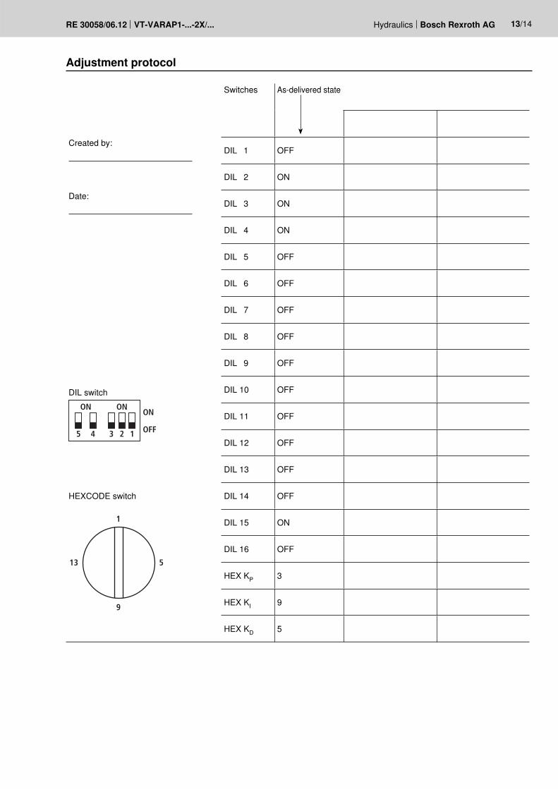
Adjustment protocol
Switches As-delivered state
Created by:
DIL 1 OFF
DIL 2 ON
Date:
DIL 3 ON
DIL 4 ON
DIL 5 OFF
DIL 6 OFF
DIL 7 OFF
DIL 8 OFF
DIL 9 OFF
DIL switch
12345
ON ONON
OFF
DIL 10 OFF
DIL 11 OFF
DIL 12 OFF
DIL 13 OFF
HEXCODE switch DIL 14 OFF
1
9
13 5
DIL 15 ON
DIL 16 OFF
HEX KP 3
HEX KI 9
HEX KD 5

35
100
24
V=
DIN 41612 - F 32
160
14/14 Bosch Rexroth AG Hydraulics VT-VARAP1-...-2X/... RE 30058/06.12
Bosch Rexroth AG HydraulicsZum Eisengießer 197816 Lohr am Main, GermanyPhone +49 (0) 93 52 / [email protected]
© This document, as well as the data, specifications and other informa-tion set forth in it, are the exclusive property of Bosch Rexroth AG. It may not be reproduced or given to third parties without its consent.The data specified above only serve to describe the product. No state-ments concerning a certain condition or suitability for a certain applica-tion can be derived from our information. The information given does not release the user from the obligation of own judgment and verification. It must be remembered that our products are subject to a natural process of wear and aging.
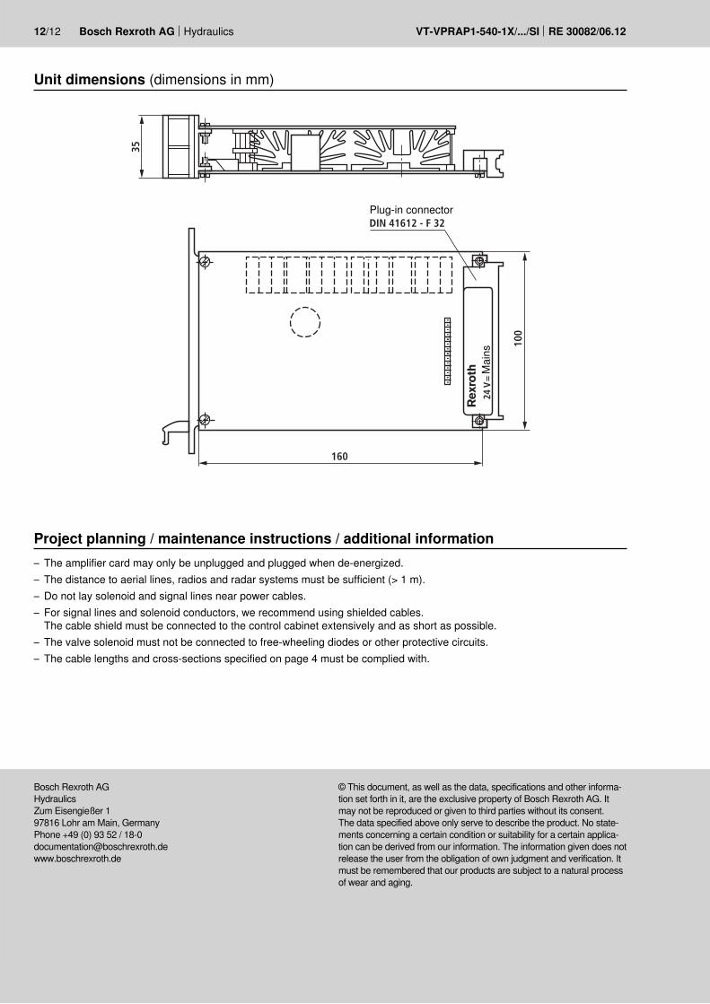
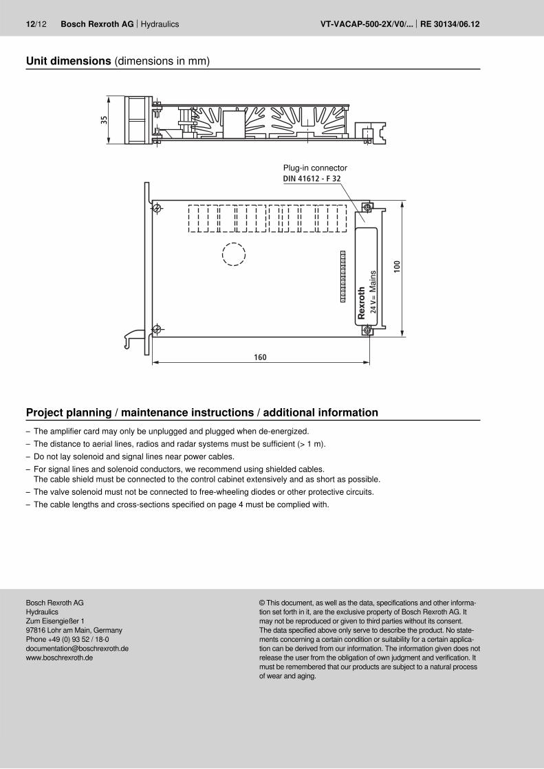
Unit dimensions (dimensions in mm)
Plug-in connector
Mai
ns
Project planning / maintenance instructions / additional information– The amplifier card may only be unplugged and plugged when de-energized.– The distance to aerial lines, radios and radar systems must be sufficient (> 1 m).– Do not lay solenoid and signal lines near power cables.– For signal lines and solenoid conductors, we recommend using shielded cables.
The cable shield must be connected to the control cabinet extensively and as short as possible.– The valve solenoid must not be connected to free-wheeling diodes or other protective circuits.– The cable lengths and cross-sections specified on page 5 must be complied with.

Hydraulics Bosch Rexroth AGRE 30058/06.12 VT-VARAP1-...-2X/...
Bosch Rexroth AG HydraulicsZum Eisengießer 197816 Lohr am Main, GermanyPhone +49 (0) 93 52 / [email protected]
© This document, as well as the data, specifications and other informa-tion set forth in it, are the exclusive property of Bosch Rexroth AG. It may not be reproduced or given to third parties without its consent.The data specified above only serve to describe the product. No state-ments concerning a certain condition or suitability for a certain applica-tion can be derived from our information. The information given does not release the user from the obligation of own judgment and verification. It must be remembered that our products are subject to a natural process of wear and aging.
Notes

VT-VARAP1-...-2X/... RE 30058/06.12
Bosch Rexroth AG HydraulicsZum Eisengießer 197816 Lohr am Main, GermanyPhone +49 (0) 93 52 / [email protected]
© This document, as well as the data, specifications and other informa-tion set forth in it, are the exclusive property of Bosch Rexroth AG. It may not be reproduced or given to third parties without its consent.The data specified above only serve to describe the product. No state-ments concerning a certain condition or suitability for a certain applica-tion can be derived from our information. The information given does not release the user from the obligation of own judgment and verification. It must be remembered that our products are subject to a natural process of wear and aging.
Bosch Rexroth AG Hydraulics
Notes
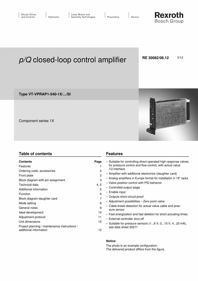
p/Q closed-loop control amplifier
Type VT-VPRAP1-540-1X/.../SI
Component series 1X
RE 30082/06.12
Table of contentsContents Page Features 1Ordering code, accessories 2Front plate 2Block diagram with pin assignment 3Technical data 4, 5Additional information 5Function 6Block diagram daughter card 7Mode setting 8General notes 9Ideal development 10Adjustment protocol 11Unit dimensions 12Project planning / maintenance instructions / additional information 12
Features – Suitable for controlling direct operated high-response valves
for pressure control and flow control, with actual value I/U interface
– Amplifier with additional electronics (daughter card) – Analog amplifiers in Europe format for installation in 19" racks– Valve position control with PID behavior– Controlled output stage– Enable input– Outputs short-circuit-proof– Adjustment possibilities – Zero point valve– Cable break detection for actual value cable and pres-
sure sensor– Fast energization and fast deletion for short actuating times– External controller shut-off– Suitable for pressure sensors (1...6 V, 0...10 V, 4...20 mA),
see data sheet 30271
Notice:The photo is an example configuration. The delivered product differs from the figure.
1/12
2/12 Bosch Rexroth AG Hydraulics VT-VPRAP1-540-1X/.../SI RE 30082/06.12
Lvdt
Pot Q
TP Q
Hex KP
Hex KD
Pot p gain
TP p
TP 0 V
Pot p zero
Hex
LED
LEDON
+–
valve+–5%
+UE
QA
QB
–UE
+
UB < UB min.
ON
UB
0V
Q
Regleroff
Q
P
PP
null
KP
KI KI
KD
max max
max
1
9513
1
9513
1
9513
VT- V P R A P 1 540 1X V0 SI
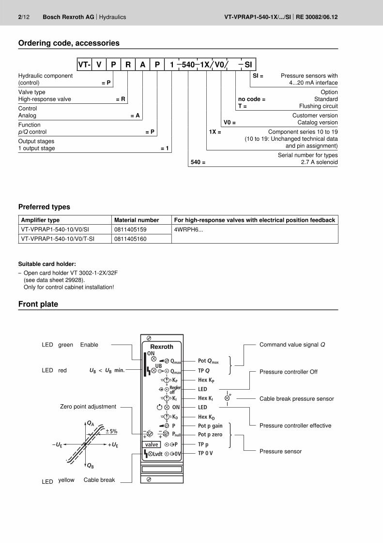
Ordering code, accessories
Front plate
Preferred typesAmplifier type Material number For high-response valves with electrical position feedbackVT-VPRAP1-540-10/V0/SI 0811405159 4WRPH6...VT-VPRAP1-540-10/V0/T-SI 0811405160
Hydraulic component (control) = PValve type High-response valve = RControl Analog = AFunctionp/Q control = POutput stages 1 output stage = 1
SI = Pressure sensors with 4...20 mA interface
Optionno code = StandardT = Flushing circuit
Customer versionV0 = Catalog version
1X = Component series 10 to 19 (10 to 19: Unchanged technical data
and pin assignment)Serial number for types
540 = 2.7 A solenoid
LED
LED
LED
green
yellow
Zero point adjustment
Command value signal Q
Pressure controller Off
Cable break pressure sensor
Pressure controller effective
Pressure sensor
red
Enable
Cable break
Suitable card holder: – Open card holder VT 3002-1-2X/32F
(see data sheet 29928). Only for control cabinet installation!
Hydraulics Bosch Rexroth AGRE 30082/06.12 VT-VPRAP1-540-1X/.../SI
z32
z22
24 V
=24
V
+10
V
St.–
0 V
max
40
V=
+10
V
10 V
+15
V10
V15
V
DC
DC
15 V
0 V
100
k
100
k
100
k
8.5
V=
max
40
V
5 %
+10
V/1
0 m
A
Ref-
0-
10 V
/10
mA
max
100
mA
z20
0...
24
VU
Eb2
0
b32
b12
z4++U
B
+U
B 24
V =
0 V
b4 b2 z28
Lvdt
.
z2
z16
P62-
2z1
8
z24
z14
z12
z10
z6b18
b10
b16
b30
b6 b8
1
b24
b30
b22
z30
21
23
4
+U
B
+U
B
+10
V+
+
0 V
+ +
+U
B
p gai
n
p zer
o
Qm
axp
,Q
b14
3-1
A
A
3-5
Δ S
Ref-
0-b2
8
b30
b26
z30
12
34
10 V
+Δ
S
0...+
10 V
1-4
6...4
0 V
1-7
3-2
3-3
3-4
L–0
V1-
1
1-6
DP
I
Ref.
0 V
2-4
1-5
+15
V
–15
V
+15
V
–15
V
2-1
2-3
0...+
10 V
4...2
0 m
A
1...6
V/0
...10
V
1-2
0 V
3-3
Us
Us
DIL
2
DIL
1
1)
2)
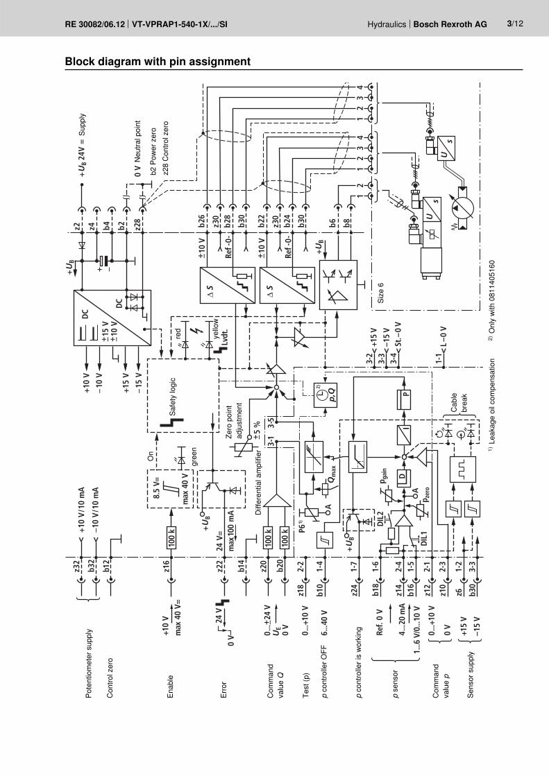
3/12
Block diagram with pin assignmentSu
pply
Con
trol z
ero
Com
man
d va
lue Q
Test
(p)
p co
ntro
ller O
FF
p co
ntro
ller i
s w
orki
ng
p se
nsor
Com
man
d va
lue p
Sens
or s
uppl
y
Pote
ntio
met
er s
uppl
y
Enab
le
Erro
r
On
red
yello
w
gree
n
Safe
ty lo
gic
Diff
eren
tial a
mpl
ifier
Cab
le
brea
k
Neu
tral p
oint
b2 P
ower
zer
oz2
8 C
ontro
l zer
o
Size
6
Zero
poi
nt
adju
stm
ent
1) L
eaka
ge o
il co
mpe
nsat
ion
2) O
nly
with
081
1405
160
4/12 Bosch Rexroth AG Hydraulics VT-VPRAP1-540-1X/.../SI RE 30082/06.12
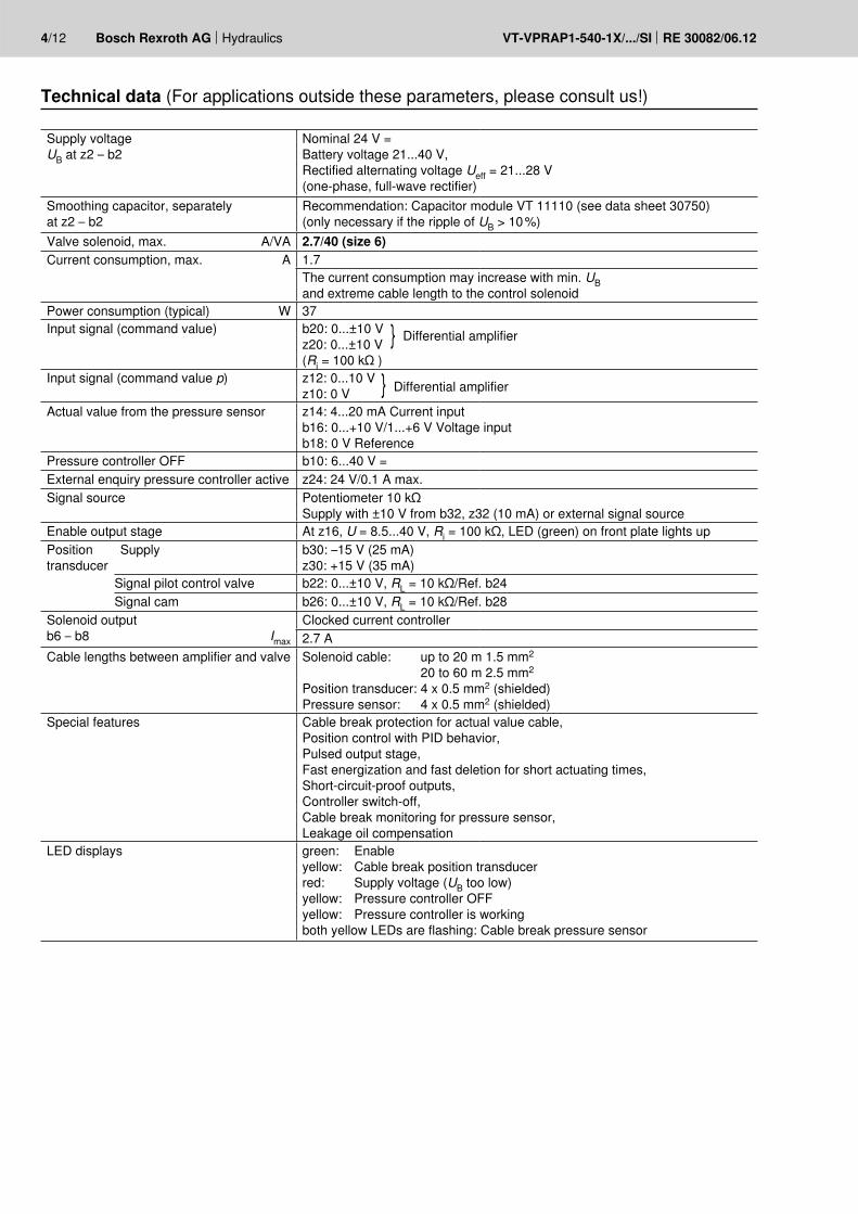
Technical data (For applications outside these parameters, please consult us!)
Supply voltageUB at z2 – b2
Nominal 24 V = Battery voltage 21...40 V, Rectified alternating voltage Ueff = 21...28 V (one-phase, full-wave rectifier)
Smoothing capacitor, separately at z2 – b2
Recommendation: Capacitor module VT 11110 (see data sheet 30750) (only necessary if the ripple of UB > 10 %)
Valve solenoid, max. A/VA 2.7/40 (size 6)Current consumption, max. A 1.7
The current consumption may increase with min. UB and extreme cable length to the control solenoid
Power consumption (typical) W 37Input signal (command value) b20: 0...±10 V
z20: 0...±10 V }Differential amplifier
(Ri = 100 kΩ )Input signal (command value p) z12: 0...10 V
z10: 0 V }Differential amplifier
Actual value from the pressure sensor z14: 4...20 mA Current input b16: 0...+10 V/1...+6 V Voltage input b18: 0 V Reference
Pressure controller OFF b10: 6...40 V =External enquiry pressure controller active z24: 24 V/0.1 A max.Signal source Potentiometer 10 kΩ
Supply with ±10 V from b32, z32 (10 mA) or external signal sourceEnable output stage At z16, U = 8.5...40 V, Ri = 100 kΩ, LED (green) on front plate lights upPosition transducer
Supply b30: –15 V (25 mA)z30: +15 V (35 mA)
Signal pilot control valve b22: 0...±10 V, RL = 10 kΩ/Ref. b24Signal cam b26: 0...±10 V, RL = 10 kΩ/Ref. b28
Solenoid output b6 – b8 Imax
Clocked current controller2.7 A
Cable lengths between amplifier and valve Solenoid cable: up to 20 m 1.5 mm2
20 to 60 m 2.5 mm2
Position transducer: 4 x 0.5 mm2 (shielded) Pressure sensor: 4 x 0.5 mm2 (shielded)
Special features Cable break protection for actual value cable, Position control with PID behavior, Pulsed output stage, Fast energization and fast deletion for short actuating times, Short-circuit-proof outputs, Controller switch-off, Cable break monitoring for pressure sensor, Leakage oil compensation
LED displays green: Enable yellow: Cable break position transducerred: Supply voltage (UB too low) yellow: Pressure controller OFF yellow: Pressure controller is working both yellow LEDs are flashing: Cable break pressure sensor
Hydraulics Bosch Rexroth AGRE 30082/06.12 VT-VPRAP1-540-1X/.../SI
UE
sU
PU
sU
A
A(B)
B(A)L
L
B
M1
X1
X2
M2 M3
PT
T
XF
B
A
P
5/12
Technical data (For applications outside these parameters, please consult us!)
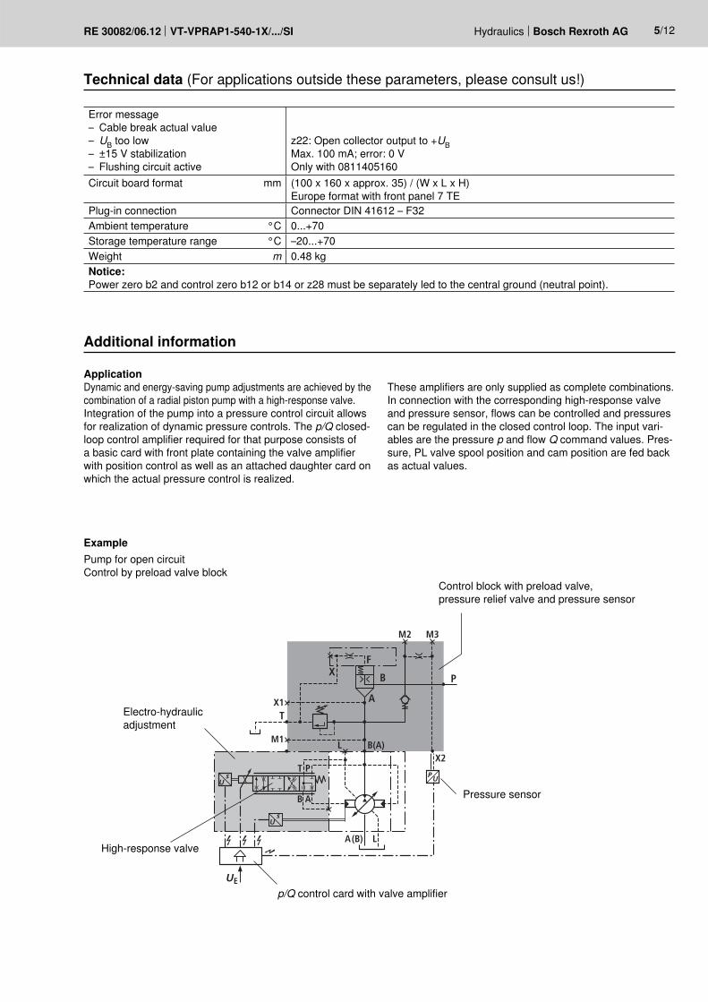
Additional information
Error message– Cable break actual value– UB too low– ±15 V stabilization– Flushing circuit active
z22: Open collector output to +UBMax. 100 mA; error: 0 V Only with 0811405160
Circuit board format mm (100 x 160 x approx. 35) / (W x L x H)Europe format with front panel 7 TE
Plug-in connection Connector DIN 41612 – F32Ambient temperature °C 0...+70Storage temperature range °C –20...+70Weight m 0.48 kgNotice:Power zero b2 and control zero b12 or b14 or z28 must be separately led to the central ground (neutral point).
ApplicationDynamic and energy-saving pump adjustments are achieved by the combination of a radial piston pump with a high-response valve. Integration of the pump into a pressure control circuit allows for realization of dynamic pressure controls. The p/Q closed-loop control amplifier required for that purpose consists of a basic card with front plate containing the valve amplifier with position control as well as an attached daughter card on which the actual pressure control is realized.
These amplifiers are only supplied as complete combinations. In connection with the corresponding high-response valve and pressure sensor, flows can be controlled and pressures can be regulated in the closed control loop. The input vari-ables are the pressure p and flow Q command values. Pres-sure, PL valve spool position and cam position are fed back as actual values.
Example Pump for open circuit Control by preload valve block
Electro-hydraulic adjustment
Control block with preload valve, pressure relief valve and pressure sensor
Pressure sensor
High-response valve
p/Q control card with valve amplifier
6/12 Bosch Rexroth AG Hydraulics VT-VPRAP1-540-1X/.../SI RE 30082/06.12
+
TV IT
KP
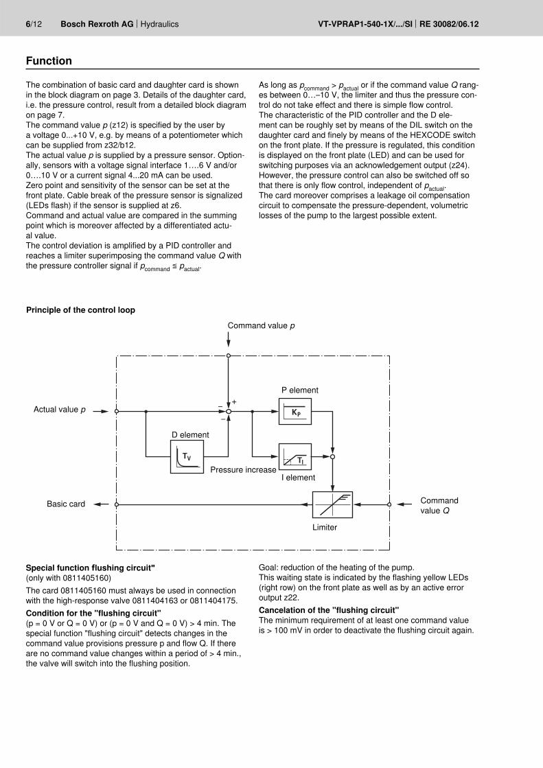
Function
The combination of basic card and daughter card is shown in the block diagram on page 3. Details of the daughter card, i.e. the pressure control, result from a detailed block diagram on page 7.The command value p (z12) is specified by the user by a voltage 0...+10 V, e.g. by means of a potentiometer which can be supplied from z32/b12.The actual value p is supplied by a pressure sensor. Option-ally, sensors with a voltage signal interface 1….6 V and/or 0….10 V or a current signal 4...20 mA can be used.Zero point and sensitivity of the sensor can be set at the front plate. Cable break of the pressure sensor is signalized (LEDs flash) if the sensor is supplied at z6.Command and actual value are compared in the summing point which is moreover affected by a differentiated actu-al value. The control deviation is amplified by a PID controller and reaches a limiter superimposing the command value Q with the pressure controller signal if pcommand ≦ pactual.
Special function flushing circuit"(only with 0811405160)The card 0811405160 must always be used in connection with the high-response valve 0811404163 or 0811404175.Condition for the "flushing circuit"(p = 0 V or Q = 0 V) or (p = 0 V and Q = 0 V) > 4 min. The special function "flushing circuit" detects changes in the command value provisions pressure p and flow Q. If there are no command value changes within a period of > 4 min., the valve will switch into the flushing position.
As long as pcommand > pactual or if the command value Q rang-es between 0…–10 V, the limiter and thus the pressure con-trol do not take effect and there is simple flow control.The characteristic of the PID controller and the D ele-ment can be roughly set by means of the DIL switch on the daughter card and finely by means of the HEXCODE switch on the front plate. If the pressure is regulated, this condition is displayed on the front plate (LED) and can be used for switching purposes via an acknowledgement output (z24). However, the pressure control can also be switched off so that there is only flow control, independent of pactual.The card moreover comprises a leakage oil compensation circuit to compensate the pressure-dependent, volumetric losses of the pump to the largest possible extent.
Goal: reduction of the heating of the pump. This waiting state is indicated by the flashing yellow LEDs (right row) on the front plate as well as by an active error output z22.Cancelation of the "flushing circuit"The minimum requirement of at least one command value is > 100 mV in order to deactivate the flushing circuit again.
Principle of the control loop
Command value p
Actual value p
Pressure increase
P element
D element
I element
Limiter
Basic card Command value Q
Hydraulics Bosch Rexroth AGRE 30082/06.12 VT-VPRAP1-540-1X/.../SI
K
+U
B
–UB
+15
V–1
5 V
L –0
V
TP3
(0 V
)
TP1
St –
0 V
3-1
3-5
1-7
z24
1-4
1-2
3-3
1-6
2-4
b10
P6 A
*z6 b3
0
b18
z14
z18
pz1
0
z12
TP2 2-
2
2-3
2-1
0 V
0...+
10 V
6...4
0 V
+15
V
DIL
4
DIL
3
DIL
5
DIL
6-10
DIL
11-1
6
–15
V
0...+
10 V
4...2
0 m
A
+ +
+
+
*
+
+
DIL
1
+
P1(Q
)
p
S3S2
S1
DIL
2
PK I
K D
Q
max
Q
Qp
,Q
p
p gai
n
p zer
o
100
k
100
k
100
k
200 Ω
1...6
V/0
...10
V
1)
2)
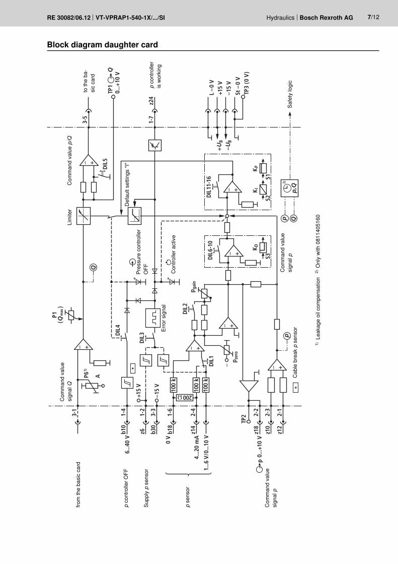
7/12
Block diagram daughter card
from
the
basi
c ca
rdto
the
ba-
sic
card
Safe
ty lo
gic
p co
ntro
ller O
FF
p co
ntro
ller
is w
orki
ng
p se
nsor
Com
man
d va
lue
sign
al p
Com
man
d va
lue
sign
al Q
Lim
iter
Com
man
d va
lue p/Q
Com
man
d va
lue
sign
al p
Supp
ly p
sen
sor
Pres
sure
con
trolle
r O
FF
Erro
r sig
nal
Con
trolle
r act
ive
Def
ault
setti
ngs
"I"
Cab
le b
reak
p s
enso
r
1) L
eaka
ge o
il co
mpe
nsat
ion
2) O
nly
with
081
1405
160
8/12 Bosch Rexroth AG Hydraulics VT-VPRAP1-540-1X/.../SI RE 30082/06.12
Mode setting (DIL switch, daughter card)
DIL no.
Status 1) Function
0 – without function 1 ON Pressure sensor
signal1...6 V/0...10 V
OFF 4...20 mA 2 ON Pressure sensor
amplificationpSYS
3) ≙ ~ pNOM4)
or mA sensorOFF pSYS
2) ≙ ~ 0.5 · pNOM 3 ON Cable break
monitoring pressure sensor
OnOFF Off
4 ON Pressure controller OnOFF Off
5 ON Valve output signal for valvesOFF for radial piston pump
6 ON
D
Pressure reduction
D share is selected by DIL 8, 9, 10
OFF DIL 8, 9, 10 without effect 7 ON Pressure build-up D share is influenced by
DIL 8, 9, 10OFF DIL 8, 9, 10 without effect
8 ON Share low (9, 10 = OFF) 9 ON Share medium (8, 10 = OFF)10 ON Share high (8, 9 = OFF)11 ON
IShare = 0
OFF Share active (KI)12 ON KI active (11 = OFF)13 ON
P
Swivel angle +10...–0.7 VOFF normal
14 ON Share low (16 = ON/15 = OFF)15 ON Share medium (14, 16 = OFF)16 ON Share high (14, 15 = OFF)
1) As-delivered state2) Application after consultation3) pSYS = System pressure4) pNOM = Nominal sensor pressure
DIL 16...0Leakage oil compensation
Hydraulics Bosch Rexroth AGRE 30082/06.12 VT-VPRAP1-540-1X/.../SI 9/12
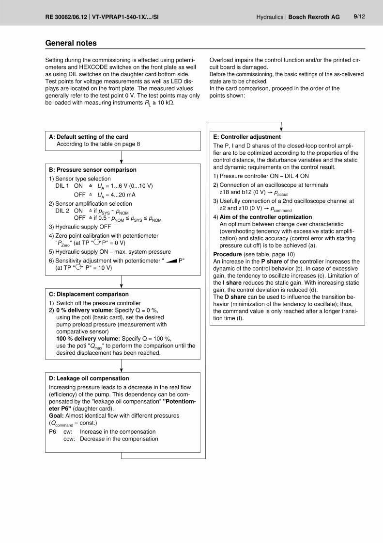
General notes
Setting during the commissioning is effected using potenti-ometers and HEXCODE switches on the front plate as well as using DIL switches on the daughter card bottom side. Test points for voltage measurements as well as LED dis-plays are located on the front plate. The measured values generally refer to the test point 0 V. The test points may only be loaded with measuring instruments RL ≧ 10 kΩ.
Overload impairs the control function and/or the printed cir-cuit board is damaged. Before the commissioning, the basic settings of the as-delivered state are to be checked. In the card comparison, proceed in the order of the points shown:
A: Default setting of the cardAccording to the table on page 8
C: Displacement comparison1) Switch off the pressure controller 2) 0 % delivery volume: Specify Q = 0 %,
using the poti (basic card), set the desired pump preload pressure (measurement with comparative sensor)100 % delivery volume: Specify Q = 100 %, use the poti "Qmax" to perform the comparison until the desired displacement has been reached.
D: Leakage oil compensationIncreasing pressure leads to a decrease in the real flow (efficiency) of the pump. This dependency can be com-pensated by the "leakage oil compensation" "Potentiom-eter P6" (daughter card).Goal: Almost identical flow with different pressures (Qcommand = const.)P6 cw: Increase in the compensation ccw: Decrease in the compensation
B: Pressure sensor comparison1) Sensor type selection
DIL 1 ON ≙ UA = 1...6 V (0...10 V) OFF ≙ UA = 4...20 mA2) Sensor amplification selection
DIL 2 ON ≙ if pSYS ~ pNOM OFF ≙ if 0.5 · pNOM ≦ pSYS ≦ pNOM
3) Hydraulic supply OFF4) Zero point calibration with potentiometer
"PZero" (at TP " P" = 0 V)5) Hydraulic supply ON – max. system pressure6) Sensitivity adjustment with potentiometer " P"
(at TP " P" = 10 V)
E: Controller adjustmentThe P, I and D shares of the closed-loop control ampli-fier are to be optimized according to the properties of the control distance, the disturbance variables and the static and dynamic requirements on the control result.1) Pressure controller ON – DIL 4 ON2) Connection of an oscilloscope at terminals
z18 and b12 (0 V) pactual3) Usefully connection of a 2nd oscilloscope channel at
z2 and z10 (0 V) pcommand4) Aim of the controller optimization
An optimum between change over characteristic (overshooting tendency with excessive static amplifi-cation) and static accuracy (control error with starting pressure cut off) is to be achieved (a).
Procedure (see table, page 10) An increase in the P share of the controller increases the dynamic of the control behavior (b). In case of excessive gain, the tendency to oscillate increases (c). Limitation of the I share reduces the static gain. With increasing static gain, the control deviation is reduced (d). The D share can be used to influence the transition be-havior (minimization of the tendency to oscillate); thus, the command value is only reached after a longer transi-tion time (f).
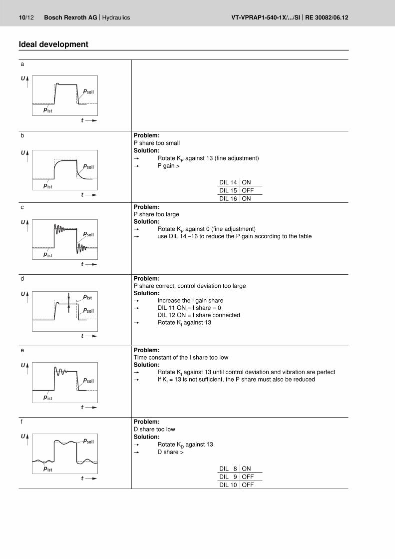
10/12 Bosch Rexroth AG Hydraulics VT-VPRAP1-540-1X/.../SI RE 30082/06.12
a
ist
soll
U
t
p
p
b
sollp
ist
U
t
p
Problem:P share too smallSolution: Rotate KP against 13 (fine adjustment) P gain >
DIL 14 ONDIL 15 OFFDIL 16 ON
c
sollp
istp
U
t
Problem:P share too largeSolution: Rotate KP against 0 (fine adjustment) use DIL 14 –16 to reduce the P gain according to the table
d
ist
soll
U
t
p
p
Problem:P share correct, control deviation too largeSolution: Increase the I gain share DIL 11 ON = I share = 0
DIL 12 ON = I share connected Rotate KI against 13
e
istp
soll
U
t
p
Problem:Time constant of the I share too lowSolution: Rotate KI against 13 until control deviation and vibration are perfect If KI = 13 is not sufficient, the P share must also be reduced
f
istp
sollU
t
p
Problem:D share too lowSolution: Rotate KD against 13 D share >
DIL 8 ONDIL 9 OFFDIL 10 OFF
Ideal development
Hydraulics Bosch Rexroth AGRE 30082/06.12 VT-VPRAP1-540-1X/.../SI 11/12
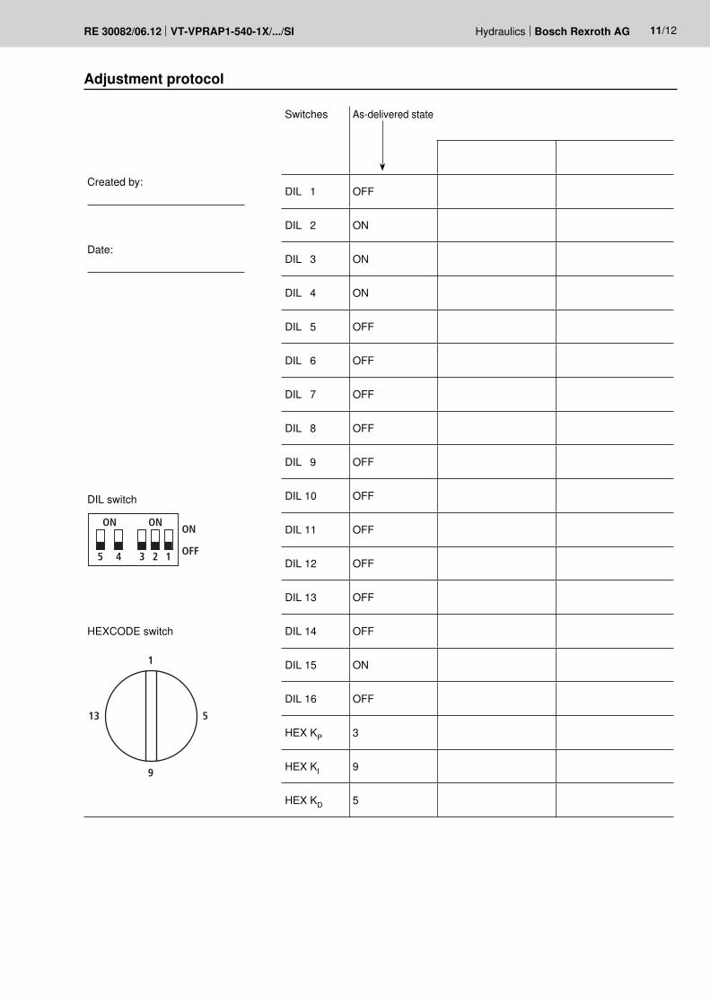
Adjustment protocol
Switches As-delivered state
Created by:
DIL 1 OFF
DIL 2 ON
Date:
DIL 3 ON
DIL 4 ON
DIL 5 OFF
DIL 6 OFF
DIL 7 OFF
DIL 8 OFF
DIL 9 OFF
DIL switch
12345
ON ONON
OFF
DIL 10 OFF
DIL 11 OFF
DIL 12 OFF
DIL 13 OFF
HEXCODE switch DIL 14 OFF
1
9
13 5
DIL 15 ON
DIL 16 OFF
HEX KP 3
HEX KI 9
HEX KD 5
12/12 Bosch Rexroth AG Hydraulics VT-VPRAP1-540-1X/.../SI RE 30082/06.12
Bosch Rexroth AG HydraulicsZum Eisengießer 197816 Lohr am Main, GermanyPhone +49 (0) 93 52 / [email protected]
© This document, as well as the data, specifications and other informa-tion set forth in it, are the exclusive property of Bosch Rexroth AG. It may not be reproduced or given to third parties without its consent.The data specified above only serve to describe the product. No state-ments concerning a certain condition or suitability for a certain applica-tion can be derived from our information. The information given does not release the user from the obligation of own judgment and verification. It must be remembered that our products are subject to a natural process of wear and aging.
35
100
24
V=
DIN 41612 - F 32
160
Unit dimensions (dimensions in mm)
Plug-in connector
Mai
ns
Project planning / maintenance instructions / additional information– The amplifier card may only be unplugged and plugged when de-energized.– The distance to aerial lines, radios and radar systems must be sufficient (> 1 m).– Do not lay solenoid and signal lines near power cables.– For signal lines and solenoid conductors, we recommend using shielded cables.
The cable shield must be connected to the control cabinet extensively and as short as possible.– The valve solenoid must not be connected to free-wheeling diodes or other protective circuits.– The cable lengths and cross-sections specified on page 4 must be complied with.
p/Q closed-loop control amplifier
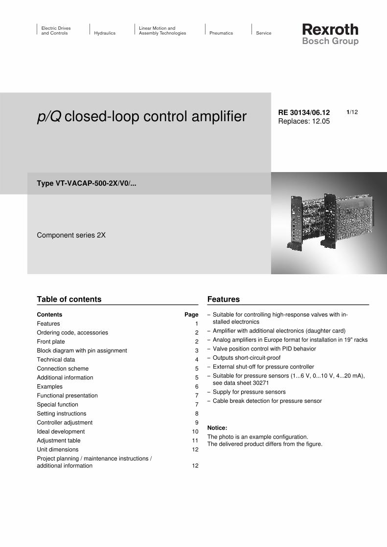
Type VT-VACAP-500-2X/V0/...
Component series 2X
RE 30134/06.12Replaces: 12.05
Table of contentsContents PageFeatures 1Ordering code, accessories 2Front plate 2Block diagram with pin assignment 3Technical data 4Connection scheme 5Additional information 5Examples 6Functional presentation 7Special function 7Setting instructions 8Controller adjustment 9Ideal development 10Adjustment table 11Unit dimensions 12Project planning / maintenance instructions / additional information 12
Features– Suitable for controlling high-response valves with in-
stalled electronics– Amplifier with additional electronics (daughter card) – Analog amplifiers in Europe format for installation in 19" racks– Valve position control with PID behavior– Outputs short-circuit-proof– External shut-off for pressure controller– Suitable for pressure sensors (1...6 V, 0...10 V, 4...20 mA),
see data sheet 30271– Supply for pressure sensors– Cable break detection for pressure sensor
Notice:The photo is an example configuration. The delivered product differs from the figure.
1/12
ON
+–
+–
0 V
1 2Q
Regleroff
P
Q=0
+–
+– Pnull
ist
Pist
KP
KI
KD
max
2/12 Bosch Rexroth AG Hydraulics VT-VACAP-500-2X/V0/... RE 30134/06.12
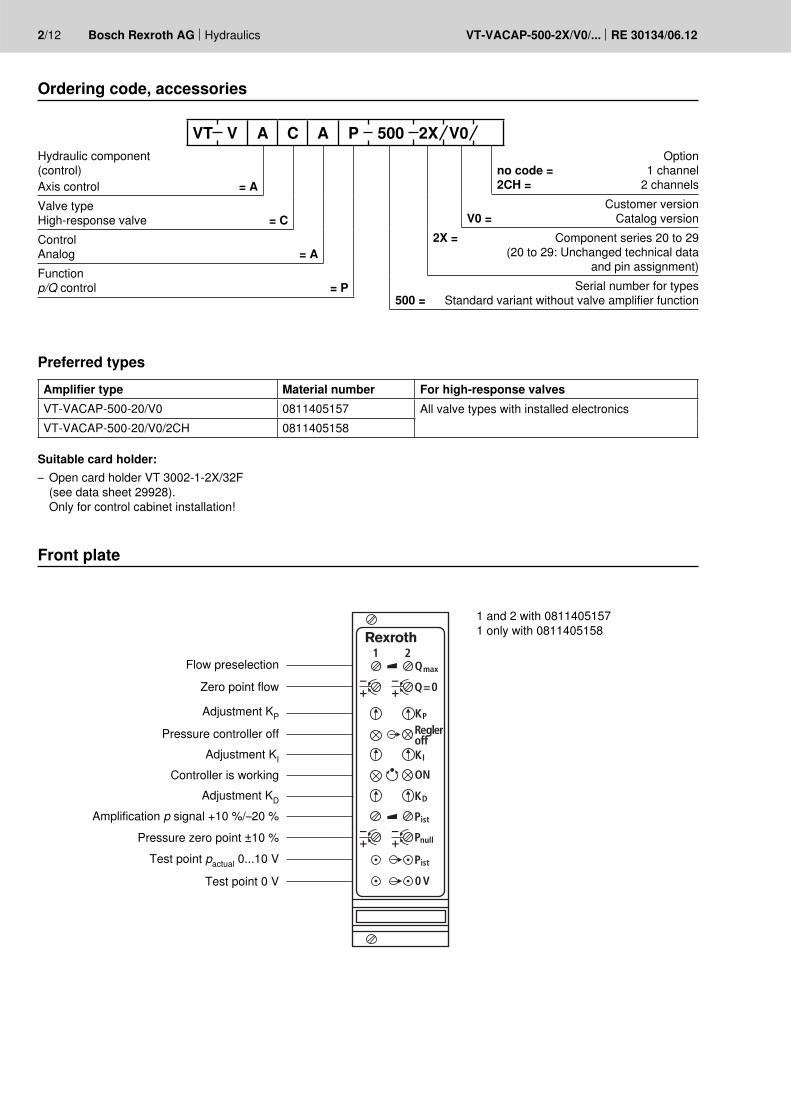
Ordering code, accessories
Front plate
Preferred typesAmplifier type Material number For high-response valvesVT-VACAP-500-20/V0 0811405157 All valve types with installed electronicsVT-VACAP-500-20/V0/2CH 0811405158
Hydraulic component(control)Axis control = AValve type High-response valve = CControl Analog = AFunctionp/Q control = P
Optionno code = 1 channel2CH = 2 channels
Customer versionV0 = Catalog version
2X = Component series 20 to 29 (20 to 29: Unchanged technical data
and pin assignment)Serial number for types
500 = Standard variant without valve amplifier function
Flow preselection
Zero point flow
Adjustment KP
Pressure controller offAdjustment KI
Controller is workingAdjustment KD
Amplification p signal +10 %/–20 %
Pressure zero point ±10 %Test point pactual 0...10 V
Test point 0 V
1 and 2 with 08114051571 only with 0811405158
VT V A C A P 500 2X V0
Suitable card holder: – Open card holder VT 3002-1-2X/32F
(see data sheet 29928). Only for control cabinet installation!
+10 V
+15 V0 V
–15 V
b2
b8
0…10 V
6…40 V
0…10 V
4…20 mA
UAI
0 V
0 V
24 V
0 V
15 V/100 mA
0 V0 V
zero“ ON”
b10
P soll
Qsoll
1...6 V/0...10 V
z12z10z20b20
z4
b2
b18
b16
z2
z24
z18
z14
PID
S5/S6
DIL4
DIL3 AMV
AMV
DIL5 IIU U
DIL1
off
24 V
Tp
Tp4 Tp5
DIL2
DIL0
DC
DC
UB
“ ON”
5 %+
z6
z30
z32
b32
b4 (D)
(E)
UAll(D)
(E)
No
b8
0…10 V
6…40 V
6…40 V
0…10 V
4…20 mA
24 V/20 mA
24 V/20 mA
0 V
0 V
0… 10 V
10 V
0 V0 V
zero“ ON”
z28
P soll
Qsoll
1...6 V/0...10 V
b12b14z22b22
b28
b26
z26
z16
b24
PID
S5/S6
DIL4
DIL3
DIL5 IIU U
DIL1
off
24 V
Tp
Tp4 Tp5
DIL2
“ ON”
5 %+
+
0… 10 V+
b30
1
Qmax
Q = 0
Qmax
Q = 0
pist
pnull
pist
pnull
Hydraulics Bosch Rexroth AGRE 30134/06.12 VT-VACAP-500-2X/V0/... 3/12
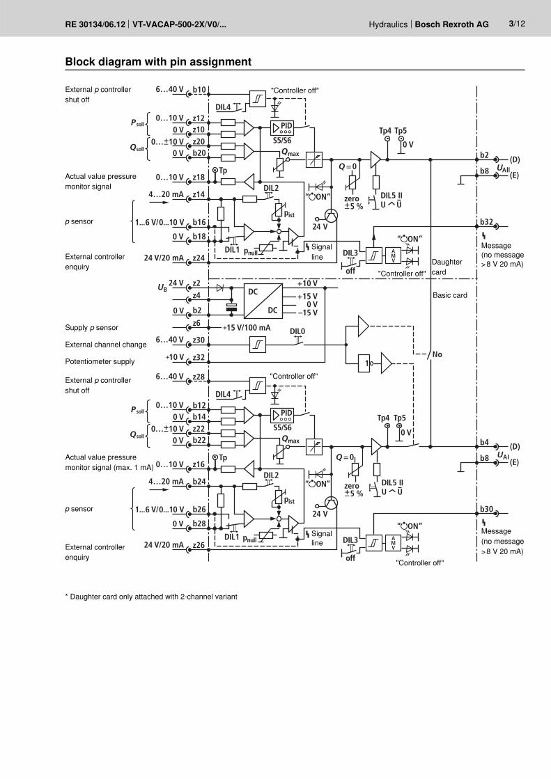
Block diagram with pin assignment
External p controller shut off
External p controller shut off
Supply p sensor
Potentiometer supply
External controller enquiry
External controller enquiry
* Daughter card only attached with 2-channel variant
External channel change
p sensor
p sensor
Actual value pressure monitor signal
Actual value pressure monitor signal (max. 1 mA)
"Controller off"
"Controller off"
"Controller off"
"Controller off"
Signal line
Signal line Daughter
card
Message (no message > 8 V 20 mA)
Message (no message > 8 V 20 mA)
Basic card
4/12 Bosch Rexroth AG Hydraulics VT-VACAP-500-2X/V0/... RE 30134/06.12
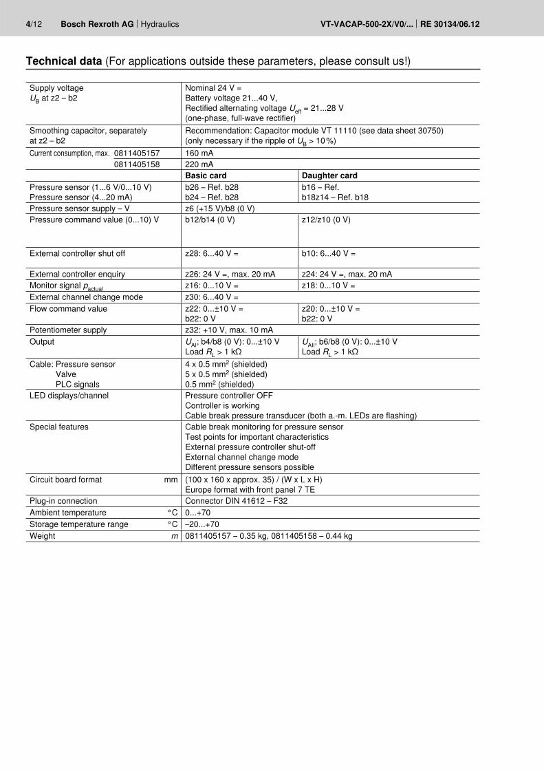
Technical data (For applications outside these parameters, please consult us!)
Supply voltageUB at z2 – b2
Nominal 24 V = Battery voltage 21...40 V, Rectified alternating voltage Ueff = 21...28 V (one-phase, full-wave rectifier)
Smoothing capacitor, separately at z2 – b2
Recommendation: Capacitor module VT 11110 (see data sheet 30750) (only necessary if the ripple of UB > 10 %)
Current consumption, max. 0811405157 160 mA0811405158 220 mA
Basic card Daughter cardPressure sensor (1...6 V/0...10 V) Pressure sensor (4...20 mA)
b26 – Ref. b28b24 – Ref. b28
b16 – Ref. b18z14 – Ref. b18
Pressure sensor supply – V z6 (+15 V)/b8 (0 V)Pressure command value (0...10) V b12/b14 (0 V) z12/z10 (0 V)
External controller shut off z28: 6...40 V = b10: 6...40 V =
External controller enquiry z26: 24 V =, max. 20 mA z24: 24 V =, max. 20 mAMonitor signal pactual z16: 0...10 V = z18: 0...10 V =External channel change mode z30: 6...40 V =Flow command value z22: 0...±10 V =
b22: 0 V z20: 0...±10 V =b22: 0 V
Potentiometer supply z32: +10 V, max. 10 mAOutput UAI; b4/b8 (0 V): 0...±10 V
Load RL > 1 kΩUAIl; b6/b8 (0 V): 0...±10 V Load RL > 1 kΩ
Cable: Pressure sensor Valve PLC signals
4 x 0.5 mm2 (shielded) 5 x 0.5 mm2 (shielded) 0.5 mm2 (shielded)
LED displays/channel Pressure controller OFF Controller is working Cable break pressure transducer (both a.-m. LEDs are flashing)
Special features Cable break monitoring for pressure sensor Test points for important characteristics External pressure controller shut-off External channel change mode Different pressure sensors possible
Circuit board format mm (100 x 160 x approx. 35) / (W x L x H)Europe format with front panel 7 TE
Plug-in connection Connector DIN 41612 – F32Ambient temperature °C 0...+70Storage temperature range °C –20...+70Weight m 0811405157 – 0.35 kg, 0811405158 – 0.44 kg
UB
24 V DC
pU
0 V
z.B.
4/3 WV + Pilot
4/4 WV – NG105/3 WV – NG10
4/4 WV – NG63/2 WV (Cartr.) + Pilot
b18b8
Isig
Usup z6
z14
0 V/
0 V
0 V/P PP
UI Ub18b8
Usig
Usup z6
b8
sig
sig
U
supU z6b2
b16b16
b18
Hydraulics Bosch Rexroth AGRE 30134/06.12 VT-VACAP-500-2X/V0/... 5/12
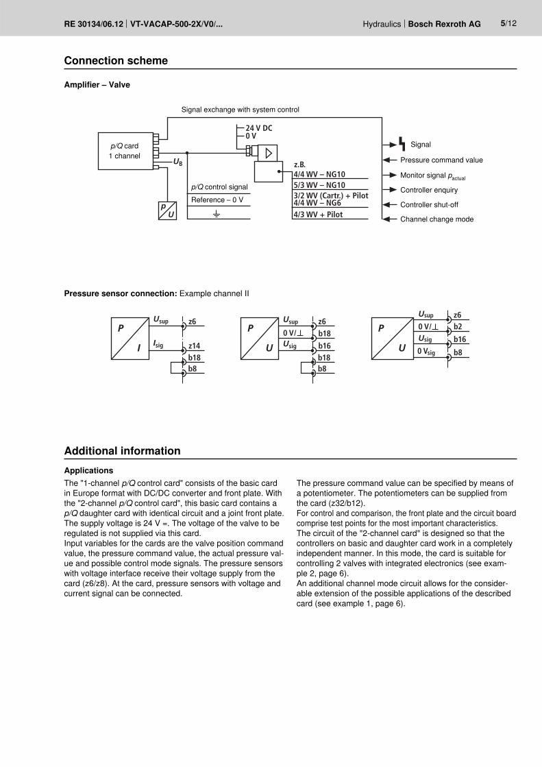
Connection scheme
Additional information
Amplifier – Valve
ApplicationsThe "1-channel p/Q control card" consists of the basic card in Europe format with DC/DC converter and front plate. With the "2-channel p/Q control card", this basic card contains a p/Q daughter card with identical circuit and a joint front plate. The supply voltage is 24 V =. The voltage of the valve to be regulated is not supplied via this card. Input variables for the cards are the valve position command value, the pressure command value, the actual pressure val-ue and possible control mode signals. The pressure sensors with voltage interface receive their voltage supply from the card (z6/z8). At the card, pressure sensors with voltage and current signal can be connected.
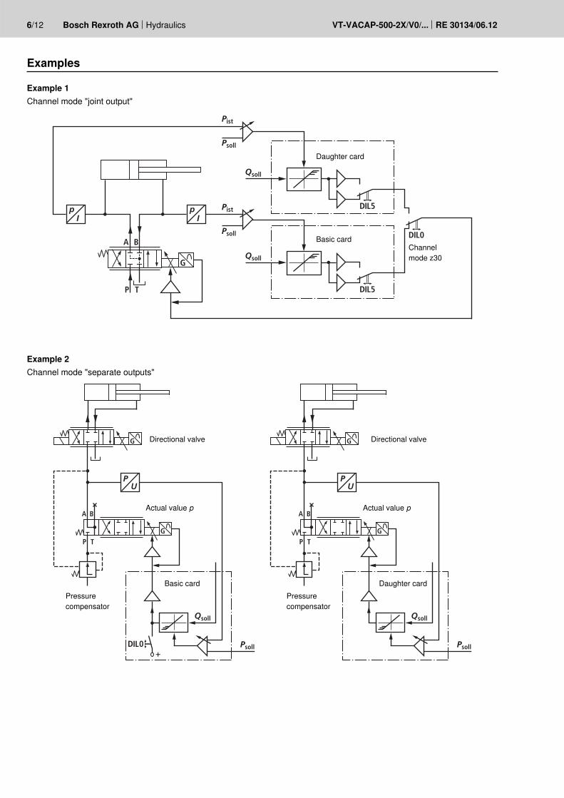
The pressure command value can be specified by means of a potentiometer. The potentiometers can be supplied from the card (z32/b12). For control and comparison, the front plate and the circuit board comprise test points for the most important characteristics. The circuit of the "2-channel card" is designed so that the controllers on basic and daughter card work in a completely independent manner. In this mode, the card is suitable for controlling 2 valves with integrated electronics (see exam-ple 2, page 6). An additional channel mode circuit allows for the consider-able extension of the possible applications of the described card (see example 1, page 6).
Pressure sensor connection: Example channel II
Signal exchange with system control
Pressure command value
Monitor signal pactual
Controller enquiry
Controller shut-off
Channel change mode
p/Q card 1 channel
p/Q control signalReference – 0 V
Signal
A B
P
p
T
G
Ip
IDIL5
DIL5
DIL0
Qsoll
Psoll
Pist
Psoll
Pist
Qsoll
A B
P T
G
P PU
G
DIL0+
Psoll
Qsoll
A B
P T
G
U
G
Psoll
Qsoll
6/12 Bosch Rexroth AG Hydraulics VT-VACAP-500-2X/V0/... RE 30134/06.12
Examples
Example 1Channel mode "joint output"
Example 2Channel mode "separate outputs"
Daughter card
Basic card
Basic card Daughter card
Directional valve Directional valve
Actual value p Actual value p
Pressure compensator
Pressure compensator
Channel mode z30
z30
DIL0 No
Nc
1
Hydraulics Bosch Rexroth AGRE 30134/06.12 VT-VACAP-500-2X/V0/... 7/12
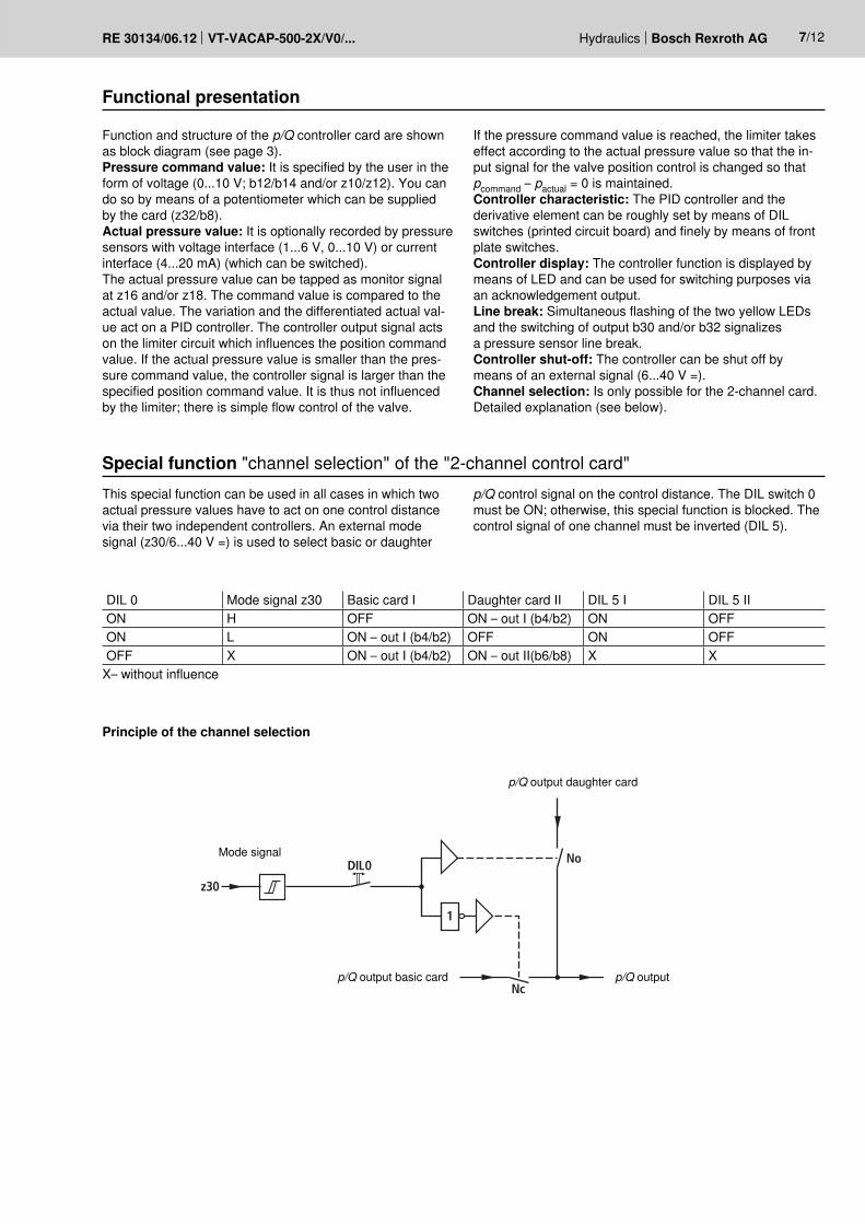
Functional presentation
Special function "channel selection" of the "2-channel control card"
DIL 0 Mode signal z30 Basic card I Daughter card II DIL 5 I DIL 5 IION H OFF ON – out I (b4/b2) ON OFFON L ON – out I (b4/b2) OFF ON OFFOFF X ON – out I (b4/b2) ON – out II(b6/b8) X X
X– without influence
Function and structure of the p/Q controller card are shown as block diagram (see page 3).Pressure command value: It is specified by the user in the form of voltage (0...10 V; b12/b14 and/or z10/z12). You can do so by means of a potentiometer which can be supplied by the card (z32/b8).Actual pressure value: It is optionally recorded by pressure sensors with voltage interface (1...6 V, 0...10 V) or current interface (4...20 mA) (which can be switched). The actual pressure value can be tapped as monitor signal at z16 and/or z18. The command value is compared to the actual value. The variation and the differentiated actual val-ue act on a PID controller. The controller output signal acts on the limiter circuit which influences the position command value. If the actual pressure value is smaller than the pres-sure command value, the controller signal is larger than the specified position command value. It is thus not influenced by the limiter; there is simple flow control of the valve.
This special function can be used in all cases in which two actual pressure values have to act on one control distance via their two independent controllers. An external mode signal (z30/6...40 V =) is used to select basic or daughter
Principle of the channel selection
If the pressure command value is reached, the limiter takes effect according to the actual pressure value so that the in-put signal for the valve position control is changed so that pcommand – pactual = 0 is maintained.Controller characteristic: The PID controller and the derivative element can be roughly set by means of DIL switches (printed circuit board) and finely by means of front plate switches.Controller display: The controller function is displayed by means of LED and can be used for switching purposes via an acknowledgement output.Line break: Simultaneous flashing of the two yellow LEDs and the switching of output b30 and/or b32 signalizes a pressure sensor line break.Controller shut-off: The controller can be shut off by means of an external signal (6...40 V =).Channel selection: Is only possible for the 2-channel card. Detailed explanation (see below).
p/Q control signal on the control distance. The DIL switch 0 must be ON; otherwise, this special function is blocked. The control signal of one channel must be inverted (DIL 5).
Mode signal
p/Q output daughter card
p/Q outputp/Q output basic card
8/12 Bosch Rexroth AG Hydraulics VT-VACAP-500-2X/V0/... RE 30134/06.12
Setting instructions
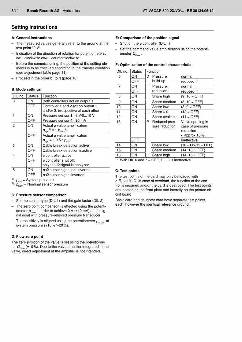
A: General instructions– The measured values generally refer to the ground at the
test point "0 V"– Indication of the direction of rotation for potentiometers:
cw – clockwise ccw – counterclockwise– Before the commissioning, the position of the setting ele-
ments is to be checked according to the transfer condition (see adjustment table page 11)
– Proceed in the order b) to f) (page 10).
B: Mode settingsDIL no. Status Function0 ON Both controllers act on output 1
OFF Controller 1 and 2 act on output 1 and/or 2, irrespective of each other
1 ON Pressure sensor 1...6 V/0...10 VOFF Pressure sensor 4...20 mA
2 ON Actual p value amplificationpsys
1) ≙ ~ pnom2)
OFF Actual p value amplificationpsys ≙ ~ 0.5 • pnom
3 ON Cable break detection activeOFF Cable break detection inactive
4 ON p controller activeOFF p controller shut off,
only the Q signal is analyzed5 ON p/Q output signal not inverted
OFF p/Q output signal inverted1) psys = System pressure2) pnom = Nominal sensor pressure
C: Pressure sensor comparison– Set the sensor type (DIL 1) and the gain factor (DIL 2)– The zero point comparison is effected using the potenti-
ometer pzero in order to achieve 0 V (±10 mV) at the sig-nal input with pressure-relieved pressure transducer
– The sensitivity is aligned using the potentiometer pactual at system pressure (+10 % / –20 %).
D: Flow zero pointThe zero position of the valve is set using the potentiome-ter Qzero (±10 %). Due to the valve amplifier integrated in the valve, direct adjustment at the amplifier is not intended.
E: Comparison of the position signal– Shut off the p controller (DIL 4)– Set the command value amplification using the potenti-
ometer Qmax..
F: Optimization of the control characteristicDIL no. Status Function 6 ON D Pressure
build-upnormal
OFF reduced 1)
7 ON Pressure reduction
normalOFF reduced 1)
8 ON Share high (9, 10 = OFF) 9 ON Share medium (8, 10 = OFF)10 ON Share low (8, 9 = OFF)11 ON I Share = 0 (12 = OFF)12 ON Share available (11 = OFF)13 ON P Reduced pres-
sure reductionValve opening in case of pressure reduction < approx.15 %
OFF ineffective14 ON Share low (16 = ON/15 = OFF)15 ON Share medium (14, 16 = OFF)16 ON Share high (14, 15 = OFF)
1) With DIL 6 and 7 = OFF, DIL 8 is ineffective
G: Test pointsThe test points of the card may only be loaded with a RL > 10 kΩ. in case of overload, the function of the con-trol is impaired and/or the card is destroyed. The test points are located on the front plate and laterally on the printed cir-cuit board.Basic card and daughter card have separate test points each, however the identical reference ground.
Hydraulics Bosch Rexroth AGRE 30134/06.12 VT-VACAP-500-2X/V0/... 9/12
Controller adjustment
The P, I and D shares of the closed-loop control amplifier are to be optimized according to the properties of the control distance, the disturbance variables and the static and dy-namic requirements on the control result.1) Pressure controller ON – DIL 4 ON2) Connection of an oscilloscope at the test point "pactual"3) Usefully connection of a 2nd oscilloscope channel at the
terminals "pcommand"4) DIL 6 and DIL 7 serve to compensate dynamic differenc-
es in the pressure build-up and reduction in the system DIL 6 ON = Normal application OFF = Special application DIL 7 ON = Normal application OFF = Special application
5) DIL 13 reduces the pressure reduction by means of a max. valve opening < approx. 15 % ON = Special application OFF = Normal application
6) Aim of the controller optimizationAn optimum between change over characteristic (overshoot-ing tendency with excessive static amplification) and static accuracy (control error with starting pressure cut off) is to be achieved (a).
Procedure (see table, page 11): An increase in the P share of the controller increases the dynamic of the control behavior (b). In case of excessive gain, the tendency to oscillate increases (c). Limitation of the I share reduces the static gain. With in-creasing static gain, the control deviation is reduced (d). The D share can be used to influence the transition behavior (minimization of the tendency to oscillate); thus, the com-mand value is only reached after a longer transition time (f).
10/12 Bosch Rexroth AG Hydraulics VT-VACAP-500-2X/V0/... RE 30134/06.12
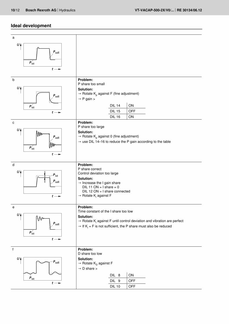
Ideal development
a
ist
soll
U
t
P
P
b
ist
soll
P
P
U
t
Problem:P share too smallSolution:→ Rotate Kp against F (fine adjustment)→ P gain >
DIL 14 ONDIL 15 OFFDIL 16 ON
c
ist
soll
P
P
U
t
Problem:P share too largeSolution:→ Rotate Kp against 0 (fine adjustment)→ use DIL 14–16 to reduce the P gain according to the table
d
istP
sollP
U
t
Problem:P share correct Control deviation too largeSolution:→ Increase the I gain share DIL 11 ON = I share = 0 DIL 12 ON = I share connected→ Rotate Ki against F
e
ist
soll
P
P
U
t
Problem:Time constant of the I share too lowSolution:→ Rotate Ki against F until control deviation and vibration are perfect→ If Ki = F is not sufficient, the P share must also be reduced
f
istP
sollPU
t
Problem:D share too lowSolution:→ Rotate KD against F→ D share >
DIL 8 ONDIL 9 OFFDIL 10 OFF
1
9
D 512345
ON ONON
OFF
Hydraulics Bosch Rexroth AGRE 30134/06.12 VT-VACAP-500-2X/V0/... 11/12
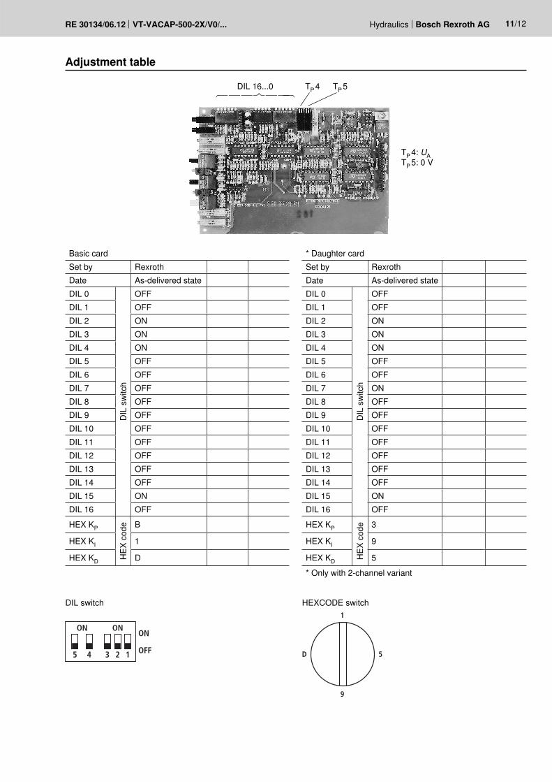
Adjustment table
Basic cardSet by RexrothDate As-delivered stateDIL 0
DIL
sw
itch
OFFDIL 1 OFFDIL 2 ONDIL 3 ONDIL 4 ONDIL 5 OFFDIL 6 OFFDIL 7 OFFDIL 8 OFFDIL 9 OFFDIL 10 OFFDIL 11 OFFDIL 12 OFFDIL 13 OFFDIL 14 OFFDIL 15 ONDIL 16 OFF
HEX KP
HEX
cod
e B
HEX KI 1
HEX KD D
* Daughter cardSet by RexrothDate As-delivered stateDIL 0
DIL
sw
itch
OFFDIL 1 OFFDIL 2 ONDIL 3 ONDIL 4 ONDIL 5 OFFDIL 6 OFFDIL 7 ONDIL 8 OFFDIL 9 OFFDIL 10 OFFDIL 11 OFFDIL 12 OFFDIL 13 OFFDIL 14 OFFDIL 15 ONDIL 16 OFF
HEX KP
HEX
cod
e 3
HEX KI 9
HEX KD 5
* Only with 2-channel variant
DIL switch
TP 4: UATP 5: 0 V
TP 4 DIL 16...0 TP 5
HEXCODE switch
35
100
24
V=
DIN 41612 - F 32
160
12/12 Bosch Rexroth AG Hydraulics VT-VACAP-500-2X/V0/... RE 30134/06.12
Bosch Rexroth AG HydraulicsZum Eisengießer 197816 Lohr am Main, GermanyPhone +49 (0) 93 52 / [email protected]
© This document, as well as the data, specifications and other informa-tion set forth in it, are the exclusive property of Bosch Rexroth AG. It may not be reproduced or given to third parties without its consent.The data specified above only serve to describe the product. No state-ments concerning a certain condition or suitability for a certain applica-tion can be derived from our information. The information given does not release the user from the obligation of own judgment and verification. It must be remembered that our products are subject to a natural process of wear and aging.
Unit dimensions (dimensions in mm)
Plug-in connector
Mai
ns
Project planning / maintenance instructions / additional information– The amplifier card may only be unplugged and plugged when de-energized.– The distance to aerial lines, radios and radar systems must be sufficient (> 1 m).– Do not lay solenoid and signal lines near power cables.– For signal lines and solenoid conductors, we recommend using shielded cables.
The cable shield must be connected to the control cabinet extensively and as short as possible.– The valve solenoid must not be connected to free-wheeling diodes or other protective circuits.– The cable lengths and cross-sections specified on page 4 must be complied with.
Industrial Electric Drives Linear Motion and Service MobileHydraulics and Controls Assembly Technologies Pneumatics Automation Hydraulics
1 819 929 097/01.03UBY 013/124
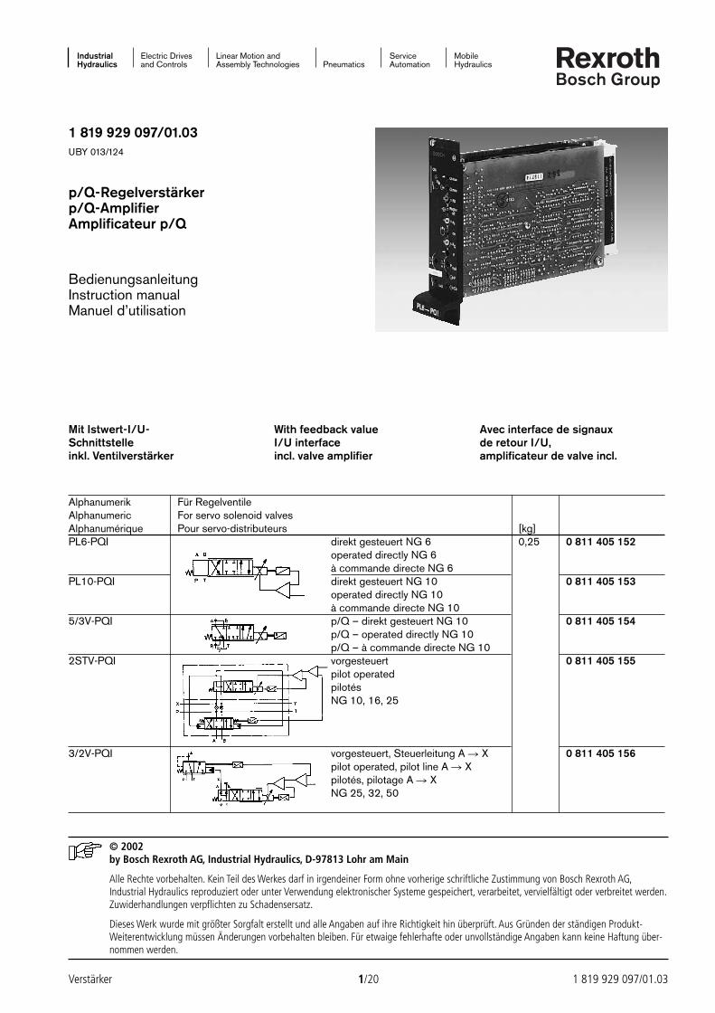
p/Q-Regelverstärkerp/Q-AmplifierAmplificateur p/Q
BedienungsanleitungInstruction manualManuel d’utilisation
© 2002by Bosch Rexroth AG, Industrial Hydraulics, D-97813 Lohr am Main
Alle Rechte vorbehalten. Kein Teil des Werkes darf in irgendeiner Form ohne vorherige schriftliche Zustimmung von Bosch Rexroth AG,Industrial Hydraulics reproduziert oder unter Verwendung elektronischer Systeme gespeichert, verarbeitet, vervielfältigt oder verbreitet werden.Zuwiderhandlungen verpflichten zu Schadensersatz.
Dieses Werk wurde mit größter Sorgfalt erstellt und alle Angaben auf ihre Richtigkeit hin überprüft. Aus Gründen der ständigen Produkt-Weiterentwicklung müssen Änderungen vorbehalten bleiben. Für etwaige fehlerhafte oder unvollständige Angaben kann keine Haftung über-nommen werden.
Verstärker 1/20 1 819 929 097/01.03
Alphanumerik Für RegelventileAlphanumeric For servo solenoid valvesAlphanumérique Pour servo-distributeurs [kg]PL6-PQI direkt gesteuert NG 6 0,25 0 811 405 152
operated directly NG 6à commande directe NG 6
PL10-PQI direkt gesteuert NG 10 0 811 405 153operated directly NG 10à commande directe NG 10
5/3V-PQI p/Q – direkt gesteuert NG 10 0 811 405 154p/Q – operated directly NG 10p/Q – à commande directe NG 10
2STV-PQI vorgesteuert 0 811 405 155pilot operated pilotésNG 10, 16, 25
3/2V-PQI vorgesteuert, Steuerleitung A X 0 811 405 156pilot operated, pilot line A Xpilotés, pilotage A XNG 25, 32, 50
Mit Istwert-I/U-Schnittstelleinkl. Ventilverstärker
With feedback valueI/U interfaceincl. valve amplifier
Avec interface de signauxde retour I/U,amplificateur de valve incl.
24388_4030_001-020 25.02.2003 8:54 Uhr Seite 1
1 819 929 097/01.03 2/20 Verstärker
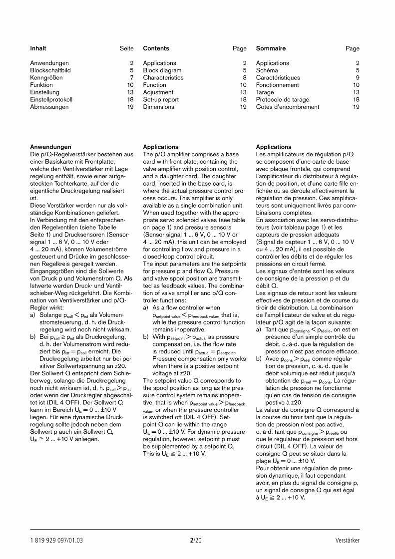
Inhalt Seite
Anwendungen 2Blockschaltbild 5Kenngrößen 7Funktion 10Einstellung 13Einstellprotokoll 18Abmessungen 19
Contents Page
Applications 2Block diagram 5Characteristics 8Function 10Adjustment 13Set-up report 18Dimensions 19
Sommaire Page
Applications 2Schéma 5Caractéristiques 9Fonctionnement 10Tarage 13Protocole de tarage 18Cotés d’encombrement 19
AnwendungenDie p/Q-Regelverstärker bestehen auseiner Basiskarte mit Frontplatte,welche den Ventilverstärker mit Lage-regelung enthält, sowie einer aufge-steckten Tochterkarte, auf der dieeigentliche Druckregelung realisiertist.Diese Verstärker werden nur als voll-ständige Kombinationen geliefert.In Verbindung mit den entsprechen-den Regelventilen (siehe Tabelle Seite 1) und Drucksensoren (Sensor-signal 1 ... 6 V, 0 ... 10 V oder 4 ... 20 mA), können Volumenströmegesteuert und Drücke im geschlosse-nen Regelkreis geregelt werden.Eingangsgrößen sind die Sollwertevon Druck p und Volumenstrom Q. AlsIstwerte werden Druck- und Ventil-schieber-Weg rückgeführt. Die Kombi-nation von Ventilverstärker und p/Q-Regler wirkt:a) Solange psoll < pist als Volumen-
stromsteuerung, d. h. die Druck-regelung wird noch nicht wirksam.
b) Bei psoll ≥ pist als Druckregelung,d. h. der Volumenstrom wird redu-ziert bis pist = psoll erreicht. DieDruckregelung arbeitet nur bei po-sitiver Sollwertspannung an z20.
Der Sollwert Q entspricht dem Schie-berweg, solange die Druckregelungnoch nicht wirksam ist, d. h. psoll > pist
oder wenn der Druckregler abgeschal-tet ist (DIL 4 OFF). Der Sollwert Qkann im Bereich UE = 0 ... ±10 Vliegen. Für eine dynamische Druck-regelung sollte jedoch neben demSollwert p auch ein Sollwert Q, UE 2 ... +10 V anliegen.
ApplicationsThe p/Q amplifier comprises a basecard with front plate, containing thevalve amplifier with position control,and a daughter card. The daughtercard, inserted in the base card, iswhere the actual pressure control pro-cess occurs. This amplifier is onlyavailable as a single combination unit.When used together with the appro-priate servo solenoid valves (see tableon page 1) and pressure sensors(Sensor signal 1 ... 6 V, 0 ... 10 V or4 ... 20 mA), this unit can be employedfor controlling flow and pressure in aclosed-loop control circuit.The input parameters are the setpointsfor pressure p and flow Q. Pressureand valve spool position are transmit-ted as feedback values. The combina-tion of valve amplifier and p/Q con-troller functions:a) As a flow controller when
psetpoint value < pfeedback value, that is,while the pressure control functionremains inoperative.
b) With psetpoint > pactual as pressurecompensation, i.e. the flow rate is reduced until pactual = psetpoint.Pressure compensation only workswhen there is a positive setpointvoltage at z20.
The setpoint value Q corresponds tothe spool position as long as the pres-sure control system remains inopera-tive, that is when psetpoint value > pfeedback
value, or when the pressure controller is switched off (DIL 4 OFF). Set-point Q can lie within the range UE = 0 ... ±10 V. For dynamic pressureregulation, however, setpoint p mustbe supplemented by a setpoint Q.This is UE 2 ... +10 V.
ApplicationsLes amplificateurs de régulation p/Qse composent d’une carte de baseavec plaque frontale, qui comprendl’amplificateur du distributeur à régula-tion de position, et d’une carte fille en-fichée où se déroule effectivement larégulation de pression. Ces amplifica-teurs sont uniquement livrés par com-binaisons complètes.En association avec les servo-distribu-teurs (voir tableau page 1) et lescapteurs de pression adéquats(Signal de capteur 1 ... 6 V, 0 ... 10 Vou 4 ... 20 mA), il est possible decontrôler les débits et de réguler lespressions en circuit fermé.Les signaux d’entrée sont les valeursde consigne de la pression p et dudébit Q.Les signaux de retour sont les valeurseffectives de pression et de course dutiroir de distribution. La combinaisonde l’amplificateur de valve et du régu-lateur p/Q agit de la façon suivante:a) Tant que pconsigne < préelle, on est en
présence d’un simple contrôle dudébit, c.-à-d. que la régulation depression n’est pas encore efficace.
b) Avec pcons > préel comme régula-tion de pression, c.-à.-d. que ledébit volumique est réduit jusqu’àobtention de préel = pcons. La régu-lation de pression ne fonctionnequ’en cas de tension de consignepostive à z20.
La valeur de consigne Q correspond àla course du tiroir tant que la régula-tion de pression n’est pas active, c.-à-d. tant que pconsigne > préelle ou que le régulateur de pression est horscircuit (DIL 4 OFF). La valeur deconsigne Q peut se situer dans laplage UE = 0 ... ±10 V.Pour obtenir une régulation de pres-sion dynamique, il faut cependantavoir, en plus du signal de consigne p,un signal de consigne Q qui est égal à UE 2 ... +10 V.
24388_4030_001-020 25.02.2003 8:54 Uhr Seite 2
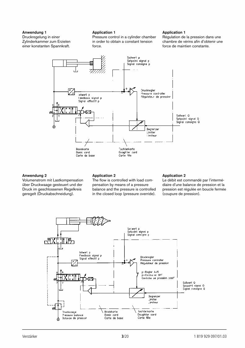
Verstärker 3/20 1 819 929 097/01.03
Anwendung 1Druckregelung in einerZylinderkammer zum Erzielen einer konstanten Spannkraft.
Application 1Pressure control in a cylinder chamberin order to obtain a constant tensionforce.
Application 1Régulation de la pression dans unechambre de vérins afin d’obtenir uneforce de maintien constante.
Anwendung 2Volumenstrom mit Lastkompensationüber Druckwaage gesteuert und derDruck im geschlossenen Regelkreisgeregelt (Druckabschneidung).
Application 2The flow is controlled with load com-pensation by means of a pressurebalance and the pressure is controlledin the closed loop (pressure override).
Application 2Le débit est commandé par l’intermé-diaire d’une balance de pression et lapression est régulée en boucle fermée(coupure de pression).
24388_4030_001-020 25.02.2003 8:54 Uhr Seite 3
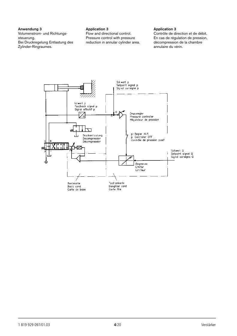
1 819 929 097/01.03 4/20 Verstärker
Anwendung 3Volumenstrom- und Richtungs-steuerung.Bei Druckregelung Entlastung desZylinder-Ringraumes.
Application 3Flow and directional control.Pressure control with pressurereduction in annular cylinder area.
Application 3Contrôle de direction et de débit.En cas de régulation de pression,décompression de la chambreannulaire du vérin.
24388_4030_001-020 25.02.2003 8:54 Uhr Seite 4
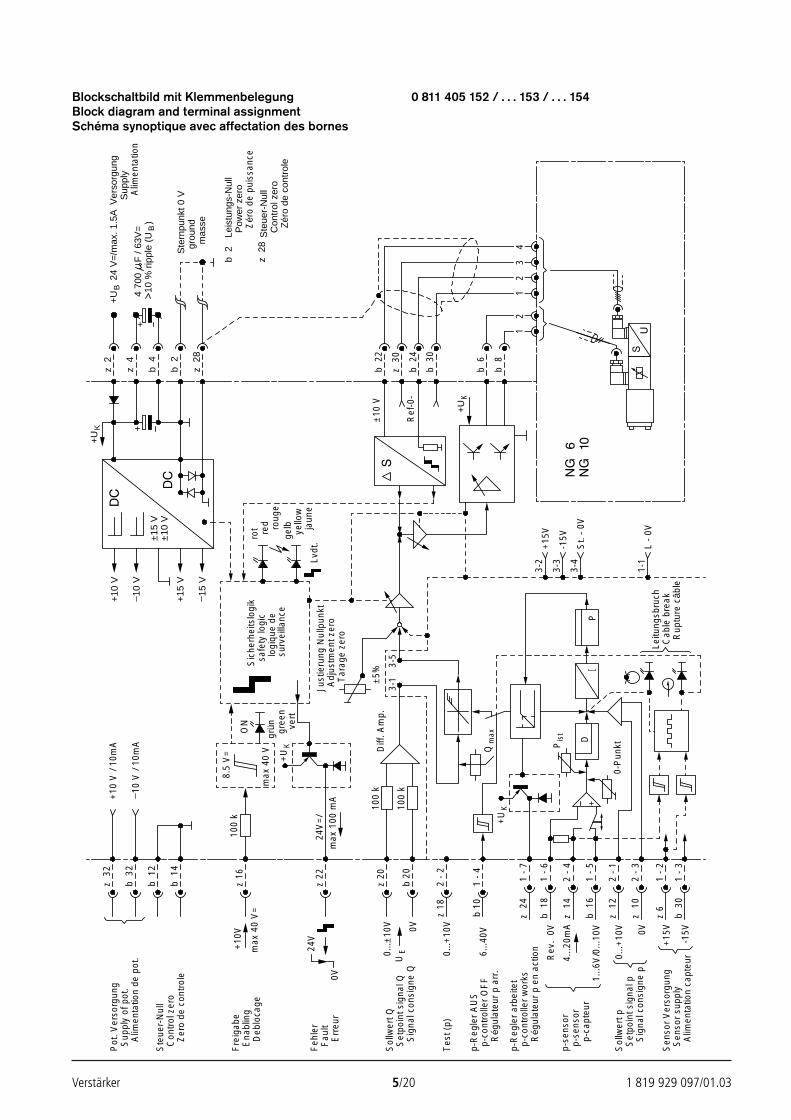
Verstärker 5/20 1 819 929 097/01.03
Blockschaltbild mit Klemmenbelegung 0 811 405 152 / . . . 153 / . . . 154Block diagram and terminal assignmentSchéma synoptique avec affectation des bornes
±15
V±
10 V
++
+U
Kz
2
z 4
b 2
z 2
8
b 4
+10
V
10 V
+15
V
15 V
+U
B
Ver
sorg
ung
Sup
ply
24 V
=/m
ax. 1
.5A
4 70
010
% r
ippl
e (U
B
F /
63V
=)
Ste
rnpu
nkt 0
Vgr
ound
mas
se
b 2
z 2
8
Leis
tung
s-N
ull
Pow
er z
ero
Ste
uer-
Nul
lC
ontr
ol z
ero
Zér
o de
con
trol
e
+U
K
b 6
b 8
z 3
0
b 3
0
b 2
4
±10
V
Ref
-0-
12
12
34
z 3
2
b 3
2
ON
8.5
V=
max
40
Vgr
ün gree
n
z 16
100
k
+10
V
max
40
V=
24V
max
100
mA
24V
=/
z 22
vert
safe
ty lo
gic
logi
que
desu
rvei
llanc
e
Just
ieru
ng N
ullp
unkt
Adj
ustm
ent z
ero
Tar
age
zero
Diff
. Am
p.±
5%
3-1
3-5
z 20
b 20
0V
rot red roug
ege
lbye
llow
jaun
eLv
dt.
DP
0-P
unkt
Leitu
ngsb
ruch
Cab
le b
reak
Rup
ture
câb
le
+15
V3-
2
-15V
3-3
3-4
L -
0V1-
1
St.
- 0V
1 -
6
2 -
4
b 1
8
z 1
4
1 -
7z
24
1 -
5b
16
1 -
2z
6
1 -
3b
30
2 -
1z
12
2 -
3z
10
Pis
t
+
Pot
. Ver
sorg
ung
Sup
ply
of p
ot.
Alim
enta
tion
de p
ot.
Ste
uer-
Nul
lC
ontr
ol z
ero
Zer
o de
con
trol
e
Fre
igab
eE
nabl
ing
Deb
loca
ge
Err
eur
Feh
ler
Fau
lt
Sol
lwer
t QS
etpo
int s
igna
l Q
Tes
t (p)
p-R
egle
r A
US
p-co
ntro
ller
OF
F
p-R
egle
r ar
beite
tp-
cont
rolle
r w
orks
p-se
nsor
p-se
nsor
p-ca
pteu
r
Sen
sor
Ver
sorg
ung
Sen
sor
supp
lyA
limen
tatio
n ca
pteu
r
Sol
lwer
t pS
etpo
int s
igna
l pS
igna
l con
sign
e p
+U
K
UE0.
..±10
V
2 -
2z
18
1 -
4b
10
Rég
ulat
eur
p ar
r.
Rég
ulat
eur
p en
act
ion6...4
0V
0V 0V
-15V
+15
V
Rev
. 0V
4...2
0mA
1...6
V/0
...10
V
b 1
2
b 1
4
+10
V /
10m
A
10 V
/ 10
mA
Sig
nal c
onsi
gne
Q
Zér
o de
pui
ssan
ce
+U
K
Qm
ax
100
k
100
k
Sic
herh
eits
logi
k
0...+
10V
0...+
10V
b 2
2
Alim
enta
tion
24388_4030_001-020 25.02.2003 8:54 Uhr Seite 5
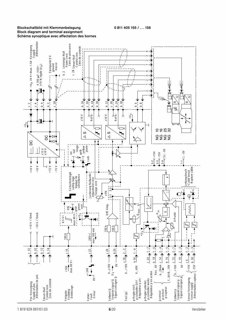
1 819 929 097/01.03 6/20 Verstärker
Blockschaltbild mit Klemmenbelegung 0 811 405 155 / . . . 156Block diagram and terminal assignmentSchéma synoptique avec affectation des bornes
±15
V±
10 V
++
+U
Kz
2
z 4
b 2
z 2
8
b 4
+10
V
10 V
+15
V
15 V
+U
B
Ver
sorg
ung
Sup
ply
24 V
=/m
ax. 1
.5A
4 70
010
% r
ippl
e (U
B
F /
63V
=)
Ste
rnpu
nkt 0
Vgr
ound
mas
se
b 2
z 2
8
Leis
tung
s-N
ull
Pow
er z
ero
Ste
uer-
Nul
lC
ontr
ol z
ero
Zér
o de
con
trol
e
+U
K
b 6
b 8
z 3
0
b 3
0
±10
V
Ref
-0-
12
12
34
z 3
2
b 3
2
ON
8.5
V=
max
40
Vgr
ün gree
n
z 16
100
k
+10
V
max
40
V=
24V
max
100
mA
24V
=/
z 22
vert
safe
ty lo
gic
logi
que
desu
rvei
llanc
e
Just
ieru
ng N
ullp
unkt
Adj
ustm
ent z
ero
Tar
age
zero
Diff
. Am
p.±
5%
3-1
3-5
z 20
b 20
0V
rot red roug
ege
lbye
llow
jaun
eLv
dt.
DP
0-P
unkt
Leitu
ngsb
ruch
Cab
le b
reak
Rup
ture
câb
le
+15
V3-
2
-15V
3-3
3-4
L -
0V1-
1
St.
- 0V
1 -
6
2 -
4
b 1
8
z 1
4
1 -
7z
24
1 -
5b
16
1 -
2z
6
1 -
3b
30
2 -
1z
12
2 -
3z
10
Pis
t
+
Pot
. Ver
sorg
ung
Sup
ply
of p
ot.
Alim
enta
tion
de p
ot.
Ste
uer-
Nul
lC
ontr
ol z
ero
Zer
o de
con
trol
e
Fre
igab
eE
nabl
ing
Deb
loca
ge
Err
eur
Feh
ler
Fau
lt
Sol
lwer
t QS
etpo
int s
igna
l Q
Tes
t (p)
p-R
egle
r A
US
p-co
ntro
ller
OF
F
p-R
egle
r ar
beite
tp-
cont
rolle
r w
orks
p-se
nsor
p-se
nsor
p-ca
pteu
r
Sen
sor
Ver
sorg
ung
Sen
sor
supp
lyA
limen
tatio
n ca
pteu
r
Sol
lwer
t pS
etpo
int s
igna
l pS
igna
l con
sign
e p
+U
K
UE0.
..±10
V
2 -
2z
18
1 -
4b
10
Rég
ulat
eur
p ar
r.
Rég
ulat
eur
p en
act
ion6...4
0V
0V
-15V
+15
V
Rev
. 0V
4...2
0mA
1...6
V/0
...10
V
b 1
2
b 1
4
+10
V /
10m
A
10 V
/ 10
mA
Sig
nal c
onsi
gne
Q
Zér
o de
pui
ssan
ce
+U
K
Qm
ax
100
k
100
k
z 3
0
b 3
0
b 2
4
±10
V
Ref
-0-
12
34
0...+
10V
0...+
10V 0V
Sic
herh
eits
logi
k
b 2
6
b 2
8
b 2
2
Alim
enta
tion
24388_4030_001-020 25.02.2003 8:54 Uhr Seite 6
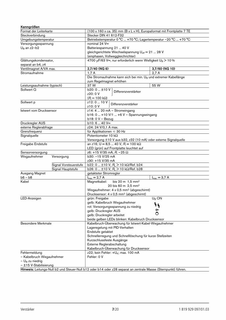
Verstärker 7/20 1 819 929 097/01.03
KenngrößenFormat der Leiterkarte (100 x 160 x ca. 35) mm (B x L x H), Europaformat mit Frontplatte 7 TESteckverbindung Stecker DIN 41 612-F32Umgebungstemperatur Betriebstemperatur 0 °C ... +70 °C; Lagertemperatur –20 °C ... +70 °CVersorgungsspannung nominal 24 V=UB an z2–b2 Batteriespannung 21 ... 40 V
gleichgerichtete Wechselspannung Ueff = 21 ... 28 V(einphasen, Vollweggleichrichter)
Glättungskondensator, 4700 µF/63 V=, nur erforderlich wenn Welligkeit UB > 10 %separat an b4, z4Ventilmagnet A/VA max. 2,7/40 (NG 6) 3,7/60 (NG 10)Stromaufnahme 1,7 A 2,7 A
Die Stromaufnahme kann sich bei min. UB und extremer Kabellängezum Regelmagnet erhöhen
Leistungsaufnahme (typisch) 37 W 55 WSollwert Q b20: 0 ... ±10 V Differenzverstärker
z20: 0 V(Ri = 100 kΩ)
Sollwert p z12: 0 ... 10 V Differenzverstärkerz10: 0 V
Istwert vom Drucksensor z14: 4 ... 20 mA – Stromeingang b16: 0 ... +10 V/1 ... +6 V – Spannungseingangb18: 0 V – Bezug
Druckregler AUS b10: 6 ... 40 V=externe Reglerabfrage z24: 24 V/0,1 A max.Grenzfrequenz für Applikationen 30 HzSignalquelle Potentiometer 10 kΩ
Versorgung ±10 V aus b32, z32 (10 mA) oder externe SignalquelleFreigabe Endstufe an z16; U = 8,5 ... 40 V, Ri = 100 kΩ
LED (grün) auf Frontplatte leuchtet aufSensorversorgung z6: +15 V/35 mA, Ri ~25 ΩWegaufnehmer Versorgung b30: –15 V/25 mA
z30: +15 V/35 mASignal Vorsteuerstufe b22: 0 ... ±10 V, RL > 10 kΩ/Ref. b24Signal Hauptstufe b26: 0 ... ±10 V, RL > 10 kΩ/Ref. b28
Ausgang Magnet getakteter Stromreglerb6 – b8 Imax. = 2,7 A Imax. = 3,7 AKabel Magnetkabel: 20 bis 20 m 1,5 mm2
Magnetkabel: 20 bis 60 m 2,5 mm2
Wegaufnehmer: 4 x 0,5 mm2 (abgeschirmt)Drucksensor: 4 x 0,5 mm2 (abgeschirmt)
LED-Anzeigen grün: Freigabe UB ONgelb: Kabelbruch Wegaufnehmerrot: Versorgungsspannung zu niedriggelb: Druckregler AUSgelb: Druckregler arbeitetbeide gelben LEDs blinken: Kabelbruch Drucksensor
Besondere Merkmale Kabelbruch-Überwachung für Istwert-Kabel-WegaufnehmerLageregelung mit PID-VerhaltenEndstufe getaktetSchnellerregung und Schnelllöschung für kurze StellzeitenKurzschlussfeste AusgängeExterne ReglerabschaltungKabelbruch-Überwachung für Drucksensor
Fehlermeldung z22; kein Fehler: +UK; max. 100 mA– Kabelbruch Wegaufnehmer Fehler: 0 V– UB zu niedrig– ±15 V-StabilisierungHinweis: Leitungs-Null b2 und Steuer-Null b12 oder b14 oder z28 separat an zentrale Masse (Sternpunkt) führen.
24388_4030_001-020 25.02.2003 8:54 Uhr Seite 7
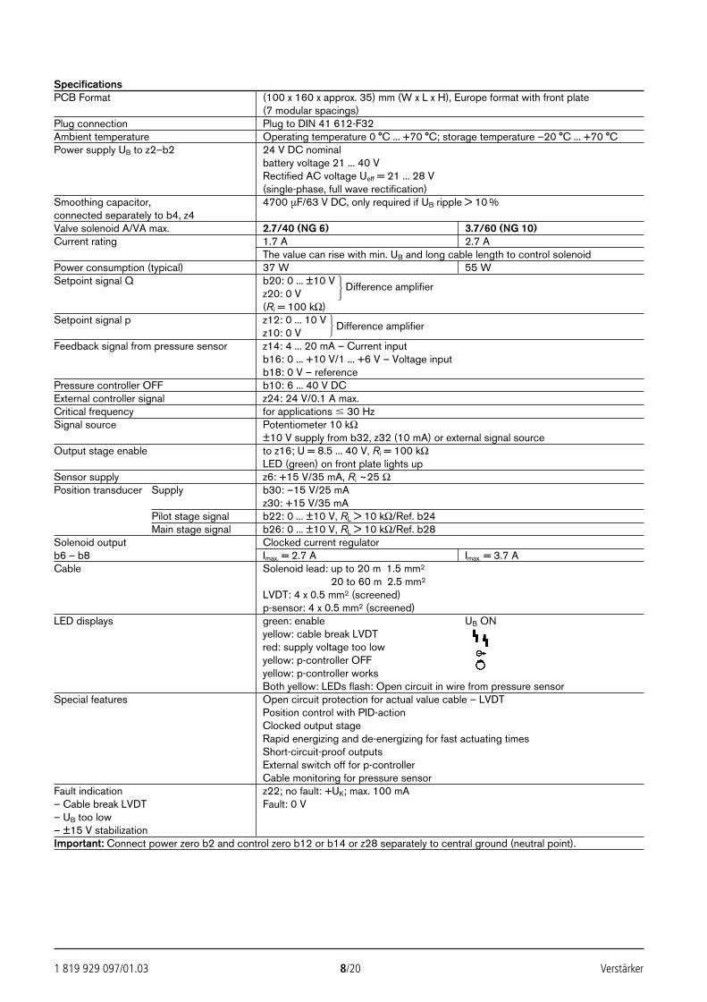
1 819 929 097/01.03 8/20 Verstärker
SpecificationsPCB Format (100 x 160 x approx. 35) mm (W x L x H), Europe format with front plate
(7 modular spacings)Plug connection Plug to DIN 41 612-F32Ambient temperature Operating temperature 0 °C ... +70 °C; storage temperature –20 °C ... +70 °CPower supply UB to z2–b2 24 V DC nominal
battery voltage 21 ... 40 VRectified AC voltage Ueff = 21 ... 28 V(single-phase, full wave rectification)
Smoothing capacitor, 4700 µF/63 V DC, only required if UB ripple > 10 %connected separately to b4, z4Valve solenoid A/VA max. 2.7/40 (NG 6) 3.7/60 (NG 10)Current rating 1.7 A 2.7 A
The value can rise with min. UB and long cable length to control solenoidPower consumption (typical) 37 W 55 WSetpoint signal Q b20: 0 ... ±10 V Difference amplifier
z20: 0 V(Ri = 100 kΩ)
Setpoint signal p z12: 0 ... 10 V Difference amplifierz10: 0 V
Feedback signal from pressure sensor z14: 4 ... 20 mA – Current inputb16: 0 ... +10 V/1 ... +6 V – Voltage inputb18: 0 V – reference
Pressure controller OFF b10: 6 ... 40 V DCExternal controller signal z24: 24 V/0.1 A max.Critical frequency for applications 30 HzSignal source Potentiometer 10 kΩ
±10 V supply from b32, z32 (10 mA) or external signal sourceOutput stage enable to z16; U = 8.5 ... 40 V, Ri = 100 kΩ
LED (green) on front plate lights upSensor supply z6: +15 V/35 mA, Ri ~25 ΩPosition transducer Supply b30: –15 V/25 mA
z30: +15 V/35 mAPilot stage signal b22: 0 ... ±10 V, RL > 10 kΩ/Ref. b24Main stage signal b26: 0 ... ±10 V, RL > 10 kΩ/Ref. b28
Solenoid output Clocked current regulatorb6 – b8 Imax. = 2.7 A Imax. = 3.7 ACable Solenoid lead: up to 20 m 1.5 mm2
Solenoid lead: 20 to 60 m 2.5 mm2
LVDT: 4 x 0.5 mm2 (screened)p-sensor: 4 x 0.5 mm2 (screened)
LED displays green: enable UB ONyellow: cable break LVDTred: supply voltage too lowyellow: p-controller OFFyellow: p-controller worksBoth yellow: LEDs flash: Open circuit in wire from pressure sensor
Special features Open circuit protection for actual value cable – LVDTPosition control with PID-actionClocked output stageRapid energizing and de-energizing for fast actuating timesShort-circuit-proof outputsExternal switch off for p-controllerCable monitoring for pressure sensor
Fault indication z22; no fault: +UK; max. 100 mA– Cable break LVDT Fault: 0 V– UB too low– ±15 V stabilizationImportant: Connect power zero b2 and control zero b12 or b14 or z28 separately to central ground (neutral point).
24388_4030_001-020 25.02.2003 8:54 Uhr Seite 8
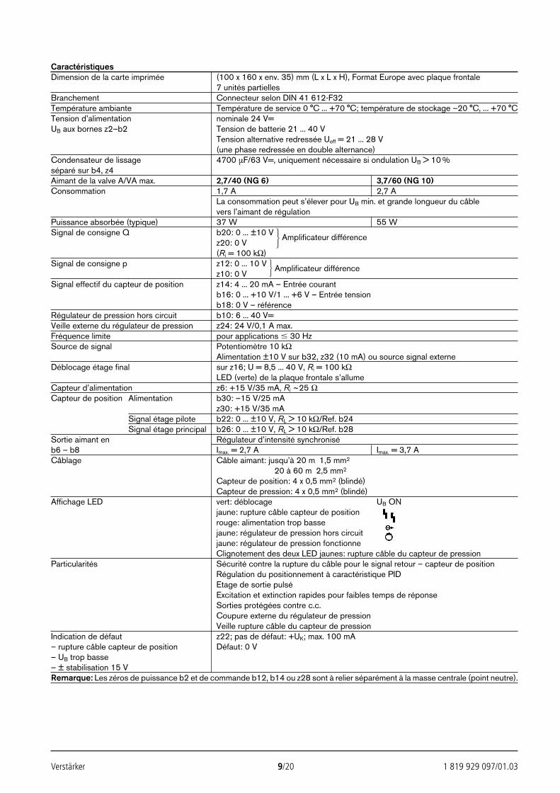
Verstärker 9/20 1 819 929 097/01.03
CaractéristiquesDimension de la carte imprimée (100 x 160 x env. 35) mm (L x L x H), Format Europe avec plaque frontale
7 unités partiellesBranchement Connecteur selon DIN 41 612-F32Température ambiante Température de service 0 °C ... +70 °C; température de stockage –20 °C, ... +70 °CTension d’alimentation nominale 24 V=UB aux bornes z2–b2 Tension de batterie 21 ... 40 V
Tension alternative redressée Ueff = 21 ... 28 V(une phase redressée en double alternance)
Condensateur de lissage 4700 µF/63 V=, uniquement nécessaire si ondulation UB > 10 %séparé sur b4, z4Aimant de la valve A/VA max. 2,7/40 (NG 6) 3,7/60 (NG 10)Consommation 1,7 A 2,7 A
La consommation peut s’élever pour UB min. et grande longueur du câblevers l’aimant de régulation
Puissance absorbée (typique) 37 W 55 WSignal de consigne Q b20: 0 ... ±10 V Amplificateur différence
z20: 0 V(Ri = 100 kΩ)
Signal de consigne p z12: 0 ... 10 V Amplificateur différencez10: 0 V
Signal effectif du capteur de position z14: 4 ... 20 mA – Entrée courantb16: 0 ... +10 V/1 ... +6 V – Entrée tensionb18: 0 V – référence
Régulateur de pression hors circuit b10: 6 ... 40 V=Veille externe du régulateur de pression z24: 24 V/0,1 A max.Fréquence limite pour applications 30 HzSource de signal Potentiomètre 10 kΩ
Alimentation ±10 V sur b32, z32 (10 mA) ou source signal externeDéblocage étage final sur z16; U = 8,5 ... 40 V, Ri = 100 kΩ
LED (verte) de la plaque frontale s’allumeCapteur d’alimentation z6: +15 V/35 mA, Ri ~25 ΩCapteur de position Alimentation b30: –15 V/25 mA
z30: +15 V/35 mASignal étage pilote b22: 0 ... ±10 V, RL > 10 kΩ/Ref. b24Signal étage principal b26: 0 ... ±10 V, RL > 10 kΩ/Ref. b28
Sortie aimant en Régulateur d’intensité synchroniséb6 – b8 Imax. = 2,7 A Imax. = 3,7 ACâblage Câble aimant: jusqu’à 20 m 1,5 mm2
Câble aimant: 20 à 60 m 2,5 mm2
Capteur de position: 4 x 0,5 mm2 (blindé)Capteur de pression: 4 x 0,5 mm2 (blindé)
Affichage LED vert: déblocage UB ONjaune: rupture câble capteur de positionrouge: alimentation trop bassejaune: régulateur de pression hors circuitjaune: régulateur de pression fonctionneClignotement des deux LED jaunes: rupture câble du capteur de pression
Particularités Sécurité contre la rupture du câble pour le signal retour – capteur de positionRégulation du positionnement à caractéristique PIDEtage de sortie pulséExcitation et extinction rapides pour faibles temps de réponseSorties protégées contre c.c.Coupure externe du régulateur de pressionVeille rupture câble du capteur de pression
Indication de défaut z22; pas de défaut: +UK; max. 100 mA– rupture câble capteur de position Défaut: 0 V– UB trop basse– ± stabilisation 15 VRemarque: Les zéros de puissance b2 et de commande b12, b14 ou z28 sont à relier séparément à la masse centrale (point neutre).
24388_4030_001-020 25.02.2003 8:54 Uhr Seite 9
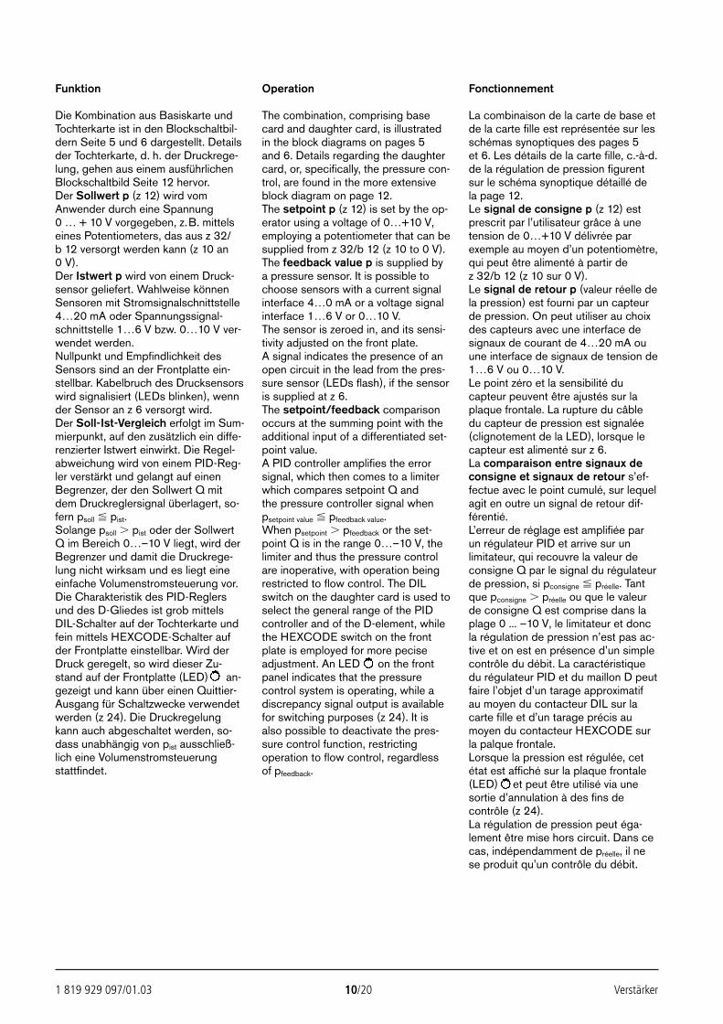
1 819 929 097/01.03 10/20 Verstärker
Funktion
Die Kombination aus Basiskarte undTochterkarte ist in den Blockschaltbil-dern Seite 5 und 6 dargestellt. Detailsder Tochterkarte, d. h. der Druckrege-lung, gehen aus einem ausführlichenBlockschaltbild Seite 12 hervor.Der Sollwert p (z 12) wird vomAnwender durch eine Spannung0 … + 10 V vorgegeben, z.B. mittelseines Potentiometers, das aus z 32/b 12 versorgt werden kann (z 10 an 0 V).Der Istwert p wird von einem Druck-sensor geliefert. Wahlweise könnenSensoren mit Stromsignalschnittstelle4…20 mA oder Spannungssignal-schnittstelle 1…6 V bzw. 0…10 V ver-wendet werden.Nullpunkt und Empfindlichkeit desSensors sind an der Frontplatte ein-stellbar. Kabelbruch des Drucksensorswird signalisiert (LEDs blinken), wennder Sensor an z 6 versorgt wird.Der Soll-Ist-Vergleich erfolgt im Sum-mierpunkt, auf den zusätzlich ein diffe-renzierter Istwert einwirkt. Die Regel-abweichung wird von einem PID-Reg-ler verstärkt und gelangt auf einenBegrenzer, der den Sollwert Q mitdem Druckreglersignal überlagert, so-fern psoll pist.Solange psoll pist oder der SollwertQ im Bereich 0…–10 V liegt, wird derBegrenzer und damit die Druckrege-lung nicht wirksam und es liegt eineeinfache Volumenstromsteuerung vor.Die Charakteristik des PID-Reglersund des D-Gliedes ist grob mittelsDIL-Schalter auf der Tochterkarte undfein mittels HEXCODE-Schalter aufder Frontplatte einstellbar. Wird derDruck geregelt, so wird dieser Zu-stand auf der Frontplatte (LED) an-gezeigt und kann über einen Quittier-Ausgang für Schaltzwecke verwendetwerden (z 24). Die Druckregelungkann auch abgeschaltet werden, so-dass unabhängig von pist ausschließ-lich eine Volumenstromsteuerungstattfindet.
Operation
The combination, comprising basecard and daughter card, is illustratedin the block diagrams on pages 5 and 6. Details regarding the daughtercard, or, specifically, the pressure con-trol, are found in the more extensiveblock diagram on page 12.The setpoint p (z 12) is set by the op-erator using a voltage of 0…+10 V,employing a potentiometer that can besupplied from z 32/b 12 (z 10 to 0 V).The feedback value p is supplied bya pressure sensor. It is possible tochoose sensors with a current signalinterface 4…0 mA or a voltage signalinterface 1…6 V or 0…10 V.The sensor is zeroed in, and its sensi-tivity adjusted on the front plate.A signal indicates the presence of anopen circuit in the lead from the pres-sure sensor (LEDs flash), if the sensoris supplied at z 6.The setpoint/feedback comparisonoccurs at the summing point with theadditional input of a differentiated set-point value.A PID controller amplifies the errorsignal, which then comes to a limiterwhich compares setpoint Q andthe pressure controller signal whenpsetpoint value pfeedback value.When psetpoint pfeedback or the set-point Q is in the range 0…–10 V, thelimiter and thus the pressure controlare inoperative, with operation beingrestricted to flow control. The DILswitch on the daughter card is used toselect the general range of the PIDcontroller and of the D-element, whilethe HEXCODE switch on the frontplate is employed for more peciseadjustment. An LED on the frontpanel indicates that the pressurecontrol system is operating, while adiscrepancy signal output is availablefor switching purposes (z 24). It isalso possible to deactivate the pres-sure control function, restrictingoperation to flow control, regardless of pfeedback.
Fonctionnement
La combinaison de la carte de base etde la carte fille est représentée sur lesschémas synoptiques des pages 5 et 6. Les détails de la carte fille, c.-à-d.de la régulation de pression figurentsur le schéma synoptique détaillé dela page 12.Le signal de consigne p (z 12) estprescrit par l’utilisateur grâce à unetension de 0…+10 V délivrée parexemple au moyen d’un potentiomètre,qui peut être alimenté à partir de z 32/b 12 (z 10 sur 0 V).Le signal de retour p (valeur réelle dela pression) est fourni par un capteurde pression. On peut utiliser au choixdes capteurs avec une interface designaux de courant de 4…20 mA ouune interface de signaux de tension de1…6 V ou 0…10 V.Le point zéro et la sensibilité ducapteur peuvent être ajustés sur laplaque frontale. La rupture du câbledu capteur de pression est signalée(clignotement de la LED), lorsque lecapteur est alimenté sur z 6.La comparaison entre signaux deconsigne et signaux de retour s’ef-fectue avec le point cumulé, sur lequelagit en outre un signal de retour dif-férentié.L’erreur de réglage est amplifiée parun régulateur PID et arrive sur unlimitateur, qui recouvre la valeur deconsigne Q par le signal du régulateurde pression, si pconsigne préelle. Tantque pconsigne préelle ou que le valeurde consigne Q est comprise dans laplage 0 ... –10 V, le limitateur et doncla régulation de pression n’est pas ac-tive et on est en présence d’un simplecontrôle du débit. La caractéristiquedu régulateur PID et du maillon D peutfaire l’objet d’un tarage approximatifau moyen du contacteur DIL sur lacarte fille et d’un tarage précis aumoyen du contacteur HEXCODE surla palque frontale.Lorsque la pression est régulée, cetétat est affiché sur la plaque frontale(LED) et peut être utilisé via unesortie d’annulation à des fins decontrôle (z 24).La régulation de pression peut éga-lement être mise hors circuit. Dans cecas, indépendamment de préelle, il nese produit qu’un contrôle du débit.
24388_4030_001-020 25.02.2003 8:54 Uhr Seite 10
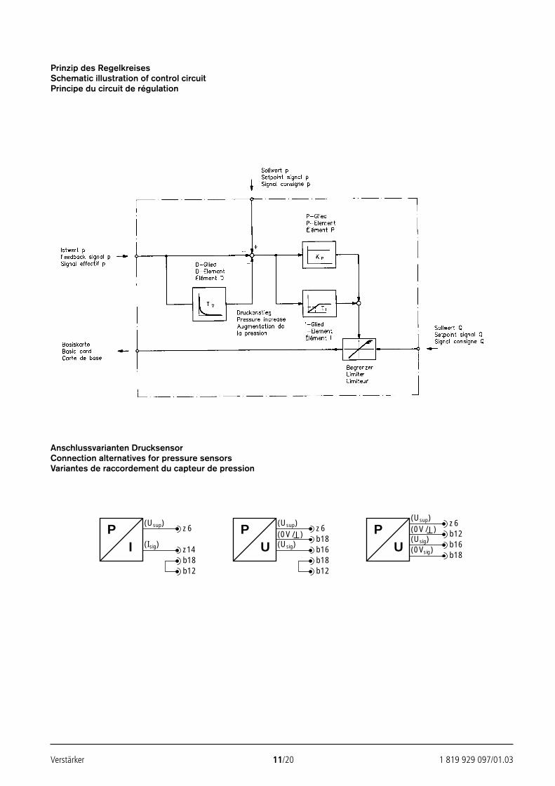
Verstärker 11/20 1 819 929 097/01.03
Prinzip des RegelkreisesSchematic illustration of control circuitPrincipe du circuit de régulation
Anschlussvarianten DrucksensorConnection alternatives for pressure sensorsVariantes de raccordement du capteur de pression
(Usup)PI
z6
(Isig) z14
(Usup)PU
z6(0V/ ) b18(Usig) b16
b18b12
b18b12
(Usup)
PU
z6(0V/ ) b12(Usig) b16(0Vsig)
b18
24388_4030_001-020 25.02.2003 8:54 Uhr Seite 11
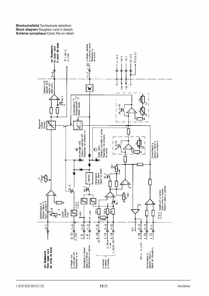
1 819 929 097/01.03 12/20 Verstärker
Blockschaltbild Tochterkarte detailliertBlock diagram Daughter card in detailsSchéma synoptique Carte fille en détail
24388_4030_001-020 25.02.2003 8:54 Uhr Seite 12
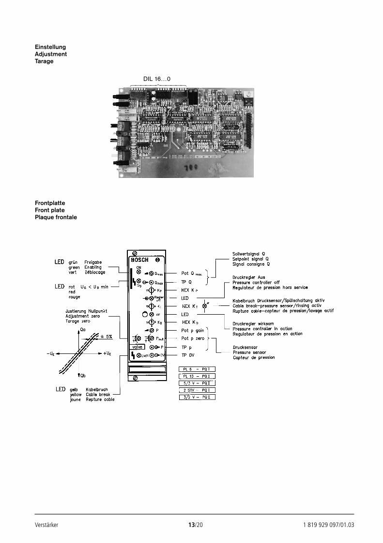
Verstärker 13/20 1 819 929 097/01.03
EinstellungAdjustmentTarage
FrontplatteFront platePlaque frontale
DIL 16…0
24388_4030_001-020 25.02.2003 8:54 Uhr Seite 13
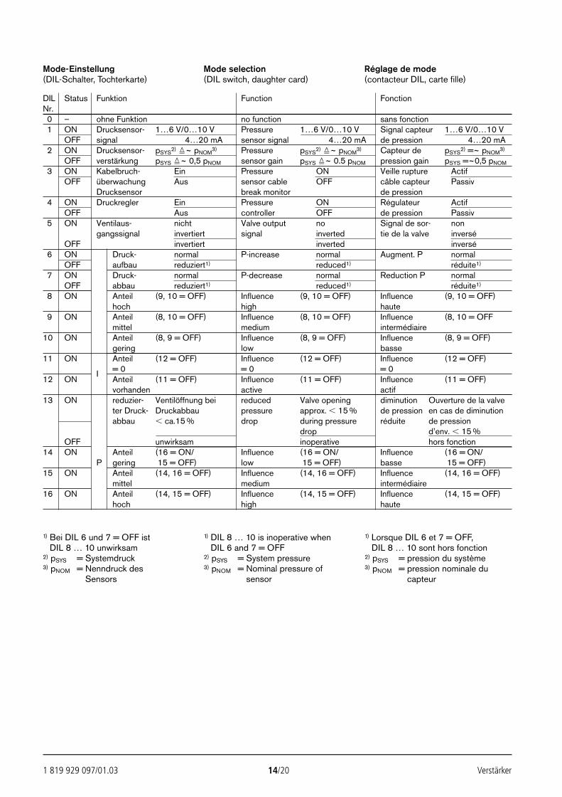
1 819 929 097/01.03 14/20 Verstärker
Mode-Einstellung(DIL-Schalter, Tochterkarte)
Mode selection(DIL switch, daughter card)
Réglage de mode(contacteur DIL, carte fille)
DIL Status Funktion Function FonctionNr.0 – ohne Funktion no function sans fonction1 ON Drucksensor- 1…6 V/0…10 V Pressure 1…6 V/0…10 V Signal capteur 1…6 V/0…10 V
OFF signal 4…20 mA sensor signal 4…20 mA de pression 4…20 mA2 ON Drucksensor- pSYS
2) ~ pNOM3) Pressure pSYS
2) ~ pNOM3) Capteur de pSYS
2) =~ pNOM3)
OFF verstärkung pSYS ~ 0,5 pNOM sensor gain pSYS ~ 0.5 pNOM pression gain pSYS =~0,5 pNOM
3 ON Kabelbruch- Ein Pressure ON Veille rupture ActifOFF überwachung Aus sensor cable OFF câble capteur Passiv
Drucksensor break monitor de pression4 ON Druckregler Ein Pressure ON Régulateur Actif
OFF Aus controller OFF de pression Passiv5 ON Ventilaus- nicht Valve output no Signal de sor- non
gangssignal invertiert signal inverted tie de la valve inverséOFF invertiert inverted inversé
6 ON Druck- normal P-increase normal Augment. P normalOFF aufbau reduziert1) reduced1) réduite1)
7 ON Druck- normal P-decrease normal Reduction P normalOFF abbau reduziert1) reduced1) réduite1)
8 ON Anteil (9, 10 = OFF) Influence (9, 10 = OFF) Influence (9, 10 = OFF)hoch high haute
9 ON Anteil (8, 10 = OFF) Influence (8, 10 = OFF) Influence (8, 10 = OFFmittel medium intermédiaire
10 ON Anteil (8, 9 = OFF) Influence (8, 9 = OFF) Influence (8, 9 = OFF)gering low basse
11 ON Anteil (12 = OFF) Influence (12 = OFF) Influence (12 = OFF)
I = 0 = 0 = 012 ON Anteil (11 = OFF) Influence (11 = OFF) Influence (11 = OFF)
vorhanden active actif13 ON reduzier- Ventilöffnung bei reduced Valve opening diminution Ouverture de la valve
ter Druck- Druckabbau pressure approx. 15 % de pression en cas de diminutionabbau ca.15 % drop during pressure réduite de pression
drop d’env. 15 %OFF unwirksam inoperative hors fonction
14 ON Anteil (16 = ON/ Influence (16 = ON/ Influence (16 = ON/P gering 15 = OFF) low 15 = OFF) basse 15 = OFF)
15 ON Anteil (14, 16 = OFF) Influence (14, 16 = OFF) Influence (14, 16 = OFF)mittel medium intermédiaire
16 ON Anteil (14, 15 = OFF) Influence (14, 15 = OFF) Influence (14, 15 = OFF)hoch high haute
1) Bei DIL 6 und 7 = OFF istDIL 8 … 10 unwirksam
2) pSYS = Systemdruck3) pNOM = Nenndruck des
Sensors
1) DIL 8 … 10 is inoperative when1) DIL 6 and 7 = OFF2) pSYS = System pressure3) pNOM = Nominal pressure of
sensor
1) Lorsque DIL 6 et 7 = OFF,1) DIL 8 … 10 sont hors fonction2) pSYS = pression du système3) pNOM = pression nominale du
capteur
24388_4030_001-020 25.02.2003 8:54 Uhr Seite 14
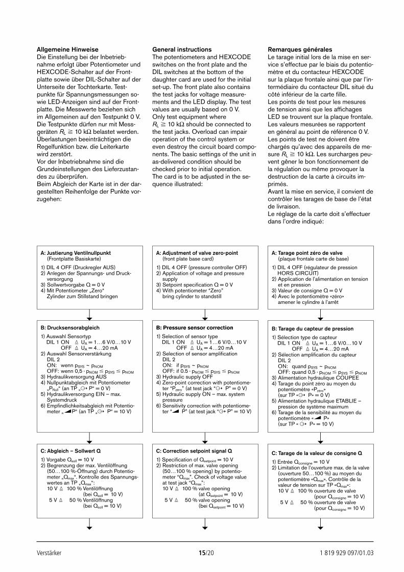
Verstärker 15/20 1 819 929 097/01.03
Allgemeine HinweiseDie Einstellung bei der Inbetrieb-nahme erfolgt über Potentiometer undHEXCODE-Schalter auf der Front-platte sowie über DIL-Schalter auf derUnterseite der Tochterkarte. Test-punkte für Spannungsmessungen so-wie LED-Anzeigen sind auf der Front-platte. Die Messwerte beziehen sichim Allgemeinen auf den Testpunkt 0 V.Die Testpunkte dürfen nur mit Mess-geräten RL 10 kΩ belastet werden.Überlastungen beeinträchtigen dieRegelfunktion bzw. die Leiterkartewird zerstört.Vor der Inbetriebnahme sind dieGrundeinstellungen des Lieferzustan-des zu überprüfen.Beim Abgleich der Karte ist in der dar-gestellten Reihenfolge der Punkte vor-zugehen:
General instructionsThe potentiometers and HEXCODEswitches on the front plate and theDIL switches at the bottom of thedaughter card are used for the initialset-up. The front plate also containsthe test jacks for voltage measure-ments and the LED display. The testvalues are usually based on 0 V.Only test equipment where RL 10 kΩ should be connected tothe test jacks. Overload can impairoperation of the control system oreven destroy the circuit board compo-nents. The basic settings of the unit inas-delivered condition should bechecked prior to initial operation.The card is to be adjusted in the se-quence illustrated:
Remarques généralesLe tarage initial lors de la mise en ser-vice s’effectue par le biais du potentio-mètre et du contacteur HEXCODEsur la plaque frontale ainsi que par l’in-termédiaire du contacteur DIL situé ducôté inférieur de la carte fille.Les points de test pour les mesuresde tension ainsi que les affichagesLED se trouvent sur la plaque frontale.Les valeurs mesurées se rapportenten général au point de référence 0 V.Les points de test ne doivent êtrechargés qu’avec des appareils de me-sure RL 10 kΩ. Les surcharges peu-vent gêner le bon fonctionnement dela régulation ou même provoquer ladestruction de la carte à circuits im-primés.Avant la mise en service, il convient decontrôler les tarages de base de l’étatde livraison.Le réglage de la carte doit s’effectuerdans l’ordre indiqué:
A: Tarage point zéro de valve(plaque frontale carte de base)
1) DIL 4 OFF (régulateur de pressionHORS CIRCUIT)
2) Application de l’alimentation en tensionet en pression
3) Valeur de consigne Q = 0 V4) Avec le potentiomètre «zéro»
amener le cylindre à l’arrêt
A: Adjustment of valve zero-point(front plate base card)
1) DIL 4 OFF (pressure controller OFF)2) Application of voltage and pressure
supply3) Setpoint specification Q = 0 V4) With potentiometer “Zero”
bring cylinder to standstill
A: Justierung Ventilnullpunkt(Frontplatte Basiskarte)
1) DIL 4 OFF (Druckregler AUS)2) Anlegen der Spannungs- und Druck-
versorgung3) Sollwertvorgabe Q = 0 V4) Mit Potentiometer „Zero“
Zylinder zum Stillstand bringen
C: Abgleich – Sollwert Q
1) Vorgabe Qsoll = 10 V2) Begrenzung der max. Ventilöffnung
(50…100 %-Öffnung) durch Potentio-meter „Qmax“. Kontrolle des Spannungs-wertes an TP „Qmax“:10 V 100 % Ventilöffnung
(bei Qsoll = 10 V)5 V 50 % Ventilöffnung
(bei Qsoll = 10 V)
C: Correction setpoint signal Q
1) Specification of Qsetpoint = 10 V2) Restriction of max. valve opening
(50…100 % opening) by potentio-meter “Qmax”. Check of voltage valueat test jack “Qmax”:10 V 100 % valve opening
(at Qsetpoint = 10 V)5 V 50 % valve opening
(bei Qsetpoint = 10 V)
C: Tarage de la valeur de consigne Q
1) Entrée Qconsigne = 10 V2) Limitation de l’ouverture max. de la valve
(ouverture 50…100 %) au moyen dupotentiomètre «Qmax». Contrôle de lavaleur de tension sur TP «Qmax»:10 V 100 % ouverture de valve
(pour Qconsigne = 10 V)5 V 50 % ouverture de valve
(pour Qconsigne = 10 V)
B: Drucksensorabgleich
1) Auswahl SensortypDIL 1 ON UA = 1…6 V/0…10 V
OFF UA = 4…20 mA2) Auswahl Sensorverstärkung
DIL 2ON: wenn pSYS ~ pNOMOFF: wenn 0,5 · pNOM pSYS pNOM
3) Hydraulikversorgung AUS4) Nullpunktabgleich mit Potentiometer
„PNull“ (an TP „ P“ = 0 V)5) Hydraulikversorgung EIN – max.
Systemdruck6) Empfindlichkeitsabgleich mit Potentio-
meter „ P“ (an TP „ P“ = 10 V)
B: Pressure sensor correction
1) Selection of sensor typeDIL 1 ON UA = 1…6 V/0…10 V
OFF UA = 4…20 mA2) Selection of sensor amplification
DIL 2ON: if pSYS ~ pNOMOFF: if 0.5 · pNOM pSYS pNOM
3) Hydraulic supply OFF4) Zero-point correction with potentiome-
ter “Pzero” (at test jack “ P” = 0 V)5) Hydraulic supply ON – max. system
pressure6) Sensitivity correction with potentiome-
ter “ P” (at test jack “ P” = 10 V)
B: Tarage du capteur de pression
1) Sélection type de capteurDIL 1 ON UA = 1…6 V/0…10 V
OFF UA = 4…20 mA2) Sélection amplification du capteur
DIL 2ON: quand pSYS ~ pNOMOFF: quand 0,5 · pNOM pSYS pNOM
3) Alimentation hydraulique COUPEE4) Tarage du point zéro au moyen du
potentiomètre «Pzéro»(sur TP « P» = 0 V)
5) Alimentation hydraulique ETABLIE –pression de système maximum
6) Tarage de la sensibilité au moyen dupotentiomètre « P»(sur TP « P» = 10 V)
24388_4030_001-020 25.02.2003 8:54 Uhr Seite 15
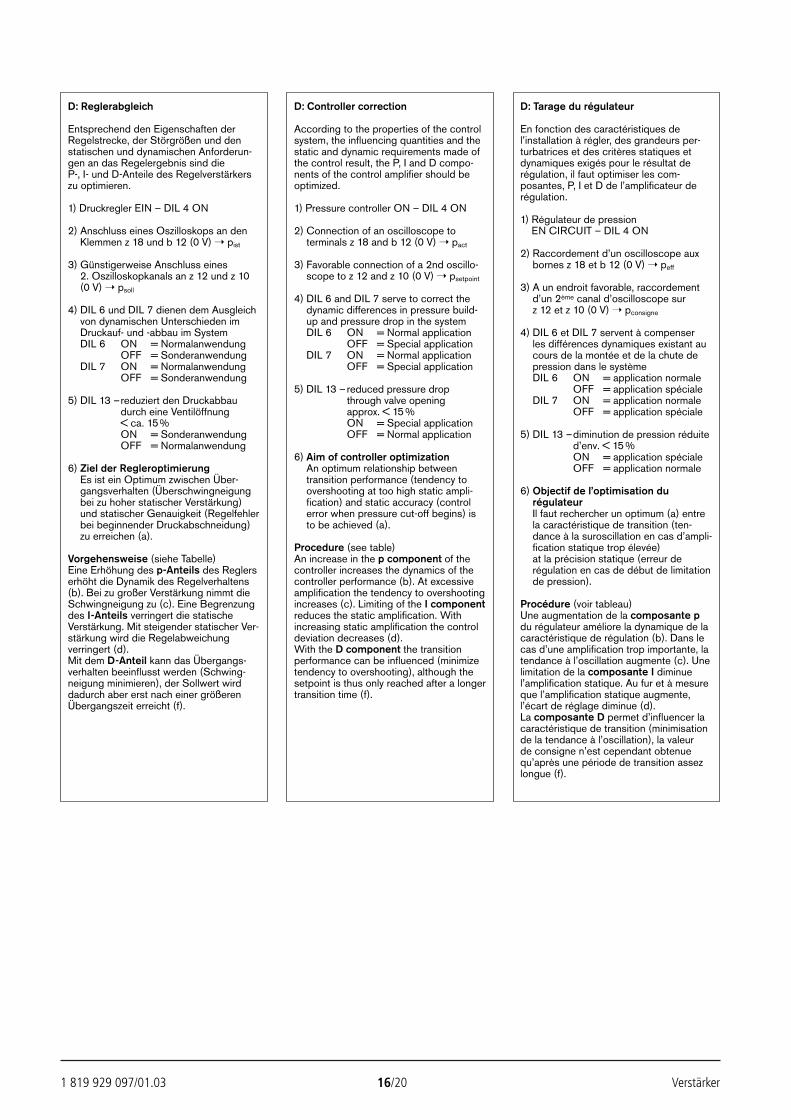
1 819 929 097/01.03 16/20 Verstärker
D: Tarage du régulateur
En fonction des caractéristiques del’installation à régler, des grandeurs per-turbatrices et des critères statiques etdynamiques exigés pour le résultat derégulation, il faut optimiser les com-posantes, P, I et D de l’amplificateur derégulation.
1) Régulateur de pressionEN CIRCUIT – DIL 4 ON
2) Raccordement d’un oscilloscope auxbornes z 18 et b 12 (0 V) peff
3) A un endroit favorable, raccordementd’un 2ème canal d’oscilloscope sur z 12 et z 10 (0 V) pconsigne
4) DIL 6 et DIL 7 servent à compenser les différences dynamiques existant aucours de la montée et de la chute depression dans le systèmeDIL 6 ON = application normale
OFF = application spécialeDIL 7 ON = application normale
OFF = application spéciale
5) DIL 13 –diminution de pression réduited’env. < 15 %ON = application spécialeOFF = application normale
6) Objectif de l’optimisation durégulateurIl faut rechercher un optimum (a) entrela caractéristique de transition (ten-dance à la suroscillation en cas d’ampli-fication statique trop élevée) at la précision statique (erreur derégulation en cas de début de limitationde pression).
Procédure (voir tableau)Une augmentation de la composante pdu régulateur améliore la dynamique de lacaractéristique de régulation (b). Dans lecas d’une amplification trop importante, latendance à l’oscillation augmente (c). Unelimitation de la composante I diminuel’amplification statique. Au fur et à mesureque l’amplification statique augmente,l’écart de réglage diminue (d).La composante D permet d’influencer lacaractéristique de transition (minimisationde la tendance à l’oscillation), la valeur de consigne n’est cependant obtenuequ’après une période de transition assezlongue (f).
D: Controller correction
According to the properties of the controlsystem, the influencing quantities and thestatic and dynamic requirements made ofthe control result, the P, I and D compo-nents of the control amplifier should beoptimized.
1) Pressure controller ON – DIL 4 ON
2) Connection of an oscilloscope toterminals z 18 and b 12 (0 V) pact
3) Favorable connection of a 2nd oscillo-scope to z 12 and z 10 (0 V) psetpoint
4) DIL 6 and DIL 7 serve to correct thedynamic differences in pressure build-up and pressure drop in the systemDIL 6 ON = Normal application
OFF = Special applicationDIL 7 ON = Normal application
OFF = Special application
5) DIL 13 –reduced pressure dropthrough valve openingapprox. < 15 %ON = Special applicationOFF = Normal application
6) Aim of controller optimizationAn optimum relationship betweentransition performance (tendency toovershooting at too high static ampli-fication) and static accuracy (controlerror when pressure cut-off begins) isto be achieved (a).
Procedure (see table)An increase in the p component of thecontroller increases the dynamics of thecontroller performance (b). At excessiveamplification the tendency to overshootingincreases (c). Limiting of the I componentreduces the static amplification. Withincreasing static amplification the controldeviation decreases (d).With the D component the transitionperformance can be influenced (minimizetendency to overshooting), although thesetpoint is thus only reached after a longertransition time (f).
D: Reglerabgleich
Entsprechend den Eigenschaften derRegelstrecke, der Störgrößen und denstatischen und dynamischen Anforderun-gen an das Regelergebnis sind dieP-, I- und D-Anteile des Regelverstärkerszu optimieren.
1) Druckregler EIN – DIL 4 ON
2) Anschluss eines Oszilloskops an denKlemmen z 18 und b 12 (0 V) pist
3) Günstigerweise Anschluss eines2. Oszilloskopkanals an z 12 und z 10(0 V) psoll
4) DIL 6 und DIL 7 dienen dem Ausgleichvon dynamischen Unterschieden imDruckauf- und -abbau im SystemDIL 6 ON = Normalanwendung
OFF = SonderanwendungDIL 7 ON = Normalanwendung
OFF = Sonderanwendung
5) DIL 13 –reduziert den Druckabbaudurch eine Ventilöffnung< ca. 15%ON = SonderanwendungOFF = Normalanwendung
6) Ziel der RegleroptimierungEs ist ein Optimum zwischen Über-gangsverhalten (Überschwingneigungbei zu hoher statischer Verstärkung)und statischer Genauigkeit (Regelfehlerbei beginnender Druckabschneidung)zu erreichen (a).
Vorgehensweise (siehe Tabelle)Eine Erhöhung des p-Anteils des Reglerserhöht die Dynamik des Regelverhaltens(b). Bei zu großer Verstärkung nimmt dieSchwingneigung zu (c). Eine Begrenzungdes I-Anteils verringert die statischeVerstärkung. Mit steigender statischer Ver-stärkung wird die Regelabweichungverringert (d).Mit dem D-Anteil kann das Übergangs-verhalten beeinflusst werden (Schwing-neigung minimieren), der Sollwert wirddadurch aber erst nach einer größerenÜbergangszeit erreicht (f).
24388_4030_001-020 25.02.2003 8:54 Uhr Seite 16
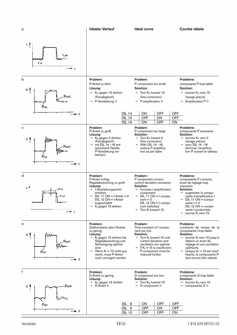
Verstärker 17/20 1 819 929 097/01.03
Idealer Verlauf Ideal curve Courbe idéale
Problem:P-Anteil zu kleinLösung: KP gegen 13 drehen
(Feinabgleich) P-Verstärkung >
Problem:P component too smallSolution: Turn KP toward 13
(fine-correction) P amplification >
Problème:composante P trop faibleSolution: tourner KP vers 13
(tarage précis) Amplification P >
Problem:P-Anteil zu großLösung: KP gegen 0 drehen
(Feinabgleich) mit DIL 14 –16 ent-
sprechend TabelleP-Verstärkung ver-kleinern
Problem:P component too largeSolution: Turn KP toward 0
(fine-correction) With DIL 14 –16,
reduce P amplifica-tion as per table
Problème:composante P excessiveSolution: tourner KP vers 0
(tarage précis) avec DIL 14 –16
diminuer l’amplifica-tion P suivant le tableau
Problem:P-Anteil richtig,Regelabweichung zu großLösung: I-Verstärkungsanteil
erhöhen DIL 11 ON = I-Anteil = 0
DIL 12 ON = I-Anteilzugeschaltet
KI gegen 13 drehen
Problem:P component correct,control deviation excessiveSolution: Increase I amplification
component DIL 11 ON = I compo-
nent = 0DIL 12 ON = I compo-nent switched
Turn KI toward 13
Problème:composante P correcte,écart de réglage tropimportantSolution: augmenter la compo-
sante d’amplification I DIL 11 ON = compo-
sante I = 0DIL 12 ON = compo-sante I enclenchés
tourner KI vers 13
Problem:Zeitkonstante des I-Anteilszu geringLösung: KI gegen 13 drehen bis
Regelabweichung undSchwingung optimalsind
Wenn KI = 13 nicht aus-reicht, muss P-Anteilnoch verringert werden
Problem:Time constant of I compo-nent too lowSolution: Turn KI toward 13 until
control deviation andoscillation are optimal
If KI = 13 is insufficient,P component must bereduced further
Problème:constante de temps de lacomposante I trop faibleSolution: tourner KI vers 13 jusqu’à
obtenir un écart deréglage et une oscillationoptimums
lorsque KI = 13 est insuf-fisante, la composante Pdoit encore être réduite
Problem:D-Anteil zu geringLösung: KD gegen 13 drehen D-Anteil >
Problem:D component too lowSolution: Turn KD toward 13 D component >
Problème:composante D trop faibleSolution: tourner KD vers 13 composante D >
a
b
c
d
e
f
DIL 14 ON OFF OFFDIL 15 OFF ON OFFDIL 16 ON OFF ON
DIL 8 ON OFF OFFDIL 9 OFF ON OFFDIL 10 OFF OFF ON
24388_4030_001-020 25.02.2003 8:54 Uhr Seite 17
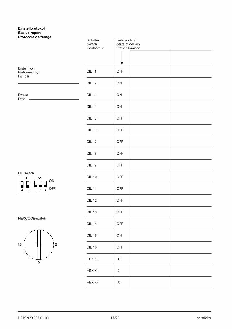
1 819 929 097/01.03 18/20 Verstärker
EinstellprotokollSet-up reportProtocole de tarage
Schalter LieferzustandSwitch State of deliveryContacteur Etat de livraison
Erstellt vonPerformed by DIL 1 OFFFait par
DIL 2 ON
Datum DIL 3 ONDate
DIL 4 ON
DIL 5 OFF
DIL 6 OFF
DIL 7 OFF
DIL 8 OFF
DIL 9 OFF
DIL-switchDIL 10 OFF
ON
OFF DIL 11 OFF
DIL 12 OFF
DIL 13 OFF
HEXCODE-switch
DIL 14 OFF
DIL 15 ON
DIL 16 OFF
HEX KP 3
HEX KI 9
HEX KD 5
1
9
13 5
24388_4030_001-020 25.02.2003 8:54 Uhr Seite 18
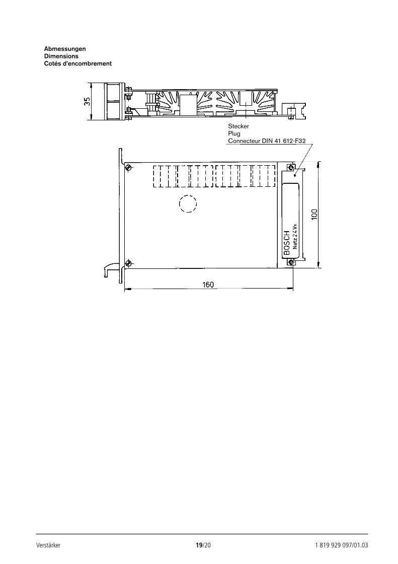
Verstärker 19/20 1 819 929 097/01.03
AbmessungenDimensionsCotés d’encombrement
SteckerPlugConnecteur DIN 41 612-F32
24388_4030_001-020 25.02.2003 8:54 Uhr Seite 19

Bosch Rexroth AG Die angegebenen Daten dienen allein derIndustrial Hydraulics Produktbeschreibung. Eine Aussage über eineD-97813 Lohr am Main bestimmte Beschaffenheit oder eine Eignung fürZum Eisengießer 1 D-97816 Lohr am Main einen bestimmten Einsatzzweck kann ausTelefon 0 93 52/18-0 unseren Angaben nicht abgeleitet werden. Es istTelefax 0 93 52/18-23 58 Telex 6 89 418-0 zu beachten, dass unsere Produkte einemeMail [email protected] natürlichen Verschleiß- und AlterungsprozessInternet www.boschrexroth.de unterliegen.
1 819 929 097/01.03 20/20 Verstärker
24388_4030_001-020 25.02.2003 8:54 Uhr Seite 20
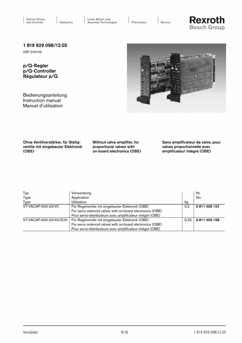
1 819 929 098/12.05UBY 013/125
p/Q-Reglerp/Q-ControllerRégulateur p/Q
BedienungsanleitungInstruction manualManuel d’utilisation
Verstärker 1/16 1 819 929 098/12.05
Ohne Ventilverstärker, für Stetig-ventile mit eingebauter Elektronik(OBE)
Without valve amplifier, forproportional valves withon-board electronics (OBE)
Sans amplificateur de valve, pourvalves proportionnelle avecamplificateur intégré (OBE)
Typ Verwendung Nr.Type Application No.Type Utilisation kgVT-VACAP-500-20/V0 Für Regelventile mit eingebauter Elektronik (OBE) 0,2 0 811 405 157
For servo solenoid valves with on-board electronics (OBE)Pour servo-distributeurs avec amplificateur intégré (OBE)
VT-VACAP-500-20/V0/2CH Für Regelventile mit eingebauter Elektronik (OBE) 0,25 0 811 405 158For servo solenoid valves with on-board electronics (OBE)Pour servo-distributeurs avec amplificateur intégré (OBE)
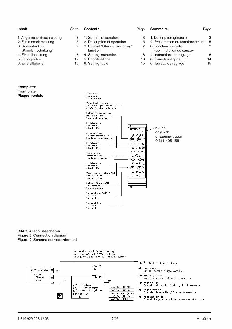
1 819 929 098/12.05 2/16 Verstärker
Inhalt Seite
1. Allgemeine Beschreibung 32. Funktionsdarstellung 53. Sonderfunktion 7
„Kanalumschaltung“4. Einstellanleitung 85. Kenngrößen 126. Einstelltabelle 15
Contents Page
1. General description 32. Description of operation 53. Special “Channel switching” 7
function4. Setting instructions 85. Specifications 136. Setting table 15
Sommaire Page
1. Description générale 32. Présentation du fonctionnement 53. Fonction spéciale 7
«commutation de canaux»4. Instructions de réglage 85. Caractéristiques 146. Tableau de réglage 15
FrontplatteFront platePlaque frontale
Bild 2: AnschlussschemaFigure 2: Connection diagramFigure 2: Schéma de raccordement
nur beionly withuniquement pour0 811 405 158
Verstärker 3/16 1 819 929 098/12.05
Anwendungen
Die „1-Kanal-p/Q-Regelkarte“ bestehtaus der Basiskarte im Europaformatmit DC/DC-Wandler und Frontplatte.Bei der „2-Kanal-p/Q-Regelkarte“ er-hält diese Basiskarte eine schaltungs-gleiche p/Q-Tochterkarte und eine ge-meinsame Frontplatte.Die Versorgungsspannung beträgt 24 V=. Die Spannungsversorgung deszu regelnden Ventils erfolgt nicht überdiese Karte.Eingangsgrößen für die Karten sindder Ventillagesollwert, der Drucksoll-wert, der Druckistwert und möglicheSteuermodesignale. Die Drucksenso-ren mit Spannungsschnittstelle erhal-ten ihre Spannungsversorgung vonder Karte (z6/z8).An den Karten können Drucksensorenmit Spannungs- und Stromsignal an-geschlossen werden.Der Drucksollwert lässt sich mittelsPotentiometer vorgeben. Die Potentio-meter können aus der Karte (z32/b12)versorgt werden.Für Kontrolle und Abgleich sind in derFrontplatte und auf der LeiterkarteTestpunkte für die wichtigsten Kenn-größen vorhanden.Die Schaltung der „2-Kanal-Karte“ istso ausgelegt, dass die Regler aufBasis- und Tochterkarte völlig unab-hängig voneinander arbeiten. Indiesem Modus ist die Karte zumRegeln von 2 Ventilen mit integrierterElektronik geeignet (siehe Beispiel 2).Eine zusätzliche Kanalmodeschaltunggestattet, die Einsatzmöglichkeiten der beschriebenen Karte wesentlichzu erweitern (siehe Beispiel 1).
Applications
The “single-channel p/Q controllercard” consists of the base card instandard Europe format together withDC/DC converter and front plate. The “2-channel p/Q controller card”version consists of this same basecard equipped with an additional p/Qdaughter card incorporating the samecircuity. The two cards share a com-mon front plateThe supply voltage is 24 V DC. Thiscard does not provide the powersupply for the valve being regulated.The input parameters for the cardscomprise the setpoint value for valveposition, the setpoint value for pres-sure, the actual (feedback) pressureand any control mode signals. Thepressure sensors with voltage inter-face receive their voltage supply fromthe card (z6/z8).Cards are for the connection of pres-sure sensors with both voltage andcurrent signals.The setpoint value for pressure isselected via potentiometer. The poten-tiometers can be supplied from thecard (z32/b12).Test connections in the front plate andon the card are available for monitor-ing and compensation tuning of themost important parameters.The circuitry of the “2-channel card” isdesigned to allow fully independentoperation of the controller on the basecard and that on the daughter card. Inthis mode the card can be employedto control 2 valves with on-boardelectronics, see example 2.An additional channel mode circuitprovides a substantial increase in therange of optional applications forthese cards, see example 1.
Applications
La «carte p/Q à canal unique» se com-pose d’une carte de base au formatEurope avec convertisseur DC/DC etplaque frontale. Dans le cas de la «carte de régulation p/Q à deuxcanaux», cette carte de base est dotéed’une carte fille p/Q à circuit impriméidentique et d’une plaque frontalecommune.L’alimentation en tension est de 24 V=. L’alimentation en tension de la valve devant faire l’objet de la régu-lation n’est pas assurée par l’inter-médiaire de cette carte.Les caractéristiques d’entrée descartes sont le signal de consigne deposition de valve, le signal de con-signe de pression, le signal de retourde pression et autres signaux pos-sibles du mode de commande. Lescapteurs de pression à interface detension sont alimentés en tension par la carte (z6/z8).Des capteurs de pression avec signalde tension et de courant peuvent êtreraccordés aux cartes.Le signal de consigne de pressionpeut être programme à l’avance aumoyen des potentiomètres. Ces der-niers peuvent être alimentés par lacarte (z32/b12).Afin de permettre le contrôle et letarage, des points test pour les carac-téristiques les plus importantes setrouvent sur la plaque frontale et lacarte imprimée.Le circuit de la «carte à 2 canaux» estconçu de manière à ce que les régula-teurs de la carte de base et de la cartefille fonctionnement de façon entière-ment indépendante. La carte permet-tant la régulation de 2 valves à amplifi-cateur intégré est adaptée à ce mode(voir exemple 2).Un circuit supplémentaire de mode de commutation de canaux permetd’élargir le champ d’application de lacarte décrite ci-dessus (voir exemple 1).
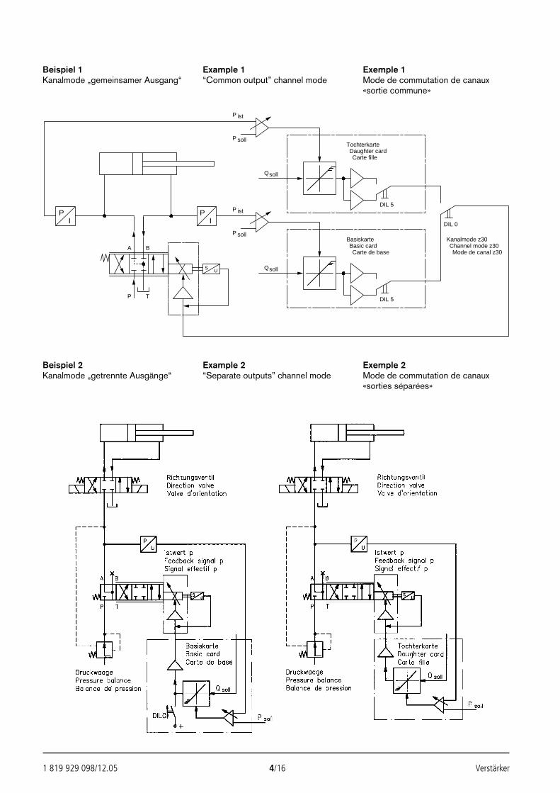
1 819 929 098/12.05 4/16 Verstärker
Beispiel 1Kanalmode „gemeinsamer Ausgang“
Example 1“Common output” channel mode
Exemple 1Mode de commutation de canaux«sortie commune»
A B
PI
PI
P ist
P soll
sollQ
P ist
P soll
sollQ
TochterkarteDaughter cardCarte fille
BasiskarteBasic cardCarte de base
S U
DIL 0
DIL 5
DIL 5
Kanalmode z30Channel mode z30Mode de canal z30
P T
Beispiel 2Kanalmode „getrennte Ausgänge“
Example 2“Separate outputs” channel mode
Exemple 2Mode de commutation de canaux«sorties séparées»
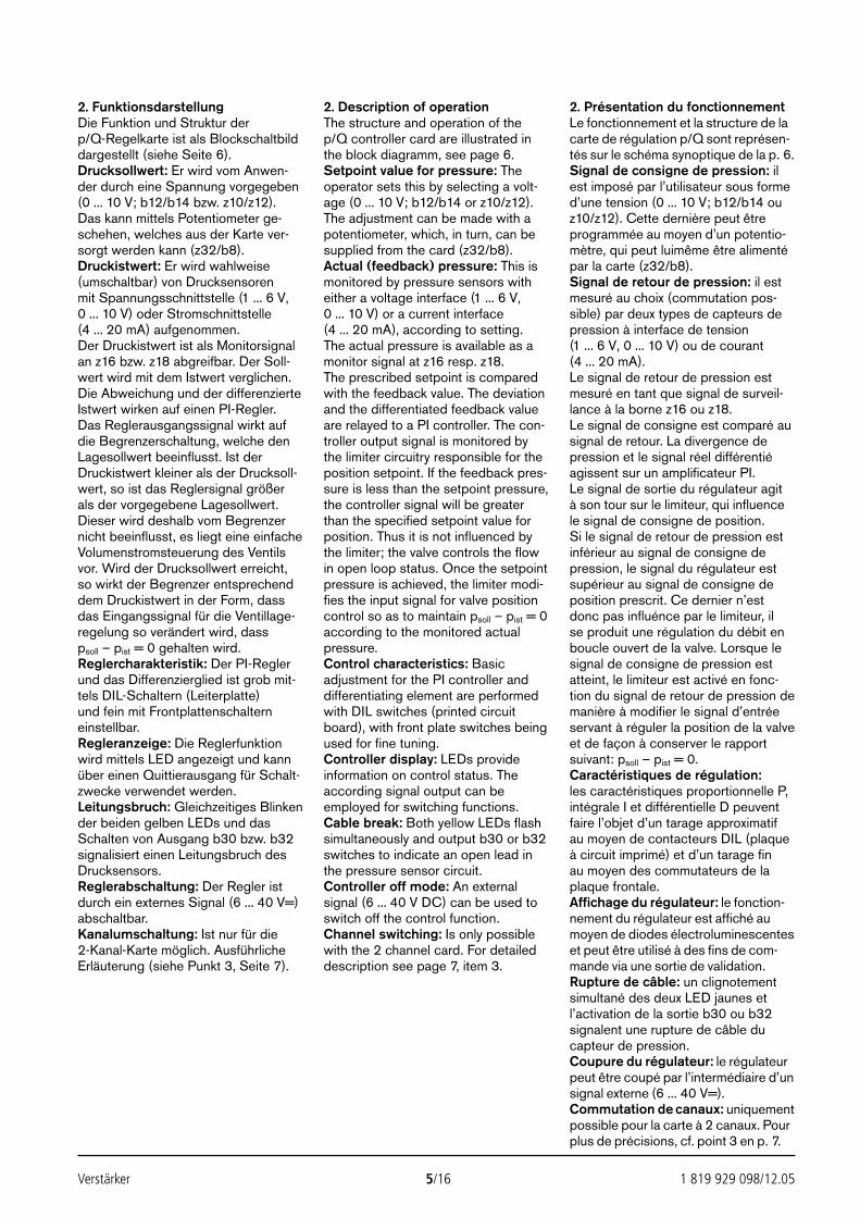
Verstärker 5/16 1 819 929 098/12.05
2. FunktionsdarstellungDie Funktion und Struktur der p/Q-Regelkarte ist als Blockschaltbilddargestellt (siehe Seite 6).Drucksollwert: Er wird vom Anwen-der durch eine Spannung vorgegeben(0 ... 10 V; b12/b14 bzw. z10/z12). Das kann mittels Potentiometer ge-schehen, welches aus der Karte ver-sorgt werden kann (z32/b8).Druckistwert: Er wird wahlweise(umschaltbar) von Drucksensoren mit Spannungsschnittstelle (1 ... 6 V,0 ... 10 V) oder Stromschnittstelle(4 ... 20 mA) aufgenommen.Der Druckistwert ist als Monitorsignalan z16 bzw. z18 abgreifbar. Der Soll-wert wird mit dem Istwert verglichen.Die Abweichung und der differenzierteIstwert wirken auf einen PI-Regler.Das Reglerausgangssignal wirkt aufdie Begrenzerschaltung, welche denLagesollwert beeinflusst. Ist derDruckistwert kleiner als der Drucksoll-wert, so ist das Reglersignal größerals der vorgegebene Lagesollwert.Dieser wird deshalb vom Begrenzernicht beeinflusst, es liegt eine einfacheVolumenstromsteuerung des Ventilsvor. Wird der Drucksollwert erreicht,so wirkt der Begrenzer entsprechenddem Druckistwert in der Form, dassdas Eingangssignal für die Ventillage-regelung so verändert wird, dass psoll – pist = 0 gehalten wird.Reglercharakteristik: Der PI-Reglerund das Differenzierglied ist grob mit-tels DIL-Schaltern (Leiterplatte)und fein mit Frontplattenschalterneinstellbar.Regleranzeige: Die Reglerfunktionwird mittels LED angezeigt und kannüber einen Quittierausgang für Schalt-zwecke verwendet werden.Leitungsbruch: Gleichzeitiges Blinkender beiden gelben LEDs und dasSchalten von Ausgang b30 bzw. b32signalisiert einen Leitungsbruch desDrucksensors.Reglerabschaltung: Der Regler istdurch ein externes Signal (6 ... 40 V=)abschaltbar.Kanalumschaltung: Ist nur für die 2-Kanal-Karte möglich. AusführlicheErläuterung (siehe Punkt 3, Seite 7).
2. Description of operationThe structure and operation of thep/Q controller card are illustrated inthe block diagramm, see page 6.Setpoint value for pressure: Theoperator sets this by selecting a volt-age (0 ... 10 V; b12/b14 or z10/z12).The adjustment can be made with apotentiometer, which, in turn, can besupplied from the card (z32/b8).Actual (feedback) pressure: This ismonitored by pressure sensors witheither a voltage interface (1 ... 6 V,0 ... 10 V) or a current interface(4 ... 20 mA), according to setting.The actual pressure is available as amonitor signal at z16 resp. z18.The prescribed setpoint is comparedwith the feedback value. The deviationand the differentiated feedback valueare relayed to a PI controller. The con-troller output signal is monitored bythe limiter circuitry responsible for theposition setpoint. If the feedback pres-sure is less than the setpoint pressure,the controller signal will be greaterthan the specified setpoint value forposition. Thus it is not influenced bythe limiter; the valve controls the flowin open loop status. Once the setpointpressure is achieved, the limiter modi-fies the input signal for valve positioncontrol so as to maintain psoll – pist = 0according to the monitored actualpressure.Control characteristics: Basicadjustment for the PI controller anddifferentiating element are performedwith DIL switches (printed circuitboard), with front plate switches beingused for fine tuning.Controller display: LEDs provideinformation on control status. Theaccording signal output can beemployed for switching functions.Cable break: Both yellow LEDs flashsimultaneously and output b30 or b32switches to indicate an open lead inthe pressure sensor circuit.Controller off mode: An externalsignal (6 ... 40 V DC) can be used toswitch off the control function.Channel switching: Is only possiblewith the 2 channel card. For detaileddescription see page 7, item 3.
2. Présentation du fonctionnementLe fonctionnement et la structure de lacarte de régulation p/Q sont représen-tés sur le schéma synoptique de la p. 6.Signal de consigne de pression: ilest imposé par l’utilisateur sous formed’une tension (0 ... 10 V; b12/b14 ouz10/z12). Cette dernière peut êtreprogrammée au moyen d’un potentio-mètre, qui peut luimême être alimentépar la carte (z32/b8).Signal de retour de pression: il estmesuré au choix (commutation pos-sible) par deux types de capteurs depression à interface de tension(1 ... 6 V, 0 ... 10 V) ou de courant (4 ... 20 mA).Le signal de retour de pression estmesuré en tant que signal de surveil-lance à la borne z16 ou z18.Le signal de consigne est comparé ausignal de retour. La divergence depression et le signal réel différentiéagissent sur un amplificateur PI. Le signal de sortie du régulateur agit à son tour sur le limiteur, qui influencele signal de consigne de position. Si le signal de retour de pression estinférieur au signal de consigne depression, le signal du régulateur estsupérieur au signal de consigne deposition prescrit. Ce dernier n’estdonc pas influénce par le limiteur, il se produit une régulation du débit enboucle ouvert de la valve. Lorsque lesignal de consigne de pression estatteint, le limiteur est activé en fonc-tion du signal de retour de pression demanière à modifier le signal d’entréeservant à réguler la position de la valveet de façon à conserver le rapportsuivant: psoll – pist = 0.Caractéristiques de régulation:les caractéristiques proportionnelle P,intégrale I et différentielle D peuventfaire l’objet d’un tarage approximatifau moyen de contacteurs DIL (plaqueà circuit imprimé) et d’un tarage fin au moyen des commutateurs de laplaque frontale.Affichage du régulateur: le fonction-nement du régulateur est affiché aumoyen de diodes électroluminescenteset peut être utilisé à des fins de com-mande via une sortie de validation.Rupture de câble: un clignotementsimultané des deux LED jaunes et l’activation de la sortie b30 ou b32signalent une rupture de câble du capteur de pression.Coupure du régulateur: le régulateurpeut être coupé par l’intermédiaire d’unsignal externe (6 ... 40 V=).Commutation de canaux: uniquementpossible pour la carte à 2 canaux. Pourplus de précisions, cf. point 3 en p. 7.
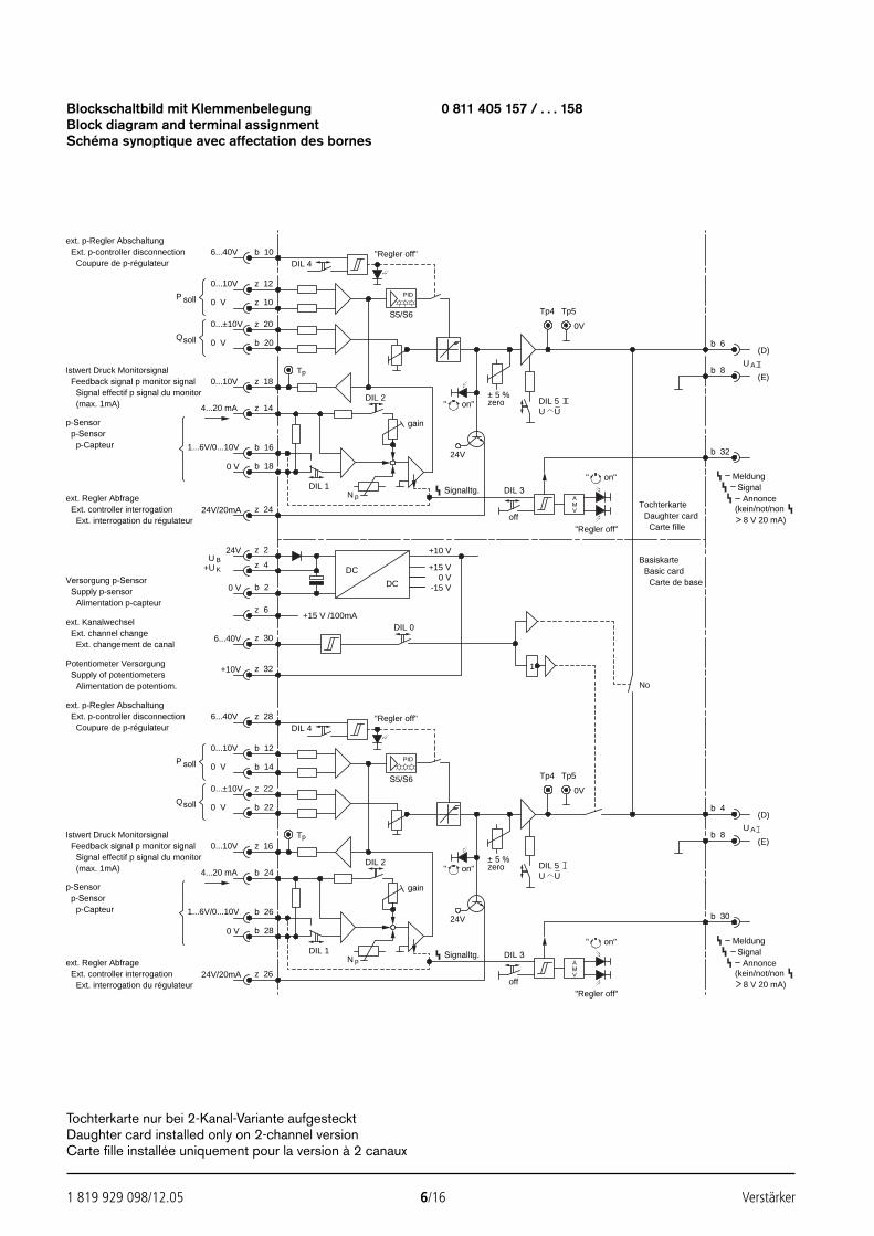
1 819 929 098/12.05 6/16 Verstärker
Blockschaltbild mit Klemmenbelegung 0 811 405 157 / . . . 158Block diagram and terminal assignmentSchéma synoptique avec affectation des bornes
6...40V
0...10V
0 V
0 V
DIL 4"Regler off"
PID
S5/S60V
± 5 %zero DIL 5
U U"
0...10V
4...20 mA
soll
DIL 2
Tp
"Regler off"
b 24
1...6V/0...10V
0 V
DIL 1pN DIL 3Signalltg.
24V
off
AMV
+15 V /100mADIL 0
+10 V
-15 V0 V
+15 V
on"
P soll
Q
Istwert Druck MonitorsignalFeedback signal p monitor signal
Signal effectif p signal du monitor(max. 1mA)
p-Capteur
" on"
DC
DC
24V/20mA
0 V b 2
24V z 2
z 4
z 6
6...40V z 30
+10V z 32
gain
Tp4 Tp5
AUb 8
(D)
(E)
TochterkarteDaughter card
Carte fille
Basic cardCarte de base
Basiskarte
MeldungSignal
Annonce(kein/not/non
8 V 20 mA)
1
0...±10V
BUK+U
ext. p-Regler AbschaltungExt. p-controller disconnection
ext. Regler AbfrageExt. controller interrogation
Ext. interrogation du régulateur
Supply p-sensorAlimentation p-capteur
ext. KanalwechselExt. channel change
Ext. changement de canal
Potentiometer VersorgungSupply of potentiometers
Alimentation de potentiom.
b 10
z 12
6...40V
0...10V
z 10
z 20
b 20
0 V
0 V
DIL 4"Regler off"
PID
S5/S60V
± 5 %zero DIL 5
U U"
0...10V
4...20 mA
soll
DIL 2
Tp
"Regler off"
z 18
z 14
1...6V/0...10V
0 V
b 16
b 18
DIL 1pN DIL 3Signalltg.
24V
off
AMV
on"
P soll
Q
Istwert Druck MonitorsignalFeedback signal p monitor signal
Signal effectif p signal du monitor(max. 1mA)
p-Capteur
" on"
24V/20mA z 24
gain
Tp4 Tp5
AU
b 6
b 8
(D)
(E)
b 32
MeldungSignal
Annonce(kein/not/non
8 V 20 mA)
0...±10V
ext. p-Regler AbschaltungExt. p-controller disconnection
ext. Regler AbfrageExt. controller interrogation
Ext. interrogation du régulateur
No
b 4
b 30
Coupure de p-régulateur
p-Sensorp-Sensor
z 28
b 12
b 14
z 22
b 22
z 16
b 26
b 28
z 26
p-Sensorp-Sensor
Coupure de p-régulateur
Versorgung p-Sensor
Tochterkarte nur bei 2-Kanal-Variante aufgestecktDaughter card installed only on 2-channel versionCarte fille installée uniquement pour la version à 2 canaux
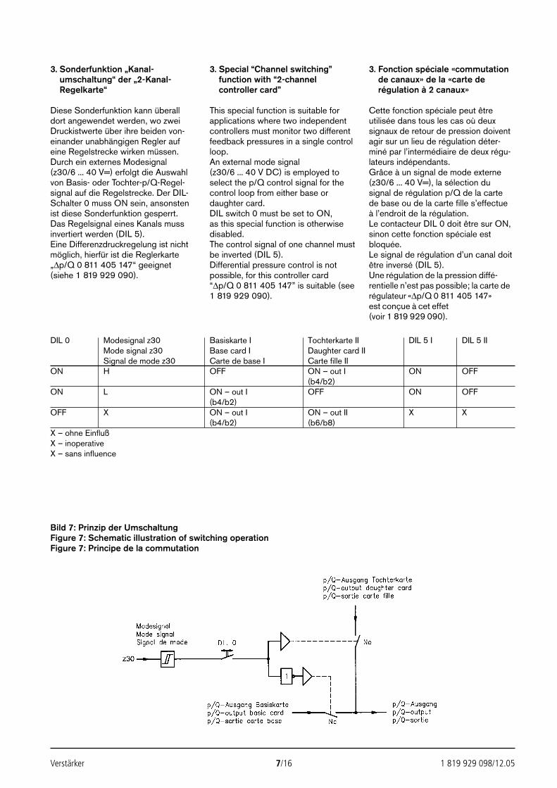
Verstärker 7/16 1 819 929 098/12.05
3. Sonderfunktion „Kanal-umschaltung“ der „2-Kanal-Regelkarte“
Diese Sonderfunktion kann überalldort angewendet werden, wo zweiDruckistwerte über ihre beiden von-einander unabhängigen Regler aufeine Regelstrecke wirken müssen.Durch ein externes Modesignal(z30/6 ... 40 V=) erfolgt die Auswahlvon Basis- oder Tochter-p/Q-Regel-signal auf die Regelstrecke. Der DIL-Schalter 0 muss ON sein, ansonstenist diese Sonderfunktion gesperrt.Das Regelsignal eines Kanals mussinvertiert werden (DIL 5).Eine Differenzdruckregelung ist nichtmöglich, hierfür ist die Reglerkarte„∆p/Q 0 811 405 147“ geeignet(siehe 1 819 929 090).
3. Special “Channel switching”function with “2-channelcontroller card”
This special function is suitable forapplications where two independentcontrollers must monitor two differentfeedback pressures in a single controlloop.An external mode signal(z30/6 ... 40 V DC) is employed toselect the p/Q control signal for thecontrol loop from either base ordaughter card.DIL switch 0 must be set to ON, as this special function is otherwisedisabled.The control signal of one channel mustbe inverted (DIL 5).Differential pressure control is notpossible, for this controller card “∆p/Q 0 811 405 147” is suitable (see1 819 929 090).
3. Fonction spéciale «commutationde canaux» de la «carte derégulation à 2 canaux»
Cette fonction spéciale peut êtreutilisée dans tous les cas où deuxsignaux de retour de pression doiventagir sur un lieu de régulation déter-miné par l’intermédiaire de deux régu-lateurs indépendants.Grâce à un signal de mode externe(z30/6 ... 40 V=), la sélection dusignal de régulation p/Q de la carte de base ou de la carte fille s’effectue à l’endroit de la régulation.Le contacteur DIL 0 doit être sur ON,sinon cette fonction spéciale estbloquée.Le signal de régulation d’un canal doitêtre inversé (DIL 5).Une régulation de la pression diffé-rentielle n’est pas possible; la carte derégulateur «∆p/Q 0 811 405 147»est conçue à cet effet (voir 1 819 929 090).
DIL 0 Modesignal z30 Basiskarte I Tochterkarte II DIL 5 I DIL 5 IIMode signal z30 Base card I Daughter card IISignal de mode z30 Carte de base I Carte fille II
ON H OFF ON – out I ON OFF(b4/b2)
ON L ON – out I OFF ON OFF(b4/b2)
OFF X ON – out I ON – out II X X(b4/b2) (b6/b8)
X – ohne EinflußX – inoperativeX – sans influence
Bild 7: Prinzip der UmschaltungFigure 7: Schematic illustration of switching operationFigure 7: Principe de la commutation
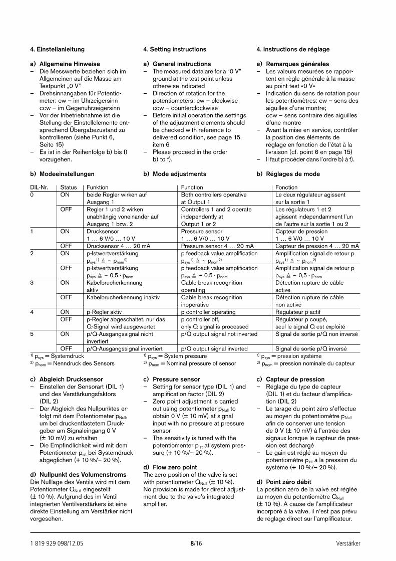
1 819 929 098/12.05 8/16 Verstärker
4. Einstellanleitung
a) Allgemeine Hinweise– Die Messwerte beziehen sich im
Allgemeinen auf die Masse amTestpunkt „0 V“
– Drehsinnangaben für Potentio-meter: cw – im Uhrzeigersinnccw – im Gegenuhrzeigersinn
– Vor der Inbetriebnahme ist dieStellung der Einstellelemente ent-sprechend Übergabezustand zukontrollieren (siehe Punkt 6, Seite 15)
– Es ist in der Reihenfolge b) bis f)vorzugehen.
b) Modeeinstellungen
4. Setting instructions
a) General instructions– The measured data are for a “0 V”
ground at the test point unlessotherwise indicated
– Direction of rotation for thepotentiometers: cw – clockwiseccw – counterclockwise
– Before initial operation the settingsof the adjustment elements shouldbe checked with reference todelivered condition, see page 15,item 6
– Please proceed in the order b) to f).
b) Mode adjustments
4. Instructions de réglage
a) Remarques générales– Les valeurs mesurées se rappor-
tent en règle générale à la masseau point test «0 V»
– Indication du sens de rotation pourles potentiomètres: cw – sens desaiguilles d’une montre; ccw – sens contraire des aiguillesd’une montre
– Avant la mise en service, contrôlerla position des éléments deréglage en fonction de l’état à lalivraison (cf. point 6 en page 15)
– Il faut procéder dans l’ordre b) à f).
b) Réglages de mode
c) Abgleich Drucksensor– Einstellen der Sensorart (DIL 1)
und des Verstärkungsfaktors(DIL 2)
– Der Abgleich des Nullpunktes er-folgt mit dem Potentiometer pNull,um bei druckentlastetem Druck-geber am Signaleingang 0 V(± 10 mV) zu erhalten
– Die Empfindlichkeit wird mit demPotentiometer pist bei Systemdruckabgeglichen (+ 10 %/– 20 %).
d) Nullpunkt des VolumenstromsDie Nulllage des Ventils wird mit demPotentiometer QNull eingestellt(± 10 %). Aufgrund des im Ventilintegrierten Ventilverstärkers ist einedirekte Einstellung am Verstärker nichtvorgesehen.
c) Pressure sensor– Setting for sensor type (DIL 1) and
amplification factor (DIL 2)– Zero point adjustment is carried
out using potentiometer pNull toobtain 0 V (± 10 mV) at signalinput with no pressure at pressuresensor
– The sensitivity is tuned with thepotentiomenter pist at system pres-sure (+ 10 %/– 20 %).
d) Flow zero pointThe zero position of the valve is setwith potentiometer QNull (± 10 %). No provision is made for direct adjust-ment due to the valve’s integratedamplifier.
c) Capteur de pression– Réglage du type de capteur
(DIL 1) et du facteur d’amplifica-tion (DIL 2)
– Le tarage du point zéro s’effectueau moyen du potentiomètre pNull
afin de conserver une tension de 0 V (± 10 mV) à l’entrée dessignaux lorsque le capteur de pres-sion est déchargé
– Le gain est réglé au moyen dupotentiomètre pist a la pression dusystème (+ 10 %/– 20 %).
d) Point zéro débitLa position zéro de la valve est régléeau moyen du potentiomètre QNull
(± 10 %). A cause de l’amplificateurincorporé à la valve, il n’est pas prévude réglage direct sur l’amplificateur.
DIL-Nr. Status Funktion Function Fonction0 ON beide Regler wirken auf Both controllers operative Le deux régulateur agissent
Ausgang 1 at Output 1 sur la sortie 1OFF Regler 1 und 2 wirken Controllers 1 and 2 operate Les régulateurs 1 et 2
unabhängig voneinander auf independently at agissent independamment l’unAusgang 1 bzw. 2 Output 1 or 2 de l’autre sur la sortie 1 ou 2
1 ON Drucksensor Pressure sensor Capteur de pression 1 … 6 V/0 … 10 V 1 … 6 V/0 … 10 V 1 … 6 V/0 … 10 V
OFF Drucksensor 4 … 20 mA Pressure sensor 4 … 20 mA Capteur de pression 4 … 20 mA2 ON p-Istwertverstärkung p feedback value amplification Amplification signal de retour p
psys1) ~ pnom
2) psys1) ~ pnom
2) psys1) ~ pnom
2)
OFF p-Istwertverstärkung p feedback value amplification Amplification signal de retour ppsys ~ 0,5 · pnom psys ~ 0.5 · pnom psys ~ 0,5 · pnom
3 ON Kabelbrucherkennung Cable break recognition Détection rupture de câble aktiv operating active
OFF Kabelbrucherkennung inaktiv Cable break recognition Détection rupture de câbleinoperative non active
4 ON p-Regler aktiv p controller operating Régulateur p actifOFF p-Regler abgeschaltet, nur das p controller off, Régulateur p coupé,
Q-Signal wird ausgewertet only Q signal is processed seul le signal Q est exploité5 ON p/Q-Ausgangssignal nicht p/Q output signal not inverted Signal de sortie p/Q non inversé
invertiertOFF p/Q-Ausgangssignal invertiert p/Q output signal inverted Signal de sortie p/Q inversé
1) psys = Systemdruck 1) psys = System pressure 1) psys = pression système2) pnom = Nenndruck des Sensors 2) pnom = Nominal pressure of sensor 2) pnom = pression nominale du capteur
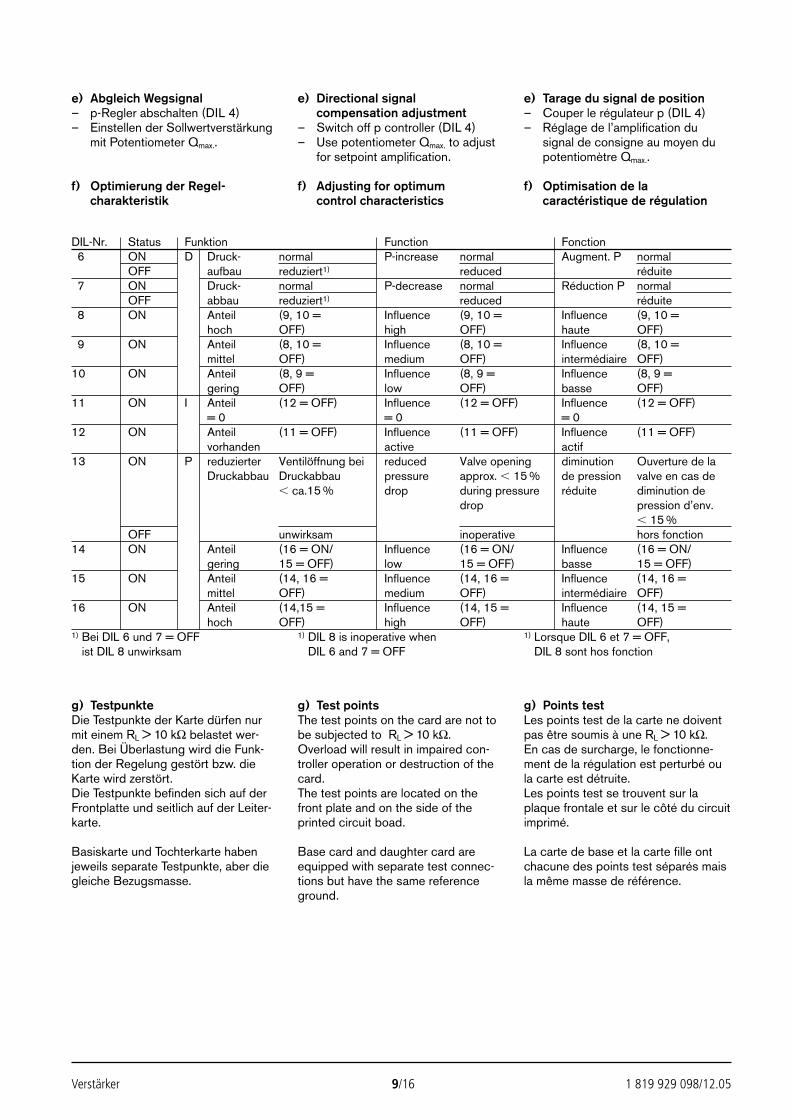
DIL-Nr. Status Funktion Function Fonction6 ON D Druck- normal P-increase normal Augment. P normal
OFF aufbau reduziert1) reduced réduite7 ON Druck- normal P-decrease normal Réduction P normal
OFF abbau reduziert1) reduced réduite8 ON Anteil (9, 10 = Influence (9, 10 = Influence (9, 10 =
hoch OFF) high OFF) haute OFF)9 ON Anteil (8, 10 = Influence (8, 10 = Influence (8, 10 =
mittel OFF) medium OFF) intermédiaire OFF)10 ON Anteil (8, 9 = Influence (8, 9 = Influence (8, 9 =
gering OFF) low OFF) basse OFF)11 ON I Anteil (12 = OFF) Influence (12 = OFF) Influence (12 = OFF)
= 0 = 0 = 012 ON Anteil (11 = OFF) Influence (11 = OFF) Influence (11 = OFF)
vorhanden active actif13 ON P reduzierter Ventilöffnung bei reduced Valve opening diminution Ouverture de la
Druckabbau Druckabbau pressure approx. 15 % de pression valve en cas de ca.15 % drop during pressure réduite diminution de
drop pression d’env. 15 %
OFF unwirksam inoperative hors fonction14 ON Anteil (16 = ON/ Influence (16 = ON/ Influence (16 = ON/
gering 15 = OFF) low 15 = OFF) basse 15 = OFF)15 ON Anteil (14, 16 = Influence (14, 16 = Influence (14, 16 =
mittel OFF) medium OFF) intermédiaire OFF)16 ON Anteil (14,15 = Influence (14, 15 = Influence (14, 15 =
hoch OFF) high OFF) haute OFF)1) Bei DIL 6 und 7 = OFF 1) DIL 8 is inoperative when 1) Lorsque DIL 6 et 7 = OFF,1) ist DIL 8 unwirksam 1) DIL 6 and 7 = OFF 1) DIL 8 sont hos fonction
Verstärker 9/16 1 819 929 098/12.05
e) Abgleich Wegsignal– p-Regler abschalten (DIL 4)– Einstellen der Sollwertverstärkung
mit Potentiometer Qmax..
f) Optimierung der Regel-charakteristik
e) Directional signalcompensation adjustment
– Switch off p controller (DIL 4)– Use potentiometer Qmax. to adjust
for setpoint amplification.
f) Adjusting for optimumcontrol characteristics
e) Tarage du signal de position– Couper le régulateur p (DIL 4)– Réglage de l’amplification du
signal de consigne au moyen dupotentiomètre Qmax..
f) Optimisation de lacaractéristique de régulation
g) TestpunkteDie Testpunkte der Karte dürfen nurmit einem RL > 10 kΩ belastet wer-den. Bei Überlastung wird die Funk-tion der Regelung gestört bzw. dieKarte wird zerstört.Die Testpunkte befinden sich auf derFrontplatte und seitlich auf der Leiter-karte.
g) Test pointsThe test points on the card are not tobe subjected to RL > 10 kΩ.Overload will result in impaired con-troller operation or destruction of thecard.The test points are located on thefront plate and on the side of theprinted circuit boad.
g) Points testLes points test de la carte ne doiventpas être soumis à une RL > 10 kΩ.En cas de surcharge, le fonctionne-ment de la régulation est perturbé oula carte est détruite.Les points test se trouvent sur laplaque frontale et sur le côté du circuitimprimé.
Basiskarte und Tochterkarte haben jeweils separate Testpunkte, aber diegleiche Bezugsmasse.
Base card and daughter card areequipped with separate test connec-tions but have the same referenceground.
La carte de base et la carte fille ontchacune des points test séparés maisla même masse de référence.
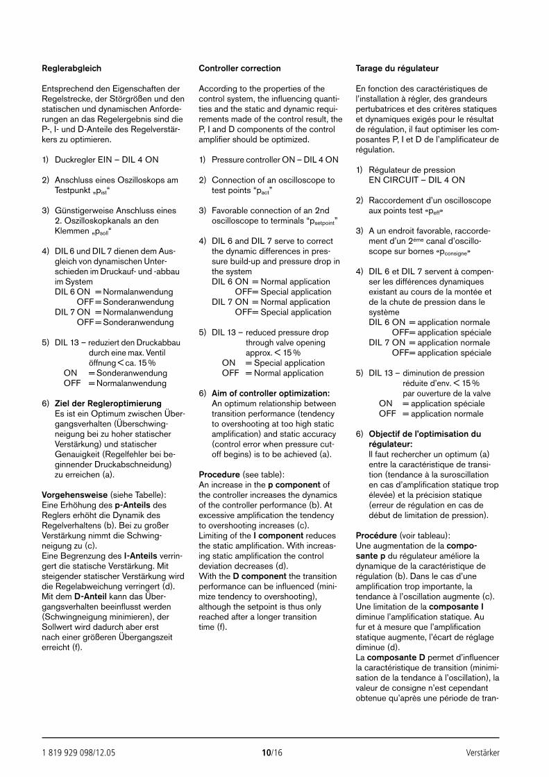
1 819 929 098/12.05 10/16 Verstärker
Reglerabgleich
Entsprechend den Eigenschaften derRegelstrecke, der Störgrößen und denstatischen und dynamischen Anforde-rungen an das Regelergebnis sind dieP-, I- und D-Anteile des Regelverstär-kers zu optimieren.
1) Duckregler EIN – DIL 4 ON
2) Anschluss eines Oszilloskops amTestpunkt „pist“
3) Günstigerweise Anschluss eines 2. Oszilloskopkanals an denKlemmen „psoll“
4) DIL 6 und DIL 7 dienen dem Aus-gleich von dynamischen Unter-schieden im Druckauf- und -abbauim SystemDIL 6 ON = Normalanwendung
OFF = SonderanwendungDIL 7 ON = Normalanwendung
OFF = Sonderanwendung
5) DIL 13 – reduziert den Druckabbaudurch eine max. Ventilöffnung < ca. 15 %
DIL 6 ON = SonderanwendungOFF = Normalanwendung
6) Ziel der RegleroptimierungEs ist ein Optimum zwischen Über-gangsverhalten (Überschwing-neigung bei zu hoher statischerVerstärkung) und statischerGenauigkeit (Regelfehler bei be-ginnender Druckabschneidung) zu erreichen (a).
Vorgehensweise (siehe Tabelle):Eine Erhöhung des p-Anteils desReglers erhöht die Dynamik desRegelverhaltens (b). Bei zu großerVerstärkung nimmt die Schwing-neigung zu (c). Eine Begrenzung des I-Anteils verrin-gert die statische Verstärkung. Mitsteigender statischer Verstärkung wirddie Regelabweichung verringert (d). Mit dem D-Anteil kann das Über-gangsverhalten beeinflusst werden(Schwingneigung minimieren), derSollwert wird dadurch aber erst nach einer größeren Übergangszeiterreicht (f).
Controller correction
According to the properties of thecontrol system, the influencing quanti-ties and the static and dynamic requi-rements made of the control result, theP, I and D components of the controlamplifier should be optimized.
1) Pressure controller ON – DIL 4 ON
2) Connection of an oscilloscope totest points “pact”
3) Favorable connection of an 2ndoscilloscope to terminals “psetpoint”
4) DIL 6 and DIL 7 serve to correctthe dynamic differences in pres-sure build-up and pressure drop inthe systemDIL 6 ON = Normal application
OFF= Special applicationDIL 7 ON = Normal application
OFF= Special application
5) DIL 13 – reduced pressure dropthrough valve opening approx. < 15 %
DIL 6 ON = Special applicationOFF = Normal application
6) Aim of controller optimization:An optimum relationship betweentransition performance (tendencyto overshooting at too high staticamplification) and static accuracy(control error when pressure cut-off begins) is to be achieved (a).
Procedure (see table):An increase in the p component ofthe controller increases the dynamicsof the controller performance (b). Atexcessive amplification the tendencyto overshooting increases (c). Limiting of the I component reducesthe static amplification. With increas-ing static amplification the controldeviation decreases (d).With the D component the transitionperformance can be influenced (mini-mize tendency to overshooting),although the setpoint is thus onlyreached after a longer transition time (f).
Tarage du régulateur
En fonction des caractéristiques del’installation à régler, des grandeurspertubatrices et des critères statiqueset dynamiques exigés pour le résultatde régulation, il faut optimiser les com-posantes P, I et D de l’amplificateur derégulation.
1) Régulateur de pressionEN CIRCUIT – DIL 4 ON
2) Raccordement d’un oscilloscopeaux points test «peff»
3) A un endroit favorable, raccorde-ment d’un 2éme canal d’oscillo-scope sur bornes «pconsigne»
4) DIL 6 et DIL 7 servent à compen-ser les différences dynamiquesexistant au cours de la montée etde la chute de pression dans lesystèmeDIL 6 ON = application normale
OFF= application spécialeDIL 7 ON = application normale
OFF= application spéciale
5) DIL 13 – diminution de pressionréduite d’env. < 15 %par ouverture de la valve
DIL 6 ON = application spécialeOFF = application normale
6) Objectif de l’optimisation durégulateur:Il faut rechercher un optimum (a)entre la caractéristique de transi-tion (tendance à la suroscillationen cas d’amplification statique tropélevée) et la précision statique(erreur de régulation en cas dedébut de limitation de pression).
Procédure (voir tableau):Une augmentation de la compo-sante p du régulateur améliore ladynamique de la caractéristique derégulation (b). Dans le cas d’uneamplification trop importante, latendance à l’oscillation augmente (c).Une limitation de la composante Idiminue l’amplification statique. Au fur et à mesure que l’amplificationstatique augmente, l’écart de réglagediminue (d). La composante D permet d’influencerla caractéristique de transition (minimi-sation de la tendance à l’oscillation), lavaleur de consigne n’est cependantobtenue qu’après une période de tran-
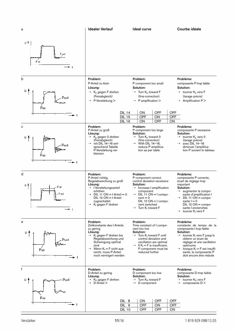
Verstärker 11/16 1 819 929 098/12.05
Problem:P-Anteil zu kleinLösung: Kp gegen F drehen
(Feinabgleich) P-Verstärkung >
Problem:P component too smallSolution: Turn Kp toward F
(fine-correction) P amplification >
Problème:composante P trop faibleSolution: tourner Kp vers F
(tarage précis) Amplification P >
Problem:P-Anteil zu großLösung: Kp gegen 0 drehen
(Feinabgleich) mit DIL 14–16 ent-
sprechend TabelleP-Verstärkung ver-kleinern
Problem:P component too largeSolution: Turn Kp toward 0
(fine-correction) With DIL 14–16,
reduce P amplifica-tion as per table
Problème:composante P excessiveSolution: tourner Kp vers 0
(tarage précis) avec DIL 14–16
diminuer l’amplifica-tion P suivant le tableau
Problem:P-Anteil richtig,Regelabweichung zu großLösung: I-Verstärkungsanteil
erhöhen DIL 11 ON = I-Anteil = 0
DIL 12 ON = I-Anteilzugeschaltet
KI gegen F drehen
Problem:P component correct,control deviation excessiveSolution: Increase I amplification
component DIL 11 ON = I compo-
nent = 0DIL 12 ON = I compo-nent switched
Turn KI toward F
Problème:composante P correcte,écart de réglage tropimportantSolution: augmenter la compo-
sante d’amplification I DIL 11 ON = compo-
sante I = 0DIL 12 ON = compo-sante I enclenchés
tourner KI vers F
Problem:Zeitkonstante des I-Anteilszu geringLösung: KI gegen F drehen bis
Regelabweichung undSchwingung optimalsind
Wenn KI = F nicht aus-reicht, muss P-Anteilnoch verringert werden
Problem:Time constant of I compo-nent too lowSolution: Turn KI toward F until
control deviation andoscillation are optimal
If KI = F is insufficient, P component must bereduced further
Problème:constante de temps de lacomposante I trop faibleSolution: tourner KI vers F jusqu’à
obtenir un écart deréglage et une oscillationoptimums
lorsque KI = F est insuffi-sante, la composante Pdoit encore être réduite
Problem:D-Anteil zu geringLösung: KD gegen F drehen D-Anteil >
Problem:D component too lowSolution: Turn KD toward F D component
Problème:composante D trop faibleSolution: tourner KD vers F composante D >
a
b
c
d
e
f
DIL 14 ON OFF OFFDIL 15 OFF ON OFFDIL 16 ON OFF ON
DIL 8 ON OFF OFFDIL 9 OFF ON OFFDIL 10 OFF OFF ON
Idealer Verlauf Ideal curve Courbe idéale
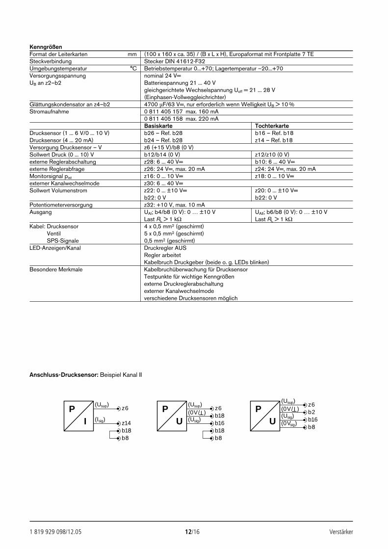
1 819 929 098/12.05 12/16 Verstärker
KenngrößenFormat der Leiterkarten mm (100 x 160 x ca. 35) / (B x L x H), Europaformat mit Frontplatte 7 TESteckverbindung Stecker DIN 41612-F32Umgebungstemperatur °C Betriebstemperatur 0...+70; Lagertemperatur –20...+70Versorgungsspannung nominal 24 V=UB an z2–b2 Batteriespannung 21 ... 40 V
gleichgerichtete Wechselspannung Ueff = 21 ... 28 V(Einphasen-Vollweggleichrichter)
Glättungskondensator an z4–b2 4700 µF/63 V=, nur erforderlich wenn Welligkeit UB > 10 %Stromaufnahme 0 811 405 157 max. 160 mA
0 811 405 158 max. 220 mABasiskarte Tochterkarte
Drucksensor (1 ... 6 V/0 ... 10 V) b26 – Ref. b28 b16 – Ref. b18Drucksensor (4 ... 20 mA) b24 – Ref. b28 z14 – Ref. b18Versorgung Drucksensor – V z6 (+15 V)/b8 (0 V)Sollwert Druck (0 ... 10) V b12/b14 (0 V) z12/z10 (0 V)externe Reglerabschaltung z28: 6 ... 40 V= b10: 6 ... 40 V=externe Reglerabfrage z26: 24 V=, max. 20 mA z24: 24 V=, max. 20 mAMonitorsignal pist z16: 0 ... 10 V= z18: 0 ... 10 V=externer Kanalwechselmode z30: 6 ... 40 V=Sollwert Volumenstrom z22: 0 ... ±10 V= z20: 0 ... ±10 V=
b22: 0 V b22: 0 VPotentiometerversorgung z32: +10 V, max. 10 mAAusgang UAI; b4/b8 (0 V): 0 … ±10 V UAII; b6/b8 (0 V): 0 … ±10 V
Last RL > 1 kΩ Last RL > 1 kΩKabel: Drucksensor 4 x 0,5 mm2 (geschirmt)Kabel: Ventil 5 x 0,5 mm2 (geschirmt)Kabel: SPS-Signale 0,5 mm2 (geschirmt)LED-Anzeigen/Kanal Druckregler AUS
Regler arbeitetKabelbruch Druckgeber (beide o. g. LEDs blinken)
Besondere Merkmale Kabelbruchüberwachung für DrucksensorTestpunkte für wichtige Kenngrößenexterne Druckreglerabschaltungexterner Kanalwechselmodeverschiedene Drucksensoren möglich
(Usup)PI
z6
(Isig) z14
(Usup)PU
z6(0V/ ) b18(Usig) b16
b18b8
b18b8
(Usup)
PU
z6(0V/ ) b2(Usig) b16(0Vsig)
b8
Anschluss-Drucksensor: Beispiel Kanal II
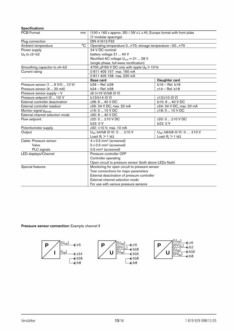
Verstärker 13/16 1 819 929 098/12.05
SpecificationsPCB Format mm (100 x 160 x approx. 35) / (W x L x H), Europe format with front plate
(7 modular spacings)Plug connection DIN 41612-F32Ambient temperature °C Operating temperature 0...+70; storage temperature –20...+70Power supply 24 V DC nominal UB to z2–b2 battery voltage 21 ... 40 V
Rectified AC voltage Urms = 21 ... 28 V(single phase, full-wave rectification)
Smoothing capacitor to z4–b2 4700 µF/63 V DC only with ripple UB > 10 %Current rating 0 811 405 157 max. 160 mA
0 811 405 158 max. 220 mABase card Daughter card
Pressure sensor (1 ... 6 V/0 ... 10 V) b26 – Ref. b28 b16 – Ref. b18Pressure sensor (4 ... 20 mA) b24 – Ref. b28 z14 – Ref. b18Pressure sensor supply – V z6 (+15 V)/b8 (0 V)Pressure setpoint (0 ... 10) V b12/b14 (0 V) z12/z10 (0 V)External controller deactivation z28: 6 ... 40 V DC b10: 6 ... 40 V DCExternal controller readout z26: 24 V DC, max. 20 mA z24: 24 V DC, max. 20 mAMonitor signal pactual z16: 0 ... 10 V DC z18: 0 ... 10 V DCExternal channel selection mode z30: 6 ... 40 V DCFlow setpoint z22: 0 ... ±10 V DC z20: 0 ... ±10 V DC
b22: 0 V b22: 0 VPotentiometer supply z32: +10 V, max. 10 mAOutput UAI; b4/b8 (0 V): 0 … ±10 V UAII; b6/b8 (0 V): 0 … ±10 V
Load RL > 1 kΩ Load RL > 1 kΩCable: Pressure sensor 4 x 0.5 mm2 (screened)Cable: Valve 5 x 0.5 mm2 (screened)Cable: PLC signals 0.5 mm2 (screened)LED displays/Channel Pressure controller OFF
Controller operatingOpen circuit to pressure sensor (both above LEDs flash)
Special features Monitoring for open circuit to pressure sensorTest connections for major parametersExternal deactivation of pressure controllerExternal channel selection modeFor use with various pressure sensors
(Usup)PI
z6
(Isig) z14
(Usup)PU
z6(0V/ ) b18(Usig) b16
b18b8
b18b8
(Usup)
PU
z6(0V/ ) b2(Usig) b16(0Vsig)
b8
Pressure sensor connection: Example channel II
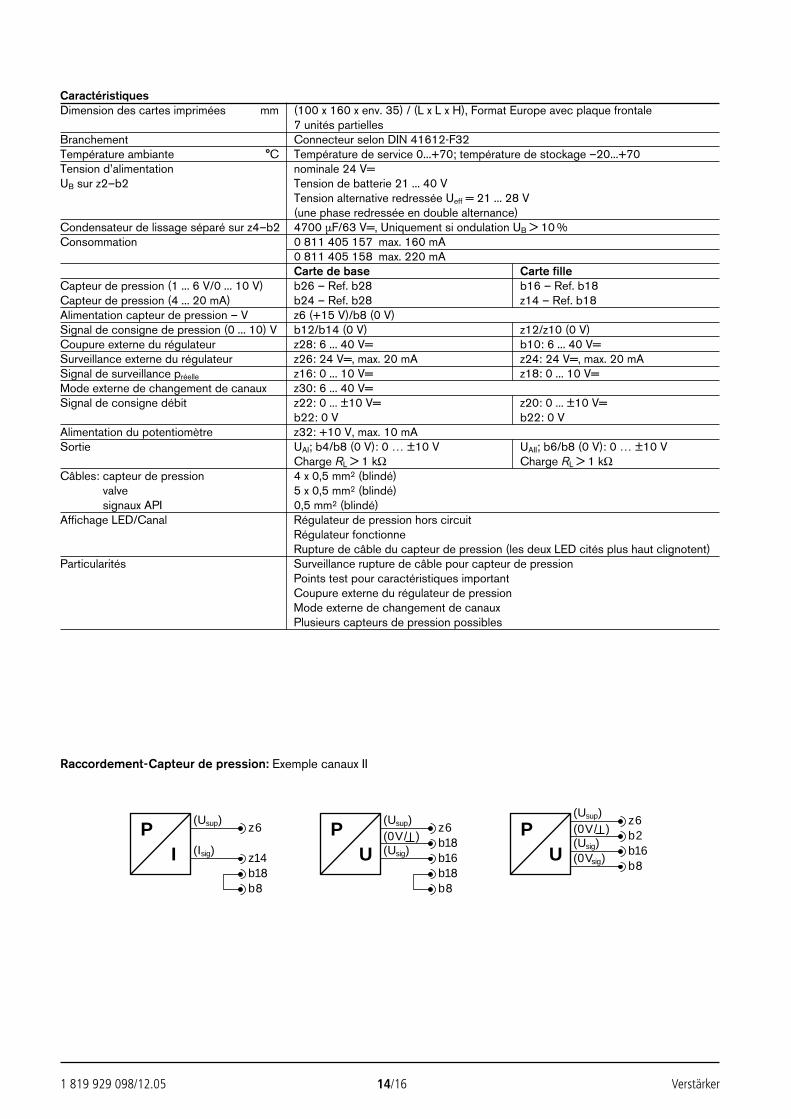
1 819 929 098/12.05 14/16 Verstärker
CaractéristiquesDimension des cartes imprimées mm (100 x 160 x env. 35) / (L x L x H), Format Europe avec plaque frontale
7 unités partiellesBranchement Connecteur selon DIN 41612-F32Température ambiante °C Température de service 0...+70; température de stockage –20...+70Tension d’alimentation nominale 24 V=UB sur z2–b2 Tension de batterie 21 ... 40 V
Tension alternative redressée Ueff = 21 ... 28 V(une phase redressée en double alternance)
Condensateur de lissage séparé sur z4–b2 4700 µF/63 V=, Uniquement si ondulation UB > 10 %Consommation 0 811 405 157 max. 160 mA
0 811 405 158 max. 220 mACarte de base Carte fille
Capteur de pression (1 ... 6 V/0 ... 10 V) b26 – Ref. b28 b16 – Ref. b18Capteur de pression (4 ... 20 mA) b24 – Ref. b28 z14 – Ref. b18Alimentation capteur de pression – V z6 (+15 V)/b8 (0 V)Signal de consigne de pression (0 ... 10) V b12/b14 (0 V) z12/z10 (0 V)Coupure externe du régulateur z28: 6 ... 40 V= b10: 6 ... 40 V=Surveillance externe du régulateur z26: 24 V=, max. 20 mA z24: 24 V=, max. 20 mASignal de surveillance préelle z16: 0 ... 10 V= z18: 0 ... 10 V=Mode externe de changement de canaux z30: 6 ... 40 V=Signal de consigne débit z22: 0 ... ±10 V= z20: 0 ... ±10 V=
b22: 0 V b22: 0 VAlimentation du potentiomètre z32: +10 V, max. 10 mASortie UAI; b4/b8 (0 V): 0 … ±10 V UAII; b6/b8 (0 V): 0 … ±10 V
Charge RL > 1 kΩ Charge RL > 1 kΩCâbles: capteur de pression 4 x 0,5 mm2 (blindé)Cables: valve 5 x 0,5 mm2 (blindé)Cables: signaux API 0,5 mm2 (blindé)Affichage LED/Canal Régulateur de pression hors circuit
Régulateur fonctionneRupture de câble du capteur de pression (les deux LED cités plus haut clignotent)
Particularités Surveillance rupture de câble pour capteur de pressionPoints test pour caractéristiques importantCoupure externe du régulateur de pressionMode externe de changement de canauxPlusieurs capteurs de pression possibles
(Usup)PI
z6
(Isig) z14
(Usup)PU
z6(0V/ ) b18(Usig) b16
b18b8
b18b8
(Usup)
PU
z6(0V/ ) b2(Usig) b16(0Vsig)
b8
Raccordement-Capteur de pression: Exemple canaux II

Verstärker 15/16 1 819 929 098/12.05
6. EinstelltabelleSetting tableTableau de réglage
DIL 16…0 ⎧⎪⎪⎪⎪⎨⎪⎪⎪⎪⎩
TP 4 TP 5
BasiskarteBase cardCarte de baseEingestellt von RexrothSet by HydraulikRéglé parDatum LieferzustandDate State of deliveryDate Etat de livraisonDIL 0 OFFDIL 1 OFFDIL 2 ONDIL 3 ONDIL 4 ONDIL 5 OFFDIL 6 OFFDIL 7 OFFDIL 8 OFFDIL 9 OFFDIL 10 OFFDIL 11 OFFDIL 12 OFFDIL 13 OFFDIL 14 OFFDIL 15 ONDIL 16 OFFHEX KP BHEX KI 1HEX KD D
DIL
-Sch
alte
r / S
witc
h /
Con
tact
eur
HE
X-C
OD
E
* Tochterkarte* Daughter card* Carte filleEingestellt von RexrothSet by HydraulikRéglé parDatum LieferzustandDate State of deliveryDate Etat de livraisonDIL 0 OFFDIL 1 OFFDIL 2 ONDIL 3 ONDIL 4 ONDIL 5 OFFDIL 6 OFFDIL 7 ONDIL 8 OFFDIL 9 OFFDIL 10 OFFDIL 11 OFFDIL 12 OFFDIL 13 OFFDIL 14 OFFDIL 15 ONDIL 16 OFFHEX KP 3HEX KI 9HEX KD 5
* nur bei 2-Kanal-Variante* 2-channel version only* uniquement pour la version à 2 canaux
DIL
-Sch
alte
r / S
witc
h /
Con
tact
eur
HE
X-C
OD
E
HEXCODE-SchalterHEXCODE-SwitchHEXCODE-Contacteur
DIL-SchalterDIL-SwitchDIL-Contacteur
1
9
D 5
TP 4: UA
TP 5: 0 V

Bosch Rexroth AGHydraulics
D-97813 Lohr am MainZum Eisengießer 1 D-97816 Lohr am MainTelefon 0 93 52/18-0Telefax 0 93 52/18-23 58 Telex 6 89 418-0eMail [email protected] www.boschrexroth.de
1 819 929 098/12.05 16/16 Verstärker
© Alle Rechte bei Bosch Rexroth AG, auch für den Fall von Schutzrechtsanmeldungen.Jede Verfügungsbefugnis, wie Kopier- und Weitergaberecht, bei uns.Die angegebenen Daten dienen allein der Produktbeschreibung. Eine Aussage übereine bestimmte Beschaffenheit oder eine Eignung für einen bestimmten Einsatzzweckkann aus unseren Angaben nicht abgeleitet werden. Die Angaben entbinden denVerwender nicht von eigenen Beurteilungen und Prüfungen. Es ist zu beachten, dassunsere Produkte einem natürlichen Verschleiß- und Alterungsprozess unterliegen.
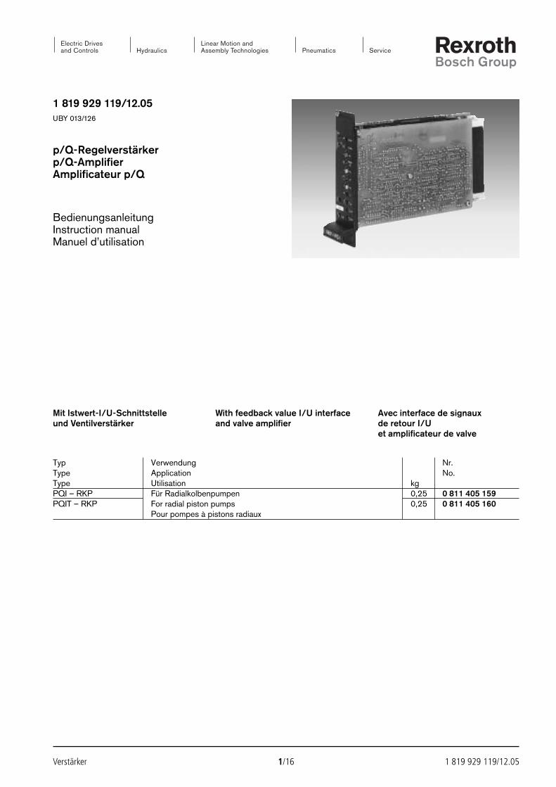
1 819 929 119/12.05UBY 013/126
p/Q-Regelverstärkerp/Q-AmplifierAmplificateur p/Q
BedienungsanleitungInstruction manualManuel d’utilisation
Verstärker 1/16 1 819 929 119/12.05
Typ Verwendung Nr.Type Application No.Type Utilisation kgPQI – RKP Für Radialkolbenpumpen 0,25 0 811 405 159PQIT – RKP For radial piston pumps 0,25 0 811 405 160
Pour pompes à pistons radiaux
Mit Istwert-I/U-Schnittstelleund Ventilverstärker
With feedback value I/U interfaceand valve amplifier
Avec interface de signaux de retour I/Uet amplificateur de valve
2592_UBY013_126_001-016.qxd 30.11.2005 9:49 Uhr Seite 1
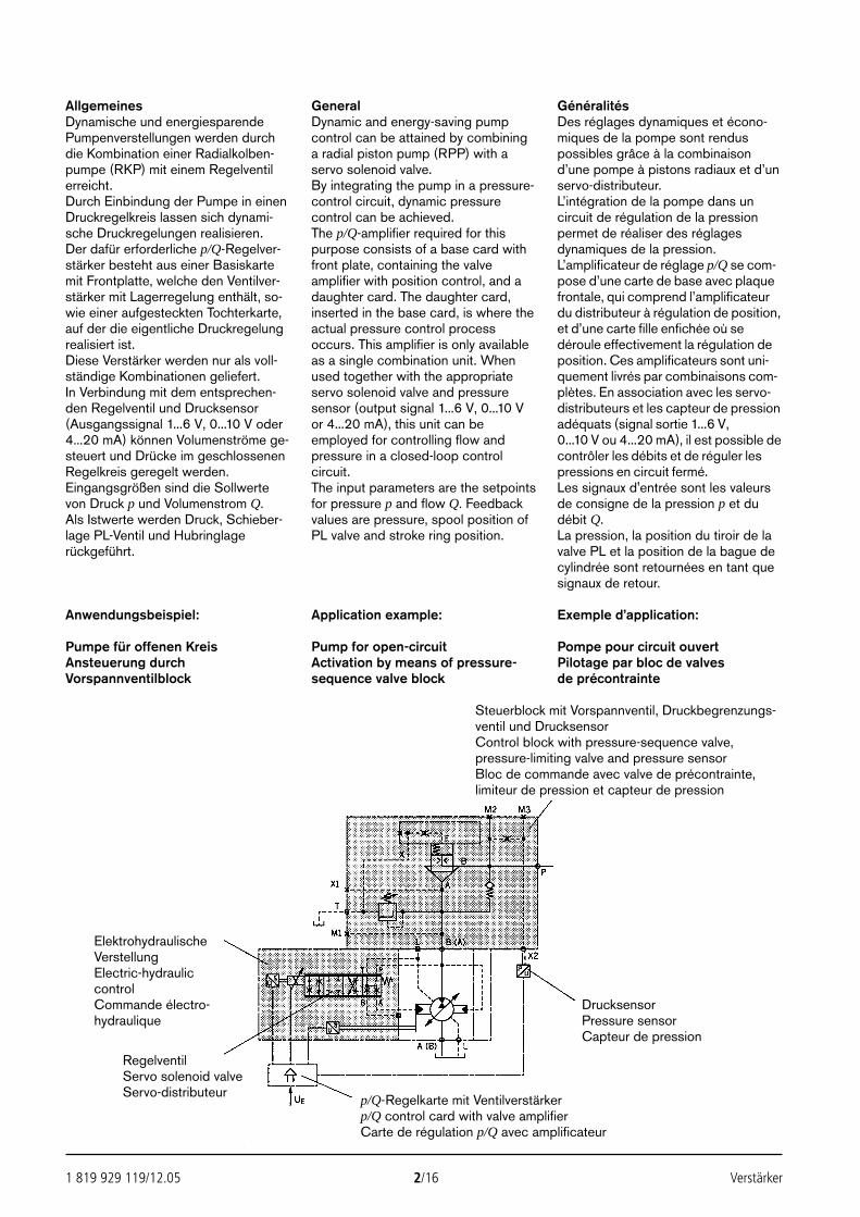
1 819 929 119/12.05 2/16 Verstärker
AllgemeinesDynamische und energiesparendePumpenverstellungen werden durchdie Kombination einer Radialkolben-pumpe (RKP) mit einem Regelventilerreicht.Durch Einbindung der Pumpe in einenDruckregelkreis lassen sich dynami-sche Druckregelungen realisieren.Der dafür erforderliche p/Q-Regelver-stärker besteht aus einer Basiskartemit Frontplatte, welche den Ventilver-stärker mit Lagerregelung enthält, so-wie einer aufgesteckten Tochterkarte,auf der die eigentliche Druckregelungrealisiert ist.Diese Verstärker werden nur als voll-ständige Kombinationen geliefert.In Verbindung mit dem entsprechen-den Regelventil und Drucksensor(Ausgangssignal 1...6 V, 0...10 V oder4...20 mA) können Volumenströme ge-steuert und Drücke im geschlossenenRegelkreis geregelt werden.Eingangsgrößen sind die Sollwertevon Druck p und Volumenstrom Q. Als Istwerte werden Druck, Schieber-lage PL-Ventil und Hubringlagerückgeführt.
GeneralDynamic and energy-saving pumpcontrol can be attained by combininga radial piston pump (RPP) with aservo solenoid valve.By integrating the pump in a pressure-control circuit, dynamic pressurecontrol can be achieved.The p/Q-amplifier required for thispurpose consists of a base card withfront plate, containing the valveamplifier with position control, and adaughter card. The daughter card,inserted in the base card, is where theactual pressure control processoccurs. This amplifier is only availableas a single combination unit. Whenused together with the appropriateservo solenoid valve and pressuresensor (output signal 1...6 V, 0...10 Vor 4...20 mA), this unit can beemployed for controlling flow andpressure in a closed-loop controlcircuit.The input parameters are the setpointsfor pressure p and flow Q. Feedbackvalues are pressure, spool position ofPL valve and stroke ring position.
GénéralitésDes réglages dynamiques et écono-miques de la pompe sont renduspossibles grâce à la combinaisond’une pompe à pistons radiaux et d’unservo-distributeur.L’intégration de la pompe dans uncircuit de régulation de la pressionpermet de réaliser des réglagesdynamiques de la pression.L’amplificateur de réglage p/Q se com-pose d’une carte de base avec plaquefrontale, qui comprend l’amplificateurdu distributeur à régulation de position,et d’une carte fille enfichée où sedéroule effectivement la régulation deposition. Ces amplificateurs sont uni-quement livrés par combinaisons com-plètes. En association avec les servo-distributeurs et les capteur de pressionadéquats (signal sortie 1...6 V,0...10 V ou 4...20 mA), il est possible decontrôler les débits et de réguler lespressions en circuit fermé.Les signaux d'entrée sont les valeursde consigne de la pression p et dudébit Q.La pression, la position du tiroir de lavalve PL et la position de la bague decylindrée sont retournées en tant quesignaux de retour.
Anwendungsbeispiel:
Pumpe für offenen KreisAnsteuerung durch Vorspannventilblock
Application example:
Pump for open-circuitActivation by means of pressure-sequence valve block
Exemple d’application:
Pompe pour circuit ouvertPilotage par bloc de valvesde précontrainte
Steuerblock mit Vorspannventil, Druckbegrenzungs-ventil und DrucksensorControl block with pressure-sequence valve,pressure-limiting valve and pressure sensorBloc de commande avec valve de précontrainte,limiteur de pression et capteur de pression
DrucksensorPressure sensorCapteur de pression
RegelventilServo solenoid valveServo-distributeur
ElektrohydraulischeVerstellungElectric-hydrauliccontrolCommande électro-hydraulique
p/Q-Regelkarte mit Ventilverstärkerp/Q control card with valve amplifierCarte de régulation p/Q avec amplificateur
2592_UBY013_126_001-016.qxd 30.11.2005 9:49 Uhr Seite 2
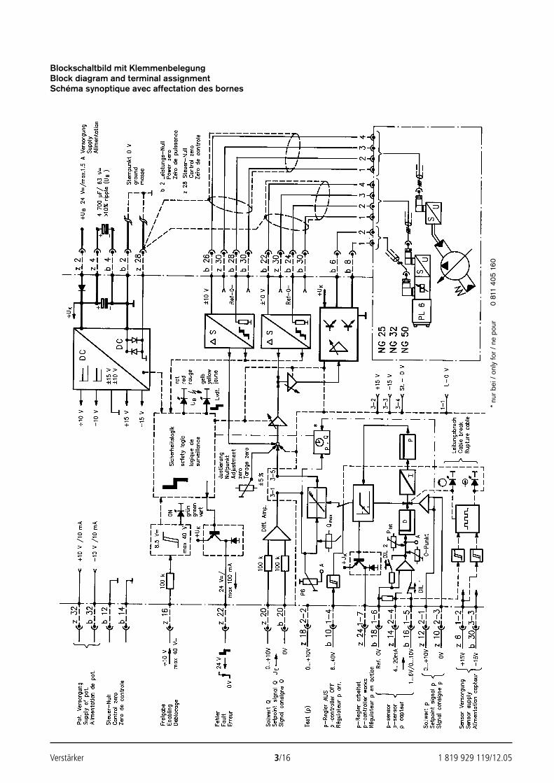
Verstärker 3/16 1 819 929 119/12.05
Blockschaltbild mit KlemmenbelegungBlock diagram and terminal assignmentSchéma synoptique avec affectation des bornes
* nu
r bei
/ o
nly
for /
ne
pour
0 81
1 40
5 16
0
2592_UBY013_126_001-016.qxd 30.11.2005 9:49 Uhr Seite 3
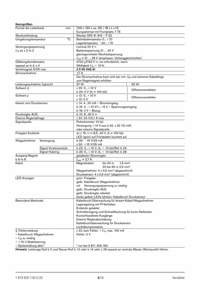
1 819 929 119/12.05 4/16 Verstärker
KenngrößenFormat der Leiterkarte mm (100 x 160 x ca. 35) / (B x L x H)
Europaformat mit Frontplatte 7 TESteckverbindung Stecker DIN 41 612 – F 32Umgebungstemperatur °C Betriebstemperatur 0...70
Lagertemperatur 20...70Versorgungsspannung nominal 24 V =UB an z 2–b 2 Batteriespannung 21 ... 40 V
gleichgerichtete WechselspannungUeff = 21 ... 28 V (einphasen, Vollweggleichrichter)
Glättungskondensator, 4700 µF/63 V =, nur erforderlich, wennseparat an b 4, z 4 Welligkeit UB 10 %Ventilmagnet A/VA max. 2,7/40 (NG 6)Stromaufnahme 1,7 A
Die Stromaufnahme kann sich bei min. UB und extremer Kabellängezum Regelmagnet erhöhen
Leistungsaufnahme (typisch) 37 W 55 WSollwert Q z 20: 0...10 V
b 20: 0 V (Ri = 100 kΩ)Differenzverstärker
Sollwert p z 12: 0...10 Vz 10: 0 V
Differenzverstärker
Istwert vom Drucksensor z 14: 4...20 mA – Stromeingangb 16: 0...10 V/1...6 V – Spannungseingangb 18: 0 V – Bezug
Druckregler AUS b 10: 6...40 V =Externe Reglerabfrage z 24: 24 V/0,1 A max.Signalquelle Potentiometer 10 kΩ
Versorgung 10 V aus b 32, z 32 (10 mA)oder externe Signalquelle
Freigabe Endstufe an z 16, U = 8,5...40 V, Ri = 100 kΩ,LED (grün) auf Frontplatte leuchtet auf
Wegaufnehmer Versorgung b 30: 15 V/25 mAz 30: 15 V/35 mA
Signal Vorsteuerstufe b 22: 0...10 V, RL 10 kΩ/Ref. b 24Signal Hubring b 26: 0...10 V, RL 10 kΩ/Ref. b 28
Ausgang Magnet getakteter Stromreglerb 6–b 8 Imax. = 2,7 AKabel Magnetkabel: bis 20 m 1,5 mm2
20 bis 60 m 2,5 mm2
Wegaufnehmer: 4 x 0,5 mm2 (abgeschirmt)Drucksensor: 4 x 0,5 mm2 (abgeschirmt)
LED-Anzeigen grün: Freigabegelb: Kabelbruch Wegaufnehmerrot: Versorgungsspannung zu niedriggelb: Druckregler AUSgelb: Druckregler arbeitetbeide gelben LEDs blinken: Kabelbruch Drucksensor
Besondere Merkmale Kabelbruch-Überwachung für Istwert-Kabel-WegaufnehmerLageregelung mit PI-VerhaltenEndstufe getaktetSchnellerregung und Schnelllöschung für kurze StellzeitenKurzschlussfeste AusgängeExterne ReglerabschaltungKabelbruchüberwachung für DrucksensorLeckölkompensation
∑ Fehlermeldung z 22; kein Fehler: UK; max. 100 mA– Kabelbruch Wegaufnehmer Fehler: 0 V– UB zu niedrig– 15 V-Stabilisierung– Spülschaltung aktiv* * nur bei 0 811 405 160Hinweis: Leistungs-Null b 2 und Steuer-Null b 12 oder b 14 oder z 28 separat an zentrale Masse (Sternpunkt) führen.
2592_UBY013_126_001-016.qxd 30.11.2005 9:49 Uhr Seite 4
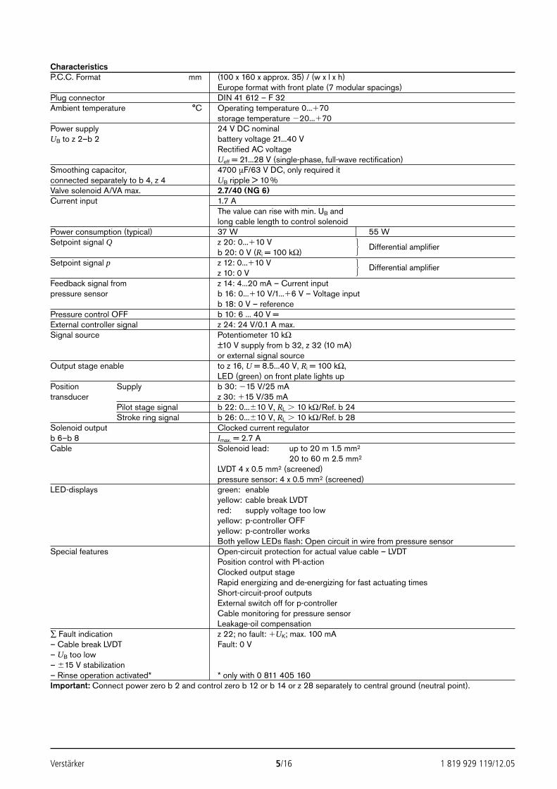
Verstärker 5/16 1 819 929 119/12.05
CharacteristicsP.C.C. Format mm (100 x 160 x approx. 35) / (w x l x h)
Europe format with front plate (7 modular spacings)Plug connector DIN 41 612 – F 32Ambient temperature °C Operating temperature 0...70
storage temperature 20...70Power supply 24 V DC nominalUB to z 2–b 2 battery voltage 21...40 V
Rectified AC voltageUeff = 21...28 V (single-phase, full-wave rectification)
Smoothing capacitor, 4700 µF/63 V DC, only required itconnected separately to b 4, z 4 UB ripple > 10 %Valve solenoid A/VA max. 2.7/40 (NG 6)Current input 1.7 A
The value can rise with min. UB andlong cable length to control solenoid
Power consumption (typical) 37 W 55 WSetpoint signal Q z 20: 0...10 V
b 20: 0 V (Ri = 100 kΩ)Differential amplifier
Setpoint signal p z 12: 0...10 Vz 10: 0 V
Differential amplifier
Feedback signal from z 14: 4...20 mA – Current inputpressure sensor b 16: 0...10 V/1...6 V – Voltage input
b 18: 0 V – referencePressure control OFF b 10: 6 ... 40 V =External controller signal z 24: 24 V/0.1 A max.Signal source Potentiometer 10 kΩ
±10 V supply from b 32, z 32 (10 mA)or external signal source
Output stage enable to z 16, U = 8.5...40 V, Ri = 100 kΩ,LED (green) on front plate lights up
Position Supply b 30: 15 V/25 mAtransducer z 30: 15 V/35 mA
Pilot stage signal b 22: 0...10 V, RL 10 kΩ/Ref. b 24Stroke ring signal b 26: 0...10 V, RL 10 kΩ/Ref. b 28
Solenoid output Clocked current regulatorb 6–b 8 Imax. = 2.7 ACable Solenoid lead: up to 20 m 1.5 mm2
20 to 60 m 2.5 mm2
LVDT 4 x 0.5 mm2 (screened)pressure sensor: 4 x 0.5 mm2 (screened)
LED-displays green: enableyellow: cable break LVDTred: supply voltage too lowyellow: p-controller OFFyellow: p-controller worksBoth yellow LEDs flash: Open circuit in wire from pressure sensor
Special features Open-circuit protection for actual value cable – LVDTPosition control with PI-actionClocked output stageRapid energizing and de-energizing for fast actuating timesShort-circuit-proof outputsExternal switch off for p-controllerCable monitoring for pressure sensorLeakage-oil compensation
∑ Fault indication z 22; no fault: UK; max. 100 mA– Cable break LVDT Fault: 0 V– UB too low– 15 V stabilization– Rinse operation activated* * only with 0 811 405 160Important: Connect power zero b 2 and control zero b 12 or b 14 or z 28 separately to central ground (neutral point).
2592_UBY013_126_001-016.qxd 30.11.2005 9:49 Uhr Seite 5
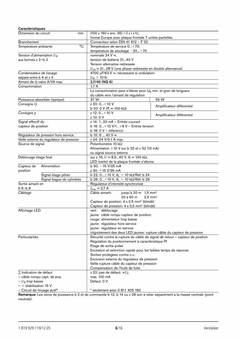
1 819 929 119/12.05 6/16 Verstärker
CaractéristiquesDimension du circuit mm (100 x 160 x env. 35) / (l x l x h),
format Europe avec plaque frontale 7 unités partiellesBranchement Connecteur selon DIN 41 612 – F 32Température ambiante °C Température de service 0...70;
température de stockage 20...70Tension d’alimentation UB nominale 24 V =,aux bornes z 2–b 2 tension de batterie 21...40 V
Tension alternative redresséeUeff = 21...28 V (une phase redressée en double alternance)
Condensateur de lissage 4700 µF/63 V =, nécessaire si ondulationséparé entre b 4 et z 4 UB 10 %Aimant de la valve A/VA max. 2,7/40 (NG 6)Consommation 1,7 A
La consommation peut s’élever pour UB min. et gran de longueurdu câble vers l’aimant de régulation
Puissance absorbée (typique) 37 W 55 WConsigne Q z 20: 0...10 V
b 20: 0 V (Ri = 100 kΩ)Amplificateur différentiel
Consigne p z 12: 0...10 Vz 10: 0 V
Amplificateur différentiel
Signal effectif du z 14: 1...20 mA – Entrée courantcapteur de position b 16: 0...10 V/1...6 V – Entrée tension
b 18: 0 V – référenceRégulateur de pression hors service b 10: 6 ... 40 V =Veille externe du régulateur de pression z 24: 24 V/0,1 A max.Source de signal Potentiomètre 10 kΩ
Alimentation 10 V sur b 32 et z 32 (10 mA)ou signal source externe
Déblocage étage final sur z 16, U = 8,5...40 V, Ri = 100 kΩ,LED (verte) de la plaque frontale s’allume
Capteur de Alimentation b 30: 15 V/25 mAposition z 30: 15 V/35 mA
Signal étage pilote b 22: 0...10 V, RL 10 kΩ/Réf. b 24Signal bague de cylindrée b 26: 0...10 V, RL 10 kΩ/Réf. b 28
Sortie aimant en Régulateur d’intensité synchroniséb 6–b 8 Imax. = 2,7 ACâblage Câble aimant: jusqu’à 20 m 1,5 mm2
20 à 60 m 2,5 mm2
Capteur de position: 4 x 0,5 mm2 (blindé)Capteur de pression: 4 x 0,5 mm2 (blindé)
Affichage LED vert: déblocagejaune: câble rompu capteur de positionrouge: alimentation trop bassejaune: régulateur hors servicejaune: régulateur en serviceclignotement des deux LED jaunes: rupture câble du capteur de pression
Particularités Sécurité contre la rupture du câble de signal de retour – capteur de positionRégulation du positionnement à caractéristique PIEtage de sortie pulséExcitation et extinction rapide pour les faibles temps de réponseSorties protégées contre c.c.Exclusion externe du régulateur de pressionVeille rupture câble du capteur de pressionCompensation de l’huile de fuite
∑ Indication de défaut z 22; pas de défaut: +UK
– câble rompu capt. de pos. max. 100 mA– UB trop basse Défaut: 0 V– stabilisation 15 V– Circuit de rinçage actif* * seulement avec 0 811 405 160Remarque: Les zéros de puissance b 2 et de commande b 12, b 14 ou z 28 son à relier séparément à la masse centrale (pointneutrale).
2592_UBY013_126_001-016.qxd 30.11.2005 9:49 Uhr Seite 6
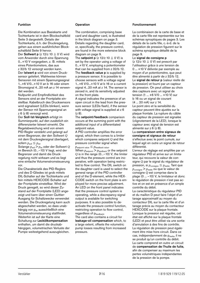
Verstärker 7/16 1 819 929 119/12.05
Funktion
Die Kombination aus Basiskarte undTochterkarte ist in dem BlockschaltbildSeite 3 dargestellt. Details derTochterkarte, d.h. der Druckregelung,gehen aus einem ausführlichen Block-schaltbild Seite 9 hervor.Der Sollwert p (z 12/z 10 0 V) wirdvom Anwender durch eine Spannung0...+10 V vorgegeben, z. B. mittelseines Potentiometers, das ausz 32/b 12 versorgt werden kann.Der Istwert p wird von einem Druck-sensor geliefert. Wahlweise könnenSensoren mit einem Spannungssignal1...+6 V/0...+10 V an b 16 oder einemStromsignal 4...20 mA an z 14 verwen-det werden.Nullpunkt und Empfindlichkeit desSensors sind an der Frontplatte ein-stellbar. Kabelbruch des Drucksensorswird signalisiert (LEDs blinken), wennder Sensor mit Spannungssignal anz 6 (z 8) versorgt wird.Der Soll-Ist-Vergleich erfolgt imSummierpunkt, auf den zusätzlich eindifferenzierter Istwert einwirkt. DieRegelabweichung wird von einemPID-Regler verstärkt und gelangt aufeinen Begrenzer, der den Sollwert Qmit dem Druckreglersignal überlagert,sofern psoll pist.Solange psoll > pist oder der Sollwert Qim Bereich (0...–10) V liegt, wird derBegrenzer und damit die Druck-regelung nicht wirksam und es liegteine einfache Volumenstromsteuerungvor.Die Charakteristik des PID-Reglersund des D-Gliedes ist grob mittelsDIL-Schalter auf der Tochterkarte undfein mittels HEXCODE-Schalter aufder Frontplatte einstellbar. Wird derDruck geregelt, so wird dieser Zu-stand auf der Frontplatte (LED) ange-zeigt und kann über einen Quittier-Ausgang für Schaltzwecke verwendetwerden. Die Druckregelung kann auchabgeschaltet werden, so dass unab-hängig von pist ausschließlich eineVolumenstromsteuerung stattfindet.Weiterhin ist auf der Karte eineSchaltung zur Leckölkompensationenthalten, um damit die druckab-hängigen, volumetrischen Verluste derPumpe weitestgehend auszugleichen.
Operation
The combination, comprising basecard and daughter card, is illustratedin the block diagram on page 3.Details regarding the daughter card,or, specifically, the pressure control,are found in the more extensive blockdiagram on page 9.The setpoint p (z 12/z 10 0 V) isset by the operator using a voltage of0...+10 V, employing a potentiometerthat can be supplied from z 32/b 12.The feedback value p is supplied bya pressure sensor. It is possible tochoose sensors with a voltage signal1...+6 V/0...+10 V at b 16 or a currentsignal 4...20 mA at z 14. The sensor iszeroed in, and its sensitivity adjustedon the front plate.A signal indicates the presence of anopen circuit in the lead from the pres-sure sensor (LEDs flash), if the sensorwith voltage signal is supplied at z 6(z 8).The setpoint/feedback comparisonoccurs at the summing point with theadditional input of a differentiatedsetpoint value.A PID controller amplifies the errorsignal, which then comes to a limiterwhich compares setpoint Q and thepressure controller signal whenpsetpoint value pfeedback value.When psetpoint > pfeedback or the setpointQ is in the range (0...–10) V, the limiterand thus the pressure control are ino-perative, with operation being restric-ted to flow control. The DIL switch onthe daughter card is used to select thegeneral range of the PID controllerand of the D-element, while the HEX-CODE switch on the front plate is em-ployed for more precise adjustment. An LED on the front panel indicatesthat the pressure control system isoperating, while a discrepancy signaloutput is available for switchingpurposes. It is also possible to de-activate the pressure control function,restricting operation to flow control,regardless of pfeedback.The card also contains a circuit forleakage-oil compensation which, toa large extent, offsets the volumetricpump losses resulting from increasedpressure.
Fonctionnement
La combinaison de la carte de base etde la carte fille est représentée sur lesschémas synoptiques de pages 3. Lesdétails de la carte fille, c.-à-d. de larégulation de pression figurent sur leschéma synoptique détaillé de la page 9.Le signal de consigne p(z 12/z 10 0 V) est prescrit par l’utilisateur grâce à une tension de0 ... +10 V délivrée par exemple aumoyen d’un potentiomètre, que peutêtre alimenté à partir de z 32/b 12.Le signal de retour p (valeur réelle dela pression) et fourni par un capteurde pression. On peut utiliser au choixdes capteurs avec un signal detension (1 ... +6 V/0 ... +10 V) sur b 16 ou un signal de courant (4 ... 20 mA) sur z 14.Le point zéro et la sensibilité ducapteur peuvent être ajustés sur laplaque frontale. La rupture du câbledu capteur de pression est signalée(clignotement de la LED), lorsque lecapteur avec signal de tension estalimenté sur z 6 (z 8).La comparaison entre signaux deconsigne et signaux de retours’effectue avec le point cumulé, surlequel agit en outre un signal de retourdifférentié.L’erreur de réglage est amplifée par unrégulateur PID et arrive sur un limita-teur, qui recouvre la valeur de con-signe Q par le signal du régulateur depression, si pconsigne préelle. Tant quepconsigne > préelle ou que le valeur deconsigne Q est comprise dans laplage (0 ... –10) V, le limitateur et doncle régulation de pression n’est pas ac-tive et on est en présence d’un simplecontrôle du débit.La caractéristique du régulateur PIDet du maillon D peut faire l’objet d’untarage approximatif au moyen ducontacteur DIL sur la carte fille et d’untarage précis au moyen du contacteurHEXCODE sur la plaque frontale.Lorsque la pression est régulée, cetétat est affiché sur la plaque frontale(LED) et peut être utilisé via une sortied’annulation à des fins de contrôle.La régulation de pression peut égale-ment être mise hors circuit. Dans cecas, indépendamment de préelle, il nese produit qu’un contrôle du débit.La carte comprend en outre un circuitde compensation de l’huile de fuite,afin de compenser au maximum lespertes volumétriques indépendantesde la pression de la pompe.
2592_UBY013_126_001-016.qxd 30.11.2005 9:49 Uhr Seite 7
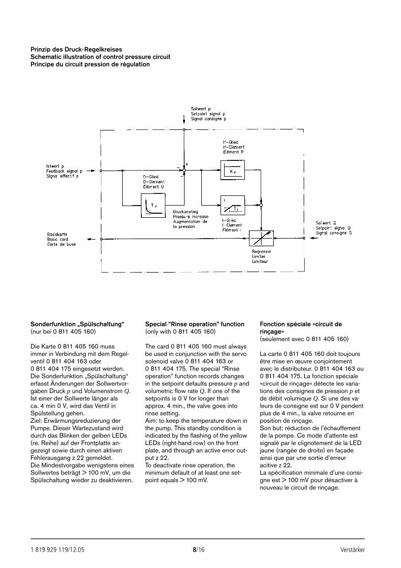
1 819 929 119/12.05 8/16 Verstärker
Prinzip des Druck-RegelkreisesSchematic illustration of control pressure circuitPrincipe du circuit pression de régulation
Sonderfunktion „Spülschaltung“(nur bei 0 811 405 160)
Die Karte 0 811 405 160 mussimmer in Verbindung mit dem Regel-ventil 0 811 404 163 oder 0 811 404 175 eingesetzt werden.Die Sonderfunktion „Spülschaltung“erfasst Änderungen der Sollwertvor-gaben Druck p und Volumenstrom Q.Ist einer der Sollwerte länger als ca. 4 min 0 V, wird das Ventil inSpülstellung gehen. Ziel: Erwärmungsreduzierung derPumpe. Dieser Wartezustand wirddurch das Blinken der gelben LEDs(re. Reihe) auf der Frontplatte an-gezeigt sowie durch einen aktivenFehlerausgang z 22 gemeldet.Die Mindestvorgabe wenigstens einesSollwertes beträgt > 100 mV, um dieSpülschaltung wieder zu deaktivieren.
Special “Rinse operation” function(only with 0 811 405 160)
The card 0 811 405 160 must alwaysbe used in conjunction with the servosolenoid valve 0 811 404 163 or 0 811 404 175. The special “Rinseoperation” function records changesin the setpoint defaults pressure p andvolumetric flow rate Q. If one of thesetpoints is 0 V for longer thanapprox. 4 min., the valve goes intorinse setting. Aim: to keep the temperature down inthe pump. This standby condition isindicated by the flashing of the yellowLEDs (right-hand row) on the frontplate, and through an active error out-put z 22.To deactivate rinse operation, theminimum default of at least one set-point equals > 100 mV.
Fonction spéciale «circuit derinçage»(seulement avec 0 811 405 160)
La carte 0 811 405 160 doit toujoursêtre mise en œuvre conjointementavec le distributeur. 0 811 404 163 ou 0 811 404 175. La fonction spéciale«circuit de rinçage» détecte les varia-tions des consignes de pression p etde débit volumique Q. Si une des va-leurs de consigne est sur 0 V pendentplus de 4 min., la valve retourne enposition de rinçage.Son but: réduction de l’échauffementde la pompe. Ce mode d’attente estsignalé par le clignotement de la LEDjaune (rangée de droite) en façadeainsi que par une sortie d’erreuracitive z 22.La spécification minimale d’une consi-gne est > 100 mV pour désactiver ànouveau le circuit de rinçage.
2592_UBY013_126_001-016.qxd 30.11.2005 9:49 Uhr Seite 8
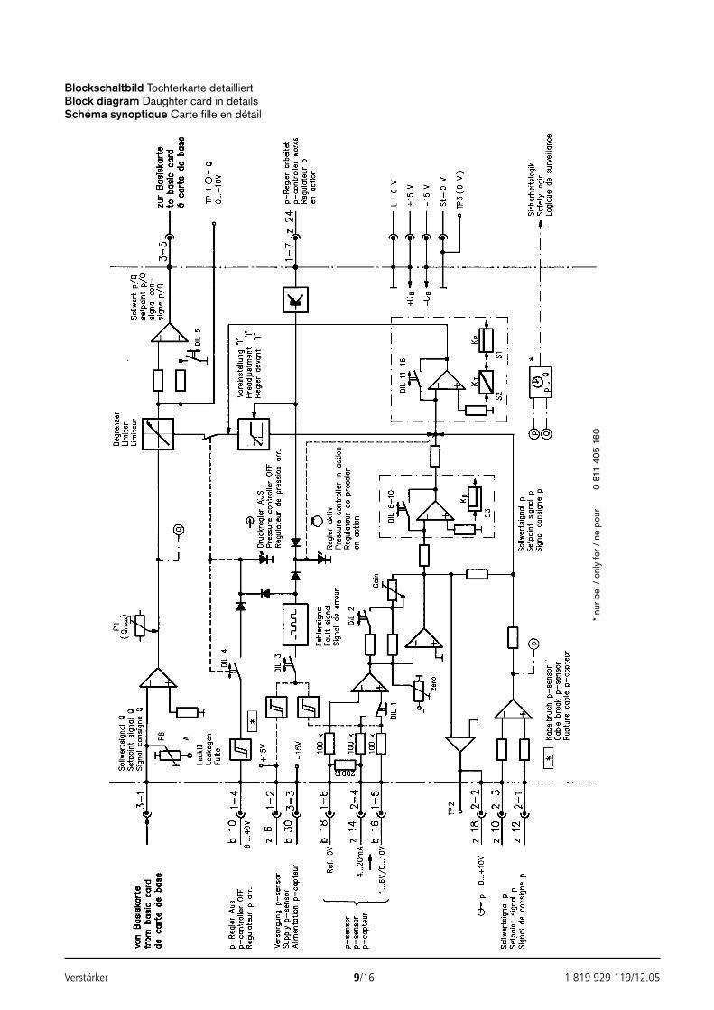
Verstärker 9/16 1 819 929 119/12.05
Blockschaltbild Tochterkarte detailliertBlock diagram Daughter card in detailsSchéma synoptique Carte fille en détail
* nu
r bei
/ o
nly
for /
ne
pour
0 81
1 40
5 16
0
2592_UBY013_126_001-016.qxd 30.11.2005 9:49 Uhr Seite 9
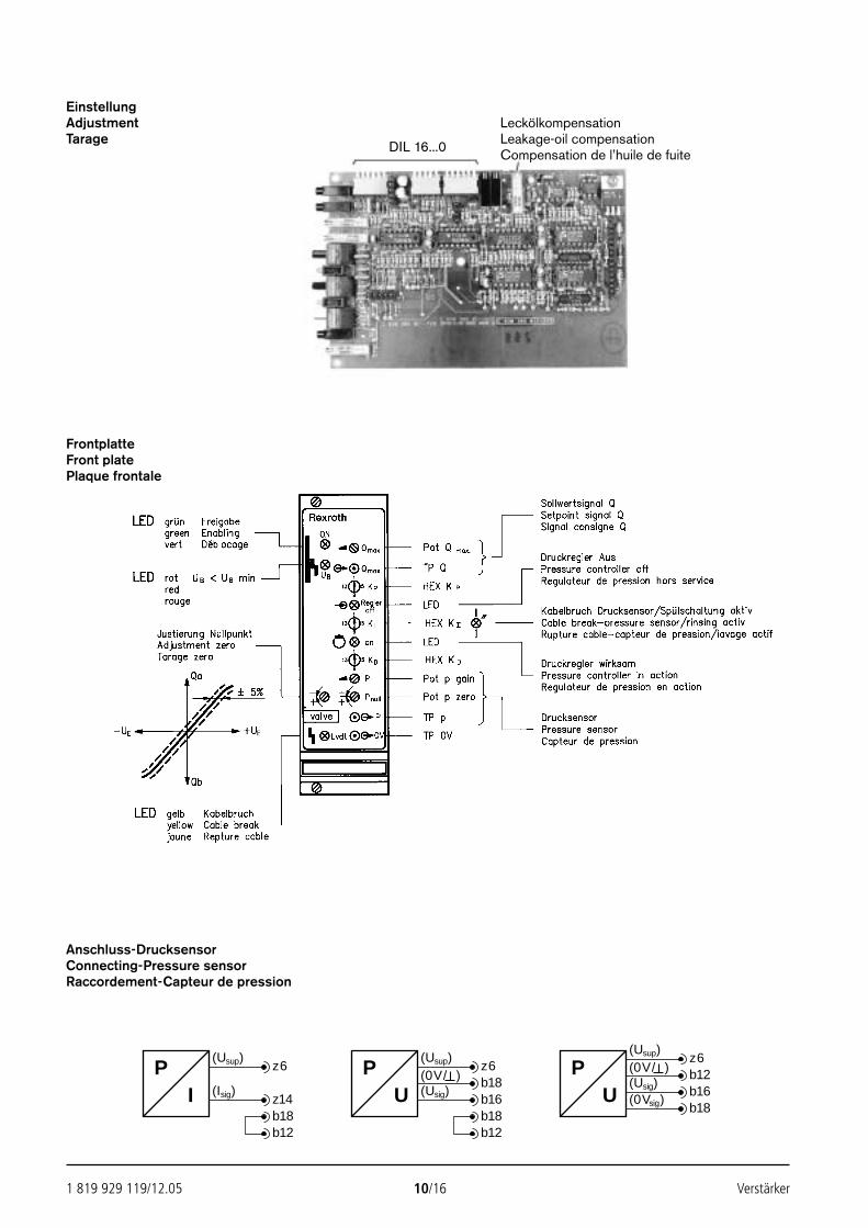
1 819 929 119/12.05 10/16 Verstärker
EinstellungAdjustmentTarage
FrontplatteFront platePlaque frontale
DIL 16...0
LeckölkompensationLeakage-oil compensationCompensation de l’huile de fuite
(Usup)PI
z6
(Isig) z14
(Usup)PU
z6(0V/ ) b18(Usig) b16
b18b12
b18b12
(Usup)
PU
z6(0V/ ) b12(Usig) b16(0Vsig)
b18
Anschluss-DrucksensorConnecting-Pressure sensorRaccordement-Capteur de pression
2592_UBY013_126_001-016.qxd 30.11.2005 9:49 Uhr Seite 10
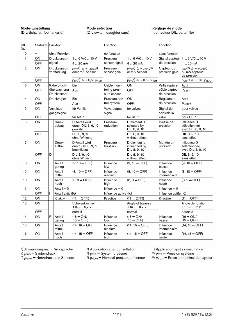
Verstärker 11/16 1 819 929 119/12.05
Mode-Einstellung(DIL-Schalter, Tochterkarte)
Mode selection(DIL switch, daughter card)
Réglage de mode(contacteur DIL, carte fille)
1) Anwendung nach Rücksprache2) pSYS = Systemdruck3) pNOM = Nenndruck des Sensors
1) Application after consultation2) pSYS = System pressure3) pNOM = Nominal pressure of sensor
1) Application après consultation2) pSYS = Pression système3) pNOM = Pression nominal du capteur
DIL- Status2) Funktion Function FonctionNr.
10 – ohne Funktion no function sans fonction11 ON Drucksensor- 1 ... 6 V/0 ... 10 V Pressure 1 ... 6 V/0 ... 10 V Signal capteur 1 ... 6 V/0 ... 10 V
OFF signal 4 ... 20 mA sensor signal 4 ... 20 mA de pression 4 ... 20 mA12 ON Drucksensor- pSYS
2) ~ pNOM3) Pressure pSYS
2) ~ pNOM3) Capteur de pSYS
2) ~ pNOM3)
verstärkung oder mA-Sensor sensor gain or mA-Sensor pression gain ou mA capteurde pression
OFF pSYS1) ~ 0,5 · pNOM pSYS
1) ~ 0.5 · pNOM pSYS1) ~ 0,5 · pNOM
13 ON Kabelbruch- Ein Cable moni- ON Veille rupture ActifOFF überwachung Aus toring pres- OFF câble capteur Passif
Drucksensor sure sensor de pression14 ON Druckregler Ein Pressure con- ON Régulateur Actif
OFF Aus trol system OFF de pression Passiv15 ON Ventilaus- für Ventile Valve output for valves Signal de pour valves
gangssignal signal sortiede la OFF für RKP for RPP valve pour PPR
16 ON Druck- D-Anteil wird Pressure D-element is Baisse de Influence Dabbau durch DIL 8, 9, 10 reduction selected by pression sélectionnée
gewählt DIL 8, 9, 10 avec DIL 8, 9, 10OFF DIL 8, 9, 10 DIL 8, 9, 10 DIL 8, 9, 10
ohne Wirkung without effect sans effet17 ON Druck- D-Anteil wird Pressure D-element is Montée en Influence D
aufbau durch DIL 8, 9, 10 build-up influenced by pression sélectionnéebeeinflusst DIL 8, 9, 10 avec DIL 8, 9, 10
OFF D DIL 8, 9, 10 DIL 8, 9, 10 DIL 8, 9, 10ohne Wirkung without effect sans effet
18 ON Anteil (9, 10 = OFF) Influence (9, 10 = OFF) Influence (9, 10 = OFF)gering low basse
19 ON Anteil (8, 10 = OFF) Influence (8, 10 = OFF) Influence (8, 10 = OFF)mittel medium intermédiaire
10 ON Anteil (8, 9 = OFF) Influence (8, 9 = OFF) Influence (8, 9 = OFF)hoch high haute
11 ON Anteil = 0 Influence = 0 Influence = 0OFF I Anteil aktiv (KI) Influence active (KI) Influence actife (KI)
12 ON KI aktiv (11 = OFF!) KI active (11 = OFF!) KI active (11 = OFF!)13 ON Schwenkwinkel Angle of traverse Angle de rotation
+10 ... –0,7 V +10 ... –0.7 V +10 ... –0,7 VOFF normal normal normale
14 ON P Anteil (16 = ON/ Influence (16 = ON/ Influence (16 = ON/gering (15 = OFF) low (15 = OFF) basse (15 = OFF)
15 ON Anteil (14, 16 = OFF) Influence (14, 16 = OFF) Influence (14, 16 = OFF)mittel medium intermédiaire
16 ON Anteil (14, 15 = OFF) Influence (14, 15 = OFF) Influence (14, 15 = OFF)hoch high haute
2592_UBY013_126_001-016.qxd 30.11.2005 9:49 Uhr Seite 11
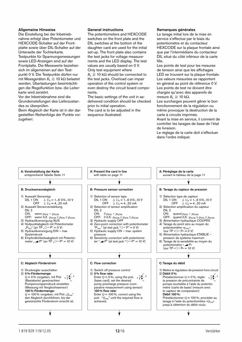
1 819 929 119/12.05 12/16 Verstärker
Allgemeine HinweiseDie Einstellung bei der Inbetrieb-nahme erfolgt über Potentiometer undHEXCODE-Schalter auf der Front-platte sowie über DIL-Schalter auf derUnterseite der Tochterkarte. Testpunkte für Spannungsmessungensowie LED-Anzeigen sind auf derFrontplatte. Die Messwerte beziehensich im allgemeinen auf den Test-punkt 0 V. Die Testpunkte dürfen nurmit Messgeräten RL 10 kΩ belastetwerden. Überlastungen beeinträchti-gen die Regelfunktion bzw. die Leiter-karte wird zerstört.Vor der Inbetriebnahme sind dieGrundeinstellungen des Lieferzustan-des zu überprüfen.Beim Abgleich der Karte ist in der dar-gestellten Reihenfolge der Punkte vor-zugehen:
General instructionsThe potentiometers and HEXCODEswitches on the front plate and theDIL switches at the bottom of thedaughter card are used for the initialset-up. The front plate also containsthe test jacks for voltage measure-ments and the LED display. The testvalues are usually based on 0 V.Only test equipment where RL 10 kΩ should be connected tothe test jacks. Overload can impairoperation of the control system oreven destroy the circuit board compo-nents.The basic settings of the unit in as-delivered condition should be checkedprior to initial operation. The card is to be adjusted in thesequence illustrated:
Remarques généralesLe tarage initial lors de la mise enservice s’effectue par le biais dupotentiomètre et du contacteurHEXCODE sur la plaque frontale ainsique par l’intermédiaire du contacteurDIL situé du côté inférieur de la cartefille.Les points de test pour les mesuresde tension ainsi que les affichagesLED se trouvent sur la plaque frontale.Les valeurs mesurées se rapportenten général au point de référence 0 V.Les points de test ne doivent êtrechargés qu’avec des appareils demesure RL 10 kΩ.Les surcharges peuvent gêner le bonfonctionnement de la régulation oumême provoquer la destruction de lacarte à circuits imprimés.Avant la mise en service, il convient decontrôler les tarages de base de l’étatde livraison.Le réglage de la carte doit s’effectuerdans l’ordre indiqué:
A: Voreinstellung der Karteentsprechend Tabelle Seite 11
A: Present the card in linewith table on page 11
A: Péréglage de la cartesuivant le tableau de la page 11
B: Drucksensorabgleich
1) Auswahl SensortypDIL 1 ON UA = 1...6 V/0...10 V
OFF UA = 4...20 mA2) Auswahl Sensorverstärkung
DIL 2ON: wenn pSYS ~ pNOMOFF: wenn 0,5 · pNOM ≤ pSYS ≤ pNOM
3) Hydraulikversorgung AUS4) Nullpunktabgleich mit Potentiometer
„PNull“ (an TP „ P“ = 0 V)5) Hydraulikversorgung EIN – max.
Systemdruck6) Empfindlichkeitsabgleich mit Potentio-
meter „ P“ (an TP „ P“ = 10 V)
C: Abgleich Förderstrom
1) Druckregler ausschalten2) 0 %-Fördermenge:
Q = 0 % vorgeben, mit Poti (Basiskarte) gewünschtenPumpenvorspanndruck einstellen(Messung mit Vergleichssensor)100 %-Fördermenge:Q = 100 % vorgeben, mit Poti „Qmax“den Abgleich durchführen, bis dergewünschte Förderstrom erreicht ist.
C: Flow correction
1) Switch off pressure control2) 0 % flow rate:
Enter Q = 0 %; using the poti.(base card), set the desiredpump precharge pressure (com-parative measurement using sensor)100 % flow rate:Enter Q = 100 %, correct using the poti. “Qmax” until the required flow isachieved.
C: Tarage du débit
1) Mettre le régulateur de pression hors circuit2) Débit 0 %:
Présélectionner Q = 0 %, réglerla pression de précontrainte depompe souhaitée à l’aide du potentio-mètre (carte de base) (mesure avecle capteur de comparaison)Débit 100 %:Présélectionner Q = 100 %, procéder autarage à l’aide du potentiomètre «Qmax»jusqu’à obtention du débit voulu.
B: Pressure sensor correction
1) Selection of sensor typeDIL 1 ON UA = 1...6 V/0...10 V
OFF UA = 4...20 mA2) Selection of sensor amplification
DIL 2ON: if pSYS ~ pNOMOFF: if 0.5 · pNOM ≤ pSYS ≤ pNOM
3) Hydraulic supply OFF4) Zero-point correction with potentiometer
“Pzero” (at test jack “ P” = 0 V)5) Hydraulic supply ON – max. system
pressure6) Sensitivity correction with potentiome-
ter “ P” (at test jack “ P” = 10 V)
B: Tarage du capteur de pression
1) Sélection type de capteurDIL 1 ON UA = 1...6 V/0...10 V
OFF UA = 4...20 mA2) Sélection amplification du capteur
DIL 2ON: quand pSYS ~ pNOMOFF: quand 0,5 · pNOM ≤ pSYS ≥ pNOM
3) Alimentation hydraulique COUPEE4) Tarage du point zéro au moyen du
potentiomètre «pzéro» (sur TP « P» = 0 V)
5) Alimentation hydraulique ETABLIE – pression de système maximum
6) Tarage de la sensibilité au moyen dupotentiomètre « P» (sur TP « P» = 10 V)
2592_UBY013_126_001-016.qxd 30.11.2005 9:49 Uhr Seite 12
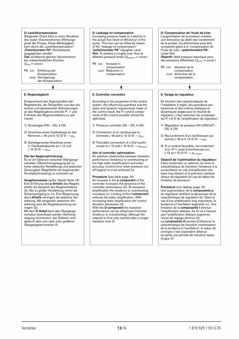
Verstärker 13/16 1 819 929 119/12.05
D: LeckölkompensationSteigender Druck führt zu einer Abnahmedes realen Volumenstromes (Wirkungs-grad) der Pumpe. Diese Abhängigkeit kann durch die „Leckölkompensation“„Potentiometer P6“ (Tochterkarte)ausgeglichen werden.Ziel: annähernd gleicher Volumenstrombei unterschiedlichen Drücken(Qsoll = const.)
P6 cw: Erhöhung derKompensation
ccw: Verringerungder Kompensation
D: Leakage-oil compensationIncreasing pressure leads to a decline inthe actual flow (level of efficiency) of the pump. This loss can be offset by meansof the “leakage-oil compensation”“potentiometer P6” (daughter card).Aim: To achieve a roughly even flow atdifferent pressure levels (Qsetpoint = const.)
P6 cw: Increase incompensation
ccw: Reduction incompensation
D: Compensation de l’huile de fuiteL’augmentation de la pression entraîneune diminution du débit réel (rendement)de la pompe. Ce phénomène peut êtrecompensé grâce à la «compensation del’huile de fuite» «potentiomètre P6»(carte fille).Objectif: débit presque indentique pourdes pressions différentes (Qcons. = const.)
P6 cw: élévation de lacompensation
ccw: diminution de lacompensation
E: Reglerabgleich
Entsprechend den Eigenschaften derRegelstrecke, der Störgrößen und den sta-tischen und dynamischen Anforderungen an das Regelergebnis sind die P-, I- und D-Anteile des Regelverstärkers zu opti-mieren.
1) Druckregler EIN – DIL 4 ON
2) Anschluss eines Oszilloskops an denKlemmen z 18 und b 12 (0 V) pist
3) Günstigerweise Anschluss eines2. Oszilloskopkanals an z 12 und z 10 (0 V) psoll
Ziel der Regleroptimierung:Es ist ein Optimum zwischen Übergangs-verhalten (Überschwingneigung bei zuhoher statischer Verstärkung) und statischerGenauigkeit (Regelfehler bei beginnenderDruckabschneidung) zu erreichen (a).
Vorgehensweise (siehe Tabelle Seite 14)Eine Erhöhung des p-Anteils des Reglers erhöht die Dynamik des Regelverhaltens(b). Bei zu großer Verstärkung nimmt dieSchwingneigung zu (c). Eine Begrenzungdes I-Anteils verringert die statische Ver-stärkung. Mit steigender statischer Ver-stärkung wird die Regelabweichung ver-ringert (d).Mit dem D-Anteil kann das Übergangs-verhalten beeinflusst werden (Schwing-neigung minimieren), der Sollwert wirddadurch aber erst nach einer größerenÜbergangszeit erreicht (f).
E: Controller correction
According to the properties of the controlsystem, the influencing quantities and thestatic and dynamic requirements made ofthe control result, the P, I and D compo-nents of the control amplifier should beoptimized.
1) Pressure controller ON – DIL 4 ON
2) Connection of an oscilloscope to terminals z 18 and b 12 (0 V) pact
3) Favorable connection of a 2nd oscillo-scope to z 12 and z 10 (0 V) psetpoint
Aim of controller optimization:An optimum relationship between transitionperformance (tendency to overshooting attoo high static amplification) and staticaccuracy (control error when pressure cut-off begins) is to be achieved (a).
Procedure (see table page 14)An increase in the p component of the controller increases the dynamics of thecontroller performance (b). At excessiveamplification the tendency to overshootingincreases (c). Limiting of the I componentreduces the static amplification. Withincreasing static amplification the controldeviation decreases (d).With the D component the transitionperformance can be influenced (minimizetendency to overshooting), although thesetpoint is thus only reached after a longertransition time (f).
E: Tarage du régulateur
En fonction des caractéristiques del’installation à régler, des grandeurs per-tubatrices et des critères statiques etdynamiques exigés pour le résultat derégulation, il faut optimiser les composan-tes P, I et D de l’amplificateur de régulation.
1) Régulateur de pression EN CIRCUIT –DIL 4 ON
2) Raccordement d’un oscilloscope aux bornes z 18 et b 12 (0 V) peff
3) A un endroit favorable, raccordement d’un 2ème canal d’oscilloscope sur z 12 et z 10 (0 V) pconsigne
Objectif de l’optimisation du régulateur:Il faut rechercher un optimum (a) entre lacaractéristique de transition (tendance à lasuroscillation en cas d’amplification sta-tique trop élevée) et la précision statique (erreur de régulation en cas de début delimitation de pression).
Procédure (voir tableau page 14)Une augmentation de la composante pdu régulateur améliore la dynamique de lacaractéristique de régulation (b). Dans le cas d’une amplification trop importante, latendance à l’oscillation augmente (c). Unelimitation de la composante I diminuel’amplification statique. Au fur et à mesureque l’amplification statique augmente, l’écart de réglage diminue (d).La composante D permet d’influencer lacaractéristique de transition (minimisationde la tendance à l’oscillation), la valeur deconsigne n’est cependant obtenue qu’après une période de transition assezlongue (f).
2592_UBY013_126_001-016.qxd 30.11.2005 9:49 Uhr Seite 13
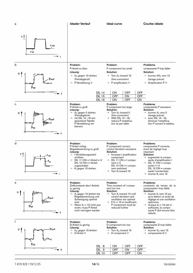
1 819 929 119/12.05 14/16 Verstärker
Idealer Verlauf Ideal curve Courbe idéale
Problem:P-Anteil zu kleinLösung: KP gegen 13 drehen
(Feinabgleich) P-Verstärkung >
Problem:P component too smallSolution: Turn KP toward 13
(fine-correction) P amplification >
Problème:composante P trop faibleSolution: tourner KKP vers 13
(tarage précis) Amplification P >
Problem:P-Anteil zu großLösung: KP gegen 0 drehen
(Feinabgleich) mit DIL 14 –16 ent-
sprechend TabelleP-Verstärkung ver-kleinern
Problem:P component too largeSolution: Turn KP toward 0
(fine-correction) With DIL 14 –16,
reduce P amplifica-tion as per table
Problème:composante P excessiveSolution: tourner KP vers 0
(tarage précis) avec DIL 14 –16,
diminuer l’amplifica-tion P suivant le tableau
Problem:P-Anteil richtig,Regelabweichung zu großLösung: I-Verstärkungsanteil
erhöhen DIL 11 ON = I-Anteil = 0
DIL 12 ON = I-Anteilzugeschaltet
KI gegen 13 drehen
Problem:P component correct,control deviation excessiveSolution: Increase I amplification
component DIL 11 ON = I compo-
nent = 0DIL 12 ON = I compo-nent switched
Turn KI toward 13
Problème:composante P correcte,écart de réglage tropimportantSolution: augmenter la compo-
sante d’amplification I DIL 11 ON = compo-
sante I = 0DIL 12 ON = compo-sante I enclenchés
tourner KI vers 13
Problem:Zeitkonstante des I-Anteilszu geringLösung: KI gegen 13 drehen bis
Regelabweichung undSchwingung optimalsind
Wenn KI = 13 nicht aus-reicht, muss P-Anteilnoch verringert werden
Problem:Time constant of I compo-nent too lowSolution: Turn KI toward 13 until
control deviation andoscillation are optimal
If KI = 13 is insufficient,P component must bereduced further
Problème:constante de temps de lacomposante I trop faibleSolution: tourner KI vers 13 jus-
qu’à obtenir un écart deréglage et une oscillationoptimums
lorsque KI = 13 est in-suffisante, la compo-sante P doit encore êtreréduite
Problem:D-Anteil zu geringLösung: KD gegen 13 drehen D-Anteil >
Problem:D component too lowSolution: Turn KD toward 13 D component >
Problème:composante D trop faibleSolution: tourner KD vers 13 composante D >
a
b
c
d
e
f
DIL 14 ON OFF OFFDIL 15 OFF ON OFFDIL 16 ON OFF ON
DIL 8 ON OFF OFFDIL 9 OFF ON OFFDIL 10 OFF OFF ON
2592_UBY013_126_001-016.qxd 30.11.2005 9:49 Uhr Seite 14
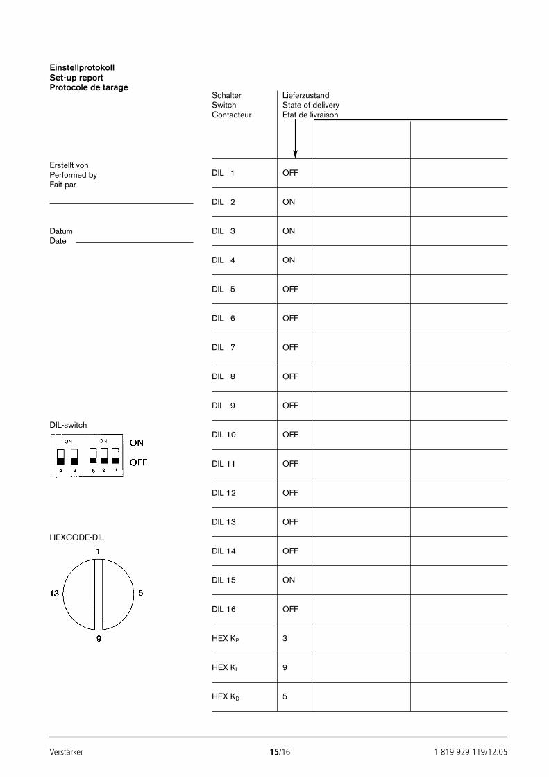
Verstärker 15/16 1 819 929 119/12.05
EinstellprotokollSet-up reportProtocole de tarage
Schalter LieferzustandSwitch State of deliveryContacteur Etat de livraison
Erstellt vonPerformed by DIL 1 OFFFait par
DIL 2 ON
Datum DIL 3 ONDate
DIL 4 ON
DIL 5 OFF
DIL 6 OFF
DIL 7 OFF
DIL 8 OFF
DIL 9 OFF
DIL-switchDIL 10 OFF
DIL 11 OFF
DIL 12 OFF
DIL 13 OFF
HEXCODE-DIL
DIL 14 OFF
DIL 15 ON
DIL 16 OFF
HEX KP 3
HEX KI 9
HEX KD 5
2592_UBY013_126_001-016.qxd 30.11.2005 9:49 Uhr Seite 15

Bosch Rexroth AGHydraulics
D-97813 Lohr am MainZum Eisengießer 1 D-97816 Lohr am MainTelefon 0 93 52/18-0Telefax 0 93 52/18-23 58 Telex 6 89 418-0eMail [email protected] www.boschrexroth.de
1 819 929 119/12.05 16/16 Verstärker
© Alle Rechte bei Bosch Rexroth AG, auch für den Fall von Schutzrechtsanmeldungen.Jede Verfügungsbefugnis, wie Kopier- und Weitergaberecht, bei uns.Die angegebenen Daten dienen allein der Produktbeschreibung. Eine Aussage übereine bestimmte Beschaffenheit oder eine Eignung für einen bestimmten Einsatzzweckkann aus unseren Angaben nicht abgeleitet werden. Die Angaben entbinden denVerwender nicht von eigenen Beurteilungen und Prüfungen. Es ist zu beachten, dassunsere Produkte einem natürlichen Verschleiß- und Alterungsprozess unterliegen.
2592_UBY013_126_001-016.qxd 30.11.2005 9:49 Uhr Seite 16
Industrial Electric Drives Linear Motion and Service MobileHydraulics and Controls Assembly Technologies Pneumatics Automation Hydraulics
1 819 929 066/06.02UBY 013/3
p/Q-Regelverstärkerp/Q-AmplifierAmplificateur p/Q
BedienungsanleitungInstruction manuelManuel d’utilisation
© 2002by Bosch Rexroth AG, Industrial Hydraulics, D-97813 Lohr am Main
Alle Rechte vorbehalten. Kein Teil des Werkes darf in irgendeiner Form ohne vorherige schriftliche Zustimmung von Bosch Rexroth AG,Industrial Hydraulics reproduziert oder unter Verwendung elektronischer Systeme gespeichert, verarbeitet, vervielfältigt oder verbreitet werden.Zuwiderhandlungen verpflichten zu Schadensersatz.
Dieses Werk wurde mit größter Sorgfalt erstellt und alle Angaben auf ihre Richtigkeit hin überprüft. Aus Gründen der ständigen Produkt-Weiterentwicklung müssen Änderungen vorbehalten bleiben. Für etwaige fehlerhafte oder unvollständige Angaben kann keine Haftung über-nommen werden.
Verstärker 1/16 1 819 929 066/06.02
AlphanumerikAlphanumeric Nr.Alphanumérique [kg] No.PQT – RKP Für Radialkolbenpumpen, inkl. Zeitabschaltung 0,25 0 811 405 110PQT – RKP For radial piston pumps, incl. time-stand by mode 0 811 405 125
Pour pompes à pistons radiaux, incl. time stand by mode
Druck-Regelung,Volumenstrom-Steuerunginkl. Ventilverstärker
Closed loop pressure control,Open loop flow controlincl. Valve amplifier
Régulation de pression,Contrôle de débitAmplificateur de valve incl.
23531_2978_U1_U4 13.06.2002 7:14 Uhr Seite 1
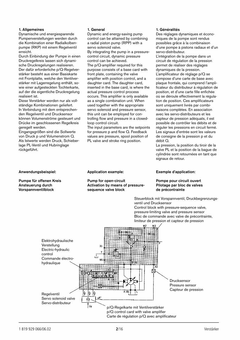
1 819 929 066/06.02 2/16 Verstärker
1. AllgemeinesDynamische und energiesparendePumpenverstellungen werden durchdie Kombination einer Radialkolben-pumpe (RKP) mit einem Regelventilerreicht.Durch Einbindung der Pumpe in einenDruckregelkreis lassen sich dynami-sche Druckregelungen realisieren.Der dafür erforderliche p/Q-Regelver-stärker besteht aus einer Basiskartemit Frontplatte, welche den Ventilver-stärker mit Lagerregelung enthält, so-wie einer aufgesteckten Tochterkarte,auf der die eigentliche Druckregelungrealisiert ist.Diese Verstärker werden nur als voll-ständige Kombinationen geliefert.In Verbindung mit dem entsprechen-den Regelventil und Drucksensorkönnen Volumenströme gesteuert undDrücke im geschlossenen Regelkreisgeregelt werden.Eingangsgrößen sind die Sollwertevon Druck p und Volumenstrom Q. Als Istwerte werden Druck, Schieber-lage PL-Ventil und Hubringlagerückgeführt.
1. GeneralDynamic and energy-saving pumpcontrol can be attained by combininga radial piston pump (RPP) with aservo solenoid valve.By integrating the pump in a pressure-control circuit, dynamic pressurecontrol can be achieved.The p/Q-amplifier required for thispurpose consists of a base card withfront plate, containing the valveamplifier with position control, and adaughter card. The daughter card,inserted in the base card, is where theactual pressure control processoccurs. This amplifier is only availableas a single combination unit. Whenused together with the appropriateservo solenoid and pressure sensor,this unit can be employed for con-trolling flow and pressure in a closed-loop control circuit.The input parameters are the setpointsfor pressure p and flow Q. Feedbackvalues are pressure, spool position ofPL valve and stroke ring position.
1. GénéralitésDes réglages dynamiques et écono-miques de la pompe sont renduspossibles grâce à la combinaisond’une pompe à pistons radiaux et d’unservo-distributeur.L’intégration de la pompe dans uncircuit de régulation de la pressionpermet de réaliser des réglagesdynamiques de la pression.L’amplificateur de réglage p/Q secompose d’une carte de base avecplaque frontale, qui comprend l’ampli-ficateur du distributeur à régulation deposition, et d’une carte fille enfichéeoù se déroule effectivement la régula-tion de position. Ces amplificateurssont uniquement livrés par combi-naisons complètes. En associationavec les servo-distributeurs et lescapteur de pression adéquats, il estpossible de contrôler les débits et deréguler les pressions en circuit fermé.Les signaux d’entrée sont les valeursde consigne de la pression p et dudébit Q.La pression, la position du tiroir de lavalve PL et la position de la bague decylindrée sont retournées en tant quesignaux de retour.
Anwendungsbeispiel:
Pumpe für offenen KreisAnsteuerung durch Vorspannventilblock
Application example:
Pump for open-circuitActivation by means of pressure-sequence valve block
Exemple d’application:
Pompe pour circuit ouvertPilotage par bloc de valvesde précontrainte
Steuerblock mit Vorspannventil, Druckbegrenzungs-ventil und DrucksensorControl block with pressure-sequence valve,pressure-limiting valve and pressure sensorBloc de commande avec valve de précontrainte,limiteur de pression et capteur de pression
DrucksensorPressure sensorCapteur de pression
RegelventilServo solenoid valveServo-distributeur
ElektrohydraulischeVerstellungElectric-hydrauliccontrolCommande électro-hydraulique
p/Q-Regelkarte mit Ventilverstärkerp/Q control card with valve amplifierCarte de régulation p/Q avec amplificateur
23531_2978_002_016 13.06.2002 7:17 Uhr Seite 2
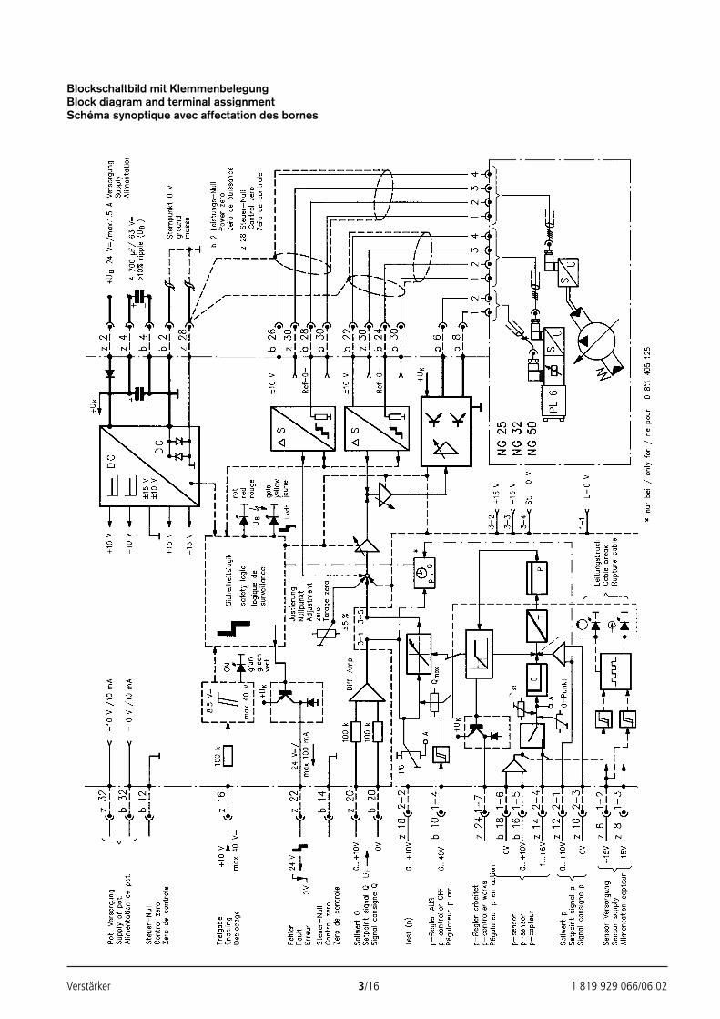
Verstärker 3/16 1 819 929 066/06.02
Blockschaltbild mit KlemmenbelegungBlock diagram and terminal assignmentSchéma synoptique avec affectation des bornes
23531_2978_002_016 13.06.2002 7:17 Uhr Seite 3
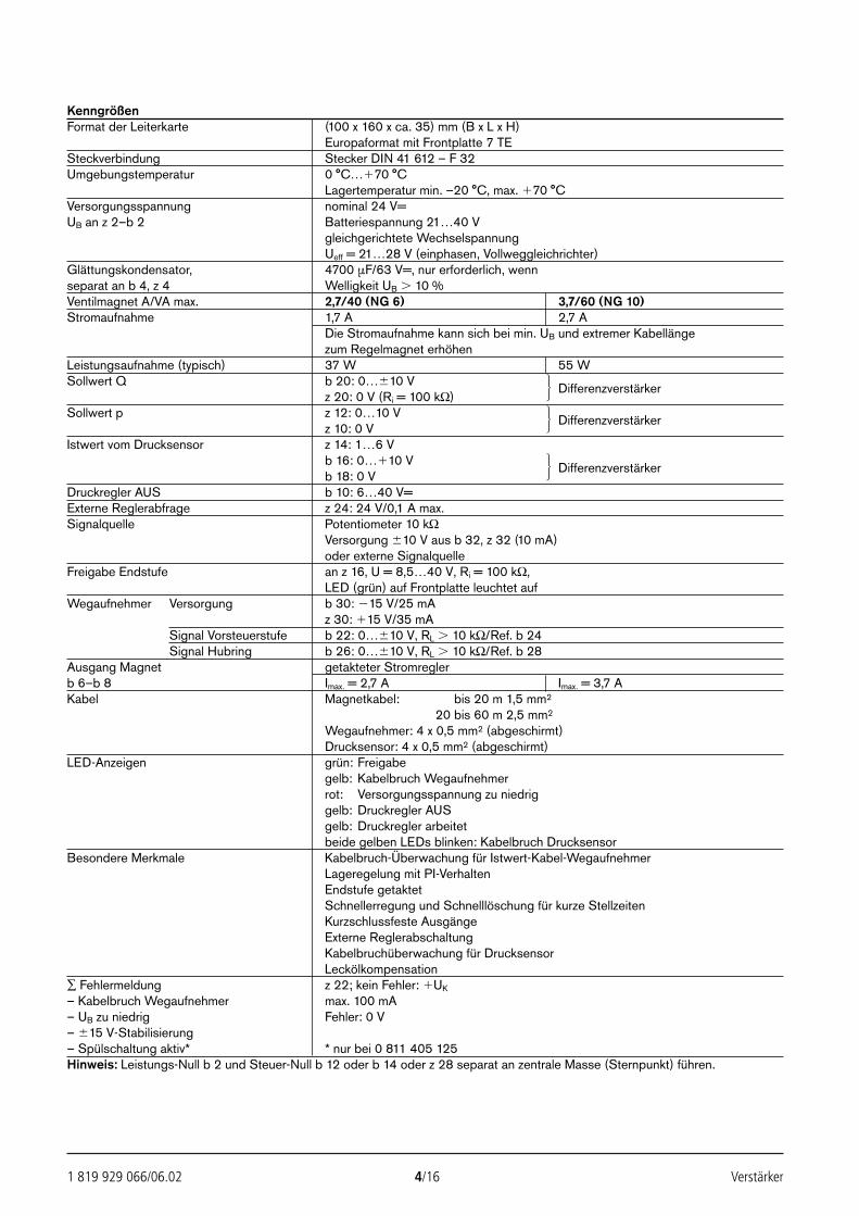
1 819 929 066/06.02 4/16 Verstärker
KenngrößenFormat der Leiterkarte (100 x 160 x ca. 35) mm (B x L x H)
Europaformat mit Frontplatte 7 TESteckverbindung Stecker DIN 41 612 – F 32Umgebungstemperatur 0 °C…70 °C
Lagertemperatur min. –20 °C, max. 70 °CVersorgungsspannung nominal 24 V=UB an z 2–b 2 Batteriespannung 21…40 V
gleichgerichtete WechselspannungUeff = 21…28 V (einphasen, Vollweggleichrichter)
Glättungskondensator, 4700 µF/63 V=, nur erforderlich, wennseparat an b 4, z 4 Welligkeit UB 10 %Ventilmagnet A/VA max. 2,7/40 (NG 6) 3,7/60 (NG 10)Stromaufnahme 1,7 A 2,7 A
Die Stromaufnahme kann sich bei min. UB und extremer Kabellängezum Regelmagnet erhöhen
Leistungsaufnahme (typisch) 37 W 55 WSollwert Q b 20: 0…10 V
z 20: 0 V (Ri = 100 kΩ)Differenzverstärker
Sollwert p z 12: 0…10 Vz 10: 0 V
Differenzverstärker
Istwert vom Drucksensor z 14: 1…6 Vb 16: 0…10 Vb 18: 0 V
Differenzverstärker
Druckregler AUS b 10: 6…40 V=Externe Reglerabfrage z 24: 24 V/0,1 A max.Signalquelle Potentiometer 10 kΩ
Versorgung 10 V aus b 32, z 32 (10 mA)oder externe Signalquelle
Freigabe Endstufe an z 16, U = 8,5…40 V, Ri = 100 kΩ,LED (grün) auf Frontplatte leuchtet auf
Wegaufnehmer Versorgung b 30: 15 V/25 mAz 30: 15 V/35 mA
Signal Vorsteuerstufe b 22: 0…10 V, RL 10 kΩ/Ref. b 24Signal Hubring b 26: 0…10 V, RL 10 kΩ/Ref. b 28
Ausgang Magnet getakteter Stromreglerb 6–b 8 Imax. = 2,7 A Imax. = 3,7 AKabel Magnetkabel: 20 bis 20 m 1,5 mm2
20 bis 60 m 2,5 mm2
Wegaufnehmer: 4 x 0,5 mm2 (abgeschirmt)Drucksensor: 4 x 0,5 mm2 (abgeschirmt)
LED-Anzeigen grün: Freigabegelb: Kabelbruch Wegaufnehmerrot: Versorgungsspannung zu niedriggelb: Druckregler AUSgelb: Druckregler arbeitetbeide gelben LEDs blinken: Kabelbruch Drucksensor
Besondere Merkmale Kabelbruch-Überwachung für Istwert-Kabel-WegaufnehmerLageregelung mit PI-VerhaltenEndstufe getaktetSchnellerregung und Schnelllöschung für kurze StellzeitenKurzschlussfeste AusgängeExterne ReglerabschaltungKabelbruchüberwachung für DrucksensorLeckölkompensation
∑ Fehlermeldung z 22; kein Fehler: UK
– Kabelbruch Wegaufnehmer max. 100 mA– UB zu niedrig Fehler: 0 V– 15 V-Stabilisierung– Spülschaltung aktiv* * nur bei 0 811 405 125Hinweis: Leistungs-Null b 2 und Steuer-Null b 12 oder b 14 oder z 28 separat an zentrale Masse (Sternpunkt) führen.
23531_2978_002_016 13.06.2002 7:17 Uhr Seite 4
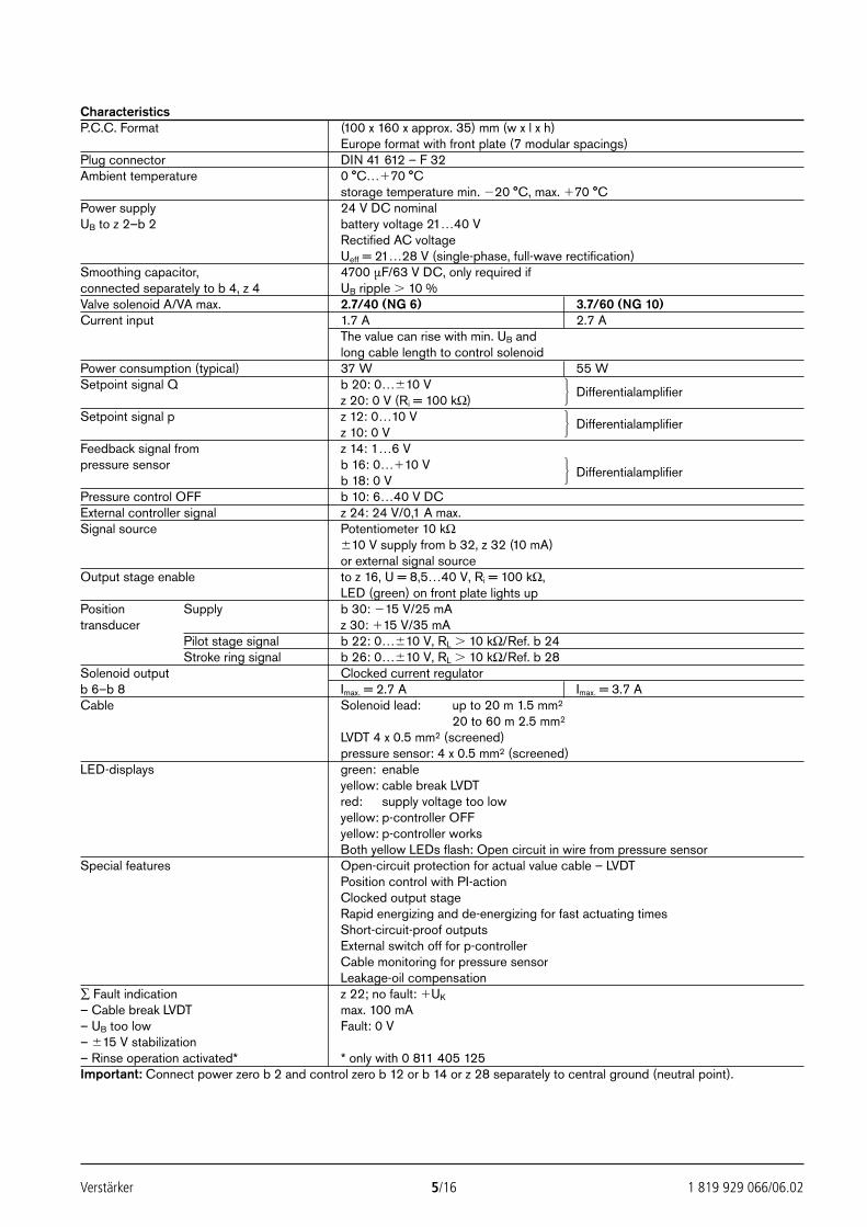
Verstärker 5/16 1 819 929 066/06.02
CharacteristicsP.C.C. Format (100 x 160 x approx. 35) mm (w x l x h)
Europe format with front plate (7 modular spacings)Plug connector DIN 41 612 – F 32Ambient temperature 0 °C…70 °C
storage temperature min. 20 °C, max. 70 °CPower supply 24 V DC nominalUB to z 2–b 2 battery voltage 21…40 V
Rectified AC voltageUeff = 21…28 V (single-phase, full-wave rectification)
Smoothing capacitor, 4700 µF/63 V DC, only required ifconnected separately to b 4, z 4 UB ripple 10 %Valve solenoid A/VA max. 2.7/40 (NG 6) 3.7/60 (NG 10)Current input 1.7 A 2.7 A
The value can rise with min. UB andlong cable length to control solenoid
Power consumption (typical) 37 W 55 WSetpoint signal Q b 20: 0…10 V
z 20: 0 V (Ri = 100 kΩ)Differentialamplifier
Setpoint signal p z 12: 0…10 Vz 10: 0 V
Differentialamplifier
Feedback signal from z 14: 1…6 Vpressure sensor b 16: 0…10 V
b 18: 0 VDifferentialamplifier
Pressure control OFF b 10: 6…40 V DCExternal controller signal z 24: 24 V/0,1 A max.Signal source Potentiometer 10 kΩ
10 V supply from b 32, z 32 (10 mA)or external signal source
Output stage enable to z 16, U = 8,5…40 V, Ri = 100 kΩ,LED (green) on front plate lights up
Position Supply b 30: 15 V/25 mAtransducer z 30: 15 V/35 mA
Pilot stage signal b 22: 0…10 V, RL 10 kΩ/Ref. b 24Stroke ring signal b 26: 0…10 V, RL 10 kΩ/Ref. b 28
Solenoid output Clocked current regulatorb 6–b 8 Imax. = 2.7 A Imax. = 3.7 ACable Solenoid lead: up to 20 m 1.5 mm2
20 to 60 m 2.5 mm2
LVDT 4 x 0.5 mm2 (screened)pressure sensor: 4 x 0.5 mm2 (screened)
LED-displays green: enableyellow: cable break LVDTred: supply voltage too lowyellow: p-controller OFFyellow: p-controller worksBoth yellow LEDs flash: Open circuit in wire from pressure sensor
Special features Open-circuit protection for actual value cable – LVDTPosition control with PI-actionClocked output stageRapid energizing and de-energizing for fast actuating timesShort-circuit-proof outputsExternal switch off for p-controllerCable monitoring for pressure sensorLeakage-oil compensation
∑ Fault indication z 22; no fault: UK
– Cable break LVDT max. 100 mA– UB too low Fault: 0 V– 15 V stabilization– Rinse operation activated* * only with 0 811 405 125Important: Connect power zero b 2 and control zero b 12 or b 14 or z 28 separately to central ground (neutral point).
23531_2978_002_016 13.06.2002 7:17 Uhr Seite 5
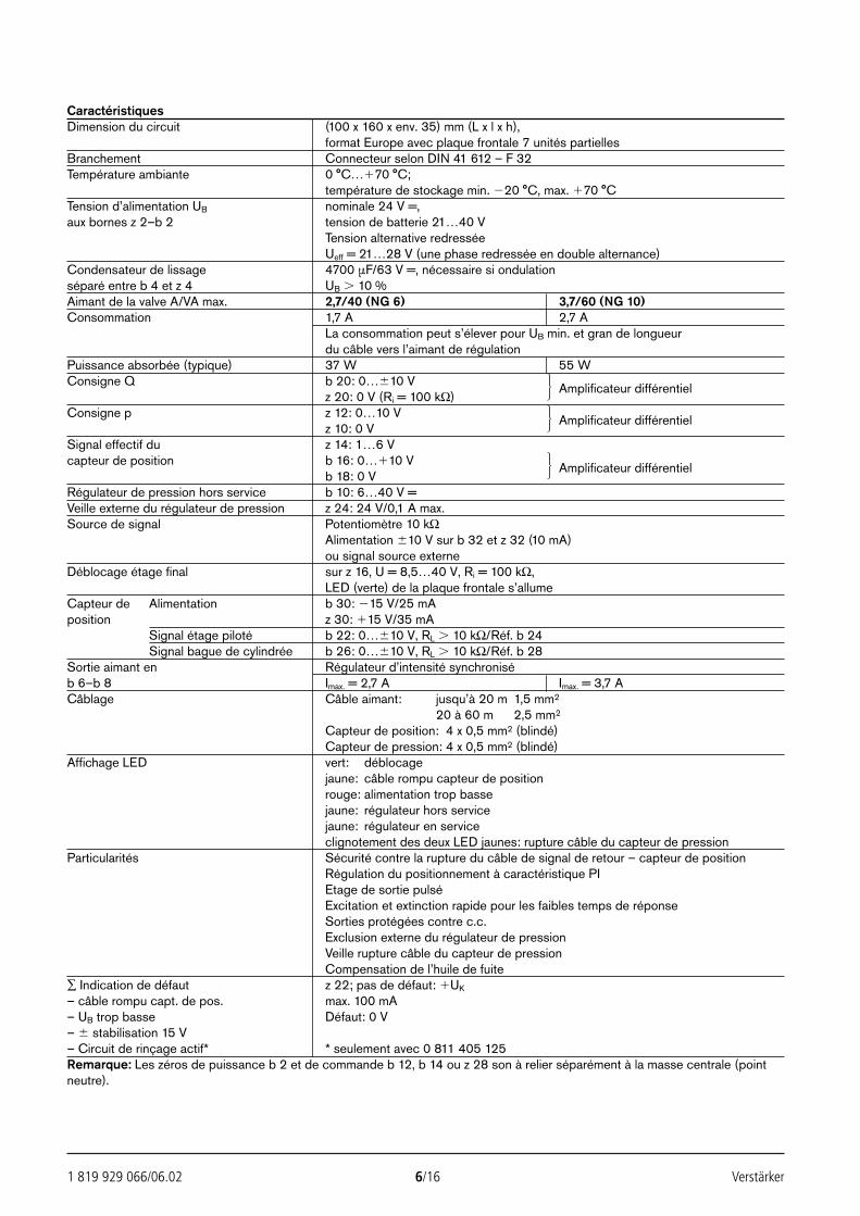
1 819 929 066/06.02 6/16 Verstärker
CaractéristiquesDimension du circuit (100 x 160 x env. 35) mm (L x l x h),
format Europe avec plaque frontale 7 unités partiellesBranchement Connecteur selon DIN 41 612 – F 32Température ambiante 0 °C…70 °C;
température de stockage min. 20 °C, max. 70 °CTension d’alimentation UB nominale 24 V =,aux bornes z 2–b 2 tension de batterie 21…40 V
Tension alternative redresséeUeff = 21…28 V (une phase redressée en double alternance)
Condensateur de lissage 4700 µF/63 V =, nécessaire si ondulationséparé entre b 4 et z 4 UB 10 %Aimant de la valve A/VA max. 2,7/40 (NG 6) 3,7/60 (NG 10)Consommation 1,7 A 2,7 A
La consommation peut s’élever pour UB min. et gran de longueurdu câble vers l’aimant de régulation
Puissance absorbée (typique) 37 W 55 WConsigne Q b 20: 0…10 V
z 20: 0 V (Ri = 100 kΩ)Amplificateur différentiel
Consigne p z 12: 0…10 Vz 10: 0 V
Amplificateur différentiel
Signal effectif du z 14: 1…6 Vcapteur de position b 16: 0…10 V
b 18: 0 VAmplificateur différentiel
Régulateur de pression hors service b 10: 6…40 V =Veille externe du régulateur de pression z 24: 24 V/0,1 A max.Source de signal Potentiomètre 10 kΩ
Alimentation 10 V sur b 32 et z 32 (10 mA)ou signal source externe
Déblocage étage final sur z 16, U = 8,5…40 V, Ri = 100 kΩ,LED (verte) de la plaque frontale s’allume
Capteur de Alimentation b 30: 15 V/25 mAposition z 30: 15 V/35 mA
Signal étage piloté b 22: 0…10 V, RL 10 kΩ/Réf. b 24Signal bague de cylindrée b 26: 0…10 V, RL 10 kΩ/Réf. b 28
Sortie aimant en Régulateur d’intensité synchroniséb 6–b 8 Imax. = 2,7 A Imax. = 3,7 ACâblage Câble aimant: jusqu’à 20 m 1,5 mm2
20 à 60 m 2,5 mm2
Capteur de position: 4 x 0,5 mm2 (blindé)Capteur de pression: 4 x 0,5 mm2 (blindé)
Affichage LED vert: déblocagejaune: câble rompu capteur de positionrouge: alimentation trop bassejaune: régulateur hors servicejaune: régulateur en serviceclignotement des deux LED jaunes: rupture câble du capteur de pression
Particularités Sécurité contre la rupture du câble de signal de retour – capteur de positionRégulation du positionnement à caractéristique PIEtage de sortie pulséExcitation et extinction rapide pour les faibles temps de réponseSorties protégées contre c.c.Exclusion externe du régulateur de pressionVeille rupture câble du capteur de pressionCompensation de l’huile de fuite
∑ Indication de défaut z 22; pas de défaut: UK
– câble rompu capt. de pos. max. 100 mA– UB trop basse Défaut: 0 V– stabilisation 15 V– Circuit de rinçage actif* * seulement avec 0 811 405 125Remarque: Les zéros de puissance b 2 et de commande b 12, b 14 ou z 28 son à relier séparément à la masse centrale (pointneutre).
23531_2978_002_016 13.06.2002 7:17 Uhr Seite 6
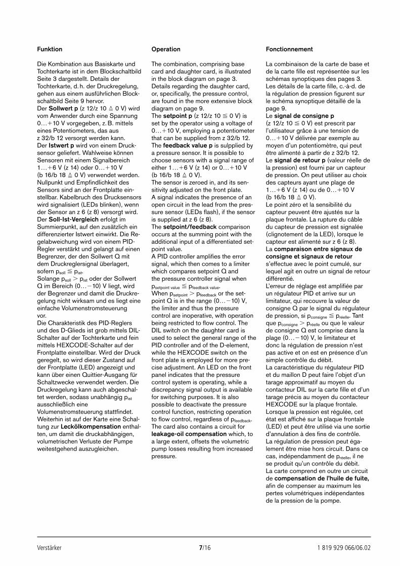
Verstärker 7/16 1 819 929 066/06.02
Funktion
Die Kombination aus Basiskarte undTochterkarte ist in dem BlockschaltbildSeite 3 dargestellt. Details derTochterkarte, d. h. der Druckregelung,gehen aus einem ausführlichen Block-schaltbild Seite 9 hervor.Der Sollwert p (z 12/z 10 0 V) wirdvom Anwender durch eine Spannung0…10 V vorgegeben, z. B. mittelseines Potentiometers, das aus z 32/b 12 versorgt werden kann.Der Istwert p wird von einem Druck-sensor geliefert. Wahlweise könnenSensoren mit einem Signalbereich 1…6 V (z 14) oder 0…10 V (b 16/b 18 0 V) verwendet werden.Nullpunkt und Empfindlichkeit desSensors sind an der Frontplatte ein-stellbar. Kabelbruch des Drucksensorswird signalisiert (LEDs blinken), wennder Sensor an z 6 (z 8) versorgt wird.Der Soll-Ist-Vergleich erfolgt imSummierpunkt, auf den zusätzlich eindifferenzierter Istwert einwirkt. Die Re-gelabweichung wird von einem PID-Regler verstärkt und gelangt auf einenBegrenzer, der den Sollwert Q mitdem Druckreglersignal überlagert,sofern psoll pist.Solange psoll pist oder der SollwertQ im Bereich (0…10) V liegt, wirdder Begrenzer und damit die Druckre-gelung nicht wirksam und es liegt eineeinfache Volumenstromsteuerung vor.Die Charakteristik des PID-Reglersund des D-Glieds ist grob mittels DIL-Schalter auf der Tochterkarte und feinmittels HEXCODE-Schalter auf derFrontplatte einstellbar. Wird der Druckgeregelt, so wird dieser Zustand aufder Frontplatte (LED) angezeigt undkann über einen Quittier-Ausgang fürSchaltzwecke verwendet werden. DieDruckregelung kann auch abgeschal-tet werden, sodass unabhängig pist
ausschließlich eineVolumenstromsteuerung stattfindet.Weiterhin ist auf der Karte eine Schal-tung zur Leckölkompensation enthal-ten, um damit die druckabhängigen,volumetrischen Verluste der Pumpeweitestgehend auszugleichen.
Operation
The combination, comprising basecard and daughter card, is illustratedin the block diagram on page 3.Details regarding the daughter card,or, specifically, the pressure control,are found in the more extensive blockdiagram on page 9.The setpoint p (z 12/z 10 0 V) isset by the operator using a voltage of0…10 V, employing a potentiometerthat can be supplied from z 32/b 12.The feedback value p is sulpplied bya pressure sensor. It is possible tochoose sensors with a signal range ofeither 1…6 V (z 14) or 0…10 V (b 16/b 18 0 V).The sensor is zeroed in, and its sen-sitivity adjusted on the front plate. A signal indicates the presence of anopen circuit in the lead from the pres-sure sensor (LEDs flash), if the sensoris supplied at z 6 (z 8).The setpoint/feedback comparisonoccurs at the summing point with theadditional input of a differentiated set-point value.A PID controller amplifies the errorsignal, which then comes to a limiterwhich compares setpoint Q andthe pressure controller signal whenpsetpoint value pfeedback value.When psetpoint pfeedback or the set-point Q is in the range (0…10) V,the limiter and thus the pressurecontrol are inoperative, with operationbeing restricted to flow control. TheDIL switch on the daughter card isused to select the general range of thePID controller and of the D-element,while the HEXCODE switch on thefront plate is employed for more pre-cise adjustment. An LED on the frontpanel indicates that the pressurecontrol system is operating, while adiscrepancy signal output is availablefor switching purposes. It is alsopossible to deactivate the pressurecontrol function, restricting operationto flow control, regardless of pfeedback.The card also contains a circuit forleakage-oil compensation which, toa large extent, offsets the volumetricpump losses resulting from increasedpressure.
Fonctionnement
La combinaison de la carte de base etde la carte fille est représentée sur lesschémas synoptiques des pages 3.Les détails de la carte fille, c.-à-d. dela régulation de pression figurent surle schéma synoptique détaillé de lapage 9.Le signal de consigne p(z 12/z 10 0 V) est prescrit parl’utilisateur grâce à une tension de 0…10 V délivrée par exemple aumoyen d’un potentiomètre, qui peutêtre alimenté à partir de z 32/b 12.Le signal de retour p (valeur réelle dela pression) est fourni par un capteurde pression. On peut utiliser au choixdes capteurs ayant une plage de 1…6 V (z 14) ou de 0…10 V (b 16/b 18 0 V).Le point zéro et la sensibilité ducapteur peuvent être ajustés sur laplaque frontale. La rupture du câbledu capteur de pression est signalée(clignotement de la LED), lorsque lecapteur est alimenté sur z 6 (z 8).La comparaison entre signaux deconsigne et signaux de retours’effectue avec le point cumulé, surlequel agit en outre un signal de retourdifférentié.L’erreur de réglage est amplifiée parun régulateur PID et arrive sur unlimitateur, qui recouvre la valeur deconsigne Q par le signal du régulateurde pression, si pconsigne préelle. Tantque pconsigne préelle ou que le valeurde consigne Q est comprise dans laplage (0…10) V, le limitateur etdonc la régulation de pression n’estpas active et on est en présence d’unsimple contrôle du débit. La caractéristique du régulateur PIDet du maillon D peut faire l’objet d’untarage approximatif au moyen ducontacteur DIL sur la carte fille et d’untarage précis au moyen du contacteurHEXCODE sur la plaque frontale.Lorsque la pression est régulée, cetétat est affiché sur la plaque frontale(LED) et peut être utilisé via une sortied’annulation à des fins de contrôle.La régulation de pression peut éga-lement être mise hors circuit. Dans cecas, indépendamment de préelle, il nese produit qu’un contrôle du débit.La carte comprend en outre un circuitde compensation de l’huile de fuite,afin de compenser au maximum lespertes volumétriques indépendantesde la pression de la pompe.
23531_2978_002_016 13.06.2002 7:17 Uhr Seite 7
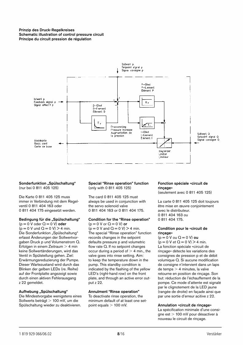
1 819 929 066/06.02 8/16 Verstärker
Prinzip des Druck-RegelkreisesSchematic illustration of control pressure circuitPrincipe du circuit pression de régulation
Sonderfunktion „Spülschaltung“(nur bei 0 811 405 125)
Die Karte 0 811 405 125 muss immer in Verbindung mit dem Regel-ventil 0 811 404 163 oder 0 811 404 175 eingesetzt werden.
Bedingung für die „Spülschaltung“(p = 0 V oder Q = 0 V) oder(p = 0 V und Q = 0 V) > 4 min.Die Sonderfunktion „Spülschaltung“erfasst Änderungen der Sollwertvor-gaben Druck p und Volumenstrom Q.Erfolgen in einem Zeitraum 4 minkeine Sollwertänderungen, wird dasVentil in Spülstellung gehen. Ziel:Erwärmungsreduzierung der Pumpe.Dieser Wartezustand wird durch dasBlinken der gelben LEDs (re. Reihe)auf der Frontplatte angezeigt sowiedurch einen aktiven Fehlerausgangz 22 gemeldet.
Aufhebung „Spülschaltung“Die Mindestvorgabe wenigstens einesSollwerts beträgt 100 mV, um dieSpülschaltung wieder zu deaktivieren.
Special “Rinse operation” function(only with 0 811 405 125)
The card 0 811 405 125 must always be used in conjunction with the servo solenoid valve 0 811 404 163 or 0 811 404 175.
Condition for the “Rinse operation”(p = 0 V or Q = 0 V) or(p = 0 V and Q = 0 V) > 4 min.The special “Rinse operation” functionrecords changes in the setpointdefaults pressure p and volumetricflow rate Q. If no setpoint changesoccur during a period of 4 min., thevalve goes into rinse setting. Aim: to keep the temperature down in thepump. This standby condition isindicated by the flashing of the yellowLED’s (right-hand row) on the frontplate, and through an active error out-put z 22.
Annulment “Rinse operation”To deactivate rinse operation, theminimum default of at least one set-point equals 100 mV.
Fonction spéciale «circuit derinçage»(seulement avec 0 811 405 125)
La carte 0 811 405 125 doit toujoursêtre mise en œuvre conjointementavec le distributeur.0 811 404 163 ou 0 811 404 175.
Condition pour le «circuit derinçage»(p = 0 V ou Q = 0 V) ou(p = 0 V et Q = 0 V) > 4 min.La fonction spéciale «circuit derinçage» détecte les variations desconsignes de pression p et de débitvolumique Q. Si aucune modificationde consigne n’intervient dans un lapsde temps 4 minutes, la valveretourne en position de rinçage. Sonbut: réduction de l’échauffement de lapompe. Ce mode d’attente est signalépar le clignotement de la LED jaune(rangée de droite) en façade ainsi quepar une sortie d’erreur acitive z 22.
Annulation «circuit de rinçage»La spécification minimale d’une consi-gne est 100 mV pour désactiver ànouveau le circuit de rinçage.
23531_2978_002_016 13.06.2002 7:17 Uhr Seite 8
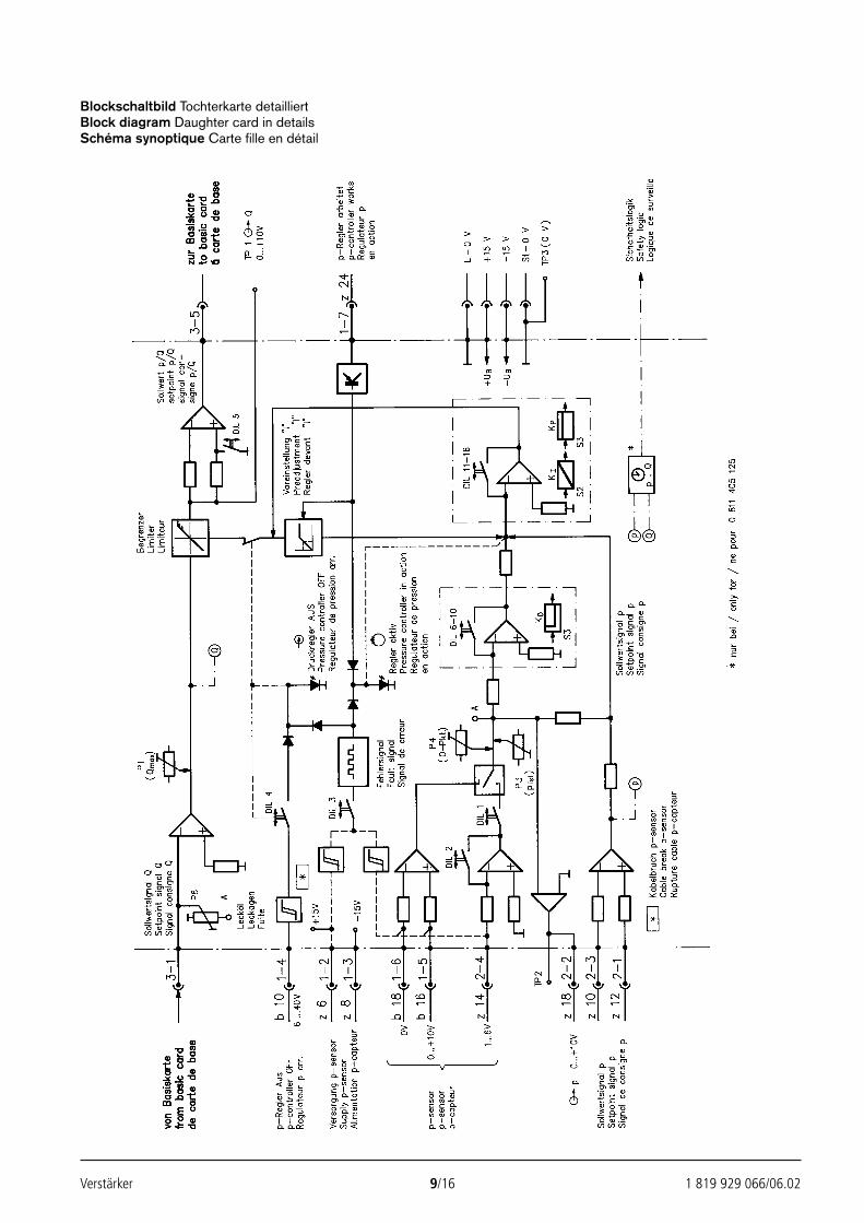
Verstärker 9/16 1 819 929 066/06.02
Blockschaltbild Tochterkarte detailliertBlock diagram Daughter card in detailsSchéma synoptique Carte fille en détail
23531_2978_002_016 13.06.2002 7:17 Uhr Seite 9
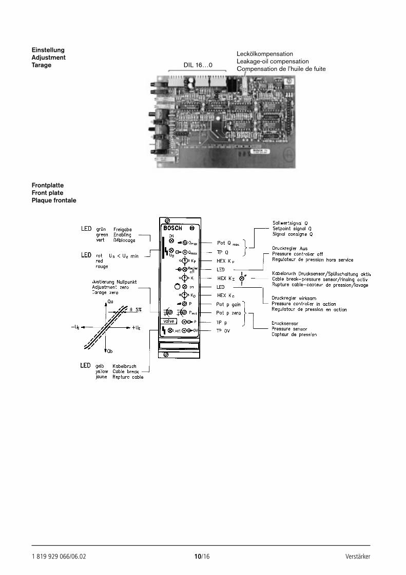
1 819 929 066/06.02 10/16 Verstärker
EinstellungAdjustmentTarage
FrontplatteFront platePlaque frontale
DIL 16…0
LeckölkompensationLeakage-oil compensationCompensation de l’huile de fuite
23531_2978_002_016 13.06.2002 7:17 Uhr Seite 10
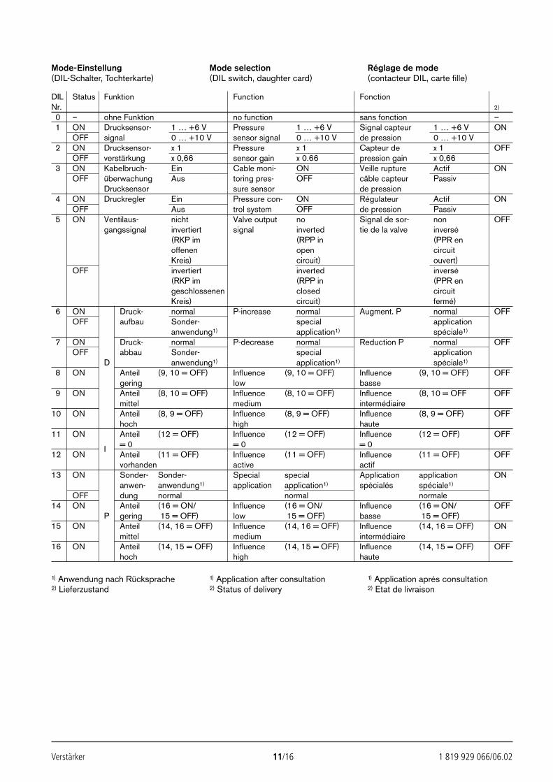
Verstärker 11/16 1 819 929 066/06.02
Mode-Einstellung(DIL-Schalter, Tochterkarte)
Mode selection(DIL switch, daughter card)
Réglage de mode(contacteur DIL, carte fille)
DIL Status Funktion Function FonctionNr. 2)
0 – ohne Funktion no function sans fonction –1 ON Drucksensor- 1 … +6 V Pressure 1 … +6 V Signal capteur 1 … +6 V ON
OFF signal 0 … +10 V sensor signal 0 … +10 V de pression 0 … +10 V2 ON Drucksensor- x 1 Pressure x 1 Capteur de x 1 OFF
OFF verstärkung x 0,66 sensor gain x 0.66 pression gain x 0,663 ON Kabelbruch- Ein Cable moni- ON Veille rupture Actif ON
OFF überwachung Aus toring pres- OFF câble capteur PassivDrucksensor sure sensor de pression
4 ON Druckregler Ein Pressure con- ON Régulateur Actif ONOFF Aus trol system OFF de pression Passiv
5 ON Ventilaus- nicht Valve output no Signal de sor- non OFFgangssignal invertiert signal inverted tie de la valve inversé
(RKP im (RPP in (PPR enoffenen open circuitKreis) circuit) ouvert)
OFF invertiert inverted inversé(RKP im (RPP in (PPR engeschlossenen closed circuitKreis) circuit) fermé)
6 ON Druck- normal P-increase normal Augment. P normal OFFOFF aufbau Sonder- special application
anwendung1) application1) spéciale1)
7 ON Druck- normal P-decrease normal Reduction P normal OFFOFF abbau Sonder- special application
D anwendung1) application1) spéciale1)
8 ON Anteil (9, 10 = OFF) Influence (9, 10 = OFF) Influence (9, 10 = OFF) OFFgering low basse
9 ON Anteil (8, 10 = OFF) Influence (8, 10 = OFF) Influence (8, 10 = OFF OFFmittel medium intermédiaire
10 ON Anteil (8, 9 = OFF) Influence (8, 9 = OFF) Influence (8, 9 = OFF) OFFhoch high haute
11 ON Anteil (12 = OFF) Influence (12 = OFF) Influence (12 = OFF) OFF
I = 0 = 0 = 012 ON Anteil (11 = OFF) Influence (11 = OFF) Influence (11 = OFF) OFF
vorhanden active actif13 ON Sonder- Sonder- Special special Application application ON
anwen- anwendung1) application application1) spécialés spéciale1)
OFF dung normal normal normale14 ON Anteil (16 = ON/ Influence (16 = ON/ Influence (16 = ON/ OFF
P gering 15 = OFF) low 15 = OFF) basse 15 = OFF)15 ON Anteil (14, 16 = OFF) Influence (14, 16 = OFF) Influence (14, 16 = OFF) ON
mittel medium intermédiaire16 ON Anteil (14, 15 = OFF) Influence (14, 15 = OFF) Influence (14, 15 = OFF) OFF
hoch high haute
1) Anwendung nach Rücksprache2) Lieferzustand
1) Application after consultation2) Status of delivery
1) Application aprés consultation2) Etat de livraison
23531_2978_002_016 13.06.2002 7:17 Uhr Seite 11
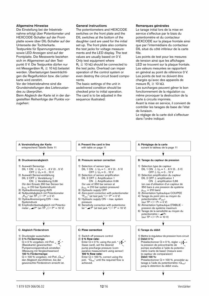
1 819 929 066/06.02 12/16 Verstärker
Allgemeine HinweiseDie Einstellung bei der Inbetrieb-nahme erfolgt über Potentiometer undHEXCODE-Schalter auf der Front-platte sowie über DIL-Schalter auf derUnterseite der Tochterkarte. Testpunkte für Spannungsmessungensowie LED-Anzeigen sind auf derFrontplatte. Die Messwerte beziehensich im Allgemeinen auf den Test-punkt 0 V. Die Testpunkte dürfen nurmit Messgeräten RL 10 kΩ belastetwerden. Überlastungen beeinträchti-gen die Regelfunktion bzw. die Leiter-karte wird zerstört.Vor der Inbetriebnahme sind dieGrundeinstellungen des Lieferzustan-des zu überprüfen.Beim Abgleich der Karte ist in der dar-gestellten Reihenfolge der Punkte vor-zugehen:
General instructionsThe potentiometers and HEXCODEswitches on the front plate and theDIL switches at the bottom of thedaughter card are used for the initialset-up. The front plate also containsthe test jacks for voltage measure-ments and the LED display. The testvalues are usually based on 0 V.Only test equipment where RL 10 kΩ should be connected tothe test jacks. Overload can impairoperation of the control system oreven destroy the circuit board compo-nents.The basic settings of the unit inasdelivered condition should bechecked prior to initial operation. The card is to be adjusted in thesequence illustrated:
Remarques généralesLe tarage initial lors de la mise enservice s’effectue par le biais dupotentiomètre et du contacteurHEXCODE sur la plaque frontale ainsique par l’intermédiaire du contacteurDIL situé du côté inférieur de la cartefille.Les points de test pour les mesuresde tension ainsi que les affichagesLED se trouvent sur la plaque frontale.Les valeurs mesurées se rapportenten général au point de référence 0 V.Les points de test ne doivent êtrechargés qu’avec des appareils demesure RL 10 kΩ.Les surcharges peuvent gêner le bonfonctionnement de la régulation oumême provoquer la destruction de lacarte à circuits imprimés.Avant la mise en service, il convient decontrôler les tarages de base de l’étatde livraison.Le réglage de la carte doit s’effectuerdans l’ordre indiqué:
A: Voreinstellung der Karteentsprechend Tabelle Seite 11
A: Present the card in linewith table on page 11
A: Péréglage de la cartesuivant le tableau de la page 11
B: Drucksensorabgleich
1) Auswahl SensortypDIL 1 ON UA = 1…6 V (0…5 V)
OFF UA = 0…10 V2) Auswahl Sensorverstärkung
DIL 2 OFF Verstärkung 1DIL 2 ON Verstärkung 0,66(für den Einsatz 350 bar Sensor beipmax. = 210 bar Systemdruck)
3) Hydraulikversorgung AUS4) Nullpunktabgleich mit Potentiometer
„PNull“ (an TP „ P“ = 0 V)5) Hydraulikversorgung EIN – max.
Systemdruck6) Empfindlichkeitsabgleich mit Potentio-
meter „ P“ (an TP „ P“ = 10 V)
C: Abgleich Förderstrom
1) Druckregler ausschalten2) 0 %-Fördermenge:
Q = 0 % vorgeben, mit Poti (Basiskarte) gewünschtenPumpenvorspanndruck einstellen(Messung mit Vergleichssensor)100 %-Fördermenge:Q = 100 % vorgeben, mit Poti „Qmax“den Abgleich durchführen, bis dergewünschte Förderstrom erreicht ist.
C: Flow correction
1) Switch off pressure control2) 0 % flow rate:
Enter Q = 0 %; using the poti. (base card), set the desiredpump precharge pressure (com-parative measurement using sensor)100 % flow rate:Enter Q = 100 %, correct using the poti. “Qmax” until the required flow isachieved.
C: Tarage du débit
1) Mettre le régulateur de pression hors circuit2) Débit 0 %:
Présélectionner Q = 0 %, régler la pression de précontrainte depompe souhaitée à l’aide du potentio-mètre (carte de base) (mesure avecle capteur de comparaison)Débit 100 %:Présélectionner Q = 100 %, procéder autarage à l’aide du potentiomètre «Qmax»jusqu’à obtention du débit voulu.
B: Pressure sensor correction
1) Selection of sensor typeDIL 1 ON UA = 1…6 V (0…5 V)
OFF UA = 0…10 V2) Selection of sensor amplification
DIL 2 OFF Amplification 1DIL 2 ON Amplification 0.66(for use of 350 bar sensor atpmax. = 210 bar system pressure)
3) Hydraulic supply OFF4) Zero-point correction with potentiometer
“Pzero” (at test jack “ P” = 0 V)5) Hydraulic supply ON – max. system
pressure6) Sensitivity correction with potentiome-
ter “ P” (at test jack “ P” = 10 V)
B: Tarage du capteur de pression
1) Sélection type de capteurDIL 1 ON UA = 1…6 V (0…5 V)
OFF UA = 0…10 V2) Sélection amplification du capteur
DIL 2 OFF amplification 1DIL 2 ON amplification 0,66(en cas d’utilisation d’un capteur de350 bars à une pression de système pmax. = 210 bars)
3) Alimentation hydraulique COUPEE4) Tarage du point zéro au moyen du
potentiomètre «Pzéro» (sur TP « P» = 0 V)
5) Alimentation hydraulique ETABLIE – pression de système maximum
6) Tarage de la sensibilité au moyen dupotentiomètre « P» (sur TP « P» = 10 V)
23531_2978_002_016 13.06.2002 7:17 Uhr Seite 12
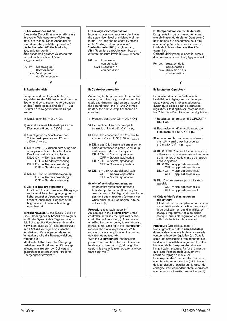
Verstärker 13/16 1 819 929 066/06.02
D: LeckölkompensationSteigender Druck führt zu einer Abnahmedes realen Volumenstroms (Wirkungs-grad) der Pumpe. Diese Abhängigkeit kann durch die „Leckölkompensation“„Potentiometer P6“ (Tochterkarte)ausgeglichen werden.Ziel: annähernd gleicher Volumenstrombei unterschiedlichen Drücken(Qsoll = const.)
P6 cw: Erhöhung derKompensation
ccw: Verringerungder Kompensation
D: Leakage-oil compensationIncreasing pressure leads to a decline inthe actual flow (level of efficiency) of the pump. This loss can be offset by meansof the “leakage-oil compensation”“potentiometer P6” (daughter card).Aim: To achieve a roughly even flow atdifferent pressure levels (Qsetpoint = const.)
P6 cw: Increase incompensation
ccw: Reduction incompensation
D: Compensation de l’huile de fuiteL’augmentation de la pression entraîneune diminution du débit réel (rendement)de la pompe. Ce phénomène peut êtrecompensé grâce à la «compensation del’huile de fuite» «potentiomètre P6»(carte fille).Objectif: débit presque indentique pourdes pressions différentes (Qcons. = const.)
P6 cw: élévation de lacompensation
ccw: diminution de lacompensation
E: Reglerabgleich
Entsprechend den Eigenschaften derRegelstrecke, der Störgrößen und den sta-tischen und dynamischen Anforderungen an das Regelergebnis sind die P-, I- und D-Anteile des Regelverstärkers zu opti-mieren.
1) Druckregler EIN – DIL 4 ON
2) Anschluss eines Oszilloskops an denKlemmen z18 und b12 (0 V) pist
3) Günstigerweise Anschluss eines2. Oszilloskopkanals an z12 und z10 (0 V) psoll
4) DIL 6 und DIL 7 dienen dem Ausgleichvon dynamischen Unterschieden imDruckauf- und -abbau im SystemDIL 6 ON = Normalanwendung
OFF = SonderanwendungDIL 7 ON = Normalanwendung
OFF = Sonderanwendung
5) DIL 13 – nur für SonderanwendungDIL 6 ON = Normalanwendung
OFF = Sonderanwendung
6) Ziel der RegleroptimierungEs ist ein Optimum zwischen Übergangs-verhalten (Überschwingneigung bei zuhoher statischer Verstärkung) und sta-tischer Genauigkeit (Regelfehler beibeginnender Druckabschneidung) zuerreichen (a).
Vorgehensweise (siehe Tabelle Seite 14)Eine Erhöhung des p-Anteils des Reglers erhöht die Dynamik des Regelverhaltens(b). Bei zu großer Verstärkung nimmt dieSchwingneigung zu (c). Eine Begrenzungdes I-Anteils verringert die statische Verstärkung. Mit steigender statischer Verstärkung wird die Regelabweichung verringert (d).Mit dem D-Anteil kann das Übergangs-verhalten beeinflusst werden (Schwing-neigung minimieren), der Sollwert wirddadurch aber erst nach einer größerenÜbergangszeit erreicht (f).
E: Controller correction
According to the properties of the control system, the influencing quantities and thestatic and dynamic requirements made ofthe control result, the P, I and D compo-nents of the control amplifier should beoptimized.
1) Pressure controller ON – DIL 4 ON
2) Connection of an oscilloscope to terminals z18 and b12 (0 V) pact
3) Favorable connection of a 2nd oscillo-scope to z12 and z10 (0 V) psetpoint
4) DIL 6 and DIL 7 serve to correct the dy-namic differences in pressure build-upand pressure drop in the systemDIL 6 ON = Normal application
OFF = Special applicationDIL 7 ON = Normal application
OFF = Special application
5) DIL 13 – only for special applicationDIL 6 ON = Special application
OFF = Normal application
6) Aim of controller optimizationAn optimum relationship betweentransition performance (tendency toovershooting at too high static amplifica-tion) and static accuracy (control errorwhen pressure cut-off begins) is to beachieved (a).
Procedure (see table page 14)An increase in the p component of the controller increases the dynamics of thecontroller performance (b). At excessiveamplification the tendency to overshootingincreases (c). Limiting of the I componentreduces the static amplification. Withincreasing static amplification the controldeviation decreases (d).With the D component the transitionperformance can be influenced (minimizetendency to overshooting), although thesetpoint is thus only reached after a longertransition time (f).
E: Tarage du régulateur
En fonction des caractéristiques del’installation à régler, des grandeurs per-tubatrices et des critères statiques etdynamiques exigés pour le résultat derégulation, il faut optimiser les composan-tes P, I et D de l’amplificateur de régulation.
1) Régulateur de pression EN CIRCUIT –DIL 4 ON
2) Raccordement d’un oscilloscope aux bornes z18 et b12 (0 V) peff
3) A un endroit favorable, raccordement d’un 2ème canal d’oscilloscope sur z12 et z10 (0 V) pconsigne
4) DIL 6 et DIL 7 servent à compenser lesdifférences dynamiques existant au coursde la montée et de la chute de pressiondans le systèmeDIL 6 ON = application normale
OFF = application spécialeDIL 7 ON = application normale
OFF = application spéciale
5) DIL 13 – uniquement pour utilisationspécialeDIL 6 ON = application spéciale
OFF = application normale
6) Objectif de l’optimisation durégulateur:Il faut rechercher un optimum (a) entre lacaractéristique de transition (tendance àla suroscillation en cas d’amplificationstatique trop élevée) et la précisionstatique (erreur de régulation en cas dedébut de limitation de pression).
Procédure (voir tableau page 14)Une augmentation de la composante pdu régulateur améliore la dynamique de lacaractéristique de régulation (b). Dans le cas d’une amplification trop importante, latendance à l’oscillation augmente (c). Unelimitation de la composante I diminuel’amplification statique. Au fur et à mesureque l’amplification statique augmente, l’écart de réglage diminue (d).La composante D permet d’influencer lacaractéristique de transition (minimisationde la tendance à l’oscillation), la valeur deconsigne n’est cependant obtenue qu’aprèsune période de transition assez longue (f).
23531_2978_002_016 13.06.2002 7:17 Uhr Seite 13
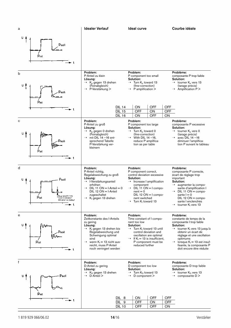
1 819 929 066/06.02 14/16 Verstärker
Idealer Verlauf Ideal curve Courbe idéale
Problem:P-Anteil zu kleinLösung: Kp gegen 13 drehen
(Feinabgleich) P-Verstärkung >
Problem:P component too smallSolution: Turn Kp toward 13
(fine-correction) P amplification >
Problème:composante P trop faibleSolution: tourner Kp vers 13
(tarage précis) Amplification P >
Problem:P-Anteil zu großLösung: Kp gegen 0 drehen
(Feinabgleich) mit DIL 14 –16 ent-
sprechend TabelleP-Verstärkung ver-kleinern
Problem:P component too largeSolution: Turn Kp toward 0
(fine-correction) With DIL 14 –16,
reduce P amplifica-tion as per table
Problème:composante P excessiveSolution: tourner Kp vers 0
(tarage précis) avec DIL 14 –16
diminuer l’amplifica-tion P suivant le tableau
Problem:P-Anteil richtig,Regelabweichung zu großLösung: I-Verstärkungsanteil
erhöhen DIL 11 ON = I-Anteil = 0
DIL 12 ON = I-Anteilzugeschaltet
KI gegen 13 drehen
Problem:P component correct,control deviation excessiveSolution: Increase I amplification
component DIL 11 ON = I compo-
nent = 0DIL 12 ON = I compo-nent switched
Turn KI toward 13
Problème:composante P correcte,écart de réglage tropimportantSolution: augmenter la compo-
sante d’amplification I DIL 11 ON = compo-
sante I = 0DIL 12 ON = compo-sante I enclenchés
tourner KI vers 13
Problem:Zeitkonstante des I-Anteilszu geringLösung: KI gegen 13 drehen bis
Regelabweichung undSchwingung optimalsind
wenn KI = 13 nicht aus-reicht, muss P-Anteilnoch verringert werden
Problem:Time constant of I compo-nent too lowSolution: Turn KI toward 13 until
control deviation andoscillation are optimal
If KI = 13 is insufficient,P component must bereduced further
Problème:constante de temps de lacomposante I trop faibleSolution: tourner KI vers 13 jusqu’à
obtenir un écart deréglage et une oscillationoptimums
lorsque KI = 13 est insuf-fisante, la composante Pdoit encore être réduite
Problem:D-Anteil zu geringLösung: KD gegen 13 drehen D-Anteil >
Problem:D component too lowSolution: Turn KD toward 13 D component >
Problème:composante D trop faibleSolution: tourner KD vers 13 composante D >
a
b
c
d
e
f
DIL 14 ON OFF OFFDIL 15 OFF ON OFFDIL 16 ON OFF ON
DIL 8 ON OFF OFFDIL 9 OFF ON OFFDIL 10 OFF OFF ON
23531_2978_002_016 13.06.2002 7:17 Uhr Seite 14

Verstärker 15/16 1 819 929 066/06.02
EinstellprotokollSet-up reportProtocole de tarage
Schalter LieferzustandSwitch State of deliveryContacteur Etat de livraison
Erstellt vonPrepared by DIL 1 ONFait par
DIL 2 OFF
Datum DIL 3 ONDate
DIL 4 ON
DIL 5 OFF
DIL 6 OFF
DIL 7 OFF
DIL 8 OFF
DIL 9 ON
DIL-switchDIL 10 OFF
DIL 11 OFF
DIL 12 OFF
DIL 13 ON
HEXCODE-DIL
DIL 14 OFF
DIL 15 ON
DIL 16 OFF
HEX KP 2
HEX KI 1
HEX KD 5
23531_2978_002_016 13.06.2002 7:17 Uhr Seite 15

Bosch Rexroth AG Die angegebenen Daten dienen allein derIndustrial Hydraulics Produktbeschreibung. Eine Aussage über eineD-97813 Lohr am Main bestimmte Beschaffenheit oder eine Eignung fürZum Eisengießer 1 D-97816 Lohr am Main einen bestimmten Einsatzzweck kann ausTelefon 0 93 52/18-0 unseren Angaben nicht abgeleitet werden. Es istTelefax 0 93 52/18-23 58 Telex 6 89 418-0 zu beachten, dass unsere Produkte einemeMail [email protected] natürlichen Verschleiß- und AlterungsprozessInternet www.boschrexroth.de unterliegen.
1 819 929 066/06.02 16/16 Verstärker
23531_2978_U1_U4 13.06.2002 7:14 Uhr Seite 16
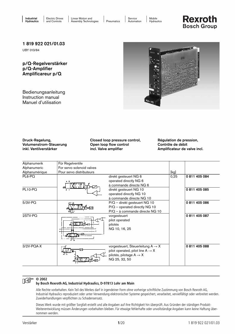
Industrial Electric Drives Linear Motion and Service MobileHydraulics and Controls Assembly Technologies Pneumatics Automation Hydraulics
1 819 922 021/01.03UBY 013/84
p/Q-Regelverstärkerp/Q-AmplifierAmplificareur p/Q
BedienungsanleitungInstruction manualManuel d’utilisation
© 2002by Bosch Rexroth AG, Industrial Hydraulics, D-97813 Lohr am Main
Alle Rechte vorbehalten. Kein Teil des Werkes darf in irgendeiner Form ohne vorherige schriftliche Zustimmung von Bosch Rexroth AG,Industrial Hydraulics reproduziert oder unter Verwendung elektronischer Systeme gespeichert, verarbeitet, vervielfältigt oder verbreitet werden.Zuwiderhandlungen verpflichten zu Schadensersatz.
Dieses Werk wurde mit größter Sorgfalt erstellt und alle Angaben auf ihre Richtigkeit hin überprüft. Aus Gründen der ständigen Produkt-Weiterentwicklung müssen Änderungen vorbehalten bleiben. Für etwaige fehlerhafte oder unvollständige Angaben kann keine Haftung über-nommen werden.
Verstärker 1/20 1 819 922 021/01.03
Druck-Regelung,Volumenstrom-Steuerunginkl. Ventilverstärker
Closed loop pressure control,Open loop flow controlincl. Valve amplifier
Régulation de pression,Contrôle de débitAmplificateur de valve incl.
Alphanumerik Für RegelventileAlphanumeric For servo solenoid valvesAlphanumérique Pour servo distributeurs [kg]PL6-PQ direkt gesteuert NG 6 0,25 0 811 405 084
operated directly NG 6à commande directe NG 6
PL10-PQ direkt gesteuert NG 10 0 811 405 085operated directly NG 10à commande directe NG 10
5/3V-PQ P/Q – direkt gesteuert NG 10 0 811 405 086P/Q – operated directly NG 10P/Q – à commande directe NG 10
2STV-PQ vorgesteuert 0 811 405 087pilot operated pilotésNG 10, 16, 25
3/2V-PQA-X vorgesteuert, Steuerleitung A X 0 811 405 088pilot operated, pilot line A Xpilotés, pilotage A XNG 25, 32, 50
24351_4027_001-020 13.02.2003 13:53 Uhr Seite 1
1 819 922 021/01.03 2/20 Verstärker
Inhalt Seite
Anwendungen 2Blockschaltbild 5Kenngrößen 7Funktion 10Einstellung 13Einstellprotokoll 18Abmessungen 19
Anwendungen
Die p/Q-Regelverstärker bestehen aus einer Basiskarte mit Frontplatte,welche den Ventilverstärker mitLageregelung enthält, sowie einer auf-gesteckten Tochterkarte, auf der dieeigentliche Druckregelung realisiertist.Diese Verstärker werden nur als voll-ständige Kombinationen geliefert.In Verbindung mit den entsprechen-den Regelventilen (siehe Tabelle Seite 1) und Drucksensoren (Aus-gangssignal 1…6 V oder 0…10 V)können Volumenströme gesteuert undDrücke im geschlossenen Regelkreisgeregelt werden.Eingangsgrößen sind die Sollwertevon Druck p und Volumenstrom Q. AlsIstwerte werden Druck- und Ventil-schieber-Weg rückgeführt. DieKombination von Ventilverstärker undp/Q-Regler wirkt:a) solange psoll > pist wie eine
Volumenstromsteuerung, d. h. die Druckregelung wird noch nichtwirksam.
b) erreicht psoll pist, so wird dieDruckregelung wirksam, d. h. einBegrenzer überlagert Sollwert Q.Die Tochterkarte gibt ein p/Q-Summensignal an die Basiskarteweiter.
Der Sollwert Q entspricht demSchieberweg, solange die Druck-regelung noch nicht wirksam ist, d. h.psoll > pist oder wenn der Druckreglerabgeschaltet ist (siehe Seite 14 DIL 4 OFF). Der Sollwert Q kann imBereich UE = 0…±10 V liegen.Für eine wirksame Druckregelungmuss jedoch neben dem Sollwert pauch ein Sollwert Q, UE 2…+10 Vanliegen.
Contents Page
Applications 2Block diagram 5Characteristics 8Function 10Adjustment 13Set-up report 18Dimensions 19
Applications
The p/Q-amplifier comprises a basecard with front plate, containing thevalve amplifier with position control,and a daughter card. The daughtercard, inserted in the base card, iswhere the actual pressure controlprocess occurs. This amplifier is onlyavailable as a single combination unit.When used together with the ap-propriate servo solenoid valves (see table on page 1) and pressuresensors (output signal 1…6 Vor 0…10 V), this unit can be employedfor controlling flow and pressure in aclosed-loop control circuit.The input parameters are the set-points for pessure p and flow Q.Pressure and valve spool position aretransmitted as feedback values. Thecombination of valve amplifier andp/Q-amplifier functions:a) as a flow controller when
psetpoint value > pfeedback value, that is,while the pressure control functionremains inoperative.
b) as a pressure regulator when astate of psetpoint value pfeedback value
is achieved, with a limiter super-imposing the value for setpoint Q.The daughter card then relays ap/Q summing signal to the basecard.
The setpoint value Q corresponds to the spool position as long as thepressure control system remainsinoperative, that is when psetpoint value >pfeedback value, or when the pressurecontrol is switched off (see page 14;DIL 4 OFF). Setpoint Q can liewithin the range UE = 0…±10 V.For effective pressure regulation,however, setpoint p must be supple-mented by a setpoint Q. This isUE 2…+10 V.
Sommaire Page
Applications 2Schéma 5Caractéristiques 9Fonctionnement 10Tarage 13Protocole de tarage 18Cotés d’encombrement 19
Applications
Les amplificateurs de régulation p/Qse composent d’une carte de baseavec plaque frontale, qui comprendl’amplificateur du distributeur àrégulation de position, et d’une cartefille enfichée où se déroule effective-ment la régulation de position. Cesamplificateurs sont uniquement livréspar combinaisons complètes. En association avec les servo-distribu-teurs (voir tableau page 1) et lescapteurs de pression adéquats(signal sortie 1…6 V ou 0…10 V), ilest possible de contrôler les débitset de réguler les pressions en circuitfermé.Les signaux d’entrée sont les valeursde consigne de la pression p et dudébit Q.Les signaux de retour sont les valeurseffectives de pression et de course dutiroir de distribution.La combinaison de l’amplificateur devalve et du régulateur p/Q agit de lafaçon suivante:a) Tant que pconsigne > préelle, on est en
présence d’un simple contrôle dudébit, c.-à-d. que la régulation depression n’est pas encore efficace.
b) Dès que pconsigne préelle, la régula-tion de pression devient active, c.-à-d. qu’un limitateur recouvre lavaleur de consigne Q. La carte filleémet un signal cumulé en directionde la carte de base.
La valeur de consigne Q correspond àla course du tiroir tant que la régula-tion de pression n’est pas active, c.-à-d. tant que pconsigne > préelle ou quele régulateur de pression est horscircuit (voir page 14 DIL 4 OFF). Lavaleur de consigne Q peut se situerdans la plage UE = 0…±10 V.Pour obtenir une régulation de pres-sion efficace, il faut cependant avoir,en plus du signal de consigne p, unsignal de consigne Q qui estUE 2…+ 10 V.
24351_4027_001-020 13.02.2003 13:53 Uhr Seite 2
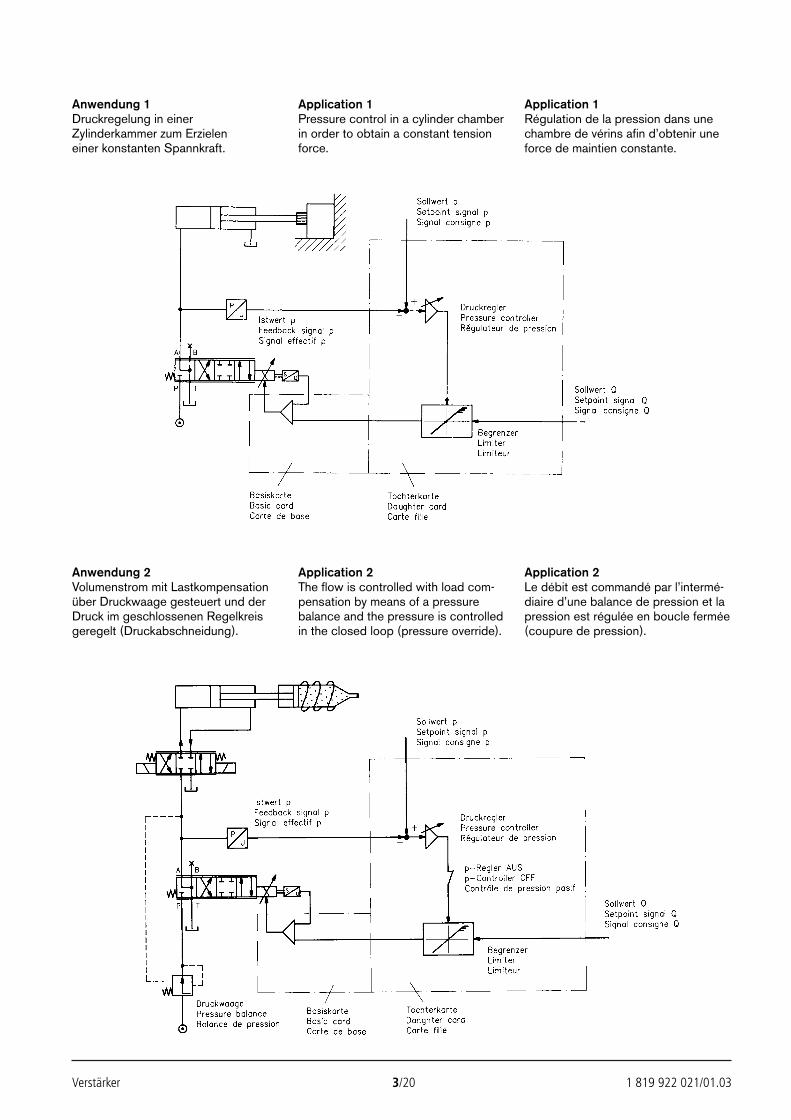
Verstärker 3/20 1 819 922 021/01.03
Anwendung 1Druckregelung in einerZylinderkammer zum Erzielen einer konstanten Spannkraft.
Application 1Pressure control in a cylinder chamberin order to obtain a constant tensionforce.
Application 1Régulation de la pression dans unechambre de vérins afin d’obtenir uneforce de maintien constante.
Anwendung 2Volumenstrom mit Lastkompensationüber Druckwaage gesteuert und derDruck im geschlossenen Regelkreisgeregelt (Druckabschneidung).
Application 2The flow is controlled with load com-pensation by means of a pressurebalance and the pressure is controlledin the closed loop (pressure override).
Application 2Le débit est commandé par l’intermé-diaire d’une balance de pression et lapression est régulée en boucle fermée(coupure de pression).
24351_4027_001-020 13.02.2003 13:53 Uhr Seite 3
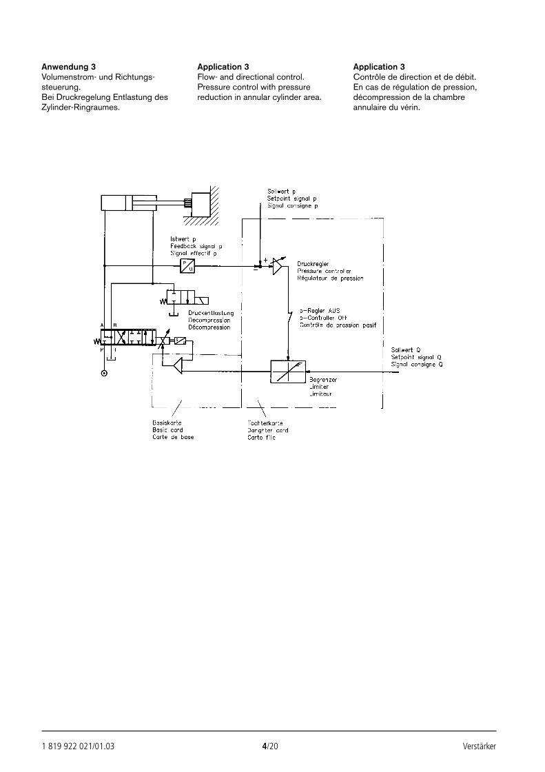
1 819 922 021/01.03 4/20 Verstärker
Anwendung 3Volumenstrom- und Richtungs-steuerung.Bei Druckregelung Entlastung desZylinder-Ringraumes.
Application 3Flow- and directional control.Pressure control with pressurereduction in annular cylinder area.
Application 3Contrôle de direction et de débit.En cas de régulation de pression,décompression de la chambreannulaire du vérin.
24351_4027_001-020 13.02.2003 13:53 Uhr Seite 4
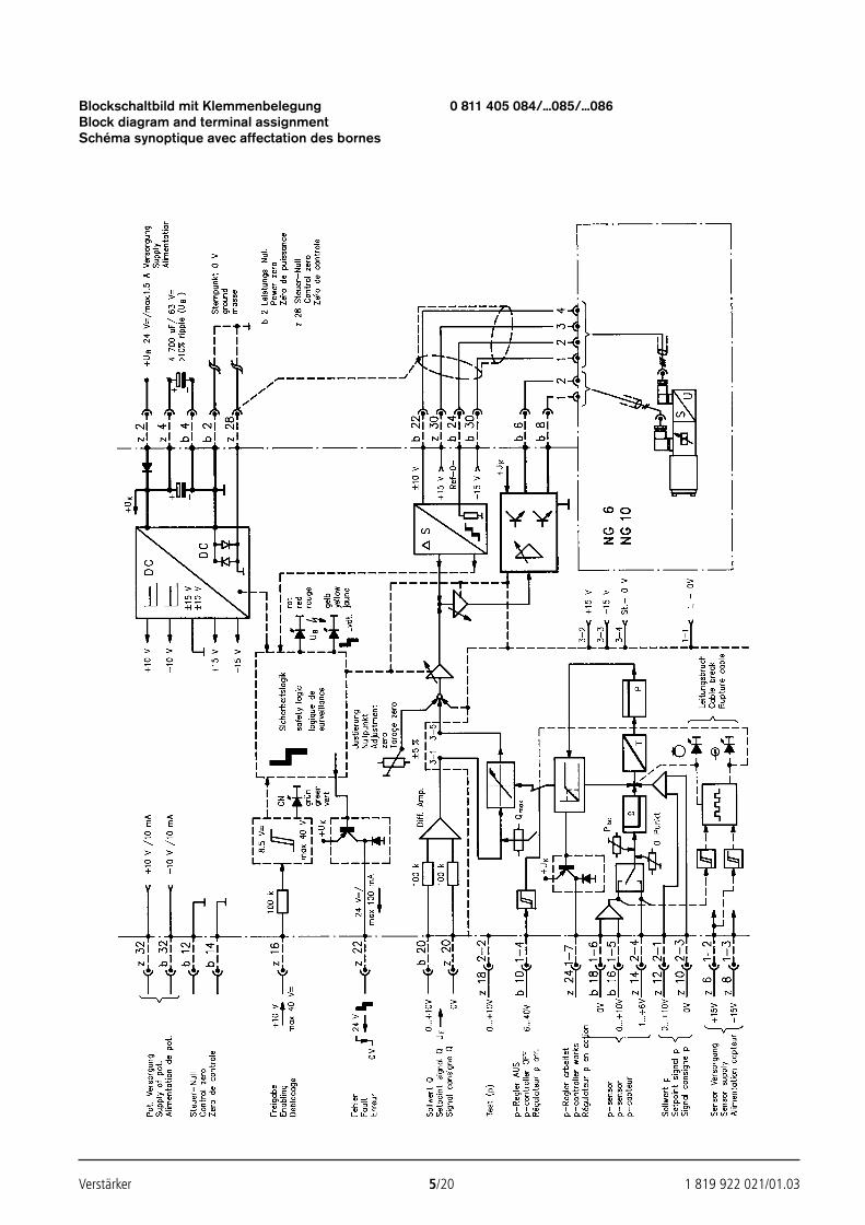
Verstärker 5/20 1 819 922 021/01.03
Blockschaltbild mit Klemmenbelegung 0 811 405 084/...085/...086Block diagram and terminal assignmentSchéma synoptique avec affectation des bornes
24351_4027_001-020 13.02.2003 13:53 Uhr Seite 5
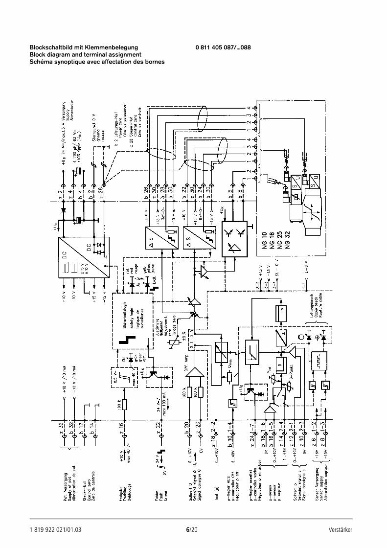
1 819 922 021/01.03 6/20 Verstärker
Blockschaltbild mit Klemmenbelegung 0 811 405 087/...088Block diagram and terminal assignmentSchéma synoptique avec affectation des bornes
24351_4027_001-020 13.02.2003 13:53 Uhr Seite 6
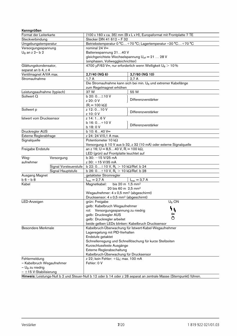
Verstärker 7/20 1 819 922 021/01.03
KenngrößenFormat der Leiterkarte (100 x 160 x ca. 35) mm (B x L x H), Europaformat mit Frontplatte 7 TESteckverbindung Stecker DIN 41 612 – F 32Umgebungstemperatur Betriebstemperatur 0 °C…70 °C; Lagertemperatur –20 °C…70 °CVersorgungsspannung nominal 24 V=UB an z 2– b 2 Batteriespannung 21…40 V
gleichgerichtete Wechselspannung Ueff = 21 … 28 V(einphasen, Vollweggleichrichter)
Glättungskondensator, 4700 µF/63 V=, nur erforderlich wenn Welligkeit UB 10 %separat an b 4, z 4Ventilmagnet A/VA max. 2,7/40 (NG 6) 3,7/60 (NG 10)Stromaufnahme 1,7 A 2,7 A
Die Stromaufnahme kann sich bei min. UB und extremer Kabellänge zum Regelmagnet erhöhen
Leistungsaufnahme (typisch) 37 W 55 WSollwert Q b 20: 0…10 V
z 20: 0 V Differenzverstärker
(Ri = 100 kΩ)Sollwert p z 12: 0…10 V
z 10: 0 V Differenzverstärker
Istwert vom Drucksensor z 14: 1…6 Vb 16: 0…10 Vb 18: 0 V Differenzverstärker
Druckregler AUS b 10: 6…40 V=Externe Reglerabfrage z 24: 24 V/0,1 A max.Signalquelle Potentiometer 10 kΩ
Versorgung ± 10 V aus b 32, z 32 (10 mA) oder externe SignalquelleFreigabe Endstufe an z 16; U = 8,5…40 V, Ri = 100 kΩ,
LED (grün) auf Frontplatte leuchtet aufWeg- Versorgung b 30: 15 V/25 mAaufnehmer z 30: 15 V/35 mA
Signal Vorsteuerstufe b 22: 0…10 V, RL 10 kΩ/Ref. b 24Signal Hauptstufe b 26: 0…10 V, RL 10 kΩ/Ref. b 28
Ausgang Magnet getakteter Stromreglerb 6 – b 8 Imax. = 2,7 A Imax. = 3,7 AKabel Magnetkabel: 20 bis 20 m 1,5 mm2
Magnetkabel: 20 bis 60 m 2,5 mm2
Wegaufnehmer: 4 x 0,5 mm2 (abgeschirmt)Drucksensor: 4 x 0,5 mm2 (abgeschirmt)
LED-Anzeigen grün: Freigabe UB ONgelb: Kabelbruch Wegaufnehmerrot: Versorgungsspannung zu niedriggelb: Druckregler AUSgelb: Druckregler arbeitetbeide gelben LEDs blinken: Kabelbruch Drucksensor
Besondere Merkmale Kabelbruch-Überwachung für Istwert-Kabel-WegaufnehmerLageregelung mit PID-VerhaltenEndstufe getaktetSchnellerregung und Schnelllöschung für kurze StellzeitenKurzschlussfeste AusgängeExterne ReglerabschaltungKabelbruch-Überwachung für Drucksensor
Fehlermeldung z 22; kein Fehler: UK; max. 100 mA– Kabelbruch Wegaufnehmer Fehler: 0 V– UB zu niedrig– 15 V-StabilisierungHinweis: Leistungs-Null b 2 und Steuer-Null b 12 oder b 14 oder z 28 separat an zentrale Masse (Sternpunkt) führen.
24351_4027_001-020 13.02.2003 13:53 Uhr Seite 7
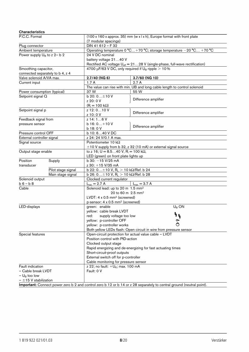
1 819 922 021/01.03 8/20 Verstärker
CharacteristicsP.C.C. Format (100 x 160 x approx. 35) mm (w x l x h), Europe format with front plate
(7 modular spacings)Plug connector DIN 41 612 – F 32Ambient temperature Operating temperature 0 °C…70 °C; storage temperature 20 °C… 70 °CPower supply UB to z 2– b 2 24 V DC nominal
battery voltage 21…40 VRectified AC voltage Ueff = 21…28 V (single-phase, full-wave rectification)
Smoothing capacitor, 4700 µF/63 V DC, only required if UB ripple 10 %connected separately to b 4, z 4Valve solenoid A/VA max. 2.7/40 (NG 6) 3.7/60 (NG 10)Current input 1.7 A 2.7 A
The value can rise with min. UB and long cable length to control solenoidPower consumption (typical) 37 W 55 WSetpoint signal Q b 20: 0…10 V
z 20: 0 V Difference amplifier
(Ri = 100 kΩ)Setpoint signal p z 12: 0…10 V
z 10: 0 V Difference amplifier
Feedback signal from z 14: 1…6 Vpressure sensor b 16: 0…10 V
b 18: 0 V Difference amplifier
Pressure control OFF b 10: 6…40 V DCExternal controller signal z 24: 24 V/0.1 A max.Signal source Potentiometer 10 kΩ
10 V supply from b 32, z 32 (10 mA) or external signal sourceOutput stage enable to z 16; U = 8.5…40 V, Ri = 100 kΩ,
LED (green) on front plate lights upPosition Supply b 30: 15 V/25 mAtransducer z 30: 15 V/35 mA
Pilot stage signal b 22: 0…10 V, RL 10 kΩ/Ref. b 24Main stage signal b 26: 0…10 V, RL 10 kΩ/Ref. b 28
Solenoid output Clocked current regulatorb 6 – b 8 Imax. = 2.7 A Imax. = 3.7 ACable Solenoid lead: up to 20 m 1.5 mm2
Solenoid lead: 20 to 60 m 2.5 mm2
LVDT: 4 x 0.5 mm2 (screened)p-sensor: 4 x 0.5 mm2 (screened)
LED-displays green: enable UB ONyellow: cable break LVDTred: supply voltage too lowyellow: p-controller OFFyellow: p-controller worksBoth yellow LEDs flash: Open circuit in wire from pressure sensor
Special features Open-circuit protection for actual value cable – LVDTPosition control with PID-actionClocked output stageRapid energizing and de-energizing for fast actuating timesShort-circuit-proof outputsExternal switch off for p-controllerCable monitoring for pressure sensor
Fault indication z 22; no fault: UK; max. 100 mA– Cable break LVDT Fault: 0 V– UB too low– 15 V stabilizationImportant: Connect power zero b 2 and control zero b 12 or b 14 or z 28 separately to central ground (neutral point).
24351_4027_001-020 13.02.2003 13:53 Uhr Seite 8
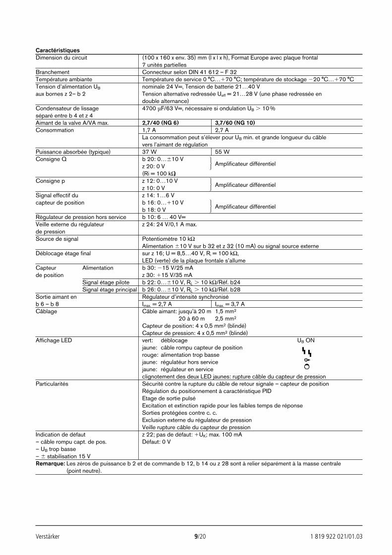
Verstärker 9/20 1 819 922 021/01.03
CaractéristiquesDimension du circuit (100 x 160 x env. 35) mm (l x l x h), Format Europe avec plaque frontal
7 unités partiellesBranchement Connecteur selon DIN 41 612 – F 32Température ambiante Température de service 0 °C…70 °C; température de stockage 20 °C…70 °CTension d’alimentation UB nominale 24 V=, Tension de batterie 21…40 Vaux bornes z 2– b 2 Tension alternative redressée Ueff = 21…28 V (une phase redressée en
double alternance)Condensateur de lissage 4700 µF/63 V=, nécessaire si ondulation UB 10 %séparé entre b 4 et z 4Aimant de la valve A/VA max. 2,7/40 (NG 6) 3,7/60 (NG 10)Consommation 1,7 A 2,7 A
La consommation peut s’élever pour UB min. et grande longueur du câble vers l’aimant de régulation
Puissance absorbée (typique) 37 W 55 WConsigne Q b 20: 0…10 V
z 20: 0 V Amplificateur différentiel
(Ri = 100 kΩ)Consigne p z 12: 0…10 V
z 10: 0 V Amplificateur différentiel
Signal effectif du z 14: 1…6 Vcapteur de position b 16: 0…10 V
b 18: 0 V Amplificateur différentiel
Règulateur de pression hors service b 10: 6 … 40 V=Veille externe du régulateur z 24: 24 V/0,1 A max.de pressionSource de signal Potentiomètre 10 kΩ
Alimentation 10 V sur b 32 et z 32 (10 mA) ou signal source externeDéblocage étage final sur z 16; U = 8,5…40 V, Ri = 100 kΩ,
LED (verte) de la plaque frontale s’allumeCapteur Alimentation b 30: 15 V/25 mAde position z 30: 15 V/35 mA
Signal étage pilote b 22: 0…10 V, RL 10 kΩ/Réf. b24Signal étage principal b 26: 0…10 V, RL 10 kΩ/Réf. b28
Sortie aimant en Régulateur d’intensité synchroniséb 6 – b 8 Imax. = 2,7 A Imax. = 3,7 ACâblage Câble aimant: jusqu’à 20 m 1,5 mm2
Câble aimant: 20 à 60 m 2,5 mm2
Capteur de position: 4 x 0,5 mm2 (blindé)Capteur de pression: 4 x 0,5 mm2 (blindé)
Affichage LED vert: déblocage UB ONjaune: câble rompu capteur de positionrouge: alimentation trop bassejaune: régulatéur hors servicejaune: régulateur en serviceclignotement des deux LED jaunes: rupture câble du capteur de pression
Particularités Sécurité contre la rupture du câble de retour signale – capteur de positionRégulation du positionnement à caractéristique PIDEtage de sortie pulséExcitation et extinction rapide pour les faibles temps de réponseSorties protégées contre c. c.Exclusion externe du régulateur de pressionVeille rupture câble du capteur de pression
Indication de défaut z 22; pas de défaut: UK; max. 100 mA– câble rompu capt. de pos. Défaut: 0 V– UB trop basse– stabilisation 15 V Remarque: Les zéros de puissance b 2 et de commande b 12, b 14 ou z 28 sont à relier séparément à la masse centrale
(point neutre).
24351_4027_001-020 13.02.2003 13:53 Uhr Seite 9
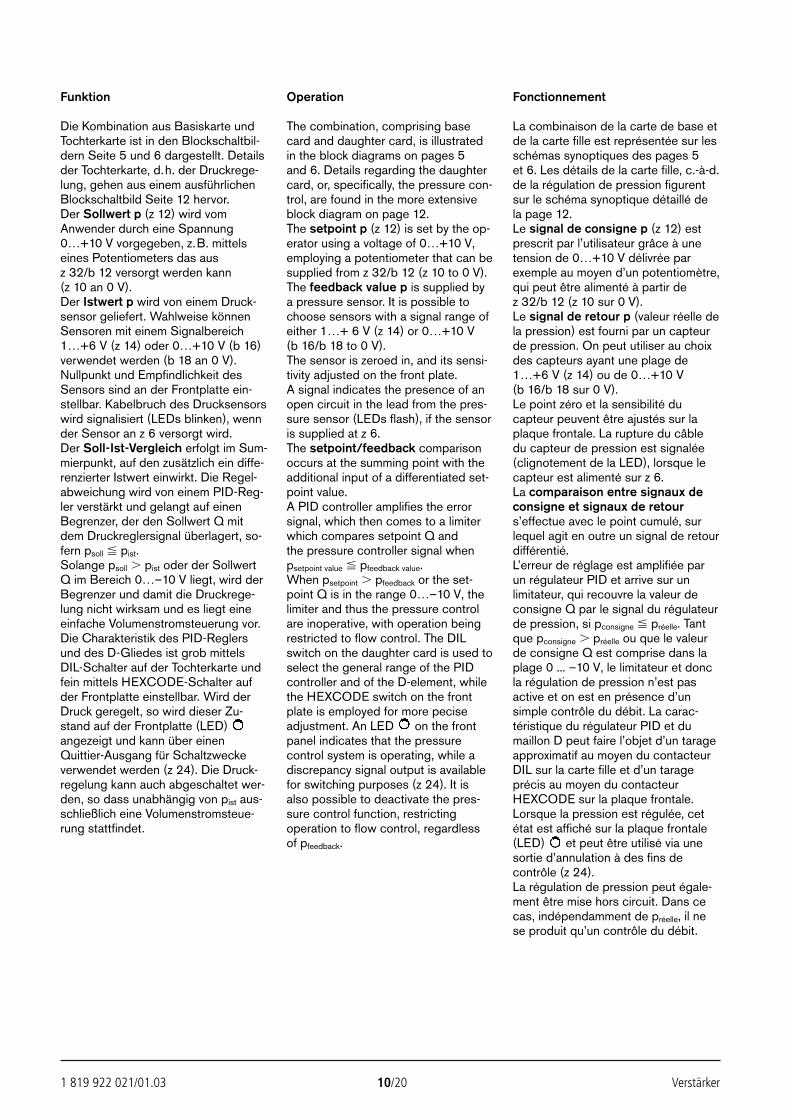
1 819 922 021/01.03 10/20 Verstärker
Funktion
Die Kombination aus Basiskarte undTochterkarte ist in den Blockschaltbil-dern Seite 5 und 6 dargestellt. Detailsder Tochterkarte, d.h. der Druckrege-lung, gehen aus einem ausführlichenBlockschaltbild Seite 12 hervor.Der Sollwert p (z 12) wird vomAnwender durch eine Spannung0…+10 V vorgegeben, z.B. mittelseines Potentiometers das aus z 32/b 12 versorgt werden kann (z 10 an 0 V).Der Istwert p wird von einem Druck-sensor geliefert. Wahlweise könnenSensoren mit einem Signalbereich1…+6 V (z 14) oder 0…+10 V (b 16)verwendet werden (b 18 an 0 V).Nullpunkt und Empfindlichkeit desSensors sind an der Frontplatte ein-stellbar. Kabelbruch des Drucksensorswird signalisiert (LEDs blinken), wennder Sensor an z 6 versorgt wird.Der Soll-Ist-Vergleich erfolgt im Sum-mierpunkt, auf den zusätzlich ein diffe-renzierter Istwert einwirkt. Die Regel-abweichung wird von einem PID-Reg-ler verstärkt und gelangt auf einenBegrenzer, der den Sollwert Q mitdem Druckreglersignal überlagert, so-fern psoll pist.Solange psoll pist oder der SollwertQ im Bereich 0…–10 V liegt, wird derBegrenzer und damit die Druckrege-lung nicht wirksam und es liegt eineeinfache Volumenstromsteuerung vor.Die Charakteristik des PID-Reglersund des D-Gliedes ist grob mittelsDIL-Schalter auf der Tochterkarte undfein mittels HEXCODE-Schalter aufder Frontplatte einstellbar. Wird derDruck geregelt, so wird dieser Zu-stand auf der Frontplatte (LED)angezeigt und kann über einenQuittier-Ausgang für Schaltzweckeverwendet werden (z 24). Die Druck-regelung kann auch abgeschaltet wer-den, so dass unabhängig von pist aus-schließlich eine Volumenstromsteue-rung stattfindet.
Operation
The combination, comprising basecard and daughter card, is illustratedin the block diagrams on pages 5 and 6. Details regarding the daughtercard, or, specifically, the pressure con-trol, are found in the more extensiveblock diagram on page 12.The setpoint p (z 12) is set by the op-erator using a voltage of 0…+10 V,employing a potentiometer that can besupplied from z 32/b 12 (z 10 to 0 V).The feedback value p is supplied bya pressure sensor. It is possible tochoose sensors with a signal range ofeither 1…+ 6 V (z 14) or 0…+10 V (b 16/b 18 to 0 V).The sensor is zeroed in, and its sensi-tivity adjusted on the front plate.A signal indicates the presence of anopen circuit in the lead from the pres-sure sensor (LEDs flash), if the sensoris supplied at z 6.The setpoint/feedback comparisonoccurs at the summing point with theadditional input of a differentiated set-point value.A PID controller amplifies the errorsignal, which then comes to a limiterwhich compares setpoint Q andthe pressure controller signal whenpsetpoint value pfeedback value.When psetpoint pfeedback or the set-point Q is in the range 0…–10 V, thelimiter and thus the pressure controlare inoperative, with operation beingrestricted to flow control. The DILswitch on the daughter card is used toselect the general range of the PIDcontroller and of the D-element, whilethe HEXCODE switch on the frontplate is employed for more peciseadjustment. An LED on the frontpanel indicates that the pressurecontrol system is operating, while adiscrepancy signal output is availablefor switching purposes (z 24). It isalso possible to deactivate the pres-sure control function, restrictingoperation to flow control, regardless of pfeedback.
Fonctionnement
La combinaison de la carte de base etde la carte fille est représentée sur lesschémas synoptiques des pages 5 et 6. Les détails de la carte fille, c.-à-d.de la régulation de pression figurentsur le schéma synoptique détaillé dela page 12.Le signal de consigne p (z 12) estprescrit par l’utilisateur grâce à unetension de 0…+10 V délivrée parexemple au moyen d’un potentiomètre,qui peut être alimenté à partir de z 32/b 12 (z 10 sur 0 V).Le signal de retour p (valeur réelle dela pression) est fourni par un capteurde pression. On peut utiliser au choixdes capteurs ayant une plage de1…+6 V (z 14) ou de 0…+10 V (b 16/b 18 sur 0 V).Le point zéro et la sensibilité ducapteur peuvent être ajustés sur laplaque frontale. La rupture du câbledu capteur de pression est signalée(clignotement de la LED), lorsque lecapteur est alimenté sur z 6.La comparaison entre signaux deconsigne et signaux de retours’effectue avec le point cumulé, surlequel agit en outre un signal de retourdifférentié.L’erreur de réglage est amplifiée parun régulateur PID et arrive sur unlimitateur, qui recouvre la valeur deconsigne Q par le signal du régulateurde pression, si pconsigne préelle. Tantque pconsigne préelle ou que le valeurde consigne Q est comprise dans laplage 0 ... –10 V, le limitateur et doncla régulation de pression n’est pasactive et on est en présence d’unsimple contrôle du débit. La carac-téristique du régulateur PID et dumaillon D peut faire l’objet d’un tarageapproximatif au moyen du contacteurDIL sur la carte fille et d’un tarageprécis au moyen du contacteurHEXCODE sur la plaque frontale.Lorsque la pression est régulée, cetétat est affiché sur la plaque frontale(LED) et peut être utilisé via unesortie d’annulation à des fins decontrôle (z 24).La régulation de pression peut égale-ment être mise hors circuit. Dans cecas, indépendamment de préelle, il nese produit qu’un contrôle du débit.
24351_4027_001-020 13.02.2003 13:53 Uhr Seite 10
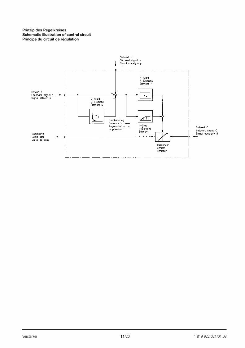
Verstärker 11/20 1 819 922 021/01.03
Prinzip des RegelkreisesSchematic illustration of control circuitPrincipe du circuit de régulation
24351_4027_001-020 13.02.2003 13:53 Uhr Seite 11
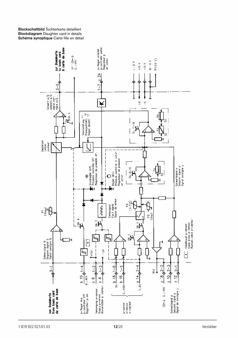
1 819 922 021/01.03 12/20 Verstärker
Blockschaltbild Tochterkarte detailliertBlockdiagram Daughter card in detailsSchéma synoptique Carte fille en détail
24351_4027_001-020 13.02.2003 13:53 Uhr Seite 12
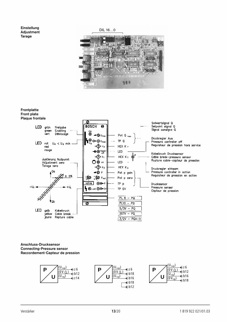
Verstärker 13/20 1 819 922 021/01.03
EinstellungAdjustmentTarage
FrontplatteFront platePlaque frontale
Anschluss-DrucksensorConnecting-Pressure sensorRaccordement-Capteur de pression
DIL 16…0
(Usup)PU
z6(0V/ ) b12(Usig) z14
(Usup)PU
z6(0V/ ) b18(Usig) b16
b18b12
(Usup)
PU
z6(0V/ ) b12(Usig) b16(0Vsig)
b18
24351_4027_001-020 13.02.2003 13:53 Uhr Seite 13
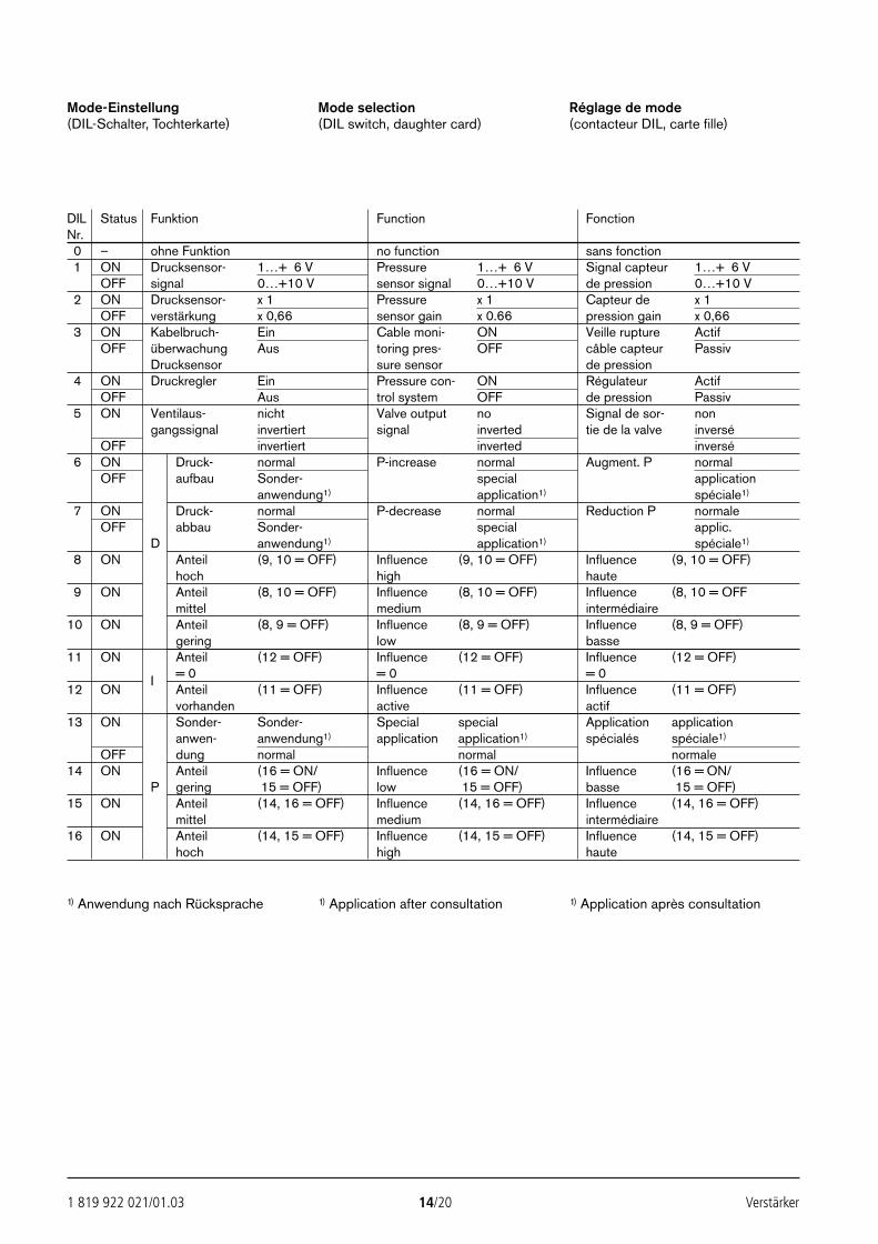
1 819 922 021/01.03 14/20 Verstärker
Mode-Einstellung(DIL-Schalter, Tochterkarte)
Mode selection(DIL switch, daughter card)
Réglage de mode(contacteur DIL, carte fille)
DIL Status Funktion Function FonctionNr.0 – ohne Funktion no function sans fonction1 ON Drucksensor- 1…+ 6 V Pressure 1…+ 6 V Signal capteur 1…+ 6 V
OFF signal 0…+10 V sensor signal 0…+10 V de pression 0…+10 V2 ON Drucksensor- x 1 Pressure x 1 Capteur de x 1
OFF verstärkung x 0,66 sensor gain x 0.66 pression gain x 0,663 ON Kabelbruch- Ein Cable moni- ON Veille rupture Actif
OFF überwachung Aus toring pres- OFF câble capteur PassivDrucksensor sure sensor de pression
4 ON Druckregler Ein Pressure con- ON Régulateur ActifOFF Aus trol system OFF de pression Passiv
5 ON Ventilaus- nicht Valve output no Signal de sor- nongangssignal invertiert signal inverted tie de la valve inversé
OFF invertiert inverted inversé6 ON Druck- normal P-increase normal Augment. P normal
OFF aufbau Sonder- special applicationanwendung1) application1) spéciale1)
7 ON Druck- normal P-decrease normal Reduction P normaleOFF abbau Sonder- special applic.
D anwendung1) application1) spéciale1)
8 ON Anteil (9, 10 = OFF) Influence (9, 10 = OFF) Influence (9, 10 = OFF)hoch high haute
9 ON Anteil (8, 10 = OFF) Influence (8, 10 = OFF) Influence (8, 10 = OFFmittel medium intermédiaire
10 ON Anteil (8, 9 = OFF) Influence (8, 9 = OFF) Influence (8, 9 = OFF)gering low basse
11 ON Anteil (12 = OFF) Influence (12 = OFF) Influence (12 = OFF)
I = 0 = 0 = 012 ON Anteil (11 = OFF) Influence (11 = OFF) Influence (11 = OFF)
vorhanden active actif13 ON Sonder- Sonder- Special special Application application
anwen- anwendung1) application application1) spécialés spéciale1)
OFF dung normal normal normale14 ON Anteil (16 = ON/ Influence (16 = ON/ Influence (16 = ON/
P gering 15 = OFF) low 15 = OFF) basse 15 = OFF)15 ON Anteil (14, 16 = OFF) Influence (14, 16 = OFF) Influence (14, 16 = OFF)
mittel medium intermédiaire16 ON Anteil (14, 15 = OFF) Influence (14, 15 = OFF) Influence (14, 15 = OFF)
hoch high haute
1) Anwendung nach Rücksprache 1) Application after consultation 1) Application après consultation
24351_4027_001-020 13.02.2003 13:53 Uhr Seite 14
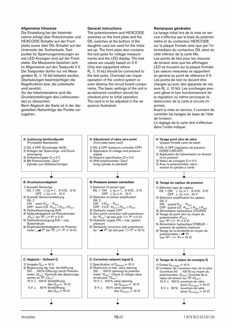
Verstärker 15/20 1 819 922 021/01.03
Allgemeine HinweiseDie Einstellung bei der Inbetrieb-nahme erfolgt über Potentiometer undHEXCODE-Schalter auf der Front-platte sowie über DIL-Schalter auf derUnterseite der Tochterkarte. Test-punkte für Spannungsmessungen so-wie LED-Anzeigen sind auf der Front-platte. Die Messwerte beziehen sichim Allgemeinen auf den Testpunkt 0 V.Die Testpunkte dürfen nur mit Mess-geräten RL 10 kΩ belastet werden.Überlastungen beeinträchtigen dieRegelfunktion bzw. die Leiterkartewird zerstört.Vor der Inbetriebnahme sind dieGrundeinstellungen des Lieferzustan-des zu überprüfen.Beim Abgleich der Karte ist in der dar-gestellten Reihenfolge der Punkte vor-zugehen:
General instructionsThe potentiometers and HEXCODEswitches on the front plate and theDIL switches at the bottom of thedaughter card are used for the initialset-up. The front plate also containsthe test jacks for voltage measure-ments and the LED display. The testvalues are usually based on 0 V.Only test equipment where RL 10 kΩ should be connected tothe test jacks. Overload can impairoperation of the control system oreven destroy the circuit board compo-nents. The basic settings of the unit inas-delivered condition should bechecked prior to initial operation.The card is to be adjusted in the se-quence illustrated:
Remarques généralesLe tarage initial lors de la mise en ser-vice s’effectue par le biais du potentio-mètre et du contacteur HEXCODEsur la plaque frontale ainsi que par l’in-termédiaire du contacteur DIL situé ducôté inférieur de la carte fille.Les points de test pour les mesuresde tension ainsi que les affichagesLED se trouvent sur la plaque frontale.Les valeurs mesurées se rapportenten général au point de référence 0 V.Les points de test ne doivent êtrechargés qu’avec des appareils de me-sure RL 10 kΩ. Les surcharges peu-vent gêner le bon fonctionnement dela régulation ou même provoquer ladestruction de la carte à circuits im-primés.Avant la mise en service, il convient decontrôler les tarages de base de l’étatde livraison.Le réglage de la carte doit s’effectuerdans l’ordre indiqué:
A: Tarage point zéro de valve(plaque frontale carte de base)
1) DIL 4 OFF (régulateur de pressionHORS CIRCUIT)
2) Application de l’alimentation en tensionet en pression
3) Valeur de consigne Q = 0 V4) Avec le potentiomètre «zéro»
amener le cylindre à l’arrêt
A: Adjustment of valve zero-point(front plate base card)
1) DIL 4 OFF (pressure controller OFF)2) Application of voltage and pressure
supply3) Setpoint specification Q = 0 V4) With potentiometer “Zero”
bring cylinder to standstill
A: Justierung Ventilnullpunkt(Frontplatte Basiskarte)
1) DIL 4 OFF (Druckregler AUS)2) Anlegen der Spannungs- und Druck-
versorgung3) Sollwertvorgabe Q = 0 V4) Mit Potentiometer „Zero“
Zylinder zum Stillstand bringen
C: Abgleich – Sollwert Q
1) Vorgabe Qsoll = 10 V2) Begrenzung der max. Ventilöffnung
(50 … 100 %-Öffnung) durch Potentio-meter „Qmax“. Kontrolle des Spannungs-wertes an TP „Qmax“:10 V 100 % Ventilöffnung
(bei Qsoll = 10 V)5 V 50 % Ventilöffnung
(bei Qsoll = 10 V)
C: Correction setpoint signal Q
1) Specification of Qsetpoint = 10 V2) Restriction of max. valve opening
(50 … 100 % opening) by potentio-meter “Qmax”. Check of voltage valueat test jack “Qmax”:10 V 100 % valve opening
(at Qsetpoint = 10 V)5 V 50 % valve opening
(bei Qsetpoint = 10 V)
C: Tarage de la valeur de consigne Q
1) Entrée Qconsigne = 10 V2) Limitation de l’ouverture max. de la valve
(ouverture 50 … 100 %) au moyen dupotentiomètre «Qmax». Contrôle de lavaleur de tension sur TP «Qmax»:10 V 100 % ouverture de valve
(pour Qconsigne = 10 V)5 V 50 % ouverture de valve
(pour Qconsigne = 10 V)
B: Drucksensorabgleich
1) Auswahl SensortypDIL 1 ON UA = 1…6 V/(0…5 V)
OFF UA = 0…10 V2) Auswahl Sensorverstärkung
DIL 2ON wenn PSys PNomOFF: wenn 0,5 · PNom ≤ PSys ≤ PNom
3) Hydraulikversorgung AUS4) Nullpunktabgleich mit Potentiometer
„PNull“ (an TP „ P“ = 0 V)5) Hydraulikversorgung EIN – max.
Systemdruck6) Empfindlichkeitsabgleich mit Potentio-
meter „ P“ (an TP „ P“ = 10 V)
B: Pressure sensor correction
1) Selection of sensor typeDIL 1 ON UA = 1…6 V/(0…5 V)
OFF UA = 0…10 V2) Selection of sensor amplification
DIL 2ON if PSys PNomOFF: if 0.5 · PNom ≤ PSys ≤ PNom
3) Hydraulic supply OFF4) Zero-point correction with potentiome-
ter “Pzero” (at test jack “ P” = 0 V)5) Hydraulic supply ON – max. system
pressure6) Sensitivity correction with potentiome-
ter “ P” (at test jack “ P” = 10 V)
B: Tarage du capteur de pression
1) Sélection type de capteurDIL 1 ON UA = 1…6 V/(0…5 V)
OFF UA = 0…10 V2) Sélection amplification du capteur
DIL 2ON quand PSys PNomOFF: quand 0,5 · PNom ≤ PSys ≤ PNom
3) Alimentation hydraulique COUPEE4) Tarage du point zéro au moyen du
potentiomètre «Pzéro»(sur TP « P» = 0 V)
5) Alimentation hydraulique ETABLIE –pression de système maximum
6) Tarage de la sensibilité au moyen dupotentiomètre « P» (sur TP « P» = 10 V)
24351_4027_001-020 13.02.2003 13:53 Uhr Seite 15
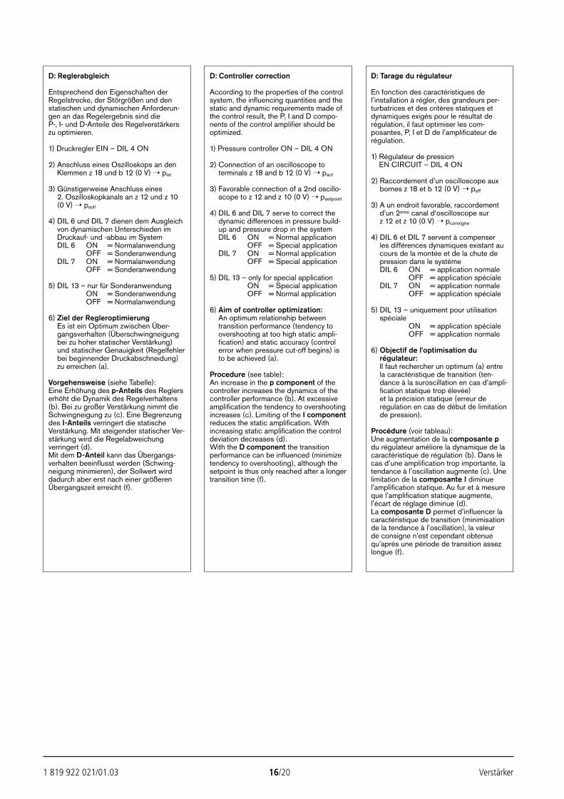
1 819 922 021/01.03 16/20 Verstärker
D: Tarage du régulateur
En fonction des caractéristiques del’installation à régler, des grandeurs per-turbatrices et des critères statiques etdynamiques exigés pour le résultat derégulation, il faut optimiser les com-posantes, P, I et D de l’amplificateur derégulation.
1) Régulateur de pressionEN CIRCUIT – DIL 4 ON
2) Raccordement d’un oscilloscope auxbornes z 18 et b 12 (0 V) peff
3) A un endroit favorable, raccordementd’un 2ème canal d’oscilloscope sur z 12 et z 10 (0 V) pconsigne
4) DIL 6 et DIL 7 servent à compenser les différences dynamiques existant aucours de la montée et de la chute depression dans le systèmeDIL 6 ON = application normale
OFF = application spécialeDIL 7 ON = application normale
OFF = application spéciale
5) DIL 13 – uniquement pour utilisationspéciale
ON = application spécialeOFF = application normale
6) Objectif de l’optimisation durégulateur:Il faut rechercher un optimum (a) entrela caractéristique de transition (ten-dance à la suroscillation en cas d’ampli-fication statique trop élevée) et la précision statique (erreur derégulation en cas de début de limitationde pression).
Procédure (voir tableau):Une augmentation de la composante pdu régulateur améliore la dynamique de lacaractéristique de régulation (b). Dans lecas d’une amplification trop importante, latendance à l’oscillation augmente (c). Unelimitation de la composante I diminuel’amplification statique. Au fur et à mesureque l’amplification statique augmente,l’écart de réglage diminue (d).La composante D permet d’influencer lacaractéristique de transition (minimisationde la tendance à l’oscillation), la valeur de consigne n’est cependant obtenuequ’après une période de transition assezlongue (f).
D: Controller correction
According to the properties of the controlsystem, the influencing quantities and thestatic and dynamic requirements made ofthe control result, the P, I and D compo-nents of the control amplifier should beoptimized.
1) Pressure controller ON – DIL 4 ON
2) Connection of an oscilloscope toterminals z 18 and b 12 (0 V) pact
3) Favorable connection of a 2nd oscillo-scope to z 12 and z 10 (0 V) psetpoint
4) DIL 6 and DIL 7 serve to correct thedynamic differences in pressure build-up and pressure drop in the systemDIL 6 ON = Normal application
OFF = Special applicationDIL 7 ON = Normal application
OFF = Special application
5) DIL 13 – only for special applicationON = Special applicationOFF = Normal application
6) Aim of controller optimization:An optimum relationship betweentransition performance (tendency toovershooting at too high static ampli-fication) and static accuracy (controlerror when pressure cut-off begins) isto be achieved (a).
Procedure (see table):An increase in the p component of thecontroller increases the dynamics of thecontroller performance (b). At excessiveamplification the tendency to overshootingincreases (c). Limiting of the I componentreduces the static amplification. Withincreasing static amplification the controldeviation decreases (d).With the D component the transitionperformance can be influenced (minimizetendency to overshooting), although thesetpoint is thus only reached after a longertransition time (f).
D: Reglerabgleich
Entsprechend den Eigenschaften derRegelstrecke, der Störgrößen und denstatischen und dynamischen Anforderun-gen an das Regelergebnis sind dieP-, I- und D-Anteile des Regelverstärkerszu optimieren.
1) Druckregler EIN – DIL 4 ON
2) Anschluss eines Oszilloskops an denKlemmen z 18 und b 12 (0 V) pist
3) Günstigerweise Anschluss eines2. Oszilloskopkanals an z 12 und z 10(0 V) psoll
4) DIL 6 und DIL 7 dienen dem Ausgleichvon dynamischen Unterschieden imDruckauf- und -abbau im SystemDIL 6 ON = Normalanwendung
OFF = SonderanwendungDIL 7 ON = Normalanwendung
OFF = Sonderanwendung
5) DIL 13 – nur für SonderanwendungON = SonderanwendungOFF = Normalanwendung
6) Ziel der RegleroptimierungEs ist ein Optimum zwischen Über-gangsverhalten (Überschwingneigungbei zu hoher statischer Verstärkung)und statischer Genauigkeit (Regelfehlerbei beginnender Druckabschneidung)zu erreichen (a).
Vorgehensweise (siehe Tabelle):Eine Erhöhung des p-Anteils des Reglerserhöht die Dynamik des Regelverhaltens(b). Bei zu großer Verstärkung nimmt dieSchwingneigung zu (c). Eine Begrenzungdes I-Anteils verringert die statischeVerstärkung. Mit steigender statischer Ver-stärkung wird die Regelabweichungverringert (d).Mit dem D-Anteil kann das Übergangs-verhalten beeinflusst werden (Schwing-neigung minimieren), der Sollwert wirddadurch aber erst nach einer größerenÜbergangszeit erreicht (f).
24351_4027_001-020 13.02.2003 13:53 Uhr Seite 16
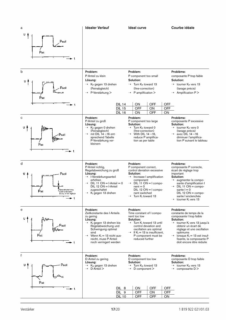
Verstärker 17/20 1 819 922 021/01.03
Idealer Verlauf Ideal curve Courbe idéale
Problem:P-Anteil zu kleinLösung: KP gegen 13 drehen
(Feinabgleich) P-Verstärkung >
Problem:P component too smallSolution: Turn KP toward 13
(fine-correction) P amplification >
Problème:composante P trop faibleSolution: tourner KP vers 13
(tarage précis) Amplification P >
Problem:P-Anteil zu großLösung: KP gegen 0 drehen
(Feinabgleich) mit DIL 14 –16 ent-
sprechend TabelleP-Verstärkung ver-kleinern
Problem:P component too largeSolution: Turn KP toward 0
(fine-correction) With DIL 14 –16,
reduce P amplifica-tion as per table
Problème:composante P excessiveSolution: tourner KP vers 0
(tarage précis) avec DIL 14 –16
diminuer l’amplifica-tion P suivant le tableau
Problem:P-Anteil richtig,Regelabweichung zu großLösung: I-Verstärkungsanteil
erhöhen DIL 11 ON = I-Anteil = 0
DIL 12 ON = I-Anteilzugeschaltet
KI gegen 13 drehen
Problem:P component correct,control deviation excessiveSolution: Increase I amplification
component DIL 11 ON = I compo-
nent = 0DIL 12 ON = I compo-nent switched
Turn KI toward 13
Problème:composante P correcte,écart de réglage tropimportantSolution: augmenter la compo-
sante d’amplification I DIL 11 ON = compo-
sante I = 0DIL 12 ON = compo-sante I enclenchés
tourner KI vers 13
Problem:Zeitkonstante des I-Anteilszu geringLösung: KI gegen 13 drehen bis
Regelabweichung undSchwingung optimalsind
Wenn KI = 13 nicht aus-reicht, muss P-Anteilnoch verringert werden
Problem:Time constant of I compo-nent too lowSolution: Turn KI toward 13 until
control deviation andoscillation are optimal
If KI = 13 is insufficient,P component must bereduced further
Problème:constante de temps de lacomposante I trop faibleSolution: tourner KI vers 13 jusqu’à
obtenir un écart deréglage et une oscillationoptimums
lorsque KI = 13 est insuf-fisante, la composante Pdoit encore être réduite
Problem:D-Anteil zu geringLösung: KD gegen 13 drehen D-Anteil >
Problem:D component too lowSolution: Turn KD toward 13 D component >
Problème:composante D trop faibleSolution: tourner KD vers 13 composante D >
a
b
c
d
e
f
DIL 14 ON OFF OFFDIL 15 OFF ON OFFDIL 16 ON OFF ON
DIL 8 ON OFF OFFDIL 9 OFF ON OFFDIL 10 OFF OFF ON
24351_4027_001-020 13.02.2003 13:53 Uhr Seite 17
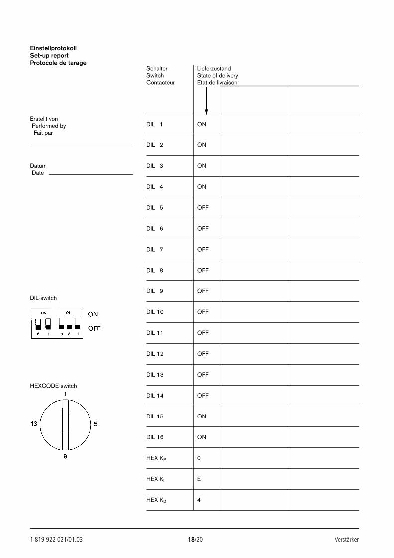
1 819 922 021/01.03 18/20 Verstärker
EinstellprotokollSet-up reportProtocole de tarage
Schalter LieferzustandSwitch State of deliveryContacteur Etat de livraison
Erstellt vonPerformed by DIL 1 ONFait par
DIL 2 ON
Datum DIL 3 ONDate
DIL 4 ON
DIL 5 OFF
DIL 6 OFF
DIL 7 OFF
DIL 8 OFF
DIL 9 OFFDIL-switch
DIL 10 OFF
DIL 11 OFF
DIL 12 OFF
DIL 13 OFF
HEXCODE-switch
DIL 14 OFF
DIL 15 ON
DIL 16 ON
HEX KP 0
HEX KI E
HEX KD 4
24351_4027_001-020 13.02.2003 13:53 Uhr Seite 18
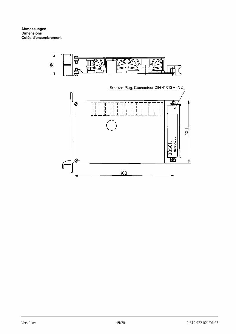
Verstärker 19/20 1 819 922 021/01.03
AbmessungenDimensionsCotés d’encombrement
24351_4027_001-020 13.02.2003 13:53 Uhr Seite 19

Bosch Rexroth AG Die angegebenen Daten dienen allein derIndustrial Hydraulics Produktbeschreibung. Eine Aussage über eineD-97813 Lohr am Main bestimmte Beschaffenheit oder eine Eignung fürZum Eisengießer 1 D-97816 Lohr am Main einen bestimmten Einsatzzweck kann ausTelefon 0 93 52/18-0 unseren Angaben nicht abgeleitet werden. Es istTelefax 0 93 52/18-23 58 Telex 6 89 418-0 zu beachten, dass unsere Produkte einemeMail [email protected] natürlichen Verschleiß- und AlterungsprozessInternet www.boschrexroth.de unterliegen.
1 819 922 021/01.03 20/20 Verstärker
24351_4027_001-020 13.02.2003 13:53 Uhr Seite 20
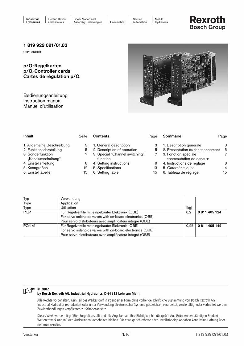
Industrial Electric Drives Linear Motion and Service MobileHydraulics and Controls Assembly Technologies Pneumatics Automation Hydraulics
1 819 929 091/01.03UBY 013/89
p/Q-Regelkartenp/Q-Controller cardsCartes de régulation p/Q
BedienungsanleitungInstruction manualManuel d’utilisation
© 2002by Bosch Rexroth AG, Industrial Hydraulics, D-97813 Lohr am Main
Alle Rechte vorbehalten. Kein Teil des Werkes darf in irgendeiner Form ohne vorherige schriftliche Zustimmung von Bosch Rexroth AG,Industrial Hydraulics reproduziert oder unter Verwendung elektronischer Systeme gespeichert, verarbeitet, vervielfältigt oder verbreitet werden.Zuwiderhandlungen verpflichten zu Schadensersatz.
Dieses Werk wurde mit größter Sorgfalt erstellt und alle Angaben auf ihre Richtigkeit hin überprüft. Aus Gründen der ständigen Produkt-Weiterentwicklung müssen Änderungen vorbehalten bleiben. Für etwaige fehlerhafte oder unvollständige Angaben kann keine Haftung über-nommen werden.
Verstärker 1/16 1 819 929 091/01.03
Typ VerwendungType ApplicationType Utilisation [kg]PQ-1 Für Regelventile mit eingebauter Elektronik (OBE) 0,2 0 811 405 124
For servo solenoids valves with on-board electronics (OBE)Pour servo-distributeurs avec amplificateur intégré (OBE)
PQ-1/2 Für Regelventile mit eingebauter Elektronik (OBE) 0,25 0 811 405 149For servo solenoids valves with on-board electronics (OBE)Pour servo-distributeurs avec amplificateur intégré (OBE)
Inhalt Seite
1. Allgemeine Beschreibung 32. Funktionsdarstellung 53. Sonderfunktion 7
„Kanalumschaltung“4. Einstellanleitung 85. Kenngrößen 126. Einstelltabelle 15
Contents Page
1. General description 32. Description of operation 53. Special “Channel switching” 7
function4. Setting instructions 85. Specifications 136. Setting table 15
Sommaire Page
1. Description générale 32. Présentation du fonctionnement 53. Fonction spéciale 7
«commutation de canaux»4. Instructions de réglage 85. Caractéristiques 146. Tableau de réglage 15
24389_4030_001-016 25.02.2003 9:21 Uhr Seite 1
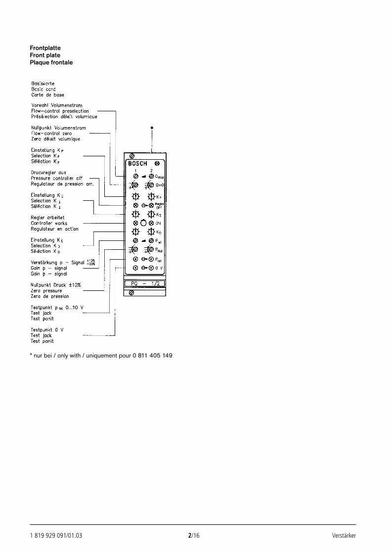
1 819 929 091/01.03 2/16 Verstärker
FrontplatteFront platePlaque frontale
* nur bei / only with / uniquement pour 0 811 405 149
24389_4030_001-016 25.02.2003 9:21 Uhr Seite 2
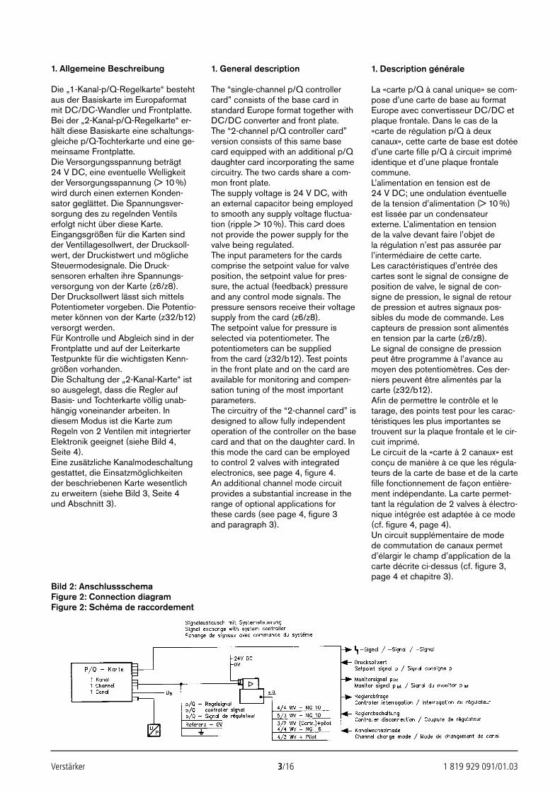
Verstärker 3/16 1 819 929 091/01.03
1. Allgemeine Beschreibung
Die „1-Kanal-p/Q-Regelkarte“ bestehtaus der Basiskarte im Europaformatmit DC/DC-Wandler und Frontplatte.Bei der „2-Kanal-p/Q-Regelkarte“ er-hält diese Basiskarte eine schaltungs-gleiche p/Q-Tochterkarte und eine ge-meinsame Frontplatte.Die Versorgungsspannung beträgt 24 V DC, eine eventuelle Welligkeitder Versorgungsspannung (> 10 %)wird durch einen externen Konden-sator geglättet. Die Spannungsver-sorgung des zu regelnden Ventilserfolgt nicht über diese Karte.Eingangsgrößen für die Karten sindder Ventillagesollwert, der Drucksoll-wert, der Druckistwert und möglicheSteuermodesignale. Die Druck-sensoren erhalten ihre Spannungs-versorgung von der Karte (z6/z8).Der Drucksollwert lässt sich mittelsPotentiometer vorgeben. Die Potentio-meter können von der Karte (z32/b12)versorgt werden.Für Kontrolle und Abgleich sind in derFrontplatte und auf der LeiterkarteTestpunkte für die wichtigsten Kenn-größen vorhanden.Die Schaltung der „2-Kanal-Karte“ istso ausgelegt, dass die Regler aufBasis- und Tochterkarte völlig unab-hängig voneinander arbeiten. Indiesem Modus ist die Karte zumRegeln von 2 Ventilen mit integrierterElektronik geeignet (siehe Bild 4,Seite 4).Eine zusätzliche Kanalmodeschaltunggestattet, die Einsatzmöglichkeiten der beschriebenen Karte wesentlichzu erweitern (siehe Bild 3, Seite 4und Abschnitt 3).
1. General description
The “single-channel p/Q controllercard” consists of the base card instandard Europe format together withDC/DC converter and front plate. The “2-channel p/Q controller card”version consists of this same basecard equipped with an additional p/Qdaughter card incorporating the samecircuitry. The two cards share a com-mon front plate.The supply voltage is 24 V DC, withan external capacitor being employedto smooth any supply voltage fluctua-tion (ripple > 10 %). This card doesnot provide the power supply for thevalve being regulated.The input parameters for the cardscomprise the setpoint value for valveposition, the setpoint value for pres-sure, the actual (feedback) pressureand any control mode signals. Thepressure sensors receive their voltagesupply from the card (z6/z8).The setpoint value for pressure isselected via potentiometer. Thepotentiometers can be suppliedfrom the card (z32/b12). Test pointsin the front plate and on the card areavailable for monitoring and compen-sation tuning of the most importantparameters.The circuitry of the “2-channel card” isdesigned to allow fully independentoperation of the controller on the basecard and that on the daughter card. Inthis mode the card can be employedto control 2 valves with integratedelectronics, see page 4, figure 4.An additional channel mode circuitprovides a substantial increase in therange of optional applications forthese cards (see page 4, figure 3and paragraph 3).
1. Description générale
La «carte p/Q à canal unique» se com-pose d’une carte de base au formatEurope avec convertisseur DC/DC etplaque frontale. Dans le cas de la «carte de régulation p/Q à deuxcanaux», cette carte de base est dotéed’une carte fille p/Q à circuit impriméidentique et d’une plaque frontalecommune.L’alimentation en tension est de 24 V DC; une ondulation éventuellede la tension d’alimentation (> 10 %)est lissée par un condensateurexterne. L’alimentation en tensionde la valve devant faire l’objet dela régulation n’est pas assurée parl’intermédiaire de cette carte.Les caractéristiques d’entrée descartes sont le signal de consigne deposition de valve, le signal de con-signe de pression, le signal de retourde pression et autres signaux pos-sibles du mode de commande. Lescapteurs de pression sont alimentésen tension par la carte (z6/z8).Le signal de consigne de pressionpeut être programme à l’avance aumoyen des potentiomètres. Ces der-niers peuvent être alimentés par lacarte (z32/b12).Afin de permettre le contrôle et letarage, des points test pour les carac-téristiques les plus importantes setrouvent sur la plaque frontale et le cir-cuit imprimé.Le circuit de la «carte à 2 canaux» estconçu de manière à ce que les régula-teurs de la carte de base et de la cartefille fonctionnement de façon entière-ment indépendante. La carte permet-tant la régulation de 2 valves à électro-nique intégrée est adaptée à ce mode(cf. figure 4, page 4).Un circuit supplémentaire de mode de commutation de canaux permetd’élargir le champ d’application de lacarte décrite ci-dessus (cf. figure 3,page 4 et chapitre 3).
Bild 2: AnschlussschemaFigure 2: Connection diagramFigure 2: Schéma de raccordement
24389_4030_001-016 25.02.2003 9:21 Uhr Seite 3
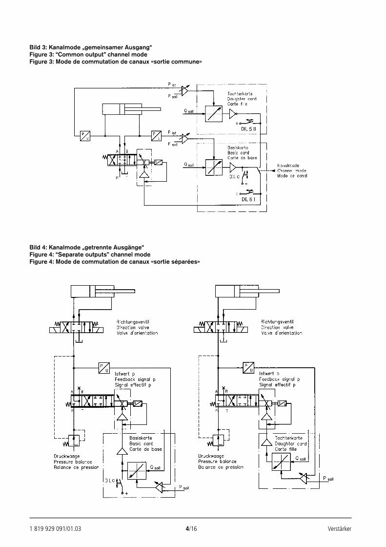
1 819 929 091/01.03 4/16 Verstärker
Bild 3: Kanalmode „gemeinsamer Ausgang“Figure 3: “Common output” channel modeFigure 3: Mode de commutation de canaux «sortie commune»
Bild 4: Kanalmode „getrennte Ausgänge“Figure 4: “Separate outputs” channel modeFigure 4: Mode de commutation de canaux «sortie séparées»
24389_4030_001-016 25.02.2003 9:21 Uhr Seite 4
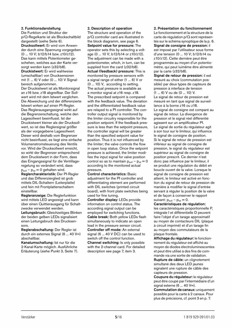
Verstärker 5/16 1 819 929 091/01.03
2. FunktionsdarstellungDie Funktion und Struktur der p/Q-Regelkarte ist als Blockschaltbilddargestellt (siehe Seite 6).Drucksollwert: Er wird vom Anwen-der durch eine Spannung vorgegeben(0 ... 10 V; b12/b14 bzw. z10/z12). Das kann mittels Potentiometer ge-schehen, welches aus der Karte ver-sorgt werden kann (z32/b8).Druckistwert: Er wird wahlweise(umschaltbar) von Drucksensoren mit (1 ... 6) V oder (0 ... 10) V Signal-bereich aufgenommen.Der Druckistwert ist als Monitorsignalan z16 bzw. z18 abgreifbar. Der Soll-wert wird mit dem Istwert verglichen.Die Abweichung und der differenzierteIstwert wirken auf einen PI-Regler.Das Reglerausgangssignal wirkt aufdie Begrenzerschaltung, welche denLagesollwert beeinflusst. Ist derDruckistwert kleiner als der Drucksoll-wert, so ist das Reglersignal größerals der vorgegebene Lagesollwert.Dieser wird deshalb vom Begrenzernicht beeinflusst, es liegt eine einfacheVolumenstromsteuerung des Ventilsvor. Wird der Drucksollwert erreicht,so wirkt der Begrenzer entsprechenddem Druckistwert in der Form, dassdas Eingangssignal für die Ventillage-regelung so verändert wird, dass psoll – pist = 0 gehalten wird.Reglercharakteristik: Der PI-Reglerund das Differenzierglied ist grobmittels DIL-Schaltern (Leiterplatte)und fein mit Frontplattenschalterneinstellbar.Regleranzeige: Die Reglerfunktionwird mittels LED angezeigt und kannüber einen Quittierausgang für Schalt-zwecke verwendet werden.Leitungsbruch: Gleichzeitiges Blinkender beiden gelben LEDs signalisierteinen Leitungsbruch des Drucksen-sors.Reglerabschaltung: Der Regler istdurch ein externes Signal (6 ... 40 V=)abschaltbar.Kanalumschaltung: Ist nur für die 2-Kanal-Karte möglich. AusführlicheErläuterung (siehe Punkt 3, Seite 7).
2. Description of operationThe structure and operation of thep/Q controller card are illustrated inthe block diagramm, see page 6.Setpoint value for pressure: Theoperator sets this by selecting a volt-age (0 ... 10 V; b12/b14 or z10/z12).The adjustment can be made with apotentiometer, which, in turn, can besupplied from the card (z32/b8).Actual (feedback) pressure: This ismonitored by pressure sensors witha signal range of either (1 ... 6) V or(0 ... 10) V, according to setting.The actual pressure is available asa monitor signal at z16 resp. z18.The prescribed setpoint is comparedwith the feedback value. The deviationand the differentiated feedback valueare relayed to a PI controller. The con-troller output signal is monitored bythe limiter circuitry responsible for theposition setpoint. If the feedback pres-sure is less than the setpoint pressure,the controller signal will be greaterthan the specified setpoint value forposition. Thus it is not influenced bythe limiter; the valve controls the flowin open loop status. Once the setpointpressure is achieved, the limiter modi-fies the input signal for valve positioncontrol so as to maintain psoll – pist = 0according to the monitored actualpressure.Control characteristics: Basicadjustment for the PI controller anddifferentiating element are performedwith DIL switches (printed circuitboard), with front plate switches beingused for fine tuning.Controller display: LEDs provideinformation on control status. Theaccording signal output can beemployed for switching functions.Cable break: Both yellow LEDs flashsimultaneously to indicate an openlead in the pressure sensor circuit.Controller off mode: An externalsignal (6 ... 40 V DC) can be used toswitch off the control function.Channel switching: Is only possiblewith the 2-channel card. For detaileddescription see page 7, item 3.
2. Présentation du fonctionnementLe fonctionnement et la structure de lacarte de régulation p/Q sont représen-tés sur le schéma synoptique de la p. 6.Signal de consigne de pression: ilest imposé par l’utilisateur sous formed’une tension (0 ... 10 V; b12/b14 ouz10/z12). Cette dernière peut êtreprogrammée au moyen d’un potentio-mètre, qui peut luimême être alimentépar la carte (z32/b8).Signal de retour de pression: il estmesuré au choix (commutation pos-sible) par deux types de capteurs depression à interface de tension(1 ... 6) V ou de (0 ... 10) V. Le signal de retour de pression estmesuré en tant que signal de surveil-lance à la borne z16 ou z18.Le signal de consigne est comparé ausignal de retour. La divergence depression et le signal réel différentiéagissent sur un amplificateur PI. Le signal de sortie du régulateur agit à son tour sur le limiteur, qui influencele signal de consigne de position. Si le signal de retour de pression estinférieur au signal de consigne depression, le signal du régulateur estsupérieur au signal de consigne deposition prescrit. Ce dernier n’estdonc pas influénce par le limiteur, il se produit une régulation du débit enboucle ouvert de la valve. Lorsque lesignal de consigne de pression estatteint, le limiteur est activé en fonc-tion du signal de retour de pression demanière à modifier le signal d’entréeservant à réguler la position de la valveet de façon à conserver le rapportsuivant: psoll – pist = 0.Caractéristiques de régulation:les caractéristiques proportionnelle P,intégrale I et différentielle D peuventfaire l’objet d’un tarage approximatifau moyen de contacteurs DIL (plaqueà circuit imprimé) et d’un tarage fin au moyen des commutateurs de laplaque frontale.Affichage du régulateur: le fonction-nement du régulateur est affiché aumoyen de diodes électroluminescenteset peut être utilisé à des fins de com-mande via une sortie de validation.Rupture de câble: un clignotementsimultané des deux LED jaunessignalent une rupture de câble descapteurs de pression.Coupure du régulateur: le régulateurpeut être coupé par l’intermédiaire d’unsignal externe (6 ... 40 V=).Commutation de canaux: uniquementpossible pour la carte à 2 canaux. Pourplus de précisions, cf. point 3 en p. 7.
24389_4030_001-016 25.02.2003 9:21 Uhr Seite 5
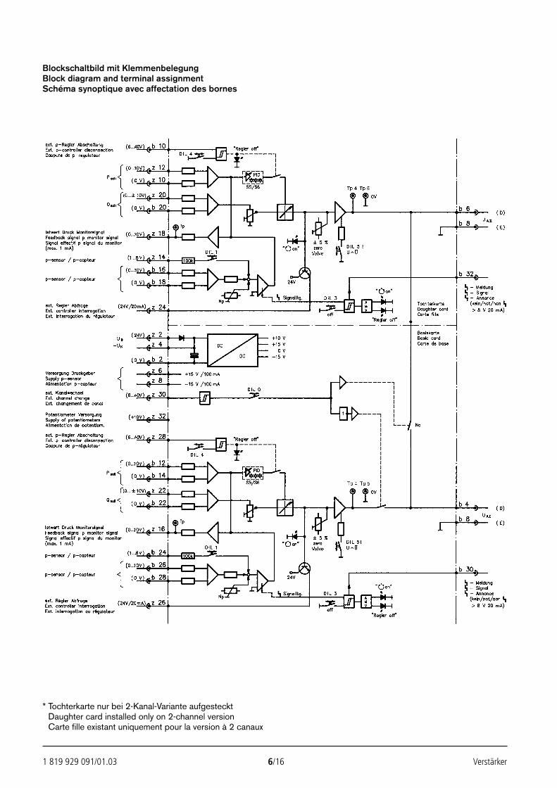
1 819 929 091/01.03 6/16 Verstärker
Blockschaltbild mit KlemmenbelegungBlock diagram and terminal assignmentSchéma synoptique avec affectation des bornes
* Tochterkarte nur bei 2-Kanal-Variante aufgesteckt* Daughter card installed only on 2-channel version* Carte fille existant uniquement pour la version à 2 canaux
24389_4030_001-016 25.02.2003 9:21 Uhr Seite 6
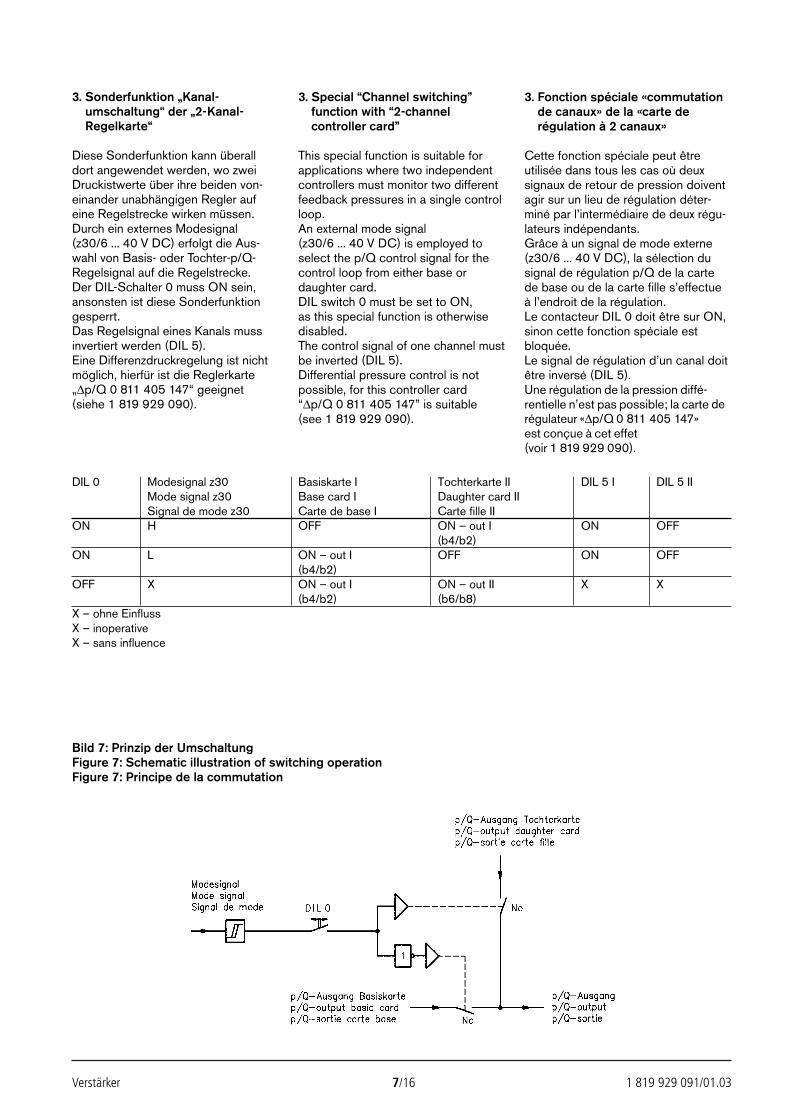
Verstärker 7/16 1 819 929 091/01.03
3. Sonderfunktion „Kanal-umschaltung“ der „2-Kanal-Regelkarte“
Diese Sonderfunktion kann überalldort angewendet werden, wo zweiDruckistwerte über ihre beiden von-einander unabhängigen Regler aufeine Regelstrecke wirken müssen.Durch ein externes Modesignal(z30/6 ... 40 V DC) erfolgt die Aus-wahl von Basis- oder Tochter-p/Q-Regelsignal auf die Regelstrecke.Der DIL-Schalter 0 muss ON sein,ansonsten ist diese Sonderfunktiongesperrt.Das Regelsignal eines Kanals mussinvertiert werden (DIL 5).Eine Differenzdruckregelung ist nichtmöglich, hierfür ist die Reglerkarte„∆p/Q 0 811 405 147“ geeignet(siehe 1 819 929 090).
3. Special “Channel switching”function with “2-channelcontroller card”
This special function is suitable forapplications where two independentcontrollers must monitor two differentfeedback pressures in a single controlloop.An external mode signal(z30/6 ... 40 V DC) is employed toselect the p/Q control signal for thecontrol loop from either base ordaughter card.DIL switch 0 must be set to ON, as this special function is otherwisedisabled.The control signal of one channel mustbe inverted (DIL 5).Differential pressure control is notpossible, for this controller card “∆p/Q 0 811 405 147” is suitable(see 1 819 929 090).
3. Fonction spéciale «commutationde canaux» de la «carte derégulation à 2 canaux»
Cette fonction spéciale peut êtreutilisée dans tous les cas où deuxsignaux de retour de pression doiventagir sur un lieu de régulation déter-miné par l’intermédiaire de deux régu-lateurs indépendants.Grâce à un signal de mode externe(z30/6 ... 40 V DC), la sélection dusignal de régulation p/Q de la carte de base ou de la carte fille s’effectue à l’endroit de la régulation.Le contacteur DIL 0 doit être sur ON,sinon cette fonction spéciale estbloquée.Le signal de régulation d’un canal doitêtre inversé (DIL 5).Une régulation de la pression diffé-rentielle n’est pas possible; la carte derégulateur «∆p/Q 0 811 405 147»est conçue à cet effet (voir 1 819 929 090).
DIL 0 Modesignal z30 Basiskarte I Tochterkarte II DIL 5 I DIL 5 IIMode signal z30 Base card I Daughter card IISignal de mode z30 Carte de base I Carte fille II
ON H OFF ON – out I ON OFF(b4/b2)
ON L ON – out I OFF ON OFF(b4/b2)
OFF X ON – out I ON – out II X X(b4/b2) (b6/b8)
X – ohne EinflussX – inoperativeX – sans influence
Bild 7: Prinzip der UmschaltungFigure 7: Schematic illustration of switching operationFigure 7: Principe de la commutation
24389_4030_001-016 25.02.2003 9:21 Uhr Seite 7
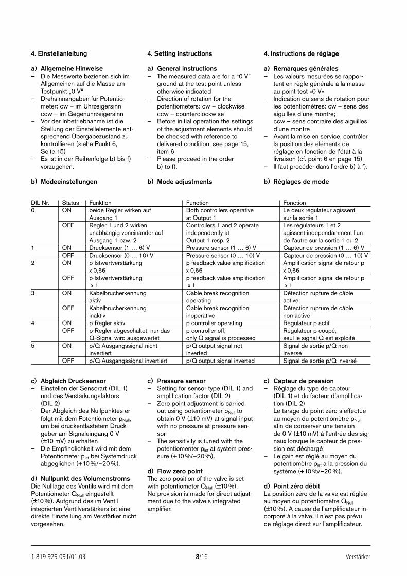
1 819 929 091/01.03 8/16 Verstärker
4. Einstellanleitung
a) Allgemeine Hinweise– Die Messwerte beziehen sich im
Allgemeinen auf die Masse amTestpunkt „0 V“
– Drehsinnangaben für Potentio-meter: cw – im Uhrzeigersinnccw – im Gegenuhrzeigersinn
– Vor der Inbetriebnahme ist dieStellung der Einstellelemente ent-sprechend Übergabezustand zukontrollieren (siehe Punkt 6, Seite 15)
– Es ist in der Reihenfolge b) bis f)vorzugehen.
b) Modeeinstellungen
4. Setting instructions
a) General instructions– The measured data are for a “0 V”
ground at the test point unlessotherwise indicated
– Direction of rotation for thepotentiometers: cw – clockwiseccw – counterclockwise
– Before initial operation the settingsof the adjustment elements shouldbe checked with reference todelivered condition, see page 15,item 6
– Please proceed in the order b) to f).
b) Mode adjustments
4. Instructions de réglage
a) Remarques générales– Les valeurs mesurées se rappor-
tent en règle générale à la masseau point test «0 V»
– Indication du sens de rotation pourles potentiomètres: cw – sens desaiguilles d’une montre; ccw – sens contraire des aiguillesd’une montre
– Avant la mise en service, contrôlerla position des éléments deréglage en fonction de l’état à lalivraison (cf. point 6 en page 15)
– Il faut procéder dans l’ordre b) à f).
b) Réglages de mode
c) Abgleich Drucksensor– Einstellen der Sensorart (DIL 1)
und des Verstärkungsfaktors(DIL 2)
– Der Abgleich des Nullpunktes er-folgt mit dem Potentiometer pNull,um bei druckentlastetem Druck-geber am Signaleingang 0 V(±10 mV) zu erhalten
– Die Empfindlichkeit wird mit demPotentiometer pist bei Systemdruckabgeglichen (+10 %/–20 %).
d) Nullpunkt des VolumenstromsDie Nulllage des Ventils wird mit demPotentiometer QNull eingestellt(±10 %). Aufgrund des im Ventilintegrierten Ventilverstärkers ist einedirekte Einstellung am Verstärker nichtvorgesehen.
c) Pressure sensor– Setting for sensor type (DIL 1) and
amplification factor (DIL 2)– Zero point adjustment is carried
out using potentiometer pNull toobtain 0 V (±10 mV) at signal inputwith no pressure at pressure sen-sor
– The sensitivity is tuned with thepotentiomenter pist at system pres-sure (+10 %/–20 %).
d) Flow zero pointThe zero position of the valve is setwith potentiometer QNull (±10 %). No provision is made for direct adjust-ment due to the valve’s integratedamplifier.
c) Capteur de pression– Réglage du type de capteur
(DIL 1) et du facteur d’amplifica-tion (DIL 2)
– Le tarage du point zéro s’effectueau moyen du potentiomètre pNull
afin de conserver une tension de 0 V (±10 mV) à l’entrée des sig-naux lorsque le capteur de pres-sion est déchargé
– Le gain est réglé au moyen dupotentiomètre pist a la pression dusystème (+10 %/–20 %).
d) Point zéro débitLa position zéro de la valve est régléeau moyen du potentiomètre QNull
(±10 %). A cause de l’amplificateur in-corporé à la valve, il n’est pas prévude réglage direct sur l’amplificateur.
DIL-Nr. Status Funktion Function Fonction0 ON beide Regler wirken auf Both controllers operative Le deux régulateur agissent
Ausgang 1 at Output 1 sur la sortie 1OFF Regler 1 und 2 wirken Controllers 1 and 2 operate Les régulateurs 1 et 2
unabhängig voneinander auf independently at agissent independamment l’unAusgang 1 bzw. 2 Output 1 resp. 2 de l’autre sur la sortie 1 ou 2
1 ON Drucksensor (1 … 6) V Pressure sensor (1 … 6) V Capteur de pression (1 … 6) VOFF Drucksensor (0 … 10) V Pressure sensor (0 … 10) V Capteur de pression (0 … 10) V
2 ON p-Istwertverstärkung p feedback value amplification Amplification signal de retour px 0,66 x 0,66 x 0,66
OFF p-Istwertverstärkung p feedback value amplification Amplification signal de retour px 1 x 1 x 1
3 ON Kabelbrucherkennung Cable break recognition Détection rupture de câble aktiv operating active
OFF Kabelbrucherkennung Cable break recognition Détection rupture de câbleinaktiv inoperative non active
4 ON p-Regler aktiv p controller operating Régulateur p actifOFF p-Regler abgeschaltet, nur das p controller off, Régulateur p coupé,
Q-Signal wird ausgewertet only Q signal is processed seul le signal Q est exploité5 ON p/Q-Ausgangssignal nicht p/Q output signal not Signal de sortie p/Q non
invertiert inverted inverséOFF p/Q-Ausgangssignal invertiert p/Q output signal inverted Signal de sortie p/Q inversé
24389_4030_001-016 25.02.2003 9:21 Uhr Seite 8
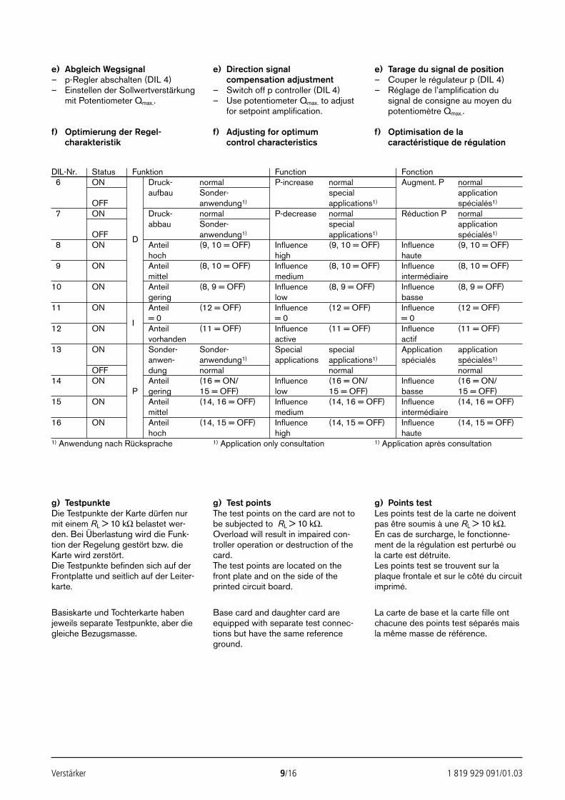
Verstärker 9/16 1 819 929 091/01.03
DIL-Nr. Status Funktion Function Fonction6 ON Druck- normal P-increase normal Augment. P normal
aufbau Sonder- special applicationOFF anwendung1) applications1) spécialés1)
7 ON Druck- normal P-decrease normal Réduction P normalabbau Sonder- special application
OFF D anwendung1) applications1) spécialés1)
8 ON Anteil (9, 10 = OFF) Influence (9, 10 = OFF) Influence (9, 10 = OFF)hoch high haute
9 ON Anteil (8, 10 = OFF) Influence (8, 10 = OFF) Influence (8, 10 = OFF)mittel medium intermédiaire
10 ON Anteil (8, 9 = OFF) Influence (8, 9 = OFF) Influence (8, 9 = OFF)gering low basse
11 ON Anteil (12 = OFF) Influence (12 = OFF) Influence (12 = OFF)
I = 0 = 0 = 012 ON Anteil (11 = OFF) Influence (11 = OFF) Influence (11 = OFF)
vorhanden active actif13 ON Sonder- Sonder- Special special Application application
anwen- anwendung1) applications applications1) spécialés spécialés1)
OFF dung normal normal normal14 ON Anteil (16 = ON/ Influence (16 = ON/ Influence (16 = ON/
P gering 15 = OFF) low 15 = OFF) basse 15 = OFF)15 ON Anteil (14, 16 = OFF) Influence (14, 16 = OFF) Influence (14, 16 = OFF)
mittel medium intermédiaire16 ON Anteil (14, 15 = OFF) Influence (14, 15 = OFF) Influence (14, 15 = OFF)
hoch high haute1) Anwendung nach Rücksprache 1) Application only consultation 1) Application après consultation1)
e) Abgleich Wegsignal– p-Regler abschalten (DIL 4)– Einstellen der Sollwertverstärkung
mit Potentiometer Qmax..
f) Optimierung der Regel-charakteristik
e) Direction signalcompensation adjustment
– Switch off p controller (DIL 4)– Use potentiometer Qmax. to adjust
for setpoint amplification.
f) Adjusting for optimumcontrol characteristics
e) Tarage du signal de position– Couper le régulateur p (DIL 4)– Réglage de l’amplification du
signal de consigne au moyen dupotentiomètre Qmax..
f) Optimisation de lacaractéristique de régulation
g) TestpunkteDie Testpunkte der Karte dürfen nurmit einem RL > 10 kΩ belastet wer-den. Bei Überlastung wird die Funk-tion der Regelung gestört bzw. dieKarte wird zerstört.Die Testpunkte befinden sich auf derFrontplatte und seitlich auf der Leiter-karte.
g) Test pointsThe test points on the card are not tobe subjected to RL > 10 kΩ.Overload will result in impaired con-troller operation or destruction of thecard.The test points are located on thefront plate and on the side of theprinted circuit board.
g) Points testLes points test de la carte ne doiventpas être soumis à une RL > 10 kΩ.En cas de surcharge, le fonctionne-ment de la régulation est perturbé oula carte est détruite.Les points test se trouvent sur laplaque frontale et sur le côté du circuitimprimé.
Basiskarte und Tochterkarte haben jeweils separate Testpunkte, aber diegleiche Bezugsmasse.
Base card and daughter card areequipped with separate test connec-tions but have the same referenceground.
La carte de base et la carte fille ontchacune des points test séparés maisla même masse de référence.
24389_4030_001-016 25.02.2003 9:21 Uhr Seite 9
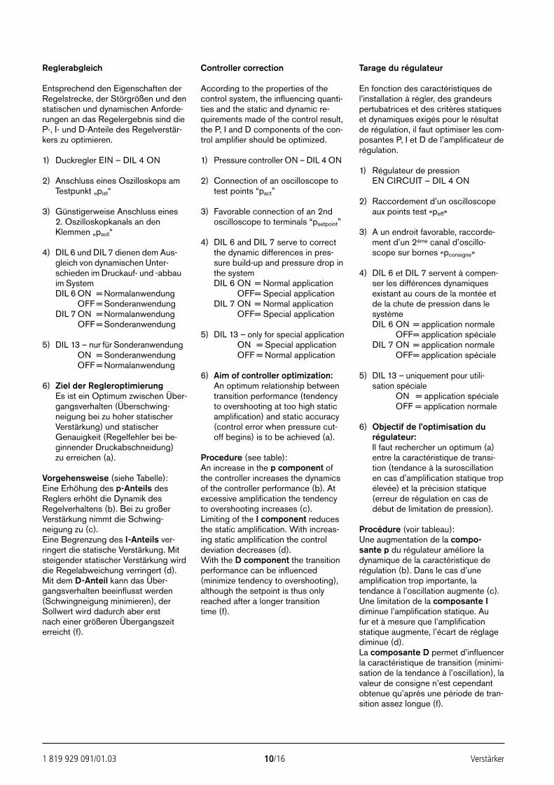
1 819 929 091/01.03 10/16 Verstärker
Reglerabgleich
Entsprechend den Eigenschaften derRegelstrecke, der Störgrößen und denstatischen und dynamischen Anforde-rungen an das Regelergebnis sind dieP-, I- und D-Anteile des Regelverstär-kers zu optimieren.
1) Duckregler EIN – DIL 4 ON
2) Anschluss eines Oszilloskops amTestpunkt „pist“
3) Günstigerweise Anschluss eines 2. Oszilloskopkanals an denKlemmen „psoll“
4) DIL 6 und DIL 7 dienen dem Aus-gleich von dynamischen Unter-schieden im Druckauf- und -abbauim SystemDIL 6 ON = Normalanwendung
OFF = SonderanwendungDIL 7 ON = Normalanwendung
OFF = Sonderanwendung
5) DIL 13 – nur für SonderanwendungDIL 6 ON = Sonderanwendung
OFF = Normalanwendung
6) Ziel der RegleroptimierungEs ist ein Optimum zwischen Über-gangsverhalten (Überschwing-neigung bei zu hoher statischerVerstärkung) und statischerGenauigkeit (Regelfehler bei be-ginnender Druckabschneidung) zu erreichen (a).
Vorgehensweise (siehe Tabelle):Eine Erhöhung des p-Anteils desReglers erhöht die Dynamik desRegelverhaltens (b). Bei zu großerVerstärkung nimmt die Schwing-neigung zu (c). Eine Begrenzung des I-Anteils ver-ringert die statische Verstärkung. Mitsteigender statischer Verstärkung wirddie Regelabweichung verringert (d). Mit dem D-Anteil kann das Über-gangsverhalten beeinflusst werden(Schwingneigung minimieren), derSollwert wird dadurch aber erst nach einer größeren Übergangszeiterreicht (f).
Controller correction
According to the properties of thecontrol system, the influencing quanti-ties and the static and dynamic re-quirements made of the control result,the P, I and D components of the con-trol amplifier should be optimized.
1) Pressure controller ON – DIL 4 ON
2) Connection of an oscilloscope totest points “pact”
3) Favorable connection of an 2ndoscilloscope to terminals “psetpoint”
4) DIL 6 and DIL 7 serve to correctthe dynamic differences in pres-sure build-up and pressure drop inthe systemDIL 6 ON = Normal application
OFF= Special applicationDIL 7 ON = Normal application
OFF= Special application
5) DIL 13 – only for special applicationDIL 6 ON = Special application
OFF = Normal application
6) Aim of controller optimization:An optimum relationship betweentransition performance (tendencyto overshooting at too high staticamplification) and static accuracy(control error when pressure cut-off begins) is to be achieved (a).
Procedure (see table):An increase in the p component ofthe controller increases the dynamicsof the controller performance (b). Atexcessive amplification the tendencyto overshooting increases (c). Limiting of the I component reducesthe static amplification. With increas-ing static amplification the controldeviation decreases (d).With the D component the transitionperformance can be influenced(minimize tendency to overshooting),although the setpoint is thus onlyreached after a longer transition time (f).
Tarage du régulateur
En fonction des caractéristiques del’installation à régler, des grandeurspertubatrices et des critères statiqueset dynamiques exigés pour le résultatde régulation, il faut optimiser les com-posantes P, I et D de l’amplificateur derégulation.
1) Régulateur de pressionEN CIRCUIT – DIL 4 ON
2) Raccordement d’un oscilloscopeaux points test «peff»
3) A un endroit favorable, raccorde-ment d’un 2éme canal d’oscillo-scope sur bornes «pconsigne»
4) DIL 6 et DIL 7 servent à compen-ser les différences dynamiquesexistant au cours de la montée etde la chute de pression dans lesystèmeDIL 6 ON = application normale
OFF= application spécialeDIL 7 ON = application normale
OFF= application spéciale
5) DIL 13 – uniquement pour utili-sation spécialeDIL 6 ON = application spéciale
OFF = application normale
6) Objectif de l’optimisation durégulateur:Il faut rechercher un optimum (a)entre la caractéristique de transi-tion (tendance à la suroscillationen cas d’amplification statique tropélevée) et la précision statique(erreur de régulation en cas dedébut de limitation de pression).
Procédure (voir tableau):Une augmentation de la compo-sante p du régulateur améliore ladynamique de la caractéristique derégulation (b). Dans le cas d’uneamplification trop importante, latendance à l’oscillation augmente (c).Une limitation de la composante Idiminue l’amplification statique. Au fur et à mesure que l’amplificationstatique augmente, l’écart de réglagediminue (d). La composante D permet d’influencerla caractéristique de transition (minimi-sation de la tendance à l’oscillation), lavaleur de consigne n’est cependantobtenue qu’après une période de tran-sition assez longue (f).
24389_4030_001-016 25.02.2003 9:21 Uhr Seite 10
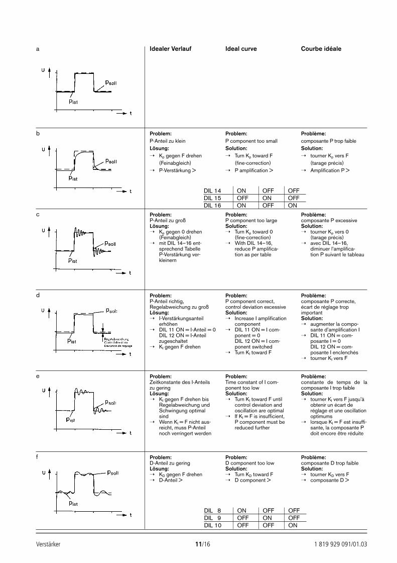
Verstärker 11/16 1 819 929 091/01.03
Problem:P-Anteil zu kleinLösung: Kp gegen F drehen
(Feinabgleich) P-Verstärkung >
Problem:P component too smallSolution: Turn Kp toward F
(fine-correction) P amplification >
Problème:composante P trop faibleSolution: tourner Kp vers F
(tarage précis) Amplification P >
Problem:P-Anteil zu großLösung: Kp gegen 0 drehen
(Feinabgleich) mit DIL 14–16 ent-
sprechend TabelleP-Verstärkung ver-kleinern
Problem:P component too largeSolution: Turn Kp toward 0
(fine-correction) With DIL 14–16,
reduce P amplifica-tion as per table
Problème:composante P excessiveSolution: tourner Kp vers 0
(tarage précis) avec DIL 14–16,
diminuer l’amplifica-tion P suivant le tableau
Problem:P-Anteil richtig,Regelabweichung zu großLösung: I-Verstärkungsanteil
erhöhen DIL 11 ON = I-Anteil = 0
DIL 12 ON = I-Anteilzugeschaltet
KI gegen F drehen
Problem:P component correct,control deviation excessiveSolution: Increase I amplification
component DIL 11 ON = I com-
ponent = 0DIL 12 ON = I com-ponent switched
Turn KI toward F
Problème:composante P correcte,écart de réglage tropimportantSolution: augmenter la compo-
sante d’amplification I DIL 11 ON = com-
posante I = 0DIL 12 ON = com-posante I enclenchés
tourner KI vers F
Problem:Zeitkonstante des I-Anteilszu geringLösung: KI gegen F drehen bis
Regelabweichung undSchwingung optimalsind
Wenn KI = F nicht aus-reicht, muss P-Anteilnoch verringert werden
Problem:Time constant of I com-ponent too lowSolution: Turn KI toward F until
control deviation andoscillation are optimal
If KI = F is insufficient, P component must bereduced further
Problème:constante de temps de lacomposante I trop faibleSolution: tourner KI vers F jusqu’à
obtenir un écart deréglage et une oscillationoptimums
lorsque KI = F est insuffi-sante, la composante Pdoit encore être réduite
Problem:D-Anteil zu geringLösung: KD gegen F drehen D-Anteil >
Problem:D component too lowSolution: Turn KD toward F D component >
Problème:composante D trop faibleSolution: tourner KD vers F composante D >
a
b
c
d
e
f
DIL 14 ON OFF OFFDIL 15 OFF ON OFFDIL 16 ON OFF ON
DIL 8 ON OFF OFFDIL 9 OFF ON OFFDIL 10 OFF OFF ON
Idealer Verlauf Ideal curve Courbe idéale
24389_4030_001-016 25.02.2003 9:22 Uhr Seite 11
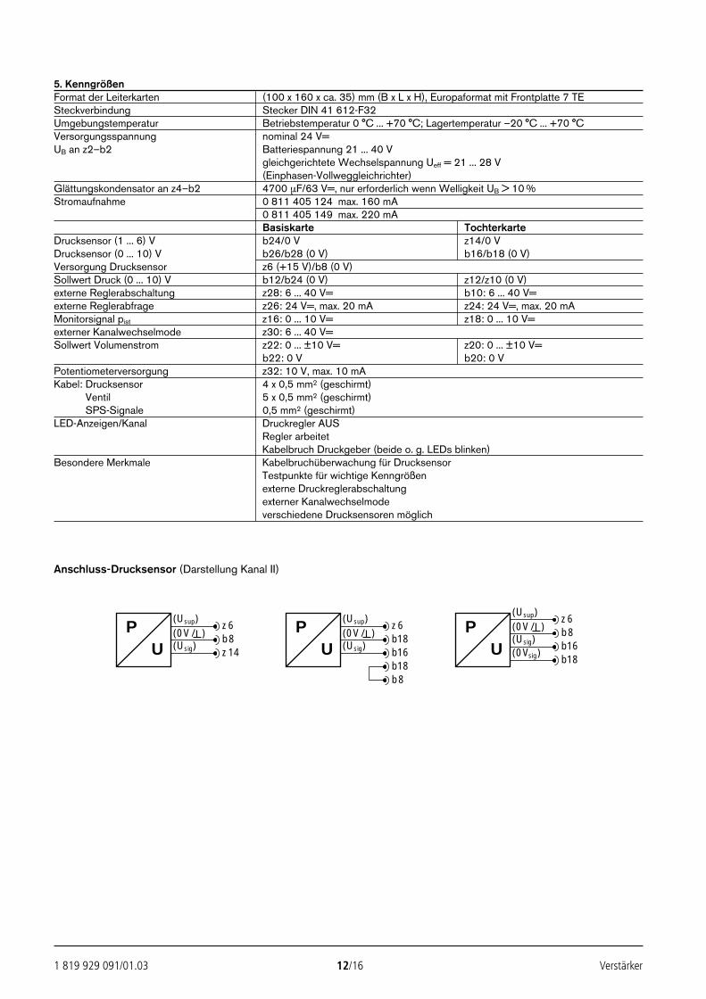
1 819 929 091/01.03 12/16 Verstärker
5. KenngrößenFormat der Leiterkarten (100 x 160 x ca. 35) mm (B x L x H), Europaformat mit Frontplatte 7 TESteckverbindung Stecker DIN 41 612-F32Umgebungstemperatur Betriebstemperatur 0 °C ... +70 °C; Lagertemperatur –20 °C ... +70 °CVersorgungsspannung nominal 24 V=UB an z2–b2 Batteriespannung 21 ... 40 V
gleichgerichtete Wechselspannung Ueff = 21 ... 28 V(Einphasen-Vollweggleichrichter)
Glättungskondensator an z4–b2 4700 µF/63 V=, nur erforderlich wenn Welligkeit UB > 10 %Stromaufnahme 0 811 405 124 max. 160 mA
0 811 405 149 max. 220 mABasiskarte Tochterkarte
Drucksensor (1 ... 6) V b24/0 V z14/0 VDrucksensor (0 ... 10) V b26/b28 (0 V) b16/b18 (0 V)Versorgung Drucksensor z6 (+15 V)/b8 (0 V)Sollwert Druck (0 ... 10) V b12/b24 (0 V) z12/z10 (0 V)externe Reglerabschaltung z28: 6 ... 40 V= b10: 6 ... 40 V=externe Reglerabfrage z26: 24 V=, max. 20 mA z24: 24 V=, max. 20 mAMonitorsignal pist z16: 0 ... 10 V= z18: 0 ... 10 V=externer Kanalwechselmode z30: 6 ... 40 V=Sollwert Volumenstrom z22: 0 ... ±10 V= z20: 0 ... ±10 V=
b22: 0 V b20: 0 VPotentiometerversorgung z32: 10 V, max. 10 mAKabel: Drucksensor 4 x 0,5 mm2 (geschirmt)Kabel: Ventil 5 x 0,5 mm2 (geschirmt)Kabel: SPS-Signale 0,5 mm2 (geschirmt)LED-Anzeigen/Kanal Druckregler AUS
Regler arbeitetKabelbruch Druckgeber (beide o. g. LEDs blinken)
Besondere Merkmale Kabelbruchüberwachung für DrucksensorTestpunkte für wichtige Kenngrößenexterne Druckreglerabschaltungexterner Kanalwechselmodeverschiedene Drucksensoren möglich
P(Usup)P
UU
z6(0V/ ) b18(Usig) b16
b18b8
(Usup) z6(0V/ ) b8(Usig) z14
(Usup)
PU
z6(0V/ ) b8(Usig) b16(0Vsig)
b18
Anschluss-Drucksensor (Darstellung Kanal II)
24389_4030_001-016 25.02.2003 9:22 Uhr Seite 12
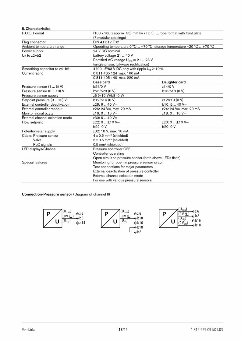
Verstärker 13/16 1 819 929 091/01.03
5. CharacteristicsP.C.C. Format (100 x 160 x approx. 35) mm (w x l x h), Europe format with front plate
(7 modular spacings)Plug connector DIN 41 612-F32Ambient temperature range Operating temperature 0 °C ... +70 °C; storage temperature –20 °C ... +70 °CPower supply 24 V DC nominal UB to z2–b2 battery voltage 21 ... 40 V
Rectified AC voltage Urms = 21 ... 28 V(single-phase, full-wave rectification)
Smoothing capacitor to z4–b2 4700 µF/63 V DC only with ripple UB > 10 %Current rating 0 811 405 124 max. 160 mA
0 811 405 149 max. 220 mABase card Daughter card
Pressure sensor (1 ... 6) V) b24/0 V z14/0 VPressure sensor (0 ... 10) V b26/b28 (0 V) b16/b18 (0 V)Pressure sensor supply z6 (+15 V)/b8 (0 V)Setpoint pressure (0 ... 10) V b12/b14 (0 V) z12/z10 (0 V)External controller deactivation z28: 6 ... 40 V= b10: 6 ... 40 V=External controller readout z26: 24 V=, max. 20 mA z24: 24 V=, max. 20 mAMonitor signal pactual z16: 0 ... 10 V= z18: 0 ... 10 V=External channel selection mode z30: 6 ... 40 V=Flow setpoint z22: 0 ... ±10 V= z20: 0 ... ±10 V=
b22: 0 V b20: 0 VPotentiometer supply z32: 10 V, max. 10 mACable: Pressure sensor 4 x 0.5 mm2 (shielded)Cable: Valve 5 x 0.5 mm2 (shielded)Cable: PLC signals 0.5 mm2 (shielded)LED displays/Channel Pressure controller OFF
Controller operatingOpen circuit to pressure sensor (both above LEDs flash)
Special features Monitoring for open in pressure sensor circuitTest connections for major parametersExternal deactivation of pressure controllerExternal channel selection modeFor use with various pressure sensors
Connection-Pressure sensor (Diagram of channel II)
P(Usup)P
UU
z6(0V/ ) b18(Usig) b16
b18b8
(Usup) z6(0V/ ) b8(Usig) z14
(Usup)
PU
z6(0V/ ) b8(Usig) b16(0Vsig)
b18
24389_4030_001-016 25.02.2003 9:22 Uhr Seite 13
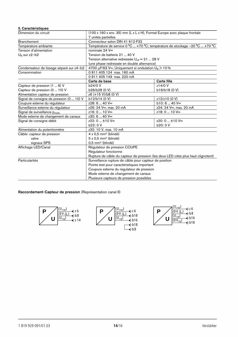
1 819 929 091/01.03 14/16 Verstärker
5. CaractéristiquesDimension du circuit (100 x 160 x env. 35) mm (L x L x H), Format Europe avec plaque frontale
7 unités partiellesBranchement Connecteur selon DIN 41 612-F32Température ambiante Température de service 0 °C ... +70 °C; température de stockage –20 °C ... +70 °CTension d’alimentation nominale 24 V=UB sur z2–b2 Tension de batterie 21 ... 40 V
Tension alternative redressée Ueff = 21 ... 28 V(une phase redressée en double alternance)
Condensateur de lissage séparé sur z4–b2 4700 µF/63 V=, Uniquement si ondulation UB > 10 %Consommation 0 811 405 124 max. 160 mA
0 811 405 149 max. 220 mACarte de base Carte fille
Capteur de pression (1 ... 6) V b24/0 V z14/0 VCapteur de pression (0 ... 10) V b26/b28 (0 V) b16/b18 (0 V)Alimentation capteur de pression z6 (+15 V)/b8 (0 V)Signal de consigne de pression (0 ... 10) V b12/b14 (0 V) z12/z10 (0 V)Coupure externe du régulateur z28: 6 ... 40 V= b10: 6 ... 40 V=Surveillance externe du régulateur z26: 24 V=, max. 20 mA z24: 24 V=, max. 20 mASignal de surveillance préelle z16: 0 ... 10 V= z18: 0 ... 10 V=Mode externe de changement de canaux z30: 6 ... 40 V=Signal de consigne débit z22: 0 ... ±10 V= z20: 0 ... ±10 V=
b22: 0 V b20: 0 VAlimentation du potentiomètre z32: 10 V, max. 10 mACâble: capteur de pression 4 x 0,5 mm2 (blindé)Cables: valve 5 x 0,5 mm2 (blindé)Cables: signaux SPS 0,5 mm2 (blindé)Affichage LED/Canal Régulateur de pression COUPE
Régulateur fonctionneRupture de câble du capteur de pression (les deux LED cités plus haut clignotent)
Particularités Surveillance rupture de câble pour capteur de positionPoints test pour caractéristiques importantCoupure externe du régulateur de pressionMode externe de changement de canauxPlusieurs capteurs de pression possibles
Raccordement-Capteur de pression (Représentation canal II)
P(Usup)P
UU
z6(0V/ ) b18(Usig) b16
b18b8
(Usup) z6(0V/ ) b8(Usig) z14
(Usup)
PU
z6(0V/ ) b8(Usig) b16(0Vsig)
b18
24389_4030_001-016 25.02.2003 9:22 Uhr Seite 14
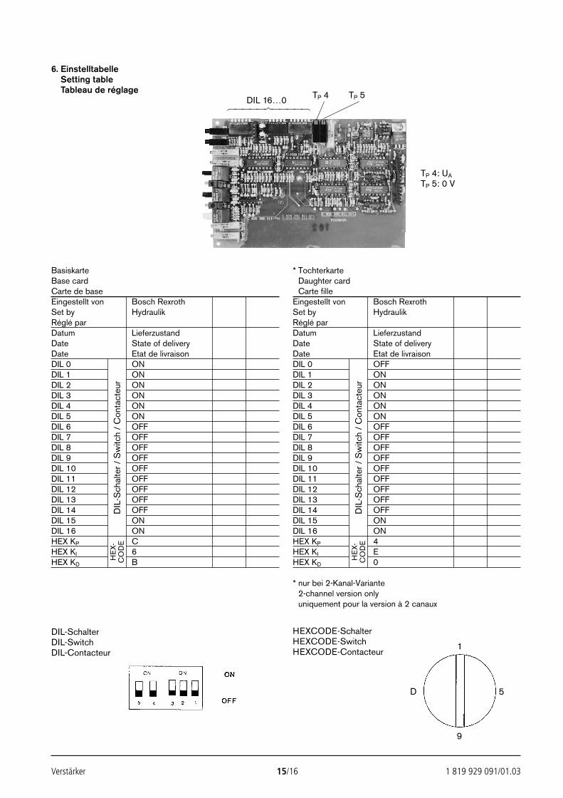
Verstärker 15/16 1 819 929 091/01.03
6. EinstelltabelleSetting tableTableau de réglage
DIL 16…0
TP 4 TP 5
BasiskarteBase cardCarte de baseEingestellt von Bosch RexrothSet by HydraulikRéglé parDatum LieferzustandDate State of deliveryDate Etat de livraisonDIL 0 ONDIL 1 ONDIL 2 ONDIL 3 ONDIL 4 ONDIL 5 ONDIL 6 OFFDIL 7 OFFDIL 8 OFFDIL 9 OFFDIL 10 OFFDIL 11 OFFDIL 12 OFFDIL 13 OFFDIL 14 OFFDIL 15 ONDIL 16 ONHEX KP CHEX KI 6HEX KD B
DIL
-Sch
alte
r / S
witc
h /
Con
tact
eur
HE
X-C
OD
E
* Tochterkarte* Daughter card* Carte filleEingestellt von Bosch RexrothSet by HydraulikRéglé parDatum LieferzustandDate State of deliveryDate Etat de livraisonDIL 0 OFFDIL 1 ONDIL 2 ONDIL 3 ONDIL 4 ONDIL 5 ONDIL 6 OFFDIL 7 OFFDIL 8 OFFDIL 9 OFFDIL 10 OFFDIL 11 OFFDIL 12 OFFDIL 13 OFFDIL 14 OFFDIL 15 ONDIL 16 ONHEX KP 4HEX KI EHEX KD 0
* nur bei 2-Kanal-Variante* 2-channel version only* uniquement pour la version à 2 canaux
DIL
-Sch
alte
r / S
witc
h /
Con
tact
eur
HE
X-C
OD
E
HEXCODE-SchalterHEXCODE-SwitchHEXCODE-Contacteur
DIL-SchalterDIL-SwitchDIL-Contacteur
1
9
D 5
TP 4: UA
TP 5: 0 V
24389_4030_001-016 25.02.2003 9:22 Uhr Seite 15

Bosch Rexroth AG Die angegebenen Daten dienen allein derIndustrial Hydraulics Produktbeschreibung. Eine Aussage über eineD-97813 Lohr am Main bestimmte Beschaffenheit oder eine Eignung fürZum Eisengießer 1 D-97816 Lohr am Main einen bestimmten Einsatzzweck kann ausTelefon 0 93 52/18-0 unseren Angaben nicht abgeleitet werden. Es istTelefax 0 93 52/18-23 58 Telex 6 89 418-0 zu beachten, dass unsere Produkte einemeMail [email protected] natürlichen Verschleiß- und AlterungsprozessInternet www.boschrexroth.de unterliegen.
1 819 929 091/01.03 16/16 Verstärker
24389_4030_001-016 25.02.2003 9:22 Uhr Seite 16