Embed Size (px)
Citation preview
Progress In Electromagnetics Research, Vol. 109, 441–474, 2010
INDOOR LOCALIZATION WITH WIRELESS SENSORNETWORKS
S. A. Mitilineos, D. M. Kyriazanos, O. E. SegouJ. N. Goufas and S. C. A. Thomopoulos
National Center for Scientific Research “Demokritos”Institute of Informatics and TelecommunicationsPatriarchou Grigoriou kai Neapoleos Str., Agia Paraskevi 15310, Greece
Abstract—Wireless Sensor Networks (WSNs) have attracted a greatdeal of research interest during the last few years. Potentialapplications make them ideal for the development of the envisionedworld of ubiquitous and pervasive computing. Localization is a keyaspect of such networks, since the knowledge of a sensor’s location iscritical in order to process information originating from this sensor,or to actuate responses to the environment, or to infer regarding anemerging situation etc. Indoor localization in the literature is basedon various techniques, ranging from simple Received-Signal-Strength(RSS) to the more demanding Time-of-Arrival (ToA) or Direction-of-Arrival (DoA) of the incoming signals. In the context of severalEU research projects, various WSN platforms for indoor localizationhave been developed, evaluated and tested within real-world emergencymedical services applications. These platforms were selected in orderto deal with all principal localization techniques, namely RSSI, ToAand DoA. Deployment and real-world considerations are discussed,measurements results are presented and overall system evaluationconclusions are drawn regarding indoor localization capabilities ofWSNs.
1. INTRODUCTION
Wireless Sensor Networks (WSNs) are a class of distributedcomputing and communication systems that are an integral partof the physical space they inhabit [1]. Albeit low profile, limitedcomputational power and sparse energy resources, their most
Received 28 June 2010, Accepted 9 August 2010, Scheduled 6 November 2010Corresponding author: S. A. Mitilineos ([email protected]).
442 Mitilineos et al.
interesting feature is the reasoning of and reaction to the world thatsurrounds them. Smart environments represent the next evolutionarydevelopment step in building, utilities, industrial, home, shipboard,and transportation systems automation [2]. This bridge to thephysical world has enabled a growing bouquet of potential services,ranging from commercial (environmental monitoring, industrialsensing and diagnostics, context-aware computing etc.) to military(infrastructure protection, battlefield awareness, on-field navigationetc.) applications [3].
Information about location of wireless sensors is crucial for thesuccessful deployment and operation of such networks. Passing overthe case of pre-recorded location, which is cumbersome and impracticalin mass-scale WSNs, there is a growing interest in wireless sensor andWSN-based localization. Location information is considered to addmany potential applications to telecommunications systems, such asfraud protection, fleet management, location-aware network access,person/asset tracking, navigation etc. Furthermore, Ambient AssistedLiving (AAL) platforms strongly rely on an accurate underlyinglocalization system, in order to provide timely and reliable servicesto elderly users. Furthermore, first responders’ reaction quality isconsidered to be improved to a large extent in the case where location-related information is available.
In this paper, we aim at demonstrating evaluation resultsregarding implementation, measurements and real-world experienceof WSN-based localization for AAL platforms. More specifically, inthe context of the “EMERGE” EU research project, a variety oflocalization systems has been tested under the scope of providing real-time emergency medical services to elderly users [4–11]. The breadthand depth of the presented results aim at providing informationon hands-on experience with promising technologies for indoorlocalization to interested researchers and developers.
In the following, a short discussion about localization techniquesprecedes a detailed presentation and analysis of the experimentalsystems and results presented herein. For this analysis, the templateproposed by Jedlitschka et al. is used [12], in order to comply with awell accepted format for documents of similar scope. Finally, a shortdiscussion about real world deployment considerations is cited beforeconcluding the paper.
2. LOCALIZATION TECHNIQUES — OVERVIEW
Several localization techniques have been proposed in the literature.The Global Positioning System (GPS) provides global coverage but
Progress In Electromagnetics Research, Vol. 109, 2010 443
specialized equipment is needed, which is energy inefficient and mostlyineligible for WSNs, except for the case of limited number of sensorswith extended battery capabilities. Furthermore, GPS is not capableof operating indoors, because of the large attenuation introduced bybuildings’ walls and ceilings; therefore it cannot comprise a ubiquitouslocalization method.
Radio frequency techniques have been alternatively suggested inorder to locate wireless units. Radio frequency position locationsystems are classified into two broad categories: Direction-finding (DF)and range-based (RB) systems [13]. DF systems utilize antenna arraysand Direction-of-Arrival (DoA) estimation techniques in order to locatethe Mobile Station (MS), and are mainly used in areas with limitedclutter [14–20]. On the other hand, RB systems measure the distancebetween the MS and a number of Base Stations (BSs), and then theMS’s position arises as the intersection point of the correspondingcurves. The range of the MS is calculated using either Time-of-Arrival(ToA) or Received Signal Strength (RSS) measurements [15, 17, 21, 22].
DoA and ToA measurements are not available to inexpensivesystems [23], due to the need for antenna arrays or timesynchronization respectively. Also, DoA and ToA measurementsmay be degraded due to shadowing and multipath. However, UltraWideBand (UWB) ToA systems are most efficient and robust, due tothe extended capabilities of rejecting multipath. Unfortunately, UWB-ToA is the most expensive and energy consuming localization techniqueknown today.
On the contrary, RSS indicating-capable equipment is widelyavailable and provides a cost-effective means of position location. RSSbased distance estimation may also be degraded due to shadowing aswell as multipath, but small-scale fading may be smoothed out byaveraging over time or equivalent distance and frequency band [24].Also, RSS based positioning may be performed by using Scene-Analysis (SA) like in the indoor cases presented in [25–29]. Theresulting indoors accuracy is considered to be satisfactory, but onsitecalibration measurements are not practical, and some times notpossible. Alternatively, onsite RSS propagation model estimationmay be used in order to leverage indoor accuracy [15, 30, 31]. Inoutdoor cases, topographical maps and propagation-prediction tools,as well as statistical modeling, neural networks and particle filtershave been used instead of RSS pre-measurements [2, 14, 22, 32, 33–38].Furthermore, specialized techniques for WSNs have been introduced inorder to enhance localization accuracy and reduce uncertainty [22, 39].Concluding, RSS-based positioning is ubiquitous and inexpensive andsuch techniques are well eligible provided that they demonstrate
444 Mitilineos et al.
satisfactory accuracy and require little or not at all offline calibration,prior knowledge of the environment etc..
Under the scope of WSN applications, the criterion of accuracymay be deemed less important and then RSS-based localization seemsto be the most eligible technique. However, in AAL applicationsaccurate localization may grow to a very important factor, e.g., incases where mobility patterns or fall detection of the user are required.Thereupon, the entire range of different localization techniques hasbeen evaluated and tested, and results are presented hereinafter. Morespecifically, we have evaluated and tested the following systems:
i) The Cricket system, which is based on Radio-Frequency (RF) andUltra-Sonic (US) ToA measurements,
ii) The Ubisense platform, which is based on a hybrid combinationof DoA and UWB-ToA measurements, and
iii) The WAX system (Wireless-sensor network using Arduino andXBee), which is an in-house developed prototype, based on theXBee (ZigBee-enabled) radio modules and Arduino microcon-trollers, and performs localization using RSS-SA techniques (SceneAnalysis with Received Signal Strength).
3. BACKGROUND, PROBLEM STATEMENT ANDRESEARCH OBJECTIVE
3.1. Background
The main motivation for proposing and implementing AAL platformsis the observed increase of average age in modern societies. Togetherwith this increase in average age goes an increase in chronic illnessesas well as an observed increasing rate of coexisting morbidities. Theneed for assistance and healthcare to the elderly is becoming moreand more necessary for social as well as for economic reasons. Inmany of the existing AAL platforms there are issues such as lateor false notifications, as well as lack of reliable information, meaningthat sensor fusion of different types of sensors is not widespread yet.Together with a reported low user acceptance, it is safe to conclude that— currently — the preventative assistance to the elderly is incompleteand of low added value.
The EMERGE project aims at implementing an Ambient AssistedLiving Platform (AALP) for offering such medical and healthcareservices, with a specific target on emergency medical services. TheAALP will be based on recording user location and trajectories in orderto recognize the daily routine of a person. Based on daily patternsdeviations, critical situations will be detected in order to initiate
Progress In Electromagnetics Research, Vol. 109, 2010 445
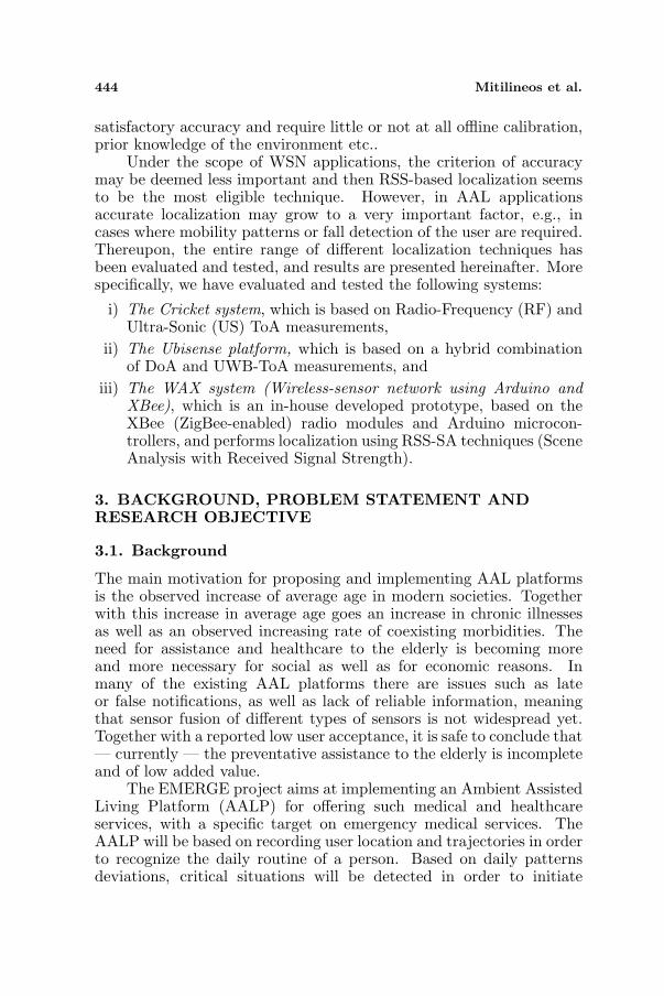
Figure 1. The AALP platform for emergency medical services.
adequate countermeasures. The AALP platform is illustrated byFig. 1. The Real-Time-Location-Server Module (RTLS) is responsiblefor collecting all location information regarding the user and forwardingit to the Home Gateway. On the other hand, there is the AmbientHealth Care System Module (AHCS), which effectively monitors thehealth status of the elderly and consists of vital, environmental andactivity sensor packs. The data from location and other sensors areaggregated by the Home Gateway and forwarded via the WEB to theEmergency Medical System (EMS) server. The EMS Server feeds theEvent Detection Module with data from the RTLS and the AHCSmodules. The Event Detection Module includes a Reasoning Model,which detects deviations from typical behaviors using ontologies and AItechniques. In case of an emergency or abnormal behavior, the EventDetection Module triggers the EMS server, which in turn responds bysending an emergency notification to the First Responders OperationDispatcher. The loop of emergency medical service is closed by doctors,nurses, paramedics etc. who rapidly arrive to the site of the elderly.
Within this context, accurate and timely localization measure-ments provided by the RTLS module were the primary objective ofthe research work of our team within the EMERGE EU project.
3.2. Problem Statement
The problem: localize the assisted person in an indoor environment,with an accuracy and performance high enough to reliably monitor hisactivity and detect falls/injuries, taking also into account ergonomicsand minimizing intrusiveness on the user.
446 Mitilineos et al.
3.3. Research Objective
The research objective concerning the RTLS module was to develop,evaluate and test various WSN-based indoor localization platforms andsystems. Besides the standard Cricket, Ubisense and WAX systems,the experiments also evaluated proposals for further improving theaccuracy, such as a proposed sensor fusion technique as well aspreservation of clear Line-of-Sight (LoS) between transmitter andreceiver, as described in the following sections.
4. HYPOTHESES, PARAMETERS AND VARIABLES
The following parameters were calculated for evaluating the accuracyperformance of the proposed localization techniques and techniques:
• Average accuracy (m): the arithmetic mean value of observedaccuracy measurements; gives a straightforward value for theaccuracy performance.
• Median accuracy (m): the value of accuracy below which 50%of observed accuracy measurements fall.
• 67th percentile (m): the value of accuracy below which 67%of of observed accuracy measurements fall; a performance metricwhich includes most normal observations and circumstances ingeneral.
• 95th percentile (m): the value of accuracy below which 95%of of observed accuracy measurements fall; a performance metricwhich excludes infrequent peaks.
• 2D accuracy: the 2D accuracy in each case is calculated usingPythagoras theorem, namely: d =
√(xest−xreal)2+(yest−yreal)2,
where d denotes the 2D-accuracy and xest, yest, xreal, yreal
denote the estimated and real values of positioning coordinatesrespectively.
• 2D relative accuracy: the 2D relative accuracy is definedin order to provide a common basis for the comparison amongdifferent systems deployed at different environments. The 2Daccuracy is calculated as the ratio of a circular area of π · d2,where d denotes the 2D-accuracy, vs. the area, A, of the deployednetwork, i.e., length times width of the indoor area where thenetwork is deployed. The relative accuracy, dR is calculated bydR = π·d2
A .
Progress In Electromagnetics Research, Vol. 109, 2010 447
5. EXPERIMENTAL DESIGN
5.1. Cricket Localization System
The Cricket localization system consists of a number of wireless nodes(the so-called “crickets”), which may be set to act as either beacons orlisteners. Beacons are static nodes acting as anchored reference pointsand are typically attached to Line-of-Sight (LOS) spots, such as on aroom ceiling. They periodically transmit an ultrasonic pulse, togetherwith an RF pulse bearing a beacon identifier, position coordinatesand other useful data. On the other hand, listeners are attached tofixed or mobile objects that are to be localized. They listen to beacontransmissions and calculate their distance to a nearby beacon usingthe difference between the ToA of RF and ultrasonic pulses. Thedistances to nearby beacons are then used in order to calculate thelistener’s position coordinates by triangulation [6, 40]. Evidently, whilein a typical ToA–based localization system expensive beacon-listenerRF synchronization equipment is needed, with Cricket the need forRF synchronization is eliminated due to the combined usage of RFand ultrasonic pulses; at the same time, the system relies on ToAmeasurements, thus being expected to yield highly accurate positionestimation results.
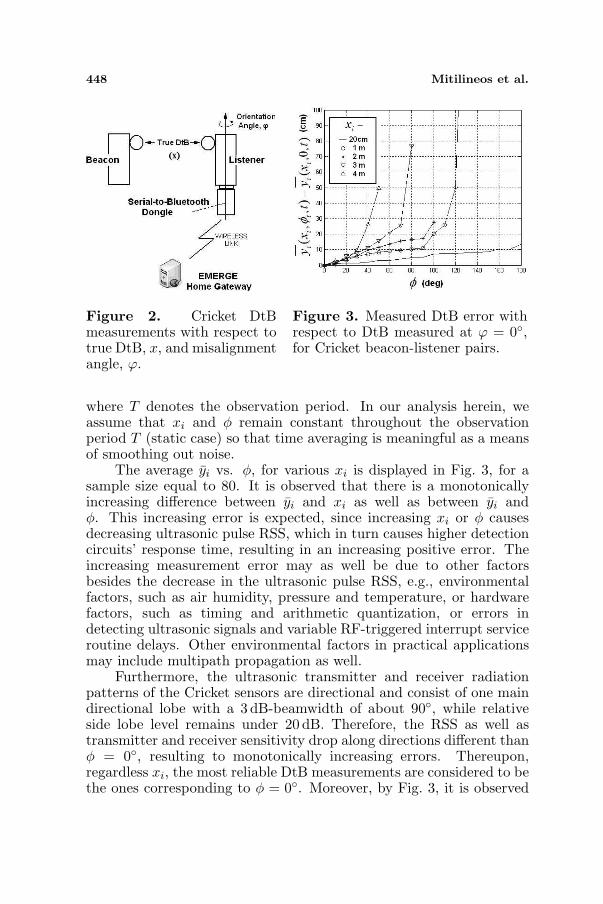
In order to develop a model of the Cricket sensor-performancecharacteristics, a simple testbed was setup as illustrated in Fig. 2. Thistestbed is used in order to evaluate the measured Distance-to-Beacon(DtB) from a listener, denoted by yi, assuming a single listener sensoris used. The beacon and listener are placed parallel to one another,at a manually adjusted ultrasonic transmitter-receiver distance andmisalignment angle. Listener DtB measurements are propagated tothe EMERGE Home Gateway via a Bluetooth wireless link. When thebeacon transmitter and listener receiver face each other directly, therespective misalignment angle is defined to be 0◦. The DtB is measuredfor different misalignment angles, φ, within the interval (0◦, 180◦) andwith a step of 10◦, and true DtBs (denoted by xi) equal to 20 cm, 1m,2m, 3 m and 4 m.
For any given (xi, φ) the corresponding measurements are time-dependent as denoted by
yi(t) = f(xi, φ, t), (1)where f(.) is a (generally non-linear) function corresponding to theoutcome of the underlying sensor measurement. The temporal averageof these measurements is given by
yi =1T
T∑
i=1
yi(t) =1T
T∑
i=1
f(xi, φ, t), (2)
448 Mitilineos et al.
Figure 2. Cricket DtBmeasurements with respect totrue DtB, x, and misalignmentangle, ϕ.
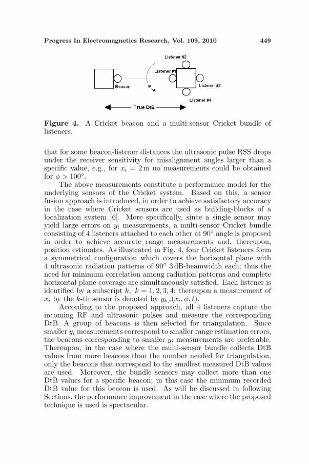
Figure 3. Measured DtB error withrespect to DtB measured at ϕ = 0◦,for Cricket beacon-listener pairs.
where T denotes the observation period. In our analysis herein, weassume that xi and φ remain constant throughout the observationperiod T (static case) so that time averaging is meaningful as a meansof smoothing out noise.
The average yi vs. φ, for various xi is displayed in Fig. 3, for asample size equal to 80. It is observed that there is a monotonicallyincreasing difference between yi and xi as well as between yi andφ. This increasing error is expected, since increasing xi or φ causesdecreasing ultrasonic pulse RSS, which in turn causes higher detectioncircuits’ response time, resulting in an increasing positive error. Theincreasing measurement error may as well be due to other factorsbesides the decrease in the ultrasonic pulse RSS, e.g., environmentalfactors, such as air humidity, pressure and temperature, or hardwarefactors, such as timing and arithmetic quantization, or errors indetecting ultrasonic signals and variable RF-triggered interrupt serviceroutine delays. Other environmental factors in practical applicationsmay include multipath propagation as well.
Furthermore, the ultrasonic transmitter and receiver radiationpatterns of the Cricket sensors are directional and consist of one maindirectional lobe with a 3 dB-beamwidth of about 90◦, while relativeside lobe level remains under 20 dB. Therefore, the RSS as well astransmitter and receiver sensitivity drop along directions different thanφ = 0◦, resulting to monotonically increasing errors. Thereupon,regardless xi, the most reliable DtB measurements are considered to bethe ones corresponding to φ = 0◦. Moreover, by Fig. 3, it is observed
Progress In Electromagnetics Research, Vol. 109, 2010 449
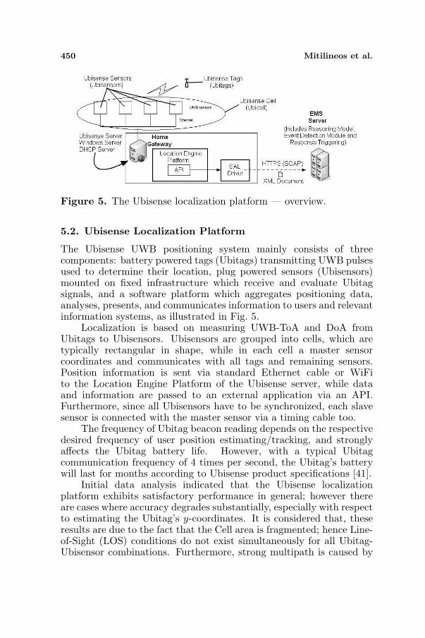
Figure 4. A Cricket beacon and a multi-sensor Cricket bundle oflisteners.
that for some beacon-listener distances the ultrasonic pulse RSS dropsunder the receiver sensitivity for misalignment angles larger than aspecific value, e.g., for xi = 2 m no measurements could be obtainedfor φ > 100◦.
The above measurements constitute a performance model for theunderlying sensors of the Cricket system. Based on this, a sensorfusion approach is introduced, in order to achieve satisfactory accuracyin the case where Cricket sensors are used as building-blocks of alocalization system [6]. More specifically, since a single sensor mayyield large errors on yi measurements, a multi-sensor Cricket bundleconsisting of 4 listeners attached to each other at 90◦ angle is proposedin order to achieve accurate range measurements and, thereupon,position estimates. As illustrated in Fig. 4, four Cricket listeners forma symmetrical configuration which covers the horizontal plane with4 ultrasonic radiation patterns of 90◦ 3 dB-beamwidth each; thus theneed for minimum correlation among radiation patterns and completehorizontal plane coverage are simultaneously satisfied. Each listener isidentified by a subscript k, k = 1, 2, 3, 4; thereupon a measurement ofxi by the k-th sensor is denoted by yk,i(xi, φ, t).
According to the proposed approach, all 4 listeners capture theincoming RF and ultrasonic pulses and measure the correspondingDtB. A group of beacons is then selected for triangulation. Sincesmaller yi measurements correspond to smaller range estimation errors,the beacons corresponding to smaller yi measurements are preferable.Thereupon, in the case where the multi-sensor bundle collects DtBvalues from more beacons than the number needed for triangulation,only the beacons that correspond to the smallest measured DtB valuesare used. Moreover, the bundle sensors may collect more than oneDtB values for a specific beacon; in this case the minimum recordedDtB value for this beacon is used. As will be discussed in followingSections, the performance improvement in the case where the proposedtechnique is used is spectacular.
450 Mitilineos et al.
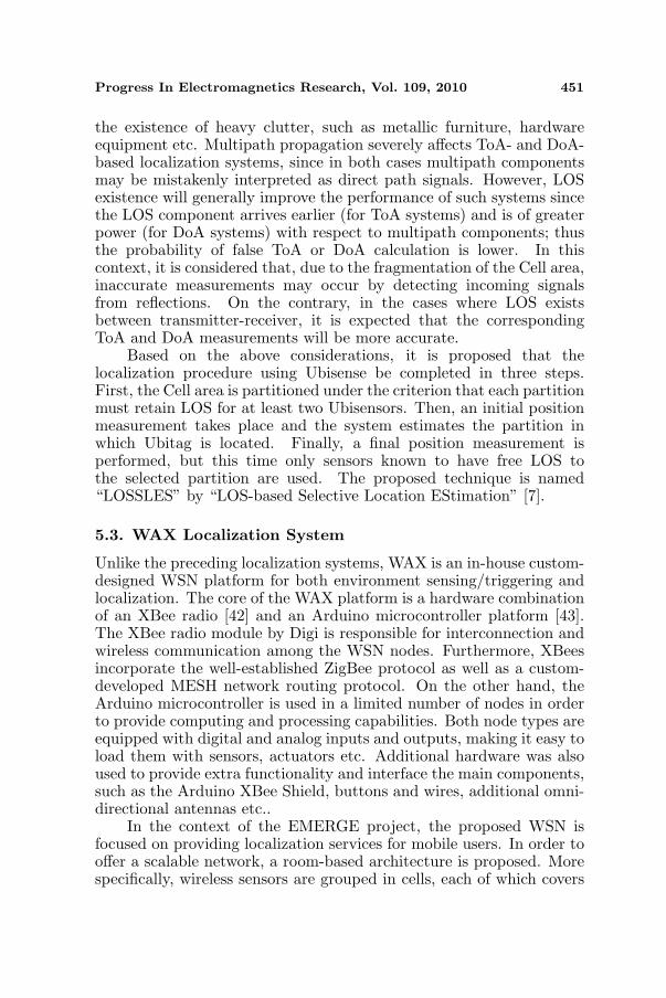
Figure 5. The Ubisense localization platform — overview.
5.2. Ubisense Localization Platform
The Ubisense UWB positioning system mainly consists of threecomponents: battery powered tags (Ubitags) transmitting UWB pulsesused to determine their location, plug powered sensors (Ubisensors)mounted on fixed infrastructure which receive and evaluate Ubitagsignals, and a software platform which aggregates positioning data,analyses, presents, and communicates information to users and relevantinformation systems, as illustrated in Fig. 5.
Localization is based on measuring UWB-ToA and DoA fromUbitags to Ubisensors. Ubisensors are grouped into cells, which aretypically rectangular in shape, while in each cell a master sensorcoordinates and communicates with all tags and remaining sensors.Position information is sent via standard Ethernet cable or WiFito the Location Engine Platform of the Ubisense server, while dataand information are passed to an external application via an API.Furthermore, since all Ubisensors have to be synchronized, each slavesensor is connected with the master sensor via a timing cable too.
The frequency of Ubitag beacon reading depends on the respectivedesired frequency of user position estimating/tracking, and stronglyaffects the Ubitag battery life. However, with a typical Ubitagcommunication frequency of 4 times per second, the Ubitag’s batterywill last for months according to Ubisense product specifications [41].
Initial data analysis indicated that the Ubisense localizationplatform exhibits satisfactory performance in general; however thereare cases where accuracy degrades substantially, especially with respectto estimating the Ubitag’s y-coordinates. It is considered that, theseresults are due to the fact that the Cell area is fragmented; hence Line-of-Sight (LOS) conditions do not exist simultaneously for all Ubitag-Ubisensor combinations. Furthermore, strong multipath is caused by
Progress In Electromagnetics Research, Vol. 109, 2010 451
the existence of heavy clutter, such as metallic furniture, hardwareequipment etc. Multipath propagation severely affects ToA- and DoA-based localization systems, since in both cases multipath componentsmay be mistakenly interpreted as direct path signals. However, LOSexistence will generally improve the performance of such systems sincethe LOS component arrives earlier (for ToA systems) and is of greaterpower (for DoA systems) with respect to multipath components; thusthe probability of false ToA or DoA calculation is lower. In thiscontext, it is considered that, due to the fragmentation of the Cell area,inaccurate measurements may occur by detecting incoming signalsfrom reflections. On the contrary, in the cases where LOS existsbetween transmitter-receiver, it is expected that the correspondingToA and DoA measurements will be more accurate.
Based on the above considerations, it is proposed that thelocalization procedure using Ubisense be completed in three steps.First, the Cell area is partitioned under the criterion that each partitionmust retain LOS for at least two Ubisensors. Then, an initial positionmeasurement takes place and the system estimates the partition inwhich Ubitag is located. Finally, a final position measurement isperformed, but this time only sensors known to have free LOS tothe selected partition are used. The proposed technique is named“LOSSLES” by “LOS-based Selective Location EStimation” [7].
5.3. WAX Localization System
Unlike the preceding localization systems, WAX is an in-house custom-designed WSN platform for both environment sensing/triggering andlocalization. The core of the WAX platform is a hardware combinationof an XBee radio [42] and an Arduino microcontroller platform [43].The XBee radio module by Digi is responsible for interconnection andwireless communication among the WSN nodes. Furthermore, XBeesincorporate the well-established ZigBee protocol as well as a custom-developed MESH network routing protocol. On the other hand, theArduino microcontroller is used in a limited number of nodes in orderto provide computing and processing capabilities. Both node types areequipped with digital and analog inputs and outputs, making it easy toload them with sensors, actuators etc. Additional hardware was alsoused to provide extra functionality and interface the main components,such as the Arduino XBee Shield, buttons and wires, additional omni-directional antennas etc..
In the context of the EMERGE project, the proposed WSN isfocused on providing localization services for mobile users. In order tooffer a scalable network, a room-based architecture is proposed. Morespecifically, wireless sensors are grouped in cells, each of which covers
452 Mitilineos et al.
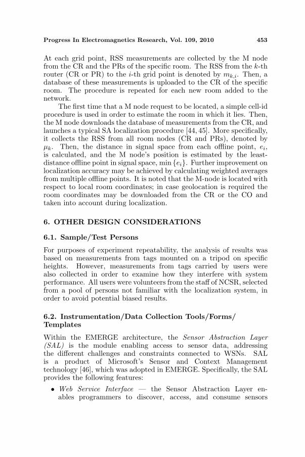
Figure 6. Proposed WAX architecture. Figure 7. RSS-SAtechnique used in WAX.
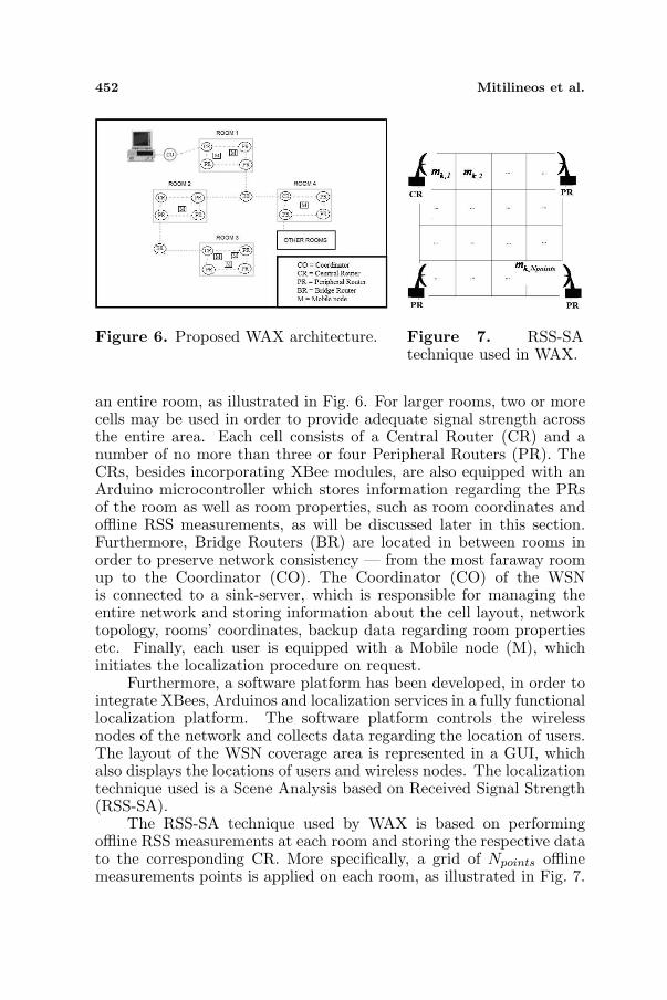
an entire room, as illustrated in Fig. 6. For larger rooms, two or morecells may be used in order to provide adequate signal strength acrossthe entire area. Each cell consists of a Central Router (CR) and anumber of no more than three or four Peripheral Routers (PR). TheCRs, besides incorporating XBee modules, are also equipped with anArduino microcontroller which stores information regarding the PRsof the room as well as room properties, such as room coordinates andoffline RSS measurements, as will be discussed later in this section.Furthermore, Bridge Routers (BR) are located in between rooms inorder to preserve network consistency — from the most faraway roomup to the Coordinator (CO). The Coordinator (CO) of the WSNis connected to a sink-server, which is responsible for managing theentire network and storing information about the cell layout, networktopology, rooms’ coordinates, backup data regarding room propertiesetc. Finally, each user is equipped with a Mobile node (M), whichinitiates the localization procedure on request.
Furthermore, a software platform has been developed, in order tointegrate XBees, Arduinos and localization services in a fully functionallocalization platform. The software platform controls the wirelessnodes of the network and collects data regarding the location of users.The layout of the WSN coverage area is represented in a GUI, whichalso displays the locations of users and wireless nodes. The localizationtechnique used is a Scene Analysis based on Received Signal Strength(RSS-SA).
The RSS-SA technique used by WAX is based on performingoffline RSS measurements at each room and storing the respective datato the corresponding CR. More specifically, a grid of Npoints offlinemeasurements points is applied on each room, as illustrated in Fig. 7.
Progress In Electromagnetics Research, Vol. 109, 2010 453
At each grid point, RSS measurements are collected by the M nodefrom the CR and the PRs of the specific room. The RSS from the k-throuter (CR or PR) to the i-th grid point is denoted by mk,i. Then, adatabase of these measurements is uploaded to the CR of the specificroom. The procedure is repeated for each new room added to thenetwork.
The first time that a M node request to be located, a simple cell-idprocedure is used in order to estimate the room in which it lies. Then,the M node downloads the database of measurements from the CR, andlaunches a typical SA localization procedure [44, 45]. More specifically,it collects the RSS from all room nodes (CR and PRs), denoted byµk. Then, the distance in signal space from each offline point, ei,is calculated, and the M node’s position is estimated by the least-distance offline point in signal space, min {ei}. Further improvement onlocalization accuracy may be achieved by calculating weighted averagesfrom multiple offline points. It is noted that the M-node is located withrespect to local room coordinates; in case geolocation is required theroom coordinates may be downloaded from the CR or the CO andtaken into account during localization.
6. OTHER DESIGN CONSIDERATIONS
6.1. Sample/Test Persons
For purposes of experiment repeatability, the analysis of results wasbased on measurements from tags mounted on a tripod on specificheights. However, measurements from tags carried by users werealso collected in order to examine how they interfere with systemperformance. All users were volunteers from the staff of NCSR, selectedfrom a pool of persons not familiar with the localization system, inorder to avoid potential biased results.
6.2. Instrumentation/Data Collection Tools/Forms/Templates
Within the EMERGE architecture, the Sensor Abstraction Layer(SAL) is the module enabling access to sensor data, addressingthe different challenges and constraints connected to WSNs. SALis a product of Microsoft’s Sensor and Context Managementtechnology [46], which was adopted in EMERGE. Specifically, the SALprovides the following features:
• Web Service Interface — the Sensor Abstraction Layer en-ables programmers to discover, access, and consume sensors
454 Mitilineos et al.
data through standard web services protocols (WS-MetaData Ex-change, WS-Eventing, WS-Discovery). Those protocols are opento non. NET applications compliant to the WS Specification [47–49].
• Sensor Abstraction — the sensor specific details (e.g., commu-nication technology, protocols etc.) are hidden from applicationprogrammers in order to allow for an easier integration of sensorsinto software applications and a flexible use of sensor inside an ap-plication. Thus, in the case where different sensor hardware of thesame class is used (e.g., temperature sensor), it is not necessaryto modify the application. In other words, the same applicationis able to use sensors from different vendors interchangeably.
• Different Sensor Access strategies: Pull, Push, Stream —depending on the sensor data, different access idioms for the dataare provided. Reading a temperature value is efficiently done bypulling the data from the sensor. Exceeding a temperature limitcan easily be signaled to the application using events. In this casethe application does not need to wait for the event to happen, butgets a notification when it occurs. An application focused on atime series of temperature values is best served by a streamingapproach.
• Targeting heterogeneous sensor technologies — the SAL platformallows the interoperability with different types of sensor platformssuch as TinyOS, BSN Nodes, and many others by offering theoption to add plug-in modules for those platforms.
• Extensible — the sensor field is rapidly changing. New sensornodes, sensor values, sensor applications, networking technologies,communication protocols will be created. By providing a modularapproach for sensor plug-in, the SAL architecture is extendabletowards these changes.
• Distribution of Computation — computation such as situationrecognition, sensor data filtering, or monitoring can be distributedbetween all components of the sensor network (sensor nodes,sensor gateways and applications). This is important in thecontext of limited resources. E.g., computing activity data fromraw sensor data on the sensor node might be more power efficientthan sending the whole video stream constantly to another node.
• Support of IP and Non-IP based communication technologies— sensor networks are using different networking technologies,which are not necessarily IP based. Providing IP communicationfacilitates platform and application implementation.
Progress In Electromagnetics Research, Vol. 109, 2010 455
7. PREPARATION — EXPERIMENT RUN
7.1. Preparation
7.1.1. Cricket Localization System
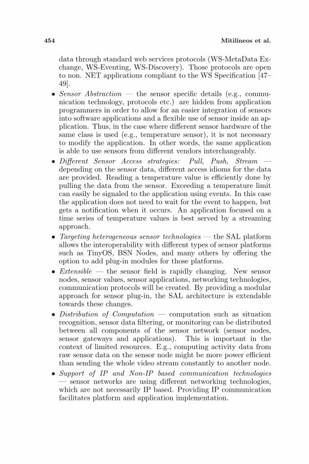
The proposed Cricket-based sensor fusion and localization algorithmwas experimentally evaluated via measurements conducted within thepremises of the Institute of Informatics and Telecommunications (IIT)of the National Center for Scientific Research (NCSR) “Demokritos”,Athens, Greece. A total of 6 Cricket beacons were attached on theceiling of a typical office room, at coordinates as shown in Fig. 8and facing towards the floor, while the room area is ACricket =6.5 × 5.1m2 (length/width). Then, the Cricket localization systemand the proposed fusion technique performance were evaluated viasample test measurements at predetermined listener locations withinthe specified area.
7.1.2. Ubisense Localization Platform
The LOSSLES technique for accurate indoor localization using theUbisense platform was experimentally evaluated via measurementsconducted within the IIT, NCSR “Demokritos”. This time, themeasurements area included a typical office room, a meeting room
Figure 8. Layout of the measurements area for the Cricket localizationsystem.
456 Mitilineos et al.
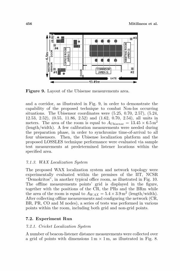
Figure 9. Layout of the Ubisense measurements area.
and a corridor, as illustrated in Fig. 9, in order to demonstrate thecapability of the proposed technique to combat Non-los occurringsituations. The Ubisensor coordinates were (5.25, 0.70, 2.57), (5.24,12.53, 2.52), (0.55, 11.86, 2.52) and (1.62, 0.70, 2.54), all units inmeters. The area of the room is equal to AUbisense = 13.45 × 6.5m2
(length/width). A few calibration measurements were needed duringthe preparation phase, in order to synchronize time-of-arrival to allfour ubisensors. Then, the Ubisense localization platform and theproposed LOSSLES technique performance were evaluated via sampletest measurements at predetermined listener locations within thespecified area.
7.1.3. WAX Localization System
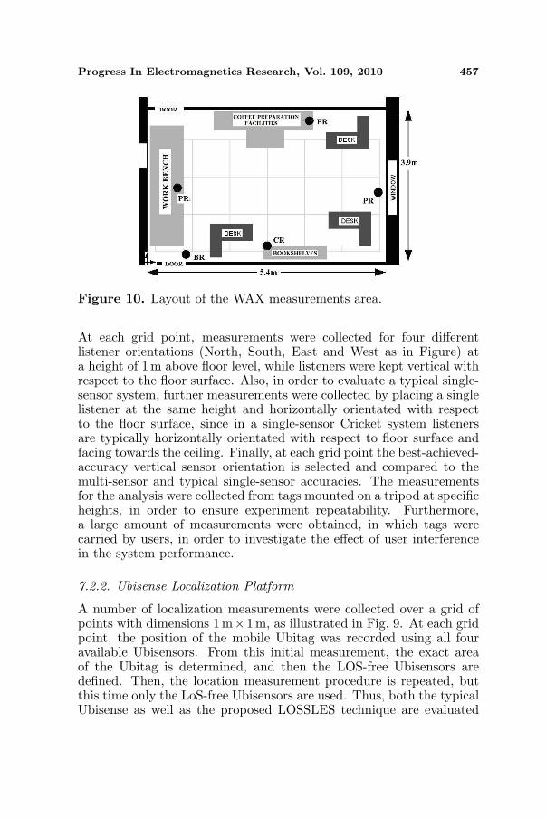
The proposed WAX localization system and network topology wereexperimentally evaluated within the premises of the IIT, NCSR“Demokritos”, in another typical office room, as illustrated in Fig. 10.The offline measurements points’ grid is displayed in the figure,together with the positions of the CR, the PRs and the BRm whilethe area of the room is equal to AWAX = 5.4× 3.9m2 (length/width).After collecting offline measurements and configuring the network (CR,BR, PR, CO and M nodes), a series of tests was performed in variouspoints within the room, including both grid and non-grid points.
7.2. Experiment Run
7.2.1. Cricket Localization System
A number of beacon-listener distance measurements were collected overa grid of points with dimensions 1m × 1m, as illustrated in Fig. 8.
Progress In Electromagnetics Research, Vol. 109, 2010 457
Figure 10. Layout of the WAX measurements area.
At each grid point, measurements were collected for four differentlistener orientations (North, South, East and West as in Figure) ata height of 1m above floor level, while listeners were kept vertical withrespect to the floor surface. Also, in order to evaluate a typical single-sensor system, further measurements were collected by placing a singlelistener at the same height and horizontally orientated with respectto the floor surface, since in a single-sensor Cricket system listenersare typically horizontally orientated with respect to floor surface andfacing towards the ceiling. Finally, at each grid point the best-achieved-accuracy vertical sensor orientation is selected and compared to themulti-sensor and typical single-sensor accuracies. The measurementsfor the analysis were collected from tags mounted on a tripod at specificheights, in order to ensure experiment repeatability. Furthermore,a large amount of measurements were obtained, in which tags werecarried by users, in order to investigate the effect of user interferencein the system performance.
7.2.2. Ubisense Localization Platform
A number of localization measurements were collected over a grid ofpoints with dimensions 1 m×1m, as illustrated in Fig. 9. At each gridpoint, the position of the mobile Ubitag was recorded using all fouravailable Ubisensors. From this initial measurement, the exact areaof the Ubitag is determined, and then the LOS-free Ubisensors aredefined. Then, the location measurement procedure is repeated, butthis time only the LoS-free Ubisensors are used. Thus, both the typicalUbisense as well as the proposed LOSSLES technique are evaluated
458 Mitilineos et al.
and compared to one another, within the same environment and underthe same data set. Again, the measurements for the analysis werecollected from tags mounted on a tripod at specific heights, in orderto ensure experiment repeatability. Furthermore, a large amount ofmeasurements were obtained, in which tags were carried by users,in order to investigate the effect of user interference in the systemperformance.
7.2.3. WAX Localization System
The proposed WAX system was evaluated in a series of grid and non-grid points during online localization measurements. More specifically,we evaluated 5 grid and 5 non-grid points; at each point the positionof the M node was calculated 50 times in order to collect accuratestatistics regarding the behavior of the proposed localization system.As expected, the achieved accuracy was affected by the selection of gridand non-grid points, as will be discussed later in the results Section.Again, the measurements for the analysis were collected from tagsmounted on a tripod at specific heights, in order to ensure experimentrepeatability. Furthermore, a large amount of measurements wereobtained, in which tags were carried by users, in order to investigatethe effect of user interference in the system performance.
8. RESULTS AND ANALYSIS
8.1. Cricket Localization System
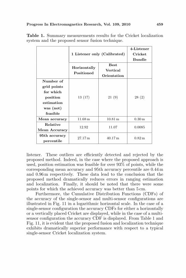
Based on distance measurements from various beacons described inSection 7.2.1, the multi-sensor bundle’s as well as the single-sensorlistener’s position were calculated via triangulation. It was foundthat, in the case where the single-sensor listener is used, there arenumerous grid points for which no position estimate may be calculated,because no ultrasonic pulses from an adequate number of beacons fortriangulation were detected. On the other hand, in the case where theproposed multi-sensor Cricket bundle and fusion algorithm are used,the number of points for which no position estimate may be calculatedis drastically reduced, as tabulated in the third row of Table 1.Regarding the grid points for which position estimation was feasible,Table 1 demonstrates the respective mean accuracy and the 95thaccuracy percentile. It is noted that, with the single-sensor approach,position estimation was feasible for less than 45% of points, while themean accuracy and 95th percentile for these points was 11.68 m and27.17m respectively. These uncommonly large values appear due tothe large number of outlier DtB measurements when using a single
Progress In Electromagnetics Research, Vol. 109, 2010 459
Table 1. Summary measurements results for the Cricket localizationsystem and the proposed sensor fusion technique.
1 Listener only (Calibrated)
4-Listener
Cricket
Bundle
Horizontally
Positioned
Best
Vertical
Orientation
Number of
grid points
for which
position
estimation
was (not)
feasible
13 (17) 21 (9) 28 (2)
Mean accuracy 11.68m 10.81m 0.30m
Relative
Mean Accuracy12.92 11.07 0.0085
95th accuracy
percentile27.17m 40.17m 0.82m
listener. These outliers are efficiently detected and rejected by theproposed method. Indeed, in the case where the proposed approach isused, position estimation was feasible for over 93% of points, while thecorresponding mean accuracy and 95th accuracy percentile are 0.44 mand 0.96 m respectively. These data lead to the conclusion that theproposed method dramatically reduces errors in ranging estimationand localization. Finally, it should be noted that there were somepoints for which the achieved accuracy was better than 5 cm.
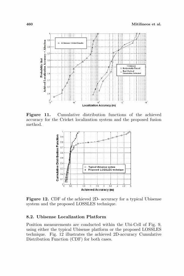
Furthermore, the Cumulative Distribution Functions (CDFs) ofthe accuracy of the single-sensor and multi-sensor configurations areillustrated in Fig. 11 in a logarithmic horizontal scale. In the case of asingle-sensor configuration the accuracy CDFs for either a horizontallyor a vertically placed Cricket are displayed, while in the case of a multi-sensor configuration the accuracy CDF is displayed. From Table 1 andFig. 11, it is evident that the proposed fusion and localization techniqueexhibits dramatically superior performance with respect to a typicalsingle-sensor Cricket localization system.
460 Mitilineos et al.
Figure 11. Cumulative distribution functions of the achievedaccuracy for the Cricket localization system and the proposed fusionmethod.
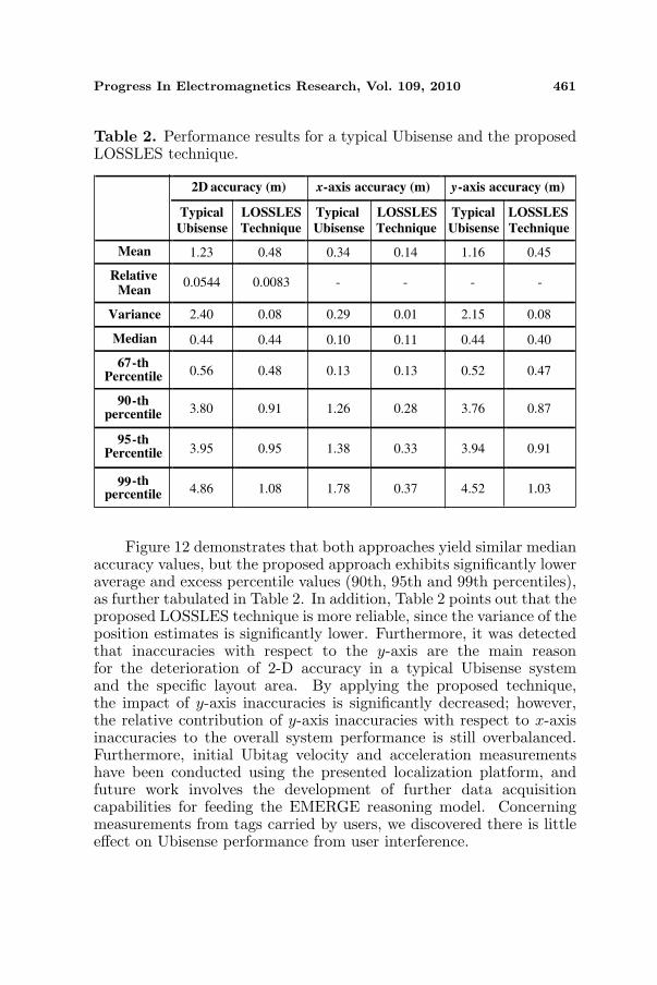
Figure 12. CDF of the achieved 2D- accuracy for a typical Ubisensesystem and the proposed LOSSLES technique.
8.2. Ubisense Localization Platform
Position measurements are conducted within the Ubi-Cell of Fig. 9,using either the typical Ubisense platform or the proposed LOSSLEStechnique. Fig. 12 illustrates the achieved 2D-accuracy CumulativeDistribution Function (CDF) for both cases.
Progress In Electromagnetics Research, Vol. 109, 2010 461
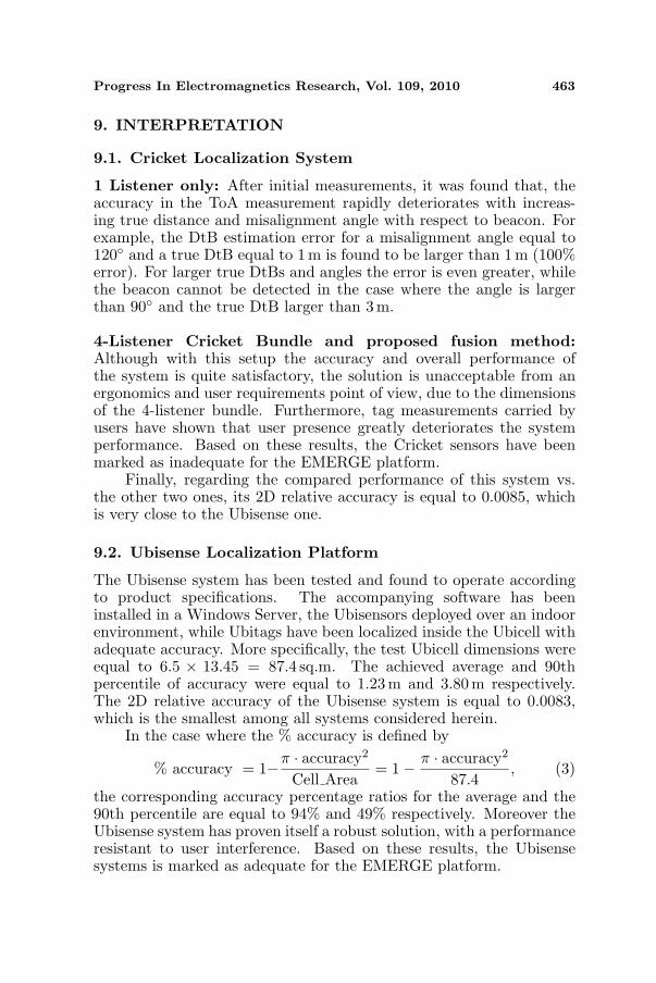
Table 2. Performance results for a typical Ubisense and the proposedLOSSLES technique.
2D accuracy (m) x-axis accuracy (m) y-axis accuracy (m)
Typical
Ubisense
LOSSLES
Technique
Typical
Ubisense
LOSSLES
Technique
Typical
Ubisense
LOSSLES
Technique
Mean 1.23 0.48 0.34 0.14 1.16 0.45
Relative Mean
0.0544 0.0083 - - - -
Variance 2.40 0.08 0.29 0.01 2.15 0.08
Median 0.44 0.44 0.10 0.11 0.44 0.40
67-th Percentile 0.56 0.48 0.13 0.13 0.52 0.47
90-th percentile 3.80 0.91 1.26 0.28 3.76 0.87
95-th Percentile 3.95 0.95 1.38 0.33 3.94 0.91
99-th percentile 4.86 1.08 1.78 0.37 4.52 1.03
Figure 12 demonstrates that both approaches yield similar medianaccuracy values, but the proposed approach exhibits significantly loweraverage and excess percentile values (90th, 95th and 99th percentiles),as further tabulated in Table 2. In addition, Table 2 points out that theproposed LOSSLES technique is more reliable, since the variance of theposition estimates is significantly lower. Furthermore, it was detectedthat inaccuracies with respect to the y-axis are the main reasonfor the deterioration of 2-D accuracy in a typical Ubisense systemand the specific layout area. By applying the proposed technique,the impact of y-axis inaccuracies is significantly decreased; however,the relative contribution of y-axis inaccuracies with respect to x-axisinaccuracies to the overall system performance is still overbalanced.Furthermore, initial Ubitag velocity and acceleration measurementshave been conducted using the presented localization platform, andfuture work involves the development of further data acquisitioncapabilities for feeding the EMERGE reasoning model. Concerningmeasurements from tags carried by users, we discovered there is littleeffect on Ubisense performance from user interference.
462 Mitilineos et al.
8.3. WAX Localization System
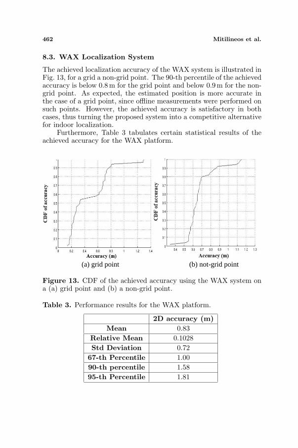
The achieved localization accuracy of the WAX system is illustrated inFig. 13, for a grid a non-grid point. The 90-th percentile of the achievedaccuracy is below 0.8 m for the grid point and below 0.9m for the non-grid point. As expected, the estimated position is more accurate inthe case of a grid point, since offline measurements were performed onsuch points. However, the achieved accuracy is satisfactory in bothcases, thus turning the proposed system into a competitive alternativefor indoor localization.
Furthermore, Table 3 tabulates certain statistical results of theachieved accuracy for the WAX platform.
(a) grid point (b) not-grid point
Figure 13. CDF of the achieved accuracy using the WAX system ona (a) grid point and (b) a non-grid point.
Table 3. Performance results for the WAX platform.
2D accuracy (m)Mean 0.83
Relative Mean 0.1028Std Deviation 0.72
67-th Percentile 1.0090-th percentile 1.5895-th Percentile 1.81
Progress In Electromagnetics Research, Vol. 109, 2010 463
9. INTERPRETATION
9.1. Cricket Localization System
1 Listener only: After initial measurements, it was found that, theaccuracy in the ToA measurement rapidly deteriorates with increas-ing true distance and misalignment angle with respect to beacon. Forexample, the DtB estimation error for a misalignment angle equal to120◦ and a true DtB equal to 1m is found to be larger than 1 m (100%error). For larger true DtBs and angles the error is even greater, whilethe beacon cannot be detected in the case where the angle is largerthan 90◦ and the true DtB larger than 3 m.
4-Listener Cricket Bundle and proposed fusion method:Although with this setup the accuracy and overall performance ofthe system is quite satisfactory, the solution is unacceptable from anergonomics and user requirements point of view, due to the dimensionsof the 4-listener bundle. Furthermore, tag measurements carried byusers have shown that user presence greatly deteriorates the systemperformance. Based on these results, the Cricket sensors have beenmarked as inadequate for the EMERGE platform.
Finally, regarding the compared performance of this system vs.the other two ones, its 2D relative accuracy is equal to 0.0085, whichis very close to the Ubisense one.
9.2. Ubisense Localization Platform
The Ubisense system has been tested and found to operate accordingto product specifications. The accompanying software has beeninstalled in a Windows Server, the Ubisensors deployed over an indoorenvironment, while Ubitags have been localized inside the Ubicell withadequate accuracy. More specifically, the test Ubicell dimensions wereequal to 6.5 × 13.45 = 87.4 sq.m. The achieved average and 90thpercentile of accuracy were equal to 1.23 m and 3.80m respectively.The 2D relative accuracy of the Ubisense system is equal to 0.0083,which is the smallest among all systems considered herein.
In the case where the % accuracy is defined by
% accuracy = 1−π · accuracy2
Cell Area= 1− π · accuracy2
87.4, (3)
the corresponding accuracy percentage ratios for the average and the90th percentile are equal to 94% and 49% respectively. Moreover theUbisense system has proven itself a robust solution, with a performanceresistant to user interference. Based on these results, the Ubisensesystems is marked as adequate for the EMERGE platform.
464 Mitilineos et al.
Furthermore, in the case where the proposed LOSSLES techniqueis used, the corresponding average and percentile of accuracy drop to0.48m and 0.91 m respectively. Thus, the corresponding percentageaccuracy ratios become 99% and 97% respectively, thus demonstratingthe applicability of the proposed technique.
9.3. WAX Localization System
The WAX system was successfully tested in a typical indoor officeroom, and the achieved accuracy was found to be below 1 m in all cases.For larger spaces with more rooms, it is expected that the achievedaccuracy will remain in below 1 m levels, since location estimationis performed at room level and is not affected by the network size.The achieved accuracy is comparable to the Ubisense one. On theother hand, WAX mobile nodes are still heavier and bulkier than theUbisense ones, but lighter and more compact compared to the Cricketones. We are currently working on developing a WAX mobile nodethat will be lighter, more compact and more ergonomic. Finally, the 2Drelative accuracy of the WAX platform is equal to 0.1028, which is quitelarge compared to the Ubisense and Cricket ones. However, it is notedthat the WAX platform is highly scalable, meaning that the absoluteaccuracy will remain relatively constant for larger environments (withthe cost of extra sensors).
Furthermore, the WAX system is resilient in user presence,provided offline measurements are performed with a user carryingthe M-node tag. Also, the proposed WAX solution is the onlyamong the three presented that also offers extended sensing and actingcapabilities, as it is based on a microntroller and ZigBee radio hardwarecore. Therefore, it is marked as adequate for the EMERGE platform,but also considered to be the most competitive solution, since itoffers scalability and expandability beyond the scope of the EMERGEproject.
9.4. Threats to Validity
Threats that might have an impact on the validity of the results arediscussed in this section.
Construct/Environment validity: A possible threat is ignoringthe interference of specific environment/construct elements, if theexperiment is run in an area convenient for system operation, missingpossible elements found in the actual end- user environment. The labroom used for setting up the experiments is an actual active office inthe NCSR premises. Namely, all sorts of materials (e.g., wood, metal,plastic, glass) and interfering equipment, objects and persons are found
Progress In Electromagnetics Research, Vol. 109, 2010 465
in this room. Therefore results can be safely assumed to be valid acrossmany types of environments.
Internal validity: Selection: Volunteers for the experiment wereused from NCSR staff. This is seen as a threat because theymight be more aware of technical issues than the average population.However, having this threat in mind, the people that were chosenhad totally different domains of expertise and were unfamiliar withrelated localization systems. Moreover, the use of a tripod for user-freemeasurements provided with useful information regarding a repeatablelocalization process. No other internal threat was identified as peoplesimply carry around the beacons, not interacting with the system atany other point.
External validity: Although the setting was not in an actual end-user environment and the test users did not belong to the addressedpopulation, it is claimed that the results can be generalized. Regardingthe former, environment validity was justified above within this section.As far as end-users are concerned, their participation is considered inthis system passive, with the minimum requirement to carry/wear thebeacon on them. As far as user interference with the measurementsis concerned, this was actually considered a priori as an experimentparameter under examination, ergo not a threat for the experiment.
Conclusion validity: Reliability of measures and reliability ofdata processing, quality of data: calibration of measurements in thepreparation phase of the experiment as well as use of a differentset of tags per experiment run, ensure reliable measurement andprocessing as well as high quality of data. The use of tripod formeasurements in our analysis ensured experiment repeatability andvalidity of conclusions.
10. REAL-WORLD DEPLOYMENT CONSIDERATIONS
In this section, main real-world deployment considerations arepresented for the experimental platforms used.
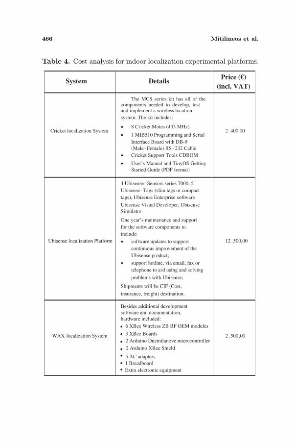
In Table 4, the cost for each platform setup is calculated, givenalso documentation, support and software provided upon purchase ofrelated products. In the cost calculated there, is also a significantoverhead for hardware, software and support needed for development.This extra cost will not apply in the case of mass production. Inthis case, it is estimated that Cricket and WAX systems wouldbe around 500€ per room for one user while the correspondingcost for Ubisense would be around 5000€. It is evident that, theUbisense Localization Platform has a relatively extreme high costcompared to the other platforms, prohibiting the platform from being
466 Mitilineos et al.
Table 4. Cost analysis for indoor localization experimental platforms.
System
DetailsPrice (€)
(incl. VAT)
Cricket localization System
The MCS series kit has all of the components needed to develop, test and implement a wireless location
system. The kit includes:
• 8 Cricket Motes (433 MHz)
• 1 MIB510 Programming and Serial
Interface Board with DB-9
(Male -Female) RS -232 Cable
• Cricket Support Tools CDROM
• User’s Manual and TinyOS Getting
Started Guide (PDF format)
2 .400,00
Ubisense localization Platform
4 Ubisense -Sensors series 7000, 5
Ubisense -Tags (slim tags or compact
tags), Ubisense Enterprise software
Ubisense Visual Developer, Ubisense
Simulator
One year’s maintenance and support
for the software components to
include:
• software updates to support
continuous improvement of the
Ubisense product;
• support hotline, via email, fax or
telephone to aid using and solving
problems with Ubisense;
Shipments will be CIF (Cost,
insurance, freight) destination.
12 .500,00
WAX localization System
Besides additional development
software and documentation,
2 .500,00
hardware included:
•
•
•
•
•
•
•
6 XBee Wireless ZB RF OEM modules
3 XBee Boards
2 Arduino Duemilanove microcontroller
2 Arduino XBee Shield
5 AC adapters
1 Breadboard
Extra electronic equipment
Progress In Electromagnetics Research, Vol. 109, 2010 467
suitable for home applications and users. However, in a professionalenvironment, organizations could consider such a cost when accurateindoor localization is essential. The other platforms offer a solutionwith a significantly lower budget, however the cost could still beconsidered as high for most home users. As an overall conclusionregarding cost, inexpensive indoor localization is still a researchchallenge.
Besides cost, real-world concerns for deploying each proposedsolution also include the ergonomics of the sensors carried/worn by theuser as well as the intrusiveness of the corresponding infrastructure.
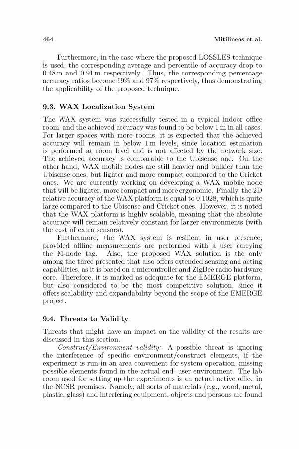
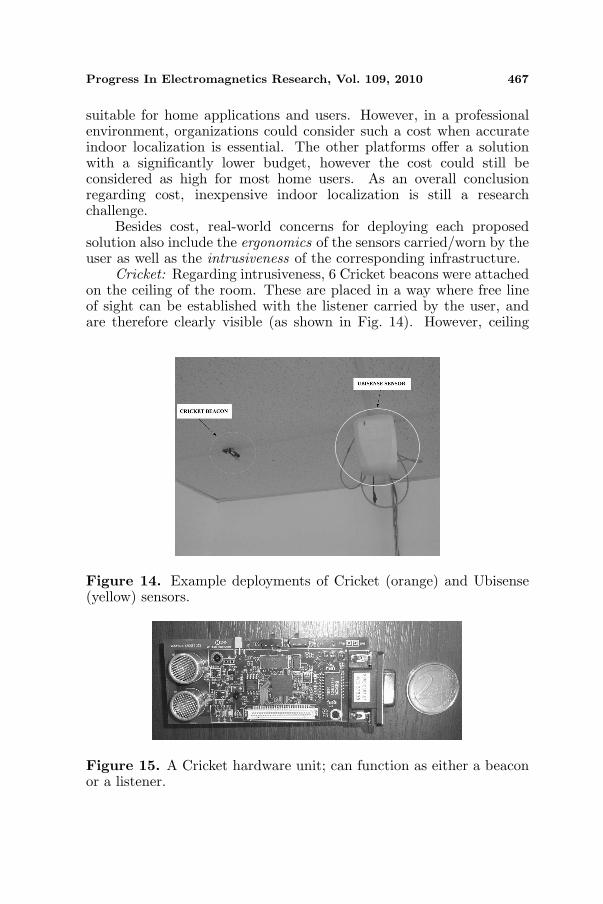
Cricket: Regarding intrusiveness, 6 Cricket beacons were attachedon the ceiling of the room. These are placed in a way where free lineof sight can be established with the listener carried by the user, andare therefore clearly visible (as shown in Fig. 14). However, ceiling
Figure 14. Example deployments of Cricket (orange) and Ubisense(yellow) sensors.
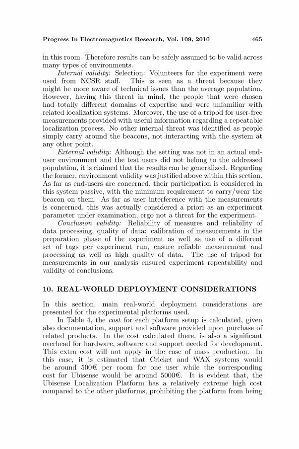
Figure 15. A Cricket hardware unit; can function as either a beaconor a listener.
468 Mitilineos et al.
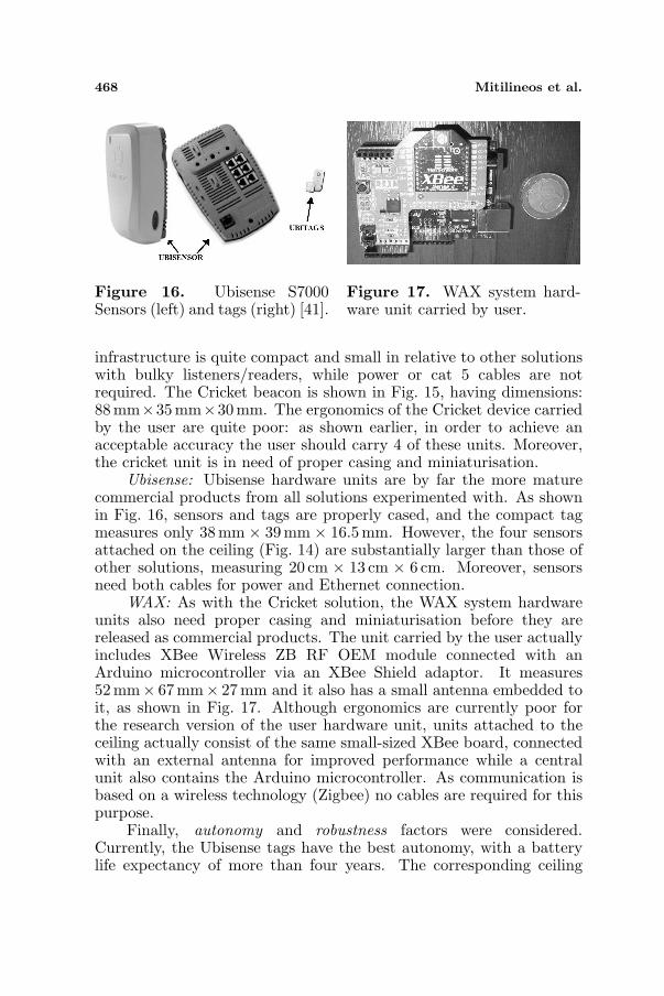
Figure 16. Ubisense S7000Sensors (left) and tags (right) [41].
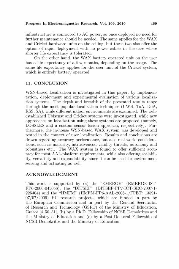
Figure 17. WAX system hard-ware unit carried by user.
infrastructure is quite compact and small in relative to other solutionswith bulky listeners/readers, while power or cat 5 cables are notrequired. The Cricket beacon is shown in Fig. 15, having dimensions:88mm×35mm×30mm. The ergonomics of the Cricket device carriedby the user are quite poor: as shown earlier, in order to achieve anacceptable accuracy the user should carry 4 of these units. Moreover,the cricket unit is in need of proper casing and miniaturisation.
Ubisense: Ubisense hardware units are by far the more maturecommercial products from all solutions experimented with. As shownin Fig. 16, sensors and tags are properly cased, and the compact tagmeasures only 38 mm × 39 mm × 16.5mm. However, the four sensorsattached on the ceiling (Fig. 14) are substantially larger than those ofother solutions, measuring 20 cm × 13 cm × 6 cm. Moreover, sensorsneed both cables for power and Ethernet connection.
WAX: As with the Cricket solution, the WAX system hardwareunits also need proper casing and miniaturisation before they arereleased as commercial products. The unit carried by the user actuallyincludes XBee Wireless ZB RF OEM module connected with anArduino microcontroller via an XBee Shield adaptor. It measures52mm× 67mm× 27 mm and it also has a small antenna embedded toit, as shown in Fig. 17. Although ergonomics are currently poor forthe research version of the user hardware unit, units attached to theceiling actually consist of the same small-sized XBee board, connectedwith an external antenna for improved performance while a centralunit also contains the Arduino microcontroller. As communication isbased on a wireless technology (Zigbee) no cables are required for thispurpose.
Finally, autonomy and robustness factors were considered.Currently, the Ubisense tags have the best autonomy, with a batterylife expectancy of more than four years. The corresponding ceiling
Progress In Electromagnetics Research, Vol. 109, 2010 469
infrastructure is connected to AC power, so once deployed no need forfurther maintenance should be needed. The same applies for the WAXand Cricket hardware units on the ceiling, but these two also offer theoption of rapid deployment with no power cables in the case whereshorter life expectancy is tolerated.
On the other hand, the WAX battery operated unit on the userhas a life expectancy of a few months, depending on the usage. Thesame life expectancy applies for the user unit of the Cricket system,which is entirely battery operated.
11. CONCLUSION
WSN-based localization is investigated in this paper, by implemen-tation, deployment and experimental evaluation of various localiza-tion systems. The depth and breadth of the presented results rangethrough the most popular localization techniques (UWB, ToA, DoA,RSS, SA), while different indoor environments are examined. The well-established Ubisense and Cricket systems were investigated, while newapproaches on localization using these systems are proposed (namely,LOSSLES and a custom sensor fusion approach, respectively). Fur-thermore, the in-house WSN-based WAX system was developed andtested in the context of user localization. Results and conclusions aredrawn regarding accuracy performance, but also real-world considera-tions, such as maturity, intrusiveness, validity threats, autonomy androbustness etc.. The WAX system is found to offer sufficient accu-racy for most AAL-platform requirements, while also offering scalabil-ity, versatility and expandability, since it can be used for environmentsensing and actuating as well.
ACKNOWLEDGMENT
This work is supported by (a) the “EMERGE” (EMERGE-IST-FP6-2006-045056), the “DITSEF” (DITSEF-FP7-ICT-SEC-2007-1-225404) and the “HMFM” (HMFM-FP6-AAL-2008-1/ΓΓET: 13591-07/07/2009) EU research projects, which are funded in part bythe European Commission and in part by the General Secretariatof Research and Technology (GSRT) of the Ministry of Education,Greece [4, 50–51], (b) by a Ph.D. Fellowship of NCSR Demokritos andthe Ministry of Education and (c) by a Post-Doctoral Fellowship ofNCSR Demokritos and the Ministry of Education.
470 Mitilineos et al.
REFERENCES
1. Raghavendra, C. N., K. M. Sivalingham, and T. Znati, WirelessSensor Networks, Springer Science and Business Media Inc., NewYork, USA, 2004.
2. Lewis, F. L., “Wireless sensor networks,” Smart Environments:Technologies, Protocols and Applications, John Wiley and Sons,New York, USA, 2004.
3. Callaway, E. H., Wireless Sensor Networks — Architectures andProtocols, CRC Press, Boca Raton, FL, USA, 2004.
4. Emergency Monitoring and Prevention — “EMERGE”,(EMERGE-IST-FP6-2006-045056), researh project funded by theEU under IST-2005-2.6.2, http://www.emerge-project.eu/vision/index.html.
5. Mitilineos, S. A., G. K. Roumeliotis, K. S. Mougiakos,C. N. Capsalis, and S. C. A. Thomopoulos, “Positioning accuracyenhancement using localization error modeling,” Proceedings ofthe 10th IEEE Symposium on a World of Wireless Mobile andMultimedia Communications, 1–5, Kos, Greece, Jun. 15–19, 2009.
6. Mitilineos, S. A., N. D. Argyreas, and S. C. A. Thomopoulos, “Anear-optimal low complexity sensor fusion technique for accuratelocalization based on ultrasound time of arrival measurementsfrom low-quality sensors,” SPIE Defense Securiy and Sensing —Proceedings of the XVIII Conference on Signal Processing, SensorFusion, and Target Recognition, 1–5, Orlando, FL, USA, Apr. 13–17, 2009.
7. Mitilineos, S. A., N. D. Argyreas, E. T. Makri, D. M. Kyriazanos,and S. C. Thomopoulos, “An indoor localization platform forambient assisted living using UWB,” Proceedings of the 6thInternational Conference on Advances in Mobile Computing andMultimedia, (WAS-ACM MoMM 2008), 178–182, Linz, Austria,Nov. 24–26, 2008.
8. Parisek, Z., Z. Ruzsa, and G. Gordos, “Mathematical algorithmsof an indoor ultrasonic localization system,” InfocommunicationsJournal, Vol. LXIV, No. 4, 30–36, 2009.
9. Massacci, F., V. H. Nguyen, and A. Saidane, “No purpose, nodata: Goal-oriented access control for ambient assisted living,”Proceedings of the First ACM Workshop on Security and Privacyin Medical and Home-care Systems, 53–58, Chicago, IL, USA,2009.
10. Holzinger, A., K. Schaupp, and W. Eder-Halbedl, “Aninvestigation on acceptance of ubiquitous devices for the elderly
Progress In Electromagnetics Research, Vol. 109, 2010 471
in an geriatric hospital environment: Using the example of persontracking,” 11th International Conference on Computers HelpingPeople with Special Needs, K. Miesenberger et al. (eds.), 22–29,Springer, Lecture Notes in Computer Science (LNCS 5105), 2008.
11. Holzinger, A., G. Searle, T. Kleinberger, A. Seffah, andH. Javahery, “Investigating usability metrics for the design anddevelopment of applications for the elderly,” 11th InternationalConference on Computers Helping People with Special Needs,K. Miesenberger et al. (eds.), 98–105, Springer Lecture Notes inComputer Science (LNCS 5105), 2008.
12. Jedlitschka, A., M. Ciolkowski, and D. Pfahl, “Reportingexperiments in empirical software engineering,” Advanced Topicsin Empirical Software Engineering, Springer, 2008.
13. Liberti, J. and T. S. Rappaport, Smart Antennas for WirelessCommunications: IS-95 and Third Generation CDMA Applica-tion, Prentice Hall PTR, New Jersey, Apr. 1999.
14. Song, H. B., H.-G. Wang, K. Hong, and L. Wang, “A novel sourcelocalization scheme based on unitary ESPRIT and city electronicmaps in urban environments,” Progress In ElectromagneticsResearch, Vol. 94, 243–262, 2009.
15. Tayebi, A., J. Gomez, F. Saez de Adana, and O. Gutierez,“The application of ray-tracing to mobile localization using thedirection of arrival and received signal strength in multipathindoor environments,” Progress In Electromagnetics Research,Vol. 91, 1–15, 2009.
16. Zhang, Y., Q. Wan, and A.-M. Huang, “Localization of narrowband sources in the presence of mutual coupling via sparse solutionfinding,” Progress In Electromagnetics Research, Vol. 86, 243–257,2008.
17. Seow, C. K. and S. Y. Tan, “Localization of omni-directional mo-bile device in multipath environments,” Progress In Electromag-netics Research, Vol. 85, 323–348, 2008.
18. Zhang, W., A. Hoorfar, and L. Li, “Through-the-wall targetlocalization with time reversal MUSIC method,” Progress InElectromagnetics Research, Vol. 106, 75–89, 2010.
19. Zainud-Deen, S. H., H. A. El-Azem Malhat, K. H. Awadalla, andE. S. El-Hadad, “Direction of arrival and state of polarizationestimation using radial basis function neural network (RBFNN),”Progress In Electromagnetics Research B, Vol. 2, 137–150, 2008.
20. Wu, Y., H.-C. So, and C. Hou, “Passive near-field sourcelocalization based on spatial-temporal structure,” Progress InElectromagnetics Research C, Vol. 8, 27–41, 2009.
472 Mitilineos et al.
21. Alyt, O. A. M., A. S. Omar, and A. Z. Elsherbeni, “Detectionand localization of RF radar pulses in noise environments usingwavelet packet transform and higher order statistics,” Progress InElectromagnetics Research, Vol. 58, 301–317, 2006.
22. Liu, H. Q. and H.-C. So, “Target tracking with line-of-sightidentification in sensor networks under unknown measurementnoises,” Progress In Electromagnetics Research, Vol. 97, 373–389,2009.
23. Caffery, J. L. and G. L. Stuber, “Overview of radiolocationin CDMA cellular systems,” IEEE Communications Magazine,Vol. 36, No. 4, 38–45, Apr. 1998.
24. Liu, B. C., K. H. Lin, and J. C. Wu, “Analysis of hyperbolic andcircular positioning algorithms using stationary signal-strengthdifference measurements in wireless communications,” IEEETransactions on Vehicular Technology, Vol. 55, No. 2, 499–509,Mar. 2006.
25. Bahl, P. and V. N. Padmanabhan, “RADAR: An in-buildingRF-based user location and tracking system,” Proceedings ofthe 19th Annual Joint Conference of the IEEE Computer andCommunications Societies, Vol. 2, 775–784, Mar. 2000.
26. Youssef, M. A., A. Agrawala, and A. U. Shankar, “WLAN locationdetermination via clustering and probability distributions,”Proceedings of the 1st IEEE International Conference onPervasive Computing and Communications, 143–150, Mar. 2003.
27. Youssef, M. and A. Agrawala, “Small-scale compensationfor WLAN location determination systems,” IEEE WirelessCommunications and Networking Conference 2003, Vol. 3, 1974–1978, Mar. 2003.
28. Prasithsangaree, P., P. Krishnamurthy, and P. K. Chrysanthis,“On indoor position location with wireless LANS,” The 13th IEEEInternational Symposium on Personal, Indoor and Mobile RadioCommunications, Vol. 2, 720–724, Sep. 2000.
29. Kaemarungsi, K. and P. Krishnamurthy, “Modeling of indoor po-sitionings systems based on location fingerprinting,” Proceedingsof the 23rd Annual Joint Conference of the IEEE Computer andCommunications Societies, Vol. 2, 1012–1022, Mar. 2004.
30. Mazuelas, S., A. Bahillo, R. M. Lorenzo, P. Fernandez,F. A. Lago, E. Garcia, J. Blas, and E. J. Abril, “Robust indoorpositioning provided by real-time RSSI values in unmodifiedWLAN networks,” IEEE Journal of Selected Topics in SignalProcessing, Vol. 3, No. 5, 821–831, Oct. 2009.
31. Gomez, J., A. Tayebi, F. Saez de Adana, and O. Gutierrez,
Progress In Electromagnetics Research, Vol. 109, 2010 473
“Localization approach based on ray-tracing including the effectof human shadowing,” Progress In Electromagnetics ResearchLetters, Vol. 15, 1–11, 2010.
32. Liu, R., Y. Luo, D. Huang, X. Chen, M. Wang, H. G. Wang, andT. J. Cui, “A numerical study of the localization uncertainty forenhancing the EM source localization accuracy,” PIERS Online,Vol. 1, No. 6, 740–744, 2005.
33. Hellebrandt, M., R. Mathar, and M. Scheibenbogen, “Estimatingposition and velocity of mobiles in a cellular radio network,” IEEETransactions on Vehicular Technology, Vol. 46, No. 1, 65–71,Feb. 1997.
34. Hellebrandt, M. and R. Mathar, “Location tracking of mobilesin cellular radio networks,” IEEE Transactions on VehicularTechnology, Vol. 48, No. 5, 1558–1562, Sep. 1999.
35. Collmann, R. R., “Evaluation of methods for determining themobile traffic distribution in cellular radio networks,” IEEETransactions on Vehicular Technology, Vol. 50, No. 6, 1629–1635,Nov. 2001.
36. Weiss, A. J., “On the accuracy of a cellular location systembased on RSS measurements,” IEEE Transactions on VehicularTechnology, Vol. 52, No. 6, 1508–1518, Nov. 2003.
37. Catrein, D., M. Hellebrandt, R. Mathar, and M. P. Serrano,“Location tracking of mobiles: A smart filtering method andits use in practice,” Proceedings of the IEEE 59th VehicularTechnology Conference, Vol. 5, 2677–2681, May 2004.
38. Liu, H.-Q., H.-C. So, K. W. K. Lui, and F. K. W. Chan, “Sensorselection for target tracking in sensor networks,” Progress InElectromagnetics Research, Vol. 95, 267–282, 2009.
39. Bodhi, N. P., “The cricket indoor location system,” Ph.D. Thesis,Massachusetts Institute of Technology, Jun. 2005.
40. Ubisense Solutions, http://www.ubisense.net/.41. Digi’s XBee and XBee Pro ZigBee RF Modules Datasheet,
available at http://www.digi.com/products/wireless/zigbee-mesh/xbee-zb-module.jsp#docs.
42. Arduino Duemillanove Prototyping Platform Datasheet, availableat http://www.arduino.cc/en/Main/ArduinoBoardDuemilanove.
43. Mitilineos, S. A. and S. C. A. Thomopoulos, “Positioningaccuracy enhancement using error modeling via a polynomialapproximation approach,” Progress In Electromagnetic Research,to be published.
44. Mitilineos, S. A., S. C. A. Thomopoulos, D. K. Bougoulias, and
474 Mitilineos et al.
C. N. Capsalis, “Position location using a minimum square errormethod: An indoor environment implementation,” Proceedings ofthe WSEAS 4th International Conference on Telecommunicationsand Informatics, Prague, CZ, Mar. 13–15, 2005.
45. Microsoft Innovation Center, http://www.microsoft.com/emic/emerge.mspx.
46. Beatty, J., et al., Web Services Dynamic Discovery (WS-Discovery), Apr. 2005, http://schemas.xmlsoap.org/ws/2005/04/discovery.
47. Wikipedia, List of Web service specifications 2008,http://en.wikipedia.org/wiki/List of Web service specifications.
48. Microsoft Corp. Microsoft Open Specification Promise, 2008,http://www.microsoft.com/interop/osp/default.mspx.
49. Digital & Innovative Technologies for Security & Efficiencyof First responder operations — “DITSEF” (DITSEF-FP7-ICT-SEC-2007-1-225404), Research Project funded by the EU,http://www.ditsef.eu.
50. HearMe-FeelMe — “HMFM”, Research Project funded by the EU.