Embed Size (px)
Citation preview
Indiana District Tactical Interoperable Communication Plans (TICPs):
Base Plan & Ten District Appendices
Tactical Interoperable Communications PlanBase Plan February 21, 2011
PrefaceCommunication is the backbone of both daily activity and emergency response. The response system is comprised of a variety of agencies and organizations which must work together under normal conditions and under emergency conditions. Unfortunately, many of the circumstances that create a surge in activity for communications can also compromise the very systems used for communication.
This plan seeks to provide the tools for agencies and organizations to use to operate and maintain communications among responders within the state and neighboring states. The overarching goal of this plan being to provide a framework that yields increased resiliency and reliability.
There are wide arrays of threats that can impact or compromise existing communications systems. Fortunately, there are a variety of systems - some operated by government, some operated by the private sector - that can be leveraged to provide communications to necessary personnel to respond to both normal communication needs and to exceptional needs.
This plan seeks to describe the relationships that exist among the participants, provide a listing of critical communication assets, and to provide tools that can be used to improve communications.
Plan GoalsThe plan and related materials have been prepared with two goals in mind:
1. Assist in the establishment and maintenance of routine communications interoperability to support public safety operations. This goal is largely administrative in nature and includes system engineering, programming, design and architectures.
2. Assist those responsible for communications with the establishments and maintenance of emergency plans and back-up procedures to maintain emergency communications in the event of a catastrophic situation that compromises all or part of the communication system.
Executive OverviewInteroperable communications is one of the hallmarks of effective operations—emergency or otherwise. This document sets forth the technical and administrative components necessary to ensure interoperability among all users.
This plan seeks to document key processes, discipline, personnel, frequencies, talk groups, Internet-based platforms, and other means of communicating. The plan also employs generally accepted methodologies including the National Incident Management System (NIMS), forms, tools, structures and mechanisms that can be used to maintain the plan, the relationships it documents, and the systems that support it.
The goal of this plan is to ensure interoperability of communications/data systems within the state, with adjoining states and with other responders. The establishment of an interoperable communications plan provides for a unified and collaborative response to various events ranging from normal operations, weather emergencies, system failures, natural disasters, and malevolent attacks. The unified communications plan coupled with a coalition plan for response will minimize
PUBLIC SAFETY SENSITIVE – FOR OFFICAL USE ONLY2
Tactical Interoperable Communications PlanBase Plan February 21, 2011
complications and/or confusion while responding to either manmade or natural catastrophic events. This interoperable communications plan is National Incident Management System (NIMS) compliant with focus on efforts to ensure all partners are capable of both voice and data communications during catastrophic events. The plan is comprised of input from various stakeholders including the private sector. This integrated approach maximizes the resources and capabilities of all parties comprising the communications system.
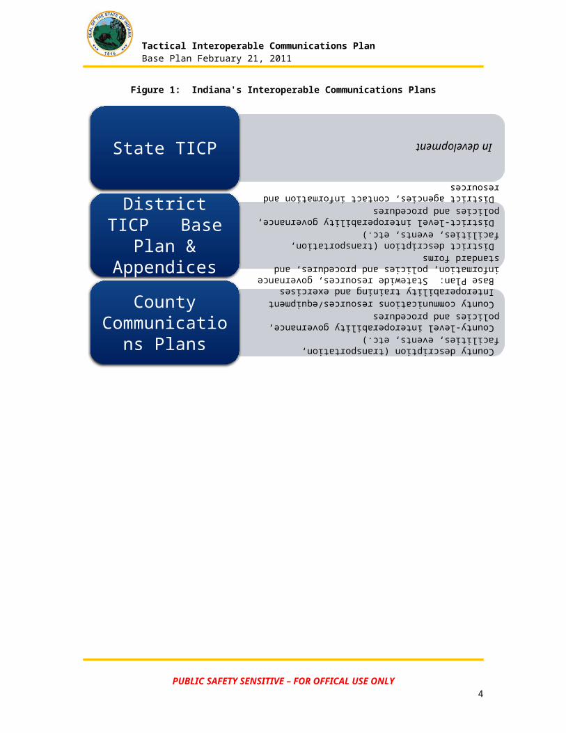
The plan is comprised of a Base Plan, which contains various materials that should be common to all Communications Plans within the State, as well as ten District-specific appendices that contain information specific to each geographic region of the state. Each District TICP is comprised of both the Base Plan, which describes equipment and procedures common to the entire state, plus the Appendix, which includes district-specific equipment and procedures. In addition, each Indiana county has a County Communications Plan. The contents of these plans are summarized below.
Figure 1: Indiana's Interoperable Communications Plans
PUBLIC SAFETY SENSITIVE – FOR OFFICAL USE ONLY3
In developmentState TICP Base Plan: Statewide resources, governance information, policies and procedures, and standard forms District description (transportation, facilities, events, etc.) District-level interoperability governance, policies and procedures District agencies, contact information and resources
District TICP Base Plan & Appendices
County description (transportation, facilities, events, etc.) County-level interoperability governance, policies and procedures County communications resources/equipment Interoperability training and exercisesCounty
Communications Plans
Tactical Interoperable Communications PlanBase Plan February 21, 2011
How to Use this PlanThe Base Plan sets forth the administrative components and technical aspects of both routine and emergency interoperability. Much of routine interoperability is achieved through system design, architecture, and engineering – strategic activities. This plan is developed in conjunction with the Communication Assets Survey and Mapping (CASM) communication database, a comprehensive collection of information about communications systems and assets. These administrative and technical matters are generally the same throughout the ten regions within the state and are therefore contained in the Base Plan.
Tactical Interoperable Communications Plans (TICPs) are designed to be used to achieve emergency interoperability and backup in the event of a catastrophic failure of all or part of the communications system. Plan authors recognize that a complete failure of an entire communications system is unlikely, but it is not impossible. These materials are designed to facilitate emergency operations during the period between discovery of the catastrophe and recovery from it.
General Communications GuidelinesThese are suggested communication guidelines to follow when using this TICP.
1. Use plain English – no codes or jargon. (This is required by Federal Law)
2. Be certain the message is received and understood.
3. Use Incident Command.
4. Stay Ahead of the Incident.
5. Remember that radio communications are one of several communications tools.
PUBLIC SAFETY SENSITIVE – FOR OFFICAL USE ONLY4

Tactical Interoperable Communications PlanBase Plan February 21, 2011
Table of ContentsPreface........................................................................................................................................... 2Plan Goals...................................................................................................................................... 2Executive Overview........................................................................................................................ 2How to Use this Plan...................................................................................................................... 4General Communications Guidelines.............................................................................................4
1 Communication with IDHS Districts....................................................................................71.1 Overview..................................................................................................................... 71.2 Governance................................................................................................................. 91.3 Agency Responsibilities and Rights..........................................................................101.4 Coordination and Assignment of Communications Assets........................................11
2 Interoperability Equipment................................................................................................122.1 Cache Radios (Swap radios).....................................................................................122.2 Shared Channels......................................................................................................122.3 Gateways..................................................................................................................122.4 Shared Systems........................................................................................................122.5 Mobile Communications Units...................................................................................12
3 Interoperability Policies and Procedures...........................................................................133.1 Plain Language.........................................................................................................133.2 Cache Radio Policies and Procedures......................................................................133.3 Shared Channel Policies and Procedures.................................................................143.4 Gateway and Console Patch Policies and Procedures.............................................213.5 Shared System Policies and Procedures..................................................................233.6 Mobile Communications Policies and Procedures....................................................23
4 Evaluation and Response Checklist..................................................................................265 CASM Overview................................................................................................................276 WebEOC (Internet-based tool)..........................................................................................277 netPlanner.........................................................................................................................278 Amateur Radio.................................................................................................................. 289 Private Sector Resources.................................................................................................2810 ICS Form 205....................................................................................................................29
Appendix A Glossary/DefinitionsAppendix B District 1 TICPAppendix C District 2 TICPAppendix D District 3 TICPAppendix E District 4 TICPAppendix F District 5 TICPAppendix G District 6 TICPAppendix H District 7 TICPAppendix I District 8 TICPAppendix J District 9 TICPAppendix K District 10 TICP
PUBLIC SAFETY SENSITIVE – FOR OFFICAL USE ONLY5
Tactical Interoperable Communications PlanBase Plan February 21, 2011
List of Figures
Figure 1: Indiana's Interoperable Communications Plans..............................................................3Figure 2: IDHS District Map...........................................................................................................7Figure 3: Indiana Interoperable Communications Governance......................................................9Figure 4: 800MHz National Conventional Interoperability NPSPAC Channels-Pre-Rebanding (217a)........................................................................................................................................... 14Figure 5: 800MHz National Conventional Interoperability NPSPAC Channels-Post-Rebanding (217a)........................................................................................................................................... 15Figure 6: VHF National Conventional Interoperability Frequencies (217a)..................................15Figure 7: UHF National Conventional Interoperability Frequencies (217a)..................................16Figure 8: Statewide and Regional Mutual Aid Talk Groups..........................................................17Figure 9: Statewide Interoperability Map......................................................................................18Figure 10: Tactical Interoperable SAFE-T Talk Group Recommendations..................................20Figure 11: Statewide Interoperability Talk Groups.......................................................................20Figure 12: National Interoperability Channels..............................................................................21Figure 13: Statewide Mobile Communications Resources...........................................................24Figure 14: Evaluation and Response Checklist...........................................................................26
PUBLIC SAFETY SENSITIVE – FOR OFFICAL USE ONLY6
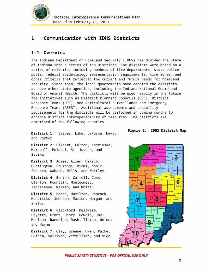
Figure 2: IDHS District Map
Tactical Interoperable Communications PlanBase Plan February 21, 2011
1 Communication with IDHS Districts
1.1 OverviewThe Indiana Department of Homeland Security (IDHS) has divided the State of Indiana into a series of ten Districts. The districts were based on a series of criteria, including numbers of fire departments, state police posts, federal epidemiology representation requirements, time zones, and other criteria that reflected the current and future needs for homeland security. Since then, the local governments have adopted the districts, as have other state agencies, including the Indiana National Guard and Board of Animal Health. The districts will be used heavily in the future for initiatives such as District Planning Councils (DPC), District Response Teams (DRT), and Agricultural Surveillance and Emergency Response Teams (ASERT). Additional assessments and capability requirements for the districts will be performed in coming months to enhance district interoperability of resources. The districts are comprised of the following counties:
District 1: Jasper, Lake, LaPorte, Newton and Porter
District 2: Elkhart, Fulton, Kosciusko, Marshall, Pulaski, St. Joseph, and Starke.
District 3: Adams, Allen, DeKalb, Huntington, LaGrange, Miami, Noble, Steuben, Wabash, Wells, and Whitley.
District 4: Benton, Carroll, Cass, Clinton, Fountain, Montgomery, Tippecanoe, Warren, and White.
District 5: Boone, Hamilton, Hancock, Hendricks, Johnson, Marion, Morgan, and Shelby.
District 6: Blackford, Delaware, Fayette, Grant, Henry, Howard, Jay, Madison, Randolph, Rush, Tipton, Union, and Wayne.
District 7: Clay, Greene, Owen, Parke, Putnam, Sullivan, Vermillion, and Vigo.
District 8: Bartholomew, Brown, Jackson, Lawrence, Monroe, Orange, and Washington.
District 9: Clark, Dearborn, Decatur, Floyd, Franklin, Harrison, Jefferson, Jennings, Ohio, Ripley, Scott, and Switzerland.
District 10: Crawford, Daviess, Dubois, Gibson, Knox, Martin, Perry, Pike, Posey, Spencer, Vanderburgh, and Warrick.
The use of District-level planning and response allows Indiana to effectively develop resources, capabilities, and capacities that facilitate discovery, response, and recovery approaches that leverage relationships, information, systems, and knowledge tools.
PUBLIC SAFETY SENSITIVE – FOR OFFICAL USE ONLY7
Tactical Interoperable Communications PlanBase Plan February 21, 2011
This plan is designed to align with The National Response Framework1. The National Response Framework (NRF) presents the guiding principles that enable all response partners to prepare for and provide a unified national response to disasters and emergencies. It establishes a comprehensive, national, all-hazards approach to domestic incident response. The National Response Plan was replaced by the National Response Framework effective March 22, 2008.
The National Response Framework defines the principles, roles, and structures that organize how we respond as a nation. The National Response Framework:
Describes how communities, tribes, states, the federal government, private-sectors, and nongovernmental partners work together to coordinate national response;
Describes specific authorities and best practices for managing incidents; and
Builds upon the National Incident Management System (NIMS)2, which provides a consistent template for managing incidents.
Information on the National Response Framework including Documents, Annexes, References and Briefings/Trainings can be accessed from the NRF Resource Center.
1 http://www.fema.gov/emergency/nrf/2 http://www.fema.gov/emergency/nims/
PUBLIC SAFETY SENSITIVE – FOR OFFICAL USE ONLY8
Tactical Interoperable Communications PlanBase Plan February 21, 2011
1.2 GovernanceThe TICP addresses interoperable communications equipment and planning statewide. Though each agency, discipline, and jurisdiction participating in this plan is unique regarding their own interoperable communication needs and capabilities, proximity to one another, population, and shared incident/event responsibilities allow them to develop a single, consolidated TICP rather than several individual, potentially incompatible, plans.
The TICP therefore consolidates information across agencies, disciplines, and jurisdictions, by documenting communications capabilities in order to provide a usable and accurate tactical incident response tool.
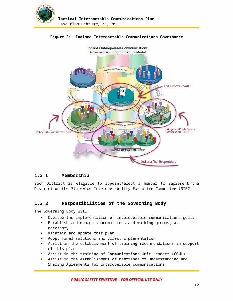
This plan has been developed under the authority of the Statewide Interoperability Coordinator (SWIC), the Integrated Public Safety Commission (IPSC), and the Statewide Interoperability Executive Committee (SIEC).
The SIEC is responsible for the creation, maintenance and implementation of this plan. The SIEC works within Indiana’s Interoperable Communications Governance Support Model, illustrated below.
Figure 3: Indiana Interoperable Communications Governance
PUBLIC SAFETY SENSITIVE – FOR OFFICAL USE ONLY9
Tactical Interoperable Communications PlanBase Plan February 21, 2011
1.2.1 MembershipEach District is eligible to appoint/elect a member to represent the District on the Statewide Interoperability Executive Committee (SIEC).
1.2.2 Responsibilities of the Governing BodyThe Governing Body will:
Oversee the implementation of interoperable communications goals Establish and manage subcommittees and working groups, as necessary Maintain and update this plan Adopt final solutions and direct implementation Assist in the establishment of training recommendations in support of this plan Assist in the training of Communications Unit Leaders (COML) Assist in the establishment of Memoranda of Understanding and Sharing Agreements for
interoperable communications Coordination of exercises with respect to the District Plan Re-evaluate this plan as technology evolves and circumstances dictate
1.2.3 Meeting ScheduleThe SIEC meeting schedule will be established by the SIEC Chairman.
1.2.4 TICP Maintenance and UpdateThe Governing Body has the responsibility to review this document annually. Requests for modifications or additions to this document should be submitted to the TICP Point of Contact. Updates to this document can be recommended by any of the Districts or participating agencies.
1.3 Agency Responsibilities and RightsAgencies will retain the following rights and responsibilities:
Agencies are responsible for considering and, if agreeing to, complying with MOUs and Agreements developed within their region in coordination with their respective jurisdictions.
Authorized representatives of agencies participating in this plan have the authority to request the use of equipment, including systems and mobile assets, in accordance with Standard Operating Procedures (SOPs).
Where applicable, agencies will be responsible for consistently maintaining, testing, and exercising connectivity to interoperable communications.
Agencies retain the right to decide when and where to participate in interoperable communications. For example, agencies will retain the right to accept or decline a patch to a gateway system to provide interoperable communications during an incident.
PUBLIC SAFETY SENSITIVE – FOR OFFICAL USE ONLY10
Tactical Interoperable Communications PlanBase Plan February 21, 2011
1.4 Coordination and Assignment of Communications AssetsIn response to incidents which cross over political jurisdictions, there will potentially be competing demands and priorities for interoperable communications assets.
When the same resources are requested for two or more incidents, resource assignments should be based on the priority levels below:
1. Disaster, large scale incident, or extreme emergency where imminent danger exists to life or property, and requires mutual aid or interagency communications
2. Other incidents requiring the response of multiple agencies
3. Pre-planned events requiring mutual aid or interagency communications
4. Incidents involving a single agency where supplemental communications are needed for agency use
5. Drills, tests and exercises
In the event of multiple simultaneous incidents within the same priority, the resources should be allocated according to the following:
1. Incidents with the greatest level of exigency (e.g., greater threat to life or property or more immediate need) have priority over less exigent incidents.
2. Agencies with single/limited interoperable options have priority use of those options over agencies with multiple interoperable options.
3. When possible, agencies already using an interoperable asset during an event should not be redirected to another resource.
PUBLIC SAFETY SENSITIVE – FOR OFFICAL USE ONLY11
Tactical Interoperable Communications PlanBase Plan February 21, 2011
2 Interoperability EquipmentSAFECOM defines communications interoperability as the ability of public safety agencies to talk across disciplines and jurisdictions via radio communication systems, exchanging voice and/or data with one another on demand, in real time, when needed, and as authorized. Specific Interoperability resources may be identified from the CASM database.
2.1 Cache Radios (Swap radios)“Swapping radios” refers to maintaining a cache of standby radios which can be deployed to support incidents within the district. These radios may be from a State cache, a regional cache, or from a participating agency. These caches allow all responders to use a common, compatible set of radios during an incident. Specific caches may be identified within the CASM database.
2.2 Shared Channels“Shared channels” refer to common frequencies, channels, or talk groups (such as those of a participating agency) which have been established and are programmed into radios to provide interoperable communications among agencies. Specific shared interoperable communications channels may be identified within the CASM database.
2.3 Gateways“Gateway” systems interconnect channels or talk groups (whether on different systems, bands or modes), allowing first responders to use their existing radios and channels to be interconnected with the channels or talk groups of other users outside of their agency. Gateways may be identified within the CASM database. Consoles capable of “patching” are considered to be “gateways” for the purpose of this plan.
2.4 Shared Systems“Shared systems” refers to the use of a single radio system infrastructure to provide service to several Public Safety agencies within an area. The Statewide IPSC system is an example of a shared system. Specific systems may be identified in the CASM database.
2.5 Mobile Communications UnitsThese Mobile Communication Units assist in the support of communications for all agencies and are capable of movement from place to place as necessary. Local and regional resources are listed in District appendices. Statewide resources and policies are described in Section 3.6.
PUBLIC SAFETY SENSITIVE – FOR OFFICAL USE ONLY12
Tactical Interoperable Communications PlanBase Plan February 21, 2011
3 Interoperability Policies and ProceduresThis section describes all interoperable communications equipment and all associated policies and procedures.
3.1 Plain LanguageThe use of common terminology is about the ability of commanders, State and local EOC personnel, federal operational coordinators, and emergency responders to communicate clearly with each other and effectively coordinate response activities, no matter what the size, scope or complexity of the incident. The ability of responders from different jurisdictions and different disciplines to work together depends greatly on their ability to communicate and understand each other. Unit Identification - Agency name shall precede unit identifier, i.e., LaPorte 36, Carmel Engine 45.
It is required that plain language be used for multi-agency, multi-jurisdiction and multi-discipline interoperable events, such as major disasters and exercises.
3.2 Cache Radio Policies and ProceduresListed Cache radios are available for any agencies to use during times of emergency.
3.2.1 Cache Provider ResponsibilitiesFor a radio cache to be an effective shared resource, it should have the following characteristics:
Be fully charged and maintained, ready for deployment at all times Include extra charged/replacement batteries and chargers for extended deployments Personnel available to transport the radios to the incident scene Available support personnel for on-scene support during the deployment Radios should be labeled with owning agency information and operating instructions Each radio cache shall have a designated radio cache manager Check-out and tracking procedures are used during the incident to ensure the radios are
properly returned to the cache following the incident
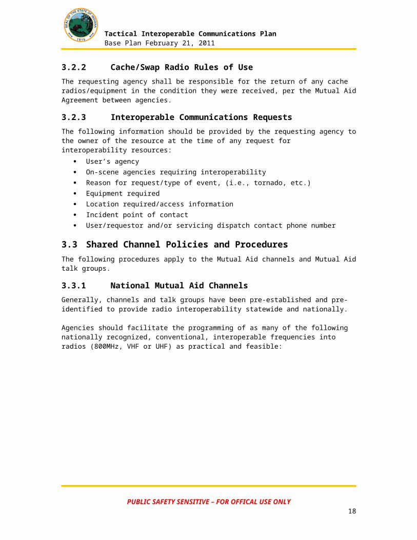
3.2.2 Cache/Swap Radio Rules of UseThe requesting agency shall be responsible for the return of any cache radios/equipment in the condition they were received, per the Mutual Aid Agreement between agencies.
3.2.3 Interoperable Communications RequestsThe following information should be provided by the requesting agency to the owner of the resource at the time of any request for interoperability resources:
User’s agency On-scene agencies requiring interoperability Reason for request/type of event, (i.e., tornado, etc.) Equipment required Location required/access information Incident point of contact User/requestor and/or servicing dispatch contact phone number
PUBLIC SAFETY SENSITIVE – FOR OFFICAL USE ONLY13
Tactical Interoperable Communications PlanBase Plan February 21, 2011
3.3 Shared Channel Policies and ProceduresThe following procedures apply to the Mutual Aid channels and Mutual Aid talk groups.
3.3.1 National Mutual Aid ChannelsGenerally, channels and talk groups have been pre-established and pre-identified to provide radio interoperability statewide and nationally.
Agencies should facilitate the programming of as many of the following nationally recognized, conventional, interoperable frequencies into radios (800MHz, VHF or UHF) as practical and feasible:
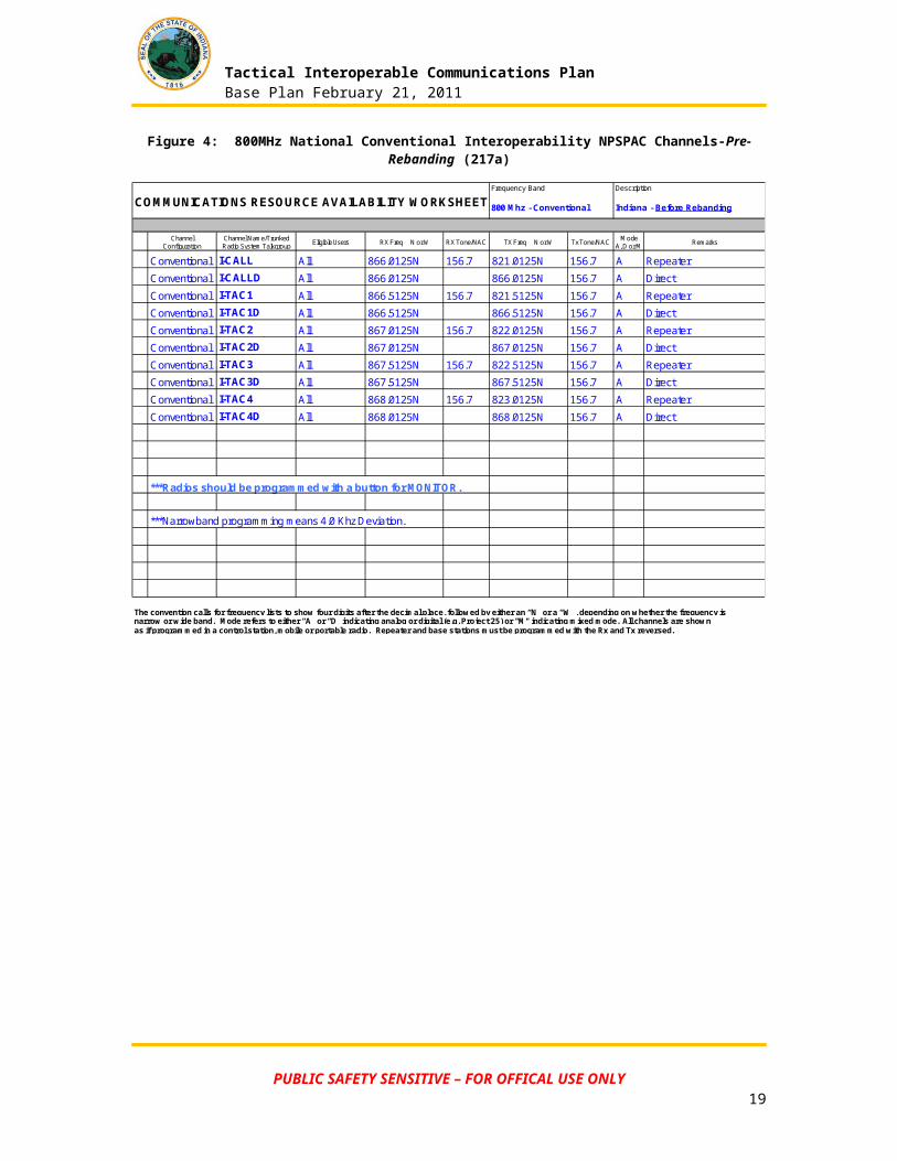
Figure 4: 800MHz National Conventional Interoperability NPSPAC Channels-Pre-Rebanding (217a)
Channel Configuration
Channel Name/Trunked Radio System Talkgroup Eligible Users RX Freq N or W RX Tone/NAC TX Freq N or W Tx Tone/NAC Mode
A, D or M Remarks
Conventional I-CALL All 866.0125N 156.7 821.0125N 156.7 A Repeater
Conventional I-CALLD All 866.0125N 866.0125N 156.7 A Direct
Conventional I-TAC1 All 866.5125N 156.7 821.5125N 156.7 A Repeater
Conventional I-TAC1D All 866.5125N 866.5125N 156.7 A Direct
Conventional I-TAC2 All 867.0125N 156.7 822.0125N 156.7 A Repeater
Conventional I-TAC2D All 867.0125N 867.0125N 156.7 A Direct
Conventional I-TAC3 All 867.5125N 156.7 822.5125N 156.7 A Repeater
Conventional I-TAC3D All 867.5125N 867.5125N 156.7 A Direct
Conventional I-TAC4 All 868.0125N 156.7 823.0125N 156.7 A Repeater
Conventional I-TAC4D All 868.0125N 868.0125N 156.7 A Direct
***Radios should be programmed with a button for MONITOR.
***Narrowband programming means 4.0 Khz Deviation.
The convention calls for frequency lists to show four digits after the decimal place, followed by either an “N” or a “W”, depending on whether the frequency isnarrow or wide band. Mode refers to either “A” or “D” indicating analog or digital (e.g. Project 25) or "M" indicating mixed mode. All channels are shownas if programmed in a control station, mobile or portable radio. Repeater and base stations must be programmed with the Rx and Tx reversed.
COMMUNICATIONS RESOURCE AVAILABILITY WORKSHEET 800 Mhz - Conventional
Frequency Band Description
Indiana - Before Rebanding
PUBLIC SAFETY SENSITIVE – FOR OFFICAL USE ONLY14
Tactical Interoperable Communications PlanBase Plan February 21, 2011
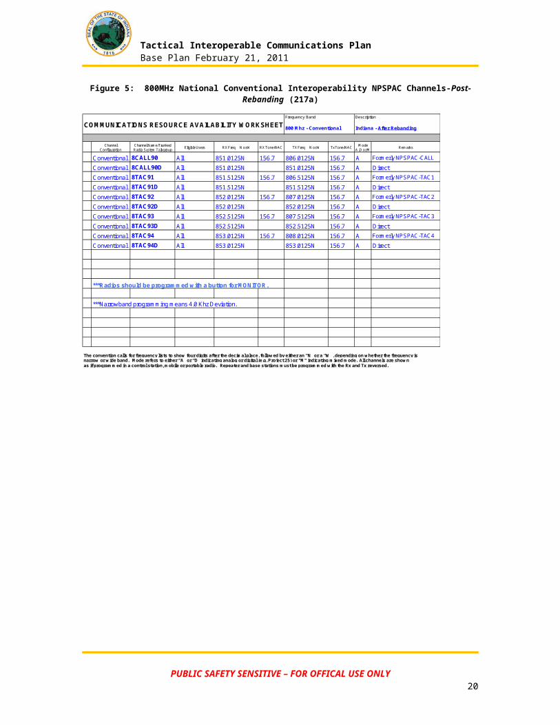
Figure 5: 800MHz National Conventional Interoperability NPSPAC Channels-Post-Rebanding (217a)
Channel Configuration
Channel Name/Trunked Radio System Talkgroup Eligible Users RX Freq N or W RX Tone/NAC TX Freq N or W Tx Tone/NAC Mode
A, D or M Remarks
Conventional 8CALL90 All 851.0125N 156.7 806.0125N 156.7 A Formerly NPSPAC-CALL
Conventional 8CALL90D All 851.0125N 851.0125N 156.7 A Direct
Conventional 8TAC91 All 851.5125N 156.7 806.5125N 156.7 A Formerly NPSPAC-TAC1
Conventional 8TAC91D All 851.5125N 851.5125N 156.7 A Direct
Conventional 8TAC92 All 852.0125N 156.7 807.0125N 156.7 A Formerly NPSPAC-TAC2
Conventional 8TAC92D All 852.0125N 852.0125N 156.7 A Direct
Conventional 8TAC93 All 852.5125N 156.7 807.5125N 156.7 A Formerly NPSPAC-TAC3
Conventional 8TAC93D All 852.5125N 852.5125N 156.7 A Direct
Conventional 8TAC94 All 853.0125N 156.7 808.0125N 156.7 A Formerly NPSPAC-TAC4
Conventional 8TAC94D All 853.0125N 853.0125N 156.7 A Direct
***Radios should be programmed with a button for MONITOR.
***Narrowband programming means 4.0 Khz Deviation.
The convention calls for frequency lists to show four digits after the decimal place, followed by either an “N” or a “W”, depending on whether the frequency isnarrow or wide band. Mode refers to either “A” or “D” indicating analog or digital (e.g. Project 25) or "M" indicating mixed mode. All channels are shownas if programmed in a control station, mobile or portable radio. Repeater and base stations must be programmed with the Rx and Tx reversed.
COMMUNICATIONS RESOURCE AVAILABILITY WORKSHEET 800 Mhz - Conventional
Frequency Band Description
Indiana - After Rebanding
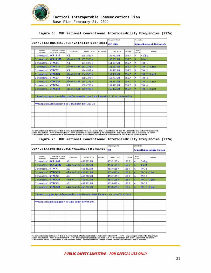
Figure 6: VHF National Conventional Interoperability Frequencies (217a)
Channel Configuration
Channel Name/Trunked Radio System Talkgroup Eligible Users RX Freq N or W RX Tone/NAC TX Freq N or W Tx Tone/NAC Mode
A, D or M Remarks
Conventional VCALL10 All 155.7525 N 155.7525 N 156.7 A Calling
Conventional VCALL10D All on KA 2181 155.7525 N 155.7525 N 156.7 A DirectConventional VTAC11 All 151.1375 N 151.1375 N 156.7 A TAC 1
Conventional VTAC11D All on KA 2181 151.1375 N 151.1375 N 156.7 A TAC 1 - Direct
Conventional VTAC12 All 154.4525 N 154.4525 N 156.7 A TAC 2Conventional VTAC12D All on KA 2181 154.4525 N 154.4525 N 156.7 A TAC 2 - Direct
Conventional VTAC13 All 158.7375 N 158.7375 N 156.7 A TAC 3
Conventional VTAC13D All on KA 2181 158.7375 N 158.7375 N 156.7 A TAC 3 - Direct
Conventional VTAC14 All 159.4725 N 159.4725 N 156.7 A TAC 4Conventional VTAC14D All on KA 2181 159.4725 N 159.4725 N 156.7 A TAC 4 - Direct
Cleared to program in mobiles/portables statewide under State license KA 2181 as of 03/01/2010
***Radios should be programmed with a button for MONITOR
The convention calls for frequency lists to show four digits after the decimal place, followed by either an “N” or a “W”, depending on whether the frequency isnarrow or wide band. Mode refers to either “A” or “D” indicating analog or digital (e.g. Project 25) or "M" indicating mixed mode. All channels are shownas if programmed in a control station, mobile or portable radio. Repeater and base stations must be programmed with the Rx and Tx reversed.
COMMUNICATIONS RESOURCE AVAILABILITY WORKSHEET VHF - High
Frequency Band Description
National Interoperability Channels
PUBLIC SAFETY SENSITIVE – FOR OFFICAL USE ONLY15
Tactical Interoperable Communications PlanBase Plan February 21, 2011
Figure 7: UHF National Conventional Interoperability Frequencies (217a)
Channel Configuration
Channel Name/Trunked Radio System Talkgroup Eligible Users RX Freq N or W RX Tone/NAC TX Freq N or W Tx Tone/NAC Mode
A, D or M Remarks
Conventional UCALL40 All 458.2125 N 453.2125 N 156.7 A Calling
Conventional UCALL40D All on KA 2181 453.2125 N 453.2125 N 156.7 A Direct
Conventional UTAC41 All 458.4625 N 453.4625 N 156.7 A TAC 1
Conventional UTAC41D All on KA 2181 453.4625 N 453.4625 N 156.7 A TAC 1 - Direct
Conventional UTAC42 All 458.7125 N 453.7125 N 156.7 A TAC 2
Conventional UTAC42D All on KA 2181 453.7125 N 453.7125 N 156.7 A TAC 2 - Direct
Conventional UTAC43 All 458.8625 N 453.8625 N 156.7 A TAC 3
Conventional UTAC43D All on KA 2181 453.8625 N 453.8625 N 156.7 A TAC 3 - Direct
Cleared to program in mobiles/portables statewide under State license KA 2181 as of 03/01/2010
***Radios should be programmed with a button for MONITOR
The convention calls for frequency lists to show four digits after the decimal place, followed by either an “N” or a “W”, depending on whether the frequency isnarrow or wide band. Mode refers to either “A” or “D” indicating analog or digital (e.g. Project 25) or "M" indicating mixed mode. All channels are shownas if programmed in a control station, mobile or portable radio. Repeater and base stations must be programmed with the Rx and Tx reversed.
COMMUNICATIONS RESOURCE AVAILABILITY WORKSHEET UHF
Frequency Band Description
National Interoperability Channels
PUBLIC SAFETY SENSITIVE – FOR OFFICAL USE ONLY16
Tactical Interoperable Communications PlanBase Plan February 21, 2011
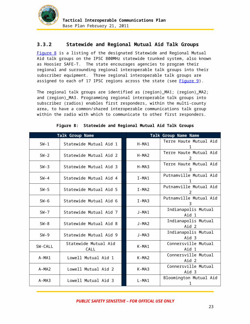
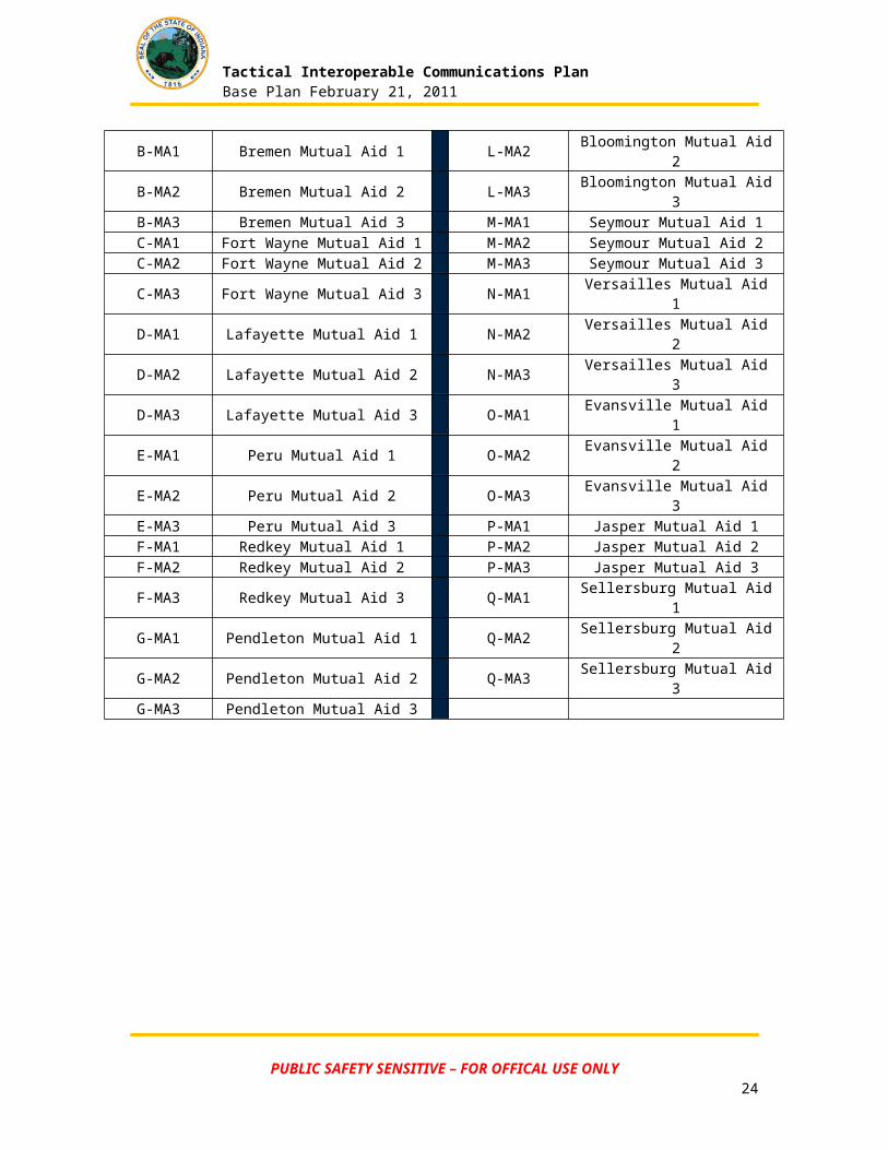
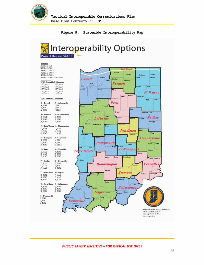
3.3.2 Statewide and Regional Mutual Aid Talk GroupsFigure 8 is a listing of the designated Statewide and Regional Mutual Aid talk groups on the IPSC 800MHz statewide trunked system, also known as Hoosier SAFE-T. The state encourages agencies to program their regional and surrounding regional interoperable talk groups into their subscriber equipment. Three regional interoperable talk groups are assigned to each of 17 IPSC regions across the state (see Figure 9).
The regional talk groups are identified as (region)_MA1; (region)_MA2; and (region)_MA3. Programming regional interoperable talk groups into subscriber (radios) enables first responders, within the multi-county area, to have a common/shared interoperable communications talk group within the radio with which to communicate to other first responders.
Figure 8: Statewide and Regional Mutual Aid Talk Groups
Talk Group Name Talk Group Name NameSW-1 Statewide Mutual Aid 1 H-MA1 Terre Haute Mutual Aid 1SW-2 Statewide Mutual Aid 2 H-MA2 Terre Haute Mutual Aid 2SW-3 Statewide Mutual Aid 3 H-MA3 Terre Haute Mutual Aid 3SW-4 Statewide Mutual Aid 4 I-MA1 Putnamville Mutual Aid 1SW-5 Statewide Mutual Aid 5 I-MA2 Putnamville Mutual Aid 2SW-6 Statewide Mutual Aid 6 I-MA3 Putnamville Mutual Aid 3SW-7 Statewide Mutual Aid 7 J-MA1 Indianapolis Mutual Aid 1SW-8 Statewide Mutual Aid 8 J-MA2 Indianapolis Mutual Aid 2SW-9 Statewide Mutual Aid 9 J-MA3 Indianapolis Mutual Aid 3
SW-CALL Statewide Mutual Aid CALL K-MA1 Connersville Mutual Aid 1A-MA1 Lowell Mutual Aid 1 K-MA2 Connersville Mutual Aid 2A-MA2 Lowell Mutual Aid 2 K-MA3 Connersville Mutual Aid 3A-MA3 Lowell Mutual Aid 3 L-MA1 Bloomington Mutual Aid 1B-MA1 Bremen Mutual Aid 1 L-MA2 Bloomington Mutual Aid 2B-MA2 Bremen Mutual Aid 2 L-MA3 Bloomington Mutual Aid 3B-MA3 Bremen Mutual Aid 3 M-MA1 Seymour Mutual Aid 1C-MA1 Fort Wayne Mutual Aid 1 M-MA2 Seymour Mutual Aid 2C-MA2 Fort Wayne Mutual Aid 2 M-MA3 Seymour Mutual Aid 3C-MA3 Fort Wayne Mutual Aid 3 N-MA1 Versailles Mutual Aid 1D-MA1 Lafayette Mutual Aid 1 N-MA2 Versailles Mutual Aid 2D-MA2 Lafayette Mutual Aid 2 N-MA3 Versailles Mutual Aid 3D-MA3 Lafayette Mutual Aid 3 O-MA1 Evansville Mutual Aid 1E-MA1 Peru Mutual Aid 1 O-MA2 Evansville Mutual Aid 2E-MA2 Peru Mutual Aid 2 O-MA3 Evansville Mutual Aid 3E-MA3 Peru Mutual Aid 3 P-MA1 Jasper Mutual Aid 1F-MA1 Redkey Mutual Aid 1 P-MA2 Jasper Mutual Aid 2F-MA2 Redkey Mutual Aid 2 P-MA3 Jasper Mutual Aid 3F-MA3 Redkey Mutual Aid 3 Q-MA1 Sellersburg Mutual Aid 1G-MA1 Pendleton Mutual Aid 1 Q-MA2 Sellersburg Mutual Aid 2G-MA2 Pendleton Mutual Aid 2 Q-MA3 Sellersburg Mutual Aid 3G-MA3 Pendleton Mutual Aid 3
PUBLIC SAFETY SENSITIVE – FOR OFFICAL USE ONLY17
Tactical Interoperable Communications PlanBase Plan February 21, 2011
Figure 9: Statewide Interoperability Map
PUBLIC SAFETY SENSITIVE – FOR OFFICAL USE ONLY18
Tactical Interoperable Communications PlanBase Plan February 21, 2011
3.3.3 Mutual Aid Talk Group Rules of UseThe Regional Mutual Aid talk groups on the IPSC system are available for use on a first-come, first served basis for inter-communication in situations requiring the coordination of multiple public safety entities. MA-1 is specifically designed for hot broadcasts and should not be routinely used for exercises or general coordination efforts. MA-2 or MA-3 may be used for exercises, coordination efforts or on scene communications.
3.3.4 General Talk Group Usage GuidelinesReliance upon any talk groups on the IPSC system should take into account the following:
1. Overloading (busying-out) the available resources on the IPSC system. 2. Any incident has the potential of taking out T-1 lines which the IPSC system is reliant
upon. One or more sites may be in SITE TRUNKING during the event.
3.3.5 Shared Channel/Talk Group Usage RecommendationsRegional Mutual Aid talk groups are available for use by any participant in Project Hoosier SAFE-T; they do not belong to any one agency. The opportunity to use regional mutual aid talk groups vary with the type of incident, number of responding agencies and varied services.
Agencies are encouraged to use the regional interoperable talk group (MA1) for broadcast of incidents that are considered “hot” calls, or other calls that may require assistance from multiple agencies operating within the same geographical area. Examples of “hot” calls that qualify for regional broadcast include: pursuits, personal injury crash, officer requesting aid or assistance, bank alarms, robbery in progress and any other emergency radio traffic deemed appropriate by the dispatcher or first responder in the field.
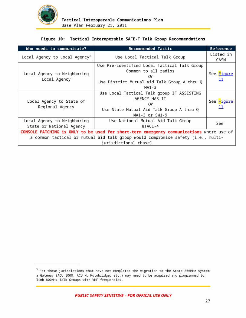
See Figure 10 for recommendations for agency use of local tactical, District, State or National Mutual Aid talk groups.
PUBLIC SAFETY SENSITIVE – FOR OFFICAL USE ONLY19
Local Agency to State or Regional AgencyAlso used for scheduled special events
Local Agency to Neighboring Local Agency
Tactical Interoperable Communications PlanBase Plan February 21, 2011
Figure 10: Tactical Interoperable SAFE-T Talk Group Recommendations
Who needs to communicate? Recommended Tactic Reference
Local Agency to Local Agency3 Use Local Tactical Talk Group Listed in CASM
Local Agency to Neighboring Local AgencyUse Pre-identified Local Tactical Talk Group Common to all radios
OrUse District Mutual Aid Talk Group A thru Q MA1-3
See Figure 11
Local Agency to State of Regional AgencyUse Local Tactical Talk group IF ASSISTING AGENCY HAS IT
OrUse State Mutual Aid Talk Group A thru Q MA1-3 or SW1-9
See Figure 11
Local Agency to Neighboring State or National Agency
Use National Mutual Aid Talk Group 8TAC1-4 See
CONSOLE PATCHING is ONLY to be used for short-term emergency communications where use of a common tactical or mutual aid talk group would compromise safety (i.e., multi-jurisdictional chase)
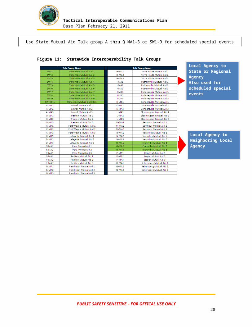
Use State Mutual Aid Talk group A thru Q MA1-3 or SW1-9 for scheduled special events
Figure 11: Statewide Interoperability Talk Groups
3 For those jurisdictions that have not completed the migration to the State 800MHz system a Gateway (ACU 1000, ACU M, Motobridge, etc.) may need to be acquired and programmed to link 800MHz Talk Groups with VHF frequencies.
PUBLIC SAFETY SENSITIVE – FOR OFFICAL USE ONLY20
Local Agency to
Neighboring State or National Agency
Tactical Interoperable Communications PlanBase Plan February 21, 2011
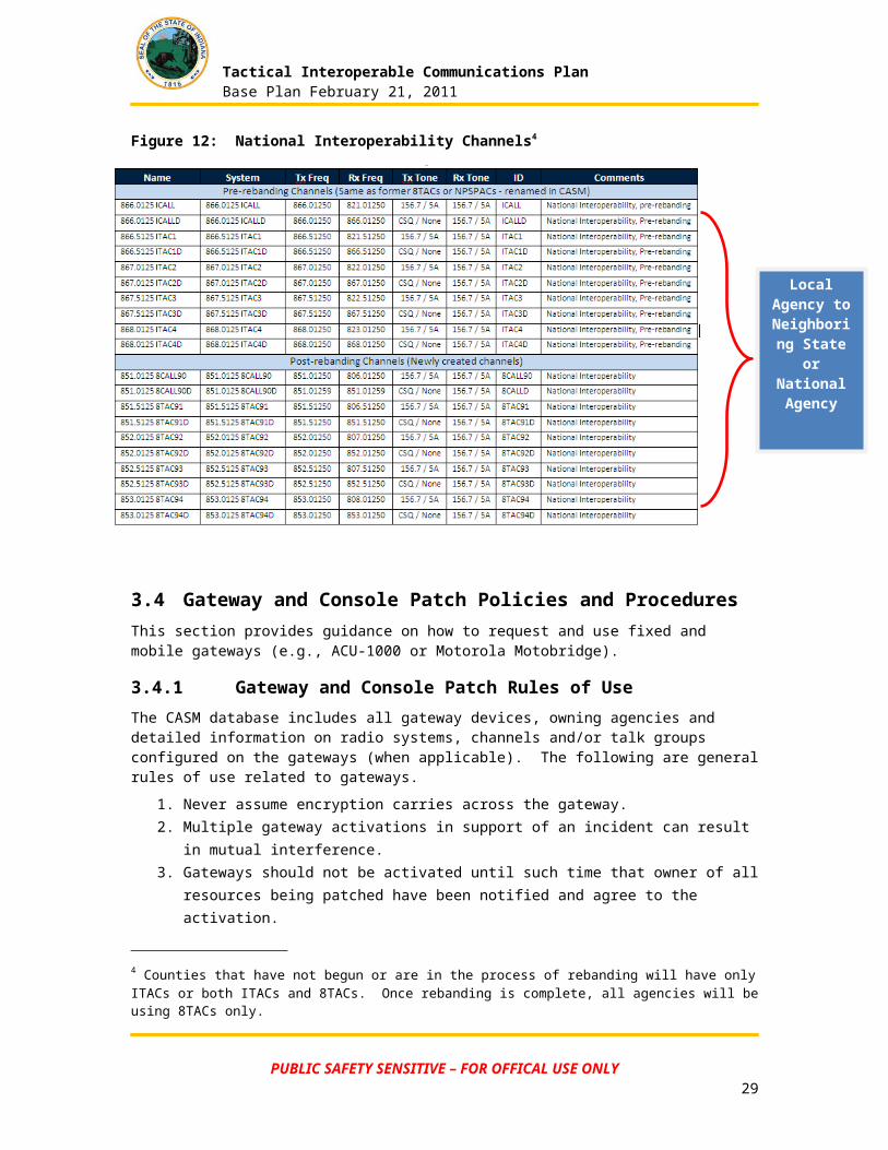
Figure 12: National Interoperability Channels4
3.4 Gateway and Console Patch Policies and ProceduresThis section provides guidance on how to request and use fixed and mobile gateways (e.g., ACU-1000 or Motorola Motobridge).
3.4.1 Gateway and Console Patch Rules of UseThe CASM database includes all gateway devices, owning agencies and detailed information on radio systems, channels and/or talk groups configured on the gateways (when applicable). The following are general rules of use related to gateways.
1. Never assume encryption carries across the gateway.2. Multiple gateway activations in support of an incident can result in mutual interference.3. Gateways should not be activated until such time that owner of all resources being
patched have been notified and agree to the activation.4. Home system coverage may limit communications: Users must be within the footprint of
the coverage area.
Agencies patching to the IPSC, 800 MHz, statewide, trunked system should adhere to the following guidelines:
Due to the configuration of the IPSC radio system the following rules must be followed when patching IPSC to other radio systems. This policy involves patching to or within the IPSC statewide 800 Mhz trunked radio system.
4 Counties that have not begun or are in the process of rebanding will have only ITACs or both ITACs and 8TACs. Once rebanding is complete, all agencies will be using 8TACs only.
PUBLIC SAFETY SENSITIVE – FOR OFFICAL USE ONLY21

Tactical Interoperable Communications PlanBase Plan February 21, 2011
o Short-Term Patch refers to a patch that is intended to be used for 30 minutes or less. You do not need to notify IPSC in this case.
o Long Term Patch refers to a patch that is in place longer than 30 minutes. You must notify IPSC at 317-234-1540, and provide the following information:
Location of Patch Name, Address, Telephone number and Email (if any) of the specific
person responsible for the patch Talk Group(s) patched Anticipated length of patch Purpose of patch IPSC reserves the right to break any/all patches at any time
NOTE: IPSC must be notified at 317-234-1540 when the approved long-term patch is broken.
3.4.2 Gateway and Console Patch Communications RequestThe following information should be provided by the requesting agency at the time of an activation request:
User’s agency Talk Groups or Radio Channels which need to be patched
User/requestor and/or servicing dispatch contact phone number
3.4.3 Gateway and Console Patch ActivationOnce authorization has been granted, each entity should follow their internal procedures for activating the connectivity. Procedures for establishing communications connectivity include:
Selection of a channel or talk group on your home system if necessary Contact IPSC at 317-234-1540 if the talk groups being patched are IPSC talk groups Verify system-wide availability of required resources – coordination among control point
dispatchers Provide radio call sign/designator information to connected agencies as needed Assign the requested unit/agency to that channel or talk group Utilize your agency’s internal procedures for establishing connectivity between the
agencies The control point dispatcher will connect the agency to the appropriate talk group Announce to users when interoperability is activated
3.4.4 Gateway and Console Patch DeactivationWhen the interoperable communications connection is no longer required, entities should follow these deactivation procedures:
The requesting agency/user or incident commander where the emergency event occurred shall contact their dispatcher so the patch can be deactivated
The dispatcher shall make an announcement on the interoperable channel/talk group indicating the connection will be deactivated prior to the connection being disabled
All personnel shall return to their appropriate home system channel assignment Notify IPSC at 317-234-1540 when the Long Term Patch is broken
PUBLIC SAFETY SENSITIVE – FOR OFFICAL USE ONLY22
Tactical Interoperable Communications PlanBase Plan February 21, 2011
3.4.5 Problem ID and ResolutionFollowing an incident or during post incident debriefing, agencies using gateways will report any problems encountered to the appropriate POC for the Gateway. The POC will be responsible for ensuring effective resolution to problems which exist with the gateway.
3.4.6 Gateway Test ProceduresTo ensure equipment components of the interoperability solution are operating properly, each agency should participate in regular testing as established by agreement of the agencies.
3.5 Shared System Policies and ProceduresThe shared system in Indiana with the broadest use and application is Hoosier SAFE-T. SAFE-T, completed in the summer of 2007, is an 800 MHz trunked voice and data communications system which provides both day-to-day and mission critical interoperability for Indiana local, state and federal first responders and public safety officials. SAFE-T supports both analog and digital radios, providing 95% mobile and portable radio coverage statewide using 130+ communications sites throughout Indiana. The State of Indiana has established both regional and statewide talk groups to facilitate interoperable communications for 800 MHz users. For policies and procedures regarding SAFE-T usage, see Section 3.3.
3.5.1 Problem ID and ResolutionPublic safety agencies throughout the state also communicate using shared UHF, VHF and stand-alone 800MHz systems. Agencies should identify and resolve problems in accordance with policies already established for their shared systems.
3.6 Mobile Communications Policies and ProceduresIDHS and IPSC maintain the following statewide mobile communications resources that may be used by public safety agencies statewide, as appropriate.
For IPSC’s Mobile Intelli-Repeater Sites (MIRS) I and II, requests for deployment should be made by phone to IPSC at 317-234-1540 (24/7 phone number).
For all IDHS resources listed in Figure 13, requests for assistance must come from the county emergency management director to the State EOC. The State EOC will determine the most appropriate resource to meet the mission request.
PUBLIC SAFETY SENSITIVE – FOR OFFICAL USE ONLY23
Tactical Interoperable Communications PlanBase Plan February 21, 2011
Figure 13: Statewide Mobile Communications Resources
Resource Name Agency DescriptionMobile Intelli-Repeater Site (MIRS) I
Mobile Intelli-Repeater Site (MIRS) II
IPSC Portable, 5-channel site with an antennae. Has the ability to connect to existing T1 telecommunication circuits with instantaneous results. MIRS is also used to boost communications coverage during special events that require concentrated coverage or specialized communications. Each MIRS houses a Motorola Motobridge to provide interoperable communications among VHF, UHF, and other radio systems and is available to any public safety agency during an emergency.
BGAN Satellite Units (16) IDHS Satellite transponders to support 1 to 11 users. Contains built-in Wi-Fi and supports data communications. Units are strategically located throughout the state for immediate response.
Satellite Office Solution (SOS)
IDHS Two systems to support field/office operations. Each system includes: support trailer with generator, 1-1.5M satellite dish, Wi-Fi (State network and public), 15 laptops, 15 VOIP phones with video capabilities and a scanner/printer.
Incident Response Vehicle (IRV)
IDHS Rapid incident response vehicle, can be operational within 10 minutes. Unit has satellite connectivity, weather station, video teleconferencing and internal/external Wi-Fi (State network and public). Radio systems include VHF, UHF, HF, aircraft, marine, amateur and radio patching (ACU-2000). A 40’ mast camera capable of sending live video to State EOC. Each of the 12 workstations includes a VOIP phone with video and a computer with internet access.
Mobile Command Center (MCC)
IDHS Robust response vehicle (53’ semi-trailer) capable of supporting 30 personnel. Trailer has satellite connectivity, weather station, video teleconferencing and internal/external Wi-Fi (State network and public). Radio systems include VHF, UHF, HF, aircraft, marine, amateur and radio patching (ACU-2000). A 40’ most camera is capable of sending live video to State EOC.
Mobile Intelli-Repeater Site (MIRS)
PUBLIC SAFETY SENSITIVE – FOR OFFICAL USE ONLY24
Tactical Interoperable Communications PlanBase Plan February 21, 2011
Satellite Office Solution (SOS)
Incident Response Vehicle (IRV)
Mobile Command Center (MCC)
PUBLIC SAFETY SENSITIVE – FOR OFFICAL USE ONLY25
BGAN Satellite Units
Tactical Interoperable Communications PlanBase Plan February 21, 2011
4 Evaluation and Response ChecklistThis figure contains checklists and emergency action steps that should be used to evaluate a systemic failure or interruption. The table should be used left to right, to evaluate the problem and respond to it. It is specifically designed to address the unique facts and circumstances of the problem at hand and to assist in the crafting of an appropriate response.
Figure 14: Evaluation and Response Checklist
COMMUNICATIONS SYSTEM INCIDENT EVALUATION AND RESPONSEEVALUATION MATRIX INTEROPERABILTY RESPONSE
□ What is damaged?□ PSAP/Call Center□ 911/Telephone□ Electricity□ CAD□ Alerting/Paging/Mobile Data□ Data/Records System□ Transmission Equipment□ Tower(s)
□ What caused the damage?
□ Is the facility safe to occupy & use?
□ How long will it take to restore?
□ What resources are needed?
□ Onsite Redundancy/Backup□ County Redundancy/Backup□ Radio to Radio□ Mobile Communication Van(s)□ Alternate Facility within District□ Alternate District□ SAFE-T (IPSC)□ Amateur Radio (RACES)□ Public Cellular□ Voice□ Text Message□ Internet Access
□ Wireline Telephony□ Voice□ Outbound Messaging (Reverse 911)
□ Internet (Web) Tools□ WebEOC□ Electronic Mail□ Social Media (Facebook, etc.)
□ Hardcopy Messenger□ Fire Station(s)□ Convenience Store(s)
GENERAL RESPONSE NOTIFICATIONS
□ Identify nature and extent of problem□ Determine whether protective action is needed (including personal protective measures and evacuation)□Warn others as needed□ Call for more help than you need□ Assess situation□ Evaluate action options□ Secure assets□ Initiate best course of action
□ Field Personnel (system users)□ Call Center Manager(s)□ District PSAP’s□ County Officials/EMA□ IDHS□ Coordinate State/Federal Resource requests□ Coordinate Damage Assessment□ Disaster Declarations□ Resource requests□ Regional Support
□ Public Carriers□ Utilities□ Media□ Provide Warning□ What has happened□ When it happened□ Where it happened□ Who/what is involved□ What is being done in response□ What people should do□ What services are available□ Why it happened (if known)□ How it happened (if know)□ What investigative steps are being taken□ What is being done to repair/restore normalcy
PUBLIC SAFETY SENSITIVE – FOR OFFICAL USE ONLY26
Tactical Interoperable Communications PlanBase Plan February 21, 2011
5 CASM OverviewIndiana is using a US Department of Homeland Security/Office of Emergency Communications (DHS/OEC) sponsored tool to effectively analyze public safety communications equipment data, identify interoperability gaps in communications plans and collaborate on solutions for improvement. The Communication Assets Survey and Mapping (CASM) tool is a standardized collection method for emergency response agencies to store and visually display data about their public safety communications assets and how those assets are used. CASM provides:
A single repository for information about land mobile radio systems, methods of interoperability and how they are used by emergency responders
A means to display the data Tools to analyze the data and visualize interoperability gaps in accordance with the
SAFECOM Interoperability Continuum framework
For more about the CASM tool or to request access, visit http://www.in.gov/ipsc/2529.htm.
6 WebEOC (Internet-based tool)Software Designed by Emergency Services integrators (ESi) to bring real-time emergency information management to any size Emergency Operations Center. A breakthrough application of web-based technology from ESi puts integrated information management within the budget of any emergency operations
center. This results in secure, real-time access to state and national weather trends, satellite images, mapping information, details of operations in other jurisdictions, local, regional and even national resource status and other data vital to the efficient management of any contingency (even if the jurisdiction hasn't invested in any of the sources of these data). Communication Assets Survey and Mapping (CASM) tool provides the ability for representatives of public safety agencies within an urban area or State to collect, store, and visualize data about agencies, communication assets, and how agencies use those assets.
7 netPlanner
netPlanner is a browser enabled database application that centrally stores your Emergency Plans and allows plan stakeholders with proper login permissions to make suggestions and updates to their section of the plan. Emergency Planners may add, edit and delete the text that is submitted for their approval. The finished plan may be saved, printed and easily distributed to plan users.
PUBLIC SAFETY SENSITIVE – FOR OFFICAL USE ONLY27
Tactical Interoperable Communications PlanBase Plan February 21, 2011
8 Amateur RadioRadio Amateur Civil Emergency Service (RACES) and EMA Amateur Radio Groups Emergency communications in support of the Emergency Management function shall be the primary function of RACES and EMA Radio Groups. RACES is an organization of amateur radio operators who volunteer to provide radio communications for State and local governments in times of emergency. RACES provides essential communications and warning links to supplement State and local government assets during emergencies. RACES is a special part of the amateur operation sponsored by the Federal Emergency Management Agency (FEMA).
The mission of this group shall be as follows: To establish and maintain an emergency communications radio network during critical
periods such as during large public events and other crisis periods To provide a parallel and supportive emergency communications radio system to
Emergency Management Agencies, amateur radio operations at the EOC and Incident Command Posts. To provide another means of communications to the State EOC in emergencies
To provide technical assistance, advice, and consultation as part of the planning apparatus of the Emergency Management Agency (EMA) with respect to emergency communications matters
To provide a liaison to other emergency ham radio groups such as the Red Cross, Salvation Army, and other county organizations of this type
Amateur Radio Resources can be accessed through the State Emergency Operations Center or through individual county operations centers/Emergency Management Agencies.
9 Private Sector ResourcesIn the event of a sustained interruption of service, or physical damage to the system, it may be necessary to migrate emergency operations to a different infrastructure altogether. This possibility will depend on the nature and cause of the interruption. Options include:
Use of cellular networks (including temporary cell sites) Text Messaging Electronic Mail Social Media (Facebook, Twitter, etc.)
PUBLIC SAFETY SENSITIVE – FOR OFFICAL USE ONLY28
Tactical Interoperable Communications PlanBase Plan February 21, 2011
10 ICS Form 205
ICS 205 RADIO COMMUNICATIONS PLAN1. Incident/Event Name 2. Date/Time Prepared
/By (Communications Unit)
3. Operational Period Date/Time
4. Talk Group Utilization
Agency Talk Group Function Frequency/Tone
Assignment Remarks
Emergency Management
Indiana DHS IDHS DSP IDHS Operations 800MHz State
Medical EMS Operations
Fire Fire Dispatch
Fire Operations Fire Operations Assigned by Dispatch
Police 1 Police Dispatch
Police Operations Police Operations
State Police 800MHz State
Public Works
INDOT
Other Agencies
The convention calls for frequency lists to show four digits after the decimal place, followed by either an “N” or a “W”, depending on whether the frequency is narrow or wide band. Mode refers to either “A” or “D” indicating analog or digital (Project 25).
PUBLIC SAFETY SENSITIVE – FOR OFFICAL USE ONLY29
Tactical Interoperable Communications PlanBase Plan February 21, 2011
Appendix A Glossary/DefinitionsItem/Acronym Definition
ACU-1000Audio bridge used in fixed and mobile configurations. Requires radio from each connected communications system. Gateway device used to link disparate radio systems.
AM Administrative Manager
Audio Bridge Connects four-wire audio from disparate radio systems to provide interoperability.
CASM Communication Assets Survey and Mapping
CAM Communication Assets Mapping
CAS Communication Assets Survey
CERT Community Emergency Response Team
COMC Communications Coordinator
COML Communications Unit Leader
COMT Incident Communications Technician
Console Patching Ability to connect channels via dispatch consoles
DHS Department of Homeland Security
EMS Emergency Medical Services
EOC Emergency Operations Center
ESF Emergency Support Function
FEMA Federal Emergency Management Agency
FCC Federal Communication Commission
IC Incident Command
ICC Incident Communications Center
ICALL Calling Channel for ITAC
ICP Incident Command Post
ICS Incident Command System
ICTAP Interoperable Communications Technology Assistance Program
ID Identification
INCM Incident Communications Center Manager
Inter-agency Located or occurring between two or more agencies
Interoperable Ability of a system to use the parts or equipment of another system
IT Information Technology
ITAC Conventional mutual aid channel 800 Mhz
JFO Joint Field Office
MCC Mobile Communicaiton Center
PUBLIC SAFETY SENSITIVE – FOR OFFICAL USE ONLY30
Tactical Interoperable Communications PlanBase Plan February 21, 2011
Item/Acronym DefinitionMCU Mobile Communications Unit
MHz Abbreviation for megahertz. 5 MHz = 5,000,000 Hz or 5,000 kHz.
MOA Memorandum of Agreement
MOU Memorandum of Understanding
Mutual Aid Personnel, equipment, or services provided to another jurisdiction
NIMS National Incident Management System
NPSPAC National Public Safety Planning Advisory Committee
NSSE National Special Security Event
POC Point of Contact
RACES Radio Amateur Civil Emergency Service
RADO Radio Operator
RF Radio Frequency
SHARES Shared Resources High Frequency Radio Program
SOP Standard Operating Procedure
Talk GroupTerm ususally used with trunked radio systems. A talk group is a predefined list of radios/users assigned a unique ID which allows them to communicate with each other over the trunked radio system.
THSP Technical Specialist
TICP Tactical Interoperable Communications Plan
UHFUltra High Frequency – Range of 300 to 3,000 MHz. For public safety LMR, usually refers to two bands. 380 to 460 MHz (low) and 460 to 512 MHz (high).
USCG United States Coast Guard
VHFVery High Frequency – For public safety LMR, usually refers to VHF High Band with a range of 136 to 164 MHz. VHF Low Band has a frequency range below 100 MHz.
PUBLIC SAFETY SENSITIVE – FOR OFFICAL USE ONLY31