Embed Size (px)
Citation preview

Intro 1 Intro 2
Use's guide
Guide in model changeSelect products according to appearance and features.
Products variation Intro 5
Intro 30
Intro 3
Select products according to [cylinder bore size/operation speed]or [load value/operation time].
System
Icons
Intro 45
Intro 32
Variation Intro 39
Model no. Ending 40
Selection guide
Selection guide
Selection guide
Selection guide
� CKD Electronic Catalog Guide (CAD DATA)� CE Marking� CKD RoHS compliance
CAD
Refrigerating air dryerDesiccant type air dryerHigh polymer membrane air dryerAir filterAutomatic drain / exhaust cleaner
15103127153
221/244
269519583615659675713
811
827869889915
1019102510311043
105910691158116512211252
126713651405143114461455
Mechanical pressure switchElectronic pressure switchElectronic differential pressure switchContact / close contact confirmation / cutting tool broken detecting switchAir sensor (PEL systems)Mechanical / electronic pressure switch
Small flow sensor (FSM2/FSM-H/FSM-V)Small flow controller (FCM)Flow sensor display integrated type (PF-F,PFU)Flow sensor display separate type (PFD)Flow sensor tester kitKarman's vortex type (WFK)
1529
1490
Vacuum filterVacuum regulatorPrecise suction plateMagnetic spring buffer
Speed control valveSilencerAuxiliary valve (check valve / others)Joint / tube
Products variation Product name Page
Components for air preparationComponents for air preparation(Clean air components)
Pneumatic auxiliarycomponents
Vacuumcomponents
Components for air preparation(Clean air components)
SensorsSensors
Total air systemsTotal air systems
p.1
p.247
p.825
p.1017
p.1057
p.1487
Safety precautions
Flow characteristicsProtective structureSystemsOzone proofInternational unit system (SI unit)JIS symbol listCertification buyoff of ISO9001, ISO14001The latest catalog introductionIndex (index in alphabetic order)
* Always read the precautions on the section of each product inthe catalog.
Intro 64
Intro 65
Ending 1
Ending 5
Ending 20
Ending 21
Ending 32
Ending 34
Ending 40
CATALOG EXPRESSCKD home page provides download services of catalog and CADdata (2D, 3D-CAD)http://catalog.ckd.co.jp/
I N D E X
Total air system (gamma system)
Main line unit
Modular design (F.R.L.)Separate typeCompact regulator, filter / regulatorPrecision regulatorRelated products (pressure gauge)Clean filter / regulatorElectro pneumatic regulator
F.R.L. unit
Pneumatic pressure sensor
Pressure switch for coolant
Detector / circuit device
PLC / signal controllers
Flow sensor / controllerfor air
Flow sensor for water
Total air system (Total air system)
Air boosterAir booster
Intro 67
Index in alphabeticorder
Air preparation components
Pressure adjustment components
Pneumatic auxiliary components
Vacuum components
Sensors
Total air systems
Vacuumcomponents
Pneumatic auxiliarycomponents
Refrigerating type dryer
Desiccant type dryer
High polymer membrane dryer
Automatic drain / others
F.R.L.(Module)
F.R.L.(Separate)
F.R.L.(Related products)
Clean F.R.
Air booster
Speed control valve
Check valve / others
Joint / tube
Suction plate
Magnetic spring buffer
Electronic pressure SW
Contact / close contact conf. SW
Pressure SW for coolant
Small flow sensor
Small flow controller
Flow sensor for air
Flow sensor for water
Total air system
Total air system (Gamma)
Air filter
Compact F.R.
Precise R.
Electro pneumatic R.
Silencer
Vacuum F.
Vacuum R.
Air sensor
Ending
Selection guideIconsFlow characteristicsCaution
SystemsOzone proofJIS symbolIndex
Com
pone
nts
for a
ir pr
epar
atio
n (c
lean
air
com
pone
nts)
Total air
system
sPne
umatic
auxilia
ry com
ponent
sVa
cuum
comp
onen
tsS
enso
rs Mechanical pressure SW

Intro 3
Intro 40Intro 39
According to variationSelection guideSelection guide
Copper and PTFE free Ozone proof Clean room specifications
Elector pneumatic components (proportional pressure controls) Vacuum components
Selection guide Selection guide Selection guide Selection guideIndexSystem VariationProducts variation
Copper and PTFE freeSeries / model Port size Remarks Page
Rc1/8 to Rc1Rc1/8 to Rc1Rc1/8 to Rc1Rc1/8 to Rc1Rc1/8 to Rc1Rc1/8 to Rc1
Rc1/8 to Rc1
Rc1/4 to Rc1
Rc1/8 to Rc1Rc1/8 to Rc1
Rc1/8 to Rc1
Rc1/8 to Rc1
Rc1/8 to Rc1Rc1/8 to Rc1
Rc1/8 to Rc1
Rc1/8 to Rc1/2R1/8R1/4
Rc3/8 to Rc2M3, M5
M3 to R1/2M3 to R1/2
Rc1/8 to Rc1/2R1/8 to R1/2R1/4 to R1
M3 to Rc(R)1/8M3 to R1/2ø3.2 to ø15
Rc1/8 to Rc1
Rc1/8
Pneumatic components for Braun tube manufacturing lines.
Copper and PTFE free as standard
Copper and PTFE free as standard
Copper and PTFE free as standard(Refer to model no.)
Copper and PTFE free as standard(Refer to model no.)
Copper and PTFE free as standard
Copper and PTFE free as standard
Copper and PTFE free as standardCopper and PTFE free as standard
Copper and PTFE free as standardCopper and PTFE free as standardCopper and PTFE free as standard
Copper and PTFE free as standard
Copper and PTFE free as standard
500 500 500 500 500 500
324
330
501502
503
504
505506
507
408508508244834842846856878878922930
1012
404
1140
Ozone proofSeries / model Port size Remarks Page
W*000-W -P11W*100-W -P11F*000-WR*000-W -P11R*100-W -P11RB500 -P11MNRB500V*000-W11441137B2019 -P11A2000-P112100 -P117170 -P112400 -P112415-P11ABP-P11SC3W-P11SC1-X1SC3R-P11SLMSLWF -P11GW -P11ZW -P11ZJF.U.KXVFA
P*100-W
P4000-W
Filter / regulatorReverse filter / regulatorAir filterRegulatorReverse regulatorSmall regulatorBlock manifold regulatorShut-off valveAir filterAir filterRegulatorRegulatorPrecision regulatorPrecision F.R. unitReverse regulatorReverse regulatorAir boosterSpeed control valve, elbow typeSpeed control valve medium bore size typeSpeed control valve, direct piping / elbow typeMiniature silencerSilencerMiniature jointJointJoint stainless steel SeriesFemale joint stainless steel SeriesTubeVacuum filterMechanical pressure switch(Reed type small pressure switch)Pressure switch
Rc1/8 to Rc1/2Rc1/8 to Rc1/2Rc1/8 to Rc1
Rc1/8 to Rc1/2Rc1/8 to Rc1
Push-in joint ø4, ø6Push-in joint ø4, ø6, ø8
Rc1/8 to Rc1/2Rc1/4, Rc3/8Rc1/4, Rc3/8Rc1/8, Rc1/4Rc1/4, Rc3/8Rc1/4, Rc3/8Rc1/4, Rc3/8Rc1/4, Rc3/8
Rc3/4, 1, 1 1/2Rc1/2
M3 to R1/2Rc1/8 to Rc1/2
M5 to Rc1/2M3, M5
Rc1/8 to Rc1/2M3 to Rc1/8M3 to R1/2M5 to R1/2
Rc1/8 to Rc1/2ø3.2 to ø15
Rc1/8 to Rc1/2Rc1/8 to Rc1/2Rc1/8 to Rc1/2
As standard
As standardAs standardAs standard
Custom order
As standardAs standard
As standardAs standardAs standard
As standard
As standardNote: Refer to " Ozone proof " on Ending 5 for details.
Ending 10Ending 11
503Ending 12Ending 13Ending 14Ending 15
408538538
Ending 17Ending 17Ending 19Ending 16Ending 18Ending 18
816842856840885878922930961965
10121022
404
402
Filte
r / re
gula
tor (
F.R
.L.)
Pne
umat
ic a
uxili
ary
com
pone
nts
Sen
sors
C**00-W -TP6C**10-W -TP6C**20-W -TP6C**30-W -TP6C**40-W -TP6C**50-W -TP6
C*060-W
C*070-W
W*000-W -TP6W*100-W -TP6
F*000-W
M*000-W
R*000-W -TP6R*100-W -TP6
L*000-W
V*000-WG49D -P6G59D -P6FA*31SC-*SC3W-P6SC3U-P6SC1-P6SLWSLFGW -P6F.U.NU.KX.SR
P*100-W -P6
PPD
F.R.L. combinationW.L. combinationF.R. combinationF.M.R. combinationW.M. combinationR.M. combination
F.M. combination
F.F.M. combination
Filter / regulatorReverse filter / regulator
Air filter
Oil mist filter
RegulatorReverse regulator
Lubricator
Shut-off valveGeneral purpose pressure gaugeGeneral purpose pressure gaugeExhaust cleanerMiniature speed control valveSpeed control valve, elbow typeSpeed control valve, universal typeSpeed control valveSilencerSilencerMiniature jointJointTube
Mechanical pressure switch(Reed type small pressure switch)
Electronic pressure switch(Pressure switch)
Filte
r / re
gula
tor (
F.R
.L.)
Pne
umat
ic a
uxili
ary
com
pone
nts
Sen
sors
Vacuum
Intro 5 Intro 6
Selection guide According to products variationSelect products according to appearance and features. indicates models added with Version 7.
Components for air preparation (clean air components) P.1
SD300E-WSD400E-WSD300D-WSD400D-WSD3000-WSD4000-W
SU300E-WSU400E-WSU300D-WSU400D-WSU3000-WSU4000-W
SDM4000
75 to 450 R/min. (ANR)
125 to 750 R/min. (ANR)
35 to 890 R/min. (ANR)
75 to 450 R/min. (ANR)
125 to 750 R/min. (ANR)
35 to 890 R/min. (ANR)
1.36 to 12.4 m3/min. (ANR)
Series Treating air flow rate Features Page
Large flow rate realizedby high polymer membrane
134
138
142
134
138
142
148
� Small heatless dryerSeries Treating air flow rate Features Page
Series Treating air flow rate Features Page
HD-** 75 to 1235 R/min.(ANR) Stably supplying ultra dry air ofatmospheric dew point -72°C.
� Manual air dryer
Series Treating air flow rate Features Page� Heatless dryer
SHD 2.5 to 24 m3/minThe purge flow is reduced with theenergy-saving dew point monitor
40014002
280 R/min. (ANR) or less Disposable desiccant type,low pressure use possible
� DryerRefrigerating type dryer Heatless dryer
Manual air dryer
Filter like standard air dryer, Ultra dry air is easily and stably supplied.Filter - regulator unit is available.
Filter like standard air dryer, Ultra dry air is easily and stably supplied.Filter - regulator unit is available.
Dryer
Dryer unit
AF3000PAF3000SAF3000MAF3000X
AF5000P
AF5000S
AF5000M
AF5000X
16 to 256m3/min.(ANR)
Series Treating air flow rate Features Page
188190192194
204
208
212
216
16 to 256m3/min.(ANR)
� Large main line filter
Popular type
Oil free
Features
Features
� Refrigerating type dryer GX SeriesSeries Applicable air compressor Page
48.
52
GX3200
GX5200
15kW to 37kW
7.5kW to 37kW
� Refrigerating type dryer GT5000/7000 SeriesSeries Applicable air compressor Page
68
72
76
GT5000 (D)
GT7000 (D)
GT7000W (D)
55kW / 75kW
55kW / 75kW
55kW / 75kW
Features� Refrigerating type dryer GT9000 Series
Series Applicable air compressor Page
90
94
98
GT9000
GT9000W
GT9000WV
90kW to 450kW
90kW to 450kW
710kW / 960kW
N E WN E WN E W
N E WN E WN E W
N E WN E WN E W
N E WN E W N E WN E W
3.7 to 18.8m3/min.(ANR)
178
AF4000P
AF4000S
AF4000M
AF4000X
3.7 to 25.8m3/min.(ANR)
Series Treating air flow rate Features Page
168
� Medium main line filter
Popular type
Oil free
AF2000PAF2000MAF2000X112
118
124 Pre-filterOil removing filterHigh performance oil removing filterDeodorization (activated charcoal) filter
Pre-filter,stainless steel vessel providedOil removing filter, stainlessstainless steel vessel providedHigh performance oil removing filter,stainless steel vessel providedDeodorization (activated charcoal)filter, stainless steel vessel provided
Pre-filterstainless steel vessel providedSolid removing filterstainless steel vessel providedHigh performance oil removing filter,stainless steel vessel providedDeodorization (activated charcoal)filter, stainless steel vessel provided
Oil removing filterHigh performance oil removing filterDeodorization (activated charcoal) filter
Main line unit
Refrigerating air dryerMain line unit
Desiccant type air dryerMain line unit
High polymer membrane air dryerMain line unit
Air filter
Main line unit �Index / P. 1�Series variation / P. 6 Main line unit Main line unit Main line unit�Index / P. 1
�Series variation / P. 6�Index / P. 1�Series variation / P. 6
�Index / P. 1�Series variation / P. 6
Page P.15 to Page P.103 to Page P.127 to Page P.153 to
Features� Refrigerating type dryer GK Series
Series Applicable air compressor Page
32
36
GK3100D
GK5100
2.2kW to 11kW
2.2kW to 5.5kW
Selection guideProducts variation
Selection guideVariation
Selection guideSystem
Selection guideIndex
Components for air preparation/ clean air components Pneumatic auxiliary componentsVacuum component Sensors Total air systems
For installation / standard inletair (35°C) typeDirect connection to compressor/high temperature inlet air (55°C) type
High temperature inlet air(55°C) type, air cooling typeStandard inlet air (40°C) type,air cooling type
Standard inlet air (40°C) type,water cooling type
Standard inlet air (40°C) type,air cooling typeStandard inlet air (40°C) type,water cooling type
Standard inlet air (40°C) type,Inverter control water-cooled type
For installation / standard inletair (35°C) type
Direct connection to compressor/high temperature inlet air (55°C) type
�Index / P. 39
�Index / P. 57
�Index / P. 81
�Index / P. 25
NEWNEW
According to products variation Intro 5 to 29
According to variation Intro 39 to 44
If the product series name is already decided, search for the required series' page.
If the variation model is already decided, search for the required product.
� Margins of both pages
Selection guide
Selection guide
Vertical axis:Variation name
Specificationspage
Variation name
Series variation(Large class)
Series variation(Medium class)
User's guide (Reading and Using the Catalog)
Product selection methods (1) to (4) have been prepared to facilitate product selection and search.
Model no. Specifications page
Refrigerating type dryer
Main line unit
Refrigerating air dryer Page P.15 to
Features� Refrigerating type dryer GK Series
Series Applicable air compressor Page
32GK3100D 2.2kW to 11kW For installation / standard inletair (35°C) type
�Index / P. 25
PageEnding 10Ending 11
NEWNEW

Intro 4
Application
" shows the grade that0.1μm,
w point -40°C,ensity 0.01mg/m3.
g refrigerating type air dryer, since
or less.
Main line unitSystem selection
P
civil engineering machinecessary product which dry does not be indicated.)
driver and air grinderice and components and airver and precision part cleaning air blow
gic control
dustry
ndustry/dry/packing/brewing air
roomas
erator insulation gas dryaker injection air drystrumentation
Refrigeratingtype dryer
Desiccanttype dryer
High polymermembranetype dryer
Auto. drain/ others
Air filter
Speedcontrol valve
Check valve/ others
Magneticspring buffer
Contact / closecontact conf.SW
Pressure SWfor coolant
Smallflow sensor
Smallflow controller
Flow sensorfor air
Flow sensor
Air sensor
F.R.L.(Module unit)
F.R.L.(Separate)
F.R.L.(Relatedproducts)CleanF.R.
Airbooster
Joint/ tube
Suctionplate
Mechanicalpressure SW
Electronicpressure SW
CompactF.R.
Preciseregulator
Electropneumaticregulator
Silencer
Vacuumregulator
Vacuumfilter
Ending
Ending
ADK12 Pilot kick type 2 port solenoid valve
/ diaphragm structure GPV -
ADK12E4 Explosion proof Pilot kick type 2 port solenoid valve
/ diaphragm structure / d2G4 GPV -
ADK21 Pilot kick type 2 port solenoid valve
/ diaphragm structure GPV -
AF2004M to AF2026M Medium main line filter /
High performance oil removing filter AUX 168
AF2004P to AF2026P Medium main line filter /
Pre-filter AUX 168
AF2004X to AF2026X Medium main line filter /
Deodorization (activated charcoal) filter, AUX 168
AF3016M to 3256M Large main line filter (popular type) /
High performance oil removing filter AUX 192
AF3016P to 3256P Large main line filter (popular type) /
Pre-filter AUX 188
AF3016S to 3256S Large main line filter (popular type) /
Oil removing filter AUX 190
AF3016X to 3256X Large main line filter (popular type) /
activated charcoal filter AUX 194
AF4004M to AF4020M Medium main line filter (oil free) / high performance oil removing filter AUX 178
AF4004P to AF4020P Medium main line filter (oil free) / pre-filter AUX 178
AF4004S to AF4020S Medium main line filter (oil free) / solid removing filter AUX 178
AF4004X to AF4020X Medium main line filter (oil free) / Deodorization filter AUX 178
AF5016M to 5256M Large main line filter (oil free) /
High performance oil removing filter AUX 212
AF5016P to 5256P Large main line filter (oil free) /
Pre-filter AUX 204
AF5016S to 5256S Large main line filter (oil free) /
Oil removing filter AUX 208
AF5016X to 5256X Large main line filter (oil free) /
activated charcoal filter AUX 216
AG3*-Z 3 port direct acting solenoid valve for dry air GPV -
AG31 Discrete 3 port direct acting solenoid valve GPV -
AG33 Discrete 3 port direct acting solenoid valve GPV -
AG34 Discrete 3 port direct acting solenoid valve GPV -
AG4*E4-Z Explosion proof 3 port direct
acting solenoid valve / d2G4 GPV -
AG4*-Z 3 port direct acting solenoid valve for dry air GPV -
AG41 Discrete 3 port direct acting solenoid valve GPV -
AG41E4 Explosion proof 3 port direct
acting solenoid valve / d2G4 GPV -
AG43 Discrete 3 port direct acting solenoid valve GPV -
AG43E4 Explosion proof 3 port direct
acting solenoid valve / d2G4 GPV -
AAB31-Z 2 port direct acting solenoid
valve for dry air GPV -
AB41 Discrete 2 port direct acting solenoid valve GPV -
AB41E2 Explosion proof 2 port direct
acting solenoid valve / d2G2 GPV -
AB41E4 Explosion proof 2 port direct
acting solenoid valve / d2G4 GPV -
AB41E4-Z Explosion proof 2 port direct acting
solenoid valve for dry air / d2G4 GPV -
AB41-Z 2 port direct acting solenoid
valve for dry air GPV -
AB42 Discrete 2 port direct acting solenoid valve GPV -
AB42E4 Explosion proof 2 port direct
acting solenoid valve / d2G4 GPV -
AB71 2 port direct acting solenoid
valve / large bore size GPV -
ABP Air booster AUX 816
AD11 2 port pilot operated solenoid
valve / diaphragm structure GPV -
AD11E4 Explosion proof 2 port pilot operated solenoid valve
/ diaphragm structure / d2G4 GPV -
AD12 2 port pilot operated solenoid valve
/ diaphragm structure GPV -
AD12E4 Explosion proof 2 port pilot operated solenoid valve
/ diaphragm structure / d2G4 GPV -
AD21 2 port pilot operated solenoid valve
/ diaphragm structure GPV -
AD21E4 Explosion proof 2 port pilot operated solenoid valve
/ diaphragm structure / d2G4 GPV -
AD22 2 port pilot operated solenoid valve
/ diaphragm structure GPV -
AD22E4 Explosion proof 2 port pilot operated solenoid valve
/ diaphragm structure / d2G4 GPV -
ADK11 Pilot kick type 2 port solenoid valve
/ diaphragm structure GPV -
ADK11E4 Explosion proof Pilot kick type 2 port solenoid valve
/ diaphragm structure / d2G4 GPV -
ADK11-Z Pilot kick type 2 port solenoid
valve for dry air GPV -
Model no. Model Catalog Page
Model no. (index in alphabetic order)Selection guideSelection guide 444
N E W
N E W
N E W
N E W N E W
NEW
According to model no. Index in alphabetic order
The general catalog name and corresponding page can be searched for with the product model.
Product modelslisted in thegeneral catalogare covered.
� Margins of both pages� Margins of both pages
Selection guide
Selection guide
Optimum model is selected from predetermined conditions.
Conditions
System selectionSystem selection
According to system Intro 45 to 63
Ending 40 to 63
Even beginners can select a model easily.
g
AF2004M to AF2026M Medium main line filter /
High performance oil removing filter AUX 168
AF2004P to AF2026P Medium main line filter /
44
Model no. General catalog listing(abbreviations)
Page
When bore size andcylinder operation speed
are determined.
When load value andoperation time are
determined.
The
liste
d po
sition
and
rang
e ar
eind
icate
d by
the
mod
el an
d sh
ading
.
Refrigeratingtype dryer
Desiccanttype dryer
High polymermembranetype dryer
Auto. drain/ others
Air filter
F.R.L.(Module unit)
F.R.L.
NEW

Intro 5
Selection guide According to products variationSelect products according to appearance and features. indicates models added with Version 7.
Components for air preparation (clean air components) P.1
NEWNEW
NEWNEW
� Small heatless dryerSeries Treating air flow rate Features Page
Series Treating air flow rate Features Page
HD-** 75 to 1235 R/min.(ANR) Stably supplying ultra dry air ofatmospheric dew point -72°C.
� Manual air dryer
Series Treating air flow rate Features Page� Heatless dryer
SHD 2.5 to 24 m3/minThe purge flow is reduced with theenergy-saving dew point monitor
40014002
280 R/min. (ANR) or less Disposable desiccant type,low pressure use possible
Refrigerating type dryer Heatless dryer
Manual air dryer
Features
Features
� Refrigerating type dryer GX SeriesSeries Applicable air compressor Page
48
52
GX3200
GX5200
15kW to 37kW
7.5kW to 37kW
� Refrigerating type dryer GT5000/7000 SeriesSeries Applicable air compressor Page
68
72
76
GT5000 (D)
GT7000 (D)
GT7000W (D)
55kW / 75kW
55kW / 75kW
55kW / 75kW
Features� Refrigerating type dryer GT9000 Series
Series Applicable air compressor Page
90
94
98
GT9000
GT9000W
GT9000WV
90kW to 450kW
90kW to 450kW
710kW / 960kW
112
118
124
NEWNEW
NEW NEW
Main line unit
Refrigerating air dryerMain line unit
Desiccant type air dryer
Main line unit �Index / P. 1�Series variation / P. 6 Main line unit �Index / P. 1
�Series variation / P. 6
Page P.15 - Page P.103 -
Features� Refrigerating type dryer GK Series
Series Applicable air compressor Page
32
36
GK3100D
GK5100
2.2kW to 11kW
2.2kW to 5.5kW
For installation / standard inletair (35°C) typeDirect connection to compressor/high temperature inlet air (55°C) type
High temperature inlet air(55°C) type, air cooling typeStandard inlet air (40°C) type,air cooling type
Standard inlet air (40°C) type,water cooling type
Standard inlet air (40°C) type,air cooling typeStandard inlet air (40°C) type,water cooling type
Standard inlet air (40°C) type,Inverter control water-cooled type
For installation / standard inletair (35°C) type
Direct connection to compressor/high temperature inlet air (55°C) type
�Index / P. 39
�Index / P. 57
�Index / P. 81
�Index / P. 25
NEWNEW

Intro 6
NEW
NEW
SD300E-WSD400E-WSD300D-WSD400D-WSD3000-WSD4000-W
SU300E-WSU400E-WSU300D-WSU400D-WSU3000-WSU4000-W
SDM4000
75 to 450 R/min. (ANR)
125 to 750 R/min. (ANR)
35 to 890 R/min. (ANR)
75 to 450 R/min. (ANR)
125 to 750 R/min. (ANR)
35 to 890 R/min. (ANR)
1.36 to 12.4 m3/min. (ANR)
Series Treating air flow rate Features Page
Large flow rate realizedby high polymer membrane
134
138
142
134
138
142
148
� Dryer
Filter like standard air dryer, Ultra dry air is easily and stably supplied.Filter - regulator unit is available.
Filter like standard air dryer, Ultra dry air is easily and stably supplied.Filter - regulator unit is available.
Dryer
Dryer unit
AF3000PAF3000SAF3000MAF3000X
AF5000P
AF5000S
AF5000M
AF5000X
16 to 256m3/min.(ANR)
Series Treating air flow rate Features Page
188190192194
204
208
212
216
16 to 256m3/min.(ANR)
� Large main line filter
Popular type
Oil free
3.7 to 18.8m3/min.(ANR)
178
AF4000P
AF4000S
AF4000M
AF4000X
3.7 to 25.8m3/min.(ANR)
Series Treating air flow rate Features Page
168
� Medium main line filter
Popular type
Oil free
AF2000PAF2000MAF2000X
Pre-filterOil removing filterHigh performance oil removing filterDeodorization (activated charcoal) filter
Pre-filter,stainless steel vessel providedOil removing filter,stainless steel vessel providedHigh performance oil removing filter,stainless steel vessel providedDeodorization (activated charcoal)filter, stainless steel vessel provided
Pre-filterstainless steel vessel providedSolid removing filterstainless steel vessel providedHigh performance oil removing filter,stainless steel vessel providedDeodorization (activated charcoal)filter, stainless steel vessel provided
Oil removing filterHigh performance oil removing filterDeodorization (activated charcoal) filter
NEW
NEWNEW NEWNEW
Main line unit
High polymer membrane air dryerMain line unit
Air filter
Main line unit Main line unit�Index / P. 1�Series variation / P. 6
�Index / P. 1�Series variation / P. 6
Page P.127 - Page P.153 -
Selection guideProducts variation
Selection guideVariation
Selection guideSystem
Selection guideIndex
Components for air preparation/ clean air components Pneumatic auxiliary componentsVacuum component Sensors Total air systems
NEW

Intro 7
Selection guide According to products variationSelect products according to appearance and features. indicates models added with Version 7.
Components for air preparation (clean air components) P.1
Main line unit
Drainage PageMain line unit
Exhaust cleaner Page
Main line unit �Index / P. 1�Series variation / P. 6 Main line unit �Index / P. 1
�Series variation / P. 6
FA*31
Series Port size Features Page
244Rc3/8 to 2 Exhaust noise and oil mistare removed by 99.9%.
Series Port size Features Page
242B5102 Rc3/8, 1/2 Quick connection for draindischarge in pneumatic circuit
� Automatic drain with manual cock
Series Port size Features Page
236
239
DB1000
DB3000
DBS1006
G1/2"
G1/2"
Compressor discharge flow rate1.5 to 1000 m3/min. (ANR) Highreliability level sensor is used.
Detecting drain entrained into pneumaticcircuit by high reliable level sensor
� Automatic drain
� Exhaust cleanerSeries Applicable compressor Features Page
228
DT3000-WDT4000-WDT3010-WDT4010-W
0.75 to 15kW0.75 to 75kW15kW or less75kW or less
Light weight / compactautomatic drain
� Automatic drain
Series Port size Features Page
2415100 Rc1/2 Appropriate for circuitsgenerating large drain
� Heavy duty drain
Series Port size Features Page
2405002 Rc1/4 Automatic discharge typeby external pilot signal
� Tank drain
P.221- P.244-
NEW
NEWNEW

Intro 8
F.R.L. unit �Index / P. 247�Series variation / P. 250Standard Series
C1000-WC2000-WC2500-WC3000-WC4000-WC6500-WC8000-W
1/8, 1/41/4, 3/81/4, 3/81/4, 3/81/4, 3/8, 1/23/4, 13/4, 1
Series Port size (Rc, G, NPT) Features Page
286
� F.R.L. combination
C1040-WC2040-WC3040-WC4040-WC8040-W
1/8, 1/41/4, 3/81/4, 3/81/4, 3/8, 1/23/4, 1
Series Port size (Rc, G, NPT) Features Page
Filter, regulator and oilmist filter integrated 312
� W.M. combination
C1030-WC2030-WC2530-WC3030-WC4030-WC6030-WC8030-W
1/8, 1/41/4, 3/81/4, 3/81/4, 3/81/4, 3/8, 1/23/4, 13/4, 1
Series Port size (Rc, G, NPT) Features Page
Filter, oil mist filter, andregulator integrated 306
� F.M.R. combination
C1010-WC2010-WC3010-WC4010-WC8010-W
1/8, 1/41/4, 3/81/4, 3/81/4, 3/8, 1/23/4, 1
Series Port size (Rc, G, NPT) Features Page
Filter, regulator, andlubricator integrated 294
� W.L. combination
C1020-WC2020-WC2520-WC3020-WC4020-WC6020-WC8020-W
1/8, 1/41/4, 3/81/4, 3/81/4, 3/81/4, 3/8, 1/23/4, 13/4, 1
Series Port size (Rc, G, NPT) Features Page
Filter and regulatorintegrated 300
� F.R. combination
Combination
C1060-WC2060-WC3060-WC4060-WC6060-WC8060-W
1/8, 1/41/4, 3/81/4, 3/81/4, 3/8, 1/23/4, 13/4, 1
Series Port size (Rc, G, NPT) Features Page
Filter and oil mist filterintegrated 324
� F.M. combination
C3070-WC4070-WC6070-WC8070-W
1/4, 3/81/4, 3/8, 1/23/4, 13/4, 1
Series Port size (Rc, G, NPT) Features Page
Filter (5μm), filter (0.3μm),and oil mist filter integrated 330
� F.F.M. combination
Filter, regulator, andlubricator integrated
C1050-WC2050-WC2550-WC3050-WC4050-WC6050-WC8050-W
1/8, 1/41/4, 3/81/4, 3/81/4, 3/81/4, 3/8, 1/23/4, 13/4, 1
Series Port size (Rc, G, NPT) Features Page
Regulator and oil mist filterintegrated 318
� R.M. combination
F.R.L. unit
Modular design (rotary actuator F.R.L.) Page P.269 -
NEWNEW
Selection guideProducts variation
Selection guideVariation
Selection guideSystem
Selection guideIndex
Components for air preparation/ clean air components Pneumatic auxiliary componentsVacuum component Sensors Total air systems
NEW

Intro 9
Selection guide According to products variationSelect products according to appearance and features. indicates models added with Version 7.
Components for air preparation (clean air components) P.1
F1000-WF2000-WF3000-WF4000-WF6000-WF8000-W
1/8, 1/41/4, 3/81/4, 3/81/4, 3/8, 1/23/4, 13/4, 1
Series Port size (Rc, G, NPT) Features Page
Dust removing 5μm andtar removing 0.3μm ofelements are available.
350
� Air filter
MX1000-WMX3000-WMX4000-WMX6000-WMX8000-W
Series Treating flow rate Features PageSecondary side oil contentdensity 0.001mg/m3
Perfect for opticalsystems such as optical typepositioning device and laserprocessing machines0.001mg/m3
370
� High performance oil mist filter
M1000-WM2000-WM3000-WM4000-WM6000-WM8000-W
Series Features Page
Appropriate formeasurement /instrumentation, etc.in oil inhibited circuits.
360
� Oil mist filter
Air filter
M type15025036082512702600
S type150310450100014002900
X type150310450100014002900
F.R.L. unit
Modular design (rotary actuator F.R.L.) Page P.269 -
F.R.L. unit �Index / P. 247�Series variation / P. 250Standard white series
Treating flow rate R/min. (ANR)
75 R/min. (ANR)180 R/min. (ANR)370 R/min. (ANR)670 R/min. (ANR)1480 R/min. (ANR)
NEWNEW NEW
NEW
W1000-WW2000-WW3000-WW4000-WW8000-W
1/8, 1/41/4, 3/81/4, 3/81/4, 3/8, 1/23/4, 1
Series Port size (Rc, G, NPT) Features Page
Dust removing 5μm andtar removing 0.3μm ofelements are available.
334
� Filter / regulator
W1100-WW2100-WW3100-WW4100-WW8100-W
1/8, 1/41/4, 3/81/4, 3/81/4, 3/8, 1/23/4, 1
Series Port size (Rc, G, NPT) Features Page
Reverse flow functionintegrated 342
� Reverse filter / regulator
Filter / regulator
NEWNEW
NEWNEW

Intro 10
R1000-WR2000-WR3000-WR4000-WR6000-WR8000-W
1/8, 1/41/4, 3/81/4, 3/81/4, 3/8, 1/23/4, 13/4, 1
Series Port size (Rc, G, NPT) Features Page
Compact pressure gaugeembedded type 378
� Regulator
R1100-WR2100-WR3100-WR4100-WR6100-WR8100-W
1/8, 1/41/4, 3/81/4, 3/81/4, 3/8, 1/23/4, 13/4, 1
Series Port size (Rc, G, NPT) Features Page
Reverse flow functionintegrated 386
� Reverse regulator
Regulator
L1000-WL3000-WL4000-WL8000-W
1/8, 1/41/4, 3/81/4, 3/8, 1/23/4, 1
Series Port size (Rc, G, NPT) Features Page
Supplying fine oil mist 394
� Lubricator
Lubricator
F.R.L. unit
Modular design (rotary actuator F.R.L.) Page P.269 -
F.R.L. unit �Index / P. 247�Series variation / P. 250Standard white series
NEW NEWNEW
NEWNEW
NEW
Selection guideProducts variation
Selection guideVariation
Selection guideSystem
Selection guideIndex
Components for air preparation/ clean air components Pneumatic auxiliary componentsVacuum component Sensors Total air systems
NEW

Intro 11
Selection guide According to products variationSelect products according to appearance and features. indicates models added with Version 7.
Components for air preparation (clean air components)
F.R.L. unit �Index / P. 247�Series variation / P. 250
P.1
� Pressure switch
P4000-W Rc1/4, 3/8, 1/2 Pressure setting of 0.1 to0.8MPa wide range possible
Series Port size Features Page
402
Page P.269 -
� Reed type small pressure switch
P1100-WP4100-WP8100-W
Rc1/8, 1/4Rc1/4, 3/8, 1/2Rc3/4, 1
Series Port size Features Page
Space saving and widepressure range 404
Related products
Standard white series
� Shut-off valve
V1000-WV3000-W
1/8, 1/41/4, 3/8, 1/2
Series Port size (Rc, G, NPT) Features PageAppropriate for preventing accidentscaused by residual pressure 408
Shut-off valve
� Lock out (OSHA conformed)
V3010-WV6010-W
1/4, 3/8, 1/23/4, 1
Series Port size (Rc, G, NPT) Features Page
OSHA conformed 411
Mechanical pressure switch
F.R.L. unit
NEWNEW
NEWNEW NEW
NEW
2QV3QV
R1/8, 1/4ø4, 6, 8, 10, 12
Series Applicable tube outer diameter Features Page2 way valve3 way valve 414
� Push-in joint (quick exhaust valve)
� Slow start valve
V3301-WV3321-W Rc1/4, 3/8, 1/2
Series Port size Features PageTo maintain safety atstarting / stopping 422
Slow start valve
NEWNEW

Intro 12
F.R.L. unit �Index / P. 247�Series variation / P. 250
B***-w Modular design bracket
Modular design connection bracket
Modular design pipebranch bracket
Series Applications Features PageT, C, L types 425
� Bracket
J***-wSeries Applications Page
425
� Joiner
Bracket / joiner
D*01-00-w
Series Applications Features Page
Piping port branch 426
� Distributor
Distributor
A***-w
Series Applications Features Page
428Modular designpiping adapter Piping adaptor set
� Piping adapter
Piping adapter
Standard white series
F.R.L. unit
Auxiliary components Page P.269 -
Selection guideProducts variation
Selection guideVariation
Selection guideSystem
Selection guideIndex
Components for air preparation/ clean air components Pneumatic auxiliary componentsVacuum component Sensors Total air systems
NEW
NEW NEWNEW
NEWNEW
NEW

Intro 13
Selection guide According to products variationSelect products according to appearance and features. indicates models added with Version 7.
Components for air preparation (clean air components) P.1
R3000-G4R4000-G4R8000-G4
1/4, 3/81/4, 3/8, 1/23/4, 1
Series Port size (Rc, G, NPT) Features Page
Compact pressure gaugeembedded type 454
� Regulator
R3100-G4R4100-G4R8100-G4
1/4, 3/81/4, 3/8, 1/23/4, 1
Series Port size (Rc, G, NPT) Features Page
Reverse flow functionintegrated 460
� Reverse regulator
Regulator
Flame resistant Series
F3000-G4F4000-G4F8000-G4
1/4, 3/81/4, 3/8, 1/23/4, 1
Series Port size (Rc, G, NPT) Features Page
Dust removing 5μm andtar removing 0.3μm ofelements are available.
446
� Air filter
Air filter
W3000-G4W4000-G4W8000-G4
1/4, 3/81/4, 3/8, 1/23/4, 1
Series Port size (Rc, G, NPT) Features Page
Dust removing 5μm andtar removing 0.3μm ofelements are available.
432
� Filter / regulator
W3100-G4W4100-G4W8100-G4
1/4, 3/81/4, 3/8, 1/23/4, 1
Series Port size (Rc, G, NPT) Features Page
Reverse flow functionintegrated 438
� Reverse filter / regulator
Filter / regulator
F.R.L. unit �Index / P. 247�Series variation / P. 250
B***-W Modular design bracket
Modular design connection bracket
Modular design pipe branchbracket
Series Applications Features PageT, C, L types 467
� Bracket
J***-WSeries Applications Page
467
� Joiner
Bracket / joiner
D*01-00-W
Series Applications Features Page
Piping port branch 468
� Distributor
Distributor
A***-W
Series Applications Features Page
470Modular design pipingadaptor Piping adaptor set
� Piping adapter
Piping adaptor
F.R.L. unit
Auxiliary components Page P.431 -
Flame resistant Series
F.R.L. unit
Modular design (rotary actuator F.R.L.) Page P.431 -
F.R.L. unit �Index / P. 247�Series variation / P. 250
NEWNEW
NEWNEW
NEWNEW
NEWNEW
NEW NEW

Intro 14
NEW
NEW
NEW
MM3000-WMM4000-WMM6000-WMM8000-W
Series Features Page
Oil mist filter M3000 to M8000Series medium pressurespecifications
490
� Oil mist filter
Oil mist
RN3000RN4000RN8000
Rc1/4, Rc3/8Rc1/4, Rc3/8, Rc1/2Rc3/4, Rc1
Series Port size Features Page
Modular type regulatorwith oil-prohibited fluidpassage section
474
� Regulator
Regulator
M type490113017403560
S type610137019203980
X type610137019203980
FM3000-WFM4000-WFM6000-WFM8000-W
1/4, 3/81/4, 3/8, 1/23/4, 13/4, 1
Series Port size (Rc, G, NPT) Features Page
Air filter F3000 to F8000Series medium pressurespecifications
484
� Air filter
Air filter
RM3000-WRM4000-W
1/4, 3/81/4, 3/8, 1/2
Series Port size (Rc, G, NPT) Features PageRegulator R3000, R4000 Seriesmedium pressure specifications 496
� Regulator
Regulator
F.R.L. unit
Modular design (rotary actuator F.R.L.) Page P.483 -
F.R.L. unit �Index / P. 247�Series variation / P. 250Oil-prohibition Series Medium pressure Series
F.R.L. unit
Modular design (rotary actuator F.R.L.) Page P.473 -
F.R.L. unit �Index / P. 247�Series variation / P. 250
Selection guideProducts variation
Selection guideVariation
Selection guideSystem
Selection guideIndex
Components for air preparation/ clean air components Pneumatic auxiliary componentsVacuum component Sensors Total air systems
Treating flow rate R/min. (ANR)
NEW
NEWNEW NEWNEW

Intro 15
Selection guide According to products variationSelect products according to appearance and features. indicates models added with Version 7.
Components for air preparation (clean air components) P.1
C1000 to 8000-W-P6 1/8 to 1
Series Port size (Rc, G, NPT) Features Page
500
� F.R.L. combination
Combination
W1000 to 8000-W-P6 1/8 to 1
Series Port size (Rc, G, NPT) Features Page
Dust removing 5μm andtar removing 0.3μm ofelements are available.
501
� Filter / regulator
W1100 to 8100-W-P6 1/8 to 1Series Port size (Rc, G, NPT) Features Page
Reverse flow function integrated 502
� Reverse filter / regulator
Filter / regulator
Filter, regulator, andlubricator integrated
G49D-P6G59D-P6 R1/8, 1/4
Series Port size Features Page
Glass lens used 508
� General purpose
Pressure gauge
F.R.L. unit
Modular design (rotary actuator F.R.L.) PageF.R.L. unit
Modular design (rotary actuator F.R.L.) Page
F.R.L. unit �Index / P. 247�Series variation / P. 250Copper and PTFE free series F.R.L. unit �Index / P. 247
�Series variation / P. 250Copper and PTFE free series
R1000 to 8000-W-P6 1/8 to 1
Series Port size (Rc, G, NPT) Features Page
Compact pressure gaugeembedded type 505
� Regulator
R1100 to 8100-W-P6 1/8 to 1Series Port size (Rc, G, NPT) Features Page
Reverse flow function integrated 506
� Reverse regulator
Regulator
� Lubricator
L1000 to 8000-W 1/8 to 1Series Port size (Rc, G, NPT) Features Page
Supplying fine oil mist 507
Lubricator
F1000 to 8000-W 1/8 to 1
Series Port size (Rc, G, NPT) Features Page
Dust removing 5μm andtar removing 0.3μm ofelements are available.
503
� Air filter
M1000 to 8000-W 1/8 to 1
Series Port size (Rc, G, NPT) Features PageAppropriate for measurement /instrumentation, etc. in oil inhibited circuits 504
� Oil mist filter
Air filter
P.499 - P.499 -
NEWNEW
NEWNEW NEWNEW

Intro 16
� Air filter
Filter
Combination
A10191144113711381126
Rc1/8, 1/4Rc1/4, 3/8Rc1/4, 3/8, 1/2, 3/4Rc3/4, 1Rc1 1/4, 1 1/2, 2
Series Port size Features Page
Filtration rating 5μm 538
A13381326
Rc3/4, 1Rc1 1/4, 1 1/2, 2
Series Port size Features PageFloat type special drain is used, and largevolume of drain removed powerfully. 542
� Heavy duty air filter
114411371138, A13381126, 1326
Rc1/4, 3/8Rc1/4, 3/8, 1/2, 3/4Rc3/4, 1Rc1 1/4, 1 1/2, 2
Series Port size Features Page
Solid substance such as tar /carbon, etc. up to 0.3μ sizeremoved 99%
Absorbs the particles ofodor to deodorize thecompressed air.
544
� Submicron air filter (tar removal)
1219, 12441237123812261226J
Rc1/4Rc1/4, 3/8, 1/2Rc3/4Rc1Rc1 1/2, 2
Series Port size Features Page
Reducing oil content by0.1PPMw/w or less
546
� Micro alescer micro naught type (oil removing)
1237123812261226J
Rc1/4, 3/8, 1/2Rc3/4Rc1Rc1 1/2, 2
Series Port size Features Page
549
� Micro alescer odor naught type (odor removing)
K60570K614*0E
Rc1/8, 1/4Rc1/4, 3/8, 1/2, 3/4
Series Port size Features PageSet type of filter, regulatorand lubricator 526
� F.R.L. kit
B7019A70707080
Rc1/8, 1/4Rc1/4, 3/8Rc3/8, 1/2, 3/4
Series Port size Features Page
Air filter and regulatorintegrated 530
� F.R. unit 7000 Series
7170 Rc1/4, 3/8
Series Port size Features PageHigh precision pressure control isenabled within 0.01 to 0.25MPa range. 534
� Precision F.R. unit
B2019A2000200122152216
Rc1/8, 1/4Rc1/4, 3/8Rc1/4, 3/8, 1/2, 3/4Rc3/4, 1, 1 1/4Rc11/2, 2
Series Port size Features Page
Relief mechanismintegrated 552
� Regulator
24192400, 24012415
Rc1/8, 1/4Rc1/4 to 3/4Rc3/4, 1, 1 1/4
Series Port size Features Page
Check valve mechanismintegrated 556
� Reverse regulator (check valve integrated)
2302-*C2303-*C2304-*C
Rc1/4, 3/8, 1/2, 3/4Rc3/4, 1, 1 1/4Rc1 1/2, 2
Series Port size Features Page
With dial enabling easypressure adjustment 560
� Dial air regulator
2302-*C2303-*C2304-*C
Rc1/4, 3/8, 1/2, 3/4Rc3/4, 1, 1 1/4Rc1 1/2, 2
Series Port size Features Page
With pilot port for pressuresetting. Remote control isenable.
563
� Remote control dial air regulator
Regulator
B60616062
Rc1/8, 1/4Rc1/4, 3/8
Series Port size Features Page
566
� Relief valve
If pressure increases, compressed air releasedto atmosphere to maintain set pressure.
Lubricator
A30193000E to 3005E
Rc1/8, 1/4Rc1/4 to 2
Series Port size Features Page
Supply fine oil mist (oil fog) 568
� Lubricator econo-mist type
3002E3003E
Rc1/4, 3/8, 1/2, 3/4Rc3/4, 1
Series Port size Features PageOnly installing an oil tank enablesautomatic lubrication to multiple lubricators. 572
� Lubricator auto-fill type
F.R.L. unit
Separate type Page
F.R.L. unit �Index / P. 247�Series variation / P. 250
F.R.L. unit
Separate type Page
F.R.L. unit �Index / P. 247�Series variation / P. 250
P.519 - P.519 -
Selection guideProducts variation
Selection guideVariation
Selection guideSystem
Selection guideIndex
Components for air preparation/ clean air components Pneumatic auxiliary componentsVacuum component Sensors Total air systems
NEW
NEW NEW

Intro 17
Selection guide According to products variationSelect products according to appearance and features. indicates models added with Version 7.
Components for air preparation (clean air components)
RP1000
RP2000
Series Port size Features Page
646
650
� Precision regulator (modular design)
RA-050RA-060
Rc1/8Rc1/8
Series Port size Features PageAppropriate for semiconductor manufacturinglines in precise processing fields. 586 Rc1/4
Rc1/4, 3/8
Superior in extremely low pressure /low pressure zone from 0.003MPa
Large exhaust flow,appropriate for balancer
� Miniature regulator
2100 Rc1/4, 3/8
Series Port size Features Page
High precision pressure control isenabled within 0.01 to 0.25MPa range. 656
624
626
� Precision regulator (separate type)
RJB500 Push-in joint ø4, 6
Series Port size Features Page
Compact size of face to face 25mmMin. setting pressure 0.01MPa.
� Compact direct acting precision regulator
RA800 Rc1/8, 1/4
Series Port size Features PageSimple regulator with small size /light weight / improved operationability 588
� Compact piston type
Regulator Regulator
MNRJB500A
MNRJB500B
Series Port size Features Page� Block manifold regulator
Push-in joint ø6, 8
Push-in joint ø4, 6
Block manifold enablesflexible increase anddecrease of station no.
Block manifold regulator
MNRB500AMNRB500B
Series Port size Features Page� Block manifold regulator
Block manifold regulator
WB500 Push-in joint ø4, 6Series Port size Features Page
592
� Compact filter / regulator
RB500 Push-in joint ø4, 6Series Port size Features Page
590
� Compact regulator
Compact / space saving design
Filter / regulator
Compact / space saving design
Block manifold enables flexibleincrease and decrease of station no.
FSL100FSL200FSL500
Series Port size Features Page� Inline filter
Inline filter
Compact, lightweight, spacesaving inline typeCompatible with both positiveand negative pressures
Push-in joint ø4, 6Push-in joint ø4, 6Push-in joint ø6, 8, 10
610
Push-in joint ø6, 8Push-in joint ø4, 6 596
NEWNEW
NEWNEW
NEW
NEW
F.R.L. unit
Compact regulator, filter / regulator PageF.R.L. unit
Precision regulator Page
F.R.L. unit �Index / P. 247�Series variation / P. 250 F.R.L. unit �Index / P. 247
�Series variation / P. 250
P.583 - P.615 -
P.1
NEWNEW
NEWNEW

Intro 18
682
686
704
708
FCS500ø4, ø6, ø8R1/8, R1/4
Series Port size Features Page
High filtration ratingprecision 0.01μm andremoval ratio 99.99%FCS1000
ø8, ø10, ø12R1/4, R3/8, Rc1/4, Rc3/8
� Inline clean filter
692
FAC10 ø4, ø6, ø8, ø10
Series Port size Features Page
High filtration ratingprecision 0.01μm andremoval ratio 99.99%Provide direct exhaustwithin a clean room
FAC100
FAC200 R3/8, R1/2
R1/8, R1/4
FAC3000 Rc3/8, Rc1/2
� Clean exhaust filter
Filter
RC2000 Rc1/4, Rc3/8, Rc1/2
Series Port size Features Page
Oil-prohibited specifications /stainless steel body provided
� Clean regulator
Regulator
Series Port size Features Page� Regulator
With green arrow
G40DG50DG45DG41D
R1/8, 1/4
Series Port size Features PageEasy visual inspection due togreen and red zone color indicator 661
662663
� With safety mark / limit mark
G49D, G59D R1/8, 1/4
R1/8, 1/4
Series Port size Features PageGlass lens used 664
� General purpose
G401 O ring sealant
Series Connection method Features PageAppropriate thin type forcomponents integrated in devices 660
� Pressure gauge assembly
G52D R1/4 Pressure switch plus 667G53D R1/8, 1/4
Series Connection method Features PagePanel mount plus 665
� Pressure gauge for panel mount / pressure gauge with switch
G39D R1/8 Facing practical, *custom order 670
VG41D R1/8Series Differential pressure measuring range Features Page
Green color arrow 671
� Vacuum pressure gauge
GA400-8-P02 0 to 0.2MPaSeries Differential pressure measuring range Features Page
Service life control of air filter 673
� Differential pressure gauge
G29D R1/16, 1/8Series Port size Features Page
Pressure display section ø21 *custom order 669
� Miniature / round
Pressure gauge
� Moisture indicator
6119
Series Port size Features Page
674Rc1/4 Dew point monitor fordesiccant type air dryer
F.R.L. unit
Clean filter and regulator Page
F.R.L. unit �Index / P. 247�Series variation / P. 250
F.R.L. unit
Related products Page
F.R.L. unit �Index / P. 247�Series variation / P. 250
F.R.L. unit �Index / P. 247�Series variation / P. 250
F.R.L. unit
Indicator Page P.674 -
2619 Rc1/8, Rc1/4 Oil-prohibited specifications
NEWNEWNEWNEW
NEWNEWNEWNEW
NEWNEW
NEWNEW
P.675 -P.659 -
Selection guideProducts variation
Selection guideVariation
Selection guideSystem
Selection guideIndex
Components for air preparation/ clean air components Pneumatic auxiliary componentsVacuum component Sensors Total air systems
NEW
NEW

Intro 19
Selection guide According to products variationSelect products according to appearance and features. indicates models added with Version 7.
Components for air preparation (clean air components)
EV2500EV2509EV0100EV0500EVS100EVS500EV2100VEV2109V
Series Max. flow rate Features Page
Medium flow rate type
Compact /high-functiondigital control
Small flow rate type
Compact
Vacuum
760
765
768
771
736
740
� Electro pneumatic regulator
EVD-1100EVD-1500EVD-1900EVD-3100EVD-3500EVD-3900
Series Max. flow rate Features Page� Digital electro-pneumatic regulator
3AP2AF/3AF
50k to 590kPaMax. effective sectional area 3 to 20mm2
Voltage, current, digital
0 to 10V
Series Control range Features PagePressure controlFlow rate control 800
� Proportional control valve
PI-EVPI
Series Input signal Features PageEVER 808
� InterfaceAPC
Series Input potential Features PageProportional valve control 804
� Controller
MEVTSeries Port size Features Page
Thin type 778
� Thin type electro pneumatic regulator
816ABP Air boosterSeries Applicable Page
Air booster
800R/min. (ANR)800R/min. (ANR)2R/min. (ANR)6R/min. (ANR)2R/min. (ANR)6R/min. (ANR)150R/min. (ANR)120R/min. (ANR)
2 to 6R/min. (ANR)
60R/min. (ANR)
400R/min. (ANR)
700R/min. (ANR)
1500R/min. (ANR)
F.R.L. unit
Electro pneumatic regulator Page P.713 -
F.R.L. unit �Index / P. 247�Series variation / P. 250
Air booster Page P.811 -
N E W
P.1
NEWNEW
NEWNEW

Intro 20
For general purpose medium bore sizeSC1 Rc1/8, 1/4, 3/8, 1/2Series Port size Features Page
856
� Medium bore size type
Series Port size Page� Miniature fine speed type
Series Port size Page� Miniature in-out type
SC3R M5, Rc1/8, 1/4, 3/8, 1/2
Direct piping and L typerotation type M5 to Rc1/2
Push-in joint ø3.2 to ø12
Push-in joint ø3.2 to ø12
Speed control valve withanti-corrosive stainless steel body.
For general purpose large bore size
Applicable for remotecentral control of actuators
Series Port size Features
Features
Page
840
� Direct piping / elbow type
SC3W M3, M5, R1/8, 1/4, 3/8, 1/2Series Port size Features Page
842
� Elbow type with push-in joint
SC3U M3, M5, R1/8, 1/4, 3/8, 1/2Series Port size Features Page
846
� Universal type with push-in joint
Series Port size Features Page� Stainless steel corrosion-resistant type
SC Rc3/4, 1, 1 1/4, 1 1/2, 2Series Port size Features Page
858
860
860
864
� Large bore size type
SCL2 ø1.8, ø4, ø6, ø8, ø10, ø12
Series Port size Features Page� Line type with push-in joint
Control the flow rate in the airsupply and exhaust directionsSCD2 ø1.8, ø4, ø6,
ø8, ø10, ø12
Series Port size Features Page
Page
� In-out line type with push-in joint
Series Port size Features
Features
Page� Miniature
Flow control needle valve of no splash grease useAvailable for clean room / oil-prohibited specificationsSCL2-N ø4, ø6, ø8
Series Port size Features
� Needle valve, line type with push-in joint
Series Port size Features Page� Small bore size type
SL R1/4 to 2
Series Port size Features Page
886
� Aluminum body type
SLW R1/8, 1/4, 3/8, 1/2
Equipped with speedcontrol valve and silencerfunction
Damping effect 30dB (A) and over
Series Port size Features Page� Large flow rate small bore size / resin body type
Damping effect 20dB (A) and over
SLM M3, M5
Series Port size Features Page
885
� Miniature type
Damping effect 20dB (A) and over
SLW-*SR3/4R1/8,1/4
Series Port size Features Page882883
� High noise reduction compact type
Damping effect25 to 30dB (A) and over
Series Port size Features Page
878
� Resin body type
High noise reduction / small bore sizeSLW-*A-H R1/4, 3/8, 1/2 880
Damping effect 40dB (A) and overSLW-H R1/4, 3/8, 1/2
Series Port size Features Page
884
� Push-in type
� Metering valve with silencer
SMW2FMSSMW
R1/8, 1/4M5R3/8, 1/2
Series Port size Features Page874
876
Speed control valve Page Silencer PageP.827 - P.869 -
SC3P M5, R1/8, R1/4,R3/8, R1/2
852
SCD M3, M5 Flow rate control for both intake and exhaust is enabled 836
SC-M5-*-F M5 Speed fine adjustment of fine speed cylinder and air operated valve 834
SC M3, M5 Small, light weight and space saving 834
SL M5 878Thread size M5, small type
SLW-*L R1/4, 3/8 881Damping effect 30dB (A) and over
N E WN E W
Selection guideProducts variation
Selection guideVariation
Selection guideSystem
Selection guideIndex
Components for air preparation/ clean air components Pneumatic auxiliary componentsVacuum component Sensors Total air systems
NEW
NEW

Intro 21
Selection guide According to products variationSelect products according to appearance and features. indicates models added with Version 7.
P.849Pneumatic auxiliary components
F M3 to R(Rc)1/8Series Port size Features Page
922
� Miniature joint
GW M3 to R(Rc)1/2 For push-in joint ø3.2 to 16
For tube ø3.2, 4, 6
Series Port size Features Page930
� Joint
ZW M5 to R1/2 Flame resistant resin andstainless steel push-in joint
Series Port size Features Page� Joint / stainless steel type
GWJ M3 to R(Rc)1/8 For compact push-in joint ø3.2 to 6Series Port size Features Page
944
959
� Joint / mini-type
MJJL
R(Rc)1/8 to 1/2Rc1/8, 1/4, 3/8, 1/2
Female jointJoint
Series Port size Features Page
969
ZJ R1/8 to R1/2Tightening method usingstainless steel materialsTightening type joint
Series Port size Features Page� Female joint / stainless steel type
963
ZSP M5 to R1/2Push-in joint with stainlesssteel metal body.SUS303 or equivalentmaterial used.
Series Port size Features Page� Joint / stainless steel type
963
� Female joint / joint
QEL ø4, ø6
Series Port size Features Page
894
� Quick exhaust valve
SHV2 Rc1/8 to 1
Series Port size Features Page
900
� Shuttle valve
CHL M5, ø4, ø6
Series Port size Features Page
904
� Small check valve with push-in joint
CHV2 Rc1/8 to 1 1/2
Series Port size Features Page
906
� Check valve
FPV M5, R1/8, 1/4, 3/8, 1/2
Series Port size Features Page
908
� Block valve
PWS M5, R(Rc)1/8, 1/4, 3/8, 1/2
Series Port size Features Page
912
� Threshold sensor
Small / space saving inlinetype
QEV2 Rc1/8 to 1 896Increased exhaust speedof cylinder, etc.
Multiple pneumatic signalscan be selected.
Small / space savinginline type
Perfectly preventing compressedair from flowing backward.
Cylinder can be stopped at arandom position and freely mounted
Detect exhaust pressure nearstroke ends with a high accuracy
RJF M5, Rc1/8High rigidity and low slidingresistance achieved with built-in bearingsNumber of circuits: 4, 6, 8, 12, 16
Series Port size Features Page� Rotary joint
976
NEWNEW
NEWNEW
NEWNEW
NEWNEW
NEW
NEW
NEWAuxiliary valve Page P.889 - Joint / tube Page P.915 -
NEWNEW

Intro 22
� Fiber tube
ø1.8�ø1.2
M3, M5, 1/8
Extra-fine air tube withincreased flow rateDedicated push-in joint
Series Bore size Features Page
984
986
� Antistatic type (push-in joint)
UP-9402-20-F1
PG
ø1.8�ø1.2
M3, M5, 1/8
Clean specifications incorporatehigh corrosion resistant materialsClean type dedicated push-in joint
Series Bore size Features Page
984
990
� Clean type (push-in joint)
EH-5802-20
CG
� Flame resistant type (push-in joint)
ø1.8�ø1.0M3, M5, 1/8, ø3.2, ø4, ø6
Joint dedicated for extra-fine air tubeDedicated joint
Series Bore size Features Page
1004
� Antistatic type
UP-9102-20-F1PTN2
ø1.8�ø1.0M5, 1/8
Flame resistant resin is providedFlame resistant type dedicated push-in joint
Series Bore size Features Page998999
UP-9102-20-*-SRRG
Selection guideProducts variation
Selection guideVariation
Selection guideSystem
Selection guideIndex
Components for air preparation/ clean air components Pneumatic auxiliary componentsVacuum component Sensors Total air systems
NEW
NEW
NEW
NEW
NEWNEW
NEWNEW
NEWNEW
P.825
Series Bore size Features Page� Antistatic tube
UP-9***-F1/F2 3.2, 4, 6, 8, 10, 12
Adhesion prevention tubeof static electricity and dirt
Series Bore size Features Page
1012
1009
� Tube (F. U. KX. SR)
F,U,NU,KX,SR
Joint / tube Page P.1008 -
Pneumatic auxiliary components
ø3.2 to ø15 Soft nylon, urethane tube
NEW

Intro 23
Selection guide According to products variationSelect products according to appearance and features. indicates models added with Version 7.
P.1017Vacuum components
PVP-R (donut shaped)PVP-C (round)PVP-S (square shape)
Series Features Page
Precision suction plate incorporatesmulti-porous sintered fluorine resinwith 40% porosity
1036
FBU2-7D (socket and spigot type)FBU2-8M (full thread type)FBU2-12D (socket and spigot type)FBU2-12M (full thread type)
Series Features Page
Stable pressing force, low particlegeneration and long life arerealized with original cushioningmechanism and magnetic spring
1048
� Magnetic spring buffer
1/4, 3/8
� Vacuum regulator
VRA2000
Series Port size Features Page
1026
VFA1000VFA3000VFA4000
Rc1/8, 1/4Rc1/4, 3/8Rc3/8, 1/2
Series Port size Features Page
1022Long service life, andmoisture can be removed.
� Vacuum filter
Precise suction plate Page P.1031 -
Page P.1043 - Magnetic spring buffer
Vacuum filter Page P.1019 -
Vacuum regulator Page P.1025 -
Compact and large flow rate(200R/min.(ANR))
NEWNEW
NEWNEW
Intro 24
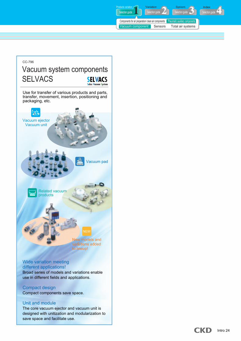
Use for transfer of various products and parts,transfer, movement, insertion, positioning andpackaging, etc.
Vacuum system componentsSELVACS
CC-796
Wide variation meeting different applications!Broad series of models and variations enable use in different fields and applications.
Compact designCompact components save space. Unit and moduleThe core vacuum ejector and vacuum unit is designed with unitization and modularization to save space and facilitate use.
NEW
Vacuum pad
Vacuum ejectorVacuum unit
Related vacuumproducts
New models andvariations addedto lineup!
NEW
Selection guideProducts variation
Selection guideVariation
Selection guideSystem
Selection guideIndex
Components for air preparation/ clean air components Pneumatic auxiliary componentsVacuum component Sensors Total air systems
NEW

Intro 25
Selection guide According to products variationSelect products according to appearance and features. indicates models added with Version 7.
Pressure sensor for air / coolant Pressure sensor for air / coolant
APS-W Rc1/8 flange
Series Port size Features Page
1066
APE
CPE
Rc1/4
Rc1/4
Setting accuracy: within 0.02MPaSetting range: 1 to 0.8MPa
Series Port size Features Page
1062
1252
Space saving and widepressure range
PSW
PPX
PPD3PPD3-SPPDPPD-SPPD-APPS2
CPD
-100kPa to 980kPa
-100kPa to 1000kPa
-100kPa to 980kPa-100kPa to 980kPa-100kPa to 980kPa-100kPa to 980kPa-100kPa to 980kPa-100kPa to 500kPa
0 to 7MPa
Series Pressure range Features Page
1090
1096
1100
112411241140114411461154
1254
Sensor-amplifier integrated type withoutdisplay miniature easy installation
Standard type, high-function type available Twin display shows pressure's "Current value"and "Setting value". 3 color digital display
PPE -100kPa to 980kPa
Sensor-amplifier integrated type without display
Sensor-amplifier integrated with display 30*Stainless steel diaphragm sensor typeSensor-amplifier integrated with display 28*Stainless steel diaphragm sensor typeWith protective BOXSensor-amplifier integrated type / separated type with displayFor coolant / other liquidsensor-amplifier integrated with display
NEWNEW
P.1057Sensors
� Reed type small pressure switch
� Pressure switch � Pressure switch
Pressure can be set over a wide rangefrom 0.05 to 0.8MPa for coolant to air
Mechanical pressure switch Page P.1059 - Electronic pressure switch Page P.1069 - Pressure sensor for air / coolant Pressure sensor for air / coolant
NEWNEW

Intro 26
Pressure sensor for airPressure sensor for air
NEW
1242
1243
APA4-BAAPA4-DAAPA4-VSAPA4-GA
Series Nozzle port size Features PageGaugeBack pressure typeReflection typeFacing type
1229
PL PEL switching element and electric wiring connection terminal,pneumatic piping terminal or power circuit are stored in box.
Series Features Page
1232
� PL switch
Without to 1.4mm
2, 3, 4, 5
0.3 to 2.0mm1, 2mm1mm1, 2, 3.2mm
Depending on manifoldA system is compact.
Stable detection by ultra low pressureAPA1Series Fixed orifice diameter Features Page
1226
APA3
Series Element set Features Page
1226
Series Features
Features
Page
Series Page
DPS
K-005
Series Differential pressure Features Page
1240Fine differential pressure switch combines pneumaticbridge circuit and electric comparison circuit5kPa
Related products when using air sensor
APA6 Related products when using air sensor
GPS2MGPS2
UGPS2
HPSMHPS
UHPS
DiscreteManifold type (2 stations to 5 stations)
ø0.5, 0.7ø0.5, 0.7
ø0.5, 0.7
Series Orifice Features Page11721177
1180
TLPSMTLPS
UTLPS
DiscreteManifold type (2 stations to 5 stations)
ø0.3ø0.3
Solenoid valve with needle, regulatorintegrated general purpose unit typeø0.3
Series Orifice Features Page12001204
1208
Solenoid valve with needle, regulatorintegrated general purpose unit type
DiscreteManifold type (2 stations to 5 stations)
ø0.5, 0.7, 1.0ø0.5, 0.7, 1.0
ø0.5, 0.7, 1.0
Series Orifice Features Page11861190
1194Solenoid valve with needle, regulatorintegrated general purpose unit type
Series Measuring range Features Page
1158DP1000 Appropriate for preventivemaintenance of pneumatics system
0 to 0.2MPa±3%F.S.
Pressure sensor for air
� Detection nozzle
� Switching element
� Switching element, manifold
� Related products (filter)
� Related products (piping instrument)
� SEPEL switch
� Contact confirmation switch (gap switch)
� Cutting tool broken detecting switch
� Close contact confirmation switch
� Electronic differential pressure switch
Page P.1221 - Pressure sensor for air
Air sensor (PEL systems)Electronic differential pressure switch Page P.1158Pressure sensor for air
Contact / close contact conf. / cutting tool broken detecting switch Page P.1165 - Pressure sensor for air
NEWSelection guide
Products variation
Selection guideVariation
Selection guideSystem
Selection guideIndex
Components for air preparation/ clean air components Pneumatic auxiliary componentsVacuum component Sensors Total air systems
Intro 27
Selection guide According to products variationSelect products according to appearance and features. indicates models added with Version 7.
P.1057Sensors
1362
1340
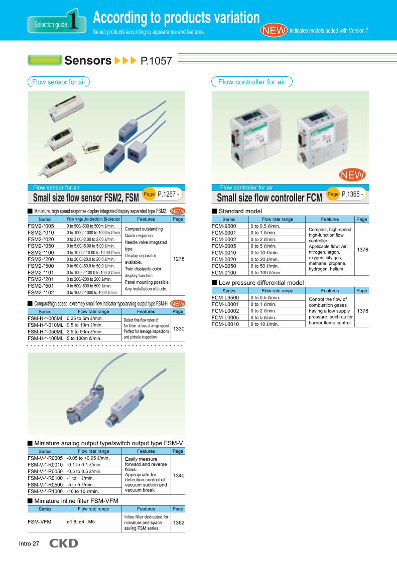
Easily measureforward and reverseflows.Appropriate fordetection control ofvacuum suction andvacuum break
FSM-V-*-R0005FSM-V-*-R0010FSM-V-*-R0050FSM-V-*-R0100FSM-V-*-R0500FSM-V-*-R1000
Series Flow rate range Features Page� Miniature analog output type/switch output type FSM-V
Inline filter dedicated forminiature and spacesaving FSM series
FSM-VFM ø1.8, ø4, M5
Series Flow rate range Features Page� Miniature inline filter FSM-VFM
1330
FSM-H-*-005MLFSM-H-*-010MLFSM-H-*-050MLFSM-H-*-100ML
Series Flow rate range Features Page� Compact/high speed, extremely small flow indicator type/analog output type FSM-H
Detect fine flow rates of1mR/min. or less at a high speed.Perfect for leakage inspectionsand pinhole inspection
1376
FCM-9500FCM-0001FCM-0002FCM-0005FCM-0010FCM-0020FCM-0050FCM-0100
Series Flow rate range Features Page
Compact, high-speed,high-function flowcontroller.Applicable flow: Air,nitrogen, argon,oxygen, city gas,methane, propane,hydrogen, helium
1376
FCM-L9500FCM-L0001FCM-L0002FCM-L0005FCM-L0010
Series Flow rate range Features Page
Control the flow ofcombustion gaseshaving a low supplypressure, such as forburner flame control.
1278
FSM2-*005FSM2-*010FSM2-*020FSM2-*050FSM2-*100FSM2-*200FSM2-*500FSM2-*101FSM2-*201FSM2-*501FSM2-*102
Series Flow range Uni-direction / Bi-direction Features Page� Miniature, high speed response display integrated/display separated type FSM2
Compact outstanding Quick response Needle valve integratedtype. Display separatoravailable. Twin display/bi-colordisplay functionPanel mounting possible. Any installation attitude.
-0.05 to +0.05R/min.-0.1 to 0.1R/min.-0.5 to 0.5R/min.-1 to 1R/min.-5 to 5R/min.-10 to 10R/min.
0.25 to 5mR/min.0.5 to 10mR/min.2.5 to 50mR/min.5 to 100mR/min.
0 to 500/-500 to 500mR/min.0 to 1000/-1000 to 1000mR/min.0 to 2.00/-2.00 to 2.00R/min.0 to 5.00/-5.00 to 5.00R/min.0 to 10.00/-10.00 to 10.00R/min.0 to 20.0/-20.0 to 20.0R/min.0 to 50.0/-50.0 to 50.0R/min.0 to 100.0/-100.0 to 100.0R/min.0 to 200/-200 to 200R/min.0 to 500/-500 to 500R/min.0 to 1000/-1000 to 1000R/min.
0 to 0.5R/min.0 to 1R/min.0 to 2R/min.0 to 5R/min.0 to 10R/min.0 to 20R/min.0 to 50R/min.0 to 100R/min.
0 to 0.5R/min.0 to 1R/min.0 to 2R/min.0 to 5R/min.0 to 10R/min.
� Standard model
� Low pressure differential model
NEWNEW
NEWNEW
NEW
Page P.1267 - Flow sensor for air
Small size flow sensor FSM2, FSM
Flow controller for airFlow sensor for air
Page Flow controller for air
Small size flow controller FCM P.1365 -
NEWNEW
NEWNEW

Intro 28
WFK3000
WFK5000
WFK6000
WFK7000
Series Flow measuring range Features Page
1470
1474
1478
1482
� Karman's vortex type
Compact / componentintegrated type
Modular design type
Standard type
Large flow rate type
PFD-501PFD-102PFD-202PFD-402PFD-802PFD-163
Series Flow rate range Features Page
1440
� Display separate type PFD
Easily detect the flowof compressed air withtotal accuracy ±4%F.S.and easily measureforward and reverseflows.
PFK-501PFK-102PFK-202PFK-402PFK-802
Series Flow rate range Features Page
1446
� Display separate type tester kit PFK
25 to 500R/min.(normal)50 to 1000R/min.(normal)100 to 2000R/min.(normal)200 to 4000R/min.(normal)400 to 8000R/min.(normal)800 to 16000R/min.(normal)
25 to 500R/min.(normal)50 to 1000R/min.(normal)100 to 2000R/min.(normal)200 to 4000R/min.(normal)400 to 8000R/min.(normal)
Measuring componentwith air flow rateimmediate flowmeasuring possible inkit field
1.0 to 8.0, 3.0 to 27R/min.
1.0 to 8.0, 3.0 to 27R/min.10 to 50, 20 to 100, 40 to 200R/min.
0.5 to 40,1.5 to 12R/min.
NEW
NEW
1414
1418
1422
PF500FPF1000FPF2000FPF4000FPF8000FPF16000F
Series Flow rate range Features Page� Display integrated type PF-F
Integrated display canbe turned to matchmounting posture.Safe design canwithstand water drops.
PFU500FPFU1000FPFU2000F
Series Flow rate range Features Page� Display integrated type modular design type PFU-F
Flow sensor for air
25 to 500R/min.(normal)50 to 1000R/min.(normal)100 to 2000R/min.(normal)200 to 4000R/min.(normal)400 to 8000R/min.(normal)800 to 16000R/min.(normal)
25 to 500R/min.(normal)50 to 1000R/min.(normal)100 to 2000R/min.(normal)
Dock filter and regulatorto this unit type withmodule connections.
NEWNEW
Flow sensor for water Page P.1455Page P.1405 - Flow sensor for air
Flow sensor for compressed air (FLUEREX)
Flow sensor for air Flow sensor for water
PageFlow sensor for air
Flow sensor for compressed air (FLUEREX) P.1431 -
Selection guideProducts variation
Selection guideVariation
Selection guideSystem
Selection guideIndex
Components for air preparation/ clean air components Pneumatic auxiliary componentsVacuum component Sensors Total air systems
NEW
NEW

Intro 29
Selection guide According to products variationSelect products according to appearance and features. indicates models added with Version 7.
P.1487Total air systems
PXVPC*PXPPR*,PX*PXB-MZB2,ZB4PXB-BPXCPXCPXCZCK
Air lightAir counterFoot switchElement and sensorPushbutton switch, switch body (set screw type)Switch headPushbutton switch, switch body (separate type)Miniature limit switchCompact limit switchLimit switchRotary head lever actuator
Series Type Page
15381539153915411542154315441546154715481549
PS*PR*,PL*PZUPL*PL*,PZM
PLCRelay typeRelay type sub-baseIntegrated type (logic element)Line type (logic element)
Series Type Page
15321533153415361537
Series Working pressure range Features Page
1526
� Air timer
RTD-3A 0.25 to 0.8MPa Delay time MAX. 30 seconds
ø4 nylon tube used for piping
ø4 nylon tube used for piping
Series Working pressure range Features Page
1527
� Pressure switch
PE-1 0.2 to 0.7MPa
Series Working pressure range Features Page
1527
� Air light
AL-* 0.05 to 0.8MPa
Series Working pressure range Features Page
� Small air light
Series Port size Features Page
1494
� Small mechanical valve
MS ø4, Rc1/8 Compact, large flow
No intermediate bleedingSeries Port size Features Page
1508
� Medium mechanical valve
MM ø4, Rc1/8
Series Port size Features Page
1520
� Large mechanical valve
MAVL Rc1/4
Total air system (gamma system)
Page P.1529 -Total air system (gamma system)
PLC
Page P.1538 - Total air system (gamma system)
Signal controllers
Total air system
Detector Page P.1490 - Total air system
Page P.1491 -Total air system
Circuit device
Insert into ø4 push-in joint 1528SAL-* 0.25 to 0.8MPa
Pressurized from 3 directions,and used as NO, NC,or distributor
NEWNEW

Intro 30
The series listed in this catalog have undergone a model changeover with this new series. Consider using the new series when making a selection.
� Refrigerating type dryerGX3100, GX5100, GX8100
� Refrigerating type dryerGX3100D, GX3200, GX5200, GT5000
Old Series New Series
� Quick exhaust valveQEV
� Quick exhaust valveQEV2
Old Series New Series
� Medium main line filterAF1000
� Medium main line filterAF2000
Old Series New Series
� Shuttle valveSHV
� Shuttle valveSHV2
Old Series New Series
� Flow sensor for compressed airPF-D
� Flow sensor for compressed airPFD
Old Series New Series
� Small size flow sensorFSM
� Small size flow sensorFSM2
Old Series New Series
Guide in model changeNEW

Intro 31
Guide in recommended substitute part
Production of the following series listed in this catalog has been discontinued. Please consider using the recommended substitute part when making a selection.
Production of the following series listed in this catalog has been discontinued. Please consider using the recommended substitute part when making a selection.
Discontinued Recommended substitute partVacuum componentsVacuum devices
Vacuum componentsSELVACS
Discontinued Recommended substitute part (Catalog)Electronic regulator / nozzle flapper typeER150,170,310,350,380
Electro-pneumatic regulatorEV/EVD Series
Discontinued Recommended substitute partRefrigerating air dryerRD (M) 2001 to 2015
Refrigerating air dryerRD (M) 1003 to 1011
Refrigerating air dryerRD (M) 1015
Refrigerating air dryerGX4103 (E) to 4106 (E)
Refrigerating air dryerGX4108 (E) to 4137 (E)
Refrigerating air dryerGX6003 to 6015
Refrigerating air dryerGX5100 Series
Refrigerating air dryerGX3106 to 3111
Refrigerating air dryerGX3115 to 3137
Refrigerating air dryerGK3100 series
Desiccant type air dryer4112 to 4132-*C
Automatic drainDB3002E
Refrigerating air dryerGX5200 Series
Precision control dryerRD-*PRT Series
Refrigerating air dryerRD7000 Series
Wilco-matic air filter1404
Interface valve / detectorR-IF
Circulation type water cooling refrigeratorHYW Series
Oil indicator6509,6510
Refrigerating air dryerGK3100D Series
Refrigerating air dryerGK3200 Series
Refrigerating air dryerGK5100 Series (No substitution products for E type)
Refrigerating air dryerGX5200Series (No substitution products for E type)
Refrigerating air dryerGX5200Series (according to conditions)
Refrigerating air dryerGX5200 Series
Refrigerating air dryerGK3100D Series
Refrigerating air dryerGX3200 Series
Refrigerating air dryerGK3100D series
Desiccant type air dryerSHD series
Automatic drainDB3003
� Vacuum ejectorVacuum unit
� Vacuum pad � Related vacuum products
Vacuum System Components (CatalogNo.CC-796)
No substitution products
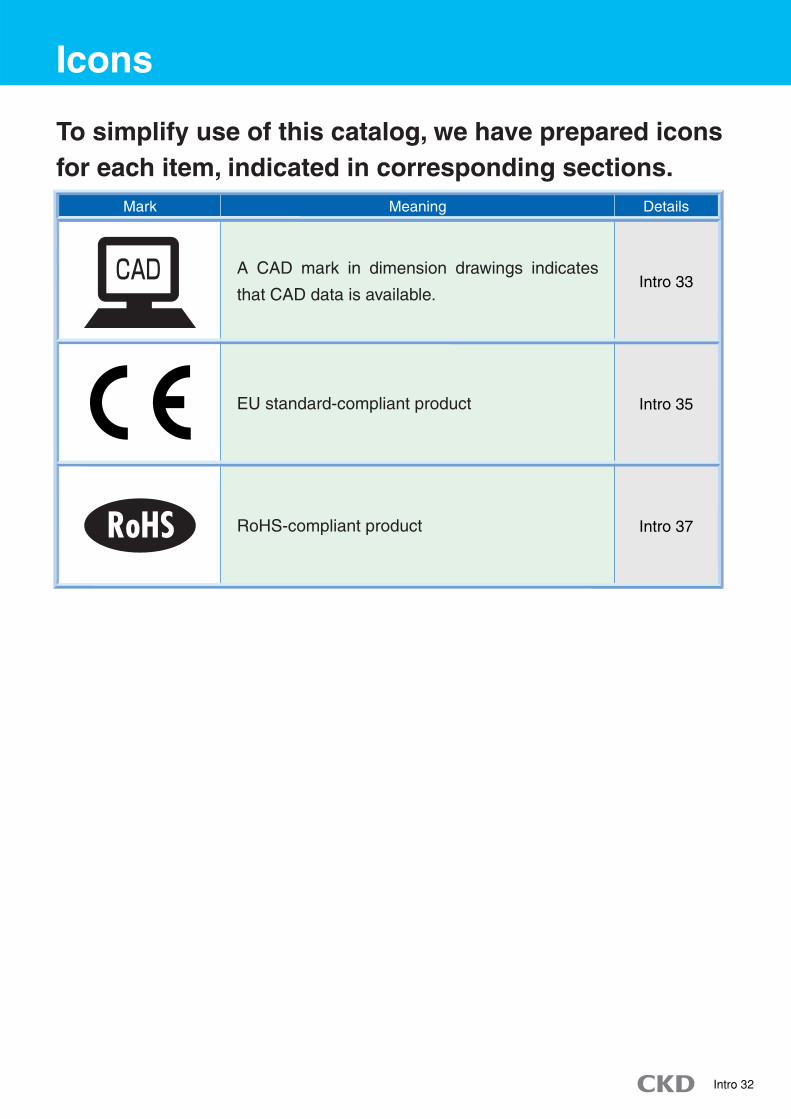
Intro 32
Icons
A CAD mark in dimension drawings indicates
that CAD data is available.
RoHS-compliant product
EU standard-compliant product
Mark Meaning Details
Intro 33
Intro 37
Intro 35
To simplify use of this catalog, we have prepared iconsfor each item, indicated in corresponding sections.

Intro 33
CKD Electronic Catalog Guide (CAD DATA)
Using and ordering the Electronic Catalog
CKD Electronic Catalog Contents
The CKD Electronic Catalog is a collection of CAD drawings including dimensions drawings (CAD data) related
to pneumatic components and control components. This data is provided on CD-ROM to aid in CAD design.
Please contact your CKD Sales person or our nearest sales office to order this CD.
The following data and software are recorded on CD-ROM "CAD DATA 2006". � Pneumatic component and control component figure data (DXF / MICRO CADAM / DMNDOS)� README. TXT (Use and precautions) � List.xls (DXF CAD data list)� Kensaku.exe (CAD drawing search program) � List_mc.xls (MC CAD data list)
DXF data an be used from
CKD website Component Products Catalog/CAD data>
Downloading from the internet
� Indicate the following information when placing your order:1 CAD software name and version 2 OS name
There are three types of CD-ROM depending on the recorded CAD software and
OS type. Be sure to indicate the name of the CAD software and OS you are using.
� Compatible CAD types1 DXF
2 MICRO CADAM Ver1.9
3 DMNDOS (MICRO CADAM DOS ver.)

Intro 34
CKD Electronic Catalog Guide (CAD DATA)
Searching from this catalog
How to use Electronic Catalog
Searching the Electronic Catalog Filename
CAD data is available for items with a CAD mark in dimensions.
Searching from CD-ROM
� Operating the CAD � Confirmation before use � Electronic Catalog file list
When the CD-ROM is set in the drive, the “CAD Data Search Software” will start up, and the search screen shown on the left will open. (*1) The required CAD data can be searched and saved onto the hard disk.*1: If the automatic play function is not set,
start up with “Kensaku.exe” on the CD-ROM. This software does not need to be installed.
Read the README.TXT file on the CD-ROM before starting use. Information on� How to use the CKD Electronic Catalog� Precaution� For version information,confirm "README.txt" contained in CD-ROM.
Refer to� List.xls� List_mc.xlson the CD-ROM for the latest files of Electronic Catalog files.
Contact the CAD maker for details on operating CAD -� Reading files� Creating graphics� Usable data formats

Intro 35
CE Marking
CE Marking
�The CE Marking attests that the product satisfies all EC Directive requirements to which it is subject.
�CE Marking is a passport for products to the EU Products with the CE Marking can be freely distributed within the EU.
�Machines exported to the EU must comply with Machinery Directives, EMS Directives, and Low-Voltage Directives, etc. In principle, CE marking must be indicated on the final product marketed and, basically, built-in components do not require CE Markings. If compliance of built-in parts (CKD products) with EU Standards can be verified, CE Marking of the final product (customer's machine product) can be easily obtained.
: Indicated on EU Standard-compatible products.
CKD supports our customer's machine products CE Markingwith a wide range of EU Standard-compatible components.

Intro 36
CE Marking
Details on EC Directives
CKD EU standard-Compliant Parts
Directive Requirements Application
Requirements forMachine Safety
Safety regarding electricity,such as electrical shock
Safety regarding vesselleakage and explosions
Measures against electromagnetic interference emission (EMI emission) and electromagnetic interference elimination performance (EMS immunity).
A total of 28 countries require CE Marking compliance, including 25 EuropeanUnion (EU) countries and three European Free Trade Association (EFTA) countries. U.K., Ireland, France, Belgium, Denmark, Netherlands, Italy, Germany
Luxembourg, Portugal, Spain, Greece, Sweden, Finland, Austria,Poland, Hungary, Czech, Slovakia, Lithuania, Latvia, Estonia, Slovenia,Malta, Cyprus (Only Southern Republic of Cyprus)
Norway, Iceland, Liechtenstein (Excluding Switzerland)EFTA members
EU members
� Devices that generate electromagnetic interferenceor that are affected by electromagnetic interference
� Machine operating at 50 to1000 VAC and 75 to1500 VDC
� Welded vessel having sum (PV/S)of maximum working pressure andvolume exceeding 50 bar/liter
� Machine having a drive sectionComponents such as solenoid valves are not subject to this compliance, but the user obtains CE Marking certification easier by complying with Standards.
Refer to the CKD web site for the latest information. Home Page Address http://www.ckd.co.jp/
Depending on specifications and detailed model combinations, certified parts may not be available. Contact your CKD Sales Representative for details. Certified part model: Indicated with-ST at the end of the model.
CKD's main components, such as the solenoid valve, sensors, and direct drive actuator, must comply with the Directives below. Many models already comply with EU Standards.
Machinery Directives(89/392/EEC)
EMC Directive(89/336/EEC)
Low-Voltage Directive(73/23/EEC)
Simple PressureVessel Directive
(87/404/EEC)
Solenoid valves composed of a simple solenoid are not affected by electromagnetic interference, but the user can obtain CE Marking certification easier by complying with Standards.
The CKD air tank (AT type) does not comply with this directive, and cannot be exported to the EU.
3/5R
2B
2B
2B
2B
1P
4A
12/14
3/5R
2B
2B
2B
2B
1P
4A
12/14

Intro 37
CKD RoHS Compliance
CKD's Environment Policy
Based on the CKD Environment Policy enacted in 2001, CKD has been promoting company-wide environment management activities to protect the global environment.
CKD's theme is to develop environmentally friendly products.
1 Development of sales of environment load reducing products2 Reduction of environment-polluting substances3 Promotion of energy conservation and resource reduction4 Waste reduction
CKD's Environment Policy
�CKD started compliance with RoHS Directives on July, 2006.
�RoHS-compliant products reduce the load on the environment and ensure distribution throughout the EU.
RoHS is the abbreviation for Restriction Of the use of certain Hazardous Substances in electrical and electronic equipment. This is the directive prohibiting use of certain hazardous substances issued by the EU.

Intro 38
CKD RoHS Compliance
CKD's compliance with RoHS
Technical Data
Products subject to RoHS Directions fall within the Applicable scope in , below.
While CKD's components are not included in this applicable range, we have
positioned the reduction of environment-polluting chemical s as high-priority. From
July 2006, we have sequentially enforced RoHS Compliance of our key products.
These products are indicated with the "RoHS-compliant" mark in this manual.
Applicable scope
Details of Directive
EU Directives related to Waste Electrical and Electronic Equipment (WEEE) and Restriction on Hazardous Substances Directive (RoHS) have been enacted by the EU.
Enactments of WEEE Directive and RoHS Directive
This directive eliminates waste electrical and electronic equipment and reduces waste through reuse and recycling, etc.
WEEE Directive(Directive 2002/96/EC of 27 January 2003 on waste electrical and electronic equipment)
This directive assimilates laws related to limiting the use of hazardous substances in electrical and electronic devices set forth by each EU member state, contributes to the protection of human health, and provides sufficient means for processing and recycling waste electrical and electric products.
RoHS Directive(Directive 2002/95/EC of 27 January 2003 on the restriction of the use of certain hazardous substances in electrical and electronic equipment)
Restricted substances
� Lead, mercury, cadmium, hexavalent chromium, polybrominated biphenyls (PBB)
� Polybrominated diphenyl ether (PBDE)
Import of electrical and electronic equipment containing the above substances into
the EU was prohibited as a rule from July 1, 2006.
Note: Stock in distribution is being sequentially changed to RoHS Compliance.
1 Large household appliances2 Small household appliances3 IT and telecommunications equipment4 Consumer equipment
5 Lighting equipment6 Electric tools, excluding large fixed industrial tools7 Toys, leisure and sporting goods8 Vending machines

Intro 39
According to variationSelection guideSelection guide
Copper and PTFE freeSeries / model Port size Remarks Page
Rc1/8 to Rc1Rc1/8 to Rc1Rc1/8 to Rc1Rc1/8 to Rc1Rc1/8 to Rc1Rc1/8 to Rc1
Rc1/8 to Rc1
Rc1/4 to Rc1
Rc1/8 to Rc1Rc1/8 to Rc1
Rc1/8 to Rc1
Rc1/8 to Rc1
Rc1/8 to Rc1Rc1/8 to Rc1
Rc1/8 to Rc1
Rc1/8 to Rc1/2R1/8R1/4
Rc3/8 to Rc2M3, M5
M3 to R1/2M3 to R1/2
Rc1/8 to Rc1/2R1/8 to R1/2R1/4 to R1
M3 to Rc(R)1/8M3 to R1/2ø3.2 to ø15
Rc1/8 to Rc1
Rc1/8
Pneumatic components for Braun tube manufacturing lines.
Copper and PTFE free as standard
Copper and PTFE free as standard
Copper and PTFE free as standard(Refer to model no.)
Copper and PTFE free as standard(Refer to model no.)
Copper and PTFE free as standard
Copper and PTFE free as standard
Copper and PTFE free as standard
Copper and PTFE free as standard
Copper and PTFE free as standard
Copper and PTFE free as standard
Copper and PTFE free as standard
Copper and PTFE free as standard
Copper and PTFE free as standard
500 500 500 500 500 500
324
330
501502
503
504
505506
507
408508508244834842846856878878922930
1012
404
1140
Filt
er /
regu
lato
r (F
.R.L
.)P
neum
atic
aux
iliar
y co
mpo
nent
sS
enso
rs
C**00-W -TP6C**10-W -TP6C**20-W -TP6C**30-W -TP6C**40-W -TP6C**50-W -TP6
C*060-W
C*070-W
W*000-W -TP6W*100-W -TP6
F*000-W
M*000-W
R*000-W -TP6R*100-W -TP6
L*000-W
V*000-WG49D -P6G59D -P6FA*31SC-*SC3W-P6SC3U-P6SC1-P6SLWSLFGW -P6F.U.NU.KX.SR
P*100-W -P6
PPD
F.R.L. combination
W.L. combination
F.R. combination
F.M.R. combination
W.M. combination
R.M. combination
F.M. combination
F.F.M. combination
Filter / regulator
Reverse filter / regulator
Air filter
Oil mist filter
Regulator
Reverse regulator
Lubricator
Shut-off valve
General purpose pressure gauge
General purpose pressure gauge
Exhaust cleaner
Miniature speed control valve
Speed control valve, elbow type
Speed control valve, universal type
Speed control valve
Silencer
Silencer
Miniature joint
Joint
Tube
Mechanical pressure switch(Reed type small pressure switch)
Electronic pressure switch(Pressure switch)
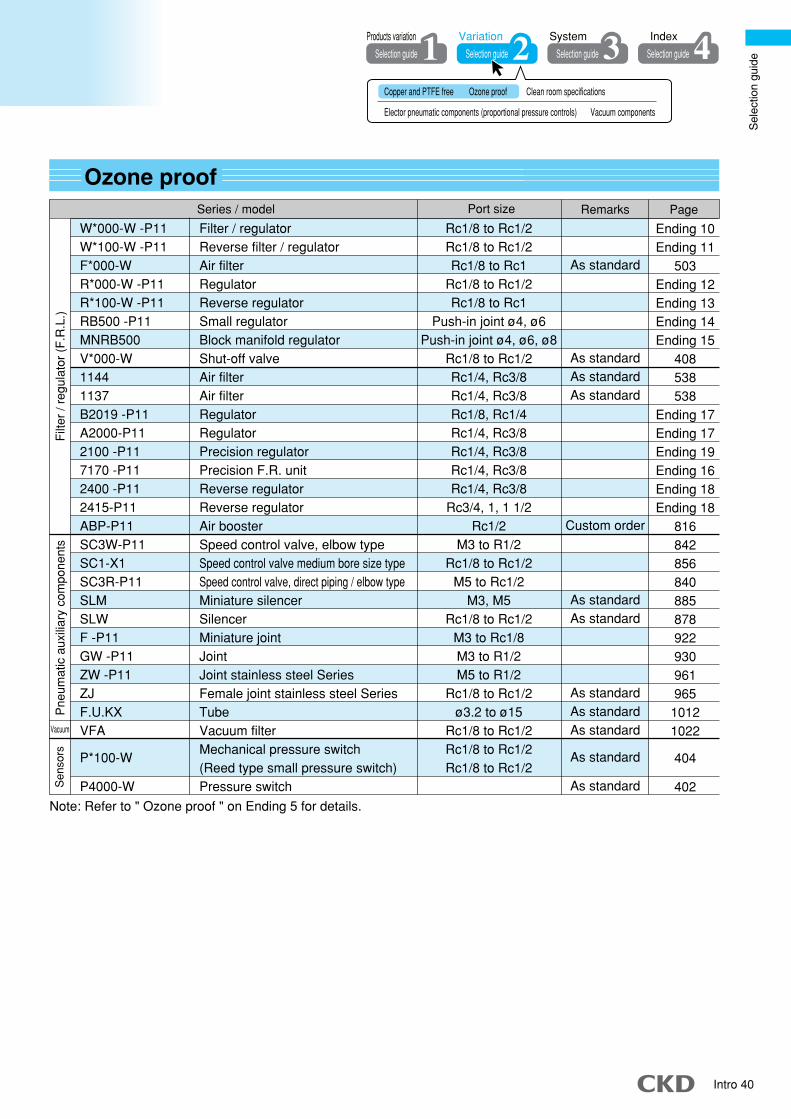
Sel
ectio
n gu
ide
Intro 40
Copper and PTFE free Ozone proof Clean room specifications
Elector pneumatic components (proportional pressure controls) Vacuum components
Selection guide Selection guide Selection guide Selection guide
IndexSystem VariationProducts variation
Ozone proofSeries / model Port size Remarks Page
W*000-W -P11W*100-W -P11F*000-WR*000-W -P11R*100-W -P11RB500 -P11MNRB500V*000-W11441137B2019 -P11A2000-P112100 -P117170 -P112400 -P112415-P11ABP-P11SC3W-P11SC1-X1SC3R-P11SLMSLWF -P11GW -P11ZW -P11ZJF.U.KXVFA
P*100-W
P4000-W
Filter / regulatorReverse filter / regulatorAir filterRegulatorReverse regulatorSmall regulatorBlock manifold regulatorShut-off valveAir filterAir filterRegulatorRegulatorPrecision regulatorPrecision F.R. unitReverse regulatorReverse regulatorAir boosterSpeed control valve, elbow typeSpeed control valve medium bore size typeSpeed control valve, direct piping / elbow typeMiniature silencerSilencerMiniature jointJointJoint stainless steel SeriesFemale joint stainless steel SeriesTubeVacuum filterMechanical pressure switch(Reed type small pressure switch)Pressure switch
Rc1/8 to Rc1/2Rc1/8 to Rc1/2Rc1/8 to Rc1
Rc1/8 to Rc1/2Rc1/8 to Rc1
Push-in joint ø4, ø6Push-in joint ø4, ø6, ø8
Rc1/8 to Rc1/2Rc1/4, Rc3/8Rc1/4, Rc3/8Rc1/8, Rc1/4Rc1/4, Rc3/8Rc1/4, Rc3/8Rc1/4, Rc3/8Rc1/4, Rc3/8
Rc3/4, 1, 1 1/2Rc1/2
M3 to R1/2Rc1/8 to Rc1/2
M5 to Rc1/2M3, M5
Rc1/8 to Rc1/2M3 to Rc1/8M3 to R1/2M5 to R1/2
Rc1/8 to Rc1/2ø3.2 to ø15
Rc1/8 to Rc1/2Rc1/8 to Rc1/2Rc1/8 to Rc1/2
As standard
As standardAs standardAs standard
Custom order
As standardAs standard
As standardAs standardAs standard
As standard
As standard
Note: Refer to " Ozone proof " on Ending 5 for details.
Ending 10Ending 11
503Ending 12Ending 13Ending 14Ending 15
408538538
Ending 17Ending 17Ending 19Ending 16Ending 18Ending 18
816842856840885878922930961965
10121022
404
402
Filt
er /
regu
lato
r (F
.R.L
.)P
neum
atic
aux
iliar
y co
mpo
nent
sS
enso
rs
Vacuum

Intro 41
Clean room specificationsSeries / model Port size Remarks Catalog No./page
W*000-W -P7*
W*100-W -P7*
F *000-W -P7*
M*000-W -P7*
R *000-W -P7*
R *100-W -P7*
FCS500 -P9*
FCS1000-P9*
FAC
RC2000 -P90
1019/1144 -P80/P90
1219/1244 -P80/P90
2619-P80/P9*
RP*000 -P70
G49D-6 -P70/P9*
G59D-8 -P70/P9*
GA400-8 -P90
F -P80
GW -P7*/P80
GWJ-P7*/P80
ZW -P80
ZW -P90
SC3R-P7*
SC3W-P7*
SC1-P7*
SCL2-P7*
SCD2-P7*
SCL2-N-P7*/P80
CHL -P7*
CHV2 -P7*/P80
2QV -P70
UP -9102 -P80
UP -**** -P80 -F1
NU
Rc1/8 to Rc1/2Rc1/8 to Rc1/2Rc1/8 to Rc1Rc1/8 to Rc1Rc1/8 to Rc1Rc1/8 to Rc1
ø4 to ø8, Rc1/8, Rc1/4ø8 to ø12, Rc1/4, Rc3/8, Rc1/4, Rc3/8ø4 to ø10, R1/8 to R1/2, Rc3/8, Rc1/2
Rc1/4 to Rc1/2Rc1/8 to Rc3/8Rc1/8 to Rc3/8Rc1/8, Rc1/4Rc1/4, Rc3/8
R1/8R1/4Rc1/4
M3 to Rc1/8M3 to R1/2
M3 to Rc (R)1/8M3 to R1/2
R1/8 to R1/2M5 to Rc1/2M3 to R1/2
Rc1/8 to Rc1/2
ø1.8 to ø12
ø1.8 to ø12
ø4 to ø8M5, ø4, ø6
Rc1/8 to Rc1 1/2ø4 to ø12, R1/8 to R1/2
ø1.8ø3.2 to ø12ø3.2 to ø12
Particle occurrence prevented pneumaticcomponents for clean room
Filter regulator
Reverse filter / regulator
Air filter
Oil mist filter
Regulator
Reverse / regulator
Inline clean filter
Inline clean filter
Clean exhaust filter
Clean regulator
Air filter (5μm)
Micro alescer (0.1μm)
Regulator
Precision regulator
General purpose pressure gauge
General purpose pressure gauge
Differential pressure gauge
Miniature joint
Joint
Small size joint
Joint stainless steel type
Tightening joint stainless steel series
Speed control valve, direct piping / elbow type
Speed control valve, elbow type
Speed control valve medium bore size type
Speed control valve line type
(push-in joint)
In/out speed control valve, inline type
(push-in joint)
Needle valve (push-in joint)
Small check valve with push-in joint
Check valve (check valve)
Quick exhaust valve
Fiber tube
Antistatic tube
Urethane tube
* Refer to catalog No. CB-033SA Pneumatic components for clean room specifications.
CB-033SA
*
CB-033SA
*
According to variationSelection guideSelection guide
Filt
er /
regu
lato
r (F
.R.L
.)P
neum
atic
aux
iliar
y co
mpo
nent
s

Sel
ectio
n gu
ide
Intro 42
Elector pneumatic components (proportional pressure controls)Series / model Features Remarks Page
EVD-1*00EVD-3*00EV2000EV2100VEV0000EVSMEVT3AP2AF3AFAPCPIPPS2 controller
PPS2 switch
PSWPPEPPDPPD3
Pressure control
Pressure control
Pressure control
Pressure control (vacuum)
Pressure control
Pressure control
Pressure control
Pressure control
Flow rate control
Flow rate control
Dedicating control component for proportional valve
Interface for proportional valve
Controller for electro pneumatics
Sensor-amplifier integrated type without display
Sensor-amplifier integrated type without display
Sensor-amplifier integrated type with display
Sensor-amplifier integrated type / separated type with display
Proportional pressure control is the generic name for theelectronic pneumatic pressure application components.
736740760771765768778800800800804808
1154
11501096109011401124
Sensor-amplifier integrated type/ separated type with display
Clean room specificationsSeries / model Remarks Catalog No./page
Particle occurrence prevented pneumaticcomponents for clean room
* Refer to catalog No. CB-033SA Pneumatic components for clean room specifications.
PPD3 -P7*/P8*PPD3 -S -P7*/P8*/P9*PPE -P70/P80PPS2 -P70/P80PPS2 -P70/P80FSM2 -P70/P80EV2000 -P7*/P8*EV0000 -P7*/P8*EVS -P7*/P8*EV2100V-P70MEVT -P7*/P8*
Electronic pressure switch
Compact electronic pressure switch
Electronic pressure switch
Electronic pressure controller
Small size flow sensor
Electro pneumatic regulator
Electro pneumatic regulator
Thin electro pneumatic regulator
Digital electro-pneumatic regulator
Digital electro-pneumatic regulator
Electro pneumatic regulator
Electro pneumatic regulator
Electro pneumatic regulator
Electro pneumatic regulator
Thin electro pneumatic regulator
Proportional control valve
Proportional control valve
Proportional control valve
Controller
Interface
Pressure controller
Electronic pressure switch
(Pressure switch)
CB-033SA
*
Copper and PTFE free Ozone proof Clean room specifications
Elector pneumatic components (proportional pressure controls) Vacuum components
Selection guide Selection guide Selection guide Selection guide
IndexSystem VariationProducts variation
Sen
sors
Electr
o-pne
umati
c reg
ulator
Pre
ssur
e co
ntro
lP
ress
ure
dete
ctio
n
Port size
Rc1/8, ø6 push-in joint
R1/8, ø6 push-in joint
Rc1/8
Rc1/8
ø1.8, ø4, ø6, Rc1/8, Rc1/4, M5
Rc1/4
M5
M5
Rc1/4
ø4, ø6 push-in joint
Max. flow rate 400 (R/min.)Max. flow rate 1500 (R/min.)Max. flow rate 800 (R/min.)Max. flow rate 120, 150 (R/min.)Max. flow rate 2, 6 (R/min.)Max. flow rate 2, 6 (R/min.)Max. flow rate 2, 6 (R/min.)
Max. effective sectional area 5 to 20mm2
Max. effective sectional area 3 to 17mm2
Pneumatics / vacuum
Pneumatics / vacuumPneumatics / vacuumPneumatics / vacuumPneumatics / vacuum

Intro 43
According to variationSelection guideSelection guide
Vacuum componentsSeries / model Port size / characteristics
Vacuum filter
Vacuum filter
Vacuum regulator
Electro pneumatic regulator
Rc1/8 to Rc1/2
Rc1/4, 3/8Max. flow rate 120 / 150 (mm2)
Pneumatic components for vacuum equipment.
102212421026
CC-796A
12261240
109011401124
Sen
sors
Filte
r / re
gula
tor
Sensor-amplifier integrated type/ separated type with display
VFA1000,3000,4000K-005VRA2000EV2100V
APA1DPS
PPS2
PSWPPEPPDPPD3
Refer to the "Vacuum System Components SELVACS" (No. CC-796A) catalog for details onthe vacuum ejector/vacuum unit, vacuum pads and vacuum related components.
Air sensor
SEPEL switch
Electronic pressure switch
(Pressure switch)
Pneumatics / vacuum
Pneumatics / vacuumPneumatics / vacuumPneumatics / vacuumPneumatics / vacuum
Sensor-amplifier integrated type without display
Sensor-amplifier integrated type without display
Sensor-amplifier integrated type with display
Sensor-amplifier integrated type / separated type with display
Pressure control (vacuum)
Remarks Catalog No. / Page

Sel
ectio
n gu
ide
Intro 44
Copper and PTFE free Ozone proof Clean room specifications
Elector pneumatic components (proportional pressure controls) Vacuum components
Selection guide Selection guide Selection guide Selection guide
IndexSystem VariationProducts variation

Intro 45
System selection 2
Conditions are set easily even by beginners.
According to systemSelection guideSelection guide
�Selecting the selection methodIn this section "Selection 3", the optimum model is selected from predetermined conditions.
Selecting from cylinder bore sizeand operation speed
Intro 46
Selecting from load valueand operation time
Intro 57
System selection 1
Conditions
When bore size andcylinder operation speed
are determined.
When load value andoperation time
are determined.
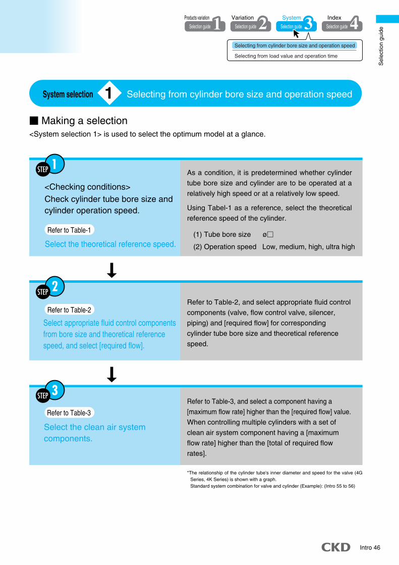
Sel
ectio
n gu
ide
Intro 46
� Making a selection
Selecting from cylinder bore size and operation speed
<System selection 1> is used to select the optimum model at a glance.
1 System selection
Selection guide Selection guide Selection guide
IndexSystem Variation
Selection guide
Products variation
Selecting from cylinder bore size and operation speed
Selecting from load value and operation time
<Checking conditions>Check cylinder tube bore size andcylinder operation speed.
As a condition, it is predetermined whether cylinder
tube bore size and cylinder are to be operated at a
relatively high speed or at a relatively low speed.
Using Tabel-1 as a reference, select the theoretical
reference speed of the cylinder.
Refer to Table-1
Select the theoretical reference speed.
Refer to Table-2
Select appropriate fluid control componentsfrom bore size and theoretical referencespeed, and select [required flow].
Refer to Table-2, and select appropriate fluid control
components (valve, flow control valve, silencer,
piping) and [required flow] for corresponding
cylinder tube bore size and theoretical reference
speed.
Refer to Table-3
Select the clean air systemcomponents.
Refer to Table-3, and select a component having a
[maximum flow rate] higher than the [required flow] value.
When controlling multiple cylinders with a set of
clean air system component having a [maximum
flow rate] higher than the [total of required flow
rates].
*The relationship of the cylinder tube's inner diameter and speed for the valve (4G Series, 4K Series) is shown with a graph. Standard system combination for valve and cylinder (Example): (Intro 55 to 56)
(1) Tube bore size ø�
(2) Operation speed Low, medium, high, ultra high
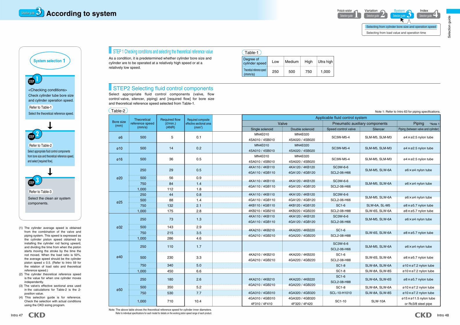
Sel
ectio
n gu
ide
Intro 47 Intro 48
ø6
ø10
ø16
ø20
ø25
ø32
ø40
ø50
SC3W-M5-4
SC3W-M5-4
SC3W-M5-4
SC3W-6-6
SCL2-06-H66
SC3W-6-6
SCL2-06-H66
SC3W-6-6
SCL2-06-H66
SC1-6
SCL2-08-H88
SC3W-6-6
SCL2-06-H66
SC1-6
SCL2-08-H88
SC3W-6-6
SCL2-06-H66
SC1-6
SCL2-08-H88
SC1-8
SC1-8
SC1-6
SCL2-08-H88
SC1-8
SCL-10-H1010
SC1-10
SLM-M5, SLM-M3
SLM-M5, SLM-M3
SLM-M5, SLM-M3
SLM-M5, SLW-6A
SLM-M5, SLW-6A
SLM-M5, SLW-6A
SLW-6A, SL-M5
SLW-6S, SLW-6A
SLM-M5, SLW-6A
SLW-6S, SLW-6A
SLM-M5, SLW-6A
SLW-6S, SLW-6A
SLW-8A, SLW-6A
SLW-8A, SLW-8S
SLW-6A, SLW-6S
SLW-8A, SLW-6A
SLW-8A, SLW-8S
SLW-10A
ø4�ø2.5 nylon tube
ø4�ø2.5 nylon tube
ø4�ø2.5 nylon tube
ø6�ø4 nylon tube
ø6�ø4 nylon tube
ø6�ø4 nylon tube
ø8�ø5.7 nylon tube
ø8�ø5.7 nylon tube
ø6�ø4 nylon tube
ø8�ø5.7 nylon tube
ø6�ø4 nylon tube
ø8�ø5.7 nylon tube
ø10�ø7.2 nylon tube
ø10�ø7.2 nylon tube
ø8�ø5.7 nylon tube
ø10�ø7.2 nylon tube
ø10�ø7.2 nylon tube
ø15�ø11.5 nylon tube
or Rc3/8 steel pipe
MN4E020
4SA020 / 4SB020
MN4E020
4SA020 / 4SB020
MN4E020
4SA020 / 4SB020
4KA120 / 4KB120
4GA120 / 4GB120
4KA120 / 4KB120
4GA120 / 4GB120
4KA120 / 4KB120
4GA120 / 4GB120
4KB120 / 4GB120
4KB220 / 4GB220
4KA120 / 4KB120
4GA120 / 4GB120
4KA220 / 4KB220
4GA220 / 4GB220
4KA220 / 4KB220
4GA220 / 4GB220
4KA220 / 4KB220
4GA220 / 4GB220
4GA320 / 4GB320
4GA320 / 4GB320
4F320 / 4F420
As a condition, it is predetermined whether cylinder bore size and cylinder are to be operated at a relatively high speed or at a relatively low speed.
Select appropriate fluid control components (valve, flow control valve, silencer, piping) and [required flow] for bore size and theoretical reference speed selected from Table-1.
STEP 1 Checking conditions and selecting the theoretical reference value
STEP2 Selecting fluid control components
Note 1: Refer to Intro 63 for piping specifications.Table-2
(1) The cylinder average speed is obtained from the combination of the valve and piping system. This speed is expressed as the cylinder piston speed obtained by installing the cylinder rod facing upward, and dividing the time from when the piston starts moving the stroke by the time the rod moved. When the load ratio is 50%, the average speed should be the cylinder piston speed x 0.5. (Refer to Intro 59 for the relation of load ratio and theoretical reference speed.)
(2) The cylinder theoretical reference speed is the value for when one cylinder moves independently.
(3) The valve's effective sectional area used in the calculations for Table-2 is the 2-position value.
(4) This selection guide is for reference. Check the selection with actual conditions using the CKD sizing program.
Note: The above table shows the theoretical reference speed for cylinder inner diameters. Refer to individual specifications for each model for details on the working piston speed range of each product.
According to systemSelection guideSelection guide
<Checking conditions>Check cylinder tube bore sizeand cylinder operation speed.
Refer to Table-1
Select the theoretical reference speed.
Refer to Table-2
Select appropriate fluid control componentsfrom bore size and theoretical reference speed,and select [required flow].
Refer to Table-3
Select the clean air systemcomponents.
Selection guide Selection guide Selection guide
IndexSystem Variation
Selection guide
Products variation
Valve Pneumatic auxiliary components
Applicable fluid control system
PipingBore size(mm)
Theoreticalreference speed
(mm/s)
Required compositeeffective sectional area
(mm2) Single solenoid Double solenoid Speed control valve Silencer Piping (between valve and cylinder)
Required flow(R/min.)(ANR)
500
500
500
250
500
750
1,000
250
500
750
1,000
250
500
750
1,000
250
500
750
1,000
250
500
750
1,000
5
14
36
29
56
84
112
44
88
132
175
73
143
215
286
110
230
340
450
180
350
530
710
0.1
0.2
0.5
0.5
0.9
1.4
1.8
0.8
1.4
2.1
2.8
1.3
2.9
3.5
4.6
1.7
3.3
5.0
6.6
2.6
5.2
7.7
10.4
MN4E010
4SA010 / 4SB010
MN4E010
4SA010 / 4SB010
MN4E010
4SA010 / 4SB010
4KA110 / 4KB110
4GA110 / 4GB110
4KA110 / 4KB110
4GA110 / 4GB110
4KA110 / 4KB110
4GA110 / 4GB110
4KB110 / 4GB110
4KB210 / 4GB210
4KA110 / 4KB110
4GA110 / 4GB110
4KA210 / 4KB210
4GA210 / 4GB210
4KA210 / 4KB210
4GA210 / 4GB210
4KA210 / 4KB210
4GA210 / 4GB210
4GA310 / 4GB310
4GA310 / 4GB310
4F310 / 4F410
*Note 1
Degree of cylinder speed
Theoretical reference speed(mm/s)
Low
250
Medium
500
High
750
Ultra high
1,000
Table-1
1System selection
Selecting from cylinder bore size and operation speed
Selecting from load value and operation time

Sel
ectio
n gu
ide
Intro 49 Intro 50
Bore size(mm)
Theoreticalreference speed
(mm/s)
Required flow(R/min.)(ANR)
Required compositeeffective sectional area
(mm2)Valve Pneumatic auxiliary components
Applicable fluid control system
PipingSingle solenoid Double solenoid Speed control valve Silencer Piping (between valve and cylinder)
*Note 1
4KA220 / 4KB220
4GA320 / 4GB320
4GA320 / 4GB320
4KA320 / 4KB320
4F320 / 4F420
4F520
4KB220 / 4F220-08
4F420-10 / 4F320-10
4KB320-10
4KB420-15 / 4F520-15
4F420-10 / 4F320-10
4KB320-10
4KB420-15 / 4F520-15
4F620-20
4KB420-15 / 4F520-15
4F620-20
4KB420-15 / 4F520-15
4F620-20
4F720-25
4KB420-15 / 4F520-15
4F620-20
4F720-20
-
SC1-6
SCL2-08-H88
SC1-8
SCL-10-H1010
SC1-10
SC1-15
SC1-8
SCL-10-H1010
SC1-10
SC1-15
SC-20A
SC1-10
SC1-15
SC-20A
SC-20A
SC1-15
SC-20A
SC-20A
SC-20A
SC1-15
SC-20A
SC-20A
SC-20A
SC-20A
SC-20A
-
SLW-6S, SLW-6A
SLW-8A, SLW-8S
SLW-10A
SLW-15A
SLW-8A, SLW-8S
SLW-10A
SLW-15A
SLW-15A
SLW-10A
SLW-15A
SLW-15A
SL-20A, SLW-20S
SLW-15A
SLW-15A
SL-20A, SLW-20S
SL-20A
SLW-15A
SL-20A, SLW-20S
SL-20A
SL-25A
SLW-15A
SL-20A
SL-20A
-
ø8�ø5.7 nylon tube
ø10�ø7.2 nylon tube
ø15�ø11.5 nylon tube
or Rc3/8 steel pipe
Rc1/2 steel pipe
ø10�ø7.2 nylon tube
ø15�ø11.5 nylon tube
or Rc3/8 steel pipe
Rc1/2 steel pipe
Rc1/2 steel pipe
ø15�ø11.5 nylon tube
or Rc3/8 steel pipe
Rc1/2 steel pipe
Rc1/2 steel pipe
Rc3/4 steel pipe
Rc1/2 steel pipe
Rc1/2 steel pipe
Rc3/4 steel pipe
Rc3/4 steel pipe
Rc1/2 steel pipe
Rc3/4 steel pipe
Rc3/4 steel pipe
Rc1 steel pipe
Rc1/2 steel pipe
Rc3/4 steel pipe
Rc3/4 steel pipe
-
(1) The cylinder average speed is obtained from the combination of the valve and piping system. This speed is expressed as the cylinder piston speed obtained by installing the cylinder rod facing upward, and dividing the time from when the piston starts moving the stroke by the time the rod moved. When the load ratio is 50%, the average speed should be the cylinder piston speed x 0.5. (Refer to Intro 59 for the relation of load ratio and theoretical reference speed.)
(2) The cylinder theoretical reference speed is the value for when one cylinder moves independently.
(3) The valve's effective sectional area used in the calculations for Table-2 is the 2- position value.
(4) This selection guide is for reference. Check the selection with actual conditions using the CKD sizing program.
<Checking conditions>Check cylinder tube bore sizeand cylinder operation speed.
Refer to Table-1
Select the theoretical reference speed.
Refer to Table-2
Select appropriate fluid control componentsfrom bore size and theoretical reference speed,and select [required flow].
Refer to Table-3
Select the clean air systemcomponents.
Note 1: Refer to Intro 63 for piping specifications.
Selection guide Selection guide Selection guide
IndexSystem Variation
Selection guide
Products variationAccording to system
1System selection
Selecting from cylinder bore size and operation speed
Selecting from load value and operation time
ø63
ø80
ø100
ø125
ø140
ø160
250
500
750
1,000
250
500
750
1,000
250
500
750
1,000
250
500
750
1,000
250
500
750
1,000
250
500
750
1,000
280
560
840
1,100
450
910
1,400
1,800
710
1,400
2,100
2,800
1,100
2,200
3,300
4,400
1,400
2,800
4,200
5,500
1,800
3,600
5,400
7,200
4.1
8.2
12.3
16.4
6.6
13.2
19.8
26.4
10.3
20.6
30.9
41.2
16.1
32.2
48.2
64.4
20.2
40.4
60.5
80.8
26.3
52.6
79.0
104.7
4KA210 / 4KB210
4GA310 / 4GB310
4GA310 / 4GB310
4KA310 / 4KB310
4F310 / 4F410
4F510
4KB210 / 4F210-08
4F410-10 / 4F310-10
4KB310-10
4KB410-15 / 4F510-15
4F410-10 / 4F310-10
4KB310-10
4KB410-15 / 4F510-15
4F610-20
4KB410-15 / 4F510-15
4F610-20
4KB410-15 / 4F510-15
4F610-20
4F710-25
4KB410-15 / 4F510-15
4F610-20
4F710-20
-
Selection guideSelection guide

Sel
ectio
n gu
ide
Intro 51 Intro 52
Bore size(mm)
Theoreticalreference speed
(mm/s)
Required flow(R/min.)(ANR)
Required compositeeffective sectional area
(mm2)Valve Pneumatic auxiliary components
Applicable fluid control system
PipingSingle solenoid Double solenoid Speed control valve Silencer Piping (between valve and cylinder)
*Note 1
(1) The cylinder average speed is obtained from the combination of the valve and piping system. This speed is expressed as the cylinder piston speed obtained by installing the cylinder rod facing upward, and dividing the time from when the piston starts moving the stroke by the time the rod moved. When the load ratio is 50%, the average speed should be the cylinder piston speed x 0.5. (Refer to Intro 59 for the relation of load ratio and theoretical reference speed.)
(2) The cylinder theoretical reference speed is the value for when one cylinder moves independently.
(3) The valve's effective sectional area used in the calculations for Table-2 is the 2- position value.
(4) This selection guide is for reference. Check the selection with actual conditions using the CKD sizing program.
<Checking conditions>Check cylinder tube bore sizeand cylinder operation speed.
Refer to Table-1
Select the theoretical reference speed.
Refer to Table-2
Select appropriate fluid control componentsfrom bore size and theoretical reference speed,and select [required flow].
Refer to Table-3
Select the clean air systemcomponents.
Selection guide Selection guide Selection guide
IndexSystem Variation
Selection guide
Products variationAccording to system
ø180
ø200
ø250
250
500
750
1,000
250
500
750
1,000
250
400
750
1,000
2,300
4,600
6,900
9,200
2,800
5,600
8,400
11,200
4,400
7,000
13,200
17,600
33.3
66.6
100.0
132.5
41.2
82.4
122.7
163.6
64.3
103.0
191.7
255.6
4KB410-15 / 4F510-15
4F710-20
4F710-25
-
4F610-20
4F710-25
-
-
4F710-20
4F710-25
-
-
4KB420-15 / 4F520-15
4F720-20
4F720-25
-
4F620-20
4F720-25
-
-
4F720-20
4F720-25
-
-
SC-20A
SC-20A
SC-25A
-
SC-20A
SC-25A
-
-
SC-20A
SC-25A
-
-
SLW-15A
SL-20A
SL-25A
-
SL-20A,SLW-20S
SL-25A
-
-
SL-20A
SL-25A
-
-
Rc1/2 steel pipe
Rc3/4 steel pipe
Rc1 steel pipe
-
Rc3/4 steel pipe
Rc1 steel pipe
-
-
Rc3/4 steel pipe
Rc1 steel pipe
-
-
1System selection
Selecting from cylinder bore size and operation speed
Selecting from load value and operation time
Note 1: Refer to Intro 63 for piping specifications.
Selection guideSelection guide

Sel
ectio
n gu
ide
Intro 53 Intro 54
Explanation of technical terms
[Theoretical reference speed]: means degree of cylinder speed, and expressed as the following formula. (This value coincides with speed of no load. Applied load quite decreases speed.)
V0=1920� =2445� ——(1)
V0= (mm/s)
V0: Theoretical reference speed (mm/s)A: Cylinder cross-section areas (cm2)S: Composite effective sectional area of circuit (exhaust air side) (mm2)D: Cylinder bore size (cm)
t1 : Time until beginning of movementt2 : Primary delay timet3 : Operating time with constant velocityR : Stroke length
[Required flow]: For operating a cylinder with Velocity vo, this indicates instantaneous flow rate expressed with the following formula. Table shows the value when P=0.5MPa. Required flow is the necessary value to select clean air system components.
[The required effective sectional area]: For operating a cylinder with Velocity vo, this indicates the necessary composite effective sectional area of exhaust air side circuit. (Composite effective sectional area of valve, flow control valve, silencer and piping)
[Proper standard system]: For operating a cylinder with Velocity vo, this means the best combination of valve, flow control valve, silencer and pipe diameter. Table shows the value when pipe length is 1 m.
Q —(2)Avo (P+0.101)�60—————————
0.101�104
Q: Required flow (R/min.) (ANR)P: Supply pressure (MPa)
Graph shows the theoretical reference speedwithin the range of constant velocity,
*Note: t1 and t2 differ depending on load. When no load, neglect the value.
S—A
S—t3
S—D2
*: Atmospheric pressure conversion
C1000-6-WC1000-8-WC2500-8-WC2500-10-WC3000-8-WC3000-10-WC4000-8-WC4000-10-WC4000-15-WC6500-20-WC6500-25-WC8000-20-WC8000-25-WK60570-1C-GBK60570-2C-GBK61440E-2C-EGBK61440E-3C-EGBK61400E-2C-EGBK61400E-3C-EGBK61400E-4C-EGBK61400E-6C-EGB
Rc1/8Rc1/4Rc1/4Rc3/8Rc1/4Rc3/8Rc1/4Rc3/8Rc1/2Rc3/4Rc1
Rc3/4Rc1
Rc1/8Rc1/4Rc1/4Rc3/8Rc1/4Rc3/8Rc1/2Rc3/4
450 630
1,200 1,700 1,280 1,750 1,430 2,400 3,000 4,5005,000
7,000 7,500
200 300
1,300 1,500 1,000 2,200 3,700 3,700
W1000-6-WW1000-8-WW3000-8-WW3000-10-WW4000-8-WW4000-10-WW4000-15-WW8000-20-WW8000-25-WA7019-1CA7019-2CA7070-2CA7070-3CA7080-3CA7080-4CA7080-6C
Rc1/8Rc1/4Rc1/4Rc3/8Rc1/4Rc3/8Rc1/2Rc3/4Rc1
Rc1/8Rc1/4Rc1/4Rc3/8Rc3/8Rc1/2Rc3/4
8001,1502,1502,4302,5004,3504,750
10,00010,000
500900
1,5002,1004,5005,0005,000
R1000-6-WR1000-8-WR2000-8-WR2000-10-WR3000-8-WR3000-10-WR4000-8-WR4000-10-WR4000-15-WR6000-20-WR6000-25-WR8000-20-WR8000-25-WB2019-1CB2019-2CA2000-2CA2000-3C2001-2C2001-3C2001-4C2001-6C2215-6C2215-8C2215-10C
Rc1/8Rc1/4Rc1/4Rc3/8Rc1/4Rc3/8Rc1/4Rc3/8Rc1/2Rc3/4Rc1
Rc3/4Rc1
Rc1/8Rc1/4Rc1/4Rc3/8Rc1/4Rc3/8Rc1/2Rc3/4Rc3/4Rc1
Rc1 1/4
7701,3501,7502,5002,0002,6002,5004,4005,0007,0007,700
14,00011,000
500500
1,8002,2005,0005,0006,0006,000
14,00014,00014,000
L1000-6-WL1000-8-WL3000-8-WL3000-10-WL4000-8-WL4000-10-WL4000-15-WL8000-20-WL8000-25-WA3019-1CA3019-2C3000E-2C3000E-3C3002E-2C3002E-3C3002E-4C3002E-6C3003E-6C3003E-8C
Rc1/8Rc1/4Rc1/4Rc3/8Rc1/4Rc3/8Rc1/2Rc3/4Rc1
Rc1/8Rc1/4Rc1/4Rc3/8Rc1/4Rc3/8Rc1/2Rc3/4Rc3/4Rc1
550700
1,1002,2501000
1,7002,7006,300
10,000100400450900700900
1,7001,7003,5004,000
F1000-6-WF1000-8-WF3000-8-WF3000-10-WF4000-8-WF4000-10-WF4000-15-WF6000-20-WF6000-25-WF8000-20-WF8000-25-WA1019-1CA1019-2C1144-2C-E1144-3C-E1137-2C-E1137-3C-E1137-4C-E1137-6C-E1138-6C-E1138-8C-E
Rc1/8Rc1/4Rc1/4Rc3/8Rc1/4Rc3/8Rc1/2Rc3/4Rc1
Rc3/4Rc1
Rc1/8Rc1/4Rc1/4Rc3/8Rc1/4Rc3/8Rc1/2Rc3/4Rc3/8Rc1
460 610
1,230 1,500 1,320 2,140 3,000 5,600 6,200 6,400 6,800
550 700 950
1,250 1,300 1,800 2,300 2,300 5,5007,000
(1) The cylinder average speed is obtained from the combination of the valve and piping system. This speed is expressed as the cylinder piston speed obtained by installing the cylinder rod facing upward, and dividing the time from when the piston starts moving the stroke by the time the rod moved. When the load ratio is 50%, the average speed should be the cylinder piston speed x 0.5. (Refer to Intro 59 for the relation of load ratio and theoretical reference speed.)
(2) The cylinder theoretical reference speed is the value for when one cylinder moves independently.
(3) The valve's effective sectional area used in the calculations for Table-2 is the 2- position value.
(4) This selection guide is for reference. Check the selection with actual conditions using the CKD sizing program.
STEP 3 Selecting clean air system components
Port sizeModel no.Port sizeModel no.
F.R.L. kit F.R. unit
Port sizeModel no.Port sizeModel no.
Regulator (R) Lubricator (L)
Port sizeModel no.
Air filter (F)
Select the components whose maximum flow rate is more than [required flow] on Table-2. When operating cylinders with one set of clean air system components, select the components whose max. flow rate is more than total of required flow.
<Checking conditions>Check cylinder tube bore sizeand cylinder operation speed.
Refer to Table-1
Selecting theoretical reference speed
Refer to Table-2
Select appropriate fluid control componentsfrom bore size and theoretical reference speed,and select [required flow].
Refer to Table-3
Select the clean air systemcomponents.
Table-3
Selection guide Selection guide Selection guide
IndexSystem Variation
Selection guide
Products variationAccording to system
1System selection
Selecting from cylinder bore size and operation speed
Selecting from load value and operation time
Selection guideSelection guide
� F.R.L. kit, unit, regulatorPrimary pressure / 0.7 MPa Set pressure / 0.5 MPaPressure drop / 0.1 MPa
� Air filterPrimary pressure / 0.7 MPaPressure drop / 0.02 MPa
� LubricatorPrimary pressure / 0.5 MPaPressure drop / 0.03 MPa
( )Max. flow rateR/min.
*( )
Max. flow rateR/min.
*( )
Max. flow rateR/min.
*( )
Max. flow rateR/min.
*( )
Max. flow rateR/min.
*
Time
Str
oke

Intro 55
(Example) The connection component system No.2 is for the 4G1 with C6 port size.
When using system 2 with a ø40 cylinder diameter,
the cylinder’s average speed is 450 mm/s.
(Note that this differs with working conditions.)
(Example)
100
500
750
1000
6 40 63 80 10020
250
(mm/s)
Applicable cylinder bore size (ø)
12
3
4
56
Cyl
inde
r av
erag
e sp
eed
(mm)
According to system
Model no.
M4GB110
M4GB110
M4GB210
M4GB210
M4GB310
M4GB310
Sub-base porting type
4G1
4G2
4G3
C4
C6
C6
C8
C10
C10
SC3W-6-4
SC1-6
SC1-8
SC1-10
SC1-10
SC1-15
SLW-6S
SLW-6S
SLW-8S
SLW-8S
SLW-10L
SLW-10L
ø4�ø2.5
ø6�ø4
ø6�ø4
ø8�ø5.7
ø10�ø7.2
ø12�ø8.9
1.4
2.8
4.5
6.7
10.1
11.5
Series Solenoid valvePort size Silencer Piping (1 m)
Composite effective sectional area (mm2)Pipe length (1 m)
Speed controlvalve
SystemNo.
Selection guideSelection guide
1
2
3
4
5
6
(1) The cylinder’s average speed is calculated by the combined valve and piping system. To calculate, the
cylinder’s piston rod is mounted facing upward, and the time that the piston rod starts to move the stroke
is divided by the time that it moved. At a 50% load factor, multiply the cylinder piston speed by 0.5.
(Refer to page Intro 59 for the relationship of the load factor and theoretical reference speed.)
(2) The cylinder's average speed is the value when one cylinder is operated discretely.
(3) The effective sectional area of the solenoid valve used for the calculation below is the 2-position value.
(4) This selection guide is for reference. Check the selection with actual conditions using a sizing program.
(5) The graph for the 4G and 4K series valve (2 position single, base piping) is shown as an example.
Standard system combination for valve and cylinder (example)
(Check valve integrated)
* The system No. is indicated in the graph below.
4G Series

Sel
ectio
n gu
ide
Intro 56
Selection guide Selection guide Selection guide
IndexSystem Variation
Selection guide
Products variation
Selecting from cylinder bore size and operation speed
Selecting from load value and operation time
(Check valve integrated)MN4G Series
20 30 5040 63
(mm/s)
(mm/s)
1000
750
500
250
0
Applicable cylinder bore size (ø)
1000
800
600
400
200
6 10 16 20 32 40 50 63 80 100 125 140160180 (mm)
Applicable cylinder bore size (ø)
1 2 3 4
1
2 3 4 5
Cyl
inde
r av
erag
e sp
eed
Cyl
inde
r av
erag
e sp
eed
(mm)
MN4G1
MN4G2
C4
C4
C6
C6
C8
SC3W-M5-4
SC3W-6-4
SC1-6
SC1-6
SC1-8
ø4�ø2.5
ø4�ø2.5
ø6�ø4
ø6�ø4
ø8�ø5.7
ø6�ø4�3m
ø6�ø4�3m
ø8�ø5.7�3m
ø8�ø5.7�3m
ø10�ø7.2�3m
0.9
1.4
2.8
3.8
6.0
SeriesSolenoid valve
Port size Piping (1 m) Common exhaust pipingComposite effective
sectional area(mm2)
Speed controlvalve
SystemNo.
C6
C8
C10
C15
SC1-6
SC1-8
SC1-10
SC1-15
SLW-6S
SLW-8S
SLW-10L
SLW-15A
ø6�ø4
ø8�ø5.7
ø10�ø7.2
ø12�ø8.9
3.2
7.7
14.1
23.6
SeriesSolenoid valve
Port size Silencer Piping (1 m)Composite effective
sectional area(mm2)
Speed controlvalve
SystemNo.
4KB110
4KB210
4KB310
4KB410
* The system No. is indicated in the graph below.* This graph applies to the common exhaust type.
* The system No. is indicated in the graph below.
4K Series
1
2
3
4
5
1
2
3
4

Intro 57
<Checking conditions>Load (N),Required operation time (S)
Refer to Graph-1
Selecting cylinder bore size
Refer to Graph-2
Selecting theoretical reference speed
Refer to Graph-3
Selecting proper system
Refer to Table-1
Selecting proper component
According to system
STEP 1 Checking
Selecting from load value and operation time2System selection
Making a selectionWhen Load (N) and cylinder operation time (S) are already decided, use <<System selection 2>> toselect appropriate model. Follow the following procedures.
Selection guideSelection guide
F=Mg
� Horizontal
F= μ Mg
� Vertical
(1) Load F = * (N)(2) Objective values of operation time t = * (s)(3) Stroke length L = * (mm)(4) Pressure P = * (MPa)
M: Weight of body (kg)μ : Friction coefficient (normally μ 0.3)F : Load (N)g : 9.8m/s2

Sel
ectio
n gu
ide
Intro 58
Selection guide Selection guide Selection guide
IndexSystem Variation
Selection guide
Products variation
Selecting from cylinder bore size and operation speed
Selecting from load value and operation time
Load factor (%) Load factor (%) Load factor (%)
STEP 2 Selecting cylinder bore size
According to monogram, select the cylinder bore size and read the load factor at the same time. (Normally, for Value F of "STEP 1 Confirming conditions", read the cylinder bore size whose load factor is close to 50%.)Cylinder bore size D = ø�
(E.g.) When F=800N, P=0.5MPa and load factor 50%, 63 mm of cylinder bore size is read.
Graph-1 Nomogram to find cylinder bore size

Intro 59
Ope
ratio
n tim
e t
(s)
Ope
ratio
n tim
e t
(s)
Cylinder theoretical reference speed Cylinder theoretical reference speed
According to system
Refer to Graph-1
Selecting cylinder bore size
Refer to Graph-2
Selecting theoretical reference speed
<Checking conditions>Load (N),Required operation time (S)
System selection 2
STEP 3 Selecting theoretical reference speed
According to t-vo graph, read Value vo to obtain the required operation time t (sec).
Vo = �(E.g.) When load factor 50% and 200 mm stroke cylinder with operating 1.0 sec, theoretical reference speed is 450 mm/s.
Selection guideSelection guide
Stroke
Stroke
Load factor = 25%
Graph-2 t-vo graph
Load factor = 0% Pipe length 1mpushPipe length 1mpush
Pipe length 1mpushPipe length 1mpush
Pipe length 1mpush
Pipe length 1mpush

Sel
ectio
n gu
ide
Intro 60
Ope
ratio
n tim
e t
(s)
Ope
ratio
n tim
e t
(s)
Cylinder theoretical reference speed Cylinder theoretical reference speed
IndexSystem VariationProducts variation
Selecting from cylinder bore size and operation speed
Selecting from load value and operation time
Refer to Graph-3
Selecting proper system
Refer to Table-1
Selecting proper component
Stroke
Stroke
Load factor = 70%Load factor = 50%
Selection guide Selection guide Selection guideSelection guide
Pipe length 1mpush
Pipe length 1mpush
Pipe length 1mpushPipe length 1mpush
Pipe length 1mpushPipe length 1mpush

Intro 61
According to system
Refer to Graph-1
Selecting cylinder bore size
Refer to Graph-2
Selecting theoretical reference speed
<Checking conditions>Load (N),Required operation time (S)
System selection 2
Selection guideSelection guide
STEP 4 Selecting proper system
According to the system selection table, read system symbol with tracing the cross point between vo found by
[STEP 3 Selecting theoretical reference speed] and øD found by [STEP 2 Selecting cylinder bore size] upward.
System symbol �
(E.g.) In order to operate 63 mm bore cylinder with theoretical reference speed 450 mm/s, C1 system is the
optimum.
Graph-3 System selection table
C system D system
Cyl
inde
r th
eore
tical
ref
eren
ce s
peed
Vo
(mm
/s)
Circuit composite effective sectional area S (mm2)

Sel
ectio
n gu
ide
Intro 62
IndexSystem VariationProducts variation
Selecting from cylinder bore size and operation speed
Selecting from load value and operation time
Table-1 Standard system table
Standard systemNo.
ValveSpeed control valve Silencer Piping
Composite effectivesectional area (mm2)Pipe length 1 mSingle solenoid Double solenoid
A
B1
B2
B3
B4
C1
C2
C3
C4
D1D2D3
4SB010-M5
4KA110-GS4
4KA110-GS6
4KB110-06
4KB110-06
4GB110-06
4GB210-06
4KB210-06
4GB210-08
4KB210-08
4GB210-08
4KB210-08
4F210-08
4GB310-10
4F310-10
4KB310-10
4F510-15
4KB410-15
4F510-15
4KB410-15
4F610-20
4F710-20
4F710-25
4SB020-M5
4KA120-GS4
4KA120-GS6
4KB120-06
4KB120-06
4GB220-06
4GB220-06
4KB220-06
4GB220-08
4KB220-08
4GB220-08
4KB220-08
4F220-08
4GB320-10
4F320-10
4KB320-10
4F520-15
4KB420-15
4F520-15
4KB420-15
4F620-20
4F720-20
4F720-25
SC3W-M5-4
(SC-M5)
SC3W-6-6
SCL2-06-H66
SC1-6
SCL2-08-H88
SC1-6
SCL2-08-H88
SC1-8
SCL2-10-H1010
SC1-8
SCL2-10-H1010
SC1-10
SC1-15
SC-20A
SC-20A
SC-20A
SC-25A
SLM-M5
SLM-M5
SLW-6A
SL-M5
SLW-6A
SLW-6A
SLW-6S
SLW-6A
SLW-8A
SLW-8A
SLW-8S
SLW-10A
SLW-15A
SLW-15A
SL-20A
SL-20A
SL-25A
0.9
2.0
3.0
5.2
6.4
7.8
12
27
38
64
80
112
ø4�ø2.5 nylon tube
ø6�ø4 nylon tube
ø8�ø5.7 nylon tube
ø8�ø5.7 nylon tube
ø10�ø7.2 nylon tube
ø10�ø7.2 nylon tube
ø10�ø7.2 nylon tube
or Rc3/8 steel pipe
Rc1/2 steel pipe
Rc1/2 steel pipe
Rc3/4 steel pipe
Rc3/4 steel pipe
Rc1 steel pipe
Refer to Graph-3
Selecting proper system
Refer to Table-1
Selecting proper component
STEP 5 Selecting proper component
According to the standard system table, confirm the model No, of proper system components found by
[STEP 4 Selecting proper system].
(Example) CI system
Valve � Valve: Single 4KB210-08 or 4GB310-08
Double 4KB220-08 or 4GB320-08
Speed control valve � Speed control valve: SCI-8
Silencer � Silencer: SLW-8A
Piping � Piping: ø10�ø7.2 nylon tube 1 m
Selection guide Selection guide Selection guideSelection guide

Intro 63
According to systemSelection guideSelection guide
(Remarks)
In the main line where the piping distance tends to increase, it is
necessary to consider pressure drop occurring at the end of the
main line when air passes.
The recommended maximum flow rate refers to the maximum flow
rate that can be recommended in the range that the pressure drop is
allowable for the piping length, and is determined based on actual
use.
This does not mean that a higher flow is not possible, but rather that
the pressure drop will increase if the flow exceeds this value.
Recommended maximum flow rate for gas pipes
Nominal size
Pressure dropMPa (Note 1)
Inlet pressureMPa
0.124 0.05760.0707 0.0425 0.0276 0.0209 0.0133 0.0105
Recommended maximum flow (R/min.)
0.05
0.1
0.15
0.2
0.3
0.4
0.5
0.6
0.7
0.8
0.9
1.0
1.2
1.4
1.5
127
146
163
179
206
230
252
272
292
308
324
340
370
398
410
244
282
314
344
395
442
485
523
558
592
623
654
717
763
790
518
598
668
730
840
940
1,030
1,110
1,185
1,260
1,325
1,395
1,510
1,625
1,680
838
965
1,076
1,180
1,360
1,520
1,660
1,800
1,920
2,035
2,140
2,250
2,450
2,624
2,710
1,465
1,690
1,885
2,060
2,375
2,660
2,920
3,140
3,350
3,560
3,745
3,930
4,280
4,590
4,740
3,870
4,460
4,960
5,430
6,300
7,000
7,700
8,300
8,870
9,430
9,900
10,400
11,250
12,100
12,550
2,460
2,828
3,150
3,450
3,900
4,450
4,875
5,250
5,620
5,970
6,290
6,600
7,150
7,700
7,930
5,150
5,950
6,630
7,280
8,400
9,360
10,250
11,050
11,800
12,570
13,220
13,880
15,040
16,200
16,780
Note 1: Inlet pressure = 0.5 MPa
Gas tube length: 10 m
1/8 B 1/4 B 3/8 B 1/2 B 3/4 B 11/4 B 11/2 B1 B
0 0.5 1 3
1B
2B2000
1000
500
100
50
10
5
2 10 205
Pipe length (m)
Effe
ctiv
e se
ctio
nal a
rea
(mm
2 )
1 B4
1
1 B2
1
B81
B41
B83
B21
B43
ø10
ø9
ø8 ø7.5ø7 ø6.5ø6 ø5.5
ø5
ø4.5
ø4
ø3
ø2.5
ø2
ø1.8
0.5 1
60
40
30
20
10
8
6
4
3
10080
2
1 0.8
0.6
0.4
0.3
0.2
0.12 2010 303 4 6 8
Tube length (m)
Bore size
(mm)
Effe
ctiv
e se
ctio
nal a
rea
(mm
2 )
Effective sectional area of steel pipe/nylon tube and recommended maximum flow rate for gas pipes
Effective sectional area of steel pipe Effective sectional area of nylon tube

Flo
w c
hara
cter
istic
s
Intro 64
Flow characteristics
1. Indicating flow propertiesThe flow rate in catalog specifications is indicated as follows:
UnitIndicationComponents Standards
New JIS compliant indication
Pneumaticcomponents
Conventional indication
C/b
S
Cv
ISO 6358: 1989 Pneumatic fluid power - Components using compressible fluids -Determination of flow rate properties JIS B8390: 2000 (ISO 6358 translation)
JIS B8373: 1993 "pneumatic 2 port solenoid valve"JIS B8374: 1993 "pneumatic 3 port solenoid valve"JIS B8375: 1993 "pneumatic 4, 5 port solenoid valve"JIS B8379: 1995 "pneumatics noise reduction device"ANSI (NFPA) T3.21.3: 1990
The flow characteristics of the pneumatic components were conventionally indicated with the effective sectional area S. However, JIS was
revised (JIS B 8390: 2000), and these are now indicated with the sonic conductance C and critical pressure ratio b.
* Choke flow: Flow at which upstream pressure is higher than downstream pressure, and speed at
certain sections of components reach sonic levels. The gas mass flow is proportional
to upstream pressure, and does not rely on downstream pressure. (Choked flow)
Pressure at which choke flow results if smaller than this value
(downstream pressure/upstream pressure) (critical pressure ratio).
Value calculated from changes in pneumatic tank pressure indicating the ideal
restriction effective section at which friction or restricted flow does not occur
when flowing in the choke flow from the component on the pneumatic tank.
Flow rate calculation formula
To calculate effective sectional area S, substitute the value C obtained with C=S/5 above in the above formula.
For the subsonic flow, substitute b = 0.5 in formula (2).
The flow rate is expressed as follows with practical units.
2. Explanation
Fig. 1 Mass flow characteristics in respect to upstream pressure
Subsonic flow Choke flow
Critical pressureratio b
Mas
s flo
w
The sonic conductance C:
Critical pressure ratio b:
Effective sectional area S (mm2):
Value obtained by dividing the passage mass flow of the component in the choke flow by
the sum of upstream absolute pressure and standard state density. (sonic conductance)
S 5.0C (C is sized conventionally. )
P2 + 0.1
P1 + 0.1
P2 + 0.1
P1 + 0.1> b : Subsonic flow
Q = 600 x C (P1 + 0.1) : (1)
293
273 + t
293
273 + t
Q = 600 x C (P1 + 0.1) : (2)
P2 + 0.1
P1 + 0.11--b
2
1-b
b : Choke flow
Q : Flow rate [dm3/min. (ANR)], SI unit dm3 (digital cubic meter) expressed as R(liters). 1dm3 = 1R
C : Sonic conductance [dm3/(s·bar)]b : Critical pressure ratio (-)P1 : Upstream pressure (MPa)P2 : Downstream pressure (MPa)t : Temperature (˚C)

Intro 65
Protective structure
1st characteristic number (protection grade for foreign solid) 2nd characteristic number (protection grade for trespass of water)
IP - * *
Protection property symbols (International Protection)
1st characteristicnumber
No protection Without protection
0
1
2
3
4
5
6
Protection against inflow of solids 50 mm or more in diameter
Protection against inflow of solids 12.5 mm or more in diameter
Protection against inflow of solids 2.5 mm or more in diameter
Protection against inflow of solids 1.0 mm or more in diameter
No inflow of dust at levels adversely affecting normal device operation or safety
No inflow of dust Dust proof type
Dust-proof type
1mm
2.5mm
ø12.5mm
ø50mm
Degree of protectionNo protection
0
2
3
4
5
6
7
8
1
Dripping water falling vertically shall not harm.
Protection against water dripping
Protection against dripping water titled at an angle of up to 15˚
Protection for watering
Protection against splashing water
Protection against water jets
Protection against powerful jets
Protection against immersion in water
Protection against submersion
Vertically dripping water shall have no adverse effect when the product is tilted at an angle of up to 15˚ from its normal position.
Water falling as a spray at any angle up to 60˚ from the vertical shall have no adverse effect.
Water splashing against the product from any direction shall have no adverse effect.
Water projected by a nozzle against the product from any direction shall have no adverse effects.
Water projected in powerful jets shall not enter products in adverse amounts.
Inflow of water shall not be possible when the product is immersed in water under defined conditions.
The product is suitable for continuous submersion in water.
2nd characteristicnumber
15˚
Degree of protection
� Protective structure� IEC (International Electrotechnical Commission) Standards (IEC60529)� JIS C 0920 : 2003

Intro 66

Intro 67
Safety precautionsAlways read this section before starting use.
� The precautions are ranked as "DANGER", "WARNING" and "CAUTION" in this section.
DANGER
WARNING
CAUTION
WARNING
When designing and manufacturing a device using CKD products, the manufacturer is obligated to check that device safety mechanism, pneumatic control circuit, or water control circuit and the system operated by electrical control that controls the devices is secured. It is important to select, use, handle, and maintain the product appropriately to ensure that the CKD product is used safely. Observe warnings and precautions to ensure device safety. Check that device safety is ensured, and manufacture a safe device.
This product is designed and manufactured as a general industrial machine part. It must be handled by an operator having sufficient knowledge and experience in handling.
Use this product in accordance of specifications.
Observe corporate standards and regulations, etc., related to the safety of device design and control, etc.
Observe warnings and cautions on the pages below to prevent accidents.
Do not handle, pipe, or remove devices before confirming safety.
This product must be used within its stated specifications. It must not be modified or machined. This product is intended for use as a general-purpose industrial device or part. It is not intended for use outdoors or for use under the following conditions or environment. (Note that this product can be used when CKD is consulted prior to use and the customer consents to CKD product specifications. The customer must provide safety measures to avoid risks in the event of problems.) 1 Use for special applications including nuclear energy, railway, aircraft, marine vessel, vehicle, medicinal devices, devices or applications coming into contact with
beverages or foodstuffs, amusement devices, emergency cutoff circuits, press machines, brake circuits, or safety devices or applications.2 Use for applications where life or assets could be adversely affected, and special safety measures are required.
1 Inspect and service the machine and devices after confirming safety of the entire system related to this product.2 Note that there may be hot or charged sections even after operation is stopped. 3 When inspecting or servicing the device, turn off the energy source (air supply or water supply), and turn off power
to the facility. Discharge any compressed air from the system, and pay enough attention to possible water leakage and leakage of electricity.
4 When starting or restarting a machine or device that incorporates pneumatic components, make sure that the system safety, such as pop-out prevention measures, is secured.
ISO4414, JIS B 8370 (pneumatic system rules)JFPS2008 (principles for pneumatic cylinder selection and use)Including High Pressure Gas Maintenance Law, Occupational Safety and Sanitation Laws, other safety rules, body standards and regulations, etc .
When a dangerous situation may occur if handling is mistaken leading to fatal or serious injuries, or when there is a high degree of emergency to a warning.
When a dangerous situation may occur if handling is mistaken leading to fatal or serious injuries.
When a dangerous situation may occur if handling is mistaken leading to minor injuries or physical damage.
Note that some items described as "CAUTION" may lead to serious results depending on the situation. In any case, important information that must be observed is explained.
1
2
3
4
5
:
:
:

Intro 68
Cau
tion
Scope of products orrelated technologiesrequiring approval
1
Limited Warranty and Disclaimer
Term of Warranty"Warranty Period" is one (1) year from the first delivery to the customer.
1
Export
Security Trade ControlProducts in this catalog and their related technology may require approval before export or provision. To contribute to world peace and safety, there may be cases in which approval under the Foreign Exchange and Foreign Trade Control Law is required depending on the country to where the product or related technology is being exported or provided. The scope of products and related technologies requiring approval are listed in Export Trade Control Ordinance Appendix Table 1 or Foreign Exchange and Foreign Trade Control Law Appendix Table. Export Trade Control Ordinance Appendix Table 1 and Foreign Exchange and Foreign Trade Control Low Appendix Table contain the following two types of information: · List Provisions indicating items 1 to 15 for each section · Catchall Provisions that do not specify specifications by item, but restrict by application (Item 16)
2 Products and related technologies in this catalogProducts and related technologies in this catalog are exposed to Catchall Provisions of the Foreign Exchange and Foreign Trade Control Law. When exporting or providing products or related technologies in this catalog, ensure that they are not used for arms or weapons.
Application for Approval is received by the Ministry of Economy, Trade, and Industry, Security Trade Control Review Section or local bureaus of the Ministry of Economy, Trade, and Industry.
3 ContactContact your local CKD Sales Office for information on the Security Trade Control of products and related technologies in this technology.
3 Confirmation of compatibility
2 Scope of WarrantyIn case any defect attributable to CKD is found during Warranty Period, CKD shall, at its own discretion, repair the defect or replace the relevant product in whole or in part, according to its own judgment.
This Limited Warranty will not apply to: (1) Product abuse/misuse contrary to conditions/environment recommended in its catalogs/specifications.(2) Failure due to other causes.(3) Use other than original design purposes.(4) Third-party repair/modification.(5) Failure due to causes not foreseeable with technology at the time of delivery.(6) Failure attributable to force majeure.
In no event CKD shall never be liable for the costs in relation to and the damages resulting from the(de) installation of the product.
Catchall Provisions restricted by application (item 16)
Listed in Export Trade Control Ordinance Appendix Table 1 orForeign Exchange and Foreign Trade Control Law Appendix Table
List Provisions indicating items 1 to 15
(When product could be used for weapons of mass destruction orfor development of regular arms, etc.)Listed in Export Trade Control Ordinance Appendix Table 1 orForeign Exchange and Foreign Trade Control Law Appendix Table
IN NO EVENT SHALL CKD BE LIABLE FOR MERCHANTABILITY OR FITNESS FOR A PARTICULAR PURPOSE, not withstanding any disclosure to CKD of the use to which the product is to be put.

Intro 69
Design & Selection
1. Specifications confirmation
WARNING� Use within the product's specific specification range.
The product in this catalog is designed for use onlyin a compressed air system. Use with pressures ortemperatures exceeding the specification range mayresult in damage or operation faults.(Refer to specifications)Consult with CKD when using fluids other than com-pressed air.
2. Design for safety
WARNING� Always take necessary measures to prevent harm
to operators or objects if this product fails.
CAUTION� Understand compressed air features before design-
ing a pneumatic circuit.� The same functions as mechanical, hydraulic, and elec-
trical methods cannot be anticipated if instantaneous ser-vice interruption and holding are required during an emer-gency stop.
� Pop-out, air discharge, or leakage due to air compressionand expansion could occur.
� Design the circuit so that compressed air in the system
can be discharged.
� Decide the method of lubricating pneumatic com-ponents, and provide correct maintenance.� Decide whether to use lubrication or oilless, and provide
proper lubricant control.
� Check leakage current to prevent malfunctioncaused by leakage current.� Note that when using a PLC, etc., leakage current could
result in malfunctions.
3. Design per application
CAUTION� Small leaks that do not affect performance are tol-
erated because this product is used with com-pressed air.Contact CKD when no leaks are tolerable.
4. Working condition
WARNING� Avoid installing this product in rain, water or direct
sunlight.
� Do not use this product in a corrosive environment.Use in such an environment could lead to damageor operation faults.
� Consult with CKD if ozone is generated in supplyair.(Ozone proof series are available.)
� If the ambient temperature is less than 5˚C, mois-ture in the circuit could freeze and lead to operationfaults, etc. Remove moisture to prevent freezing.
� Avoid using this product in environments whereozone is generated.
5. Securing of space
CAUTION� Ensure space around the pneumatic component for
installation, removal, wiring, and piping work.
6. Stipulation in instruction manual
CAUTION� Indicate the maintenance conditions in the device's
instruction manual.� The product's function can drop markedly with working
status, working environment, and maintenance, and canprevent safety from being attained. With correct mainte-nance, the product functions can be used to the fullest.
CAUTION� Confirm that the product will withstand the working
environment.� This product cannot be used in environments where func-
tional obstacles could occur. Example: Special environ-ment where there are high temperatures, a chemical at-mosphere, chemicals, vibration, humidity, moisture, cool-ant, or gas, etc., or in an ozone generating environment.

Intro 70
Cau
tionInstallation & Adjustment
1. Installation
CAUTION
� Do not remove the pneumatic component packageor the piping port seat cap until just before pipingthe product.� If the piping port cap is removed from the piping port be-
fore piping work is started, foreign matter could enter andresult in faults or faulty operation.
� Do not install pneumatic components with a methodthat supports with pipes.
� Do not remove the dust-proof seal on the pipingport until just before piping the product.� If the seal is removed from the piping port before piping
work is started, foreign matter could enter and result infaults or faulty operation.
2. Check before operation
� When connecting pipes, wrap sealing tape in theopposite direction from threads starting 2 mm mar-gin from the end of piping threads.� If sealing tape protrudes from pipe threads, it could be cut
when screwed in. This could cause the tape to enter thesolenoid valve and lead to faults.
When using a liquid sealant, check that it does not adhere tothe plastic bowl, because it could damage the plastic bowland cause a hazard.
� Check that the pipe connected to the pneumaticcomponent is not dislocated due to vibration, loos-ening, or pulling.� Piping dislocation generates a hazardous state.
� Observe the following precautions when using ny-lon tubes or urethane tubes for piping material.
� Use a flame resistance tube or steel pipe when using inan environment where spatter could scatter.
� Use a hydraulic hose when piping is to be used for bothhydraulics and pneumatics.
� When using the standard push in joint on the spiral tube,fix the base of the tube with a hose band. The tube couldrotate and reduce holding performance.
� Use a spigot joint for high-temperature fluid. Push-in jointis not required.
� Pipe so that piping connection does not deviate bythe device's movement, vibration, tension, etc.
� Always flush just before piping pneumatic compo-nent.� Foreign matter entered inside during piping must not en-
ter pneumatic components.
� Tighten pipes with the appropriate torque.� Pipes must be connected with the appropriate torque to
prevent air leakages and screw damage.� First tighten the screw by hand to prevent damage to screw
threads, then use a tool.
(Recommended value)Port thread
M3M5Rc1/8Rc1/4Rc3/8Rc1/2Rc3/4Rc1
Note: If tightening torque is designated for themodel, use that value.
0.3 to 0.6
1 to 1.5
3 to 5
6 to 8
13 to 15
16 to 18
19 to 40
41 to 70
Tightening torque N·m
4. Pneumatics pressure source
� Install an air filter just before the pneumatic compo-nent in the circuit.
� When supplying compressed air for the first timeafter connecting pipes, do not apply high pressuresuddenly.� Piping connection could be dislocated or the piping tube
fly off, leading to accidents.� Caution: If compressed air is supplied too slowly, sealing
pressure may not be generated by the sealing mecha-nism in the solenoid valve. This can lead to air leaks.
� Air quality� Use a CKD clean air system as designated for the appli-
cation.� Use compressed air that does not contain oxidized oil,
tar, carbon, etc., from the air compressor.� Use compressed air that does not contain solid foreign
matter.
� After connecting piping, check pipe connections forair leaks before supplying compressed air.� Apply a leakage detection agent on pipe connections with
a brush, and check for air leaks. Check that the leak de-tection agent does not get on the plastic bowl becausethe plastic bowl could break and cause a hazard.
3. Piping

Intro 71
During Use & Maintenance
1. Assembling & Disassembling
� The pneumatic component must be disassembledand assembled by a qualified worker.� Personnel involved in this step must have passed the
Pneumatic Pressure Skill Test Class 2 or higher.
� Read the relevant product instruction manual thor-oughly and fully familiarize yourself with work be-fore disassembling or assembling the pneumaticcomponent.� Personnel must be fully familiar with pneumatic compo-
nent structure and operational principles and safety re-quirements.
2. Maintenance and inspection
� Before servicing the product, turn power OFF, stopthe compressed air supply, and check that there isno residual pressure.� This is a requirement for ensuring safety.
CAUTION