Embed Size (px)
Citation preview
Copyright 2007, Offshore Technology Conference This paper was prepared for presentation at the 2007 Offshore Technology Conference held in Houston, Texas, U.S.A., 30 April–3 May 2007. This paper was selected for presentation by an OTC Program Committee following review of information contained in an abstract submitted by the author(s). Contents of the paper, as presented, have not been reviewed by the Offshore Technology Conference and are subject to correction by the author(s). The material, as presented, does not necessarily reflect any position of the Offshore Technology Conference, its officers, or members. Papers presented at OTC are subject to publication review by Sponsor Society Committees of the Offshore Technology Conference. Electronic reproduction, distribution, or storage of any part of this paper for commercial purposes without the written consent of the Offshore Technology Conference is prohibited. Permission to reproduce in print is restricted to an abstract of not more than 300 words; illustrations may not be copied. The abstract must contain conspicuous acknowledgment of where and by whom the paper was presented. Write Librarian, OTC, P.O. Box 833836, Richardson, TX 75083-3836, U.S.A., fax 01-972-952-9435. Abstract The design, materials, testing and installation of a large diameter steel catenary riser system were some of the major challenges of the Independence Trail Project in the Gulf of Mexico. This paper will address global design considerations including, analysis of strength, fatigue (wave-induced, riser VIV, hull VIM, heave-induced VIV) and interference loading conditions; also welding, validation testing used to ensure a safe operating environment.
The Independence Trail 20-inch SCR is the largest riser installed to date in this water depth. The global design of the riser system was heavily influenced by the fatigue performance of the riser touchdown zone and hang-off region. The interface with the floating production unit is made up of a support structure and flexible joint assembly to absorb the local dynamic bending moment.
The 20-inch SCR that connects the export pipeline system to the Independence Hub floating production facility underwent an extensive design review and validation testing, using full scale and laboratory techniques to verify the fatigue design of the system.
As the largest diameter deepwater SCR operating from a semi-submersible floating production unit to date, the challenges met and the solutions employed as part of the delivery of a robust and safe riser system provide important lessons learned and have significant relevance to future SCR projects. Introduction The Independence Hub development consists of a DeepDraft Semi™ moored in approximately 8,000 ft of water in Block 920 of the Mississippi Canyon area of the Gulf of Mexico (GoM). The floating production facility is a hub for numerous gas fields in the Eastern GOM deepwater. The hub will provide real estate and gas processing excess capacity to tie-in future gas finds in the area. The gas product will be exported
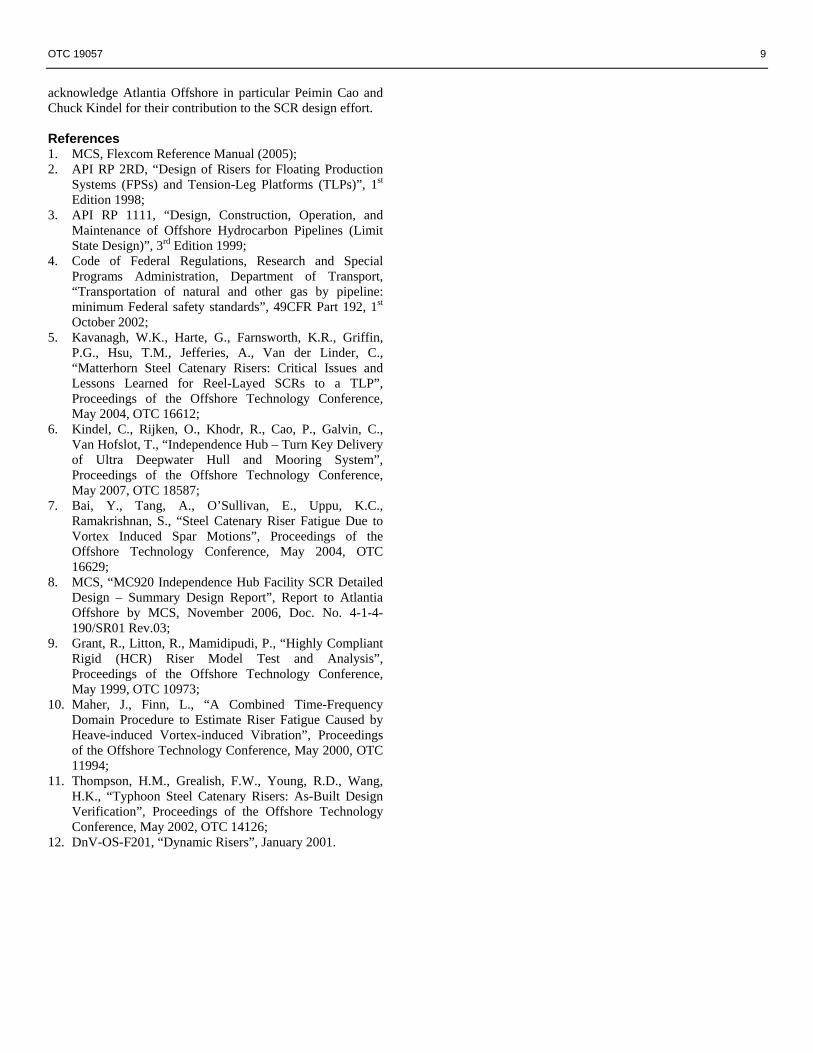
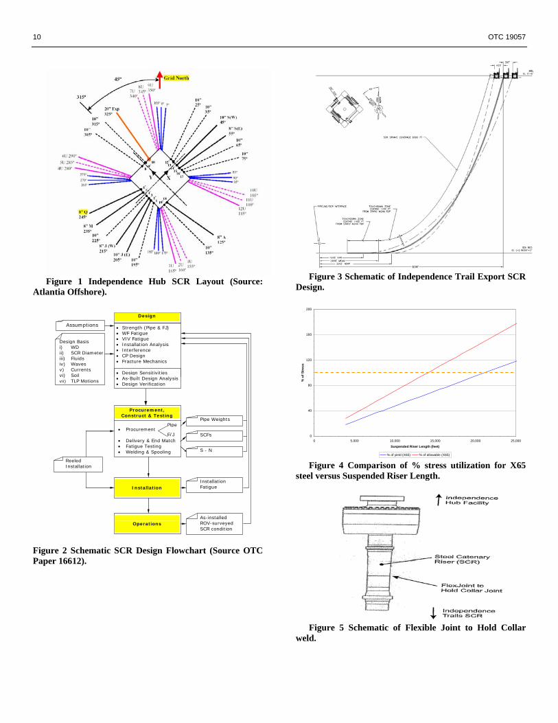
from the platform via a 20-inch diameter Steel Catenary Riser (SCR) that transitions into the 24-inch diameter Independence Trail Pipeline which runs northwest for 134 miles, terminating at a fixed platform in 115 ft of water in Block 68 of West Delta area. The 20-inch Independence Trail SCR and 24-inch Independence Trail Pipeline are 100% owned and operated by Enterprise Product Partners LP, while Enterprise owns 80% of the DeepDraft Semi™. Figure 1 presents the DeepDraft Semi™ , SCR and subsea layout. Design and Construction of Gas Export SCR The design and construction of the export riser for Independence Hub required that multiple parties work and interface in order to execute the project of designing the world’s deepest export system. With many disciplines interfacing, an Integrated Project Team (IPT) was formed to ensure the timely flow of information and ultimate safe, robust project design and delivery. Figure 2 presents a typical flowchart of the SCR design and construction process per Kavanagh et al. [5], highlighting the key activities and interfaces for the project:
• Design • Procurement • Weld qualification and testing • Construction • Installation • Operation
Figure 2 also illustrates the cycles and iterations that may be required and undertaken during project execution to achieve a feasible riser system design.
Prior to concluding FEED, GulfTerra Energy Partners LP (acquired by Enterprise 2004), all stakeholders and IPT members drafted a Riser Design Basis and Methodology document detailing the minimum requirements of the flowline risers and export riser system and their expectation of how detailed design of the risers was to be executed. This document formed part of the functional specification for the competing EPC contractors, thus providing Enterprise significant influence over design execution for the export SCR. Chief among the requirements were; SCR design criteria, functional requirements, design load cases and design methodology.
The Riser Design Basis and Methodology document was a live document and periodically updated to reflect availability of more accurate project data, while also acting as the change control within the SCR design scope of the project. As the execution phase export SCR design progressed the Riser
OTC 19057
Independence Trail—Steel Catenary Riser Design and Materials Conor Galvin, MCS, and Rick Hill, EWI Microalloying

2 OTC 19057
Design Basis and Methodology document became comprehensively populated with most of the required design inputs, i.e. SCR azimuth bearing, porch location on hull, flexible joint characteristics, metocean conditions, fluid particulars of export gas, DeepDraft Semi™ global motion performance data, etc. Gas Export Global Configuration The 20-inch gas export SCR departs the Independence Hub DeepDraft Semi™ using a riser porch and flexible joint arrangement. Table 1 presents the key characteristics of the as designed gas export SCR, and Figure 3 presents a schematic of the SCR configuration.
Table 1 Gas Export Key Design Characteristics Parameter Value Steel Pipe Grade X65 Outer Diameter (inch) 20.00 Wall Thickness (inch) 1.21 Hang-off Angle (deg) 15.00 Azimuth Angle (deg) N 325o E Strake Length (ft) 8,300 Horizontal Distance to TDP (ft) 5,527 Suspended Catenary Length (ft) 10,340 Water Depth at TDP (ft) 7,840
Typical of large diameter risers in ultra deepwater applications, the SCR wall size (1.21-inch) was governed by the collapse resistance of the pipe on the seabed. The riser joints were fabricated as longitudinal double submerged arc welded line pipe. Supplemental specifications were used to ensure consistent mechanical and dimensional properties with particular focus on the chemical composition, uniform elongation (strain capacity), inherent toughness and pipe end tolerances, to facilitate field and shop welding. Ultra Deepwater SCRs One interesting trend to note as the industry moves to deeper water is the rate of utilization of allowable stress for deepwater SCRs. For a flooded X65 SCR, Figure 4 presents a graph of the percentage of a steel pipe yield strength utilized by the tensile load alone versus riser catenary (suspended) length. At approximately 14,000 ft of suspended riser length 67% of the yield strength of the top X65 riser joints is realized due to hanging riser weight alone, while the top riser joints would reach yield (65 ksi) at 22,000 ft of suspended length. The relevance of this is clear, when one considers that the Independence Trail Gas Export SCR has a suspended length in excess of 10,300 ft, water filled, the top joints experience almost 32 ksi from tensile load alone. Maximum allowable stress during normal operation is 67% of riser yield strength, i.e. 43 ksi. Therefore, the top joints are almost at their respective design limits before the stress components from hoop and bending are even included. SCR Global Design The global design of the gas export SCR required a comprehensive suite of design tasks to demonstrate a robust and safe system design. Part of this design approach meant capturing updated and new revisions of project data with each cycle of riser design.
In general the key design tasks can be summarized as follows: 1. VIV Fatigue Design 2. Wave-induced Fatigue Design 3. VIM Fatigue Design 4. HVIV Fatigue Design 5. Interference Design 6. Strength Design 7. Cathodic Protection Design 8. Sensitivities
Each of these design activities for the gas export SCR are discussed in detail in the following subsections of the paper.
Design Basis and Assumptions
The design of the Independence Trail Export SCR was based on certain design assumptions made at the start of the execution phase. Chief among these were the following:
Assumptions on Delivered Pipe Weight. The design of an SCR must reflect the specifications used for the SCR pipe procurement; specifically steel grade, wall thickness tolerances and ovality. The SCR designer will very likely target a nominal SCR pipe wall thickness based on a wall sizing exercise; assessing pipe burst and collapse requirements of the riser. The SCR design analysis must be aligned with the SCR pipe mean weight and wall thickness as a result of the manufacturing tolerances, rather than the nominal weight and wall thickness. The pipe specification required delivered joints with a wall thickness tolerance of -8% to +20%. This tolerance of wall size results in a mean wall thickness of +6% above nominal. SCR pipe procurement experiences from previous projects were that the pipe mills invariably deliver their pipe on the positive side of the specification mean, in an attempt to minimize the rejection rate of their product by falling below the lower tolerance limit. Therefore, for the Independence Trail SCR, the SCR design was completed for SCR pipe that was assumed +8% heavier that nominal weight.
In addition to this assumption on pipe wall tolerance, design sensitivity to nominal and +12% on nominal dry weight were performed as part of the fatigue and strength design of the Independence Trail SCR.
Assumptions on Girth Weld Target S-N Curve and Stress Concentration Factor. To perform the fatigue design of the export SCR initial assumptions in regard to pipe girth weld performance were required in lieu of the project specific weld procedure qualification and fatigue testing results. From previous project experience of large diameter seam welded riser pipe, the E S-N Curve and an SCF of 1.2 were targeted for SCR design. For the welds to achieve these performance characteristics, end matching and pipe sorting would be required to minimize Hi Lo, but importantly OD or ID grinding of the welds was not required for this assumption.
Assumption on SCR Hang-off Angle. On the completion of the FEED study of the SCR, a hang-off angle of 12o from vertical was targeted as the final design angle. This design assumption was required to be validated through the detailed strength and fatigue analysis of the riser system performance.
Assumption on SCR Azimuth Angle. The Independence Trail pipeline corridor was confirmed at the start of the project execution phase. However, the SCR azimuth angle of N 325o E needed to align with the pipeline would have to be validated
OTC 19057 3
through the comprehensive suite of design analysis to be undertaken on the SCR system.
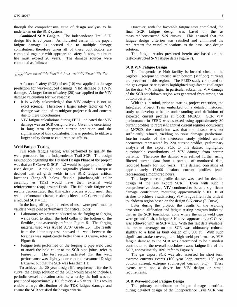
Combined SCR Fatigue. The Independence Trail SCR design life is 20 years. As indicated earlier in the paper, fatigue damage is accrued due to multiple damage contributors, therefore when all of these contributors are combined together with appropriate safety factors, minimum life must exceed 20 years. The damage sources were combined as follows:
insDFOSHVIVDFOSVIVLTDFOSVIMDFOSinducedwaveD
years+×+×+×+×−≥ 12_1120
1
A factor of safety (FOS) of ten (10) was applied to damage
prediction for wave-induced damage, VIM damage & HVIV damage. A larger factor of safety (20) was applied to the VIV damage calculation for two reasons: • It is widely acknowledged that VIV analysis is not an
exact science. Therefore a larger safety factor on VIV damage was applied to mitigate project risk and concern due to these uncertainties;
• VIV fatigue calculations during FEED indicated that VIV damage was an SCR design driver. Given the uncertainty in long term deepwater current prediction and the significance of this contributor, it was prudent to utilize a larger safety factor to capture these affects.
Weld Fatigue Testing
Full scale fatigue testing was performed to qualify the weld procedure for the Independence Trail SCR. The design assumption beginning the Detailed Design Phase of the project was that an E Curve & SCF =1.2 would be appropriate for the riser design. Although not originally planned, Enterprise decided that all girth welds in the SCR fatigue critical locations (hang-off below flexible joint/hang-off collar assembly & TDZ) would have their external weld reinforcement (cap) ground flush. The full scale fatigue test results demonstrated that this extra process would mean that weld performance characteristics achieved a C Curve and also a reduced SCF = 1.1.
In the hang-off region, a series of tests were performed to validate weld joint performance for critical joints: • Laboratory tests were conducted on the forging to forging
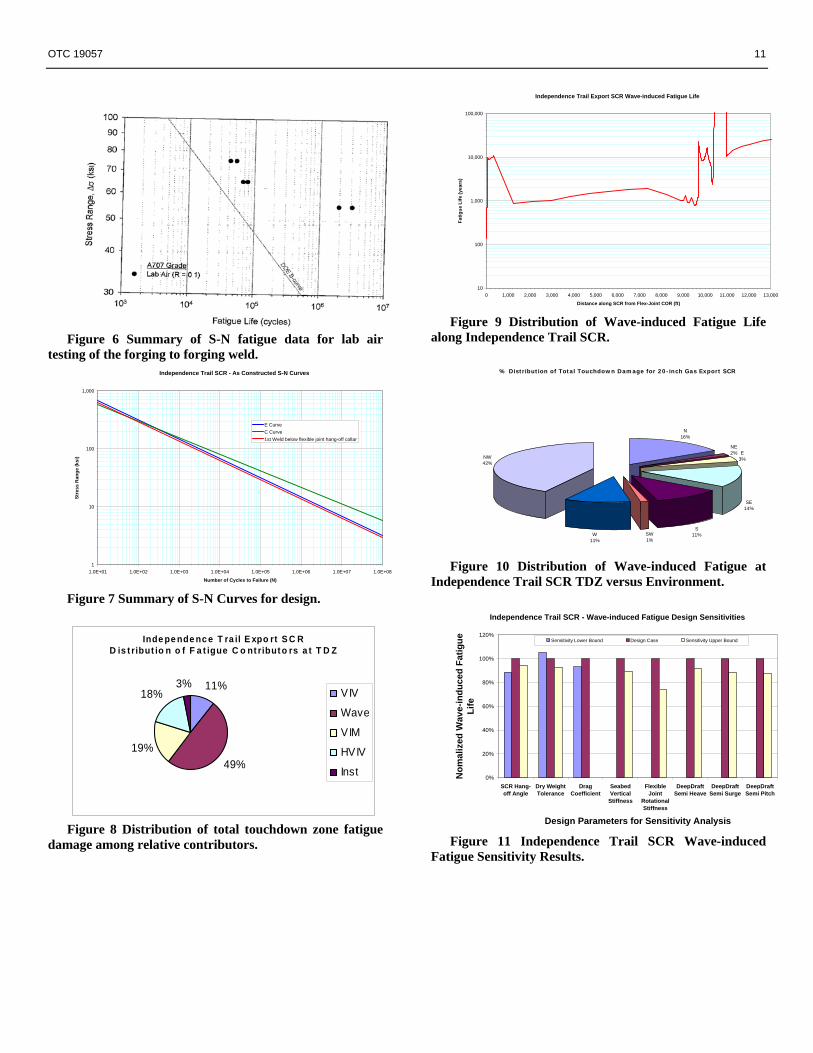
welds used to attach the hold collar to the bottom of the flexible joint assembly, refer to Figure 5. The forging material used was ASTM A707 Grade L5. The results from the laboratory tests showed the weld between the forgings was significantly better than a B Curve, refer to Figure 6;
• Fatigue tests performed on the forging to pipe weld used to attach the hold collar to the SCR pipe joints, refer to Figure 5. The test results indicated that this weld performance was slightly poorer than the assumed Design E Curve, but that the SCF was less than 1.1.
To achieve the 20 year design life requirement for the E curve, the design solution of the SCR would have to include a periodic vessel relocation scheme, whereby the hull was re-positioned approximately 100 ft every 4 – 5 years. This would enable a large distribution of the TDZ fatigue damage and ensure the SCR satisfied the design criteria.
However, with the favorable fatigue tests completed, the final SCR fatigue design was based on the as measured/constructed S-N curves. This ensured that the fatigue design criterion was satisfied and eliminated the requirement for vessel relocations as the base case design solution.
The fatigue results presented herein are based on the test/constructed S-N fatigue data (Figure 7). SCR VIV Fatigue Design
The Independence Hub facility is located close to the Sigsbee Escarpment, intense near bottom (seafloor) currents are prevalent in this region. The FEED study completed on the gas export riser system highlighted significant challenges for the riser VIV design. In particular substantial VIV damage of the SCR touchdown region was generated from strong near bottom currents.
With this in mind, prior to starting project execution, the Integrated Project Team embarked on a detailed metocean study to develop a better understanding and definition of expected current profiles at block MC920. SCR VIV performance in FEED was assessed using approximately 30 current profiles to represent annual current regimes occurrence at MC920, the conclusion was that the dataset was not sufficiently refined, yielding spurious damage predictions. Interim results of the metocean study yielded annual occurrence represented by 220 current profiles, preliminary analysis of the export SCR to this dataset highlighted questionable contributions of VIV damage from certain currents. Therefore the dataset was refined further using filtered current data from a sample of monitored data, recorded hourly for two years. This dataset, consisting of approximately 17,000 distinct current profiles (each representing a monitored hour).
This large current profile dataset was used for detailed design of the gas export SCR. Even with such a comprehensive dataset, VIV continued to be as a significant damage contributor, requiring approximately 9,100 ft of strakes to achieve a satisfactory VIV fatigue life in the critical touchdown region based on the design S-N curve (E Curve).
Later during the project, the results of the welding procedure qualification and fatigue testing program indicated that in the SCR touchdown zone where the girth weld caps were ground flush, a fatigue S-N curve approaching a C Curve was achieved with an SCF = 1.1. With this test data available, the strake coverage on the SCR was ultimately reduced slightly to a final as built design of 8,300 ft. With such significant strake coverage and high weld performance, VIV fatigue damage to the SCR was determined to be a modest contributor to the overall touchdown zone fatigue life of the SCR, approximately 10%; refer to Figure 8.
The gas export SCR was also assessed for short term extreme currents events (100 year loop current, 100 year bottom current, extreme submerged current, etc.). These events were not a driver for VIV design or strake requirements.
SCR Wave-induced Fatigue Design
The primary contributor to fatigue damage identified during detailed design of the Independence Trail SCR was
4 OTC 19057
wave-induced fatigue. This contributor is primarily driven by the wind & wave-induced motion characteristics of the DeepDraft Semi™.
The dynamic touchdown zone of the SCR was predicted to be almost 2,500 ft in length, based on the maximum predicted DeepDraft Semi™ excursions. With such a large region of SCR pipe susceptible to intermittent seabed touchdown, the project team felt it prudent to perform all SCR wave-induced fatigue analysis using a time domain approach, thus capturing all SCR non-linearities, i.e. seabed interaction, drag loading, non-linear flexible joint rotational stiffness characteristics, etc.
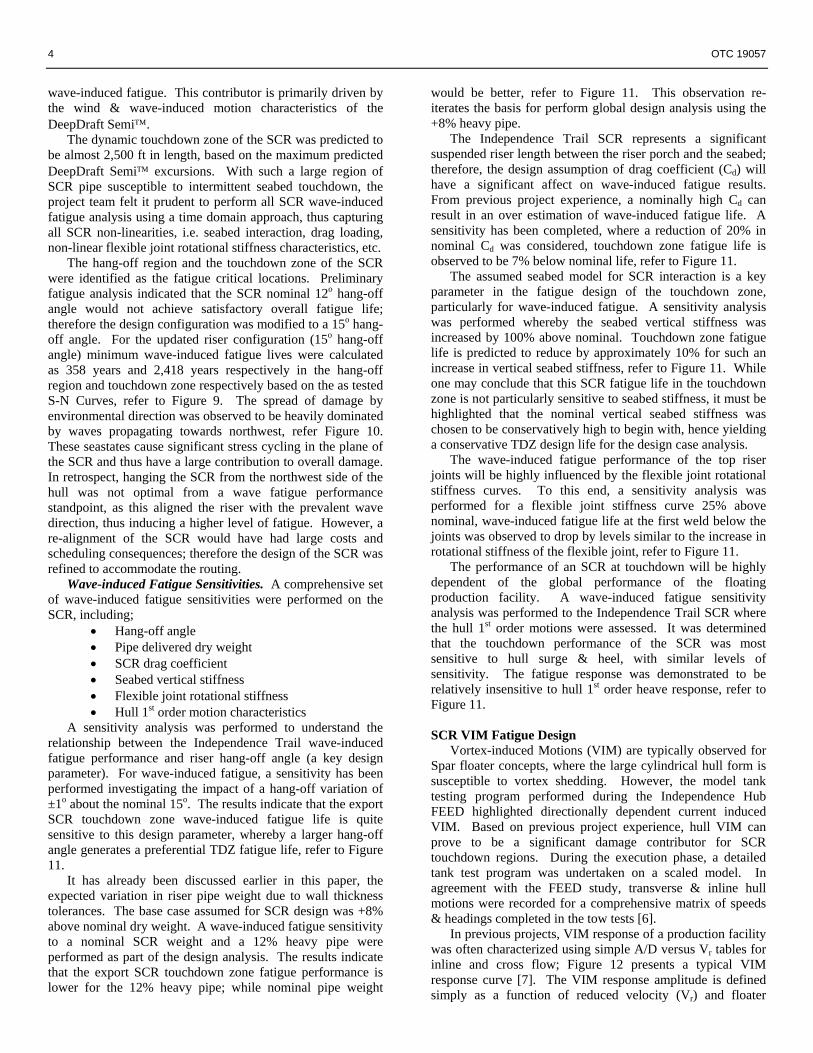
The hang-off region and the touchdown zone of the SCR were identified as the fatigue critical locations. Preliminary fatigue analysis indicated that the SCR nominal 12o hang-off angle would not achieve satisfactory overall fatigue life; therefore the design configuration was modified to a 15o hang-off angle. For the updated riser configuration (15o hang-off angle) minimum wave-induced fatigue lives were calculated as 358 years and 2,418 years respectively in the hang-off region and touchdown zone respectively based on the as tested S-N Curves, refer to Figure 9. The spread of damage by environmental direction was observed to be heavily dominated by waves propagating towards northwest, refer Figure 10. These seastates cause significant stress cycling in the plane of the SCR and thus have a large contribution to overall damage. In retrospect, hanging the SCR from the northwest side of the hull was not optimal from a wave fatigue performance standpoint, as this aligned the riser with the prevalent wave direction, thus inducing a higher level of fatigue. However, a re-alignment of the SCR would have had large costs and scheduling consequences; therefore the design of the SCR was refined to accommodate the routing.
Wave-induced Fatigue Sensitivities. A comprehensive set of wave-induced fatigue sensitivities were performed on the SCR, including;
• Hang-off angle • Pipe delivered dry weight • SCR drag coefficient • Seabed vertical stiffness • Flexible joint rotational stiffness • Hull 1st order motion characteristics
A sensitivity analysis was performed to understand the relationship between the Independence Trail wave-induced fatigue performance and riser hang-off angle (a key design parameter). For wave-induced fatigue, a sensitivity has been performed investigating the impact of a hang-off variation of ±1o about the nominal 15o. The results indicate that the export SCR touchdown zone wave-induced fatigue life is quite sensitive to this design parameter, whereby a larger hang-off angle generates a preferential TDZ fatigue life, refer to Figure 11.
It has already been discussed earlier in this paper, the expected variation in riser pipe weight due to wall thickness tolerances. The base case assumed for SCR design was +8% above nominal dry weight. A wave-induced fatigue sensitivity to a nominal SCR weight and a 12% heavy pipe were performed as part of the design analysis. The results indicate that the export SCR touchdown zone fatigue performance is lower for the 12% heavy pipe; while nominal pipe weight
would be better, refer to Figure 11. This observation re-iterates the basis for perform global design analysis using the +8% heavy pipe.
The Independence Trail SCR represents a significant suspended riser length between the riser porch and the seabed; therefore, the design assumption of drag coefficient (Cd) will have a significant affect on wave-induced fatigue results. From previous project experience, a nominally high Cd can result in an over estimation of wave-induced fatigue life. A sensitivity has been completed, where a reduction of 20% in nominal Cd was considered, touchdown zone fatigue life is observed to be 7% below nominal life, refer to Figure 11.
The assumed seabed model for SCR interaction is a key parameter in the fatigue design of the touchdown zone, particularly for wave-induced fatigue. A sensitivity analysis was performed whereby the seabed vertical stiffness was increased by 100% above nominal. Touchdown zone fatigue life is predicted to reduce by approximately 10% for such an increase in vertical seabed stiffness, refer to Figure 11. While one may conclude that this SCR fatigue life in the touchdown zone is not particularly sensitive to seabed stiffness, it must be highlighted that the nominal vertical seabed stiffness was chosen to be conservatively high to begin with, hence yielding a conservative TDZ design life for the design case analysis.
The wave-induced fatigue performance of the top riser joints will be highly influenced by the flexible joint rotational stiffness curves. To this end, a sensitivity analysis was performed for a flexible joint stiffness curve 25% above nominal, wave-induced fatigue life at the first weld below the joints was observed to drop by levels similar to the increase in rotational stiffness of the flexible joint, refer to Figure 11.
The performance of an SCR at touchdown will be highly dependent of the global performance of the floating production facility. A wave-induced fatigue sensitivity analysis was performed to the Independence Trail SCR where the hull 1st order motions were assessed. It was determined that the touchdown performance of the SCR was most sensitive to hull surge & heel, with similar levels of sensitivity. The fatigue response was demonstrated to be relatively insensitive to hull 1st order heave response, refer to Figure 11.
SCR VIM Fatigue Design
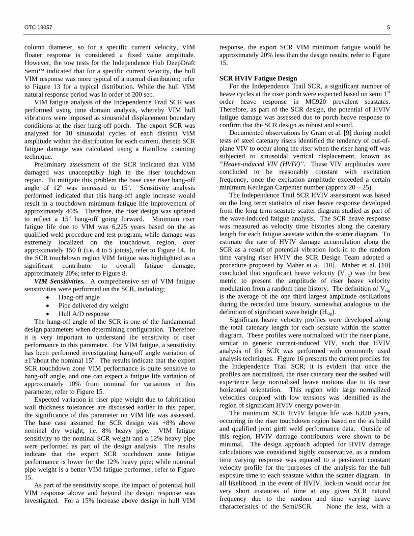
Vortex-induced Motions (VIM) are typically observed for Spar floater concepts, where the large cylindrical hull form is susceptible to vortex shedding. However, the model tank testing program performed during the Independence Hub FEED highlighted directionally dependent current induced VIM. Based on previous project experience, hull VIM can prove to be a significant damage contributor for SCR touchdown regions. During the execution phase, a detailed tank test program was undertaken on a scaled model. In agreement with the FEED study, transverse & inline hull motions were recorded for a comprehensive matrix of speeds & headings completed in the tow tests [6].
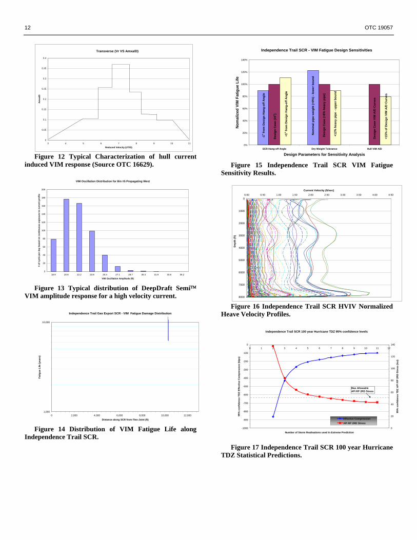
In previous projects, VIM response of a production facility was often characterized using simple A/D versus Vr tables for inline and cross flow; Figure 12 presents a typical VIM response curve [7]. The VIM response amplitude is defined simply as a function of reduced velocity (Vr) and floater
OTC 19057 5
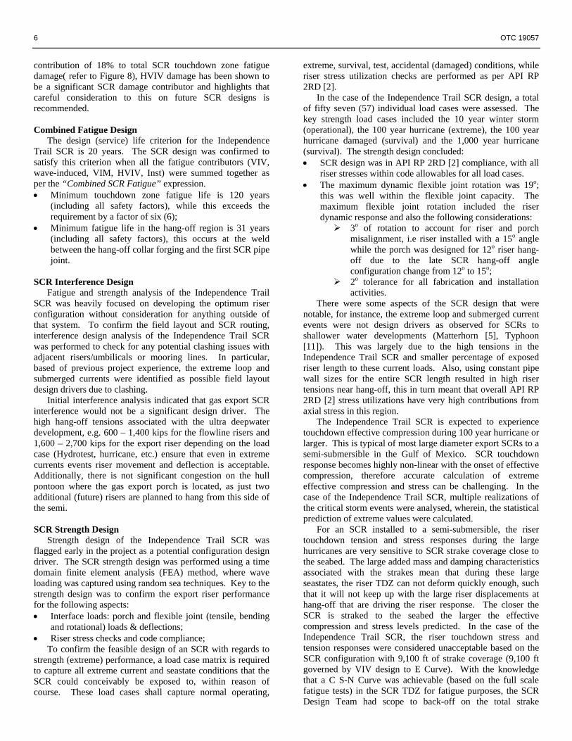
column diameter, so for a specific current velocity, VIM floater response is considered a fixed value amplitude. However, the tow tests for the Independence Hub DeepDraft Semi™ indicated that for a specific current velocity, the hull VIM response was more typical of a normal distribution; refer to Figure 13 for a typical distribution. While the hull VIM natural response period was in order of 200 sec.
VIM fatigue analysis of the Independence Trail SCR was performed using time domain analysis, whereby VIM hull vibrations were imposed as sinusoidal displacement boundary conditions at the riser hang-off porch. The export SCR was analyzed for 10 sinusoidal cycles of each distinct VIM amplitude within the distribution for each current, therein SCR fatigue damage was calculated using a Rainflow counting technique.
Preliminary assessment of the SCR indicated that VIM damaged was unacceptably high in the riser touchdown region. To mitigate this problem the base case riser hang-off angle of 12o was increased to 15o. Sensitivity analysis performed indicated that this hang-off angle increase would result in a touchdown minimum fatigue life improvement of approximately 40%. Therefore, the riser design was updated to reflect a 15o hang-off going forward. Minimum riser fatigue life due to VIM was 6,225 years based on the as qualified weld procedure and test program, while damage was extremely localized on the touchdown region, over approximately 150 ft (i.e. 4 to 5 joints), refer to Figure 14. In the SCR touchdown region VIM fatigue was highlighted as a significant contributor to overall fatigue damage, approximately 20%; refer to Figure 8.
VIM Sensitivities. A comprehensive set of VIM fatigue sensitivities were performed on the SCR, including;
• Hang-off angle • Pipe delivered dry weight • Hull A/D response
The hang-off angle of the SCR is one of the fundamental design parameters when determining configuration. Therefore it is very important to understand the sensitivity of riser performance to this parameter. For VIM fatigue, a sensitivity has been performed investigating hang-off angle variation of ±1oabout the nominal 15o. The results indicate that the export SCR touchdown zone VIM performance is quite sensitive to hang-off angle, and one can expect a fatigue life variation of approximately 10% from nominal for variations in this parameter, refer to Figure 15.
Expected variation in riser pipe weight due to fabrication wall thickness tolerances are discussed earlier in this paper, the significance of this parameter on VIM life was assessed. The base case assumed for SCR design was +8% above nominal dry weight, i.e. 8% heavy pipe. VIM fatigue sensitivity to the nominal SCR weight and a 12% heavy pipe were performed as part of the design analysis. The results indicate that the export SCR touchdown zone fatigue performance is lower for the 12% heavy pipe; while nominal pipe weight is a better VIM fatigue performer, refer to Figure 15.
As part of the sensitivity scope, the impact of potential hull VIM response above and beyond the design response was investigated. For a 15% increase above design in hull VIM
response, the export SCR VIM minimum fatigue would be approximately 20% less than the design results, refer to Figure 15.
SCR HVIV Fatigue Design
For the Independence Trail SCR, a significant number of heave cycles at the riser porch were expected based on semi 1st order heave response in MC920 prevalent seastates. Therefore, as part of the SCR design, the potential of HVIV fatigue damage was assessed due to porch heave response to confirm that the SCR design as robust and sound.
Documented observations by Grant et al. [9] during model tests of steel catenary risers identified the tendency of out-of-plane VIV to occur along the riser when the riser hang-off was subjected to sinusoidal vertical displacement, known as “Heave-induced VIV (HVIV)”. These VIV amplitudes were concluded to be reasonably constant with excitation frequency, once the excitation amplitude exceeded a certain minimum Keulegan Carpenter number (approx 20 – 25).
The Independence Trail SCR HVIV assessment was based on the long term statistics of riser heave response developed from the long term seastate scatter diagram studied as part of the wave-induced fatigue analysis. The SCR heave response was measured as velocity time histories along the catenary length for each fatigue seastate within the scatter diagram. To estimate the rate of HVIV damage accumulation along the SCR as a result of potential vibration lock-in to the random time varying riser HVIV the SCR Design Team adopted a procedure proposed by Maher et al. [10]. Maher et al. [10] concluded that significant heave velocity (Vsig) was the best metric to present the amplitude of riser heave velocity modulation from a random time history. The definition of Vsig is the average of the one third largest amplitude oscillations during the recorded time history, somewhat analogous to the definition of significant wave height (Hsig).
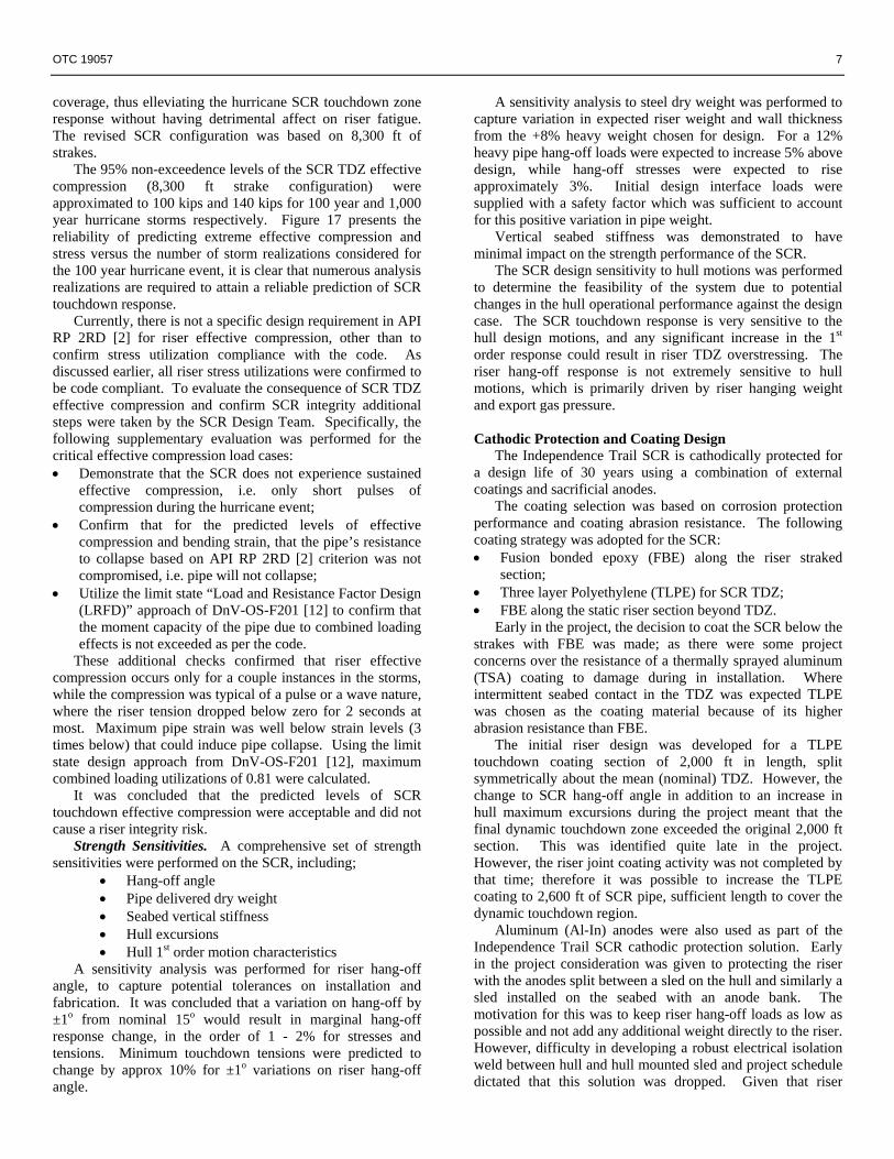
Significant heave velocity profiles were developed along the total catenary length for each seastate within the scatter diagram. These profiles were normalized with the riser plane, similar to generic current-induced VIV, such that HVIV analysis of the SCR was performed with commonly used analysis techniques. Figure 16 presents the current profiles for the Independence Trail SCR; it is evident that once the profiles are normalized, the riser catenary near the seabed will experience large normalized heave motions due to its near horizontal orientation. This region with large normalized velocities coupled with low tensions was identified as the region of significant HVIV energy power-in.
The minimum SCR HVIV fatigue life was 6,820 years, occurring in the riser touchdown region based on the as build and qualified joint girth weld performance data. Outside of this region, HVIV damage contributors were shown to be minimal. The design approach adopted for HVIV damage calculations was considered highly conservative, as a random time varying response was equated to a persistent constant velocity profile for the purposes of the analysis for the full exposure time to each seastate within the scatter diagram. In all likelihood, in the event of HVIV, lock-in would occur for very short instances of time at any given SCR natural frequency due to the random and time varying heave characteristics of the Semi/SCR. None the less, with a
6 OTC 19057
contribution of 18% to total SCR touchdown zone fatigue damage( refer to Figure 8), HVIV damage has been shown to be a significant SCR damage contributor and highlights that careful consideration to this on future SCR designs is recommended.
Combined Fatigue Design
The design (service) life criterion for the Independence Trail SCR is 20 years. The SCR design was confirmed to satisfy this criterion when all the fatigue contributors (VIV, wave-induced, VIM, HVIV, Inst) were summed together as per the “Combined SCR Fatigue” expression. • Minimum touchdown zone fatigue life is 120 years
(including all safety factors), while this exceeds the requirement by a factor of six (6);
• Minimum fatigue life in the hang-off region is 31 years (including all safety factors), this occurs at the weld between the hang-off collar forging and the first SCR pipe joint.
SCR Interference Design
Fatigue and strength analysis of the Independence Trail SCR was heavily focused on developing the optimum riser configuration without consideration for anything outside of that system. To confirm the field layout and SCR routing, interference design analysis of the Independence Trail SCR was performed to check for any potential clashing issues with adjacent risers/umbilicals or mooring lines. In particular, based of previous project experience, the extreme loop and submerged currents were identified as possible field layout design drivers due to clashing.
Initial interference analysis indicated that gas export SCR interference would not be a significant design driver. The high hang-off tensions associated with the ultra deepwater development, e.g. 600 – 1,400 kips for the flowline risers and 1,600 – 2,700 kips for the export riser depending on the load case (Hydrotest, hurricane, etc.) ensure that even in extreme currents events riser movement and deflection is acceptable. Additionally, there is not significant congestion on the hull pontoon where the gas export porch is located, as just two additional (future) risers are planned to hang from this side of the semi.
SCR Strength Design
Strength design of the Independence Trail SCR was flagged early in the project as a potential configuration design driver. The SCR strength design was performed using a time domain finite element analysis (FEA) method, where wave loading was captured using random sea techniques. Key to the strength design was to confirm the export riser performance for the following aspects: • Interface loads: porch and flexible joint (tensile, bending
and rotational) loads & deflections; • Riser stress checks and code compliance;
To confirm the feasible design of an SCR with regards to strength (extreme) performance, a load case matrix is required to capture all extreme current and seastate conditions that the SCR could conceivably be exposed to, within reason of course. These load cases shall capture normal operating,
extreme, survival, test, accidental (damaged) conditions, while riser stress utilization checks are performed as per API RP 2RD [2].
In the case of the Independence Trail SCR design, a total of fifty seven (57) individual load cases were assessed. The key strength load cases included the 10 year winter storm (operational), the 100 year hurricane (extreme), the 100 year hurricane damaged (survival) and the 1,000 year hurricane (survival). The strength design concluded: • SCR design was in API RP 2RD [2] compliance, with all
riser stresses within code allowables for all load cases. • The maximum dynamic flexible joint rotation was 19o;
this was well within the flexible joint capacity. The maximum flexible joint rotation included the riser dynamic response and also the following considerations:
3o of rotation to account for riser and porch misalignment, i.e riser installed with a 15o angle while the porch was designed for 12o riser hang-off due to the late SCR hang-off angle configuration change from 12o to 15o;
2o tolerance for all fabrication and installation activities.
There were some aspects of the SCR design that were notable, for instance, the extreme loop and submerged current events were not design drivers as observed for SCRs to shallower water developments (Matterhorn [5], Typhoon [11]). This was largely due to the high tensions in the Independence Trail SCR and smaller percentage of exposed riser length to these current loads. Also, using constant pipe wall sizes for the entire SCR length resulted in high riser tensions near hang-off, this in turn meant that overall API RP 2RD [2] stress utilizations have very high contributions from axial stress in this region.
The Independence Trail SCR is expected to experience touchdown effective compression during 100 year hurricane or larger. This is typical of most large diameter export SCRs to a semi-submersible in the Gulf of Mexico. SCR touchdown response becomes highly non-linear with the onset of effective compression, therefore accurate calculation of extreme effective compression and stress can be challenging. In the case of the Independence Trail SCR, multiple realizations of the critical storm events were analysed, wherein, the statistical prediction of extreme values were calculated.
For an SCR installed to a semi-submersible, the riser touchdown tension and stress responses during the large hurricanes are very sensitive to SCR strake coverage close to the seabed. The large added mass and damping characteristics associated with the strakes mean that during these large seastates, the riser TDZ can not deform quickly enough, such that it will not keep up with the large riser displacements at hang-off that are driving the riser response. The closer the SCR is straked to the seabed the larger the effective compression and stress levels predicted. In the case of the Independence Trail SCR, the riser touchdown stress and tension responses were considered unacceptable based on the SCR configuration with 9,100 ft of strake coverage (9,100 ft governed by VIV design to E Curve). With the knowledge that a C S-N Curve was achievable (based on the full scale fatigue tests) in the SCR TDZ for fatigue purposes, the SCR Design Team had scope to back-off on the total strake
OTC 19057 7
coverage, thus elleviating the hurricane SCR touchdown zone response without having detrimental affect on riser fatigue. The revised SCR configuration was based on 8,300 ft of strakes.
The 95% non-exceedence levels of the SCR TDZ effective compression (8,300 ft strake configuration) were approximated to 100 kips and 140 kips for 100 year and 1,000 year hurricane storms respectively. Figure 17 presents the reliability of predicting extreme effective compression and stress versus the number of storm realizations considered for the 100 year hurricane event, it is clear that numerous analysis realizations are required to attain a reliable prediction of SCR touchdown response.
Currently, there is not a specific design requirement in API RP 2RD [2] for riser effective compression, other than to confirm stress utilization compliance with the code. As discussed earlier, all riser stress utilizations were confirmed to be code compliant. To evaluate the consequence of SCR TDZ effective compression and confirm SCR integrity additional steps were taken by the SCR Design Team. Specifically, the following supplementary evaluation was performed for the critical effective compression load cases: • Demonstrate that the SCR does not experience sustained
effective compression, i.e. only short pulses of compression during the hurricane event;
• Confirm that for the predicted levels of effective compression and bending strain, that the pipe’s resistance to collapse based on API RP 2RD [2] criterion was not compromised, i.e. pipe will not collapse;
• Utilize the limit state “Load and Resistance Factor Design (LRFD)” approach of DnV-OS-F201 [12] to confirm that the moment capacity of the pipe due to combined loading effects is not exceeded as per the code.
These additional checks confirmed that riser effective compression occurs only for a couple instances in the storms, while the compression was typical of a pulse or a wave nature, where the riser tension dropped below zero for 2 seconds at most. Maximum pipe strain was well below strain levels (3 times below) that could induce pipe collapse. Using the limit state design approach from DnV-OS-F201 [12], maximum combined loading utilizations of 0.81 were calculated.
It was concluded that the predicted levels of SCR touchdown effective compression were acceptable and did not cause a riser integrity risk.
Strength Sensitivities. A comprehensive set of strength sensitivities were performed on the SCR, including;
• Hang-off angle • Pipe delivered dry weight • Seabed vertical stiffness • Hull excursions • Hull 1st order motion characteristics
A sensitivity analysis was performed for riser hang-off angle, to capture potential tolerances on installation and fabrication. It was concluded that a variation on hang-off by ±1o from nominal 15o would result in marginal hang-off response change, in the order of 1 - 2% for stresses and tensions. Minimum touchdown tensions were predicted to change by approx 10% for ±1o variations on riser hang-off angle.
A sensitivity analysis to steel dry weight was performed to capture variation in expected riser weight and wall thickness from the +8% heavy weight chosen for design. For a 12% heavy pipe hang-off loads were expected to increase 5% above design, while hang-off stresses were expected to rise approximately 3%. Initial design interface loads were supplied with a safety factor which was sufficient to account for this positive variation in pipe weight.
Vertical seabed stiffness was demonstrated to have minimal impact on the strength performance of the SCR.
The SCR design sensitivity to hull motions was performed to determine the feasibility of the system due to potential changes in the hull operational performance against the design case. The SCR touchdown response is very sensitive to the hull design motions, and any significant increase in the 1st order response could result in riser TDZ overstressing. The riser hang-off response is not extremely sensitive to hull motions, which is primarily driven by riser hanging weight and export gas pressure.
Cathodic Protection and Coating Design
The Independence Trail SCR is cathodically protected for a design life of 30 years using a combination of external coatings and sacrificial anodes.
The coating selection was based on corrosion protection performance and coating abrasion resistance. The following coating strategy was adopted for the SCR: • Fusion bonded epoxy (FBE) along the riser straked
section; • Three layer Polyethylene (TLPE) for SCR TDZ; • FBE along the static riser section beyond TDZ.
Early in the project, the decision to coat the SCR below the strakes with FBE was made; as there were some project concerns over the resistance of a thermally sprayed aluminum (TSA) coating to damage during in installation. Where intermittent seabed contact in the TDZ was expected TLPE was chosen as the coating material because of its higher abrasion resistance than FBE.
The initial riser design was developed for a TLPE touchdown coating section of 2,000 ft in length, split symmetrically about the mean (nominal) TDZ. However, the change to SCR hang-off angle in addition to an increase in hull maximum excursions during the project meant that the final dynamic touchdown zone exceeded the original 2,000 ft section. This was identified quite late in the project. However, the riser joint coating activity was not completed by that time; therefore it was possible to increase the TLPE coating to 2,600 ft of SCR pipe, sufficient length to cover the dynamic touchdown region.
Aluminum (Al-In) anodes were also used as part of the Independence Trail SCR cathodic protection solution. Early in the project consideration was given to protecting the riser with the anodes split between a sled on the hull and similarly a sled installed on the seabed with an anode bank. The motivation for this was to keep riser hang-off loads as low as possible and not add any additional weight directly to the riser. However, difficulty in developing a robust electrical isolation weld between hull and hull mounted sled and project schedule dictated that this solution was dropped. Given that riser

8 OTC 19057
protection for one end was not option, bracelet anodes directly mounted to the riser would be required for protect of the top SCR section. This meant progressing with a seabed anode sled was no longer the design case; therefore the idea of the seabed sled was also dropped. One concern with bracelet anodes was that the welds needed to attach the copper jumper leads to the SCR surface may create hard spots on the riser. To mitigate this risk, anodes were not attached to regions of high fatigue rate or high stress on the SCR (TDZ and hang-off), but instead the required anodes were concentrated just outside the critical zone to provide the required CP protection and in the mid catenary section.
SCR Global Design Verification As part of the design process, independent verification was performed on the strength and fatigue design analysis of the export SCR. The verification scope was almost as detailed as the full design scope, given the record water depth of the Independence Trail project, with the verification agent performing a full suite of independent analysis.
The independent strength and fatigue analysis indicated that the design results agreed very well with the verification results, whilst the conclusion that the export SCR system was a robust design. Conclusions The Independence Trail SCR is the deepest large diameter SCR to be installed anywhere in the world to date. Significant lessons learned have been identified with application to future deepwater SCR projects: • Developing a Riser Design Basis & Methodology
document for Detailed Design as part of the FEED deliverables. This report should be developed and maintained by the operator. Getting this document circulated and buy-in from all stakeholders prior to completing FEED ensures that the minimum requirements from SCR design are agreed prior to contract award. This provides the operator with significant influence on the design execution of the SCR system;
• The Independence Trail SCR may very well be the deepest large diameter SCR installed in the world; however, the trend towards ultra deepwater developments is becoming more common. The high stress utilization associated with these ultra deepwater SCRs from tensile load alone is striking. For future ultra deepwater SCRs, configurations with multiple wall sizes, higher grade steels or buoyant waves may be likely design solutions in an effort to control riser tension near hang-off such that these pipe joints are not overstressed;
• SCR Design Basis assumptions are required to be validated during the project design and construction stages. In the case of the Independence Trail SCR, an E S-N Curve was targeted as the fatigue curve for design. Some fatigue challenges in regard to touchdown zone, meant that weld cap grinding was adopted as part of the weld qualification procedure in fatigue critical regions. The favorable results; “C” Curve & SCF = 1.1, were implemented in the design of the SCR touchdown, ensure a feasible system design was achieved. Therefore, with
the Independence Trail Project experience, careful selection of the initial design S-N Curves is required, such that certain riser concepts are not excluded due to feasibly concerns due to prohibitively conservative fatigue data assumptions;
• Industry experience has been that during SCR pipe procurement, pipe mills invariably deliver in the high end of the wall thickness tolerance range. Therefore, it is highly likely that the average joint weight is significantly heavier than the nominal. This is an extreme important characteristic to capture in the global design of the SCR, as SCR hang-off loads and SCR TDZ fatigue performance are generally highly sensitive to this design assumption;
• Although VIM fatigue has been traditionally considered for Spar floating concepts, there is potential for substantial VIM for semi-submersible floater designs. This can consequently become a significant design driver for SCR touchdown zone fatigue as in the case of the Independence Trail SCR. Therefore careful consideration should be given to all potential riser fatigue contributors during design;
• Semi-submersible plaforms with large diameter SCRs will most likely experience touchdown zone effective compression during large Gulf of Mexico hurricane events. Currently the most commonly used SCR design code API RP 2RD [2] does not contain a specific tension requirement. The Independence Trail SCR Design Team developed a methodology to assess predicted SCR TDZ effective compression occurrences during 100 year & 1,000 year hurricanes. To this end, the SCR design was confirmed to be feasible and a robust design;
• Significant strake coverage of the Independence Trail SCR was required to effectively suppress VIV due to strong near bottom currents. Straking of the SCR close to the seabed increased the added mass and riser damping in this region substantially. During large hurricane conditions, this characteristic generates larger levels of SCR TDZ effective compression & stress the closer the straked region gets to the seabed. Therefore, careful consideration must be given to all SCR design aspects, not only fatigue, when riser straking is introduced into the design configuration;
• The value of performing a comprehensive set of sensitivity analysis around the SCR base case design identifies riser performance trends early. In the event of design data change (a reality in all projects), initial prediction of impact of such changes can be concluded. The use of design sensitivities in the Independence Trail SCR design have been demonstrated as a very efficient method of achieving a robust and safe SCR design.
Acknowledgements The authors wish to thank Enterprise Product Partners LP for allowing selected results from their SCR design to be presented in this paper. Thanks also to others involved with the Independence Trail SCR design, including Mike Stark, Majid Al-Sharif, Basim Mekha and the Independence Hub Project Manager, Jim Guion. The authors also wish to
OTC 19057 9
acknowledge Atlantia Offshore in particular Peimin Cao and Chuck Kindel for their contribution to the SCR design effort.
References 1. MCS, Flexcom Reference Manual (2005); 2. API RP 2RD, “Design of Risers for Floating Production
Systems (FPSs) and Tension-Leg Platforms (TLPs)”, 1st Edition 1998;
3. API RP 1111, “Design, Construction, Operation, and Maintenance of Offshore Hydrocarbon Pipelines (Limit State Design)”, 3rd Edition 1999;
4. Code of Federal Regulations, Research and Special Programs Administration, Department of Transport, “Transportation of natural and other gas by pipeline: minimum Federal safety standards”, 49CFR Part 192, 1st October 2002;
5. Kavanagh, W.K., Harte, G., Farnsworth, K.R., Griffin, P.G., Hsu, T.M., Jefferies, A., Van der Linder, C., “Matterhorn Steel Catenary Risers: Critical Issues and Lessons Learned for Reel-Layed SCRs to a TLP”, Proceedings of the Offshore Technology Conference, May 2004, OTC 16612;
6. Kindel, C., Rijken, O., Khodr, R., Cao, P., Galvin, C., Van Hofslot, T., “Independence Hub – Turn Key Delivery of Ultra Deepwater Hull and Mooring System”, Proceedings of the Offshore Technology Conference, May 2007, OTC 18587;
7. Bai, Y., Tang, A., O’Sullivan, E., Uppu, K.C., Ramakrishnan, S., “Steel Catenary Riser Fatigue Due to Vortex Induced Spar Motions”, Proceedings of the Offshore Technology Conference, May 2004, OTC 16629;
8. MCS, “MC920 Independence Hub Facility SCR Detailed Design – Summary Design Report”, Report to Atlantia Offshore by MCS, November 2006, Doc. No. 4-1-4-190/SR01 Rev.03;
9. Grant, R., Litton, R., Mamidipudi, P., “Highly Compliant Rigid (HCR) Riser Model Test and Analysis”, Proceedings of the Offshore Technology Conference, May 1999, OTC 10973;
10. Maher, J., Finn, L., “A Combined Time-Frequency Domain Procedure to Estimate Riser Fatigue Caused by Heave-induced Vortex-induced Vibration”, Proceedings of the Offshore Technology Conference, May 2000, OTC 11994;
11. Thompson, H.M., Grealish, F.W., Young, R.D., Wang, H.K., “Typhoon Steel Catenary Risers: As-Built Design Verification”, Proceedings of the Offshore Technology Conference, May 2002, OTC 14126;
12. DnV-OS-F201, “Dynamic Risers”, January 2001.
10 OTC 19057
Figure 1 Independence Hub SCR Layout (Source:
Atlantia Offshore).
• Strength (Pipe & FJ) • WF Fatigue • VIV Fatigue • Installation Analysis • Interference • CP Design • Fracture Mechanics
• Design Sensitivities • As-Built Design Analysis • Design Verification
Procurement, Construct & Testing
• Procurement • Delivery & End Match • Fatigue Testing • Welding & Spooling
Pipe
F/J
Installation
Operations
As-installed ROV-surveyed SCR condition
S - N
SCFs
Pipe Weights
Assumptions
Design Basis i) WD ii) SCR Diameter iii) Fluids iv) Waves v) Currents vi) Soil vii) TLP Motions
Design
Reeled Installation
Installation Fatigue
Figure 2 Schematic SCR Design Flowchart (Source OTC Paper 16612).
Figure 3 Schematic of Independence Trail Export SCR
Design.
0
40
80
120
160
200
0 5,000 10,000 15,000 20,000 25,000
Suspended Riser Length (feet)
% o
f Str
ess
% of yield (X65) % of allowable (X65) Figure 4 Comparison of % stress utilization for X65
steel versus Suspended Riser Length.
Figure 5 Schematic of Flexible Joint to Hold Collar
weld.
OTC 19057 11
Figure 6 Summary of S-N fatigue data for lab air
testing of the forging to forging weld. Independence Trail SCR - As Constructed S-N Curves
1
10
100
1,000
1.0E+01 1.0E+02 1.0E+03 1.0E+04 1.0E+05 1.0E+06 1.0E+07 1.0E+08
Number of Cycles to Failure (N)
Stre
ss R
ange
(ksi
)
E CurveC Curve1st Weld below flexible joint hang-off collar
Figure 7 Summary of S-N Curves for design.
Inde pe nde nc e T ra il E xpo rt S C R D is t ribut io n o f F a t igue C o nt ribut o rs a t T D Z
11%
49%19%
18%3%
VIV
Wave
VIM
HVIV
Inst
Figure 8 Distribution of total touchdown zone fatigue
damage among relative contributors.
Independence Trail Export SCR Wave-induced Fatigue Life
10
100
1,000
10,000
100,000
0 1,000 2,000 3,000 4,000 5,000 6,000 7,000 8,000 9,000 10,000 11,000 12,000 13,000
Distance along SCR from Flex-Joint COR (ft)
Fatig
ue L
ife (y
ears
)
Figure 9 Distribution of Wave-induced Fatigue Life
along Independence Trail SCR.
% Distribution of Total Touchdown Damage for 20-inch Gas Export SCR
N16%
NE2% E
3%
SE14%
S11%SW
1%W
11%
NW42%
Figure 10 Distribution of Wave-induced Fatigue at
Independence Trail SCR TDZ versus Environment.
Independence Trail SCR - Wave-induced Fatigue Design Sensitivities
0%
20%
40%
60%
80%
100%
120%
SCR Hang-off Angle
Dry WeightTolerance
DragCoefficient
SeabedVertical
Stiffness
FlexibleJoint
RotationalStiffness
DeepDraftSemi Heave
DeepDraftSemi Surge
DeepDraftSemi Pitch
Design Parameters for Sensitivity Analysis
Nom
aliz
ed W
ave-
indu
ced
Fatig
ue
Life
Sensitivity Lower Bound Design Case Sensitivity Upper Bound
Figure 11 Independence Trail SCR Wave-induced
Fatigue Sensitivity Results.
12 OTC 19057
Transverse (Vr VS Amxa/D)
0
0.05
0.1
0.15
0.2
0.25
0.3
0.35
0.4
3 4 5 6 7 8 9 10 11
Reduced Velocity (UT/D)
Am
xa/D
Figure 12 Typical Characterization of hull current
induced VIM response (Source OTC 16629).
VIM Oscillation Distribution for Bin #5 Propagating West
0
20
40
60
80
100
120
140
160
180
200
18.9 20.6 22.2 23.8 25.4 27.1 28.7 30.3 31.9 33.6 35.2
VIM Oscillation Amplitude (ft)
# of
cyc
le p
er d
ay b
ased
on
cont
inuo
us e
xpos
ure
to c
urre
nt p
rofil
e
Figure 13 Typical distribution of DeepDraft Semi™
VIM amplitude response for a high velocity current.
Independence Trail Gas Export SCR - VIM Fatigue Damage Distribution
1,000
10,000
0 2,000 4,000 6,000 8,000 10,000 12,000
Distance along SCR from Flex-Joint (ft)
Fatig
ue L
ife (y
ears
)
Figure 14 Distribution of VIM Fatigue Life along
Independence Trail SCR.
Independence Trail SCR - VIM Fatigue Design Sensitivities
0%
20%
40%
60%
80%
100%
120%
140%
SCR Hang-off Angle Dry Weight Tolerance Hull VIM A/D
Design Parameters for Sensitivity Analysis
Nom
aliz
ed V
IM F
atig
ue L
ife
Des
ign
Cas
e (1
5o )
-1o fr
om D
esig
n H
ang-
off A
ngle
+1o fr
om D
esig
n H
ang-
off A
ngle
Des
ign
Cas
e (+
8% h
eavy
pip
e)
+12%
hea
vy p
ipe
- upp
er b
ound
Nom
inal
pip
e w
eigh
t (+0
%) -
low
er b
ound
Des
ign
Cas
e VI
M A
/D C
urve
s
+15%
of D
esig
n VI
M A
/D C
urve
s
Figure 15 Independence Trail SCR VIM Fatigue
Sensitivity Results.
0
1000
2000
3000
4000
5000
6000
7000
8000
0.00 0.50 1.00 1.50 2.00 2.50 3.00 3.50 4.00 4.50
Current Velocity (ft/sec)
Dep
th (f
t)
Figure 16 Independence Trail SCR HVIV Normalized
Heave Velocity Profiles.
Independence Trail SCR 100 year Hurricane TDZ 95% confidence levels
-1000
-900
-800
-700
-600
-500
-400
-300
-200
-100
00 1 2 3 4 5 6 7 8 9 10 11 12
Number of Storm Realisations used in Extreme Prediction
95%
con
fiden
ce T
DZ
Effe
ctiv
e C
ompr
essi
on (k
ips)
0
20
40
60
80
100
120
140
95%
con
fiden
ce T
DZ
API
RP
2RD
Str
ess
(ksi
)
Effective Compression
API RP 2RD Stress
Max Allowable API RP 2RD Stress
Figure 17 Independence Trail SCR 100 year Hurricane
TDZ Statistical Predictions.