Embed Size (px)
Citation preview

Learn The Easy How You Can Build Your Own SCR/TRIAC Tester
Although you don’t find SCR and Triac in all electronic equipment, this does not mean that both are not important components. You need to learn how to test it so that when you come across one in the future you will know if it is good or bad during troubleshooting. You can test these components using meters but with the SCR/Triac tester you will find that it is easier to test as compare to using Multimeter. Before I start describing how to build this tester, I guess that it is important to know some of the basic operation of SCR and Triac. What is SCR?
SCR stands for silicon-controlled rectifier (or semiconductor-controlled rectifier). It is a four-layer solid state device having an input control terminal (gate-G), an output terminal (anode-A) and a terminal common to both input and output (cathode-C or Kathode-A). It generally operates as an AC switch for lighting and heating control. In the normal "off" state, the SCR restricts current to the leakage current. When the gate-to-cathode voltage exceeds a certain threshold, the device will turns "on" and conducts current. The device will remain in the "on" state even after gate current is removed so long as current through the device remains above the holding current. Once the current falls below the holding current for an appropriate period of time, the device will switch "off". The SCR can be found in switch mode power supplies (SMPS). For your information not all SMPS use SCR. What is Triac?

The TRIAC is a three-terminal device similar in construction and operation to the SCR. The TRIAC controls and conducts current flow during both alternations of an ac cycle, instead of only one. Both the SCR and the TRIAC have a gate lead. However, in the TRIAC the lead on the same side as the gate is "main terminal 1-MT1, T1 or even A1," and the lead opposite the gate is "main terminal 2-MT2, T2 or even A2." It can be triggered by either a positive or a negative voltage being applied to its gate electrode (with respect to T1, otherwise known as MT1 or A1). Once triggered, the device continues to conduct until the current through it drops below a certain threshold value, the holding current, such as at the end of a half-cycle of alternating current (AC) mains power. A TRIAC is generally used for motor speed control and in light dimmer. If you repair Laser printer you will find a Triac in the power supply area to control the heating element. Schematic Diagram Of The SCR/Triac Tester
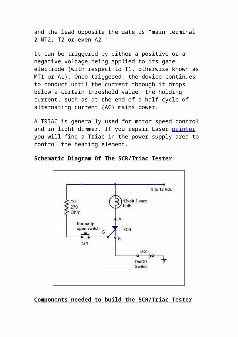
Components needed to build the SCR/Triac Tester 1- 1x circuit board2- 1x small box3- 3x grommets4- 3x 30cm wire5- 9 volt battery6- 9 volt battery holder7- 1x 270 ohm ¼ watt resistor8- 12 volt 3 watt light bulb9- 12 volt light bulb holder10- 3x test clips (preferably three different colors)11- 1x on/off switch12- 1x normally open switch (push to on switch)13- 4x circuit board screw holder You may also need:
1- A power drill to make holes in the circuit board and the small box.2- Double sided tape to secure the battery holder3- Sand paper to clean up the dirty layer on the circuit track4- Different color of wires5- A pen knife to cut off unwanted circuit track and6- Printed words or alphabet plus glue for labelling

7- Different part number of SCR and Triac for testing purposes.
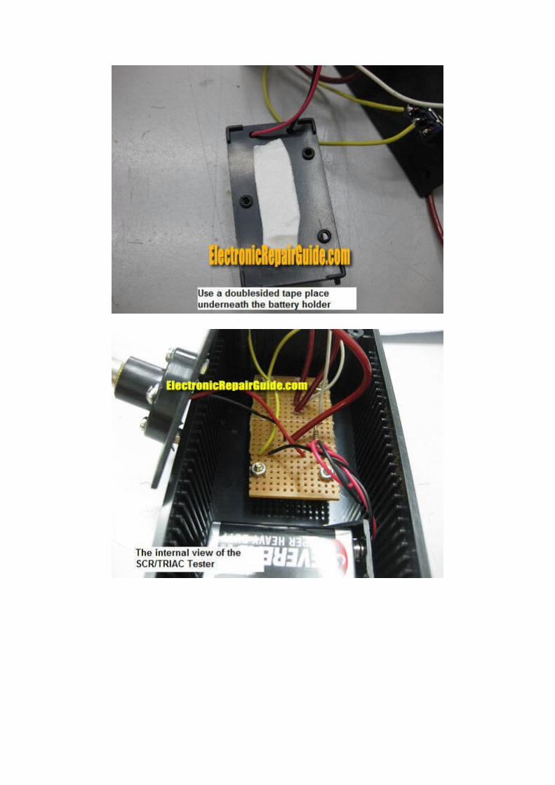
The procedure of fixing this tester can be seen from the photos below:


Testing SCR: Please click on the youtube video to see how I test the MCR100-6 SCR.
Testing Triac: The pinout of a Triac is usually T1 (MT1 or A1), T2 (MT2 or A2) and Gate (G). Just connect the test probes as follows: The 'K' probe to 'T1', the 'A' probe to 'T2' and the 'G' probe to 'GATE'. Turn on the switch and then press the Gate button on the tester and you should expect the lamp to light.
Conclusion- By having this tester you will not have doubt if the SCR or the Triac will breakdown when under load as compare to using multimeter to test it. By looking at the light bulb you can judge if the component is working or not. If there is a constant light you can be sure it is working. If the light have intermittent flashes and do not light at all then you can suspect that the component under test may have problem. I suggest that you compare with a known good working component for best result. If using 9 volt does not provide a good result to you then try use 12 vdc to retest and see the result. By the way , you have the choice on how you place the circuit board or components, this entirely depends on your preference and

not necessary have to follow the above design. Take care and may God always bless you and your family.