Embed Size (px)
Citation preview

INCREASING AVAILABILITY THROUGH ADVANCED GEARLESS DRIVE TECHNOLOGY
M. Combes1, C. Dirscherl
2, *T. Roesch
3
1Glencore Xstrata
Av. Apoquindo 3885
Santiago, Chile
2Siemens Industry Inc.
7810 Shaffer Parkway
Littleton, CO 80127, United States of America
3Siemens AG
Schuhstrasse 60
Erlangen, 90152, Germany
(*Corresponding author:[email protected])
ABSTRACT
Declining ore grade, leading to increased material transport and plant throughput requirements, is
one of the major challenges in the current mining environment. This is accompanied by rising energy and
labor costs, decreasing plant productivity and the requirement for highest plant availability. Siemens’
answer is the latest gearless drive technology for grinding and conveying. Gearless drive solutions are
surpassing the mechanical limits of conventional drive systems serving to utilize the principle of
economies of scale. By elimination of various components of the drive train the maintenance activities and
spare parts inventories are reduced. The advantages are culminating in the incomparable availability of the
Siemens’ gearless drive technology of 99.46 to 99.71% - as confirmed by real operational data from the
Antapaccay mine in Peru. It was the first plant worldwide to use gearless drives for both applications.
KEYWORDS
Gearless Mill Drives, Gearless Conveyor Drives, Availability,
SAG Mill, Ball Mill, Overland Conveyor, Antapaccay
15
46th Annual Canadian Mineral Processors Operators Conference©, Ottawa, Ontario, January 21-23, 2014
INTRODUCTION – THE GEARLESS PRINCIPLE
The principle idea behind a gearless drive system is to reduce the number of components and
diversity of parts. Especially those components that are at the edge of current manufacturing or power
limits are eliminated. The used equipment provides the possibility to scale up and increase the power
transmitted to the driven machine. This finally results in a possible increase of throughput respectively
transported or processed material.
In order to apply this principle of simplification we will take a look at the components of a
conventional drive system consisting of:
- Driven equipment (mill, conveyor, slurry pump…)
- Components altering the rated speed (gearboxes, girth gear / pinion)
- The electric motor
- Starting devices for the motor (VSD, CCV, LRS, clutch…), which are necessary because a direct
across-the-line start of high power motors with load would result in a significant drop in the line
supply voltage
- Alternatively a variable speed drive (VSD) or cycloconverter (CCV) to utilize the possibility of
speed variation during operation
- The electrical supply system (cables, switchgear, transformers, protection equipment)
Intermediate gearboxes are not required when a motor is used with a rated speed that directly
matches the speed requirement of the driven equipment. Furthermore the VSD can be used to smoothly
start the motor and to vary speed during operation, which means that it satisfies both requirements.
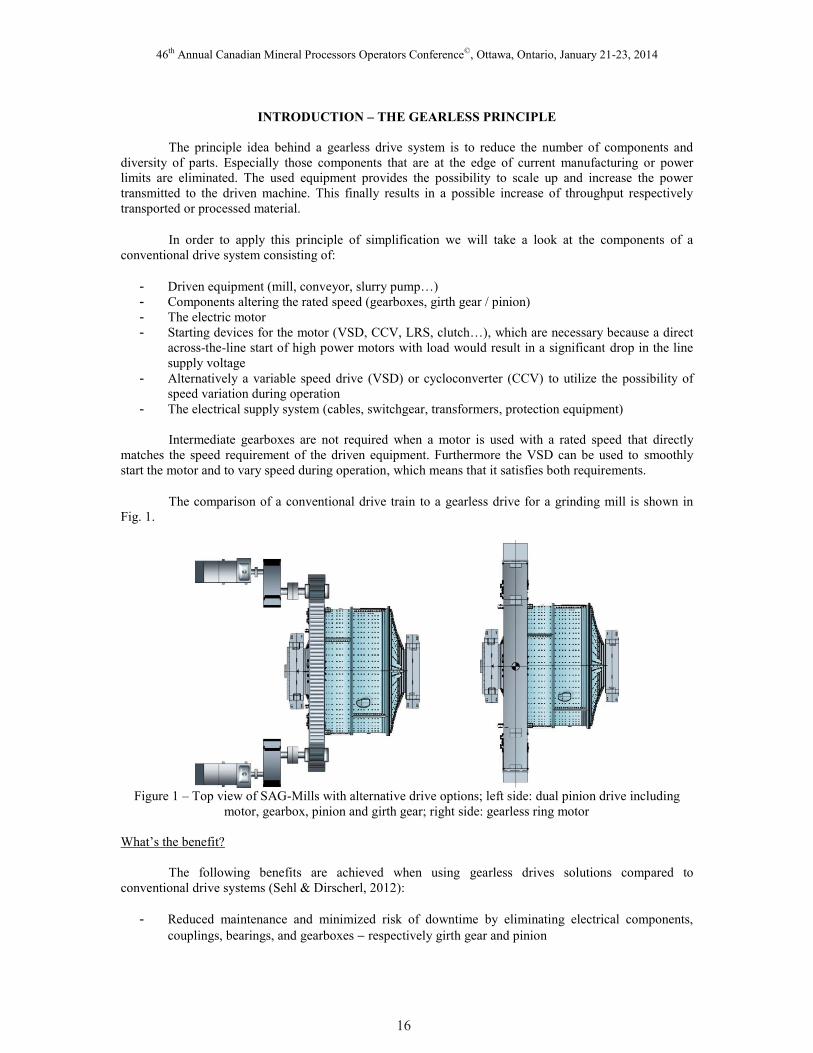
The comparison of a conventional drive train to a gearless drive for a grinding mill is shown in
Fig. 1.
Figure 1 – Top view of SAG-Mills with alternative drive options; left side: dual pinion drive including
motor, gearbox, pinion and girth gear; right side: gearless ring motor
What’s the benefit?
The following benefits are achieved when using gearless drives solutions compared to
conventional drive systems (Sehl & Dirscherl, 2012):
- Reduced maintenance and minimized risk of downtime by eliminating electrical components,
couplings, bearings, and gearboxes respectively girth gear and pinion
16
46th Annual Canadian Mineral Processors Operators Conference©, Ottawa, Ontario, January 21-23, 2014
- Higher plant productivity due to higher availability
- Up to (4) four percent higher energy efficiency – can be achieved with gearless drive technology
(at nominal power and speed)
- Higher available power at the driven component, surpassing the mechanical limits of systems with
gearboxes
- Fewer spare parts resulting in lower inventories
- Smaller footprint of complete drive train
- Lower operational expenses
- Critical open gear power trains are avoided (Dugalic & Tischler, 2009)
- Robust design (Dugalic & Tischler, 2009)
There are various applications within a typical mine site that can utilize gearless drive systems.
Starting along the process from the extraction, e.g. with mine winders, excavators or draglines further to
the material transport (conveying) and in the concentrator plant for the grinding mills and cyclone or slurry
pumps. In this paper, we focus on the ore grinding and conveying applications, for which the gearless
principle was expanded even further so that the motor and the mill respectively conveyor and pulley were
combined in such a way that the motor becomes an integral part of the driven machine. The details are
provided in the following sections.
GEARLESS DRIVES FOR LARGE ORE CONVEYORS
Over the past few years, belt conveyors that demand high drive power and performance are being
increasingly used. Due to the critical nature of these drive solutions, reliability and efficiency is essential;
ThyssenKrupp and Siemens favor a straightforward design with a limited amount of components to
accomplish this objective.
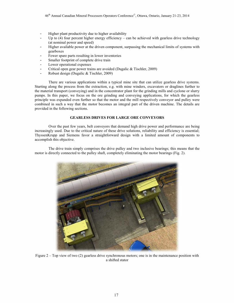
The drive train simply comprises the drive pulley and two inclusive bearings; this means that the
motor is directly connected to the pulley shaft, completely eliminating the motor bearings (Fig. 2).
Figure 2 – Top view of two (2) gearless drive synchronous motors; one is in the maintenance position with
a shifted stator
17
46th Annual Canadian Mineral Processors Operators Conference©, Ottawa, Ontario, January 21-23, 2014
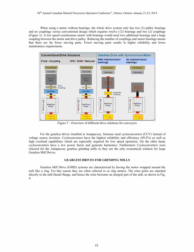
When using a motor without bearings, the whole drive system only has two (2) pulley bearings
and no couplings versus conventional design which requires twelve (12) bearings and two (2) couplings
(Figure 3). A low speed synchronous motor with bearings would need two additional bearings and a large
coupling between the motor and drive pulley. Reducing the number of couplings and motor bearings means
that there are far fewer moving parts. Fewer moving parts results in higher reliability and lower
maintenance requirements.
Figure 3 – Overview of different drive solutions for conveyors
For the gearless drives installed at Antapaccay, Siemens used cycloconverters (CCV) instead of
voltage source inverters. Cycloconverters have the highest reliability and efficiency (99.5%) as well as
high overload capabilities which are especially required for low speed operation. On the other hand,
cycloconverters have a low power factor and generate harmonics. Furthermore Cycloconverters were
selected for the Antapaccay gearless grinding mills as they are the only economical solution for large
Gearless Mill Drives.
GEARLESS DRIVES FOR GRINDING MILLS
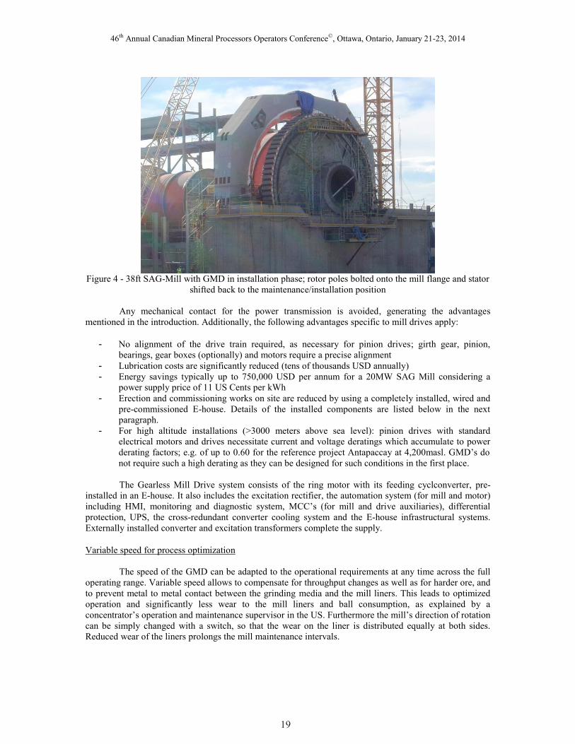
Gearless Mill Drive (GMD) systems are characterized by having the motor wrapped around the
mill like a ring. For this reason they are often referred to as ring motors. The rotor poles are attached
directly to the mill (head) flange, and hence the rotor becomes an integral part of the mill, as shown in Fig.
4.
18
46th Annual Canadian Mineral Processors Operators Conference©, Ottawa, Ontario, January 21-23, 2014
Figure 4 - 38ft SAG-Mill with GMD in installation phase; rotor poles bolted onto the mill flange and stator
shifted back to the maintenance/installation position
Any mechanical contact for the power transmission is avoided, generating the advantages
mentioned in the introduction. Additionally, the following advantages specific to mill drives apply:
- No alignment of the drive train required, as necessary for pinion drives; girth gear, pinion,
bearings, gear boxes (optionally) and motors require a precise alignment
- Lubrication costs are significantly reduced (tens of thousands USD annually)
- Energy savings typically up to 750,000 USD per annum for a 20MW SAG Mill considering a
power supply price of 11 US Cents per kWh
- Erection and commissioning works on site are reduced by using a completely installed, wired and
pre-commissioned E-house. Details of the installed components are listed below in the next
paragraph.
- For high altitude installations (>3000 meters above sea level): pinion drives with standard
electrical motors and drives necessitate current and voltage deratings which accumulate to power
derating factors; e.g. of up to 0.60 for the reference project Antapaccay at 4,200masl. GMD’s do
not require such a high derating as they can be designed for such conditions in the first place.
The Gearless Mill Drive system consists of the ring motor with its feeding cyclconverter, pre-
installed in an E-house. It also includes the excitation rectifier, the automation system (for mill and motor)
including HMI, monitoring and diagnostic system, MCC’s (for mill and drive auxiliaries), differential
protection, UPS, the cross-redundant converter cooling system and the E-house infrastructural systems.
Externally installed converter and excitation transformers complete the supply.
Variable speed for process optimization
The speed of the GMD can be adapted to the operational requirements at any time across the full
operating range. Variable speed allows to compensate for throughput changes as well as for harder ore, and
to prevent metal to metal contact between the grinding media and the mill liners. This leads to optimized
operation and significantly less wear to the mill liners and ball consumption, as explained by a
concentrator’s operation and maintenance supervisor in the US. Furthermore the mill’s direction of rotation
can be simply changed with a switch, so that the wear on the liner is distributed equally at both sides.
Reduced wear of the liners prolongs the mill maintenance intervals.
19
46th Annual Canadian Mineral Processors Operators Conference©, Ottawa, Ontario, January 21-23, 2014
Additionally, the following benefits result out of the flexibility with speed variation:
- Mill speed can be adapted to upstream and downstream processes - avoids overgrinding, and
optimizes load distribution between SAG and ball mill (Mular, Halbe, & Barratt, 2002).
- Power consumption is influenced by load respectively torque and mill speed. This means that
further energy can be saved if a mill speed below the rate speed is required.
- Speed adjustment to worn liners results in optimized throughput and less wear of grinding media
as cited by a representative of a German mill supplier representative
- Ball mill speed can be reduced during short maintenance measures e.g. inspections of the SAG
mill. This avoids time taking grinding out of the ball mill. Ball mills with fixed speed pinion
drives have to be stopped with a prior grinding out / drain out process before interruption and the
necessary time to restart. As a consequence variable speed capability helps the operator to reduce
downtime. This is confirmed by an operation and maintenance supervisor at a large Chilean
copper mine.
- Rather than adjustment of the ball charge to suit harder or softer ore entering the mill it is far more
practical to adjust the speed – as stated by a senior process engineer of an Australian EPCM.
- Reduced short circuit level required at the electrical network. This is in contrast to direct across
the line starting of large synchronous motors, which can generate disturbances to other grid users
when the mill starts. These disturbances are caused by large inrush currents and resulting line
voltage drop.
Operation modes ensure easy operation and minimize mill downtime
Operation of the GMD is very simple. It is facilitated - either fully automatic or manually - for
remote control from the operators’ central control room, at the E-house which is forming part of the GMD
system, or directly at the mill from the local control panel. Operators and maintenance personnel are
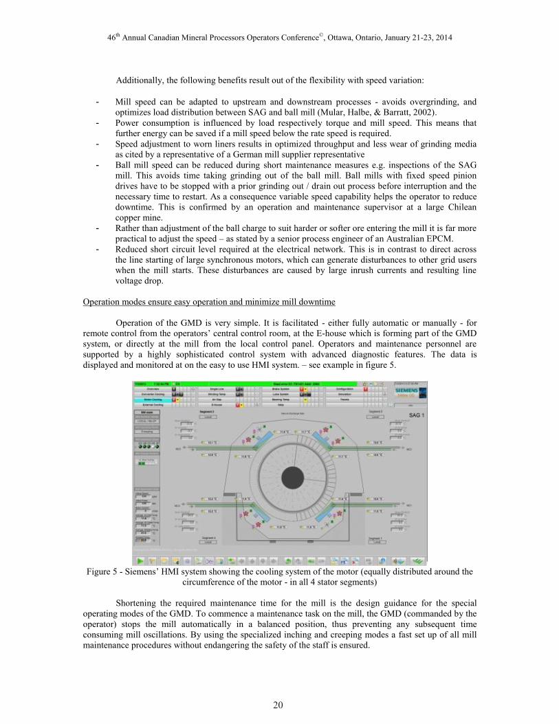
supported by a highly sophisticated control system with advanced diagnostic features. The data is
displayed and monitored at on the easy to use HMI system. – see example in figure 5.
Figure 5 - Siemens’ HMI system showing the cooling system of the motor (equally distributed around the
circumference of the motor - in all 4 stator segments)
Shortening the required maintenance time for the mill is the design guidance for the special
operating modes of the GMD. To commence a maintenance task on the mill, the GMD (commanded by the
operator) stops the mill automatically in a balanced position, thus preventing any subsequent time
consuming mill oscillations. By using the specialized inching and creeping modes a fast set up of all mill
maintenance procedures without endangering the safety of the staff is ensured.
20
46th Annual Canadian Mineral Processors Operators Conference©, Ottawa, Ontario, January 21-23, 2014
In the inching mode the maintenance operator selects the desired angle to turn the mill (e.g. 90° -
referred to as angle X). The automatic controller accelerates the mill to 1 rpm. In order to stop the mill in a
balanced position, the GMD overturns this desired angle of the mill by the additional angle that the charge
requires to cascade (angle Y). When this calculated angle is reached, which is required to balance the mill
(angle X + Y), the GMD automatically changes the direction of rotation and turns the mill back to the
requested angle X, thereby stopping without oscillations. The brake is automatically applied.
Creeping at 0.3 rpm is useful for slow movements, which the maintenance operator can observe
directly by standing next to or in front of the mill. This allows to precisely trim the mill to a certain
position. Operated from a handheld local control, with a simple push button, the GMD lifts the charge in
the selected direction. The pushbutton is released to stop movement; the GMD holds the load and then
applies the brake. The movement can be repeated as required, which is very useful for mill or liner
inspections. As the mill stops in an unbalanced position the mill can be balanced out easily by switching
over to the balancing mode.
A “frozen” or “baked” charge is capable of severely damaging or destroying the mill body and/or
bearings when dropping from the top of the mill after a 180° rotation. The resulting damage and its
consequential production losses are tremendous and could amount to millions of USD. In order to prevent
this risk the Frozen Charge Protection® was developed. In normal operation, the charge starts to slide or
cascade after the mill reaches a certain rotation angle of between 40° and 70° and the load torque
noticeably dips. At every start the system closely monitors this torque dip behavior. Surpassing certain
torque limits the system detects the frozen charge and stops the mill safely before any damage to the mill
occurs.
This controlled mill stopping prevents damage, but does not completely solve the problem. After
stopping the mill, the charge remains in a “frozen” condition and must be broken up mechanically or by
flushing with water. This takes time and causes production losses of multiple hours or even days. The
Frozen Charge Shaker™ from Siemens provides the solution. It has the capability to automatically break
up the frozen charge and remove it from the mill body. The Frozen Charge Shaker™ lifts the charge to a
risk-free angle, and shakes the mill with varying speed and acceleration. The angle and movement are
designed to break the frozen charge and remove it safely from the mill body. This whole procedure only
takes a few minutes.
The required high precision for the movements is achieved by using an enhanced tachometer with
the appropriate high resolution.
Gearless Mill Drives to assure high productivity and operational reliability
In conjunction with the mill dedicated operation modes the Siemens GMD provides a variety of
additional features which are oriented to keep the production time of the grinding mill as high as possible.
- Using a remote access connection maintenance personnel can be assisted by experts either from
the factory or from worldwide service hubs who connect to the plant network via online secure
communication. After permission is granted, manufacturer’s experts can securely enter the
automation system with the highly sophisticated diagnostic system. It provides the user and the
supplier’s experts with the required data to monitor the equipment condition, compare it with
historical data, derive trends, identify abnormalities, conclude preventive maintenance measures
and conduct corrective maintenance. Furthermore it also eases commissioning work or any kind of
update or upgrade works.
- A short-circuit proof design is an important characteristic for electrical systems, as it is not
possible to completely avoid short circuits. This requirement is met by various measures. For
example the cycloconverter utilizes thyristors designed to extinguish short circuit currents. The
motor on the other hand has proven its mechanical and electrical withstand capability to short
circuit forces in several events already. The benefit for the users is that the GMD system can
21
46th Annual Canadian Mineral Processors Operators Conference©, Ottawa, Ontario, January 21-23, 2014
resume normal operation at the earliest e.g. on the cycloconverter fuses or other components do
not have to be replaced. Further details on this requirement have been published on many
occasions for example by Kümmlee & Meinke (2001), by Tischler (2003), or by Diaz, Errath &
Riquelme (2004).
- The structural design of the motor provides the optimum balance of highest stiffness at a
reasonable motor weight. For proper examination of the mechanical design every GMD undergoes
a highly sophisticated FEM analysis. This not only takes into consideration the motor but also the
mill body, bearings, foundation and soil to assure an integral approach. User’s main benefit of this
robust design is the withstanding of any arising mechanical forces - also for extreme conditions
like earthquakes, where Siemens fulfills the stringent UBC, Zone 4 requirements.
- Numerous additional features combined with stringent manufacturing quality standards and the
high level design know-how have been continuously developed over 30 years of experience in the
field of Gearless Mill Drives for the mining industry. Discussing all of these features in detail
would exceed the scope of the paper and can be provided individually by approaching the
corresponding author. Siemens has one main focus for this continuous development and
improvement process – namely to maximize the uptime of the user’s grinding circuit. An excellent
case study of the operational experience with recently installed Gearless Mill Drives and Gearless
Conveyors at the Antapaccay mine in Peru is illustrated in the next section.
ANTAPACCAY – THE FIRST MINE UTILIZING GEARLESS CONVEYOR AND GEARLESS
MILL DRIVES
The Antapaccay mine
Antapaccay is a brownfield expansion project of the Tintaya copper mine, located at 4,200m
above sea level in the Cusco region of the Peruvian Andeans. The mine pertaining to Glencore Xstrata
comprises new mine facilities, material transport equipment and a new 70ktpd concentrator, while utilizing
some of the existing Tintaya infrastructure. The deposit, with an estimated mineral resource of over
1,000Mt at 0.49% Cu using a cut-off grade of 0.15% Cu, is scheduled to produce annually 160,000 tons of
copper in concentrate in the first few years of its minimum 20 years mine life (Mining Journal, 2012). The
plant started up on time and delivered its first concentrate in November 2012. In May 2013 the
concentrator reached its design capacity and is now operating 10% above this level.
ThyssenKrupp and Siemens supplied the 6.5km overland conveyor to transport the copper ore
from the mine to the processing plant. The conveyor has a 1,370mm wide belt, travels at 6.2m/s and has a
design capacity of up to 5,260 tons of ore per hour. It is featured with the innovative gearless drives system
providing a power output of 3,800kW on each of the two (2) drive pulleys. Both drive systems are located
at the same drive station.
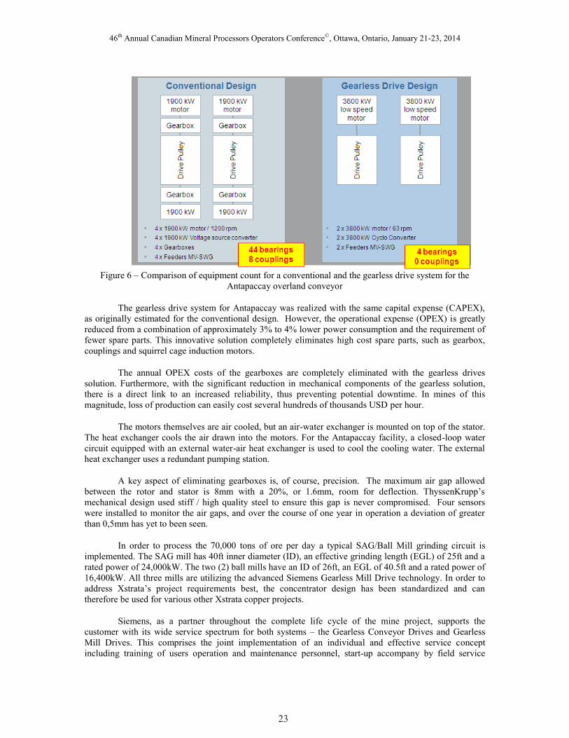
Antapaccay was initially designed with a conventional drive system: Variable frequency inverters
with squirrel cage induction motors together with couplings and gearboxes. The design comprised four (4)
motors with 1900kW each. The gearless drives system in comparison uses only two (2) drive pulleys, each
with a 3800kW rating.. Hence only two Cycloconverters and two medium voltage switchgears were
needed as opposed to the original four VFD’s and four medium voltage switchgears. By reducing the
electrical equipment, the E-house footprint was half of the original size. From the mechanical side, the
gearless drives now only require the maintenance attention of four pulley bearings instead of 48 bearings
and 8 couplings. This can be seen in Fig. 6.
22
46th Annual Canadian Mineral Processors Operators Conference©, Ottawa, Ontario, January 21-23, 2014
Figure 6 – Comparison of equipment count for a conventional and the gearless drive system for the
Antapaccay overland conveyor
The gearless drive system for Antapaccay was realized with the same capital expense (CAPEX),
as originally estimated for the conventional design. However, the operational expense (OPEX) is greatly
reduced from a combination of approximately 3% to 4% lower power consumption and the requirement of
fewer spare parts. This innovative solution completely eliminates high cost spare parts, such as gearbox,
couplings and squirrel cage induction motors.
The annual OPEX costs of the gearboxes are completely eliminated with the gearless drives
solution. Furthermore, with the significant reduction in mechanical components of the gearless solution,
there is a direct link to an increased reliability, thus preventing potential downtime. In mines of this
magnitude, loss of production can easily cost several hundreds of thousands USD per hour.
The motors themselves are air cooled, but an air-water exchanger is mounted on top of the stator.
The heat exchanger cools the air drawn into the motors. For the Antapaccay facility, a closed-loop water
circuit equipped with an external water-air heat exchanger is used to cool the cooling water. The external
heat exchanger uses a redundant pumping station.
A key aspect of eliminating gearboxes is, of course, precision. The maximum air gap allowed
between the rotor and stator is 8mm with a 20%, or 1.6mm, room for deflection. ThyssenKrupp’s
mechanical design used stiff / high quality steel to ensure this gap is never compromised. Four sensors
were installed to monitor the air gaps, and over the course of one year in operation a deviation of greater
than 0,5mm has yet to been seen.
In order to process the 70,000 tons of ore per day a typical SAG/Ball Mill grinding circuit is
implemented. The SAG mill has 40ft inner diameter (ID), an effective grinding length (EGL) of 25ft and a
rated power of 24,000kW. The two (2) ball mills have an ID of 26ft, an EGL of 40.5ft and a rated power of
16,400kW. All three mills are utilizing the advanced Siemens Gearless Mill Drive technology. In order to
address Xstrata’s project requirements best, the concentrator design has been standardized and can
therefore be used for various other Xstrata copper projects.
Siemens, as a partner throughout the complete life cycle of the mine project, supports the
customer with its wide service spectrum for both systems – the Gearless Conveyor Drives and Gearless
Mill Drives. This comprises the joint implementation of an individual and effective service concept
including training of users operation and maintenance personnel, start-up accompany by field service
23
46th Annual Canadian Mineral Processors Operators Conference©, Ottawa, Ontario, January 21-23, 2014
engineers on site, predictive and preventive maintenance with remote data analysis, 24/7 on-call service as
a helpdesk with remote diagnosis, spare parts monitoring and annual preventive maintenance visits by
specialists from the factory.
In addition the Siemens’ scope of supply also included the main electrical distribution equipment,
namely the 220kV high voltage gas insulated switchgear, 33kV medium voltage gas insulated switchgear
and the low voltage distribution.
Most important operational data – availability
Availability is an absolute key figure for mineral processing plants. In the specific case of
Antapaccay every hour of downtime would lead to far more than 100,000.- USD of production loss based
on current CU market prices. In order to facilitate a common understanding of availability, we first define
this KPI as a metric for operational productivity.
Availability - definition
Essentially it is the ratio of the operation time of a machine over the time a machine is expected to
be available and ready for operation. With regard to grinding and material transport equipment with all of
their respective drives, many users factor in all unavailable hours of the mill or belt conveyor including its
planned maintenance time. (Tischler & Kennedy, 2011)
In this paper we focus on the availability of the gearless drive system with all of its auxiliaries.
Then there are different approaches within the industry on how to treat planned maintenance measures. The
first possibility is to consider all maintenance down times – independent of their nature – as unavailable
time of the gearless drive equipment. The resulting equation uses a denominator of 365 days or 8,760 hours
for calculating the availability ratio for one year (see equation no. 1). However, usually the scheduled
maintenance measures of the gearless drive are accommodated within the time frames for planned
maintenance of the mechanical equipment; e.g. for liner exchange or idler / chute maintenance. Therefore
additional downtime for the purpose of drive maintenance is not required. Consequently the planned
mechanical downtime and the preventive maintenance measures during that time would be excluded from
the availability equation of the gearless drives, since the gearless drives are not expected to be fully
available during these periods. Experience indicates that the resulting denominator then varies between 345
and 355 days per year for grinding mills respectively 320 to 330 days for long overland conveyors.
The approach used at Antapaccay is first one with the following formula:
Availability = (8,760 hours per year – hours for preventive and corrective maintenance of the gearless
drive system)*100 / 8,760 hours per year (1)
Having defined the KPI we will subsequently take a look at the real data of the Antapaccay mine.
Availability figures for the Gearless Conveyor Drive
As the plant started up in late 2012, we will consider the availability data for the first months of
continuous operation from January to August 2013 (being the last month available at copy date for this
paper). The Gearless Conveyor Drive system required a total preventive maintenance time of 23.0 hours
during that period, whereas the system comprises of 2 (two) synchronous motors with their respective
cycloconverters installed in the pre-commissioned E-house which also accommodates the excitation
system, automation and diagnostic system and the MCC’s for the auxiliaries of the complete drive station.
Converter transformers as well as the corresponding internal and external cooling systems are also
considered part of the system. All the preventive tasks for this drive equipment were carried out when the
conveyor was down for other maintenance measures anyway. Additionally, corrective maintenance work
was performed in the same time frame from January to August 2013. This is a total of 8.4 hours.
24
46th Annual Canadian Mineral Processors Operators Conference©, Ottawa, Ontario, January 21-23, 2014
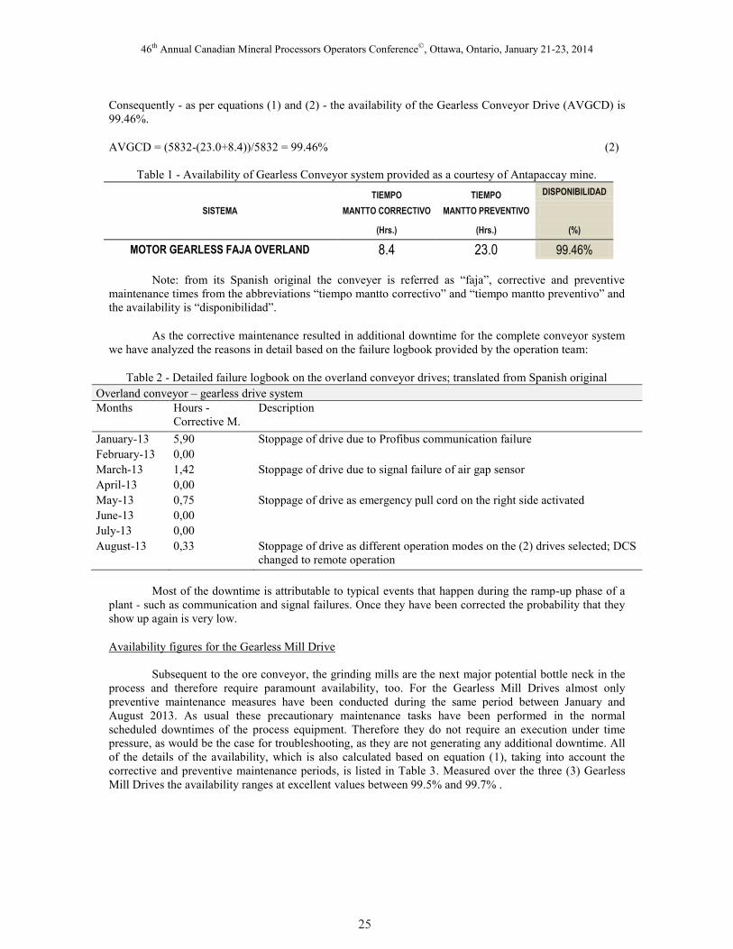
Consequently - as per equations (1) and (2) - the availability of the Gearless Conveyor Drive (AVGCD) is
99.46%.
AVGCD = (5832-(23.0+8.4))/5832 = 99.46% (2)
Table 1 - Availability of Gearless Conveyor system provided as a courtesy of Antapaccay mine.
SISTEMA
TIEMPO TIEMPO DISPONIBILIDAD
MANTTO CORRECTIVO MANTTO PREVENTIVO
(Hrs.) (Hrs.) (%)
MOTOR GEARLESS FAJA OVERLAND 8.4 23.0 99.46%
Note: from its Spanish original the conveyer is referred as “faja”, corrective and preventive
maintenance times from the abbreviations “tiempo mantto correctivo” and “tiempo mantto preventivo” and
the availability is “disponibilidad”.
As the corrective maintenance resulted in additional downtime for the complete conveyor system
we have analyzed the reasons in detail based on the failure logbook provided by the operation team:
Table 2 - Detailed failure logbook on the overland conveyor drives; translated from Spanish original
Overland conveyor – gearless drive system
Months Hours -
Corrective M.
Description
January-13 5,90 Stoppage of drive due to Profibus communication failure
February-13 0,00
March-13 1,42 Stoppage of drive due to signal failure of air gap sensor
April-13 0,00
May-13 0,75 Stoppage of drive as emergency pull cord on the right side activated
June-13 0,00
July-13 0,00
August-13 0,33 Stoppage of drive as different operation modes on the (2) drives selected; DCS
changed to remote operation
Most of the downtime is attributable to typical events that happen during the ramp-up phase of a
plant - such as communication and signal failures. Once they have been corrected the probability that they
show up again is very low.
Availability figures for the Gearless Mill Drive
Subsequent to the ore conveyor, the grinding mills are the next major potential bottle neck in the
process and therefore require paramount availability, too. For the Gearless Mill Drives almost only
preventive maintenance measures have been conducted during the same period between January and
August 2013. As usual these precautionary maintenance tasks have been performed in the normal
scheduled downtimes of the process equipment. Therefore they do not require an execution under time
pressure, as would be the case for troubleshooting, as they are not generating any additional downtime. All
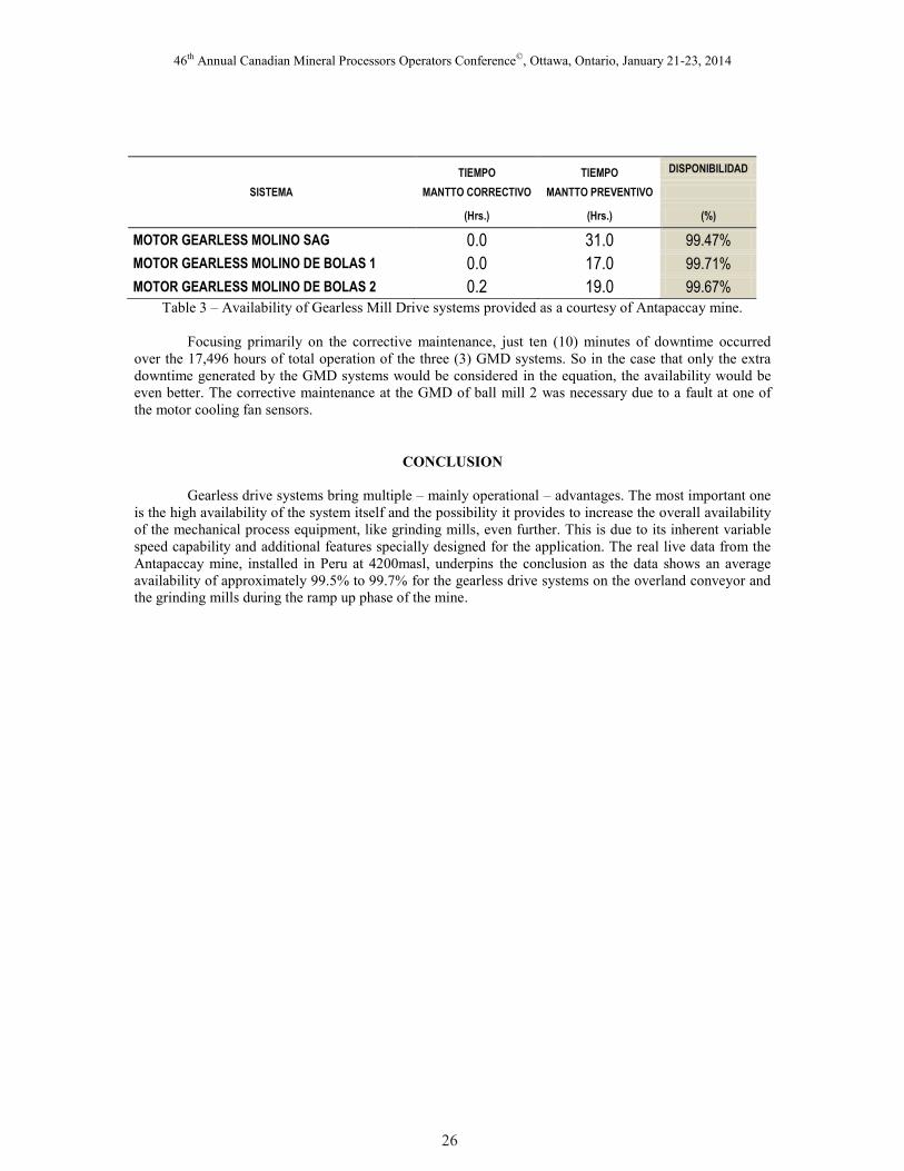
of the details of the availability, which is also calculated based on equation (1), taking into account the
corrective and preventive maintenance periods, is listed in Table 3. Measured over the three (3) Gearless
Mill Drives the availability ranges at excellent values between 99.5% and 99.7% .
25
46th Annual Canadian Mineral Processors Operators Conference©, Ottawa, Ontario, January 21-23, 2014
SISTEMA
TIEMPO TIEMPO DISPONIBILIDAD
MANTTO CORRECTIVO MANTTO PREVENTIVO
(Hrs.) (Hrs.) (%)
MOTOR GEARLESS MOLINO SAG 0.0 31.0 99.47%
MOTOR GEARLESS MOLINO DE BOLAS 1 0.0 17.0 99.71%
MOTOR GEARLESS MOLINO DE BOLAS 2 0.2 19.0 99.67% Table 3 – Availability of Gearless Mill Drive systems provided as a courtesy of Antapaccay mine.
Focusing primarily on the corrective maintenance, just ten (10) minutes of downtime occurred
over the 17,496 hours of total operation of the three (3) GMD systems. So in the case that only the extra
downtime generated by the GMD systems would be considered in the equation, the availability would be
even better. The corrective maintenance at the GMD of ball mill 2 was necessary due to a fault at one of
the motor cooling fan sensors.
CONCLUSION
Gearless drive systems bring multiple – mainly operational – advantages. The most important one
is the high availability of the system itself and the possibility it provides to increase the overall availability
of the mechanical process equipment, like grinding mills, even further. This is due to its inherent variable
speed capability and additional features specially designed for the application. The real live data from the
Antapaccay mine, installed in Peru at 4200masl, underpins the conclusion as the data shows an average
availability of approximately 99.5% to 99.7% for the gearless drive systems on the overland conveyor and
the grinding mills during the ramp up phase of the mine.
26
46th Annual Canadian Mineral Processors Operators Conference©, Ottawa, Ontario, January 21-23, 2014
REFERENCES
Diaz, R., Errath, R. & Riquelme, C., (2004): Desplazamiento horizontal del estator de un gearless mill
drive producto de una falla eléctrica [Horizontal displacement of a stator of a gearless mill drive as a
consequence of an electrical fault], MAPLA 2004. Chile
Dugalic, M. & Tischler, K., (2009): Gearless mill drives, Machinery risk solution practice
Kümmlee, H. & Meinke, P., (2001): A mechatronic solution, Design experience with large Gearless Mill
Drives. Germany
Mining Journal (2012): retrieved from: http://www.mining-journal.com/production-and-markets/xstrata-
dispatches-first-antapaccay-copper-concentrate
Mular, A., Halbe, D. & Barratt, D. (2002): Mineral Processing Plant Design, Practice and Control, SME.
Littleton – USA
Sehl, P. & Dirscherl, C., (2012): Modern gearless drive systems for high capacity belt conveyors, Inpit
Crushing and Conveying
Tischler, K., (2003): The behavior of the cycloconverter fed gearless drive under abnormal electrical
conditions, Workhsop SAG 2003. Chile
Tischler, K. & Kennedy, T., (2011): Availability and Reliability of Siemens’ gearless drives, SAG
Conference. Vancover – Canada
27