Embed Size (px)
Citation preview
8/3/2019 Gearless Wind Generator Owner's Manual
http://slidepdf.com/reader/full/gearless-wind-generator-owners-manual 1/46
HONEYWELL™ Wind Turbine
Model WT6500
The HONEYWELL™ trademark is used under license from Honeywell
International Inc.
Honeywell International Inc. makes no representations, or warranties withrespect to this product or service.
Owner’s Manual

8/3/2019 Gearless Wind Generator Owner's Manual
http://slidepdf.com/reader/full/gearless-wind-generator-owners-manual 2/46
II
HONEYWELL™ Wind Turbine WT6500 Owner’s Manual - Rev10
Thank You!Thank you for your purchase of this award winning turbine, and welcome to the Age of Renewable Energy.
Thank you for your purchase of the HONEYWELL™ Wind Turbine. It is one of the most advanced wind turbine
systems in the world. We are proud to offer a cost effective renewable energy technology that will provide you
with many years of electric generation from an available and abundant resource; the wind. Our technology has
received the prestigious Gold Edison Award in 2010 and the Breakthrough Technology Award for 2009 fromPopular Mechanics. By purchasing and installing this product you have demonstrated your desire to reduce
carbon dioxide emission and play a role in energy conservation.
Please take a moment to complete and return to us the Warranty Registration Card.
Serial Number __________________________________
Model Number __________________________________
Please note that the Warranty depends on the proper installation of the HONEYWELL™ Wind Turbine. Please
read this Owner’s Manual carefully and always use licensed and trained personnel for its proper installation.
The HONEYWELL™ Wind Turbine is manufactured by WindTronics. Please contact WindTronics at:
621 Sprucewood Avenue
Windsor, Ontario
N9C 0B3
877-946-3898
The Honeywell Trademark is used under license from Honeywell International Inc.
Honeywell International Inc. makes no representations or warranties with respect to this product.

8/3/2019 Gearless Wind Generator Owner's Manual
http://slidepdf.com/reader/full/gearless-wind-generator-owners-manual 3/46
I
HONEYWELL™ Wind Turbine WT6500 Owner’s Manual - Rev10
8/3/2019 Gearless Wind Generator Owner's Manual
http://slidepdf.com/reader/full/gearless-wind-generator-owners-manual 4/46
III Safety Information
HONEYWELL™ Wind Turbine WT6500 Owner’s Manual - Rev 10
Safety InformationPLEASE READ THESE INSTRUCTIONS AND THE ENTIRE MANUAL PRIOR TO INSTALLATION.
INSTALLATION OF THIS WIND TURBINE CAN ONLY BE PERFORMED BY A LICENSED AND TRAINED
PROFESSIONAL.
Safety Icons
The following symbols identify dangers associated with the installation, use or
ownership of the HONEYWELL™ Wind Turbine. When you see the symbols be aware
of the protocol for personal injury or property damage.
WARNING indicates a hazard that could result in death,
personal injury or property damage.
CAUTION indicates a hazard that could result in property
damage.
IMPORTANT: PLEASE TAKE NOTE
PROFESSIONAL INSTALLATION: REQUIRED
TIP: Helpful information to ease the installation
Important Safety Instructions
1. This Owner’s Manual contains important instructions for the HONEYWELL™ Wind
Turbine installation and maintenance. Please save it.
2. Read the entire Owner’s Manual prior to installation and follow all warnings and
cautions included in the Owner’s Manual and/or attached to the HONEYWELL™ Wind
Turbine.
3. Improper installation, adjustment, alteration, service maintenance, or use can causere, electrical shock, or other conditions which may cause death, personal injury or
property damage.
4. The use of a licensed and trained professional for the installation and maintenance of
the HONEYWELL™ Wind Turbine is required.
8/3/2019 Gearless Wind Generator Owner's Manual
http://slidepdf.com/reader/full/gearless-wind-generator-owners-manual 5/46
IV
HONEYWELL™ Wind Turbine WT6500 Owner’s Manual - Rev 10
DO NOT CONNECT THE HONEYWELL WIND
TURBINE TO ANY CONTROLLER OTHER THAN THE
SMARTBOX™ Controller OR OTHER CONTROLLER
PRE-APPROVED, IN WRITING, BY WINDTRONICS.
Failure to follow this warning will void the HONEYWELL™
Wind Turbine warranty and may result in death, personal
injury or property damage (including damage to theHONEYWELL™ Wind Turbine).
5. Choose a very calm, nearly no wind, day for the installation.
6. Follow the installation procedures contained within this Owner’s Manual and all safety
codes. Follow the National Electric Code (NEC) and your local building zoning and
zoning codes. In Canada, follow the Canadian Electrical Code (CEC).
7. Only licensed and trained personnel should move and lift the HONEYWELL™ Wind
Turbine. The HONEYWELL™ Wind Turbine should only be moved using standard
hoists and hydraulic lifts.
8. Appropriate protective personal equipment such as hard hat, work gloves,
safety glasses, and closed toe work shoes should be worn when installing the
HONEYWELL™ Wind Turbine.
9. Only licensed and trained personnel can perform the following maintenance functions
on this HONEYWELL™ Wind Turbine:
• Open and work on the SMARTBOX™ Control Equipment.
• Open and work on the Junction Box at the turbine
• Apply any torque to any of the turbine’s fasteners
10. The installation directions include recommendations of a variety of options. Installation
must be approved and certied by your local Professional Engineer (PE) and the
installer must acquire all the necessary permits from the local authorities prior to
installation.
11. Your installer must use only proper grounding methods as stipulated by the NEC or
CEC if in Canada.
12. The HONEYWELL™ Wind Turbine is an electric generator. Therefore high voltage
is generated within the system. Be sure to only use installers and maintenance
professionals to perform work on this turbine.
13. Failure to complete and mail in the registration card will affect the Warranty.
14. Failure to use a licensed and trained installer or follow local codes will
adversely affect the warranty coverage and possibly void your
warranty.
NOTE TO INSTALLER: This Owner’s Manual should be left with the owner of the
HONEYWELL™ Wind Turbine.
8/3/2019 Gearless Wind Generator Owner's Manual
http://slidepdf.com/reader/full/gearless-wind-generator-owners-manual 6/46
V Table of Contents
HONEYWELL™ Wind Turbine WT6500 Owner’s Manual - Rev 10
Table of Contents
Safety Instructions III
1. Introduction
Product Description................................................................ 2
Shipping Contents.................................................................. 2
Before Installing the HONEYWELL™ Wind Turbine.............. 3
Lift Point.................................................................................. 4
2. Turbine Mounting and WiringTurbine Mounting:
Introduction............................................................................. 6
Turbine with Electrical Systems................................................ 8
Site Selection.......................................................................... 8
Mounting Options................................................................... 10
Pole Mount......................................................................... 11
QUADPOD™ Mount............................................................. 11
ROOFBOX™ Mount............................................................. 11
Balast Mount....................................................................... 12
Turbine Wiring:
Wiring...................................................................................... 12
The SMARTBOX Controller.................................................... 14
The Battery Box...................................................................... 15
Recommended Battery Types................................................. 15
The Junction Box.................................................................... 16
Junction Box Block Diagram................................................... 17
Turbine Wiring Overview Diagram........................................... 18
DC Power Wiring Diagram...................................................... 19
Turbine Wiring and Distances................................................. 19
Turbine Current Rating and Wiring........................................... 19
Turbine Over-current Protection.............................................. 20Control Wiring..................................................................... 21
Grounding............................................................................... 22
Operation................................................................................ 23
8/3/2019 Gearless Wind Generator Owner's Manual
http://slidepdf.com/reader/full/gearless-wind-generator-owners-manual 7/46
V
HONEYWELL™ Wind Turbine WT6500 Owner’s Manual - Rev 10
Table of Contents
3. SpecifcationsTechnical Specications......................................................... 25
4. Warranty Information 27
5. AppendixPole Mount Drawing............................................................... 32
ROOFBOX™ Mount Drawing................................................. 33
ROOFBOX™ with QUADPOD™ Mount Drawing.................. 34
Ballast Mount Drawing............................................................ 35
One Line Drawing................................................................... 36
8/3/2019 Gearless Wind Generator Owner's Manual
http://slidepdf.com/reader/full/gearless-wind-generator-owners-manual 8/46
1 Introduction
HONEYWELL™ Wind Turbine WT6500 Owner’s Manual - Rev 10
Introduction
Chapter 1 describes the HONEYWELL™ Wind Turbine.
For Information On: See:
Product Description 2
Shipping Contents 2
Before Installation 3Lift Point 4
1
8/3/2019 Gearless Wind Generator Owner's Manual
http://slidepdf.com/reader/full/gearless-wind-generator-owners-manual 9/46
2
HONEYWELL™ Wind Turbine WT6500 Owner’s Manual - Rev 10
Introduction
Product Description
The HONEYWELL™ Wind Turbine is a novel electric generator (Worldwide patents
pending). It consists, as shown in the product detailed schematic, of a central wheel
made of aluminum rim, stainless steel spokes, and aluminum hub. Two ceramic
bearings are used to attach this wheel to the center shaft of the turbine. Custom-
shaped glass-lled nylon blades are attached to the spokes of this wheel. Permanentmagnets are afxed to the tips of these blades at the rim of the wheel.
The wind ows through this wheel with ease and it interacts with the aerodynamically
designed blades to induce a rotational motion in the wheel around its center hub. This
rotational motion is THE indication that wind energy is being extracted from the owing
wind stream. The magnets travel at a much higher speed for any given wheel rotation
because they are located at the rim of the wheel. This placement of the permanent
magnets at the blade tips produces the needed high speed motion without the need
of any gearing mechanism. The elimination of gears in this wind turbine technology
enhances wind energy extraction efciency and prolongs its operating life.
The permanent magnets at the blade tips and wheel rim travel at high speed within a
novel and custom-built stator system. This stator system converts the motion of thesemagnets into electricity. A glass-lled nylon aerodynamically shaped shroud covers the
stator system.
An anemometer is attached to the HONEYWELL™ Wind Turbine that produces near
instantaneous readings of wind speed and direction at the point of installation.
The electric output of the stator system is a variable direct current (DC) and is
connected together with the anemometer wind speed and direction outputs to the
HONEYWELL™ Wind Turbine SMARTBOX™ Control Equipment.
The SMARTBOX™ Control Equipment contains custom electronic battery charging
circuits, an inverter, and a transfer switch. The SMARTBOX™ Control Equipment
also employs a microprocessor which is programmed for optimal electric energyextraction from the wind, battery charge management, and automatically controls the
transmission of electricity via the transfer switch from the Grid (switch board) or the
attached battery (Not included).
Shipping Contents
1. One HONEYWELL™ Wind Turbine
2. Two (2) Wind Deectors with four (4) brackets attached and eight (8) ¼”-20 S.S.
locknuts
3. One (1) Deector installation instruction manual
4. One (1) Wind Turbine inspection certicate Tag
5. One (1) Junction Box assembly including:
• Wire harness connected to Wind Turbine which includes two (2) 14 AWG
Black wire and one (1) 12 AWG Green wire
• Davis instrument anemometer model 7911
8/3/2019 Gearless Wind Generator Owner's Manual
http://slidepdf.com/reader/full/gearless-wind-generator-owners-manual 10/46
3 Introduction
HONEYWELL™ Wind Turbine WT6500 Owner’s Manual - Rev 10
Before Installing the HONEYWELL™ Wind Turbine:
IMPORTANT
Please take note that the HONEYWELL™ Wind Turbine is a proprietary wind driven
electric generator. It is designed to displace annual electric consumption by connectingit to the electric switch board in the proper procedures described in this Owner’s
Manual. It may also be used on a stand-alone installation where connecting to a local
electric grid is not possible. Its unique and high efciency design enable it to work in
very low wind areas starting at 2 miles per hour (mph) and much higher (to 38 mph).
Please follow the Site Selection guidelines for optimal installation.
The HONEYWELL™ Wind Turbine is an electric generator. Only licensed and trained
personnel can perform the following installation and maintenance functions:
• Open and work on the SMARTBOX™ Control Equipment.
• Open and work on the Junction Box at the turbine
• Apply any torque to any of the turbine’s fasteners
The installation directions include recommendations of a variety of options. Installation
must be approved and certied by your local Professional Engineer (PE) and the
installer must acquire all the necessary permits from the local authorities prior to
installation.
Your installer must use only proper grounding methods as stipulated by the NEC or
CEC if in Canada.
The HONEYWELL™ Wind Turbine is an electric generator. Therefore high voltage
is generated within the system. Be sure to only use installers and maintenance
professionals to perform work on this turbine.
Failure to complete and mail in the registration card will affect the Warranty.
Failure to use a licensed and trained installer or follow local codes will
adversely affect the warranty coverage and possibly void your
warranty.
Please contact WindTronics if there is any doubt or concern regarding this electric
generator or its installation.
1-877-946-3898
8/3/2019 Gearless Wind Generator Owner's Manual
http://slidepdf.com/reader/full/gearless-wind-generator-owners-manual 11/46
4
HONEYWELL™ Wind Turbine WT6500 Owner’s Manual - Rev 10
Introduction
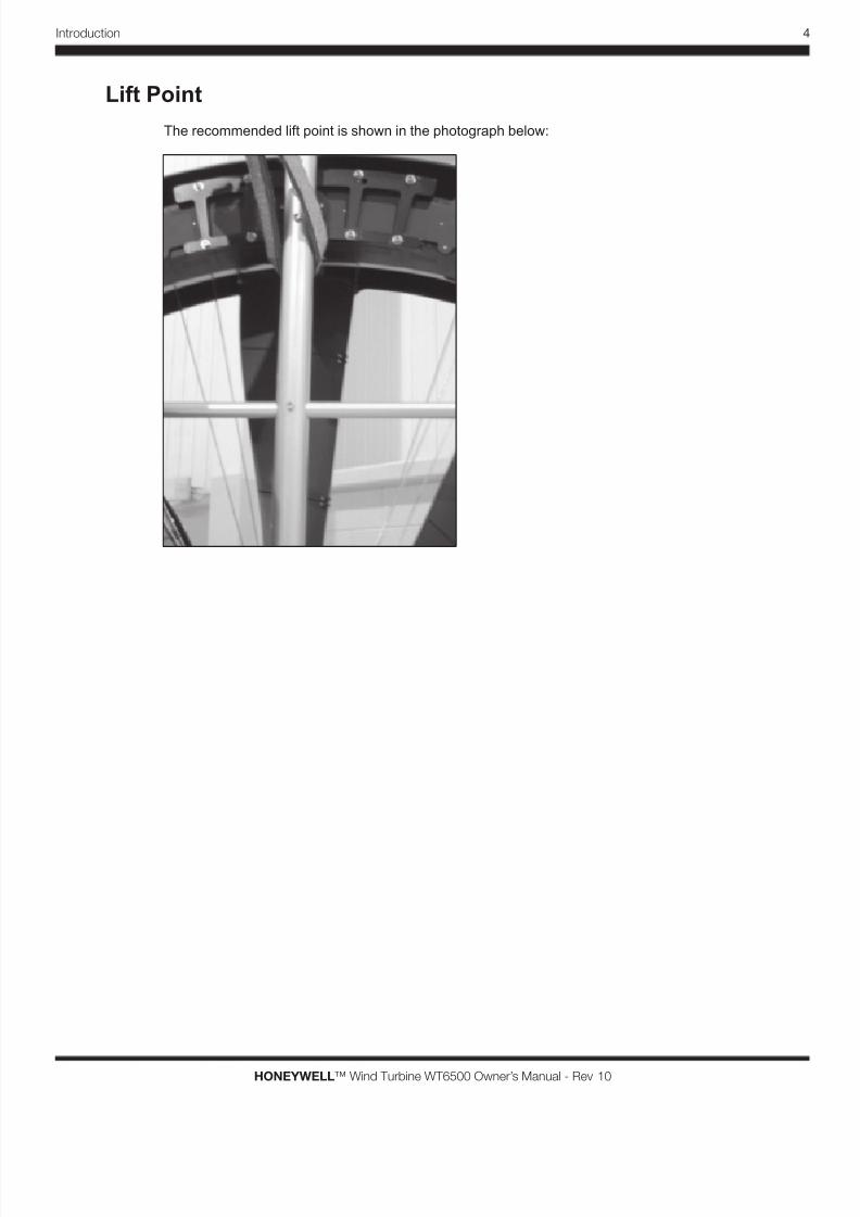
Lift Point
The recommended lift point is shown in the photograph below:
8/3/2019 Gearless Wind Generator Owner's Manual
http://slidepdf.com/reader/full/gearless-wind-generator-owners-manual 12/46
5 Turbine Installation
HONEYWELL™ Wind Turbine WT6500 Owner’s Manual - Rev 10
Turbine Mounting and
Wiring
Chapter 2 describes turbine installation, mounting options and
electrical wiring.
For Information on: See:
Introduction6
Site Selection 8
Mounting Options 10
Turbine Wiring 12
SMARTBOX™ Controller 14
Battery Box 15
Junction Box 16
Turbine Wiring Overview 18
Grounding 22
Operation 23
2
8/3/2019 Gearless Wind Generator Owner's Manual
http://slidepdf.com/reader/full/gearless-wind-generator-owners-manual 13/46
6
HONEYWELL™ Wind Turbine WT6500 Owner’s Manual - Rev 10
Turbine Installation
Turbine Mounting
Introduction
Hazardous voltages, currents, or other conditions that couldcause serious bodily injury or death exist in this equipment
or may be associated with its use.
Personal Injury and Property Damage Hazard
STOP! If you plan to connect the HONEYWELL™ Wind
Turbine to any controller other than the SMARTBOX™
Controller, immediately cease the installation of the
HONEYWELL™ Wind Turbine. The HONEYWELL™
Wind Turbine can only be connected to the SMARTBOX™
Controller or other controller pre-approved, in writing, by
WindTronics. Failure to follow this warning will void the
HONEYWELL™ Wind Turbine warranty and may resultin death, personal injury or property damage (including
damage to the HONEYWELL™ Wind Turbine).
PROFESSIONAL INSTALLATION required
After following the unpacking procedures included in the wind turbine package, it
is required that only licensed and trained personnel perform the installation and
maintenance of the wind turbine.
In general the installation consists of mounting the turbine on suitable and approvedmounting hardware. The installation procedure include recommendations for the
mounting options. They must be approved and certied by your local Professional
Engineer (PE) and a licensed and trained installer must acquire all the necessary
permits from the local authorities prior to installation.
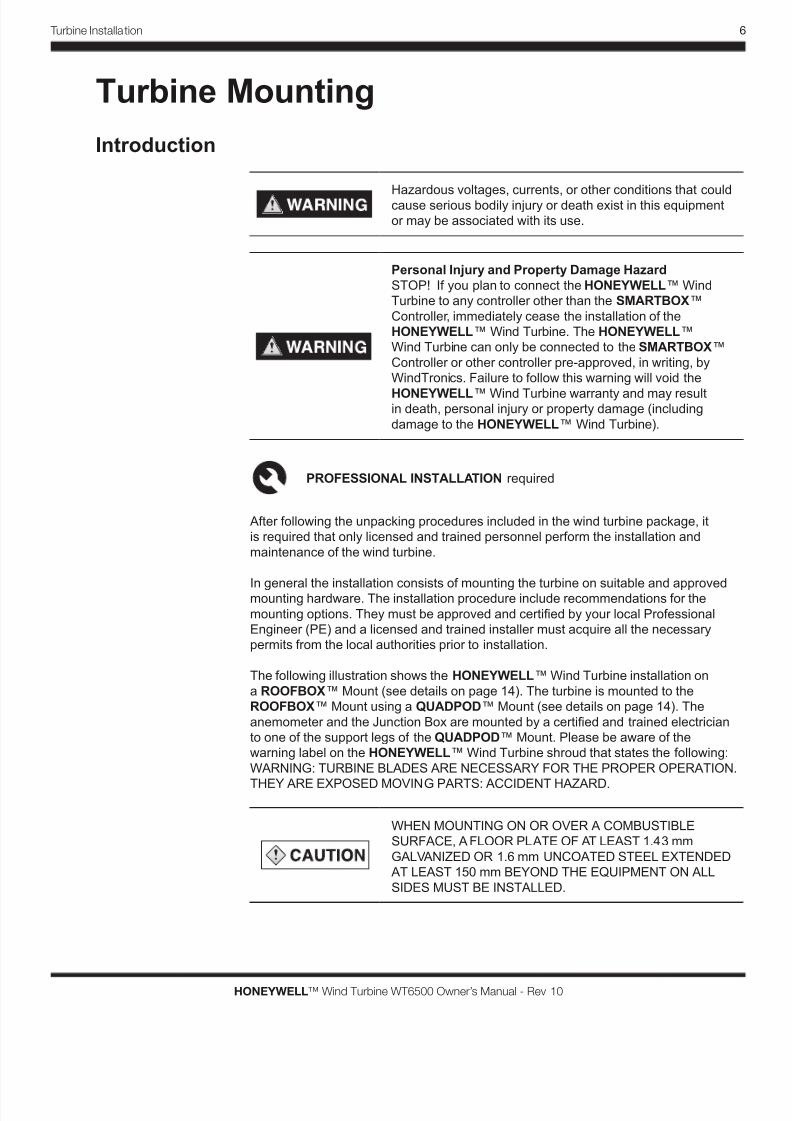
The following illustration shows the HONEYWELL™ Wind Turbine installation on
a ROOFBOX™ Mount (see details on page 14). The turbine is mounted to the
ROOFBOX™ Mount using a QUADPOD™ Mount (see details on page 14). The
anemometer and the Junction Box are mounted by a certied and trained electrician
to one of the support legs of the QUADPOD™ Mount. Please be aware of the
warning label on the HONEYWELL™ Wind Turbine shroud that states the following:
WARNING: TURBINE BLADES ARE NECESSARY FOR THE PROPER OPERATION.
THEY ARE EXPOSED MOVING PARTS: ACCIDENT HAZARD.
WHEN MOUNTING ON OR OVER A COMBUSTIBLE
SURFACE, A FLOOR PLATE OF AT LEAST 1.43 mm
GALVANIZED OR 1.6 mm UNCOATED STEEL EXTENDED
AT LEAST 150 mm BEYOND THE EQUIPMENT ON ALL
SIDES MUST BE INSTALLED.
8/3/2019 Gearless Wind Generator Owner's Manual
http://slidepdf.com/reader/full/gearless-wind-generator-owners-manual 14/46
7 Turbine Installation
HONEYWELL™ Wind Turbine WT6500 Owner’s Manual - Rev 10
Personal Injury and Property Damage Hazard
Do not touch revolving turbine blades or insert objects,
including sticks and screwdrivers, into revolving turbine
blades. Failure to follow this warning may result in death,
personal injury or property damage.
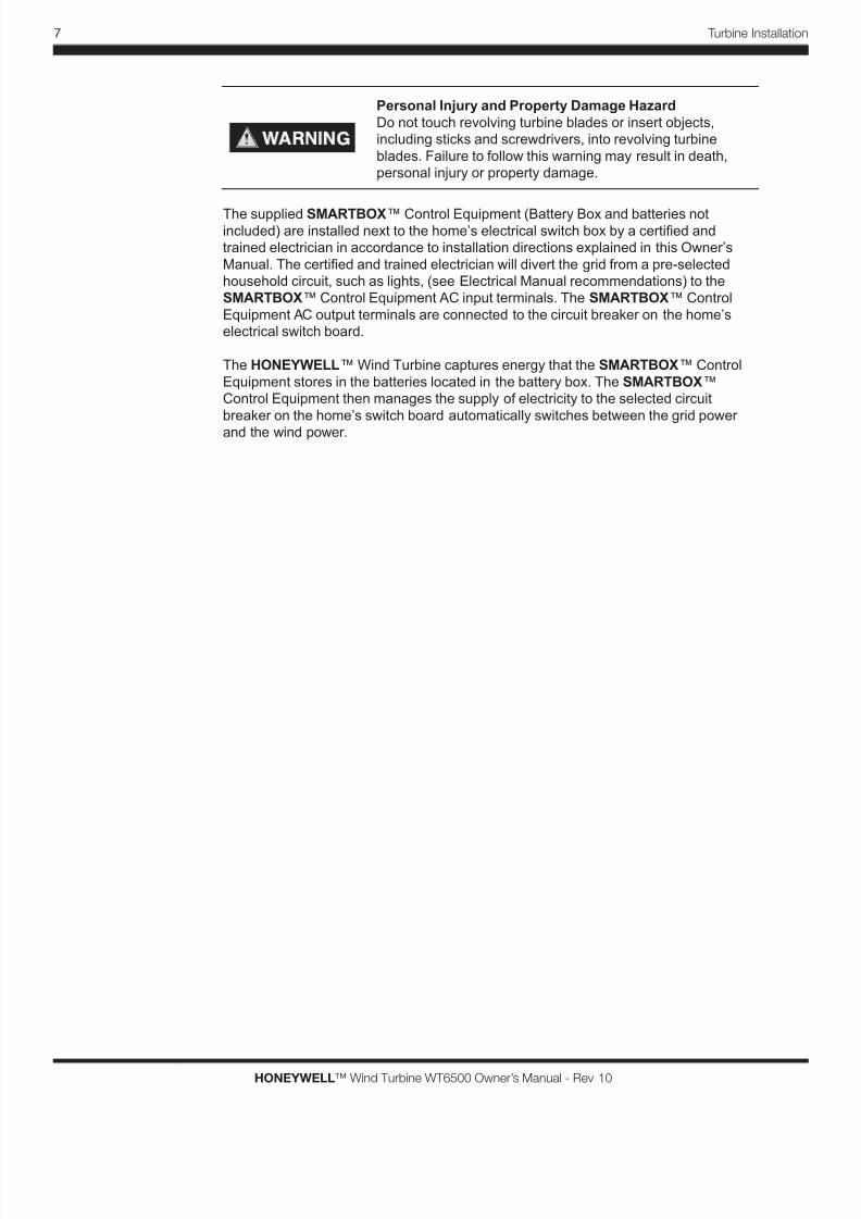
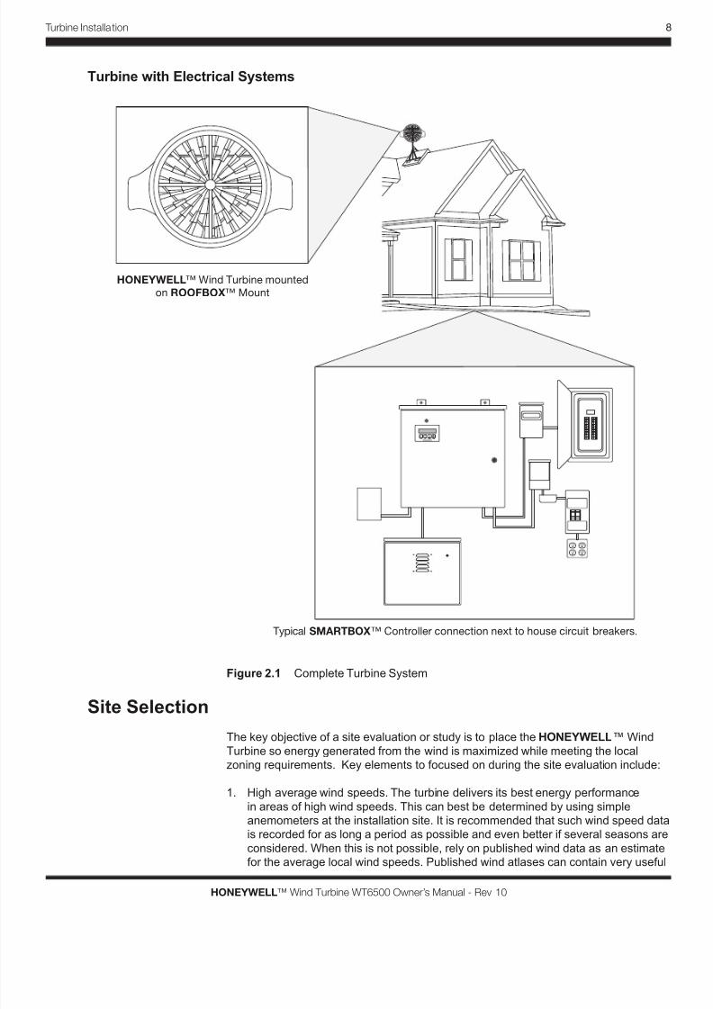
The supplied SMARTBOX™ Control Equipment (Battery Box and batteries notincluded) are installed next to the home’s electrical switch box by a certied and
trained electrician in accordance to installation directions explained in this Owner’s
Manual. The certied and trained electrician will divert the grid from a pre-selected
household circuit, such as lights, (see Electrical Manual recommendations) to the
SMARTBOX™ Control Equipment AC input terminals. The SMARTBOX™ Control
Equipment AC output terminals are connected to the circuit breaker on the home’s
electrical switch board.
The HONEYWELL™ Wind Turbine captures energy that the SMARTBOX™ Control
Equipment stores in the batteries located in the battery box. The SMARTBOX™
Control Equipment then manages the supply of electricity to the selected circuit
breaker on the home’s switch board automatically switches between the grid power
and the wind power.
8/3/2019 Gearless Wind Generator Owner's Manual
http://slidepdf.com/reader/full/gearless-wind-generator-owners-manual 15/46
8
HONEYWELL™ Wind Turbine WT6500 Owner’s Manual - Rev 10
Turbine Installation
Turbine with Electrical Systems
HONEYWELL™ Wind Turbine mounted
on ROOFBOX™ Mount
Typical SMARTBOX™ Controller connection next to house circuit breakers.
Figure 2.1 Complete Turbine System
Site SelectionThe key objective of a site evaluation or study is to place the HONEYWELL™ Wind
Turbine so energy generated from the wind is maximized while meeting the local
zoning requirements. Key elements to focused on during the site evaluation include:
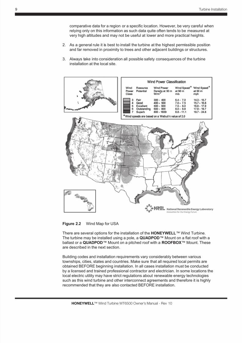
1. High average wind speeds. The turbine delivers its best energy performance
in areas of high wind speeds. This can best be determined by using simple
anemometers at the installation site. It is recommended that such wind speed data
is recorded for as long a period as possible and even better if several seasons are
considered. When this is not possible, rely on published wind data as an estimate
for the average local wind speeds. Published wind atlases can contain very useful
8/3/2019 Gearless Wind Generator Owner's Manual
http://slidepdf.com/reader/full/gearless-wind-generator-owners-manual 16/46
9 Turbine Installation
HONEYWELL™ Wind Turbine WT6500 Owner’s Manual - Rev 10
comparative data for a region or a specic location. However, be very careful when
relying only on this information as such data quite often tends to be measured at
very high altitudes and may not be useful at lower and more practical heights.
2. As a general rule it is best to install the turbine at the highest permissible position
and far removed in proximity to trees and other adjacent buildings or structures.
3. Always take into consideration all possible safety consequences of the turbineinstallation at the local site.
Figure 2.2 Wind Map for USA
There are several options for the installation of the HONEYWELL™ Wind Turbine.
The turbine may be installed using a pole, a QUADPOD™ Mount on a at roof with a
ballast or a QUADPOD™ Mount on a pitched roof with a ROOFBOX™ Mount. These
are described in the next section.
Building codes and installation requirements vary considerably between various
townships, cities, states and countries. Make sure that all required local permits are
obtained BEFORE beginning installation. In all cases installation must be conducted
by a licensed and trained professional contractor and electrician. In some locations the
local electric utility may have strict regulations about renewable energy technologies
such as this wind turbine and other interconnect agreements and therefore it is highly
recommended that they are also contacted BEFORE installation.
8/3/2019 Gearless Wind Generator Owner's Manual
http://slidepdf.com/reader/full/gearless-wind-generator-owners-manual 17/46
10
HONEYWELL™ Wind Turbine WT6500 Owner’s Manual - Rev 10
Turbine Installation
Mounting Options
Personal Injury and Property Damage Hazard
Do not install the HONEYWELL™ Wind Turbine in a
location that is accessible to children or pets. Failure to
follow this warning may result in death, personal injury or
property damage.
Personal Injury and Property Damage Hazard
The HONEYWELL™ Wind Turbine must be mounted by
licensed and trained personnel only, with the use of all
appropriate hardware. Failure to follow this warning will void
the HONEYWELL™ Wind Turbine warranty and may result
in death, personal injury or property damage (including
damage to the HONEYWELL™ Wind Turbine).
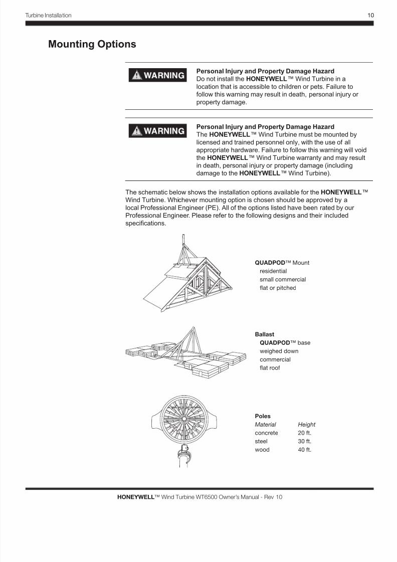
The schematic below shows the installation options available for the HONEYWELL™
Wind Turbine. Whichever mounting option is chosen should be approved by a
local Professional Engineer (PE). All of the options listed have been rated by our
Professional Engineer. Please refer to the following designs and their included
specications.
QUADPOD™ Mount
residential
small commercial
at or pitched
Ballast
QUADPOD™ base
weighed down
commercial
at roof
Poles
Material
concrete
steel
wood
Height
20 ft.
30 ft.
40 ft.
8/3/2019 Gearless Wind Generator Owner's Manual
http://slidepdf.com/reader/full/gearless-wind-generator-owners-manual 18/46
11 Turbine Installation
HONEYWELL™ Wind Turbine WT6500 Owner’s Manual - Rev 10
Figure 2.3 Mounting Options
Failure to follow proper installation practices for any of the
mounting options could result in death, personal injury and/
or property damage.
The vertical axis of the turbine must be level when installed.
Turbines installed with their vertical axis off-level will see
signicant impact on performance.
IMPORTANT: The ROOFBOX™ QUADPOD™ system is designed for
pitched or at roof tops. As roof construction and roof lines vary, pole mounted
installations are recommended for residential environments for optimal cost,
exibility and performance.
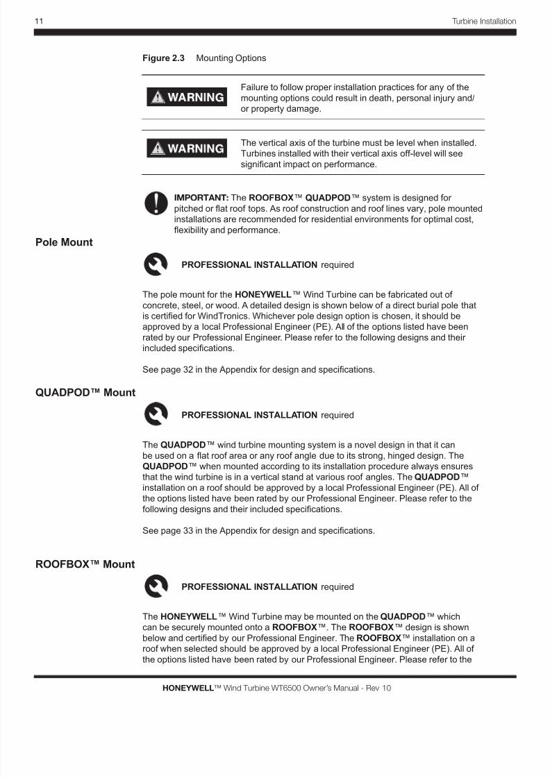
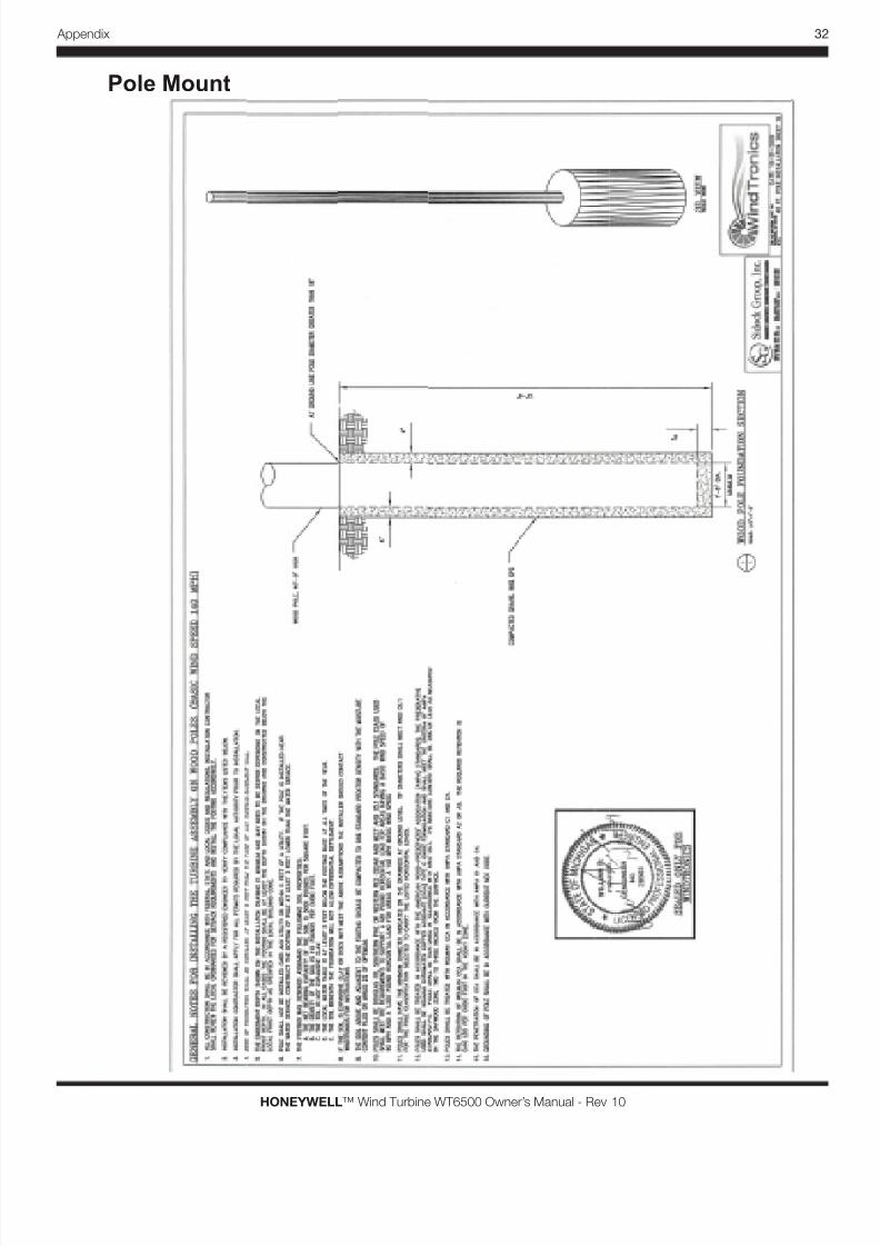
Pole Mount
PROFESSIONAL INSTALLATION required
The pole mount for the HONEYWELL™ Wind Turbine can be fabricated out of
concrete, steel, or wood. A detailed design is shown below of a direct burial pole that
is certied for WindTronics. Whichever pole design option is chosen, it should be
approved by a local Professional Engineer (PE). All of the options listed have been
rated by our Professional Engineer. Please refer to the following designs and their
included specications.
See page 32 in the Appendix for design and specications.
QUADPOD™ Mount
PROFESSIONAL INSTALLATION required
The QUADPOD™ wind turbine mounting system is a novel design in that it can
be used on a at roof area or any roof angle due to its strong, hinged design. The
QUADPOD™ when mounted according to its installation procedure always ensures
that the wind turbine is in a vertical stand at various roof angles. The QUADPOD™
installation on a roof should be approved by a local Professional Engineer (PE). All of
the options listed have been rated by our Professional Engineer. Please refer to the
following designs and their included specications.
See page 33 in the Appendix for design and specications.
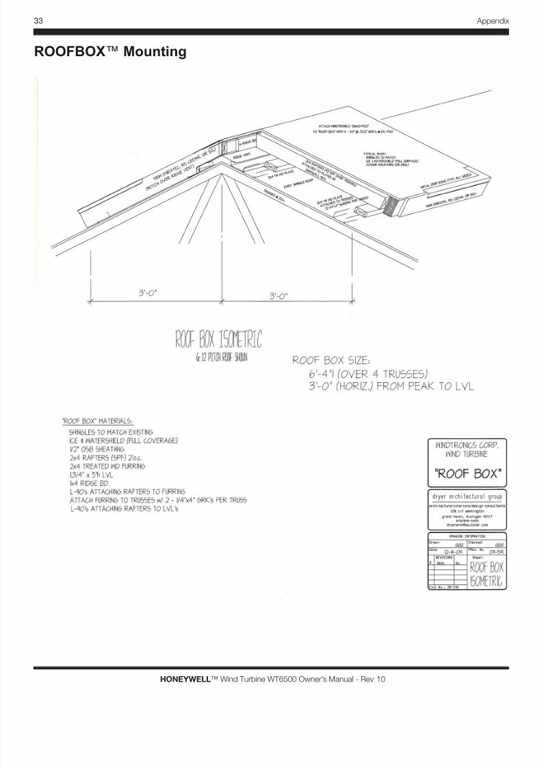
ROOFBOX™ Mount
PROFESSIONAL INSTALLATION required
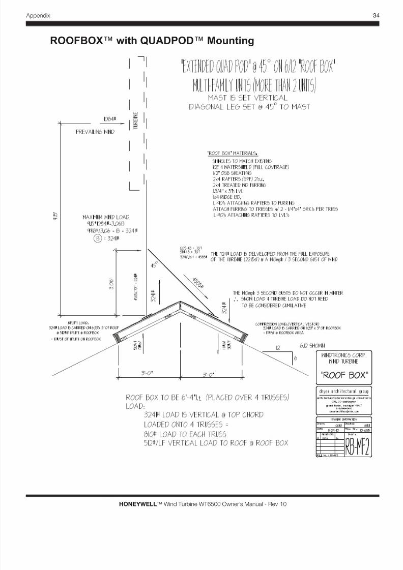
The HONEYWELL™ Wind Turbine may be mounted on the QUADPOD™ which
can be securely mounted onto a ROOFBOX™. The ROOFBOX™ design is shown
below and certied by our Professional Engineer. The ROOFBOX™ installation on a
roof when selected should be approved by a local Professional Engineer (PE). All of
the options listed have been rated by our Professional Engineer. Please refer to the
8/3/2019 Gearless Wind Generator Owner's Manual
http://slidepdf.com/reader/full/gearless-wind-generator-owners-manual 19/46
12
HONEYWELL™ Wind Turbine WT6500 Owner’s Manual - Rev 10
Turbine Installation
following designs and their included specications.
See page 34 in the Appendix for design and specications.
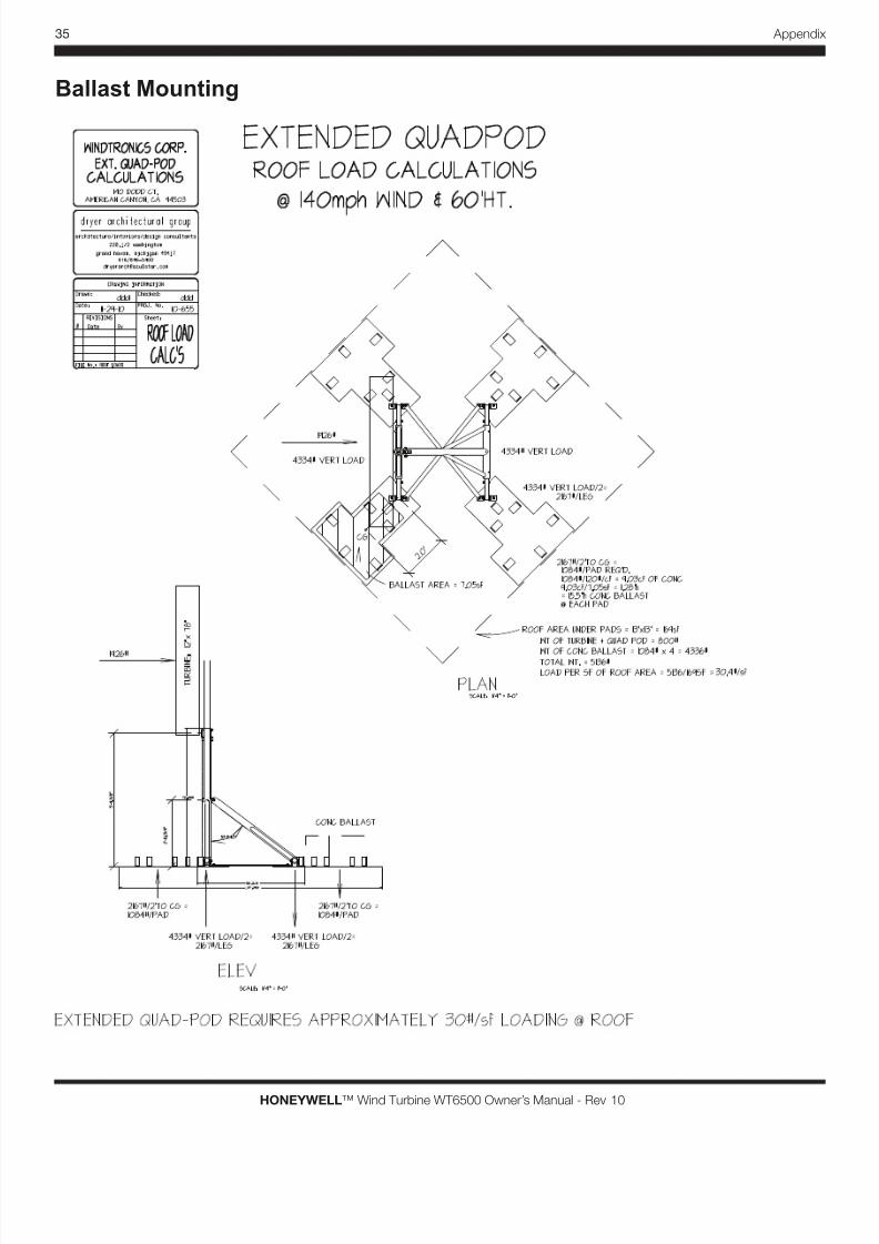
Ballast Mount
See page 35 in the Appendix for design and specications.
Turbine Wiring
ELECTRIC SHOCK HAZARD
Disconnect turbine and battery circuits before wiring.
Turn off all power before wiring. Failure to follow safety
warning could result in serious injury and/or death.
Personal Injury and Property Damage Hazard
STOP! If you plan to connect the HONEYWELL™ WindTurbine to any controller other than the SMARTBOX™
Controller, immediately cease the installation of the
HONEYWELL™ Wind Turbine. Failure to follow this
warning will void the HONEYWELL™ Wind Turbine
warranty and may result in death, personal injury or
property damage (including damage to the HONEYWELL™
Wind Turbine).
PROFESSIONAL INSTALLATION required
Installations must meet all local electrical codes. Installations for the equipment should
only be performed by a qualied electrician or a licensed and trained WindTronics
installer.
The wiring connections between a mounted HONEYWELL™ Wind Turbine, Battery
Box and SMARTBOX™ Controller is relatively simple. The following diagram details
and species the wire gauges required in this installation. It is strongly recommended
that a certied and trained electrician performs all the electrical connection. All
electrical systems must be grounded in accordance to the National Electric Code
(NEC) (or, in Canada, the Canadian Electric Code (CEC)) and local standards. Please
refer to the SMARTBOX™ Controller Manual for full details on wiring, connecting and
commissioning of the HONEYWELL™ Wind Turbine.
8/3/2019 Gearless Wind Generator Owner's Manual
http://slidepdf.com/reader/full/gearless-wind-generator-owners-manual 20/46
13 Turbine Installation
HONEYWELL™ Wind Turbine WT6500 Owner’s Manual - Rev 10
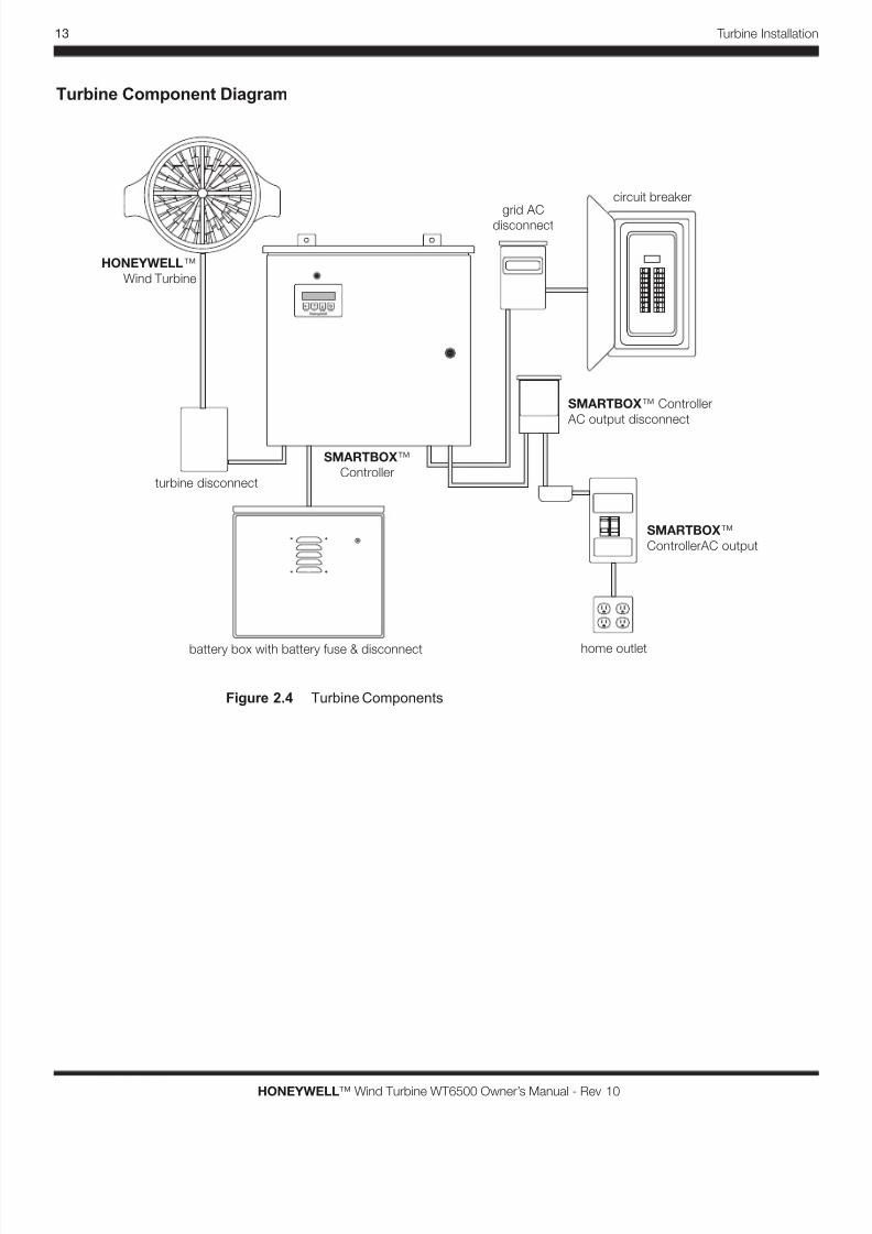
Turbine Component Diagram
turbine disconnect
home outlet
SMARTBOX™ Controller
AC output disconnect
circuit breaker
battery box with battery fuse & disconnect
SMARTBOX™
Controller
HONEYWELL™
Wind Turbine
SMARTBOX™
ControllerAC output
grid ACdisconnect
Figure 2.4 Turbine Components
8/3/2019 Gearless Wind Generator Owner's Manual
http://slidepdf.com/reader/full/gearless-wind-generator-owners-manual 21/46
14
HONEYWELL™ Wind Turbine WT6500 Owner’s Manual - Rev 10
Turbine Installation
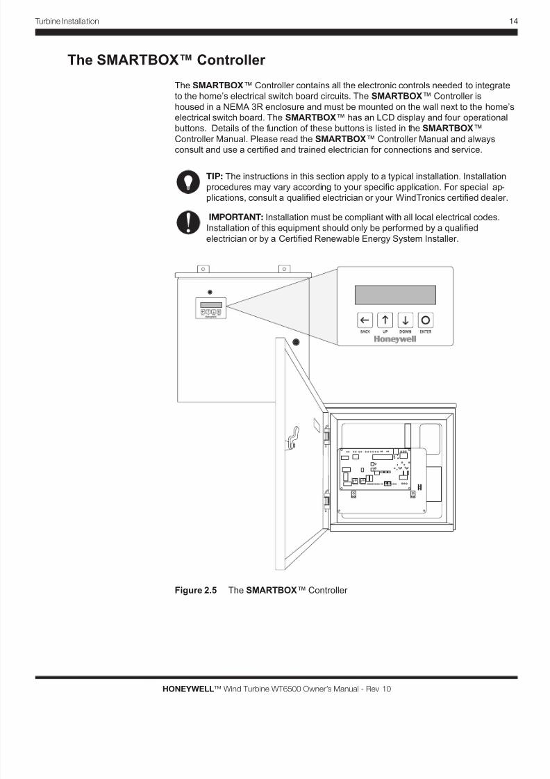
The SMARTBOX™ Controller
The SMARTBOX™ Controller contains all the electronic controls needed to integrate
to the home’s electrical switch board circuits. The SMARTBOX™ Controller is
housed in a NEMA 3R enclosure and must be mounted on the wall next to the home’s
electrical switch board. The SMARTBOX™ has an LCD display and four operational
buttons. Details of the function of these buttons is listed in the SMARTBOX™
Controller Manual. Please read the SMARTBOX™ Controller Manual and alwaysconsult and use a certied and trained electrician for connections and service.
TIP: The instructions in this section apply to a typical installation. Installation
procedures may vary according to your specic application. For special ap-
plications, consult a qualied electrician or your WindTronics certied dealer.
IMPORTANT: Installation must be compliant with all local electrical codes.
Installation of this equipment should only be performed by a qualied
electrician or by a Certied Renewable Energy System Installer.
Figure 2.5 The SMARTBOX™ Controller
8/3/2019 Gearless Wind Generator Owner's Manual
http://slidepdf.com/reader/full/gearless-wind-generator-owners-manual 22/46
15 Turbine Installation
HONEYWELL™ Wind Turbine WT6500 Owner’s Manual - Rev 10
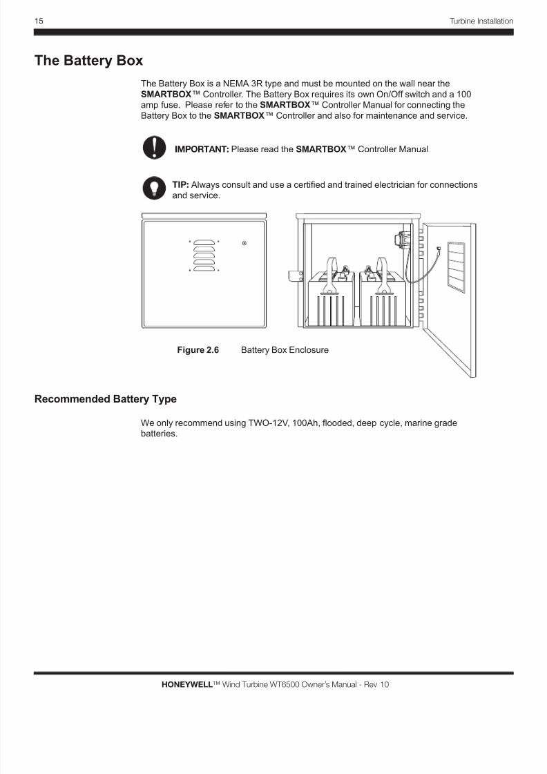
The Battery Box
The Battery Box is a NEMA 3R type and must be mounted on the wall near the
SMARTBOX™ Controller. The Battery Box requires its own On/Off switch and a 100
amp fuse. Please refer to the SMARTBOX™ Controller Manual for connecting the
Battery Box to the SMARTBOX™ Controller and also for maintenance and service.
IMPORTANT: Please read the SMARTBOX™ Controller Manual
TIP: Always consult and use a certied and trained electrician for connections
and service.
Recommended Battery Type
We only recommend using TWO-12V, 100Ah, ooded, deep cycle, marine grade
batteries.
Figure 2.6 Battery Box Enclosure
8/3/2019 Gearless Wind Generator Owner's Manual
http://slidepdf.com/reader/full/gearless-wind-generator-owners-manual 23/46
16
HONEYWELL™ Wind Turbine WT6500 Owner’s Manual - Rev 10
Turbine Installation
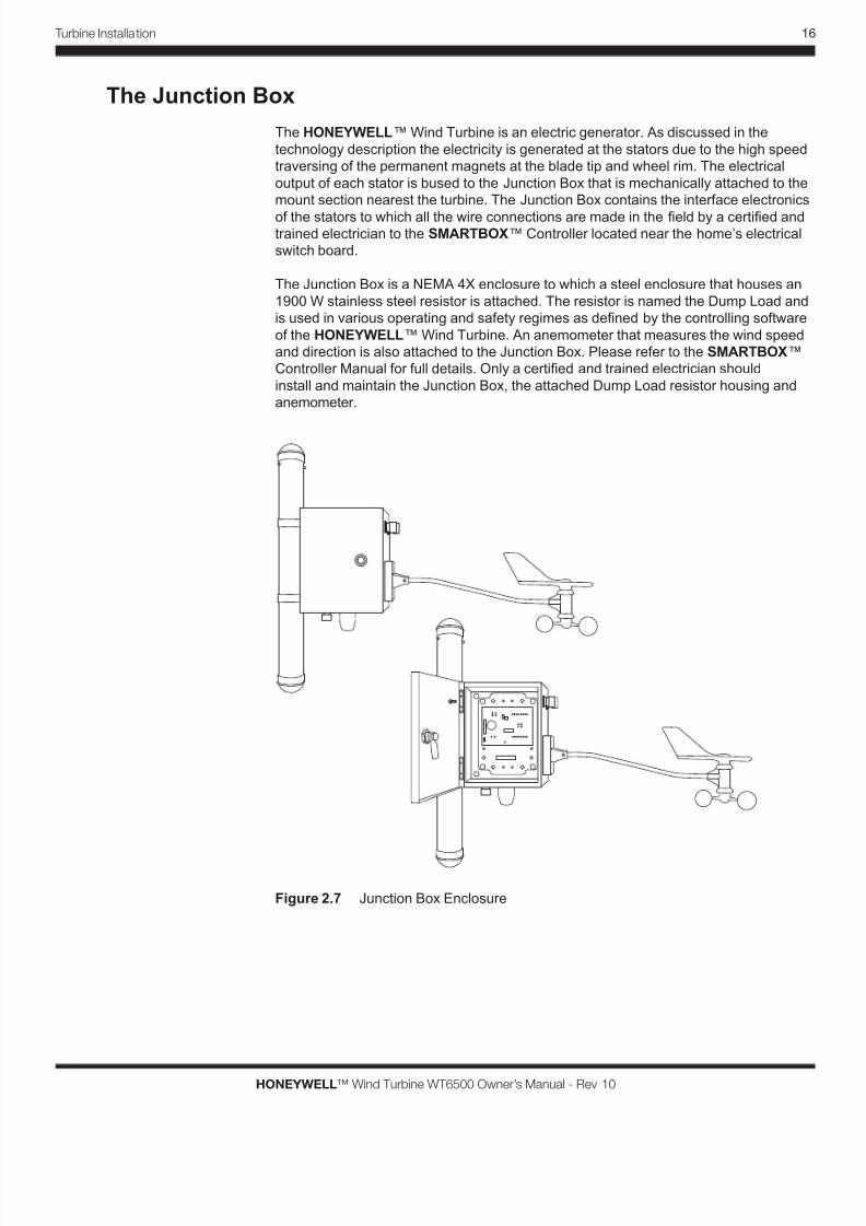
The Junction Box
The HONEYWELL™ Wind Turbine is an electric generator. As discussed in the
technology description the electricity is generated at the stators due to the high speed
traversing of the permanent magnets at the blade tip and wheel rim. The electrical
output of each stator is bused to the Junction Box that is mechanically attached to the
mount section nearest the turbine. The Junction Box contains the interface electronics
of the stators to which all the wire connections are made in the eld by a certied andtrained electrician to the SMARTBOX™ Controller located near the home’s electrical
switch board.
The Junction Box is a NEMA 4X enclosure to which a steel enclosure that houses an
1900 W stainless steel resistor is attached. The resistor is named the Dump Load and
is used in various operating and safety regimes as dened by the controlling software
of the HONEYWELL™ Wind Turbine. An anemometer that measures the wind speed
and direction is also attached to the Junction Box. Please refer to the SMARTBOX™
Controller Manual for full details. Only a certied and trained electrician should
install and maintain the Junction Box, the attached Dump Load resistor housing and
anemometer.
Figure 2.7 Junction Box Enclosure
8/3/2019 Gearless Wind Generator Owner's Manual
http://slidepdf.com/reader/full/gearless-wind-generator-owners-manual 24/46
17 Turbine Installation
HONEYWELL™ Wind Turbine WT6500 Owner’s Manual - Rev 10
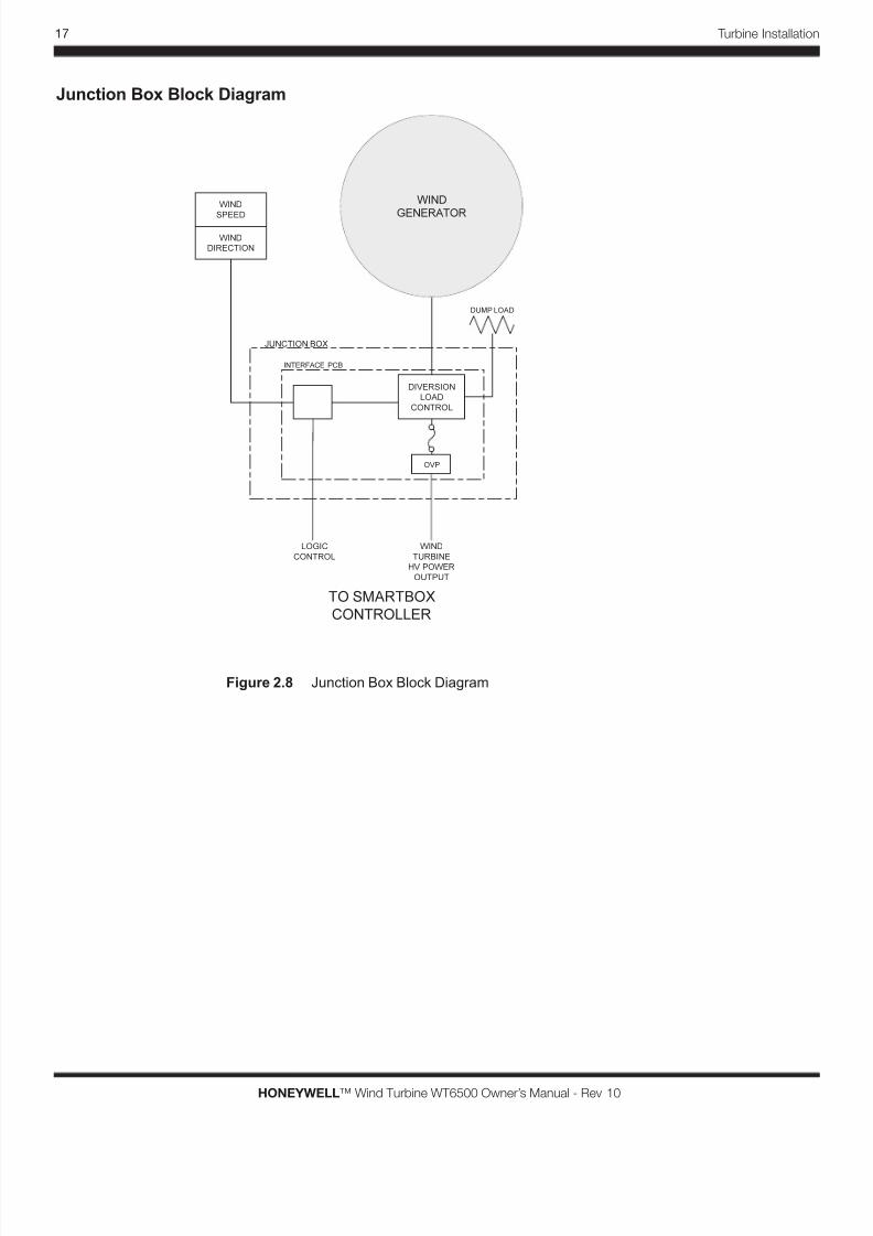
Junction Box Block Diagram
WIND
GENERATOR
TO SMARTBOX
CONTROLLER
DIVERSION
LOAD
CONTROL
WIND
DIRECTION
WIND
SPEED
OVP
JUNCTION BOX
WIND
TURBINE
HV POWER
OUTPUT
LOGIC
CONTROL
INTERFACE PCB
DUMP LOAD
Figure 2.8 Junction Box Block Diagram
8/3/2019 Gearless Wind Generator Owner's Manual
http://slidepdf.com/reader/full/gearless-wind-generator-owners-manual 25/46
18
HONEYWELL™ Wind Turbine WT6500 Owner’s Manual - Rev 10
Turbine Installation
T U R B I N E J U N C T I O N B O X
E A R T H
G R O U N D
S T A K E
A C
I N
T U R B I N E S M A R T B O X ™ C o n t r o l l e r
1 2 V
1 2 V
1 2 V
1 2 V
1 2 V
1 2 V
O P T I O N A L
T U R B I N E P O L E S
L 1
N
G N D
A C O U T P U T
T O S U B S W I T C H
B O A R D
S I N G L E P H A S E
1 2 0 V 1 5 A M P
L 1
N
G N D
A C I N P U T
F R O M M A I N S W I T C H
B O A R D
S I N G L E P H A S E
1 2 0 V 1 5 A M P
S E E T U R B I N E T O C O N T R O L L E R S I Z E
C H A R T O N S H E E T 1
( 2 ) # 1 0 T H W N - 2 + # 6 G N D
¾ ” C O N D U I T
M A X D I S T A N C E 3 F E E T .
( 2 ) # 4 T H W N - 2 + # 4 G N D
1 ” C O N D U I T
M A X D I S T A N C E 6 F E E T .
( 2 ) # 1 2 T H W N - 2
+ # 6 G N D
¾ ” C O N D U
I T
( 2 ) # 1 2 T H W N - 2
+ # 6 G N D
¾ ” C O N D U I T
C A T 5 E
o r C A T 6
G R N / W H T
G R N
B R N / W H T
B R N
B L U / W H T
B L U
O R G / W H T
O R G
G R N / W H T
G R N
B R N / W H T
B R N
B L U / W H T
B L U
O R G / W H T
O R G
# 4 G N D
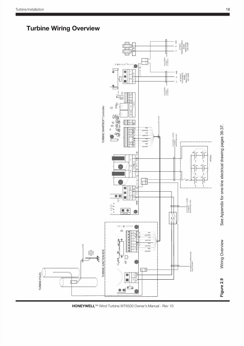
F i g u r e
2 .
9
W i r i n g O v e r v i e w
S e e A p p e n d i x f o r o n e - l i n e
e l e c t r i c a l d r a w i n g p a g e s 3 6 - 3 7 .
Turbine Wiring Overview
8/3/2019 Gearless Wind Generator Owner's Manual
http://slidepdf.com/reader/full/gearless-wind-generator-owners-manual 26/46
19 Turbine Installation
HONEYWELL™ Wind Turbine WT6500 Owner’s Manual - Rev 10
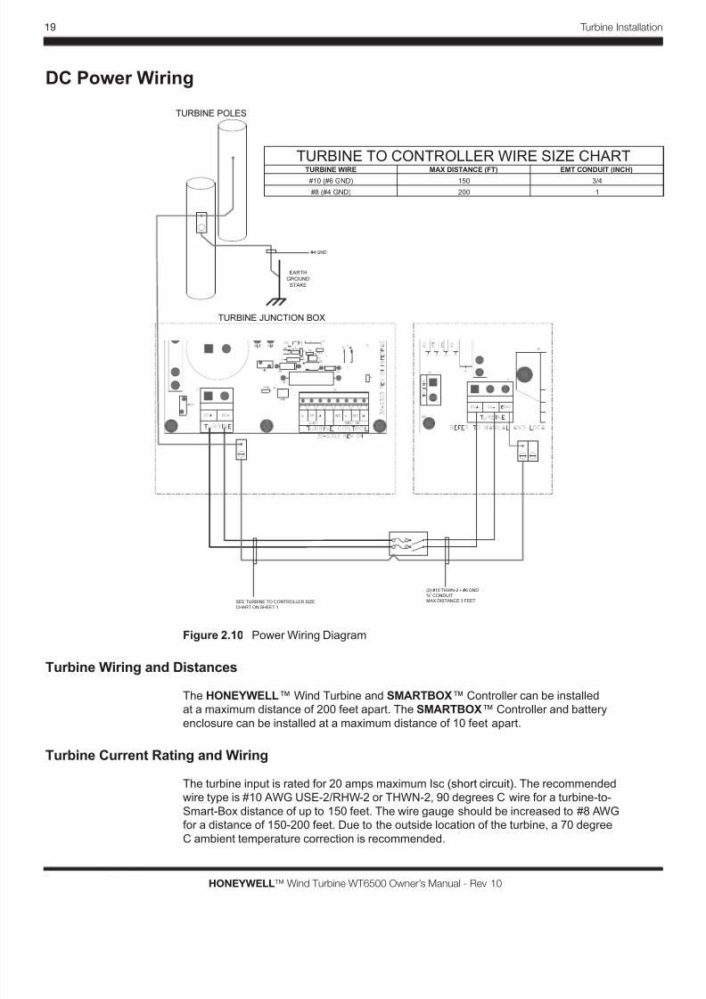
DC Power Wiring
TURBINE JUNCTION BOX
EARTH
GROUND
STAKE
TURBINE POLES
SEE TURBINE TO CONTROLLER SIZE
CHART ON SHEET 1
(2) #10 THWN-2 + #6 GND
¾” CONDUIT
MAX DISTANCE 3 FEET.
#4 GND
Figure 2.10 Power Wiring Diagram
Turbine Wiring and Distances
The HONEYWELL™ Wind Turbine and SMARTBOX™ Controller can be installedat a maximum distance of 200 feet apart. The SMARTBOX™ Controller and battery
enclosure can be installed at a maximum distance of 10 feet apart.
Turbine Current Rating and Wiring
The turbine input is rated for 20 amps maximum Isc (short circuit). The recommended
wire type is #10 AWG USE-2/RHW-2 or THWN-2, 90 degrees C wire for a turbine-to-
Smart-Box distance of up to 150 feet. The wire gauge should be increased to #8 AWG
for a distance of 150-200 feet. Due to the outside location of the turbine, a 70 degree
C ambient temperature correction is recommended.
TURBINE TO CONTROLLER WIRE SIZE CHARTTURBINE WIRE MAX DISTANCE (FT) EMT CONDUIT (INCH)
#10 (#6 GND) 3/4
#8 (#4 GND) 1
150
200
8/3/2019 Gearless Wind Generator Owner's Manual
http://slidepdf.com/reader/full/gearless-wind-generator-owners-manual 27/46
20
HONEYWELL™ Wind Turbine WT6500 Owner’s Manual - Rev 10
Turbine Installation
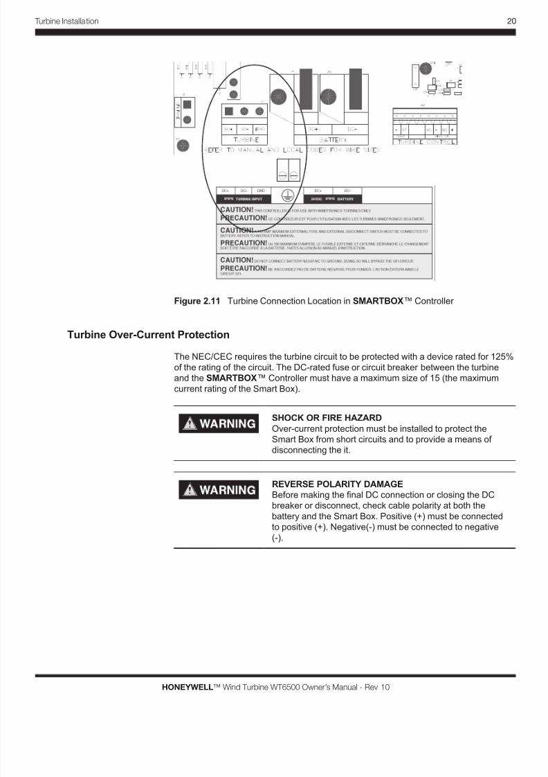
Figure 2.11 Turbine Connection Location in SMARTBOX™ Controller
Turbine Over-Current Protection
The NEC/CEC requires the turbine circuit to be protected with a device rated for 125%
of the rating of the circuit. The DC-rated fuse or circuit breaker between the turbine
and the SMARTBOX™ Controller must have a maximum size of 15 (the maximum
current rating of the Smart Box).
SHOCK OR FIRE HAZARD
Over-current protection must be installed to protect the
Smart Box from short circuits and to provide a means of
disconnecting the it.
REVERSE POLARITY DAMAGE
Before making the nal DC connection or closing the DC
breaker or disconnect, check cable polarity at both the
battery and the Smart Box. Positive (+) must be connected
to positive (+). Negative(-) must be connected to negative
(-).
8/3/2019 Gearless Wind Generator Owner's Manual
http://slidepdf.com/reader/full/gearless-wind-generator-owners-manual 28/46
21 Turbine Installation
HONEYWELL™ Wind Turbine WT6500 Owner’s Manual - Rev 10
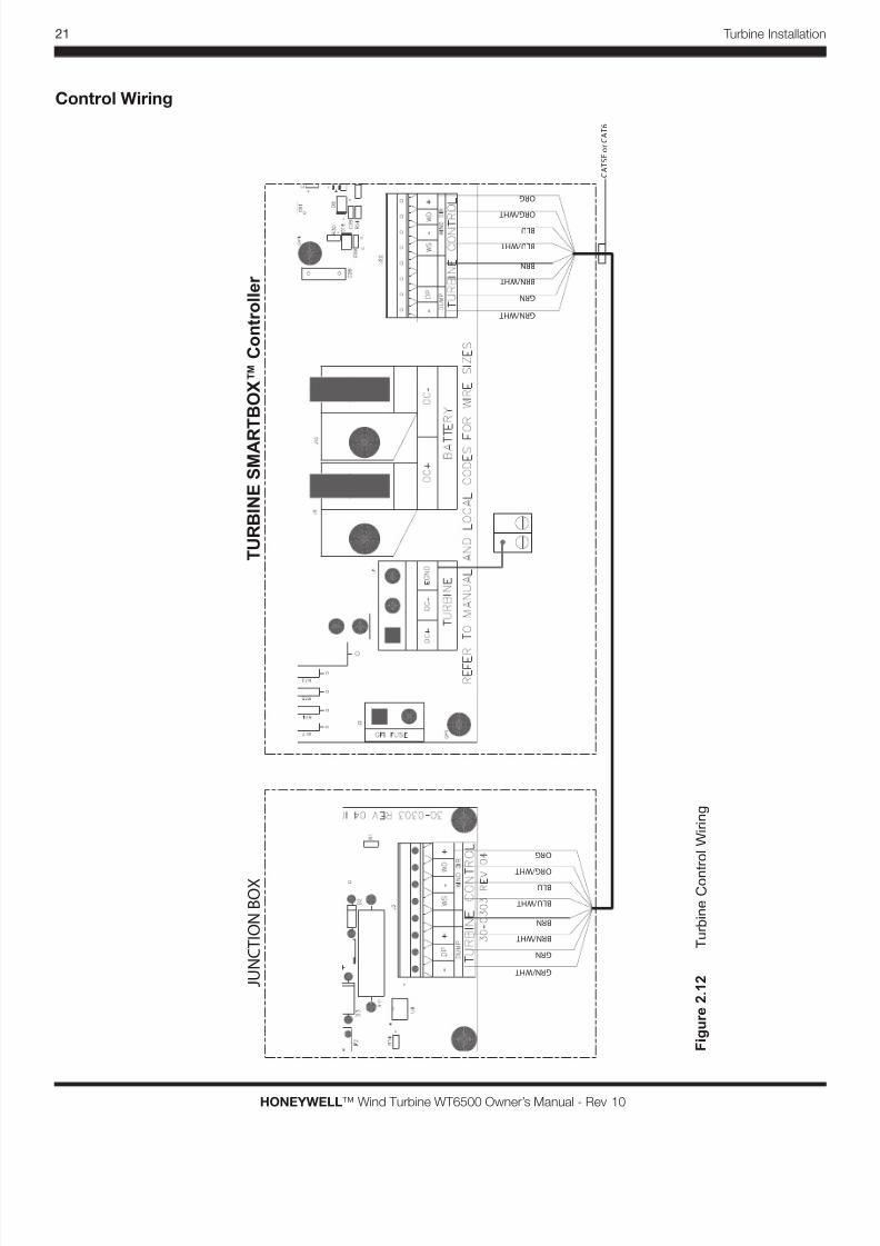
Control Wiring
J U N C T I O N
B O X
T U R B I N E S M A R
T B O X ™ C o n t r o l l e r
C A T 5 E o r C A T 6
G R N / W H T
G R N
B R N / W H T
B R N
B L U / W H T
B L U
O R G / W H T
O R G
G R N / W H T
G R N
B R N / W H T
B R N
B L U / W H T
B L U
O R G / W H T
O R G
F i g u r e
2 .
1 2
T u r b i n e C o n t r o l W i r i n g
8/3/2019 Gearless Wind Generator Owner's Manual
http://slidepdf.com/reader/full/gearless-wind-generator-owners-manual 29/46
22
HONEYWELL™ Wind Turbine WT6500 Owner’s Manual - Rev 10
Turbine Installation
Grounding
PROFESSIONAL INSTALLATION A certied and trained electrician must
install and commission this turbine using the National Electric Code (NEC)
(or, if in Canada, the Canadian Electric Code (CEC)) and in compliance to the
local permitting and zoning codes.
The SMARTBOX™ Controller is designed to work only with the HONEYWELL™
Wind Turbine. The turbine uses a negative-grounded electrical system. Grounding for
the turbine, battery and AC circuits are provided inside the wiring compartment. Each
ground connection can accommodate up to #6 AWG wire size. GFI: A fuse rated at
.5A 250V, accessible from the bottom of the wiring compartment, grounds the negative
conductor of the turbine and provides turbine ground-fault protection. Only a Littelfuse
0312.500HXP or equivalent fuse should be used as a replacement.
SHOCK HAZARD
DO NOT connect the battery negative to ground. NEC
requirements specify that the battery negative ground must
be done only through the 1A fuse. Bonding the battery
negative to ground will disable the turbine’s ground fault
protection and will result in improper operation. The battery
compartment should be grounded if made of metal.
SHOCK AND FIRE HAZARD
Fuses must only be replaced by qualied service personnel,
such as a certied electrician or technician. For continued
protection again risk of re, replace only with the same type
and rating of fuse. Failure to follow this warning may result
in death, personal injury or property damage.
SHOCK HAZARD
Disconnect wind and battery circuits before removing the
grounding connections or before removing or installing the
fuse. Wait at least 5 minutes for the internal circuitry to dis-
charge before servicing the unit. Failure to follow this warn-
ing may result in death, personal injury or property damage.
Even though the wind turbine is grounded at the service manual, it must also be
grounded at the base of the mounting pole, QUADPOD™ Mount, or TriPod. Grounding
at these mounts may prevent electric shock and voltage surges. Proper mount
grounding may also minimize damage due to lightning strikes.
Grounding information is available from the National Electric Code (NEC) USA 2005
as well as the International Electrotechnical Commission (IEC) standard 60364-
5-54 section Erection of Electrical Equipment: Earthing Arrangements, Protective
Conductors and Protective Bonding Conductors. Please reference the NEC and IEC
standards regarding full details of grounding this wind turbine. Please also refer to
205 NEC article 250.53 (G) regarding the grounding electrode installation. Also refer
to 2005 NEC article 250.66 (A) regarding conductor size where it stipulates that where
a grounding electrode conductor is connected to a rod, pipe or plate electrode, that
portion of the conductor that is the sole connection to the grounding electrode shall be
a minimum of 6AWG copper wire or 4AWG aluminum wire.
8/3/2019 Gearless Wind Generator Owner's Manual
http://slidepdf.com/reader/full/gearless-wind-generator-owners-manual 30/46
23 Turbine Installation
HONEYWELL™ Wind Turbine WT6500 Owner’s Manual - Rev 10
Operation
Personal Injury and Property Damage Hazard
Do not touch revolving turbine blades or insert objects,
including sticks and screwdrivers, into revolving turbine
blades. Failure to follow this may result in death, personal
injury or property damage.
PROFESSIONAL INSTALLATION A certied and trained electrician must
install and commission this turbine using the National Electric Code (NEC)
(or, if in Canada, the Canadian Electric Code (CEC)) and in compliance to the
local permitting and zoning codes.
Follow the electrical connections and commissioning procedures in the SMARTBOX™
Controller Manual for the wind turbine start up, operations, and maintenance. The label
below is provided to indicate the location of the AC POWER disconnect switch. Please
cut out and place near the SMARTBOX™ Controller where an electrician and service
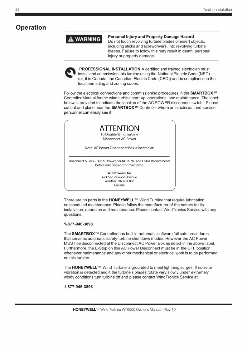
personnel can easily see it.
ATTENTION To Disable Wind Turbine
Disconnect AC Power
Note: AC Power Disconnect Box is located at:
Disconnect & Lock - Out AC Power per NFPA 70E and OSHA Requirements
before servicing and/or maintance.
Windtronics, Inc
621 Sprucewood Avenue
Windsor, ON N9C0B3
Canada
There are no parts in the HONEYWELL™ Wind Turbine that require lubrication
or scheduled maintenance. Please follow the manufacturer of the battery for its
installation, operation and maintenance. Please contact WindTronics Service with any
questions:
1-877-946-3898
The SMARTBOX™ Controller has built in automatic software fail safe procedures
that serve as automatic safety turbine shut down modes. However the AC Power
MUST be disconnected at the Disconnect AC Power Box as noted in the above label.Furthermore, the E-Stop on this AC Power Disconnect must be in the OFF position
whenever maintenance and any other mechanical or electrical work is to be performed
on this turbine.
The HONEYWELL™ Wind Turbine is grounded to meet lightning surges. If noise or
vibration is detected and if the turbine’s blades rotate very slowly under extremely
windy conditions turn turbine off and please contact WindTronics Service at:
1-877-946-3898

8/3/2019 Gearless Wind Generator Owner's Manual
http://slidepdf.com/reader/full/gearless-wind-generator-owners-manual 31/46
24
HONEYWELL™ Wind Turbine WT6500 Owner’s Manual - Rev 10
Turbine Installation
8/3/2019 Gearless Wind Generator Owner's Manual
http://slidepdf.com/reader/full/gearless-wind-generator-owners-manual 32/46
25 Specifcations
HONEYWELL™ Wind Turbine WT6500 Owner’s Manual - Rev 10
Specifcations
For Information on: See:
Technical Specication 25
3
8/3/2019 Gearless Wind Generator Owner's Manual
http://slidepdf.com/reader/full/gearless-wind-generator-owners-manual 33/46
26
HONEYWELL™ Wind Turbine WT6500 Owner’s Manual - Rev 10
Specifcations
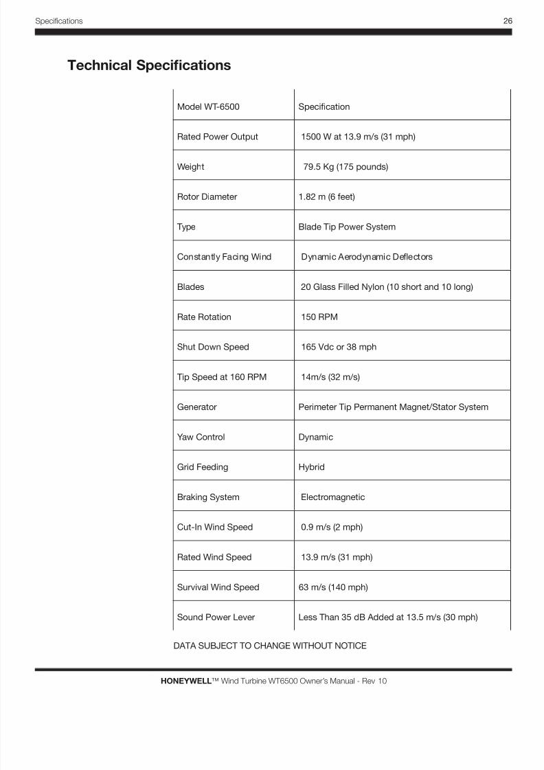
Technical Specifcations
Model WT-6500 Specication
Rated Power Output 1500 W at 13.9 m/s (31 mph)
Weight 79.5 Kg (175 pounds)
Rotor Diameter 1.82 m (6 feet)
Type Blade Tip Power System
Constantly Facing Wind Dynamic Aerodynamic Deectors
Blades 20 Glass Filled Nylon (10 short and 10 long)
Rate Rotation 150 RPM
Shut Down Speed 165 Vdc or 38 mph
Tip Speed at 160 RPM 14m/s (32 m/s)
Generator Perimeter Tip Permanent Magnet/Stator System
Yaw Control Dynamic
Grid Feeding Hybrid
Braking System Electromagnetic
Cut-In Wind Speed 0.9 m/s (2 mph)
Rated Wind Speed 13.9 m/s (31 mph)
Survival Wind Speed 63 m/s (140 mph)
Sound Power Lever Less Than 35 dB Added at 13.5 m/s (30 mph)
DATA SUBJECT TO CHANGE WITHOUT NOTICE

8/3/2019 Gearless Wind Generator Owner's Manual
http://slidepdf.com/reader/full/gearless-wind-generator-owners-manual 34/46
27
HONEYWELL™ Wind Turbine WT6500 Owner’s Manual - Rev 10
Warranty Information4
8/3/2019 Gearless Wind Generator Owner's Manual
http://slidepdf.com/reader/full/gearless-wind-generator-owners-manual 35/46
28
HONEYWELL™ Wind Turbine WT6500 Owner’s Manual - Rev 10
Warrantry
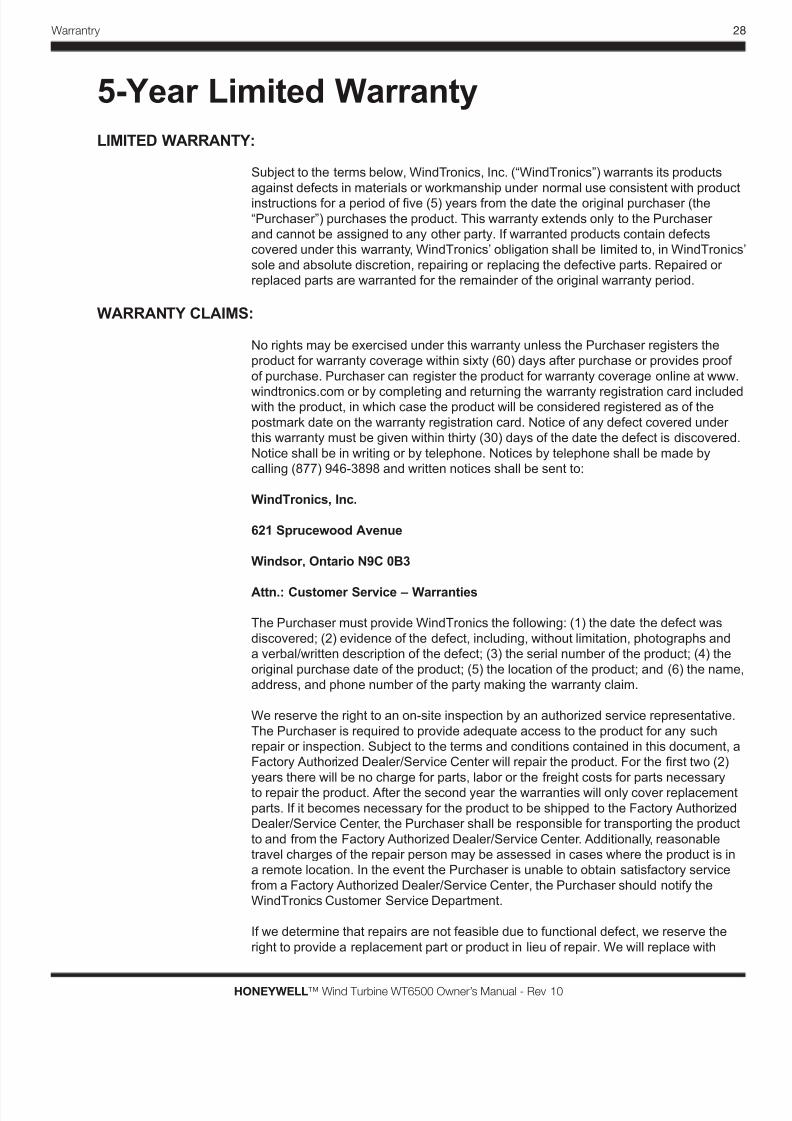
5-Year Limited Warranty
LIMITED WARRANTY:
Subject to the terms below, WindTronics, Inc. (“WindTronics”) warrants its products
against defects in materials or workmanship under normal use consistent with product
instructions for a period of ve (5) years from the date the original purchaser (the
“Purchaser”) purchases the product. This warranty extends only to the Purchaser
and cannot be assigned to any other party. If warranted products contain defects
covered under this warranty, WindTronics’ obligation shall be limited to, in WindTronics
sole and absolute discretion, repairing or replacing the defective parts. Repaired or
replaced parts are warranted for the remainder of the original warranty period.
WARRANTY CLAIMS:
No rights may be exercised under this warranty unless the Purchaser registers the
product for warranty coverage within sixty (60) days after purchase or provides proof
of purchase. Purchaser can register the product for warranty coverage online at www.
windtronics.com or by completing and returning the warranty registration card includedwith the product, in which case the product will be considered registered as of the
postmark date on the warranty registration card. Notice of any defect covered under
this warranty must be given within thirty (30) days of the date the defect is discovered.
Notice shall be in writing or by telephone. Notices by telephone shall be made by
calling (877) 946-3898 and written notices shall be sent to:
WindTronics, Inc.
621 Sprucewood Avenue
Windsor, Ontario N9C 0B3
Attn.: Customer Service – Warranties
The Purchaser must provide WindTronics the following: (1) the date the defect was
discovered; (2) evidence of the defect, including, without limitation, photographs and
a verbal/written description of the defect; (3) the serial number of the product; (4) the
original purchase date of the product; (5) the location of the product; and (6) the name
address, and phone number of the party making the warranty claim.
We reserve the right to an on-site inspection by an authorized service representative.
The Purchaser is required to provide adequate access to the product for any such
repair or inspection. Subject to the terms and conditions contained in this document, a
Factory Authorized Dealer/Service Center will repair the product. For the rst two (2)
years there will be no charge for parts, labor or the freight costs for parts necessary
to repair the product. After the second year the warranties will only cover replacement
parts. If it becomes necessary for the product to be shipped to the Factory Authorized
Dealer/Service Center, the Purchaser shall be responsible for transporting the product
to and from the Factory Authorized Dealer/Service Center. Additionally, reasonable
travel charges of the repair person may be assessed in cases where the product is in
a remote location. In the event the Purchaser is unable to obtain satisfactory service
from a Factory Authorized Dealer/Service Center, the Purchaser should notify the
WindTronics Customer Service Department.
If we determine that repairs are not feasible due to functional defect, we reserve the
right to provide a replacement part or product in lieu of repair. We will replace with
8/3/2019 Gearless Wind Generator Owner's Manual
http://slidepdf.com/reader/full/gearless-wind-generator-owners-manual 36/46
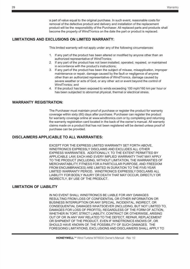
29 Warrantry
HONEYWELL™ Wind Turbine WT6500 Owner’s Manual - Rev 10
a part of value equal to the original purchase. In such event, reasonable costs for
removal of the defective product and delivery and installation of the replacement
product will be the responsibility of the Purchaser. All replaced parts and products shall
become the property of WindTronics on the date the part or product is replaced.
LIMITATIONS AND EXCLUSIONS ON LIMITED WARRANTY:
This limited warranty will not apply under any of the following circumstances:
1. If any part of the product has been altered or modied by anyone other than an
authorized representative of WindTronics;
2. If any part of the product has not been installed, operated, repaired, or maintained
in accordance with the product’s instructions;
3. If any part of the product has been the subject of misuse, misapplication, improper
maintenance or repair, damage caused by the fault or negligence of anyone
other than an authorized representative of WindTronics, damage caused by
severe weather or acts of God, or any other act or event beyond the control of
WindTronics; and
4. If the product has been exposed to winds exceeding 100 mph/160 km per hour or
has been subjected to abnormal physical, thermal or electrical stress.
WARRANTY REGISTRATION:
The Purchaser must maintain proof of purchase or register the product for warranty
coverage within sixty (60) days after purchase. Purchaser can register the product
for warranty coverage online at www.windtronics.com or by completing and returning
the warranty registration card located in the back of the owner’s manual. All warranty
claims made on a product that has not been registered will be denied unless proof of
purchase can be provided.
DISCLAIMERS APPLICABLE TO ALL WARRANTIES:
EXCEPT FOR THE EXPRESS LIMITED WARRANTY SET FORTH ABOVE,
WINDTRONICS EXPRESSLY DISCLAIMS AND EXCLUDES ALL OTHER
EXPRESS WARRANTIES. ADDITIONALLY, TO THE EXTENT PERMITTED BY
APPLICABLE LAW, EACH AND EVERY IMPLIED WARRANTY THAT MAY APPLY
TO THE PRODUCT (INCLUDING, WITHOUT LIMITATION, THE WARRANTIES OF
MERCHANTABILITY, FITNESS FOR A PARTICULAR PURPOSE, AND FREEDOM
FROM ENCUMBRANCES) ARE LIMITED IN DURATION TO THE FIVE-YEAR
LIMITED WARRANTY PERIOD. WINDTRONICS EXPRESSLY DISCLAIMS ALL
LIABILITY FOR BODILY INJURY OR DEATH THAT MAY OCCUR, DIRECTLY OR
INDIRECTLY, BY USE OF THE PRODUCT.
LIMITATION OF LIABILITY
IN NO EVENT SHALL WINDTRONICS BE LIABLE FOR ANY DAMAGES
RESULTING FROM LOSS OF CONFIDENTIAL OR OTHER INFORMATION OR
BUSINESS INTERRUPTION OR ANY SPECIAL, INCIDENTAL, INDIRECT, OR
CONSEQUENTIAL DAMAGES WHATSOEVER (INCLUDING, BUT NOT LIMITED TO,
DAMAGES FOR LOSS OF PROFITS), REGARDLESS OF THE FORM OF ACTION,
WHETHER IN TORT, STRICT LIABILITY, CONTRACT OR OTHERWISE, ARISING
OUT OF OR IN ANY WAY RELATED TO THE DEFECT, REPAIR, REPLACEMENT
OR SHIPMENT OF THE PRODUCT, EVEN IF WINDTRONICS KNOWS OF, OR
SHOULD HAVE KNOWN OF, THE POSSIBILITY OF SUCH DAMAGES. THE
FOREGOING LIMITATIONS, EXCLUSIONS AND DISCLAIMERS SHALL APPLY TO

8/3/2019 Gearless Wind Generator Owner's Manual
http://slidepdf.com/reader/full/gearless-wind-generator-owners-manual 37/46
30
HONEYWELL™ Wind Turbine WT6500 Owner’s Manual - Rev 10
Warrantry
THE MAXIMUM EXTENT PERMITTED BY APPLICABLE LAW. IN NO EVENT SHALL
WINDTRONICS’ AGGREGATE LIABILITY EXCEED THE AMOUNT ACTUALLY
RECEIVED BY WINDTRONICS FROM THE PURCHASER FOR THE PURCHASE OF
THE PRODUCT.
Some states and provinces do not allow the exclusion or limitation of incidental or
consequential damages, so the above limitations may not apply to you. No agent,
dealer, Service Company, or other party is authorized to change, modify, or extend theterms of this warranty in any manner whatsoever.
LEGAL REMEDIES:
This warranty gives you specic legal rights, and you may have other rights which vary
from state to state or province to province.
CHANGES TO THIS LIMITED WARRANTY:
WindTronics may change this warranty from time to time. When WindTronics makes
changes to the warranty, it will post them at www.windtronics.com. The warranty that
shall apply to a product shall be the warranty posted at the Website at the time theproduct is purchased. It is the Purchaser’s responsibility to check the Website to see if
the warranty posted there is different than the warranty stated herein.
GOVERNING LAW:
If the Purchaser purchases the product in the United States of America, this warranty
is governed by the laws of the State of Michigan and the applicable federal laws of
the United States. If the Purchaser purchases the product in Canada, this warranty
is governed by the laws of the Province of Ontario and the federal laws of Canada
applicable therein. In either case, the application of the United Nations Convention on
Contracts for the International Sale of Goods is expressly excluded.
8/3/2019 Gearless Wind Generator Owner's Manual
http://slidepdf.com/reader/full/gearless-wind-generator-owners-manual 38/46
31 Appendix
HONEYWELL™ Wind Turbine WT6500 Owner’s Manual - Rev 10
Appendix
Turbine Installation Drawings
For Information on: See:
Pole Mount 32
ROOFBOX ™ Mount 33
ROOFBOX ™ with QUADPOD™
Mounting
34
Ballast Mount 35
One Line Drawing 36-37
5
8/3/2019 Gearless Wind Generator Owner's Manual
http://slidepdf.com/reader/full/gearless-wind-generator-owners-manual 39/46
32
HONEYWELL™ Wind Turbine WT6500 Owner’s Manual - Rev 10
Appendix
Pole Mount
8/3/2019 Gearless Wind Generator Owner's Manual
http://slidepdf.com/reader/full/gearless-wind-generator-owners-manual 40/46
33 Appendix
HONEYWELL™ Wind Turbine WT6500 Owner’s Manual - Rev 10
ROOFBOX™ Mounting
8/3/2019 Gearless Wind Generator Owner's Manual
http://slidepdf.com/reader/full/gearless-wind-generator-owners-manual 41/46
34
HONEYWELL™ Wind Turbine WT6500 Owner’s Manual - Rev 10
Appendix
ROOFBOX™ with QUADPOD™ Mounting
8/3/2019 Gearless Wind Generator Owner's Manual
http://slidepdf.com/reader/full/gearless-wind-generator-owners-manual 42/46
35 Appendix
HONEYWELL™ Wind Turbine WT6500 Owner’s Manual - Rev 10
Ballast Mounting
8/3/2019 Gearless Wind Generator Owner's Manual
http://slidepdf.com/reader/full/gearless-wind-generator-owners-manual 43/46
36
HONEYWELL™ Wind Turbine WT6500 Owner’s Manual - Rev 10
Appendix
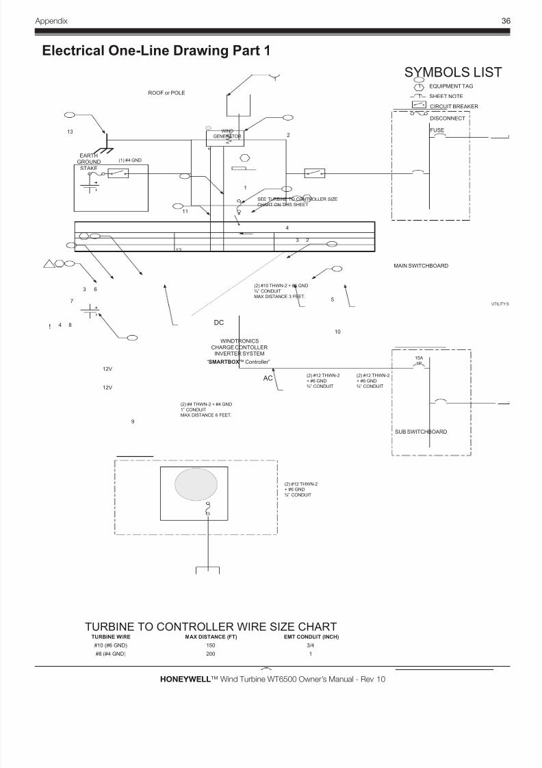
WINDTRONICS
CHARGE CONTOLLERINVERTER SYSTEM
“SMARTBOX™ Controller”
WIND
GENERATOR
ROOF or POLE
12V
15A
1P
MAIN SWITCHBOARD
UTILITY
DC
AC
15A
1P
SUB SWITCHBOARD
LOAD
12V
M
SEE TURBINE TO CONTROLLER SIZE
CHART ON THIS SHEET
3 2
1
1
57
3
10
8
9
6
12
11
SYMBOLS LIST1
1 SHEET NOTE
EQUIPMENT TAG
CIRCUIT BREAKER
DISCONNECT
FUSE
(2) #10 THWN-2 + #6 GND
¾” CONDUIT
MAX DISTANCE 3 FEET.
(2) #4 THWN-2 + #4 GND1” CONDUIT
MAX DISTANCE 6 FEET.
(2) #12 THWN-2
+ #6 GND
¾” CONDUIT
TURBINE TO CONTROLLER WIRE SIZE CHARTTURBINE WIRE MAX DISTANCE (FT) EMT CONDUIT (INCH)
#10 (#6 GND) 3/4
4
(2) #12 THWN-2
+ #6 GND
¾” CONDUIT
(2) #12 THWN-2
+ #6 GND
¾” CONDUIT
2
4
#8 (#4 GND) 1
!
150
200
EARTHGROUND
STAKE
(1) #4 GND
13
Electrical One-Line Drawing Part 1
8/3/2019 Gearless Wind Generator Owner's Manual
http://slidepdf.com/reader/full/gearless-wind-generator-owners-manual 44/46
37 Appendix
HONEYWELL™ Wind Turbine WT6500 Owner’s Manual - Rev 10
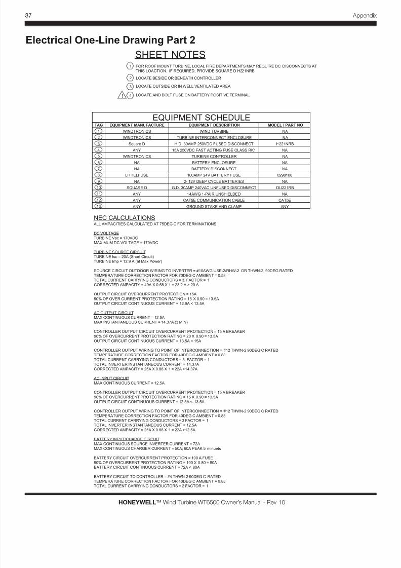
SHEET NOTES
EQUIPMENT SCHEDULETAG EQUIPMENT MANUFACTURE EQUIPMENT DESCRIPTION MODEL / PART NO
1 WINDTRONICS WIND TURBINE NA
2 WINDTRONICS TURBINE INTERCONNECT ENCLOSURE NA
1 FOR ROOF MOUNT TURBINE, LOCAL FIRE DEPARTMENTS MAY REQUIRE DC DISCONNECTS AT
THIS LOACTION. IF REQUIRED, PROVIDE SQUARE D H221NRB
2 LOCATE BESIDE OR BENEATH CONTROLLER
3 LOCATE OUTSIDE OR IN WELL VENTILATED AREA
3 Square D H.D. 30AMP 250VDC FUSED DISCONNECT H221NRB`
4 ANY 15A 250VDC FAST ACTING FUSE CLASS RK1 NA
5 WINDTRONICS TURBINE CONTROLLER NA
6 NA BATTERY ENCLOSURE NA
7 NA BATTERY DISCONNECT NA
8 LITTELFUSE 100AMP 24V BATTERY FUSE 0298100
9 NA 2- 12V DEEP CYCLE BATTERIES NA`
10 SQUARE D G.D. 30AMP 240VAC UNFUSED DISCONNECT DU221RB`
11 ANY 14AWG 1-PAIR UNSHIELDED NA`
12 ANY CAT5E COMMUNICATION CABLE CAT5E`
4 LOCATE AND BOLT FUSE ON BATTERY POSITIVE TERMINAL
NEC CALCULATIONSALL AMPACITIES CALCULATED AT 75DEG C FOR TERMINATIONS
DC VOLTAGE
TURBINE Voc = 170VDC
MAXIMUM DC VOLTAGE = 170VDC
TURBINE SOURCE CIRCUITTURBINE Isc = 20A (Short Circuit)
TURBINE Imp = 12.9 A (at Max Power)
SOURCE CIRCUIT OUTDOOR WIRING TO INVERTER = #10AWG USE-2/RHW-2 OR THWN-2, 90DEG RATED
TEMPERATURE CORRECTION FACTOR FOR 70DEG C AMBIENT = 0.58
TOTAL CURRENT CARRYING CONDUCTORS = 3, FACTOR = 1
CORRECTED AMPACITY = 40A X 0.58 X 1 = 23.2 A > 20 A
OUTPUT CIRCUIT OVERCURRENT PROTECTION = 15A
90% OF OVER CURRENT PROTECTION RATING = 15 X 0.90 = 13.5AOUTPUT CIRCUIT CONTINUOUS CURRENT = 12.9A < 13.5A
AC OUTPUT CIRCUIT
MAX CONTINUOUS CURRENT = 12.5A
MAX INSTANTANEOUS CURRENT = 14.37A (3 MIN)
CONTROLLER OUTPUT CIRCUIT OVERCURRENT PROTECTION = 15 A BREAKER
90% OF OVERCURRENT PROTECTION RATING = 20 X 0.90 = 13.5A
OUTPUT CIRCUIT CONTINUOUS CURRENT = 13.5A < 15A
CONTROLLER OUTPUT WIRING TO POINT OF INTERCONNECTION = #12 THWN-2 90DEG C RATED
TEMPERATURE CORRECTION FACTOR FOR 40DEG C AMBIENT = 0.88
TOTAL CURRENT CARRYING CONDUCTORS = 3, FACTOR = 1
TOTAL INVERTER INSTANTANEOUS CURRENT = 14.37A
CORRECTED AMPACITY = 25A X 0.88 X 1 = 22A >14.37A
AC INPUT CIRCUIT
MAX CONTINUOUS CURRENT = 12.5A
CONTROLLER OUTPUT CIRCUIT OVERCURRENT PROTECTION = 15 A BREAKER
90% OF OVERCURRENT PROTECTION RATING = 15 X 0.90 = 13.5AOUTPUT CIRCUIT CONTINUOUS CURRENT = 12.5A < 13.5A
CONTROLLER OUTPUT WIRING TO POINT OF INTERCONNECTION = #12 THWN-2 90DEG C RATED
TEMPERATURE CORRECTION FACTOR FOR 40DEG C AMBIENT = 0.88
TOTAL CURRENT CARRYING CONDUCTORS = 3 FACTOR = 1TOTAL INVERTER INSTANTANEOUS CURRENT = 12.5A
CORRECTED AMPACITY = 25A X 0.88 X 1 = 22A >12.5A
BATTERY INPUT\CHARGE CIRCUIT
MAX CONTINUOUS SOURCE INVERTER CURRENT = 72A
MAX CONTINUOUS CHARGER CURRENT = 50A; 60A PEAK 5 minuets
BATTERY CIRCUIT OVERCURRENT PROTECTION = 100 A FUSE
80% OF OVERCURRENT PROTECTION RATING = 100 X 0.80 = 80A
BATTERY CIRCUIT CONTINUOUS CURRENT = 72A < 80A
BATTERY CIRCUIT TO CONTROLLER = #4 THWN-2 90DEG C RATED
TEMPERATURE CORRECTION FACTOR FOR 40DEG C AMBIENT = 0.88TOTAL CURRENT CARRYING CONDUCTORS = 2 FACTOR = 1
!
13 ANY GROUND STAKE AND CLAMP ANY`
Electrical One-Line Drawing Part 2

8/3/2019 Gearless Wind Generator Owner's Manual
http://slidepdf.com/reader/full/gearless-wind-generator-owners-manual 45/46
38
HONEYWELL™ Wind Turbine WT6500 Owner’s Manual - Rev 10
Appendix

8/3/2019 Gearless Wind Generator Owner's Manual
http://slidepdf.com/reader/full/gearless-wind-generator-owners-manual 46/46
WindTronics
The Honeywell Trademark is used under license
from Honeywell International Inc.and makes no
representations or warranties with respect to this product.