Embed Size (px)
Citation preview
BEFORE THE PUBLIC UTILITIES COMMISSION OF THE STATE OF SOUTH DAKOTA
In the Matter of the Transmission Permit for the Big Stone South to Ellendale Project
EL13-028
DIRECT TESTIMONY OF JON LEMAN
EXHIBIT Page 1of11
1 ao
1 BACKGROUND OF WITNESS
2 Q. Please state your name, employer, and business address.
3 A. My name is Jon Leman. I work for POWER Engineers, Inc. ("POWER"). My
4 business address is 1300 16111 Ave, Suite 200, Clarkston, WA 99403.
s Q. What is your current position with POWER?
6 A. Senior Project Engineer and Area Lead - electrical system studies.
7 Q. What are your duties and responsibilities in that position?
8 A. Electrical design and analysis of AC and DC power delivery systems, including
9 transmission lines. As part of that work, I coordinate and prepare engineering studies regarding
10 conductor (line) insulation, corona effects, electrical and magnetic field, effects, conductor and
11 shield wire selection, transient studies, power system planning, protective relaying, and arc flash.
12 I also supervise other electrical engineers in POWER's Clarkston, WA office.
13 Q. How long have you worked for POWER?·
14 A. Since June of2005.
15 Q. How long in your current position?
16 A. Approximately two and one-half years.
17 Q. Can you describe your work experience before your cmrrent position.
18 A. Prior to my current position I worked as a junior engineer, mid level engineer, and
19 project engineer in POWER's SCADA and Analytical Services (electrical studies) business unit.
20 Prior to POWER I worked for the United States Navy as an electrical engineering instructor.
21 Q. What is your education?
Page 2of11
1 A. I received a Bachelor of Science in electrical engineering from the University of
2 Idaho in 2001. In 2010, I received a Master of Science degree in electrical engineering from the
3 University ofldaho.
4 Q. Are you a licensed engineer?
5 A. Yes, I am a licensed electrical engineer in the State of Idaho.
6 Q. Do you have any prior experience working on electrical transmission lines?
7 A. Yes, most of my career at POWER has involved electrical analysis of transmission
8 lines and I have been involved in many projects prior to this one. Much of my experience is with
9 345 kV transmission lines though I have also worked with many other projects ranging from 35
10 kV sub-transmission through 500 kV transmission projects.
11 Q. What is exhibit 15?
12 A. This is my a copy of my curriculum vitae.
13 Q. Is it true and accurate?
14 A. Yes.
15 Q. What is the purpose of your testimony?
16 A. I am going to testify about the electrical engineering issues arising out of the
17 construction and operation of the transmission line.
18 ROLE IN THE PROJECT
19 Q. What is your role in the Big Stone South to Ellendale Project ("Project")?
20 A. I have performed electrical design activities and have assisted in addressing some of
21 the purported electrical engineering concerns arising out of the construction of the Project,
22 including concerns about electrical fields, magnetic fields, and stray voltage associated with the
23 project.
Page 3of11
1
2
3
4
5
6
7
8
9
10
11
12
13
14
15
16
17
18
19
Q. Have you reviewed any studies or research as part of your work on the Project'!
A. Yes. In performing my work, I reviewed the following:
1. National Electrical Safety Code (NESC), Institute of Electrical and Electronics
Engineers (IEEE), 2012
2. IEEE Std. C95. 6, Standard/or Safety Levels with Respect to Human Exposure to Electromagnetic Fields, 0-JkHz, Institute of Electrical and Electronics Engineers (IEEE),
2002
3. JCNJRP Guidelines/or Limiting Exposure to Time-Varying Electric, Magnetic and
Electromagnetic Fields (up to 300 GHz), International Commission on Non-Ionizing
Radiation Protection, 1998
4. Field and Wave Electromagnetics, 2"d ed., D. K. Cheng, 1992
5. EPRI Transmission Line Reference Book, 200 kV and Above 3•·d ed., 2005
6. Corona Performance of High Voltage Transmission Lines, P. S. Maruvada, 2000
20 7. Electric and Magnetic Fields Associated with the Use of Electric Power --
21 Questions and Answers, National Institute of Environmental Health Services (NIEi-IS),
22 2002
23 Q. Are these studies or research the type of information an electrical engineer
24 would commonly rely on in performing electrical engineering services?
25 A. Yes, they are.
26 Q. Has POWER performed any engineering studies relating to your work on the
27 Project?
28 A. Yes, POWER performed a conductor optimization study. In the conductor
29 optimization study, POWER analyzed the options for selecting conductors (lines) for the Project.
30 In analyzing the conductor options, POWER modeled the electric and magnetic fields (EMF) and
31 corona effects associated with the Project. POWER also performed studies to confirm whether
Page 4of11
1 the Project's design will comply with National Electric Safety Code (NESC), which requires that
2 any induced currents due to electric fields do not exceed a specified level.
3 Q. What was your role regarding these two studies?
4 A I supervised the creation of the two studies by POWER. I have reviewed both
5 studies.
6 Q. Are these studies the type of information an electrical engineer would commonly
7 rely on in performing electrical engineering services?
8 A. Yes, they are.
9 ISSUES WITH ELECTRICAL AND MAGNENTIC FIELDS (EMF)
10 Q. Do high voltage transmission lines like the 345kV transmission line as part of the
11 Project create an electrical field?
12 A. Yes, high voltage transmission lines, like power Jines of all voltages, create both
13 electric fields and magnetic fields, which are collectively referred to as EMF.
14 Q. What did the conductor optimization study indicate regarding the effects of the
15 EMF?
16 A. The design of the Project results in EMF levels that are lower than the levels
17 recommended by the Institute of Electrical and Electronic Engineers (IEEE), who issue standards
18 and guidelines for the industry. The EMF levels are also below the recommendation of
19 International Commission on Non-Ionizing Radiation Protection (ICNIRP), who have done
20 studies on the effects of EMF and published guidelines for exposure limits. Also. the Project's
21 design meets the safety requirements imposed by the NESC.
22 Q. Are there any potential issues arising from the electrical fields created by the
23 transmission line for the project?
Page 5of11
1 A. Yes, like all high voltage transmission lines, there are some potential effects due to
2 the electric field interactions between the high voltage transmission line of the Project and
3 metallic objects near the transmission line. Depending on the design of the transmission line, the
4 electrical field can cause stray voltage in metallic objects. Also, electric fields from high voltage
5 transmission lines ionize the air around the conductor resulting in corona. Corona can cause
6 audible noise (AN), radio interference (RI), and television interference (TV!). The conversion of
7 television transmission to digital eliminated most problems with TVI.
s Q. What has POWER done to address those issues?
9 A. POWER has designed the line to meet National Electrical Safety Code (NESC)
10 clearance requirements. These clearance requirements prevent electric fields from being strong
11 enough at ground level to cause a harmful shock if a person touches a large metallic object. An
12 example of such an object would be the chassis of a semi tractor-trailer or farm equipment
13 parked within the influence of the transmission line electric field. The larger the metal surface
14 area of the object and the closer to the transmission line, the greater the risk of the electrical field
15 creating a shock. By designing to NESC requirements, the risk associated with electric fields is
16 mitigated. Additionally, the conductor size, conductor bundles, phase spacing, and other line
17 geometry are designed to minimize corona audible noise and radio interference effects.
18 Ultimately, the conductor optimization study indicates that the EMF and corona effects of the
19 transmission line meet NESC requirements, industry guidelines, and design specifications.
20 Q. Are there any safety issues to people from the electrical field created by the
21 Project?
22 A. No, both the conductor optimization study and the NESC clearance study establish
23 that the electric field created by the transmission line does not pose a safety hazard.
Page 6of11
1 Q. Are there any safety concerns for livestock or wildlife?
2 A. No. Livestock and terrestrial wildlife will not experience electrical fields any higher
3 than humans, and the compliance of the transmission line with the NESC design clearances
4 means no electric field safety hazard to animals on the ground.
s Q. When constructed and energized, will the transmission line create a magnetic
6 field?
7 A. Yes, it will create a magnetic field when current flows in the conductors.
8 Q. Do these magnetic fields create any issues?
9 A. Yes, magnetic fields from current on high voltage transmission lines can induce
10 voltages in parallel facilities (e.g., fences, railroads, pipelines). In poorly designed systems, this
11 can lead to corrosion, shock, or service interruption on the parallel facility. The Project's design
12 and routing avoid these problems.
13 Q. What has POWER done to address those issues?
14 A. POWER designed the line according to NESC clearances which help reduce the
15 effect of induced voltages due to magnetic fields. Also, the transmission line does not parallel
16 any railroads or pipeline facilities. For locations with equipment such as fencing, mitigation
17 options are well known in industry and will be dealt with on a case by case basis via grounding,
18 filters, etc.
19 Q. Does the Project pose any safety issues to people based as a result of the
20 magnetic fields?
21 A. No, because there are no parallel railroad and pipeline facilities, and because the
22 Project will employ industry standard mitigation methods for fencing and other equipment.
Page 7of11
1 Q. Ilio magnetic fields cireated by the Pwoject pose any safety risk for livestock or
2 wildlife?
3 A. No. The safety risk to livestock and terrestrial wildlife of a magnetic field is the same
4 as humans.
s STRAY VOLTAGE ISSUES
6 Q. What is stray voltage?
7 A. Stray voltage is an accidental difference in electrical potential between two objects
8 during normal operation of an energy delivery system. In other words, it is a situation in which
9 voltage (or electrical current) is present where not intended.
10 Q. Can transmission lines cause stray voltage?
11 A. As indicated in Section 23.4.4 of the Application, transmission lines alone typically
12 do not cause stray voltage. Instead, stray voltage typically comes from distribution lines rather
13 than transmission lines. Additionally, in some circumstances, the EMF from transmission lines
14 can induce stray voltage on large metallic objects very close to the line. Stray voltage due to
15 insulation deterioration is possible but less likely.
16 Q. What has POWER done to address stray voltage for the transmission line?
17 A The design clearance of the transmission line consistent with NESC guidelines
18 prevents the inducement of excessive voltages from EMF on large metal objects near the
19 transmission line. Regarding the insulators, the project will perform regular maintenance of the
20 transmission line as described in Section 22.4 of the Application.
21 Q. Have engineering studies been performed regarding the issue of stray voltage?
22 A. Yes, these are the same engineering studies that I testified about regarding electrical
23 fields.
Page 8of11
1 Q. What do those st1J1dies indicate?
2 A. They indicate that the transmission line's clearance design is sufficient to limit
3 induced currents caused by stray voltage to levels that comply with NESC requirements.
4 Q. What affect does stray voltage have in locating a transmission line in
5 comparison to a railroad track?
6 A. If a transmission line runs parallel to a railroad track, there is a risk of stray voltage.
7 As a result, if a project has the potential to be near a railroad track, studies are done to identify
8 stray voltage and electromagnetic issues. If issues are identified the line is either routed farther
9 from the track or mitigation is implemented to eliminate or reduce the effects. This is not an
10 issue with the Project, however, because no known railroads are near the preferred route for the
11 Project.
12 Q. Do you have an opinion regarding whether the construction or operation of the
13 transmission line will result in stray voltage that will affect farming operations,
14 vehicle usage, or location of metal buildings?
15 A. Yes, I have an opinion.
16 Q. What is your opinion?
17 A. The Project will not cause stray voltage that will affect farming operations, vehicle
18 usage, or location of metal buildings. Although large metallic objects (such as large vehicles or
19 metal buildings) can experience electrostatic induced voltages due to electric fields from power
20 lines, the clearance of the Project is designed to meet NESC requirements for large farm
21 combines and semi tractor-trailers. Vehicles up to these sizes should not have any issues with
22 stray voltage. Metallic buildings that are very close to the transmission line may require
23 grounding to eliminate electric field effects. There are no metallic buildings in the right-of-way.
Page 9of11
1 If there are any metallic buildings outside the right-of~way that are close enough and large
2 enough to create stray voltage issues, the Project will work with the landowner to address the
3 issue dming the construction process by using industry standard mitigation techniques.
4 GLOBAL Y POSITIONING SYSTEM COPS) ISSUES
5 Q. IJio you foresee any issues with the transmission line negatively affecting GPS for
6 farming?
7 A. As indicated in interrogatory answer no. 12 of Gerald Pesall's First Set of Discovery
8 Requests to Applicants, which is Exhibit 4 attached to Henry Ford's direct testimony, isolated
9 cases of interference are possible but unlikely. Electric field corona from high voltage power
10 lines can produce radio frequency emissions, but these radio frequency emissions are generally at
11 a lower frequency than the frequencies used for satellite OPS systems. Individual transmission
12 structures near OPS based farm equipment may block or reflect GPS signals like a building
13 would, but the presence of multiple OPS satellites usually prevents this from being a significant
14 lSSUe.
15 Q. What is the effect of transmission line on ground based GPS? ' f-
16 A. Isolated cases of corona based interference from transmission lines are possible, but
17 unlikely. Interference effects lend lo be very location specific and also depend on the location
18 and type of antennas, weather conditions, presence of other radio frequency noise sources, etc.
19 Ground based OPS can also be impacted by transmission structures, but the effects are similar to
20 trees, buildings or other obstructions that can block line-of-site communications between OPS
21 base stations and roving equipment. As with any other line-of-site obstruction this issue can be
22 overcome by relocating the base station or using repeater stations.
Page 10of11
1 Q. Based on your experience, education, training, research, and work on the
2 project, do you have an opinion regarding whether the construction, operating, or
3 maintaining of the South Dakota facility, from an electrical engineering perspective, will
4 cause any significant problems (i.e., electrical fields, magnetic fields, stray voltage) for
5 landowners, their families, and other inhalbitants where the line is anticipated to be
6 constructed?
7 A. Yes, I have an opinion.
8 Q. What is that opinion?
9 A. From an electrical engineering perspective, the construction and operation of the
10 transmission line will not create significant problems.
11 Q. Does this complete your direct testimony?
12 A. Yes.
13
Page 11of11
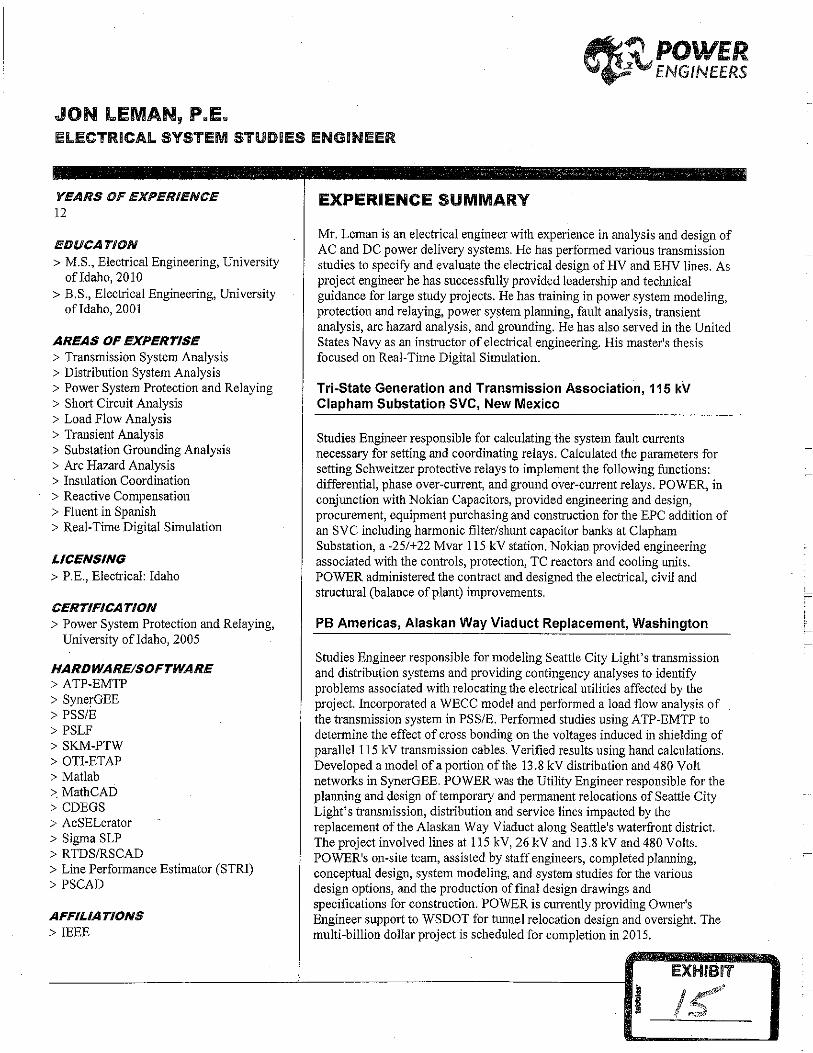
JON LEMAN, P.E.
~~POWER \,l~'\.rl ENGINEERS
IEl.ECTRICAl SYSTEM STUDIES ENGINEER
YEARS OF EXPERIENCE 12
EDUCATION > M.S., Electrical Engineering, University
ofldaho,2010 > B.S., Electrical Engineering, University
ofldaho,2001
AREAS OF EXPERTISE > Transmission System Analysis > Distribution System Analysis > Power System Protection and Relaying > Short Circuit Analysis > Load Flow Analysis > Transient Analysis > Substation Grounding Analysis > Arc Hazard Analysis > Insulation Coordination > Reactive Compensation > Fluent in Spanish > Real-Time Digital Simulation
LICENSING > P.E., Electrical: Idaho
CERTIFICATION > Power System Protection and Relaying,
University ofldaho, 2005
HARDWARE/SOFTWARE > ATP-EMTP > SynerGEE > PSS/E > PSLF > SKM-PTW > OTI-ETAP >Matlab > MathCAD > CDEGS > AcSELerator >Sigma SLP > RTDS/RSCAD > Line Performance Estimator (STRI) > PSCAD
AFFILIATIONS >IEEE
EXPERIENCE SUMMARY
Mr. Leman is an electrical engineer with experience in analysis and design of AC and DC power delivery systems. He has performed various transmission studies to specify and evaluate the electrical design of HV and EHV lines. As project engineer he has successfully provided leadership and technical guidance for large study projects. He has training in power system modeling, protection and relaying, power system plarming, fault analysis, transient analysis, arc hazard analysis, and grounding. He has also served in the United States Navy as an instructor of electrical engineering. His master's thesis focused on Real-Time Digital Simulation.
Tri-State Generation and Transmission Association, 115 kV Clapham Substation SVC, New Mexico
Studies Engineer responsible for calculating the system fault currents necessary for setting and coordinating relays. Calculated the parameters for setting Schweitzer protective relays to implement the following functions: differential, phase over-current, and ground over-current relays. POWER, in conjunction with Nokian Capacitors, provided engineering and design, procurement, equipment purchasing and construction for the EPC addition of an SVC including harmonic filter/shunt capacitor banks at Clapham Substation, a -25/+22 Mvar 115 kV station. Nokian provided engineering associated with the controls, protection, TC reactors and cooling units. POWER administered the contract and designed the electrical, civil and structural (balance of plant) improvements.
PB Americas, Alaskan Way Viaduct Replacement, Washington
Studies Engineer responsible for modeling Seattle City Light's transmission and distribution systems and providing contingency analyses to identify problems associated with relocating the electrical utilities affected by the project. Incorporated a WECC model and performed a load flow analysis of the transmission system in PSS/E. Performed studies using ATP-EMTP to determine the effect of cross bonding on the voltages induced in shielding of parallel 115 kV transmission cables. Verified results using hand calculations. Developed a model of a portion of the 13 .8 kV distribution and 480 Volt networks in SynerGEE. POWER was the Utility Engineer responsible for the planning and design of temporary and permanent relocations of Seattle City Light's transmission, distribution and service lines impacted by the replacement of the Alaskan Way Viaduct along Seattle's waterfront district. The project involved lines at 115 kV, 26 kV and 13.8 kV and 480 Volts. POWER's on-site team, assisted by staff engineers, completed planning, conceptual design, system modeling, and system studies for the various design options, and the production of final design drawings and specifications for construction. POWER is currently providing Owner's Engineer support to WSDOT for tunnel relocation design and oversight. The multi-billion dollar project is scheduled for completion in 2015.
EXHIB~T
1<·' f ,...~..,,.o/
JON LEMAN, P.E. I 2
> PES
POWER ENGINEERS, INC.
Southern California Edison, Substation Grounding Projects, California
Studies Engineer who conducted grounding studies at a number of SCE substations. Analyzed soil measurements to develop a model of substation soil conditions. Designed and modeled upgrades for the grounding systems of existing substations. During a two-year period, POWER assisted SCE in conducting grounding studies at 22 SCE substations that had undergone upgrades or additions. SCE provided soil resistivity measurements, fault current values, and substation drawings showing the existing stations and the planned improvements. POWER modeled the ground grid system and performed analyses using Safe Engineering Service's CDEGS software to verify that the grounding systems at these substations were within IEEE Standard 80-2000 guidelines for step and touch potentials. POWER designed grounding system upgrades for substations that did not meet the IEEE 80 requirements.
Babcock & Brown, Sweetwater IV Wind Farm, Texas
Studies Engineer responsible for analyzing wind farm electrical performance. Performed comparative analysis of 138 kV vs. 345 kV transmission voltages, sizing of shunt reactive compensation, and transmission loss analysis based on an annual wind generation profile. Babcock and Brown initiated the expansion of the existing Sweetwater Wind development an additional 135 MW of wind generation. Babcock and Brown initiated the expansion of the existing Sweetwater Wind development to accommodate an additional 135 MW of wind generation. POWER was responsible for complete electrical design of the 135 x I MW Mitsubishi turbine farm. POWER was responsible for the complete 34.5 kV underground and overhead collection system, 34.5/345 kV substation, SCADA and protective relaying and the 345 kV transmission line connecting expansion to the existing switchyard infrastructure.
U.S. Trade and Development Agency, Electricite d'Haiti Technical Assistance Project, Haiti
Studies Engineer responsible for perfo1ming load flow and short circuit analyses for Haiti's Port-au-Prince transmission system. Developed a computer model of the system in ETAP. Created 10-year load projections and incorporated transmission system upgrades in the ETAP model to accommodate the expected growth. POWER conducted a series of electrical studies to assess the current state of the island nation's electric generation and delivery system and identify priority reconstruction projects. The project provided recommendations to improve the generation, transmission and distribution system to meet world accepted reliability and safety standards.
Princeton University, Elm/Charlton Relay Settings, New Jersey
Studies Engineer responsible for developing protective relay settings. Calculated fault currents and relay settings for differential, phase overcurrent and ground overcurrent functions for system protection. Princeton needed engineering support to develop protective relay settings and coordination analysis for several protective relays at the Elm Drive and Charlton Street Substations. POWER standardized settings files for SEL-551
JON LEMAN, P.E. I 3 POWER ENGINEERS, INC.
relays to provide consistency in the relaying approach for the feeders. Implemented arc flash instantaneous overcurrent elements to reduce incident energy levels providing additional safety for workers while exposed during maintenance activities.
Mitsubishi Electric Power Products, Rector Substation SVC, California
Studies Engineer for the installation of a static var compensator (SVC) at Southern California Edison's Rector Substation. Responsible for calculating the short circuit bus forces for a horizontal, six-conductor 9.5 kV bus arrangement. Created a model of the system in ATP-EMTP and performed transient analysis to determine the asymmetrical fault currents for threephase bus faults. Performed a series of transient simulations with varying fault inception angles in order to identify the worst possible bus forces necessary for use in structural specification. POWER was a subcontractor to Mitsubishi Electric Power Products, the EPC contractor. The new system provides -120 to +200 Mvar continuous compensation. POWER's scope included complete physical arrangement, busing, foundation, structures, static protection, lighting, grounding, protection and control, wiring, control shelter, station service, relay settings, testing and commissioning, and fiber optic communications with SCE.
Enbridge Energy, 2006 Arc Flash Study, Wisconsin
Project Engineer responsible for coordinating arc flash studies of 16 pumping stations. Assisted the Project Manager in writing the scope of work, budget and schedule. Trained and supervised four studies engineers involved in performing the arc flash analysis. Provided technical review of the arc flash study results. POWER performed arc flash studies at 16 pipeline pumping stations to minimize fault clearing times and reduce arc flash hazards to employees. POWER also performed software model verification of electrical systems, conducted three phase balanced fault studies and verified relay coordination for transformer and motor protection. POWER proposed recommendations for relay settings and equipment changes to lower incident energies to be within IEEE recommended safety levels.
Brazos Electric Cooperative, Hugo to Valley South 345 kV Project, Texas
Studies Engineer responsible for load flow studies of70 miles of345 kV transmission line planned to carry up to 1000 MW of power into Texas. Studies were performed using an ERCOT database in PSS/E in order to size reactors for limiting open end voltage rises on the line. The engineering studies concentrated on the capability ofa 345 kV double circuit transmission line and the HVDC tie to transfer bi-directional flows varying from 400 MW to 1200 MW. Equipment design requirements were established to control the system voltage and reactive power flows. POWER also evaluated asynchronous tie technologies to include HVDC thyristor controls (classic), HVDC voltage source converters (VSC), and variable frequency transformers (VFT) to determine the best technology based on life cycle costs of the project. Teshmont Consultants were subcontracted to assist in preparation of an EPC specification for the HVDC tie. The project was cancelled prior to the start of the contracts for the HVDC equipment or line right-of-way procurement.
JON LEMAN, P.E. / 4 POWER ENGINEERS, INC.
Tesoro, Golden Eagle 230/15 kV Switching Station, California
Studies Engineer responsible for developing a software model of the new Golden Eagle.refinery substations using ETAP and performing load flow and short circuit analysis. Performed a coordination study and prepared protective relay settings and criteria for a 230 kV breaker failure scheme, transformer and bus differential protection, and phase and ground overcurrent protection. Developed custom logic for an auto transfer scheme used to more quickly recover substation loads in the event of the loss of one source to the 2.4 kV substation bus. Prepared mirrored bit communication settings. Protective devices included Schweitzer 351A, 387-6, 587Z, 551, 351-6, 31 IL, and 2100 relays. Voltages included 230 kV, 12.47 kV, and 2.4 kV.
Central Maine Power Company, Heywood 115 kV Switchyard and Transmission Interconnection, Maine
Studies Engineer responsible for developing protective relays settings for station bus differential relays, breaker failure relays, and pilot protection relays for the Heywood-Winslow transmission line. The work was part of POWER's design and commissioning of the new Heywood Road switchyard and transmission interconnection. POWER performed the transmission line work to interconnect two existing 115 kV lines to the new station, and modified a third 115 kV line and two 34.5 kV circuits in the area. POWER provided complete substation engineering including construction drawings, complete protection and control design, specifications, contractor bid documents, construction monitoring, commissioning and relay settings.
Enbridge Energy, 2007 Arc Flash Study, Wisconsin
Project Engineer responsible for developing a project work plan, coordinating field engineers and supervising studies engineers involved in the arc flash analysis. Also responsible for ensuring thorough technical reviews of the work are completed for each station. Served as client point of contact for technical issues. Provided arc flash and software training to project team. Enbridge contracted POWER to perform arc flash studies at 52 crude oil pumping stations in 10 states to minimize fault clearing times and reduce the risk of arc flash hazards to employees. POWER also recommended system changes and provided options for implementation. POWER developed a strategy for performing data acquisition, site visits, arc flash and coordination studies. The arc flash studies and coordination analysis of several stations were performed using SKM PTW and IEEE 1584-2002 guidelines.
Mirant, Arc Flash Hazard Analysis, Multiple Locations
Project Engineer responsible for communicating with the client and tracking the schedule and budget. Also coordinated technical work through team leads and served as arc flash technical reference. POWER provided arc flash, coordination and device evaluation analysis for ten of Mirant's major ( 400 to 2,300 MW) generating facilities. Tasks included on-site data acquisition and development of plant electrical models in SKM PTW. Short circuit analysis was performed to evaluate protective device ratings. Arc flash analysis was performed to identify incident energies and personal protective equipment (PPE) levels for working near energized equipment. Changes to protective
JON LEMAN, P.E. I 5 POWER ENGINEERS, INC.
device equipment and settings were recommended.
Kenny Construction Company, 500 kV Trans Allegheny Interstate Line, Multiple States
Studies Engineer responsible for performing electrical studies to support design of 500 kV and 138 kV transmission lines, including double circuit lines. Performed analysis to develop a short circuit thermal rating for optical ground wire specifications. Provided an economic comparison of the costs of segmenting optical ground wire versus losses for a non segmented configuration. Calculated the voltages induced on shield wire segments due to electromagnetic coupling with phase conductors. Performed a ground clearance study by calculating the transmission line electric field profile and determining the NESC short circuit currents of vehicles in or near the right of way. POWER also provided corona analysis for television and radio interference, AC interlerence studies, communications interference, and lightning analysis. POWER was the design and permitting contractor for a 160-mile line that spans Allegheny Energy's service territory from SW Pennsylvania through West Virginia to northern Virginia. POWER provided environmental resource studies and jurisdictional permitting and licensing services, and detailed transmission line engineering and design, including material specification and establishing new line and structure design criteria.
First Wind, Milford Wind Corridor Project, Utah
Lead Studies Engineer responsible for transmission line electrical analysis and design support; optical ground wire sizing studies; protective relay settings development; and capacitor bank control development. Transmission design studies include line constants, load flow, short circuit, transient switching, and shield wire sizing. Performed analysis to determine transmission line constants and calculated line losses as a function of wind farm generation. Determined switched shunt compensation necessary to meet interconnection VAR exchange limits. Protective relaying includes communication aided distance relays, transformer and bus differential protection, feeder overcurrent protection, and custom logic for capacitor bank switching. The project is a 200 MW wind farm in southwestern Utah. POWER provided engineering support for permitting; extensive electrical studies to determine integration requirements and equipment specifications; and design of a 90-mile 345 kV transmission line and 345-34.5 kV collector substation. POWER managed materials acquisition of major equipment; provided construction inspection and observation; and performed acceptance testing services for the collector substation.
NorthWestern Energy, Mountain States Transmission lntertie Electrical Studies, Multiple States
Studies Engineer responsible for performing conductor optimization, reactor sizing, and series capacitor sizing studies for the Mountain States Intertie. Used ATP-EMTP to develop line constants models and to verify steady state open-end voltage rise. Performed a transient switching study to calculate critical flashover rates for specifying insulator strings and to identify locations for installation of surge arresters. Implemented the line models in a WECC database and performed load flow analysis using PSS/E. POWER performed extensive electrical system studies for development of a proposed 430-mile, 500 kV transmission line from southwest Montana to south central
JON LEMAN, P.E. I 6 POWER ENGINEERS, INC.
Idaho.
TransWest Express, ±600 kV HVDC Transmission Line, Wyoming, Colorado, Utah, Nevada
Studies Engineer responsible for the HVDC insulator specification and electrical studies for a new HVDC transmission line to deliver power to load centers in the southwestern U.S. Studies include HVDC ground electrode placement and design and geological analysis, PSCAD simulation of switching transients and operating points, calculation of estimated corona losses, audible noise and radio interference for HVDC line at different altitudes and weather conditions. Worked with vendors to obtain the latest information about ceramic, glass, and polymer insulaiors. POWER is performing Owner's Engineer services for the project, including preliminary engineering to support project development and engineering support to the routing, siting and environmental permitting. The project is 725 miles of ±600 kV HVDC transmission line capable of transmitting 3,000 MW of wind generation from south central Wyoming to south of Las Vegas.
South Texas Electric Cooperative, Bakersfield to Big Hill CREZ 345 kV Transmission Line, Texas
Lead Studies Engineer responsible for coordinating electrical studies to support transmission line design. Tasks included insulation coordination (lighting, voltage transients, and NESC clearances), electrical enviromnental studies (EMF, radio/TV interference, audible noise, and corona), and NESC 5 mA calculations. Worked with project engineering and project manager to incorporate electrical considerations into the line design. POWER is providing engineering services for the design and construction of the 111 mile Bakersfield to Big Hill 345 kV CREZ transmission line. POWER's responsibilities include project management; pre-design studies including structure studies, line estimates and route selection support; survey and geotechnical coordination; line design; material procurement; construction support; and construction management including material control and construction inspection.
Clean Line Energy Partners, Plains & Eastern HVDC Line, Multiple Locations
Studies Engineer responsible for coordinating and checking insulation coordination studies. Performed contamination analysis, lightning studies, transient overvoltage and NESC clearances. The project is an 800-mile, 600 kV HVDC transmission line from the Oklahoma panhandle to Memphis, Tennessee. POWER developed conceptual design information including preliminary design criteria, conductor and OPGW selection, proposed and alternative structures, structure foundations, and structure spotting/line design. POWER also performed preliminary studies for insulation and electrical clearances, economic conductor selection, and EMF/EM! performance.
Confidential European Client, Wind Park Grid Code Compliance, Romania
Project Engineer responsible for technical direction for grid code compliance analyses at 41 wind parks in Europe. POWER verified the wind parks'
JON LEMAN, P.E. I 7 POWER ENGINEERS, INC.
performance characteristics complied with the requirements of the national and local grids and recommended design or equipment modifications when a park's performance was incompatible. The work involved data acquisition, data review, compliance gap analysis, high-level recommendations to bring the projects into compliance, and a report of the findings and recommendations. The projects were in Romania, Kazakhstan, Russia, Czech Republic, Bulgaria, Ukraine, and Serbia.
Sun Power Corporation, 25 MW McHenry Solar Farm, California
Project Engineer responsible for electrical design studies including load flow and short circuit, harmonic susceptibility analysis, grounding performance, arc flash, and protective relaying. The project is a 25 MW AC Solar Farm that will export power directly to the utility grid at 34.5 kV for Modesto Irrigation District. The solar panels will be installed on a steel single-axis horizontal tracker. As Owner's Engineer, POWER provided all drawings to construct the site and furnished the design for the two-breaker collection substation and for the utility three-breaker ring bus. POWER also worked with the utility on the interconnect, protection and SCADA system designs.
Otter Tail Power Company, Montana Dakota Utilities, Big Stone South to Ellendale 345 kV Transmission Line, Multiple States
Studies Engineer responsible for . This multi-value, jointly-owned, 165-mile 345 kV transmission line project is integral to the MISO transmission network to improve reliability, increase system capacity, and support public policy. POWER is providing overall project coordination for the environmental, permitting, routing, right'of-way acquisition, surveying, and legal support work (done by others), and is completing the preliminary engineering for this transmission line. In addition, POWER's scope involves design support including development of the design criteria, conductor selection, evaluation and selection of structures, preliminary structure spotting, and cost estimating.
Nebraska Public Power District, R-Project - Gerald Gentleman Station to Holt County 345 kV Transmission Line, Nebraska
Lead Studies Engineer
Seattle City Light, Denny Way Substation Project, Seattle, Washington
Seattle City Light is designing its first new electrical power substation in 30 years. The substation and its related new transmission lines and distribution systems in downtown Seattle will serve high-load commercial users as well large medical centers and high-rise urban residential neighborhoods. When finished it will feature a GIS substation with 230 kV, 115 kV, 26 kV and 13.8 kV equipment inside a highly compact footprint with extensive architectural screening. The project includes changes to an existing 115 kV HPFF line, a new 3-mile overhead/underground 115/230 kV transmission line, and a distribution network featuring 40 new underground feeders and associated duct bank systems. POWER is overseeing 21 subconsultants, providing preliminary and detailed design of the substation, distribution and transmission systems, conducting electrical studies and assisting with equipment specifications.
JON LEMAN, P.E. J 8 POWER ENGINEERS, INC.
CapX2020, Fargo-St. Cloud 345 kV Transmission Project, Minnesota
Project Engineer responsible for leading a team of engineers in performing insulation coordination and electrical design studies for a series of 345 kV transmission lines. Performed analysis oflightning, switching transients, and contamination flashover. Calculated clearances for hot-line maintenance based on NESC standards. Performed studies to develop recommendations for shunt reactive compensation necessary to limit steady state voltage rise for line energization and light load conditions.
Raft River Rural Electric Cooperative, Relay Settings, Idaho
Studies Engineer responsible for developing relay settings for protection of a 34.5 kV distribution line that provides and interconnection between a new geothermal power plant and BP A's 138-34.5 kV Bridge Substation. ASEL-351S relay is used to implement directional phase and ground overcurrent functions and a Schweitzer 551 relay provides non-directional overcurrent backup. A breaker failure and transfer trip scheme via radio communication to protective devices at the geothennal plant is implemented in the logic of the 351S and 551 relays.
Southern Company, Bowen Limestone Handling Plant, Georgia
Studies Engineer responsible for developing a model of the electrical system of a limestone handling plant. The model was created in OTI-ETAP and includes 4.16 kV and 480V systems. Performed load flow analysis to determine cable loading and system voltages. Evaluated symmetrical and asymmetrical short circuit currents for use in establishing bus and breaker ratings. Also, conducted motor starting analysis for 150 hp and 300 hp motors to determine if full voltage start of the motors was possible.
Buckhorn Mountain Mine, Distribution line Extension, Washington
Studies Engineer responsible for providing a scale SynerGEE model of the existing and proposed 34.5 kV distribution system for providing power to a new mining project. Performed load flow analysis to find optimal location for voltage regulation of the distribution lines. Analyzed tbe model to determine the expected fault currents in tbe system. Developed specifications for a grounding bank of transformers to be used to stabilize the neutral voltage of an existing grounded wye voltage regulator bank. Performed analysis of ferroresonance susceptibility due to interaction of distribution cable capacitance and transformer magnetizing reactance.
Caithness, Dixie-Valley 230 kV Line Rating Study, Nevada
Studies Engineer responsible for performing load flow and ampacity analysis to determine tbe thermal rating for 212 miles of230 kV transmission line. Developed a transmission line model using ATP-EMTP and implemented the model in PSLF. Performed studies to determine tbe affect of shunt and series capacitors on the system voltage profile and line losses. Determined the line's thermal rating using line characteristics, meteorological data, area geography, and ground clearance specifications.
JON LEMAN, P.E. I 9 POWER ENGINEERS, INC.
City of Hurricane, 138 kV Transmission Planning Study, Utah
Studies Engineer responsible for a planning study to estimate the transmission requirements of the city of Hurricane for a future population of 150,000. Created 20-year load projections, identified the number ofrequired substations, and built a computer model of the transmission system in SynerGEE. Performed load flow analysis to determine the transmission line conductor sizes required to maintain voltage profiles within specified limits.
Raft River Rural Electric Cooperative, Motor Starting Study, Idaho
Studies Engineer responsible for performing a motor starting and voltage drop study for a planned geothermal power plant Created a model of the 138-34.5 kV substation, distribution line, and generation in SKM-PTW. Used PTW to create dynamic models of four geothermal motors ranging from 600 HP to 1100 HP. Analyzed the motors using PTW's transient motor starting module to identify the required size and impedance of the 34.5-4.16 kV transformers at the motors necessary to allow starting within IEEE Standard 399 parameters. Determined the magnitude and duration of voltage drop during motor start on important locations in the system. Provided recommendations for limits on the frequency of occurrence of motor starting to stay within tolerable voltage flicker limits indicated in IEEE Standard 141.
Enbridge Energy, Superior Terminal Arc Flash, Wisconsin
Studies Engineer for an arc flash hazard analysis on one ofEnbridge's major gas pumping stations in Wisconsin. Updated a computer model of the pumping station's electrical system in SKM-PTW to reflect existing protective device characteristics. Using SKM-PTW, performed fault and arc flash analysis based on IEEE Standard 1584-2002 to determine the incident energy and corresponding protective clothing required for personnel involved in work on energized equipment. Provided mitigation solutions for equipment with incident energies above IEEE limits.
Princeton University, Elm Drive and Charlton Substations Protective Relaying, New Jersey
Studies Engineer responsible for developing protective relay settings for two interconnected 26.4 -4.16 kV substations. Calculated fault currents and developed relay settings for differential, phase over-current, and ground over-current functions for protection of substation transformers, buses, and feeders. Developed custom relay logic for the client's SCAD A interface. Protective devices for the project include Schweitzer 387, 587Z, 351, and 551 relays.
Juniper Development, 12.47 kV Distribution Design, Oregon
As System Studies Engineer, performed a planning study and basic design for a new residential/commercial development. Responsible for estimating the peak and coincident loads of the proposed development based on the size of the homes and types of heating and cooling. Developed a model of the distribution system in SynerGEE and conducted load flow studies to validate voltage profiles and current levels.
JON LEMAN, P.E. I 10 POWER ENGINEERS, INC.
Pebble Mine, 230 kV Transmission line, Alaska
Performed power flow studies and contingency analysis as Studies Engineer to verify steady state operation and shunt compensation for a 230 kV transmission system consisting of overhead and underground lines. Analyzed the system to determine the fault currents for various system configurations.
Werner West Substation, Grounding System Design & Analysis, Wisconsin
Studies Engineer who analyzed soil measurements to develop a model of substation soil conditions. Designed and modeled the grounding grid. Analyzed grounding system performance to verify compliance with IEEE standards.
Bryan Texas Utilities, East Substation Capacitor Inrush, Texas
Studies Engineer on this project where capacitor banks were installed in the substation to provide voltage support to the system. Reactors were required to limit inrush and outrush current that occurs when the capacitor banks were switched into the system. This involved calculating the reactance of the existing buswork and applying IEEE guidelines to determine the additional reactance that would be necessary.
Master's Thesis, Real-Time Simulation of DC Fault Dynamics
Performed research to study the dynamic response of a DC converter to DCside faults. Developed an RTDS-RSCAD model of the converter and its controls for use in real time simulation. Developed stability margin and root locus calculations to specify control parameters. Performed simulations of the converter to characterize its response to operational transients and DCside faults. Analyzed the results and identified means of speeding fault detection and control response.
Columbia Energy Partners, Echanis Wind Project, Nevada
Studies Engineer responsible for performing analysis to evaluate interconnect options for a proposed 100 MW wind farm. Worked with the client to identify transmission interconnect locations. Developed wind farm and transmission models for load flow studies to evaluate transmission voltage profiles and reactive compensation requirements for the different options. Analyzed transmission losses using annual wind generation profiles.
First Wind, Milford Wind Corridor Project Phases 111-V, Utah
Project Engineer responsible for studies to evaluate electrical performance of future phases of the Milford Wind Fann planned to bring total generation from 200 MW to 1000 MW. Supervised a team of engineers responsible for identifying voltage violations, equipment overloads, transmission losses, equipment cost estimates, and reactive compensation to address utility interconnect requirements. Performed load flow and reactive margin analysis to determine preliminary recommendations for dynamic and switched shunt compensation. Prepared transmission tap switching station and collection substation options with cost comparisons for each.
JON LEMAN, P.E. I 11 POWER ENGINEERS, INC.
PREVIOUS WORK HISTORY
Electrical Engineering Instructor, Navy Nuclear Power Training Command, South Carolina
Trained over 150 officer students in power systems analysis. This course gives officers an understanding of electrical engineering principles necessary to supervise operation of nuclear submarines and aircraft carriers. Contributed to curriculum improvements by developing examinations and writing technical documents which helped students better understand electrical theory. Developed a working knowledge of submarine electric plant operations and protection. Earned the Officer Instructor of the Quarter award and qualified as a Master Training Specialist. These titles are awarded to instructors who demonstrate a high standard of technical competence and teaching technique.
Officer Class Director, Navy Nuclear Power Training Command, South Carolina
Supervised eight individuals and coordinated with commanding officers to provide 66 students with effective academic and administrative leadership. This directly contributed to 96% of students graduating. Tracked a detailed schedule of class milestones and ensured that supporting tasks were completed on time. Maintained effective communication with students. This allowed more rapid identification of potential problems and helped students feel motivated by including them in the decision making process when possible.


![MMO 028-97[1]](https://img.pdfslide.us/doc/110x75/551542b8497959111e8b4cdc/mmo-028-971.jpg)