Embed Size (px)
Citation preview
PARTS MANUAL
B33-01-0098-04
BOOM PERSONNEL LIFT
This equipment is designed and manufactured in compliance with the duties, responsibilities and standards set forth in the ANSI, CSA, AS and/or CE standards in effect at the time of manufacture.
This equipment will meet or exceed applicable ANSI, CSA, AS and/or CE codes and standards when operated in accordance with manufacturer’s recommendations.
It is the responsibility of the user to follow all regional codes and regulations that govern the safe operation of this equipment.
Obtain, read and obey all safety precautions before performing maintenance or repairs or attempting to operate this equipment. This includes all manufacturer recommendations as well as those directives set forth by government and local authorities.
To ensure proper and safe use of this equipment, it is strongly recommended that only trained and authorized personnel attempt to operate and maintain the boom lift.
This manual shall be considered a permanent and necessary component of the machine and shall be kept with the boom lift at all times.
Owners and Lessors should complete a full inspection of all components and perform a test of all functions, including brake functions, before commissioning or reselling the machine. Repair or replace all damaged or malfunctioning components.
Haulotte Group | BilJax, Inc. is dedicated to the continuous improvement of this and all Haulotte Group | BilJax products. Therefore, equipment information is subject to change without notice. Direct any questions or concerns regarding errors or discrepancies in this manual to the Haulotte Group | BilJax Service Department.
Copyright © Haulotte Group | BilJax, Inc. 2007. All Rights Reserved.
“Haulotte Group | BilJax” is a registered trademark and “A Step Above” and “Summit Series” are trademarks of Haulotte Group | BilJax, Inc. Contact Haulotte Group | BilJax for replacement manuals.
125 Taylor Parkway Archbold, Ohio 43502 Phone (800) 537-0540 (419) 445-8915 Fax (419) 445-0367
P/N: B33-01-0098-04
1
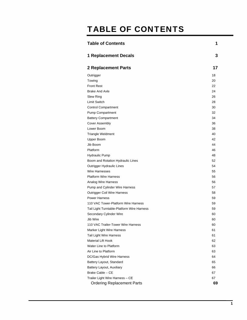
TABLE OF CONTENTS
Table of Contents 1
1 Replacement Decals 3
2 Replacement Parts 17
Outrigger 18
Towing 20
Front Rest 22
Brake And Axle 24
Slew Ring 26
Limit Switch 28
Control Compartment 30
Pump Compartment 32
Battery Compartment 34
Cover Assembly 36
Lower Boom 38
Triangle Weldment 40
Upper Boom 42
Jib Boom 44
Platform 46
Hydraulic Pump 48
Boom and Rotation Hydraulic Lines 52
Outrigger Hydraulic Lines 54
Wire Harnesses 55
Platform Wire Harness 56
Analog Wire Harness 56
Pump and Cylinder Wire Harness 57
Outrigger Coil Wire Harness 58
Power Harness 59
110 VAC Tower-Platform Wire Harness 59
Tail Light Turntable-Platform Wire Harness 59
Secondary Cylinder Wire 60
Jib Wire 60
110 VAC Trailer-Tower Wire Harness 60
Marker Light Wire Harness 61
Tail Light Wire Harness 61
Material Lift Hook 62
Water Line to Platform 63
Air Line to Platform 63
DC/Gas Hybrid Wire Harness 64
Battery Layout, Standard 65
Battery Layout, Auxiliary 66
Brake Cable – CE 67
Trailer Light Wire Harness – CE 67
Ordering Replacement Parts 69

2

3
1 REPLACEMENT DECALS
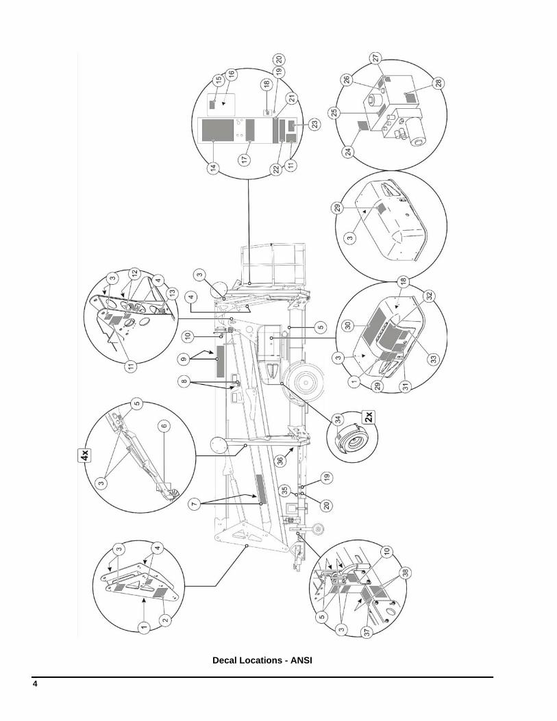
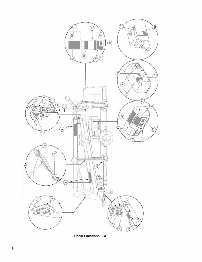
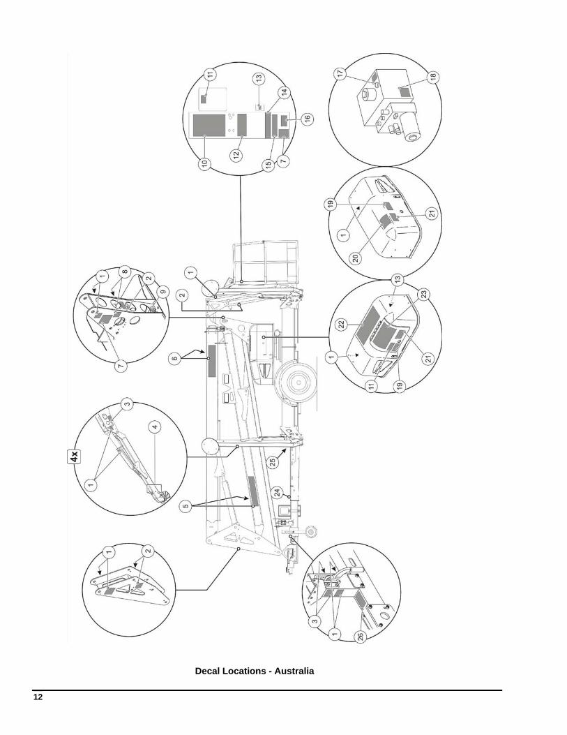
Decals contain information that is required for the safe and proper use of the aerial work platform. Decals should be considered necessary components of the machine and should be checked before each use to verify that they are correctly attached and legible.
Use the following guides to find the correct location of all decals.
4
Decal Locations - ANSI
1 — REPLACEMENT DECALS
5
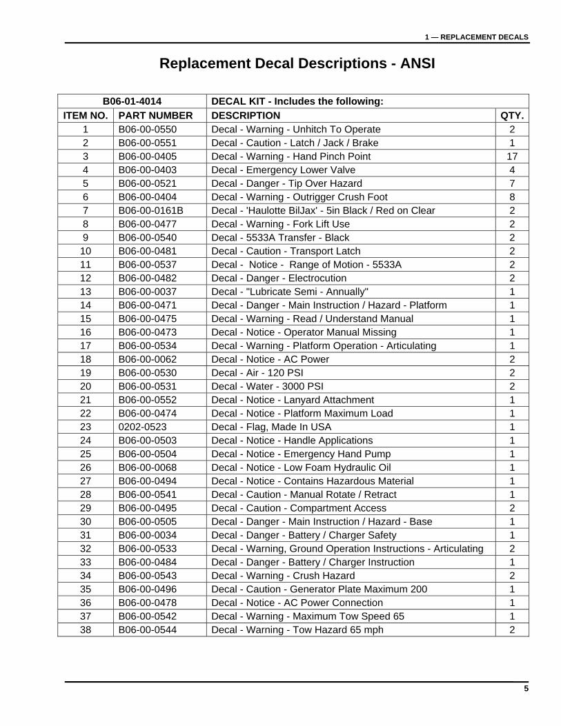
Replacement Decal Descriptions - ANSI
B06-01-4014 DECAL KIT - Includes the following:
ITEM NO. PART NUMBER DESCRIPTION QTY.1 B06-00-0550 Decal - Warning - Unhitch To Operate 2 2 B06-00-0551 Decal - Caution - Latch / Jack / Brake 1 3 B06-00-0405 Decal - Warning - Hand Pinch Point 17 4 B06-00-0403 Decal - Emergency Lower Valve 4 5 B06-00-0521 Decal - Danger - Tip Over Hazard 7 6 B06-00-0404 Decal - Warning - Outrigger Crush Foot 8 7 B06-00-0161B Decal - 'Haulotte BilJax' - 5in Black / Red on Clear 2 8 B06-00-0477 Decal - Warning - Fork Lift Use 2 9 B06-00-0540 Decal - 5533A Transfer - Black 2
10 B06-00-0481 Decal - Caution - Transport Latch 2 11 B06-00-0537 Decal - Notice - Range of Motion - 5533A 2 12 B06-00-0482 Decal - Danger - Electrocution 2 13 B06-00-0037 Decal - "Lubricate Semi - Annually" 1 14 B06-00-0471 Decal - Danger - Main Instruction / Hazard - Platform 1 15 B06-00-0475 Decal - Warning - Read / Understand Manual 1 16 B06-00-0473 Decal - Notice - Operator Manual Missing 1 17 B06-00-0534 Decal - Warning - Platform Operation - Articulating 1 18 B06-00-0062 Decal - Notice - AC Power 2 19 B06-00-0530 Decal - Air - 120 PSI 2 20 B06-00-0531 Decal - Water - 3000 PSI 2 21 B06-00-0552 Decal - Notice - Lanyard Attachment 1 22 B06-00-0474 Decal - Notice - Platform Maximum Load 1 23 0202-0523 Decal - Flag, Made In USA 1 24 B06-00-0503 Decal - Notice - Handle Applications 1 25 B06-00-0504 Decal - Notice - Emergency Hand Pump 1 26 B06-00-0068 Decal - Notice - Low Foam Hydraulic Oil 1 27 B06-00-0494 Decal - Notice - Contains Hazardous Material 1 28 B06-00-0541 Decal - Caution - Manual Rotate / Retract 1 29 B06-00-0495 Decal - Caution - Compartment Access 2 30 B06-00-0505 Decal - Danger - Main Instruction / Hazard - Base 1 31 B06-00-0034 Decal - Danger - Battery / Charger Safety 1 32 B06-00-0533 Decal - Warning, Ground Operation Instructions - Articulating 2 33 B06-00-0484 Decal - Danger - Battery / Charger Instruction 1 34 B06-00-0543 Decal - Warning - Crush Hazard 2 35 B06-00-0496 Decal - Caution - Generator Plate Maximum 200 1 36 B06-00-0478 Decal - Notice - AC Power Connection 1 37 B06-00-0542 Decal - Warning - Maximum Tow Speed 65 1 38 B06-00-0544 Decal - Warning - Tow Hazard 65 mph 2
6
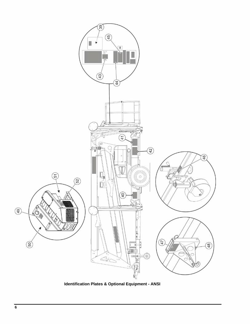
Identification Plates & Optional Equipment - ANSI
1 — REPLACEMENT DECALS
7
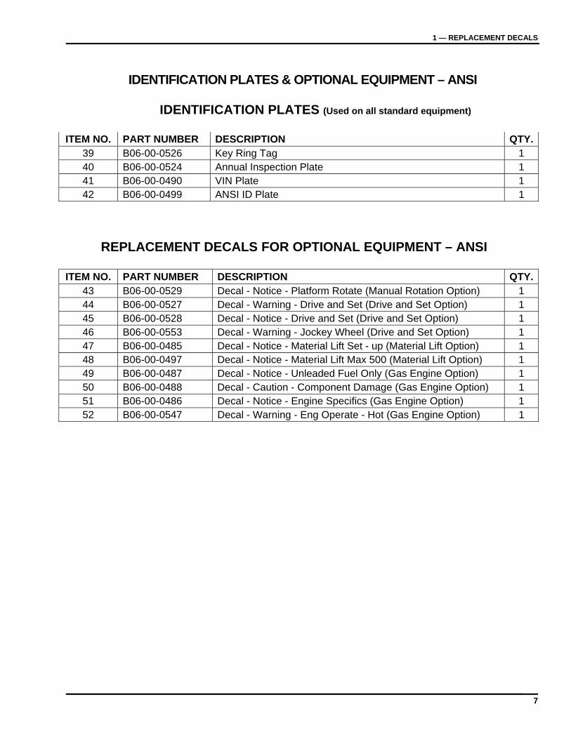
IDENTIFICATION PLATES & OPTIONAL EQUIPMENT – ANSI
IDENTIFICATION PLATES (Used on all standard equipment)
ITEM NO. PART NUMBER DESCRIPTION QTY.
39 B06-00-0526 Key Ring Tag 1 40 B06-00-0524 Annual Inspection Plate 1 41 B06-00-0490 VIN Plate 1 42 B06-00-0499 ANSI ID Plate 1
REPLACEMENT DECALS FOR OPTIONAL EQUIPMENT – ANSI
ITEM NO. PART NUMBER DESCRIPTION QTY.43 B06-00-0529 Decal - Notice - Platform Rotate (Manual Rotation Option) 1 44 B06-00-0527 Decal - Warning - Drive and Set (Drive and Set Option) 1 45 B06-00-0528 Decal - Notice - Drive and Set (Drive and Set Option) 1 46 B06-00-0553 Decal - Warning - Jockey Wheel (Drive and Set Option) 1 47 B06-00-0485 Decal - Notice - Material Lift Set - up (Material Lift Option) 1 48 B06-00-0497 Decal - Notice - Material Lift Max 500 (Material Lift Option) 1 49 B06-00-0487 Decal - Notice - Unleaded Fuel Only (Gas Engine Option) 1 50 B06-00-0488 Decal - Caution - Component Damage (Gas Engine Option) 1 51 B06-00-0486 Decal - Notice - Engine Specifics (Gas Engine Option) 1 52 B06-00-0547 Decal - Warning - Eng Operate - Hot (Gas Engine Option) 1
8
Decal Locations - CE
1 — REPLACEMENT DECALS
9
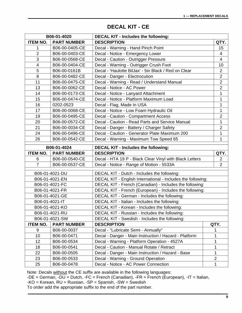
DECAL KIT - CE
B06-01-4020 DECAL KIT - Includes the following: ITEM NO. PART NUMBER DESCRIPTION QTY.
1 B06-00-0405-CE Decal - Warning - Hand Pinch Point 15 2 B06-00-0403-CE Decal - Notice - Emergency Lower 4 3 B06-00-0568-CE Decal - Caution - Outrigger Pressure 4 4 B06-00-0404-CE Decal - Warning - Outrigger Crush Foot 10 5 B06-00-0161B Decal - 'Haulotte BilJax' - 5in Black / Red on Clear 2 8 B06-00-0482-CE Decal - Danger - Electrocution 2
11 B06-00-0475-CE Decal - Warning - Read / Understand Manual 2 13 B06-00-0062-CE Decal - Notice - AC Power 2 14 B06-00-0173-CE Decal - Notice - Lanyard Attachment 1 15 B06-00-0474-CE Decal - Notice - Platform Maximum Load 1 16 0202-0523 Decal - Flag, Made In USA 1 17 B06-00-0068-CE Decal - Notice - Low Foam Hydraulic Oil 1 19 B06-00-0495-CE Decal - Caution - Compartment Access 2 20 B06-00-0572-CE Decal - Caution - Read Parts and Service Manual 1 21 B06-00-0034-CE Decal - Danger - Battery / Charger Safety 2 24 B06-00-0496-CE Decal - Caution - Generator Plate Maximum 200 1 26 B06-00-0542-CE Decal - Warning - Maximum Tow Speed 65 1
B06-01-4024 DECAL KIT - Includes the following: ITEM NO. PART NUMBER DESCRIPTION QTY.
6 B06-00-0540-CE Decal - HTA 19 P - Black Clear Vinyl with Black Letters 2 7 B06-00-0537-CE Decal - Notice - Range of Motion - 5533A 2
B06-01-4021-DU DECAL KIT - Dutch - Includes the following: B06-01-4021-EN DECAL KIT - English International - Includes the following: B06-01-4021-FC DECAL KIT - French (Canadian) - Includes the following: B06-01-4021-FR DECAL KIT - French (European) - Includes the following: B06-01-4021-GE DECAL KIT - German - Includes the following: B06-01-4021-IT DECAL KIT - Italian - Includes the following: B06-01-4021-KO DECAL KIT - Korean - Includes the following: B06-01-4021-RU DECAL KIT - Russian - Includes the following: B06-01-4021-SW DECAL KIT - Swedish - Includes the following: ITEM NO. PART NUMBER DESCRIPTION QTY.
9 B06-00-0037 Decal - "Lubricate Semi - Annually" 1 10 B06-00-0471 Decal - Danger - Main Instruction / Hazard - Platform 1 12 B06-00-0534 Decal - Warning - Platform Operation - 4527A 1 18 B06-00-0541 Decal - Caution - Manual Rotate / Retract 1 22 B06-00-0505 Decal - Danger - Main Instruction / Hazard - Base 1 23 B06-00-0533 Decal - Warning - Ground Operation 2 25 B06-00-0478 Decal - Notice - AC Power Connection 1
Note: Decals without the CE suffix are available in the following languages: -DE = German, -DU = Dutch, -FC = French (Canadian), -FR = French (European), -IT = Italian, -KO = Korean, RU = Russian, -SP = Spanish, -SW = Swedish To order add the appropriate suffix to the end of the part number.
10
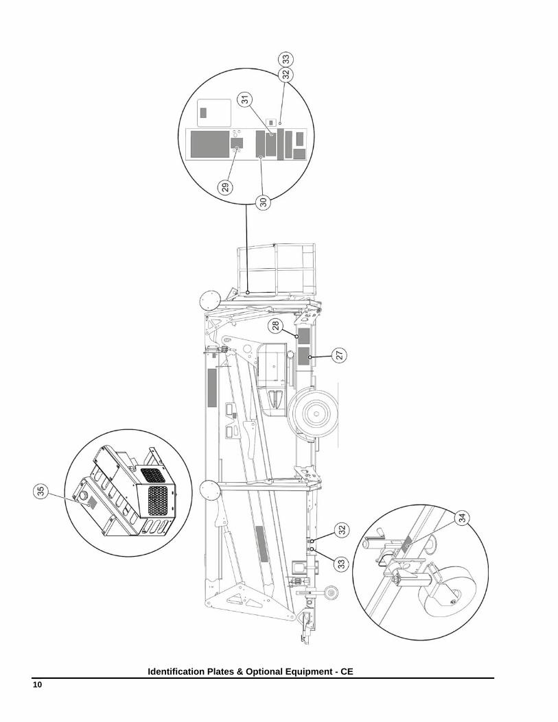
Identification Plates & Optional Equipment - CE
1 — REPLACEMENT DECALS
11
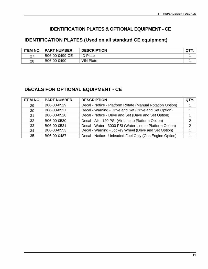
IDENTIFICATION PLATES & OPTIONAL EQUIPMENT - CE
IDENTIFICATION PLATES (Used on all standard CE equipment) ITEM NO. PART NUMBER DESCRIPTION QTY.
27 B06-00-0499-CE ID Plate 1
28 B06-00-0490 VIN Plate 1 DECALS FOR OPTIONAL EQUIPMENT - CE ITEM NO. PART NUMBER DESCRIPTION QTY.
29 B06-00-0529 Decal - Notice - Platform Rotate (Manual Rotation Option) 1 30 B06-00-0527 Decal - Warning - Drive and Set (Drive and Set Option) 1 31 B06-00-0528 Decal - Notice - Drive and Set (Drive and Set Option) 1 32 B06-00-0530 Decal - Air - 120 PSI (Air Line to Platform Option) 2 33 B06-00-0531 Decal - Water - 3000 PSI (Water Line to Platform Option) 2 34 B06-00-0553 Decal - Warning - Jockey Wheel (Drive and Set Option) 1 35 B06-00-0487 Decal - Notice - Unleaded Fuel Only (Gas Engine Option) 1
12
Decal Locations - Australia
1 — REPLACEMENT DECALS
13
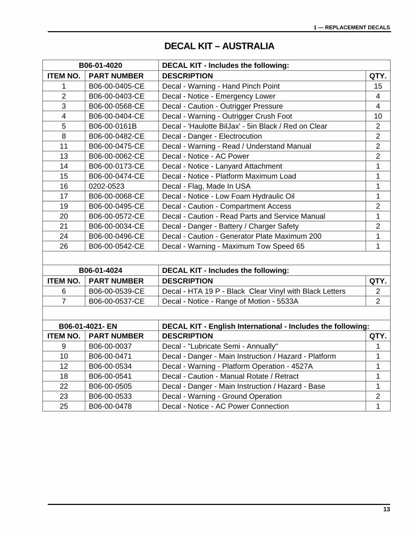
DECAL KIT – AUSTRALIA
B06-01-4020 DECAL KIT - Includes the following:
ITEM NO. PART NUMBER DESCRIPTION QTY.1 B06-00-0405-CE Decal - Warning - Hand Pinch Point 15 2 B06-00-0403-CE Decal - Notice - Emergency Lower 4 3 B06-00-0568-CE Decal - Caution - Outrigger Pressure 4 4 B06-00-0404-CE Decal - Warning - Outrigger Crush Foot 10 5 B06-00-0161B Decal - 'Haulotte BilJax' - 5in Black / Red on Clear 2 8 B06-00-0482-CE Decal - Danger - Electrocution 2
11 B06-00-0475-CE Decal - Warning - Read / Understand Manual 2 13 B06-00-0062-CE Decal - Notice - AC Power 2 14 B06-00-0173-CE Decal - Notice - Lanyard Attachment 1 15 B06-00-0474-CE Decal - Notice - Platform Maximum Load 1 16 0202-0523 Decal - Flag, Made In USA 1 17 B06-00-0068-CE Decal - Notice - Low Foam Hydraulic Oil 1 19 B06-00-0495-CE Decal - Caution - Compartment Access 2 20 B06-00-0572-CE Decal - Caution - Read Parts and Service Manual 1 21 B06-00-0034-CE Decal - Danger - Battery / Charger Safety 2 24 B06-00-0496-CE Decal - Caution - Generator Plate Maximum 200 1 26 B06-00-0542-CE Decal - Warning - Maximum Tow Speed 65 1
B06-01-4024 DECAL KIT - Includes the following:
ITEM NO. PART NUMBER DESCRIPTION QTY.6 B06-00-0539-CE Decal - HTA 19 P - Black Clear Vinyl with Black Letters 2 7 B06-00-0537-CE Decal - Notice - Range of Motion - 5533A 2
B06-01-4021- EN DECAL KIT - English International - Includes the following: ITEM NO. PART NUMBER DESCRIPTION QTY.
9 B06-00-0037 Decal - "Lubricate Semi - Annually" 1 10 B06-00-0471 Decal - Danger - Main Instruction / Hazard - Platform 1 12 B06-00-0534 Decal - Warning - Platform Operation - 4527A 1 18 B06-00-0541 Decal - Caution - Manual Rotate / Retract 1 22 B06-00-0505 Decal - Danger - Main Instruction / Hazard - Base 1 23 B06-00-0533 Decal - Warning - Ground Operation 2 25 B06-00-0478 Decal - Notice - AC Power Connection 1
14
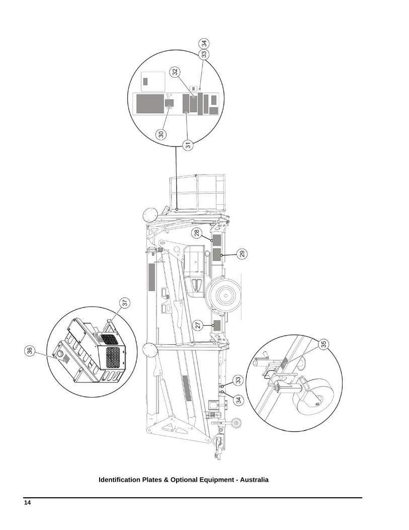
Identification Plates & Optional Equipment - Australia
1 — REPLACEMENT DECALS
15
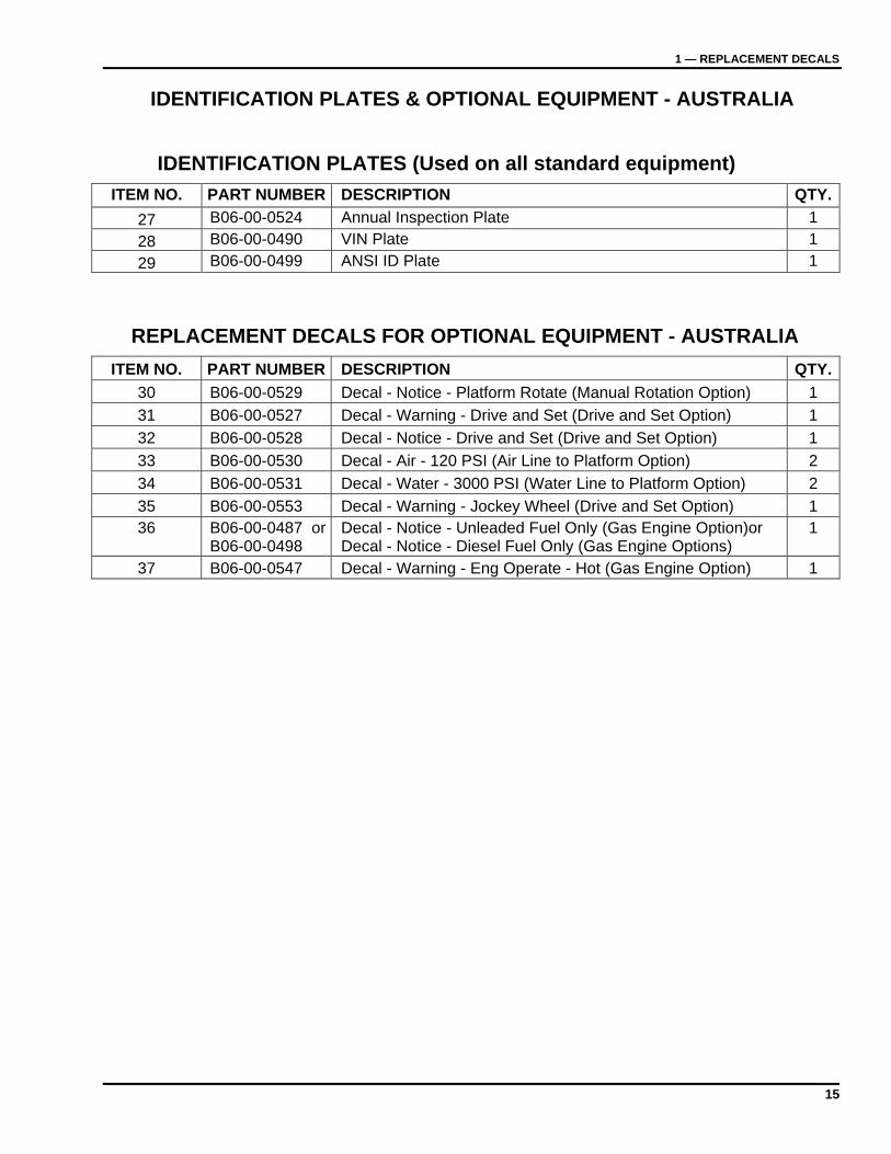
IDENTIFICATION PLATES & OPTIONAL EQUIPMENT - AUSTRALIA
IDENTIFICATION PLATES (Used on all standard equipment)
ITEM NO. PART NUMBER DESCRIPTION QTY.
27 B06-00-0524 Annual Inspection Plate 1
28 B06-00-0490 VIN Plate 1
29 B06-00-0499 ANSI ID Plate 1
REPLACEMENT DECALS FOR OPTIONAL EQUIPMENT - AUSTRALIA
ITEM NO. PART NUMBER DESCRIPTION QTY.
30 B06-00-0529 Decal - Notice - Platform Rotate (Manual Rotation Option) 1
31 B06-00-0527 Decal - Warning - Drive and Set (Drive and Set Option) 1
32 B06-00-0528 Decal - Notice - Drive and Set (Drive and Set Option) 1
33 B06-00-0530 Decal - Air - 120 PSI (Air Line to Platform Option) 2
34 B06-00-0531 Decal - Water - 3000 PSI (Water Line to Platform Option) 2
35 B06-00-0553 Decal - Warning - Jockey Wheel (Drive and Set Option) 1 36 B06-00-0487 or
B06-00-0498 Decal - Notice - Unleaded Fuel Only (Gas Engine Option)or Decal - Notice - Diesel Fuel Only (Gas Engine Options)
1
37 B06-00-0547 Decal - Warning - Eng Operate - Hot (Gas Engine Option) 1

16
17
2 REPLACEMENT PARTS
Use only parts manufactured and/or authorized by Haulotte Group | BilJax, Inc. when replacing damaged components. See page 69 for replacement part ordering information.
Only personnel properly trained and authorized to operate all equipment and familiar with all boom functions should attempt to repair or replace any part of the boom lift.
Always read, understand and obey all safety precautions included in this manual, as well as those precautions attached to the lift and dictated by federal, state and local regulations.
18
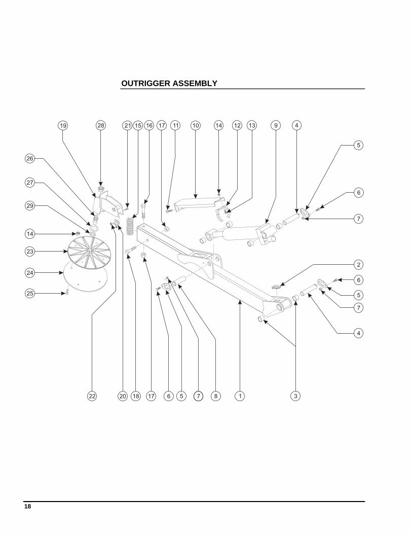
OUTRIGGER ASSEMBLY
1
2
3
4
5
6
8
1011 12 13141519
20
21
22
23
24
25
26
27
28 4
5
5
6
6
7
7
7
17
18
16
17
14
9
29
19
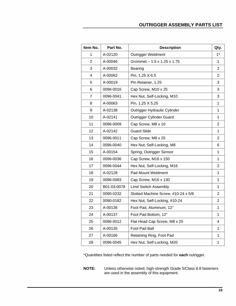
OUTRIGGER ASSEMBLY PARTS LIST
Item No. Part No. Description Qty.
1 A-02120 Outrigger Weldment 1*
2 A-00046 Grommet – 1.5 x 1.25 x 1.75 1
3 A-00032 Bearing 2
4 A-00062 Pin, 1.25 X 6.5 2
5 A-00019 Pin Retainer, 1.25 3
6 0096-0016 Cap Screw, M10 x 25 3
7 0096-0041 Hex Nut, Self-Locking, M10 3
8 A-00063 Pin, 1.25 X 5.25 1
9 A-02138 Outrigger Hydraulic Cylinder 1
10 A-02141 Outrigger Cylinder Guard 1
11 0096-0009 Cap Screw, M8 x 10 2
12 A-02142 Guard Slide 1
13 0096-0011 Cap Screw, M8 x 25 2
14 0096-0040 Hex Nut, Self-Locking, M8 6
15 A-00154 Spring, Outrigger Sensor 1
16 0096-0036 Cap Screw, M16 x 150 1
17 0096-0044 Hex Nut, Self-Locking, M16 2
18 A-02128 Pad Mount Weldment 1
19 0096-0083 Cap Screw, M16 x 130 1
20 B01-03-0078 Limit Switch Assembly 1
21 0090-0232 Slotted Machine Screw, #10-24 x 5/8 2
22 0090-0182 Hex Nut, Self-Locking, #10-24 2
23 A-00136 Foot Pad, Aluminum, 12” 1
24 A-00137 Foot Pad Bottom, 12” 1
25 0096-0012 Flat Head Cap Screw, M8 x 25 4
26 A-00135 Foot Pad Ball 1
27 A-00166 Retaining Ring, Foot Pad 1
28 0096-0045 Hex Nut, Self-Locking, M20 1
*Quantities listed reflect the number of parts needed for each outrigger.
NOTE: Unless otherwise noted, high-strength Grade 5/Class 8.8 fasteners are used in the assembly of this equipment.
20
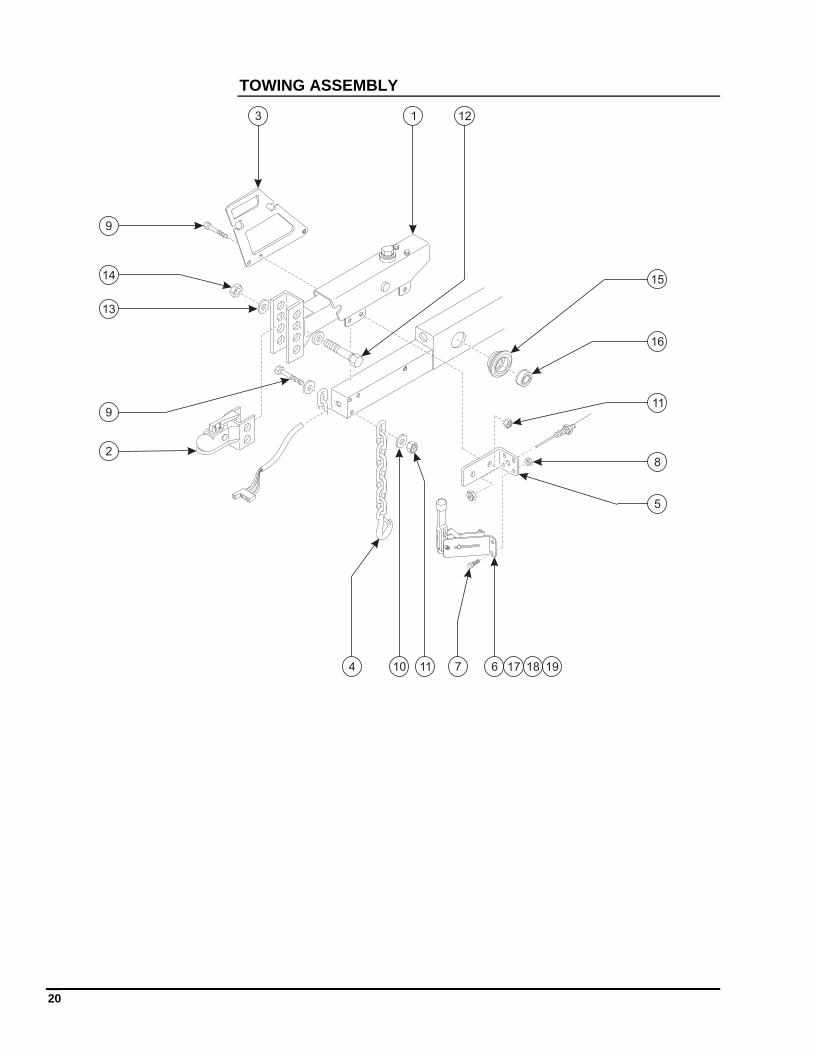
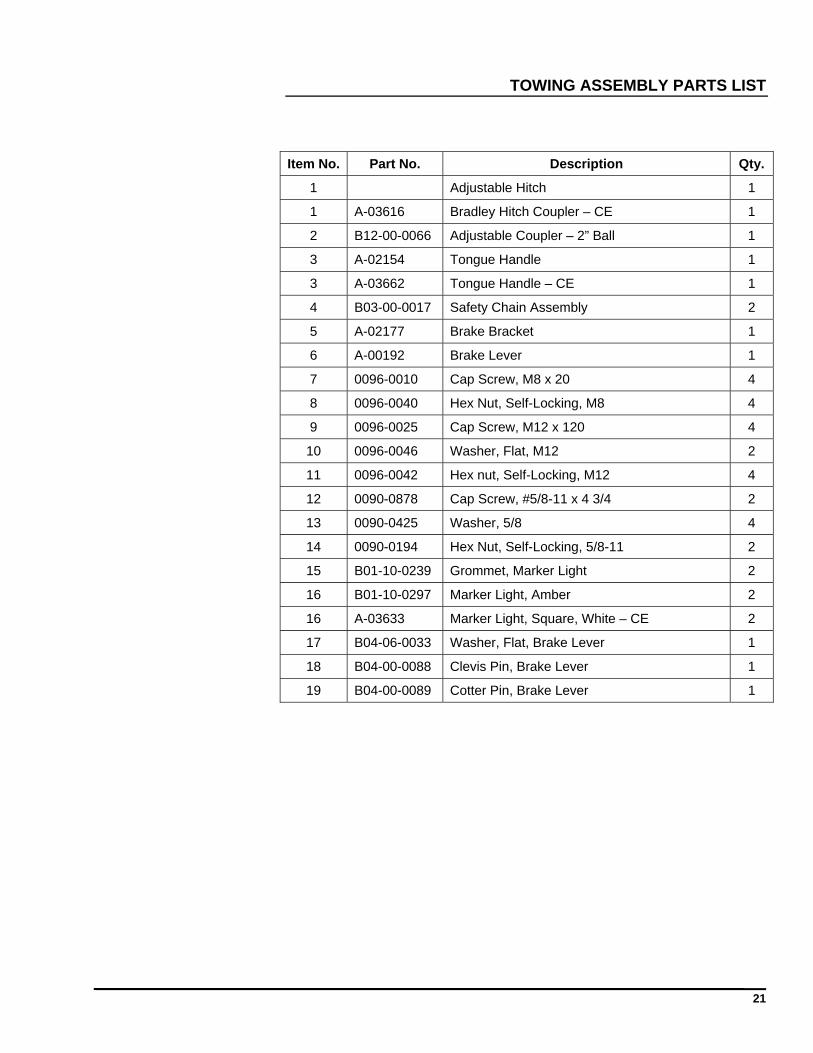
TOWING ASSEMBLY
1
2
3
4
5
67
8
9
10 11
12
13
14 15
16
11
9
17 18 19
21
TOWING ASSEMBLY PARTS LIST
Item No. Part No. Description Qty.
1 Adjustable Hitch 1
1 A-03616 Bradley Hitch Coupler – CE 1
2 B12-00-0066 Adjustable Coupler – 2” Ball 1
3 A-02154 Tongue Handle 1
3 A-03662 Tongue Handle – CE 1
4 B03-00-0017 Safety Chain Assembly 2
5 A-02177 Brake Bracket 1
6 A-00192 Brake Lever 1
7 0096-0010 Cap Screw, M8 x 20 4
8 0096-0040 Hex Nut, Self-Locking, M8 4
9 0096-0025 Cap Screw, M12 x 120 4
10 0096-0046 Washer, Flat, M12 2
11 0096-0042 Hex nut, Self-Locking, M12 4
12 0090-0878 Cap Screw, #5/8-11 x 4 3/4 2
13 0090-0425 Washer, 5/8 4
14 0090-0194 Hex Nut, Self-Locking, 5/8-11 2
15 B01-10-0239 Grommet, Marker Light 2
16 B01-10-0297 Marker Light, Amber 2
16 A-03633 Marker Light, Square, White – CE 2
17 B04-06-0033 Washer, Flat, Brake Lever 1
18 B04-00-0088 Clevis Pin, Brake Lever 1
19 B04-00-0089 Cotter Pin, Brake Lever 1
22
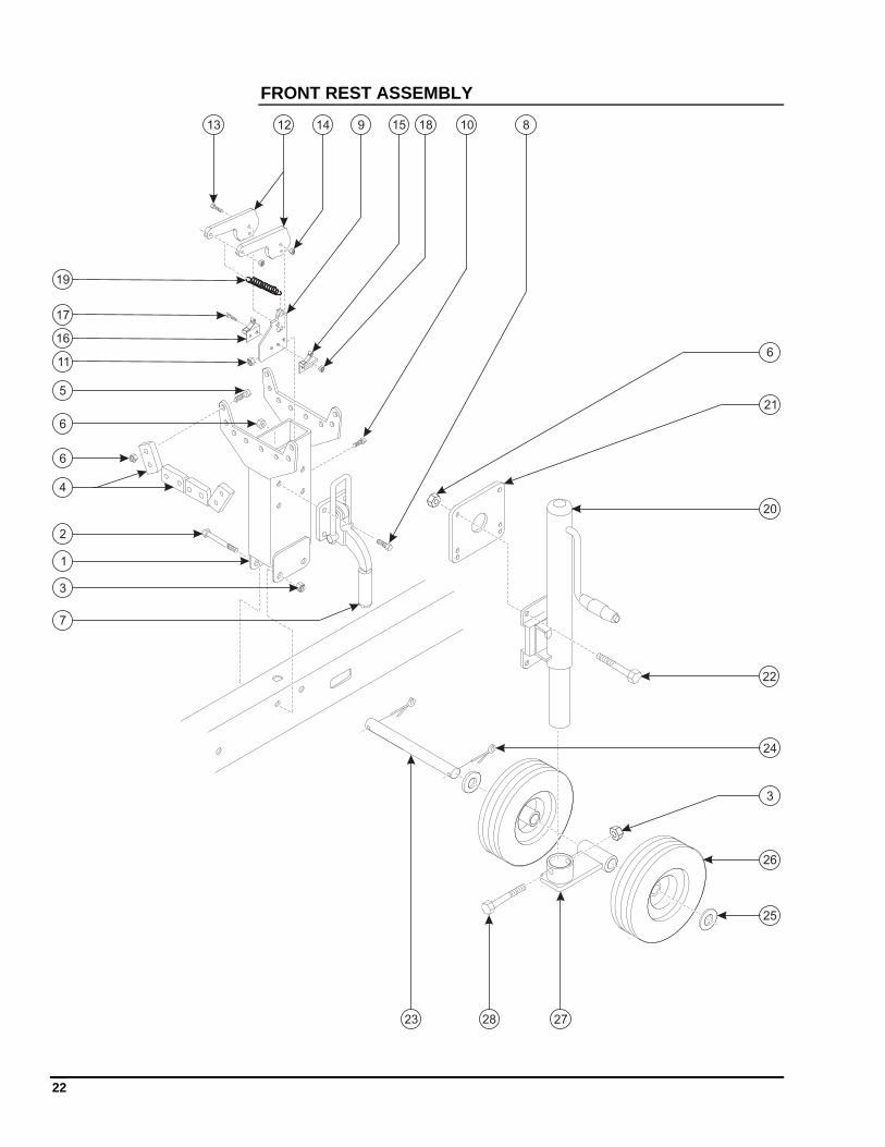
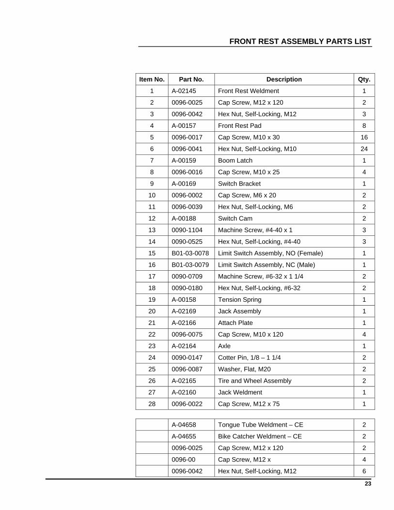
FRONT REST ASSEMBLY
1
2
3
4
5
10 89
6
7
11
1213 14 15
16
17
18
19
20
21
22
24
23
25
6
6
26
2728
3
23
FRONT REST ASSEMBLY PARTS LIST
Item No. Part No. Description Qty.
1 A-02145 Front Rest Weldment 1
2 0096-0025 Cap Screw, M12 x 120 2
3 0096-0042 Hex Nut, Self-Locking, M12 3
4 A-00157 Front Rest Pad 8
5 0096-0017 Cap Screw, M10 x 30 16
6 0096-0041 Hex Nut, Self-Locking, M10 24
7 A-00159 Boom Latch 1
8 0096-0016 Cap Screw, M10 x 25 4
9 A-00169 Switch Bracket 1
10 0096-0002 Cap Screw, M6 x 20 2
11 0096-0039 Hex Nut, Self-Locking, M6 2
12 A-00188 Switch Cam 2
13 0090-1104 Machine Screw, #4-40 x 1 3
14 0090-0525 Hex Nut, Self-Locking, #4-40 3
15 B01-03-0078 Limit Switch Assembly, NO (Female) 1
16 B01-03-0079 Limit Switch Assembly, NC (Male) 1
17 0090-0709 Machine Screw, #6-32 x 1 1/4 2
18 0090-0180 Hex Nut, Self-Locking, #6-32 2
19 A-00158 Tension Spring 1
20 A-02169 Jack Assembly 1
21 A-02166 Attach Plate 1
22 0096-0075 Cap Screw, M10 x 120 4
23 A-02164 Axle 1
24 0090-0147 Cotter Pin, 1/8 – 1 1/4 2
25 0096-0087 Washer, Flat, M20 2
26 A-02165 Tire and Wheel Assembly 2
27 A-02160 Jack Weldment 1
28 0096-0022 Cap Screw, M12 x 75 1
A-04658 Tongue Tube Weldment – CE 2
A-04655 Bike Catcher Weldment – CE 2
0096-0025 Cap Screw, M12 x 120 2
0096-00 Cap Screw, M12 x 4
0096-0042 Hex Nut, Self-Locking, M12 6
24
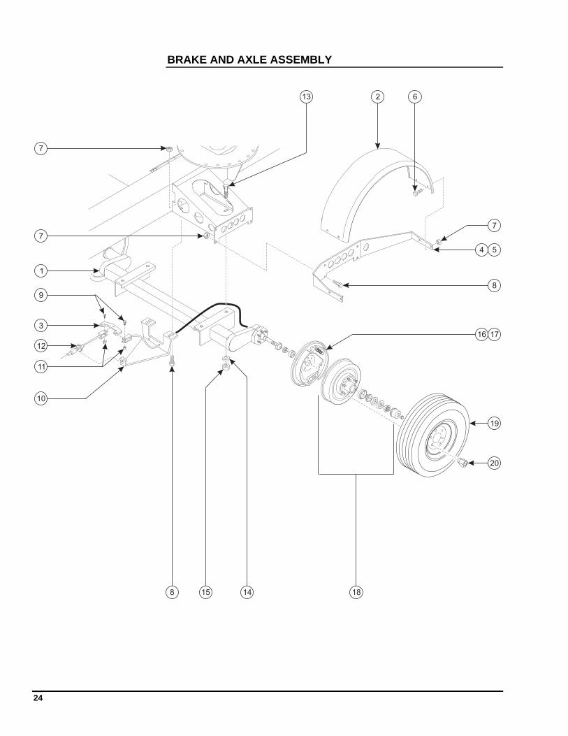
BRAKE AND AXLE ASSEMBLY
1
2
3
4 5
6
7
8
9
10
11
12
13
1415
16 17
18
7
8
7
19
20
25
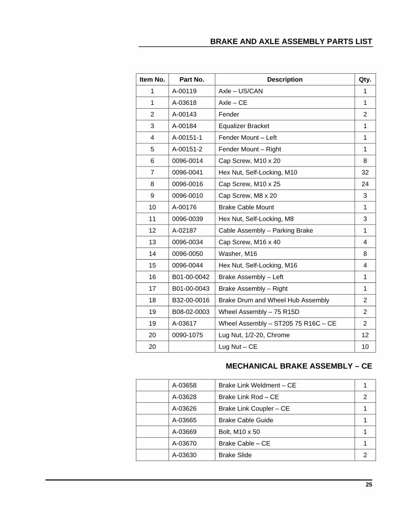
BRAKE AND AXLE ASSEMBLY PARTS LIST
Item No. Part No. Description Qty.
1 A-00119 Axle – US/CAN 1
1 A-03618 Axle – CE 1
2 A-00143 Fender 2
3 A-00184 Equalizer Bracket 1
4 A-00151-1 Fender Mount – Left 1
5 A-00151-2 Fender Mount – Right 1
6 0096-0014 Cap Screw, M10 x 20 8
7 0096-0041 Hex Nut, Self-Locking, M10 32
8 0096-0016 Cap Screw, M10 x 25 24
9 0096-0010 Cap Screw, M8 x 20 3
10 A-00176 Brake Cable Mount 1
11 0096-0039 Hex Nut, Self-Locking, M8 3
12 A-02187 Cable Assembly – Parking Brake 1
13 0096-0034 Cap Screw, M16 x 40 4
14 0096-0050 Washer, M16 8
15 0096-0044 Hex Nut, Self-Locking, M16 4
16 B01-00-0042 Brake Assembly – Left 1
17 B01-00-0043 Brake Assembly – Right 1
18 B32-00-0016 Brake Drum and Wheel Hub Assembly 2
19 B08-02-0003 Wheel Assembly – 75 R15D 2
19 A-03617 Wheel Assembly – ST205 75 R16C – CE 2
20 0090-1075 Lug Nut, 1/2-20, Chrome 12
20 Lug Nut – CE 10
MECHANICAL BRAKE ASSEMBLY – CE
A-03658 Brake Link Weldment – CE 1
A-03628 Brake Link Rod – CE 2
A-03626 Brake Link Coupler – CE 1
A-03665 Brake Cable Guide 1
A-03669 Bolt, M10 x 50 1
A-03670 Brake Cable – CE 1
A-03630 Brake Slide 2
26
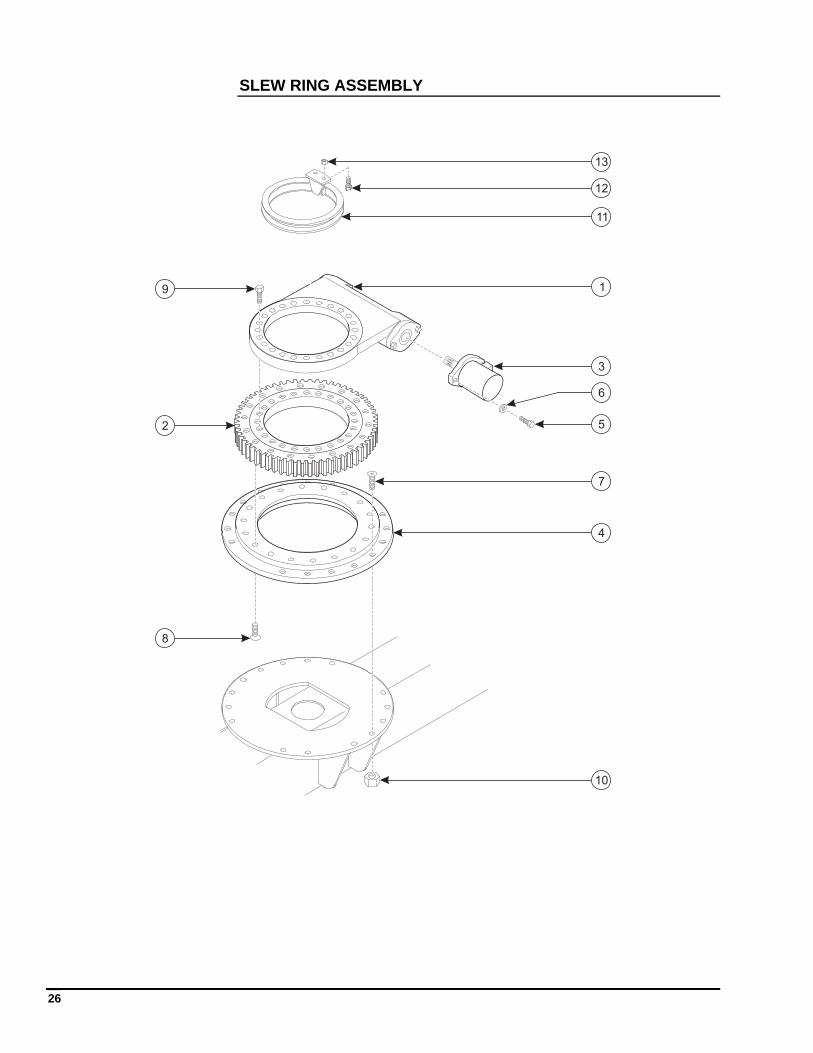
SLEW RING ASSEMBLY
3
1
2 5
6
7
8
9
10
11
12
13
4
27
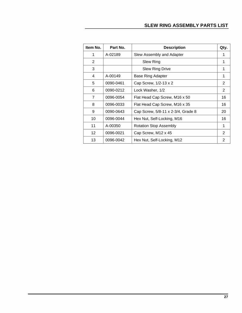
SLEW RING ASSEMBLY PARTS LIST
Item No. Part No. Description Qty.
1 A-02189 Slew Assembly and Adapter 1
2 Slew Ring 1
3 Slew Ring Drive 1
4 A-00149 Base Ring Adapter 1
5 0090-0461 Cap Screw, 1/2-13 x 2 2
6 0090-0212 Lock Washer, 1/2 2
7 0096-0054 Flat Head Cap Screw, M16 x 50 16
8 0096-0033 Flat Head Cap Screw, M16 x 35 16
9 0090-0643 Cap Screw, 5/8-11 x 2-3/4, Grade 8 20
10 0096-0044 Hex Nut, Self-Locking, M16 16
11 A-00350 Rotation Stop Assembly 1
12 0096-0021 Cap Screw, M12 x 45 2
13 0096-0042 Hex Nut, Self-Locking, M12 2
28
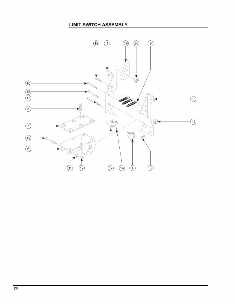
LIMIT SWITCH ASSEMBLY
1
2
345
6
7
8
9
10
11
12
13
14
15
11 17
18 19 20
29
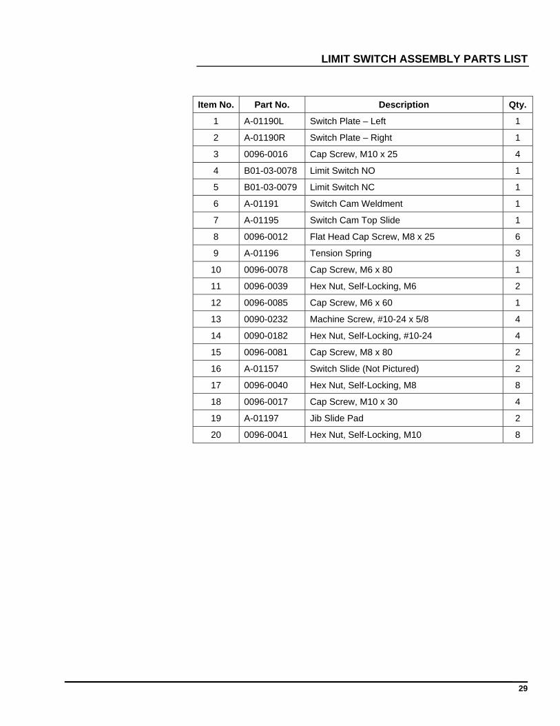
LIMIT SWITCH ASSEMBLY PARTS LIST
Item No. Part No. Description Qty.
1 A-01190L Switch Plate – Left 1
2 A-01190R Switch Plate – Right 1
3 0096-0016 Cap Screw, M10 x 25 4
4 B01-03-0078 Limit Switch NO 1
5 B01-03-0079 Limit Switch NC 1
6 A-01191 Switch Cam Weldment 1
7 A-01195 Switch Cam Top Slide 1
8 0096-0012 Flat Head Cap Screw, M8 x 25 6
9 A-01196 Tension Spring 3
10 0096-0078 Cap Screw, M6 x 80 1
11 0096-0039 Hex Nut, Self-Locking, M6 2
12 0096-0085 Cap Screw, M6 x 60 1
13 0090-0232 Machine Screw, #10-24 x 5/8 4
14 0090-0182 Hex Nut, Self-Locking, #10-24 4
15 0096-0081 Cap Screw, M8 x 80 2
16 A-01157 Switch Slide (Not Pictured) 2
17 0096-0040 Hex Nut, Self-Locking, M8 8
18 0096-0017 Cap Screw, M10 x 30 4
19 A-01197 Jib Slide Pad 2
20 0096-0041 Hex Nut, Self-Locking, M10 8
30
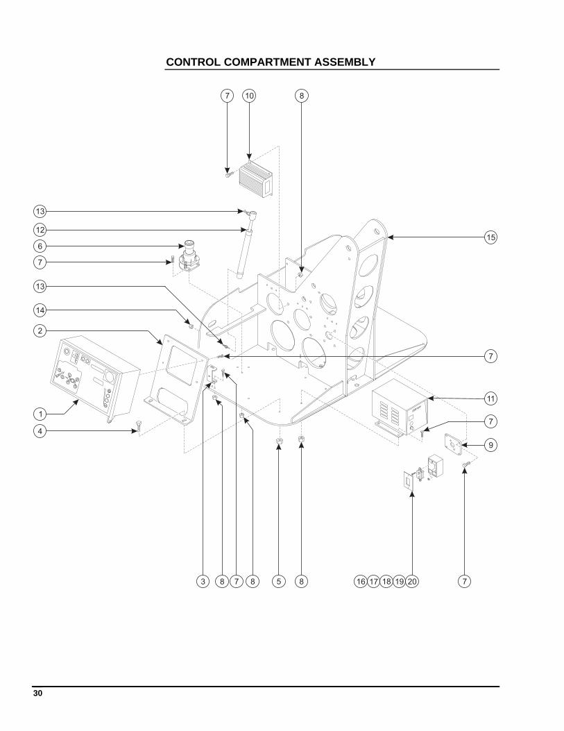
CONTROL COMPARTMENT ASSEMBLY
6
9
10
11
12
13
15
13
17 18 19 2016
7
7
7 8
1
2
3
4
578
14
8 8
7
7
31
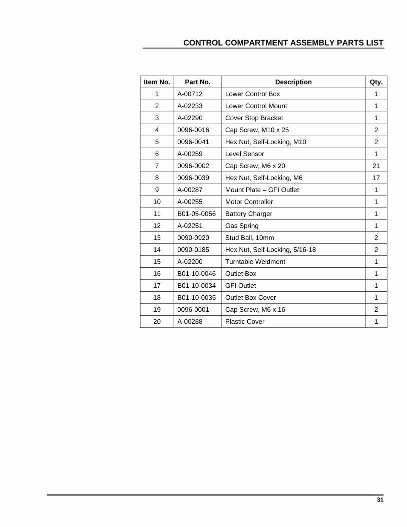
CONTROL COMPARTMENT ASSEMBLY PARTS LIST
Item No. Part No. Description Qty.
1 A-00712 Lower Control Box 1
2 A-02233 Lower Control Mount 1
3 A-02290 Cover Stop Bracket 1
4 0096-0016 Cap Screw, M10 x 25 2
5 0096-0041 Hex Nut, Self-Locking, M10 2
6 A-00259 Level Sensor 1
7 0096-0002 Cap Screw, M6 x 20 21
8 0096-0039 Hex Nut, Self-Locking, M6 17
9 A-00287 Mount Plate – GFI Outlet 1
10 A-00255 Motor Controller 1
11 B01-05-0056 Battery Charger 1
12 A-02251 Gas Spring 1
13 0090-0920 Stud Ball, 10mm 2
14 0090-0185 Hex Nut, Self-Locking, 5/16-18 2
15 A-02200 Turntable Weldment 1
16 B01-10-0046 Outlet Box 1
17 B01-10-0034 GFI Outlet 1
18 B01-10-0035 Outlet Box Cover 1
19 0096-0001 Cap Screw, M6 x 16 2
20 A-00288 Plastic Cover 1
32
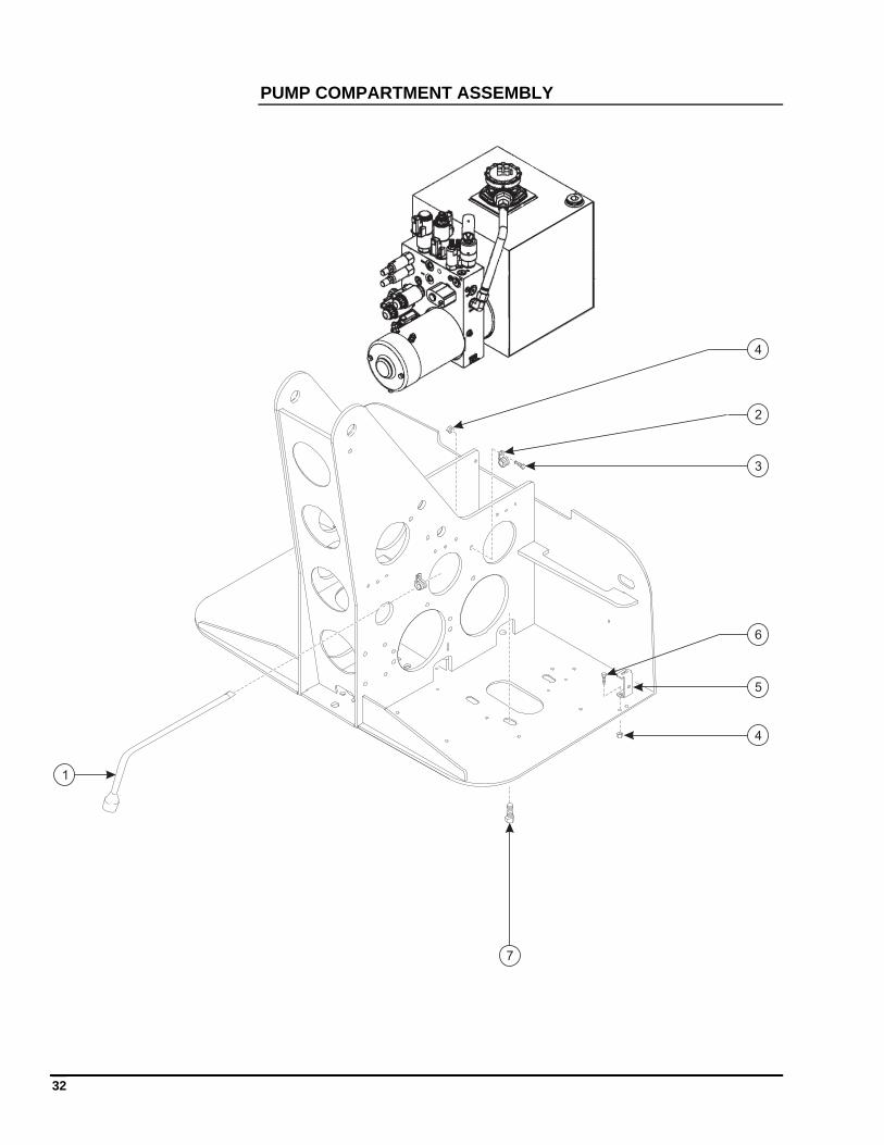
PUMP COMPARTMENT ASSEMBLY
1
2
3
4
5
6
7
4
33
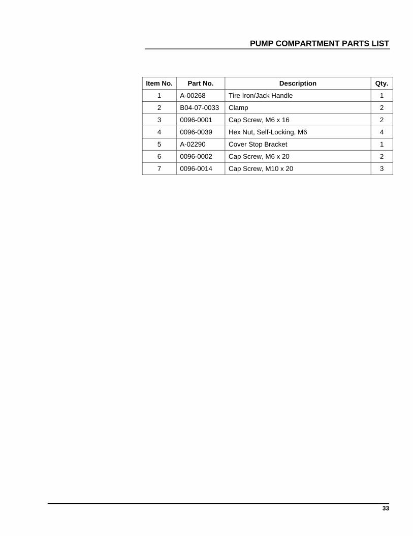
PUMP COMPARTMENT PARTS LIST
Item No. Part No. Description Qty.
1 A-00268 Tire Iron/Jack Handle 1
2 B04-07-0033 Clamp 2
3 0096-0001 Cap Screw, M6 x 16 2
4 0096-0039 Hex Nut, Self-Locking, M6 4
5 A-02290 Cover Stop Bracket 1
6 0096-0002 Cap Screw, M6 x 20 2
7 0096-0014 Cap Screw, M10 x 20 3
34
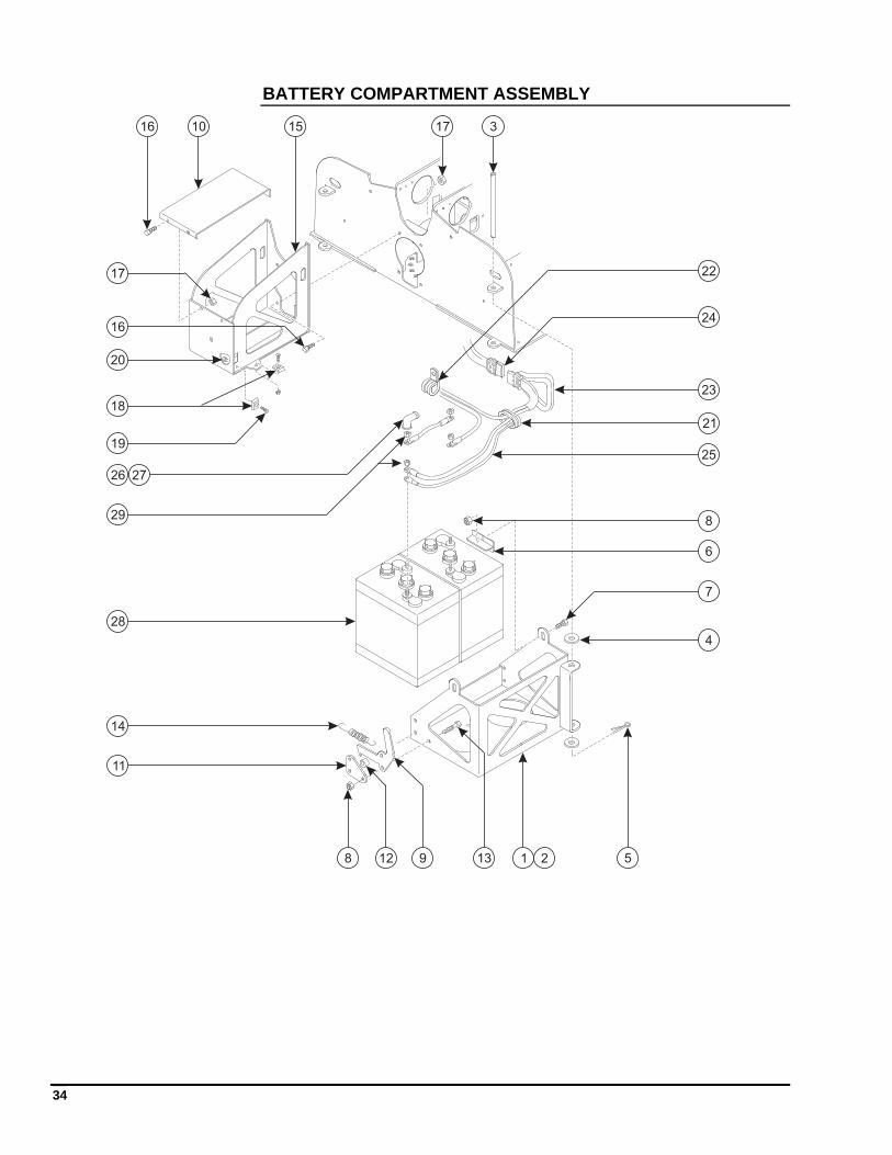
BATTERY COMPARTMENT ASSEMBLY
1
3
4
5
6
7
11
14
17
28 9
10
1312
8
22
24
23
21
25
20
26 27
29
28
16
16
17
15
19
18
35
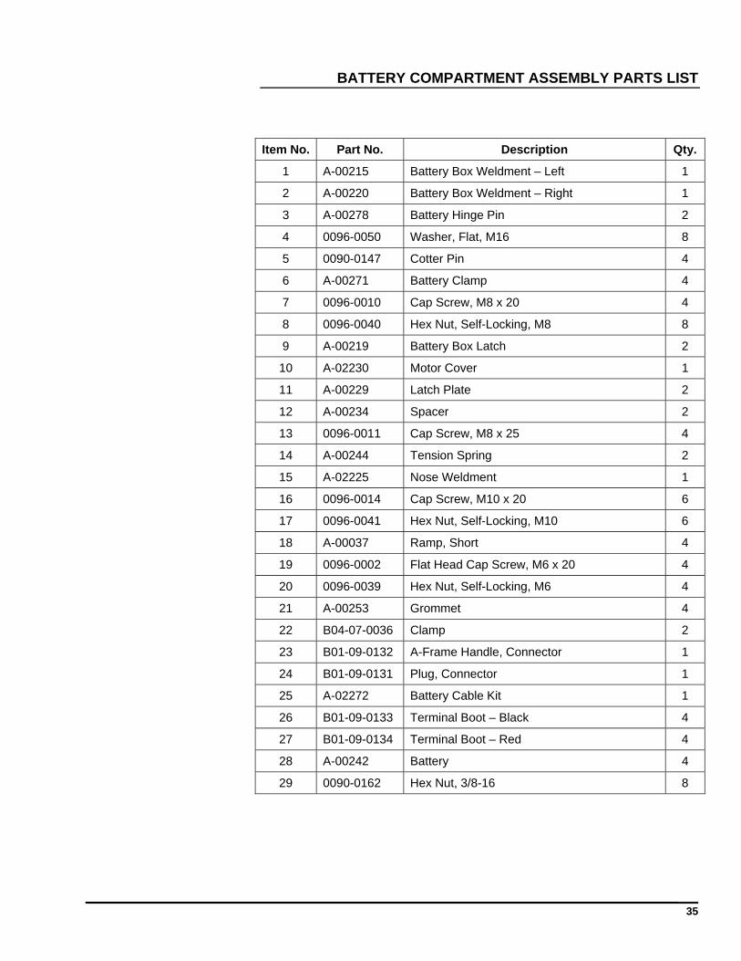
BATTERY COMPARTMENT ASSEMBLY PARTS LIST
Item No. Part No. Description Qty.
1 A-00215 Battery Box Weldment – Left 1
2 A-00220 Battery Box Weldment – Right 1
3 A-00278 Battery Hinge Pin 2
4 0096-0050 Washer, Flat, M16 8
5 0090-0147 Cotter Pin 4
6 A-00271 Battery Clamp 4
7 0096-0010 Cap Screw, M8 x 20 4
8 0096-0040 Hex Nut, Self-Locking, M8 8
9 A-00219 Battery Box Latch 2
10 A-02230 Motor Cover 1
11 A-00229 Latch Plate 2
12 A-00234 Spacer 2
13 0096-0011 Cap Screw, M8 x 25 4
14 A-00244 Tension Spring 2
15 A-02225 Nose Weldment 1
16 0096-0014 Cap Screw, M10 x 20 6
17 0096-0041 Hex Nut, Self-Locking, M10 6
18 A-00037 Ramp, Short 4
19 0096-0002 Flat Head Cap Screw, M6 x 20 4
20 0096-0039 Hex Nut, Self-Locking, M6 4
21 A-00253 Grommet 4
22 B04-07-0036 Clamp 2
23 B01-09-0132 A-Frame Handle, Connector 1
24 B01-09-0131 Plug, Connector 1
25 A-02272 Battery Cable Kit 1
26 B01-09-0133 Terminal Boot – Black 4
27 B01-09-0134 Terminal Boot – Red 4
28 A-00242 Battery 4
29 0090-0162 Hex Nut, 3/8-16 8
36
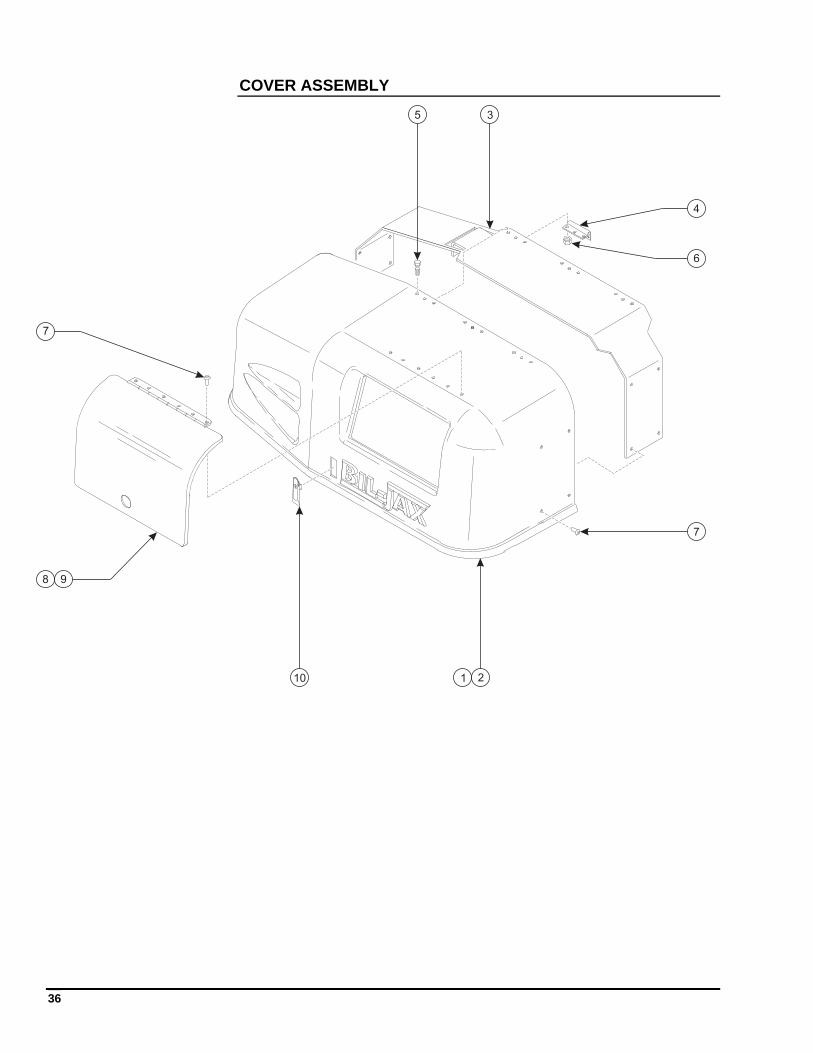
COVER ASSEMBLY
1 2
3
4
5
6
7
8 9
10
7
37
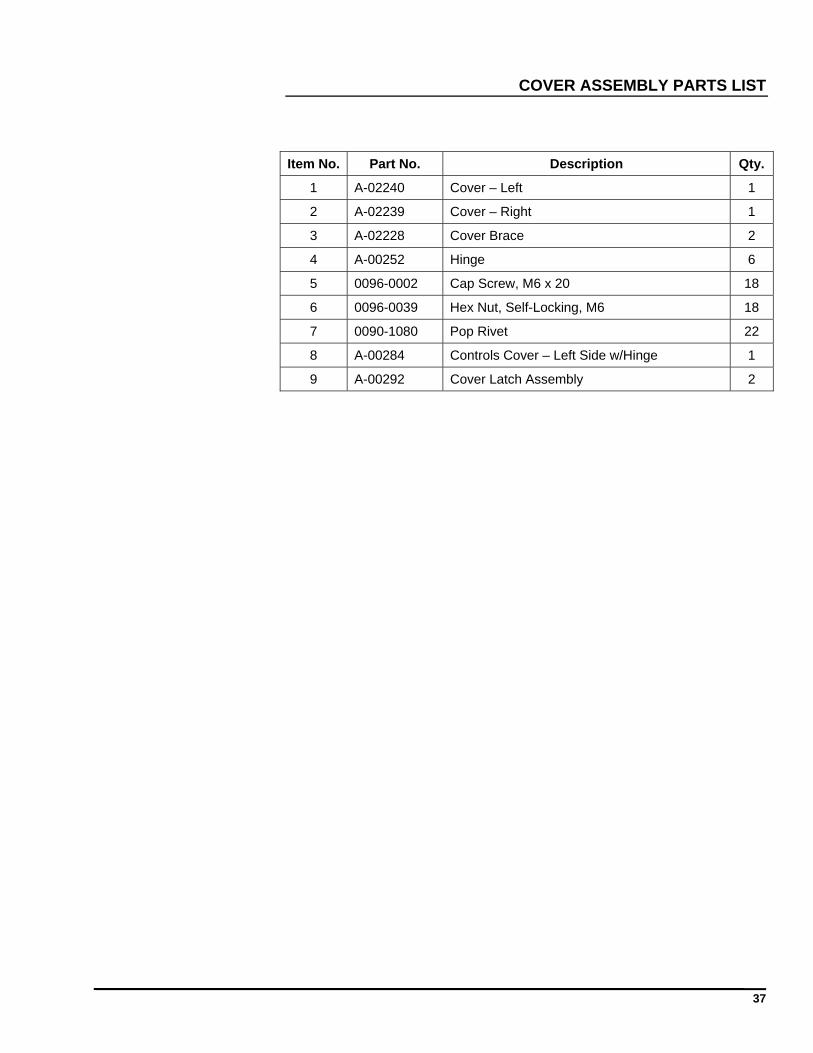
COVER ASSEMBLY PARTS LIST
Item No. Part No. Description Qty.
1 A-02240 Cover – Left 1
2 A-02239 Cover – Right 1
3 A-02228 Cover Brace 2
4 A-00252 Hinge 6
5 0096-0002 Cap Screw, M6 x 20 18
6 0096-0039 Hex Nut, Self-Locking, M6 18
7 0090-1080 Pop Rivet 22
8 A-00284 Controls Cover – Left Side w/Hinge 1
9 A-00292 Cover Latch Assembly 2
38
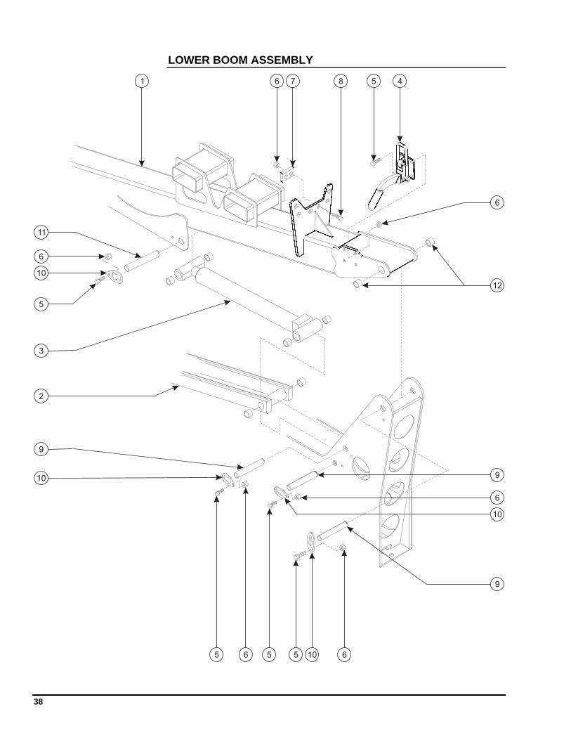
LOWER BOOM ASSEMBLY
1
2
3
4
5
6
7 8
9
10
11
5
6
6
12
6 6
5
5 5
6
10
10
10
9
9
39
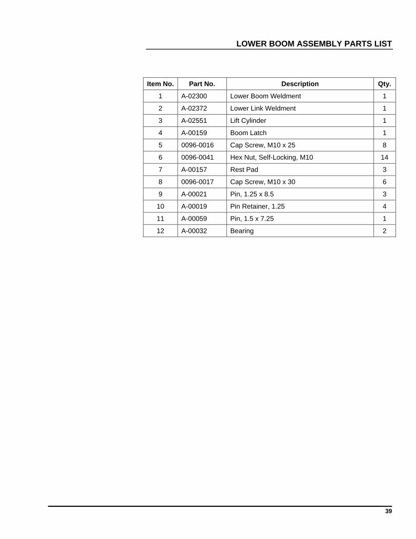
LOWER BOOM ASSEMBLY PARTS LIST
Item No. Part No. Description Qty.
1 A-02300 Lower Boom Weldment 1
2 A-02372 Lower Link Weldment 1
3 A-02551 Lift Cylinder 1
4 A-00159 Boom Latch 1
5 0096-0016 Cap Screw, M10 x 25 8
6 0096-0041 Hex Nut, Self-Locking, M10 14
7 A-00157 Rest Pad 3
8 0096-0017 Cap Screw, M10 x 30 6
9 A-00021 Pin, 1.25 x 8.5 3
10 A-00019 Pin Retainer, 1.25 4
11 A-00059 Pin, 1.5 x 7.25 1
12 A-00032 Bearing 2
40
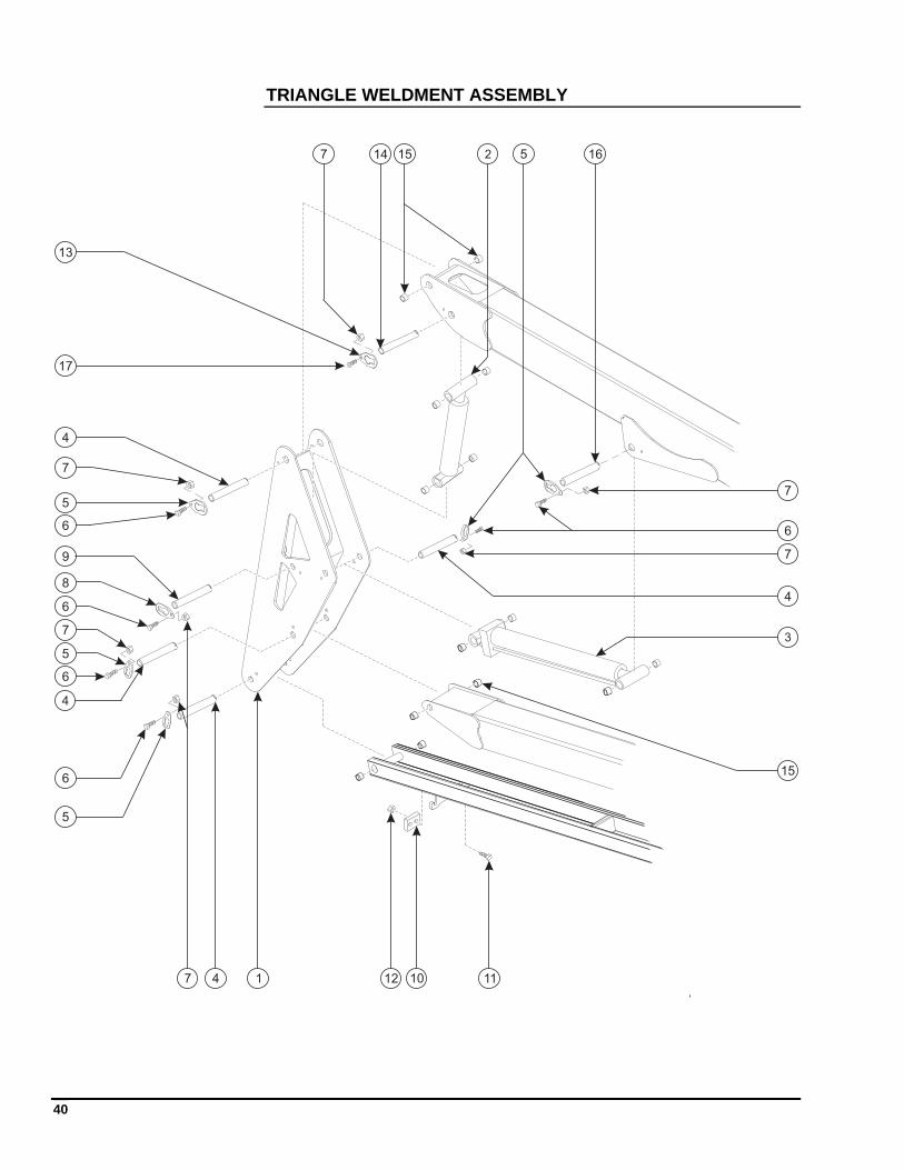
TRIANGLE WELDMENT ASSEMBLY
1
2
3
4
6
79
10 11
4
5
5
6
6
6
7
127
7
8
7
6
147 15 16
15
13
17
5
5
4
4
41
TRIANGLE WELDMENT ASSEMBLY PARTS LIST
Item No. Part No. Description Qty.
1 A-02320 Triangle Weldment 1
2 A-01552 Master Cylinder 1
3 A-02551 Lift Cylinder 1
4 A-00021 Pin, 1.25 x 8.5 4
5 A-00019 Pin Retainer, 1.25 7
6 0096-0016 Cap Screw, M10 x 25 8
7 0096-0041 Hex Nut, Self-Locking, M10 9
8 A-00018 Pin Retainer, 1.0 1
9 A-00049 Pin, 1.0 x 8.5 1
10 A-00537 Switch Block 1
11 0096-0049 Cap Screw, M8 x 45 2
12 0096-0040 Hex Nut, Self-Locking, M8 2
13 A-00054 Pin Retainer, 1.0 FH 1
14 A-00051 Pin, 1.0 x 7.0, DB 1
15 A-00032 Bearing 4
16 A-00059 Pin, 1.25 x 7.25 1
17 0096-0091 Flat Head Cap Screw, M10 x 25 1
42
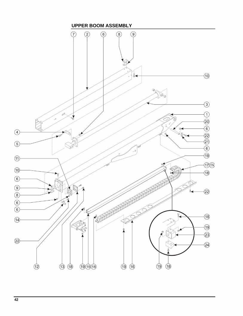
UPPER BOOM ASSEMBLY
43
UPPER BOOM ASSEMBLY PARTS LIST
Item No. Part No. Description Qty.
1 A-02502 Upper Boom Weldment 1
2 A-02510 Telescopic Boom Tube 1
3 A-02550 Extension Cylinder 1
4 A-00535 Slider 2
5 0096-0017 Cap Screw, M10 x 30 4
6 0096-0041 Hex Nut, Self-Locking, M10 16
7 0096-0033 Flat Head Cap Screw, M16 x 35 4
8 A-00533 Wear Pad 12
9 A-00534 Wear Pad Shim 8
10 0096-0013 UHMW Bolts, M10 x 15 24
11 A-00532 Tube Slider 1
12 A-00529 Tube Slider Back 1
13 0096-0018 Cap Screw, M10 x 40 4
14 A-01554 Boom Latch Hook 1
15 A-02531 Cable Track Tube 1
16 A-02536 Cable Track Tray 1
17
17A
A-02530
A-02520
Cable Track, Dual Piece Mounting, Both Ends (Prior to June 2010)
Cable Track, Single Piece Mounting, Both Ends (June 2010 onwards). Also uses: 0096-0012 M8 x 25 Flat Head Cap Screw (Qty of 2) to attach to Item 16
1
18 0096-0010 Cap Screw, M8 x 20 (Qty used decreases by 6 when 17A is used)
18
19 0096-0040 Hex Nut, Self-Locking, M8 (Qty used decreases by 4 when 17A is used)
18
20 A-00035 Pin, 0.75 x 6.5 1
21 A-00034 Pin Retainer, 0.75 1
22 0096-0016 Cap Screw, M10 x 25 8
23 A-00538 Cable Support Tube 1
24 A-00539 Cable Slide Block 1
44
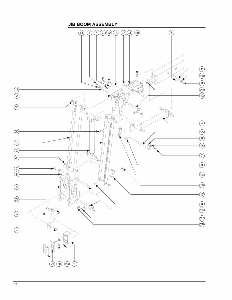
JIB BOOM ASSEMBLY
2
3
5
6
7 8
1
7 12 13
11
8
10
9
13
4
15
8
14
7
16
18
17
15
7
22
21 23 1920
2425
27
26
15
8
14
7
8
8
28
29
30
31
31
45
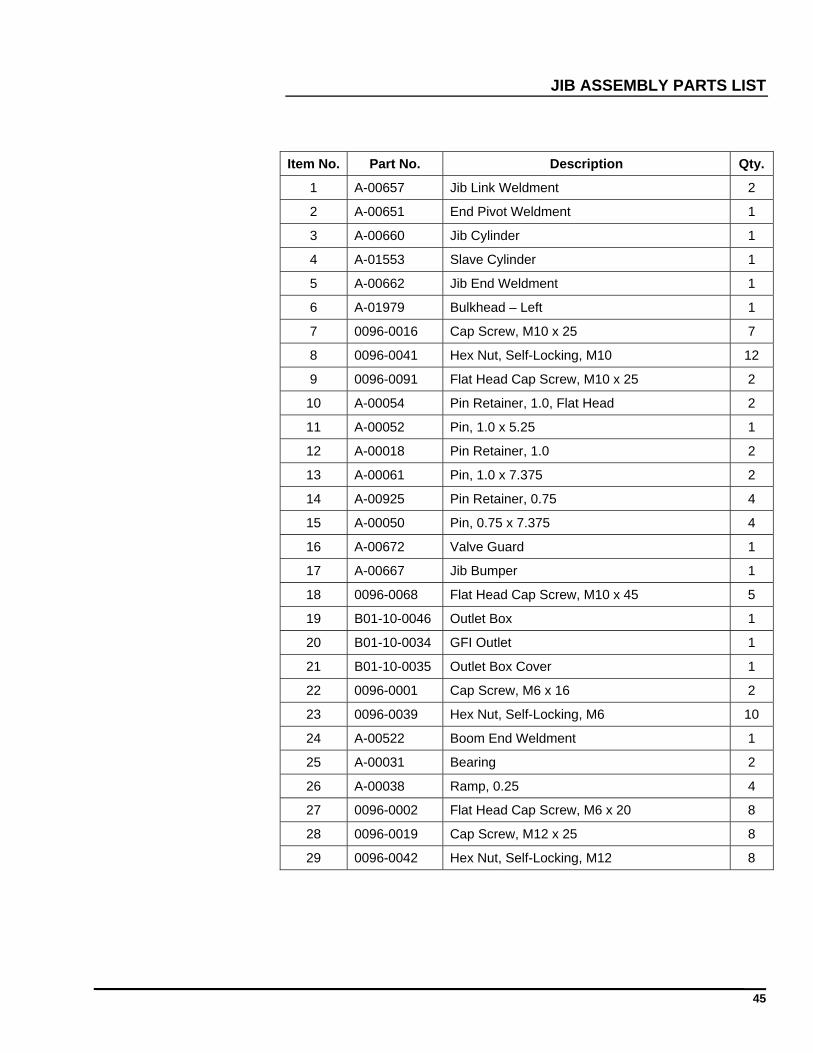
JIB ASSEMBLY PARTS LIST
Item No. Part No. Description Qty.
1 A-00657 Jib Link Weldment 2
2 A-00651 End Pivot Weldment 1
3 A-00660 Jib Cylinder 1
4 A-01553 Slave Cylinder 1
5 A-00662 Jib End Weldment 1
6 A-01979 Bulkhead – Left 1
7 0096-0016 Cap Screw, M10 x 25 7
8 0096-0041 Hex Nut, Self-Locking, M10 12
9 0096-0091 Flat Head Cap Screw, M10 x 25 2
10 A-00054 Pin Retainer, 1.0, Flat Head 2
11 A-00052 Pin, 1.0 x 5.25 1
12 A-00018 Pin Retainer, 1.0 2
13 A-00061 Pin, 1.0 x 7.375 2
14 A-00925 Pin Retainer, 0.75 4
15 A-00050 Pin, 0.75 x 7.375 4
16 A-00672 Valve Guard 1
17 A-00667 Jib Bumper 1
18 0096-0068 Flat Head Cap Screw, M10 x 45 5
19 B01-10-0046 Outlet Box 1
20 B01-10-0034 GFI Outlet 1
21 B01-10-0035 Outlet Box Cover 1
22 0096-0001 Cap Screw, M6 x 16 2
23 0096-0039 Hex Nut, Self-Locking, M6 10
24 A-00522 Boom End Weldment 1
25 A-00031 Bearing 2
26 A-00038 Ramp, 0.25 4
27 0096-0002 Flat Head Cap Screw, M6 x 20 8
28 0096-0019 Cap Screw, M12 x 25 8
29 0096-0042 Hex Nut, Self-Locking, M12 8
46
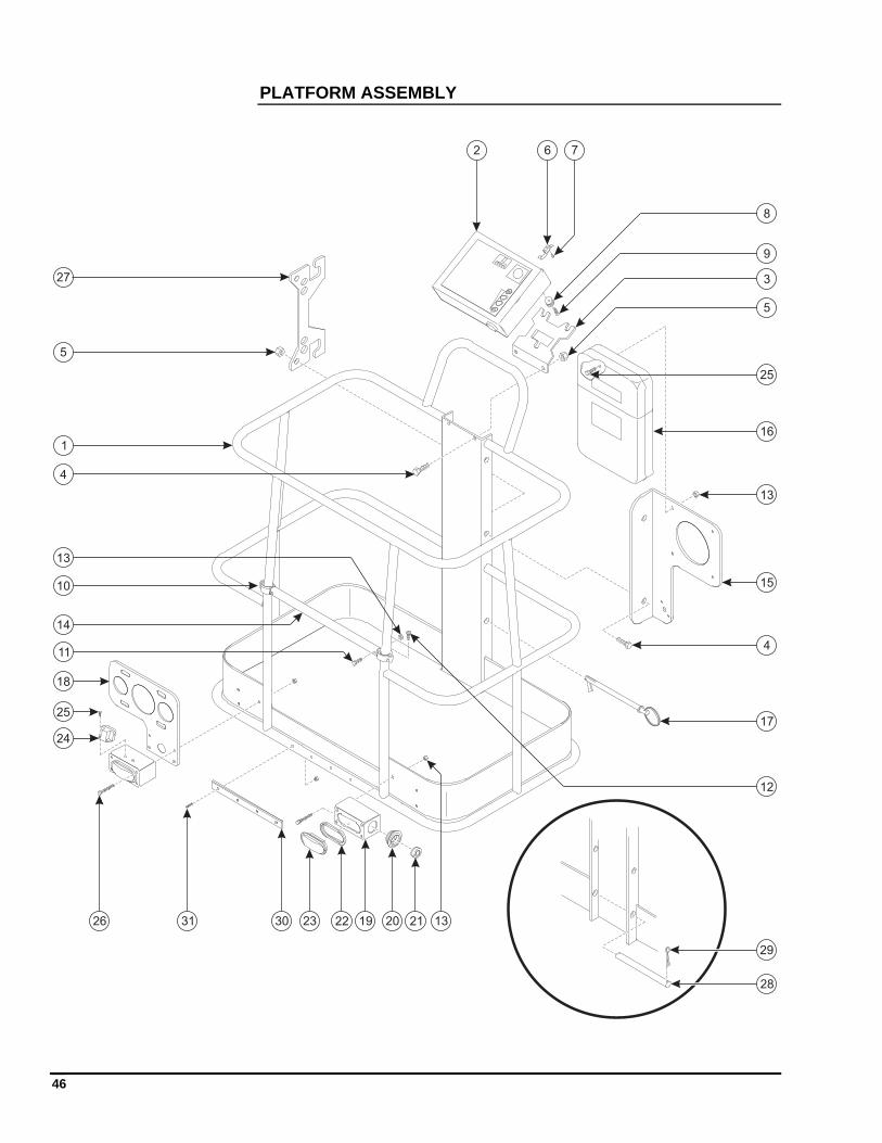
PLATFORM ASSEMBLY
1
2
3
4
5
6 7
8
9
10
11
12
13
4
5
14
15
16
17
19 20 212223
24
25
25
13
1326
18
28
29
27
3031
47
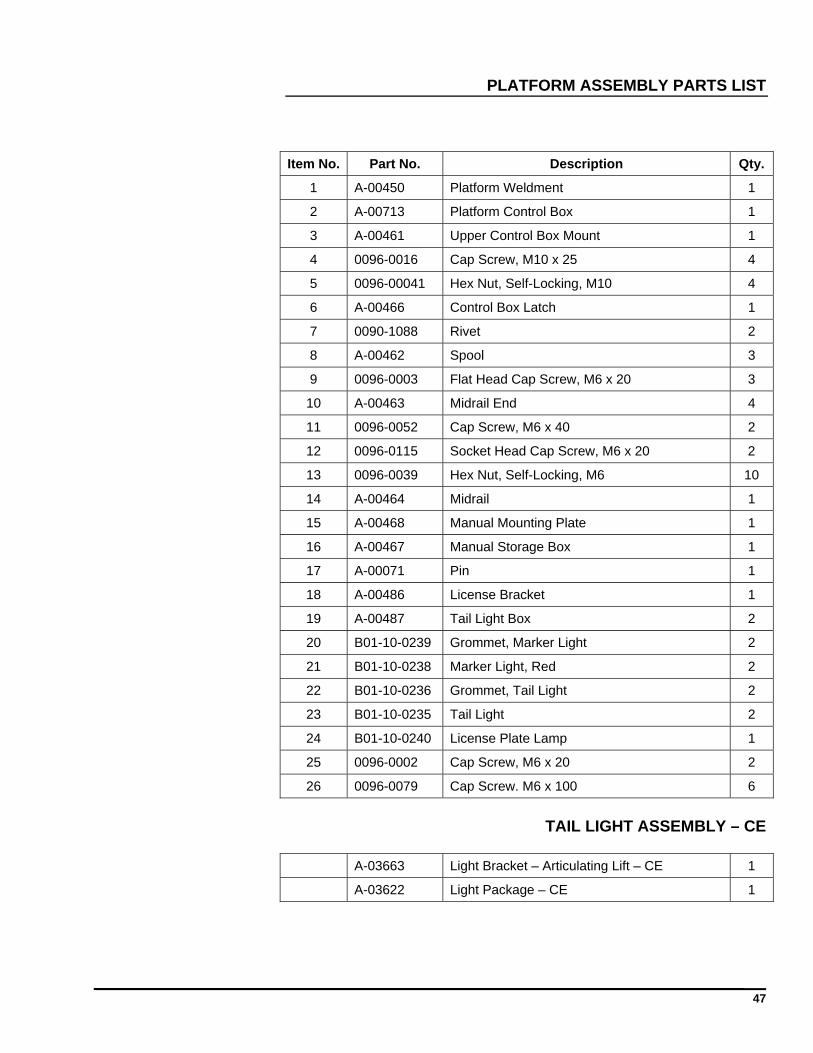
PLATFORM ASSEMBLY PARTS LIST
Item No. Part No. Description Qty.
1 A-00450 Platform Weldment 1
2 A-00713 Platform Control Box 1
3 A-00461 Upper Control Box Mount 1
4 0096-0016 Cap Screw, M10 x 25 4
5 0096-00041 Hex Nut, Self-Locking, M10 4
6 A-00466 Control Box Latch 1
7 0090-1088 Rivet 2
8 A-00462 Spool 3
9 0096-0003 Flat Head Cap Screw, M6 x 20 3
10 A-00463 Midrail End 4
11 0096-0052 Cap Screw, M6 x 40 2
12 0096-0115 Socket Head Cap Screw, M6 x 20 2
13 0096-0039 Hex Nut, Self-Locking, M6 10
14 A-00464 Midrail 1
15 A-00468 Manual Mounting Plate 1
16 A-00467 Manual Storage Box 1
17 A-00071 Pin 1
18 A-00486 License Bracket 1
19 A-00487 Tail Light Box 2
20 B01-10-0239 Grommet, Marker Light 2
21 B01-10-0238 Marker Light, Red 2
22 B01-10-0236 Grommet, Tail Light 2
23 B01-10-0235 Tail Light 2
24 B01-10-0240 License Plate Lamp 1
25 0096-0002 Cap Screw, M6 x 20 2
26 0096-0079 Cap Screw. M6 x 100 6
TAIL LIGHT ASSEMBLY – CE
A-03663 Light Bracket – Articulating Lift – CE 1
A-03622 Light Package – CE 1
48
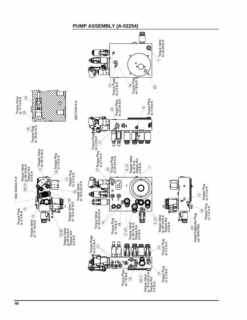
PUMP ASSEMBLY (A-02254)
49
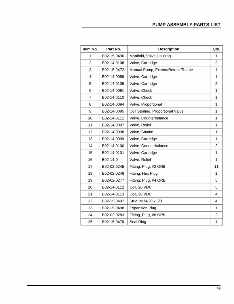
PUMP ASSEMBLY PARTS LIST
Item No. Part No. Description Qty.
1 B02-15-0496 Manifold, Valve Housing 1
2 B02-14-0108 Valve, Cartridge 2
3 B02-15-0472 Manual Pump, Extend/Retract/Rotate 1
4 B02-14-0089 Valve, Cartridge 1
5 B02-14-0109 Valve, Cartridge 2
6 B02-14-0091 Valve, Check 1
7 B02-14-0110 Valve, Check 1
8 B02-14-0094 Valve, Proportional 1
9 B02-14-0095 Coil Sterling, Proportional Valve 1
10 B02-14-0111 Valve, Counterbalance 1
11 B02-14-0097 Valve, Relief 1
12 B02-14-0098 Valve, Shuttle 1
13 B02-14-0099 Valve, Cartridge 1
14 B02-14-0100 Valve, Counterbalance 2
15 B02-14-0101 Valve, Cartridge 1
16 B02-14-0 Valve, Relief 1
17 B02-02-0245 Fitting, Plug, #2 ORB 11
18 B02-02-0246 Fitting, Hex Plug 1
19 B02-02-0277 Fitting, Plug, #4 ORB 5
20 B02-14-0112 Coil, 20 VDC 5
21 B02-14-0113 Coil, 20 VDC 4
22 B02-15-0497 Stud, #1/4-20 x 5/8 4
23 B02-15-0498 Expansion Plug 1
24 B02-02-0283 Fitting, Plug, #6 ORB 2
25 B02-15-0478 Seal Ring 1
50
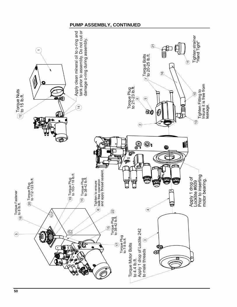
PUMP ASSEMBLY, CONTINUED
51
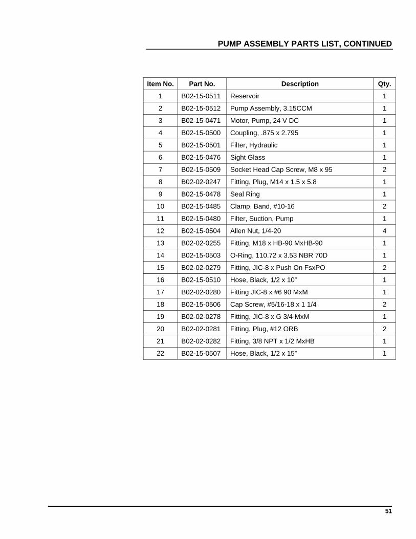
PUMP ASSEMBLY PARTS LIST, CONTINUED
Item No. Part No. Description Qty.
1 B02-15-0511 Reservoir 1
2 B02-15-0512 Pump Assembly, 3.15CCM 1
3 B02-15-0471 Motor, Pump, 24 V DC 1
4 B02-15-0500 Coupling, .875 x 2.795 1
5 B02-15-0501 Filter, Hydraulic 1
6 B02-15-0476 Sight Glass 1
7 B02-15-0509 Socket Head Cap Screw, M8 x 95 2
8 B02-02-0247 Fitting, Plug, M14 x 1.5 x 5.8 1
9 B02-15-0478 Seal Ring 1
10 B02-15-0485 Clamp, Band, #10-16 2
11 B02-15-0480 Filter, Suction, Pump 1
12 B02-15-0504 Allen Nut, 1/4-20 4
13 B02-02-0255 Fitting, M18 x HB-90 MxHB-90 1
14 B02-15-0503 O-Ring, 110.72 x 3.53 NBR 70D 1
15 B02-02-0279 Fitting, JIC-8 x Push On FsxPO 2
16 B02-15-0510 Hose, Black, 1/2 x 10” 1
17 B02-02-0280 Fitting JIC-8 x #6 90 MxM 1
18 B02-15-0506 Cap Screw, #5/16-18 x 1 1/4 2
19 B02-02-0278 Fitting, JIC-8 x G 3/4 MxM 1
20 B02-02-0281 Fitting, Plug, #12 ORB 2
21 B02-02-0282 Fitting, 3/8 NPT x 1/2 MxHB 1
22 B02-15-0507 Hose, Black, 1/2 x 15” 1
52
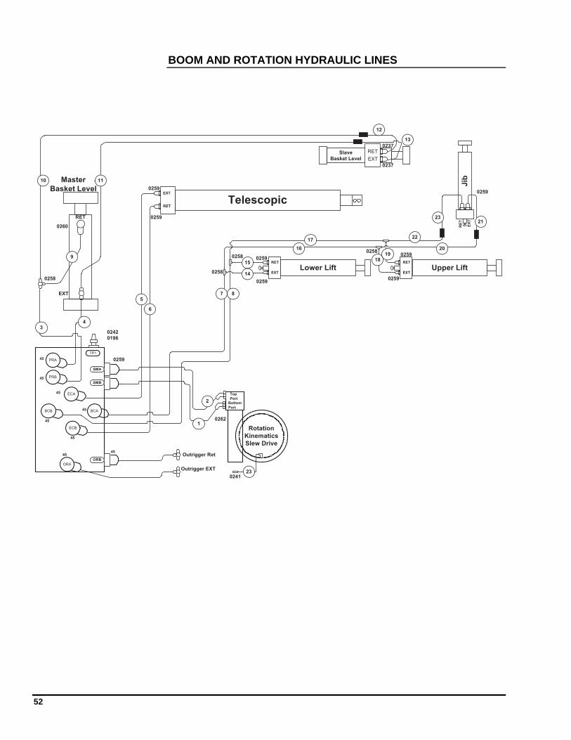
BOOM AND ROTATION HYDRAULIC LINES
ECB
ECA
BCA
PRA
PRB
BCB
Rotation
Kinematics
Slew Drive
TelescopicEXT
RET
EXT
RET
Lower Lift
RET
EXT
RET
EXT
9
10 11
Slave
Basket Level
Master
Basket Level
0259
0259
0259
0259
0237
0237
12
13
Bottom
Port
Top
Port
0262
TP1
EXT
RET
Upper Lift
0259
0259
Jib
0259
Outrigger Ret
Outrigger EXT
14
16
17
1819
20
21
EX
T
RE
T
02580258
0258
ORA
ORB
SMA
SMB
5
6
7 8
34
1
2
0258
0260
0259
0242
0196
4545
45
45
45
45
45
45
15
230241
23
22
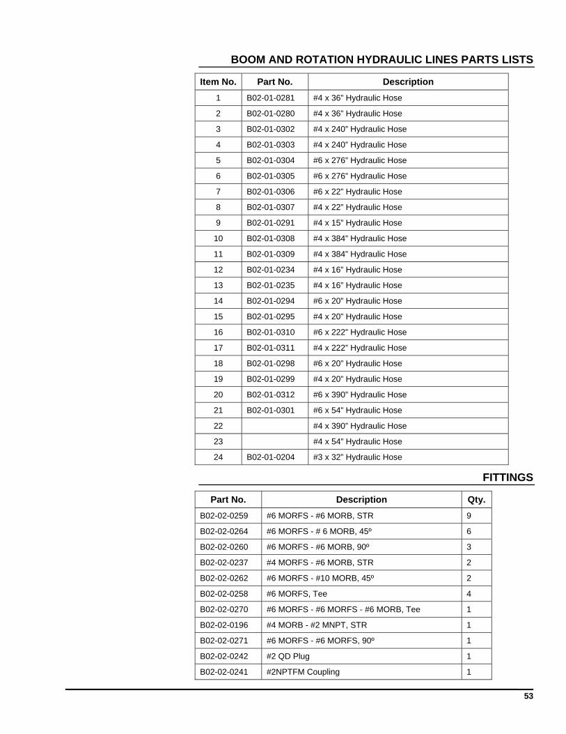
53
BOOM AND ROTATION HYDRAULIC LINES PARTS LISTS
Item No. Part No. Description
1 B02-01-0281 #4 x 36” Hydraulic Hose
2 B02-01-0280 #4 x 36” Hydraulic Hose
3 B02-01-0302 #4 x 240” Hydraulic Hose
4 B02-01-0303 #4 x 240” Hydraulic Hose
5 B02-01-0304 #6 x 276” Hydraulic Hose
6 B02-01-0305 #6 x 276” Hydraulic Hose
7 B02-01-0306 #6 x 22” Hydraulic Hose
8 B02-01-0307 #4 x 22” Hydraulic Hose
9 B02-01-0291 #4 x 15” Hydraulic Hose
10 B02-01-0308 #4 x 384” Hydraulic Hose
11 B02-01-0309 #4 x 384” Hydraulic Hose
12 B02-01-0234 #4 x 16” Hydraulic Hose
13 B02-01-0235 #4 x 16” Hydraulic Hose
14 B02-01-0294 #6 x 20” Hydraulic Hose
15 B02-01-0295 #4 x 20” Hydraulic Hose
16 B02-01-0310 #6 x 222” Hydraulic Hose
17 B02-01-0311 #4 x 222” Hydraulic Hose
18 B02-01-0298 #6 x 20” Hydraulic Hose
19 B02-01-0299 #4 x 20” Hydraulic Hose
20 B02-01-0312 #6 x 390” Hydraulic Hose
21 B02-01-0301 #6 x 54” Hydraulic Hose
22 #4 x 390” Hydraulic Hose
23 #4 x 54” Hydraulic Hose
24 B02-01-0204 #3 x 32” Hydraulic Hose
FITTINGS
Part No. Description Qty.
B02-02-0259 #6 MORFS - #6 MORB, STR 9
B02-02-0264 #6 MORFS - # 6 MORB, 45º 6
B02-02-0260 #6 MORFS - #6 MORB, 90º 3
B02-02-0237 #4 MORFS - #6 MORB, STR 2
B02-02-0262 #6 MORFS - #10 MORB, 45º 2
B02-02-0258 #6 MORFS, Tee 4
B02-02-0270 #6 MORFS - #6 MORFS - #6 MORB, Tee 1
B02-02-0196 #4 MORB - #2 MNPT, STR 1
B02-02-0271 #6 MORFS - #6 MORFS, 90º 1
B02-02-0242 #2 QD Plug 1
B02-02-0241 #2NPTFM Coupling 1
54
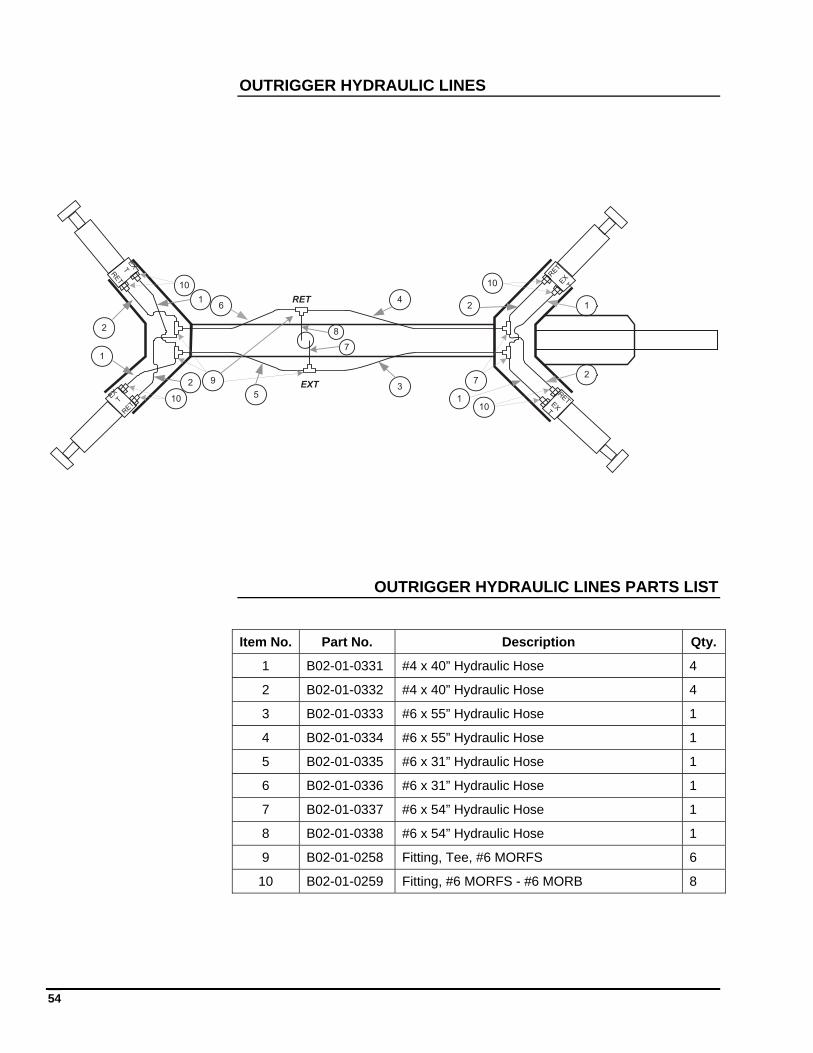
OUTRIGGER HYDRAULIC LINES
EXT
RET
RET
EX
TRET
EXT
EX
T
RET
EXT
RET
2
14
6
1
9 7
10
10 10
101
35
2
2
12
7
8
OUTRIGGER HYDRAULIC LINES PARTS LIST
Item No. Part No. Description Qty.
1 B02-01-0331 #4 x 40” Hydraulic Hose 4
2 B02-01-0332 #4 x 40” Hydraulic Hose 4
3 B02-01-0333 #6 x 55” Hydraulic Hose 1
4 B02-01-0334 #6 x 55” Hydraulic Hose 1
5 B02-01-0335 #6 x 31” Hydraulic Hose 1
6 B02-01-0336 #6 x 31” Hydraulic Hose 1
7 B02-01-0337 #6 x 54” Hydraulic Hose 1
8 B02-01-0338 #6 x 54” Hydraulic Hose 1
9 B02-01-0258 Fitting, Tee, #6 MORFS 6
10 B02-01-0259 Fitting, #6 MORFS - #6 MORB 8
55
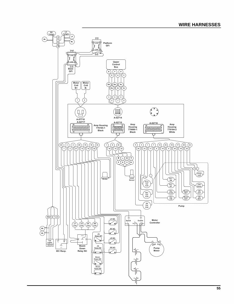
WIRE HARNESSES
Amp
Housing
770680-1
Black
Amp Housing
776164-1
Black
A-02717Amp
Housing
776164-2
White
A-02716
112
2436
112
2435
A-02715
18
23 16
LF
Coil
LR
Coil
RF
Coil
RR
Coil
LF NO
LR NO
RF NO
RR NO
24
1
3
2
4
27
26
13
15
14
16
22
23
Strobe
1
16
3 1
B- B+M-
Pump
Motor
A2E2 D1E1
EnableSpeed
R B O Br
+ - X Y
8
15
22
23
1
11
7
8
13
14
+-
23
9
10
34
17
18
35
32
33
PLT
DN
PLT
UP
Rot
CCW
Rot
CW
Boom
RET
Boom
EXT
Prop
Coil
Chk
Valve
OR
EXT
OR
RET
+ -
Motor
Controller
A-01718
1 2
Motor
Cntl
B+
Motor
Cntl
B-
3
4
6
7
8
9
Wh
Blu
Bla
Or
Re
Gr
B
E
F
A
D
C
Upper
Control
Box
Line
Load
Wh
iteH
ot
Line
Load
Wh
iteH
ot
L N
W B Y G
Tail
Lights
G
Y
B
W
RH
Tailight
LH
Tailight
ML
ML
LP
Level
Sensor
Jib
Down NO
Jib
Down NC
IEC Recp.
Boom
Down
Relay NC
A-02714
ML
ML
Platform
GFI
Base
GFI
Pump
Boom
Down NC
Boom
Down NO
12
3
22
5
Prim
Cyl
Coil
Sec
Cyl
Coil
Jib
Cyl
Coil
56
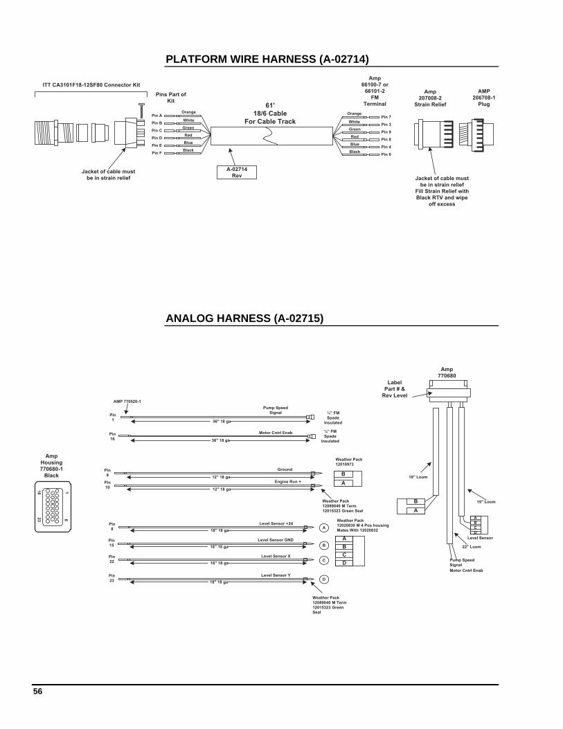
PLATFORM WIRE HARNESS (A-02714)
Orange
WhitePin A
Pin B
Pin CGreen
Pin DRed
Pin EBlue
Pin FBlack
Orange
White
Pin 7
Pin 3
Pin 9Green
Pin 8Red
Pin 4Blue
Pin 6Black
61'
18/6 Cable
For Cable Track
ITT CA3101F18-12SF80 Connector Kit
Jacket of cable must
be in strain relief Jacket of cable must
be in strain relief
Fill Strain Relief with
Black RTV and wipe
off excess
Pins Part of
Kit
A-02714
Rev
Amp
66100-7 or
66101-2
FM
Terminal
AMP
206708-1
Plug
Amp
207008-2
Strain Relief
ANALOG HARNESS (A-02715)
Amp
Housing
770680-1
Black
Pin
1
¼” FM
Spade
Insulated
Pump Speed
Signal
36" 18 ga
Pin
16
Motor Cntrl Enab
36" 18 ga
¼” FM
Spade
Insulated
Pin
8 18" 18 ga
Level Sensor +24
Pin
15 18" 18 ga
Level Sensor GND
Pin
22 18" 18 ga
Level Sensor X
Pin
23 18" 18 ga
Level Sensor Y
A
B
C
D
A
B
C
D
Weather Pack
12020830 M 4 Pos housing
Mates With 12020832
Weather Pack
12089040 M Term
12015323 Green
Seal
Amp
770680
A
B
C
D
Level Sensor
Pump Speed
Signal
Motor Cntrl Enab
15" Loom
22" Loom
AMP 770520-1
Label
Part # &
Rev Level
Pin
1012" 18 ga
Pin
912" 18 ga
Engine Run +
Ground
B
A
Weather Pack
12010973
Weather Pack
12089040 M Term
12015323 Green Seal
1823
16
B
A
10" Loom
57
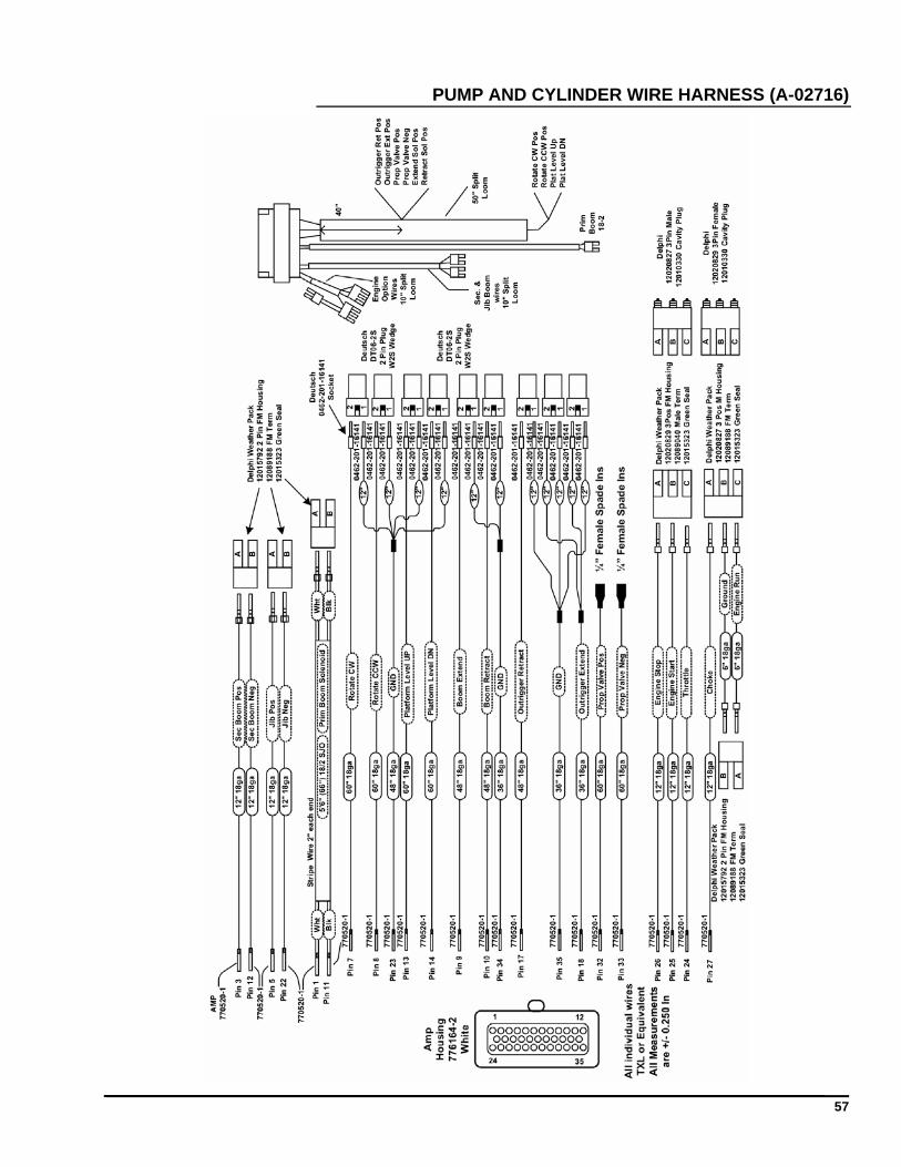
PUMP AND CYLINDER WIRE HARNESS (A-02716)
58
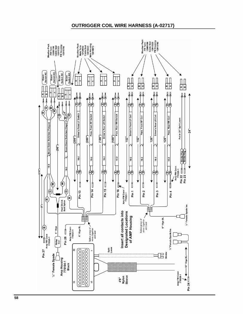
OUTRIGGER COIL WIRE HARNESS (A-02717)
59
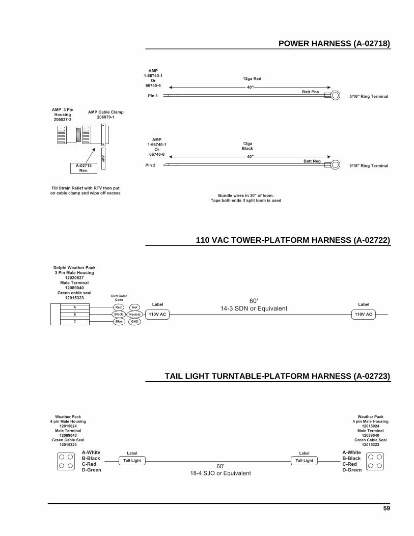
POWER HARNESS (A-02718)
AM
P
5/16" Ring Terminal
AMP
1-66740-1
Or
66740-6
5/16" Ring Terminal
AMP
1-66740-1
Or
66740-6
12ga Red
40"
40"
12ga
Black
Pin 2
Pin 1
Fill Strain Relief with RTV then put
on cable clamp and wipe off excessBundle wires in 30" of loom.
Tape both ends if split loom is used
Batt Pos
Batt Neg
AMP 3 Pin
Housing
206037-2
AMP Cable Clamp
206070-1
A-02718
Rev.
110 VAC TOWER-PLATFORM HARNESS (A-02722)
Delphi Weather Pack
3 Pin Male Housing
12020827
Male Terminal
12089040
Green cable seal
1201532360'
14-3 SDN or EquivalentLabel
Red
Black
Blue
Hot
Neutral
GND
110V AC
Label
110V AC
SDN Color
Code
A
B
C
TAIL LIGHT TURNTABLE-PLATFORM HARNESS (A-02723)
A-White
B-Black
C-Red
D-Green
A-White
B-Black
C-Red
D-Green
Weather Pack
4 pin Male Housing
12015024
Male Terminal
12089040
Green Cable Seal
12015323
Weather Pack
4 pin Male Housing
12015024
Male Terminal
12089040
Green Cable Seal
12015323
60'
18-4 SJO or Equivalent
Tail LightTail Light
Label Label
60
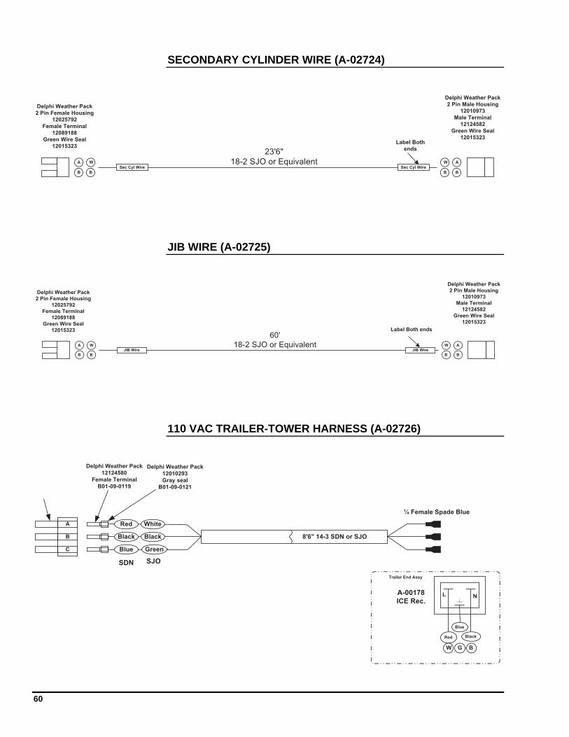
SECONDARY CYLINDER WIRE (A-02724)
A
B
A
BB
W
B
W
23'6"
18-2 SJO or EquivalentSec Cyl Wire Sec Cyl Wire
Label Both
ends
Delphi Weather Pack
2 Pin Female Housing
12025792
Female Terminal
12089188
Green Wire Seal
12015323
Delphi Weather Pack
2 Pin Male Housing
12010973
Male Terminal
12124582
Green Wire Seal
12015323
JIB WIRE (A-02725)
A
B
A
BB
W
B
W
60'
18-2 SJO or EquivalentJIB Wire JIB Wire
Label Both ends
Delphi Weather Pack
2 Pin Female Housing
12025792
Female Terminal
12089188
Green Wire Seal
12015323
Delphi Weather Pack
2 Pin Male Housing
12010973
Male Terminal
12124582
Green Wire Seal
12015323
110 VAC TRAILER-TOWER HARNESS (A-02726)
Black
White
Green
8'6" 14-3 SDN or SJO
Delphi Weather Pack
12010293
Gray seal
B01-09-0121
¼ Female Spade Blue
C
B
A
Delphi Weather Pack
12124580
Female Terminal
B01-09-0119
Red Black
Blue
A-00178
ICE Rec.L N
Trailer End Assy
Red
Black
Blue
SDN SJO
W G B
61
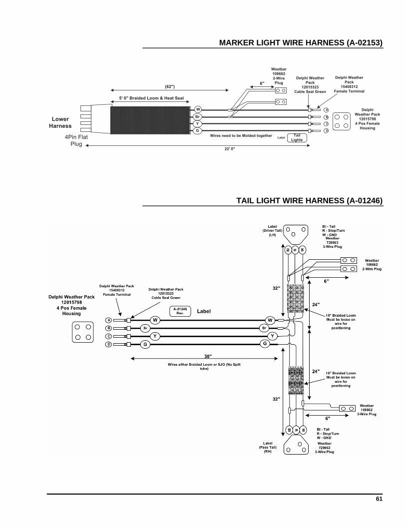
MARKER LIGHT WIRE HARNESS (A-02153)
Br
W
Y
G
A
B
C
D
Delphi
Weather Pack
12015798
4 Pos Female
Housing
Delphi Weather
Pack
15408312
Female Terminal
Delphi Weather
Pack
12015323
Cable Seal Green
Westbar
108662
2-Wire
Plug
5' 0" Braided Loom & Heat Seal
(62")
22' 0"
6"
4Pin Flat
Plug
Lower
Harness
Tail
LightsLabel
Wires need to be Molded together
TAIL LIGHT WIRE HARNESS (A-01246)
62
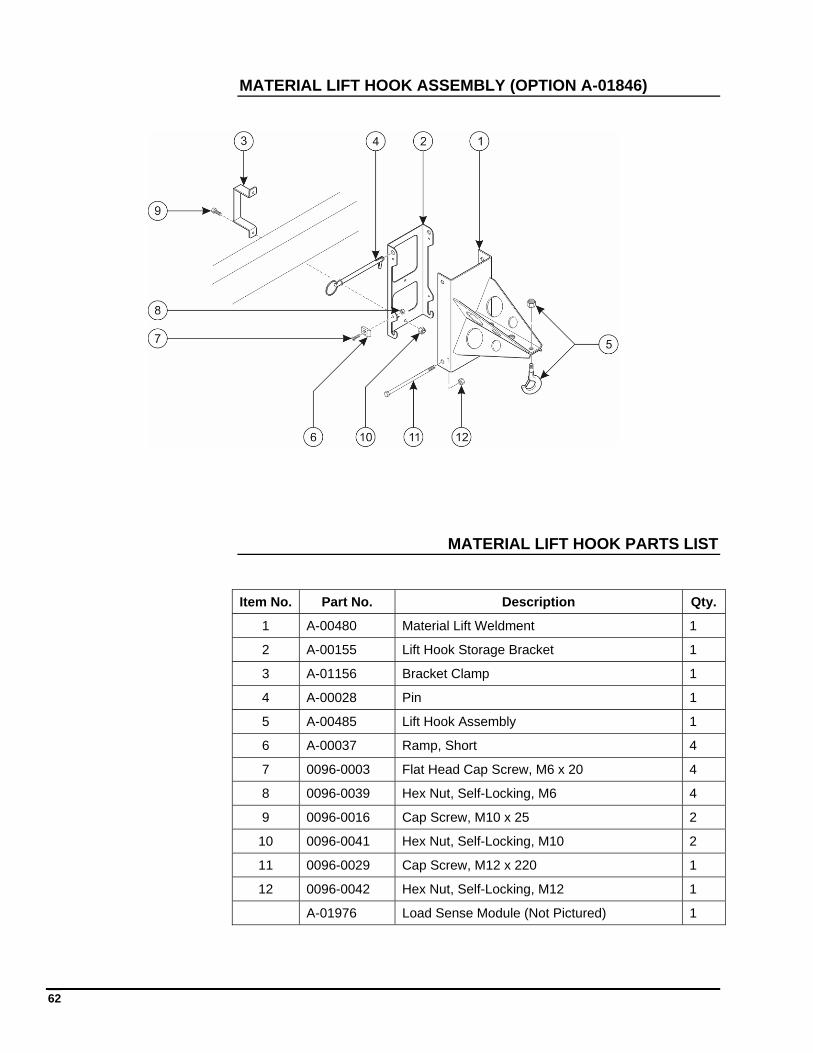
MATERIAL LIFT HOOK ASSEMBLY (OPTION A-01846)
MATERIAL LIFT HOOK PARTS LIST
Item No. Part No. Description Qty.
1 A-00480 Material Lift Weldment 1
2 A-00155 Lift Hook Storage Bracket 1
3 A-01156 Bracket Clamp 1
4 A-00028 Pin 1
5 A-00485 Lift Hook Assembly 1
6 A-00037 Ramp, Short 4
7 0096-0003 Flat Head Cap Screw, M6 x 20 4
8 0096-0039 Hex Nut, Self-Locking, M6 4
9 0096-0016 Cap Screw, M10 x 25 2
10 0096-0041 Hex Nut, Self-Locking, M10 2
11 0096-0029 Cap Screw, M12 x 220 1
12 0096-0042 Hex Nut, Self-Locking, M12 1
A-01976 Load Sense Module (Not Pictured) 1
63
WATER LINE TO PLATFORM (OPTION A-02701)
Part No. Description
B09-00-0042 #6 x 146” W/1-6-6FMP, 1-6-6MP 3000 PSI Pressure Washer Hose
B09-00-0043 #6 x 628” W/2-6-6MPSW 3000 PSI Pressure Washer Hose
B09-00-0041 #6 x 78” W/1-6-6FMP, 1-6-6MP 3000 PSI Pressure Washer Hose
B09-00-0032 Fitting, QD E Series FM-#6FMNPT
B09-00-0033 Fitting, QD E Series M-#6FMNPT
AIR LINE TO PLATFORM (OPTION A-02700)
Part No. Description
B09-00-0037 #6 x 146” W/1-6-6FMPSW, 1-6-6MP 300 PSI Air Hose
B09-00-0038 #6 x 628” W/2-6-6MP 300 PSI Air Hose
B09-00-0036 #6 x 78” W/1-6-6FMPSW, 1-6-6MP 300 PSI Air Hose
B02-02-0108 Fitting, #6FMNPT-#4FMNPT STR
B09-00-0025 Fitting, Univ QD FM-#4MNPT
B09-00-0026 Fitting, QD IND Series M-#4MNPT
B09-00-0027 Fitting,QD ARO Series M-#4MNPT
B09-00-0028 Fitting, Univ QD FM-#6FMNPT
B09-00-0029 Fitting, QD DF Series M-#6FMNPT
B09-00-0030 Fitting, QD J Series M-#6FMNPT
64
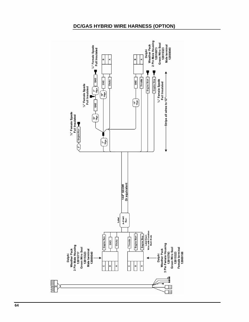
DC/GAS HYBRID WIRE HARNESS (OPTION)
65
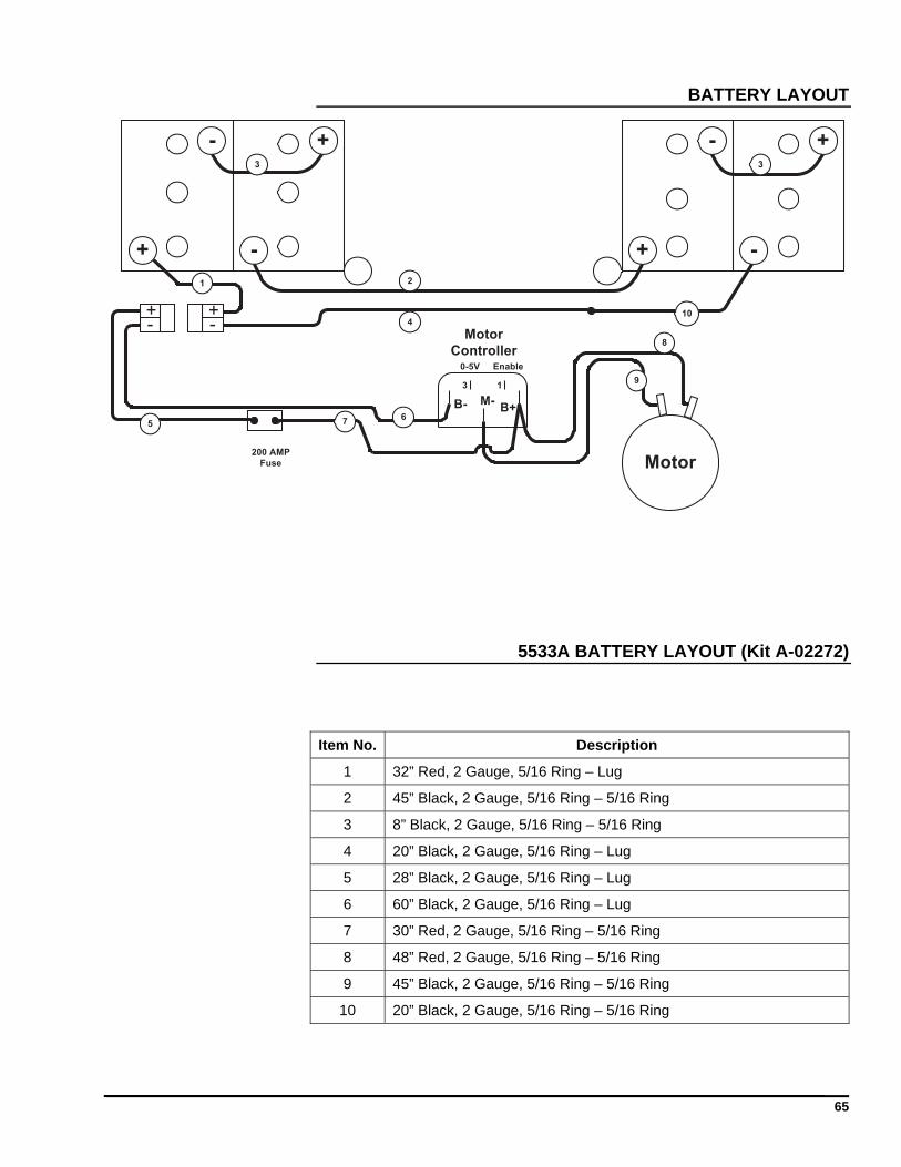
BATTERY LAYOUT
+
- +
- +
- +
-
-+
-+
Motor
2
3 3
4
8
9
10
200 AMP
Fuse
B+B- M-
Motor
ControllerEnable0-5V
13
7
1
56
5533A BATTERY LAYOUT (Kit A-02272)
Item No. Description
1 32” Red, 2 Gauge, 5/16 Ring – Lug
2 45” Black, 2 Gauge, 5/16 Ring – 5/16 Ring
3 8” Black, 2 Gauge, 5/16 Ring – 5/16 Ring
4 20” Black, 2 Gauge, 5/16 Ring – Lug
5 28” Black, 2 Gauge, 5/16 Ring – Lug
6 60” Black, 2 Gauge, 5/16 Ring – Lug
7 30” Red, 2 Gauge, 5/16 Ring – 5/16 Ring
8 48” Red, 2 Gauge, 5/16 Ring – 5/16 Ring
9 45” Black, 2 Gauge, 5/16 Ring – 5/16 Ring
10 20” Black, 2 Gauge, 5/16 Ring – 5/16 Ring
66
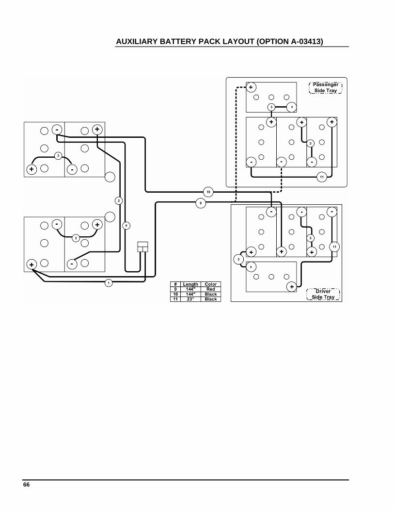
AUXILIARY BATTERY PACK LAYOUT (OPTION A-03413)
67
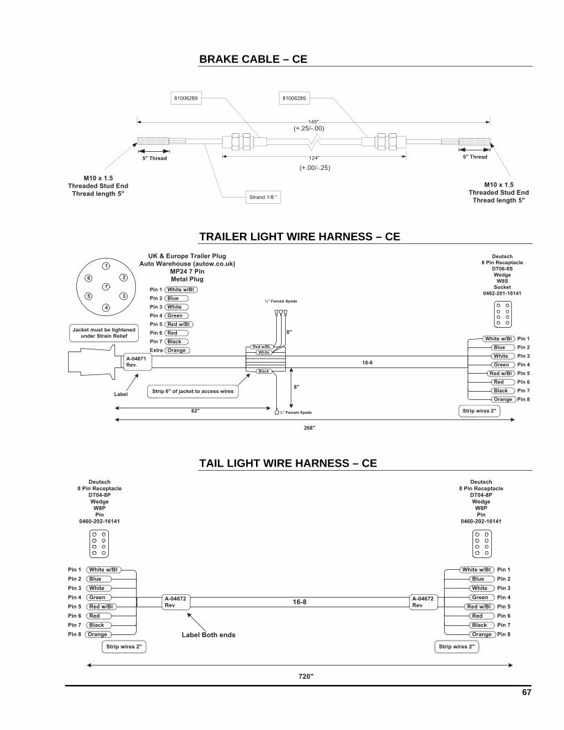
BRAKE CABLE – CE
124"
145"
81006289 81006289
Strand 1/8 “
(+.00/-.25)
(+.25/-.00)
M10 x 1.5
Threaded Stud End
Thread length 5"
M10 x 1.5
Threaded Stud End
Thread length 5"
5" Thread5" Thread
TRAILER LIGHT WIRE HARNESS – CE
7
4
1
26
35
UK & Europe Trailer Plug
Auto Warehouse (autow.co.uk)
MP24 7 Pin
Metal Plug
Pin 1
Pin 2
Pin 3
White w/Bl
Blue
White
Green
Red w/Bl
Pin 4
Pin 5
Pin 6
Pin 7
Red
Black
White
Red w/BL
Black
Pin 1
Pin 2
Pin 3
White w/Bl
Blue
White
Green
Red w/Bl
Pin 4
Pin 5
Pin 6
Pin 7
Red
Black
Deutsch
8 Pin Receptacle
DT06-8S
Wedge
W8S
Socket
0462-201-16141
Orange Pin 8
268"
62"
8"
8"
¼” Female Spade
¼” Female Spade
Extra Orange
Strip 6" of jacket to access wires
Jacket must be tightened
under Strain Relief
Strip wires 2"
A-04671
Rev.
Label
18-8
TAIL LIGHT WIRE HARNESS – CE
Pin 1
Pin 2
Pin 3
White w/Bl
Blue
White
Green
Red w/Bl
Pin 4
Pin 5
Pin 6
Pin 7
Red
Black
Deutsch
8 Pin Receptacle
DT04-8P
Wedge
W8P
Pin
0460-202-16141
OrangePin 8
Strip wires 2"
Pin 1
Pin 2
Pin 3
White w/Bl
Blue
White
Green
Red w/Bl
Pin 4
Pin 5
Pin 6
Pin 7
Red
Black
Deutsch
8 Pin Receptacle
DT04-8P
Wedge
W8P
Pin
0460-202-16141
Orange Pin 8
Strip wires 2"
720"
16-8A-04672
Rev
A-04672
Rev
Label Both ends

68
69
ORDERING REPLACEMENT PARTS
To order replacement parts, contact the Haulotte Group | BilJax Service Department by phone at 800-537-0540, by fax at 419-446-8202 or by email at [email protected].
For swift service, always have the part number available, as well as the equipment model and serial number. When ordering parts by fax or email, always provide the above information.
QUICK REFERENCE
Equipment Model: Haulotte Group | BilJax 5533A Articulating Boom Lift
Serial Number: ______________________________________________
NOTES

71
HAULOTTE GROUP | BILJAX MODEL 5533A QUICK START GUIDE
Obtain, read and obey all Safety Guidelines:
In this manual
Attached to the boom lift
Indicated by federal, state and local regulations
Position the boom lift in work area
Unhitch from the tow vehicle and disengage all boom travel latches
Turn Key Switch to ground control station for outrigger extension and leveling
Extend outriggers and level the boom
Press and hold the outrigger EXTEND and AUTO LEVEL buttons
A buzzer will sound and all LEDs will become lit on the Outrigger Control Panel when the boom is level
Turn Key Switch to platform control station.
Enter the work platform and attach safety harness to the Fall Protection Attachment Point
Press and hold the desired SPEED and function buttons to operate boom lift
NOTES

72
125 Taylor Parkway Archbold, OH 43502 Phone (419) 445-8915 (800) 537-0540 Fax (419) 445-0367
Distributed by:


![b33 Mics(Ndpl)[1]](https://img.pdfslide.us/doc/110x75/577ce6541a28abf103929b35/b33-micsndpl1.jpg)