Embed Size (px)
Citation preview
I M P R SI M P R S K.K.--LindauLindau, 29 , 29 OctOct 20102010
R. R. MellerMeller / H./ H. HartwigHartwig #1#1
IMPRS IMPRS LecturesLectures ononSPACE INSTRUMENTATIONSPACE INSTRUMENTATION
2525--29 29 OctoberOctober 20102010MPS , KatlenburgMPS , Katlenburg--Lindau :Lindau :
SpaceSpace Instrument Instrument DevelopmentDevelopment((basedbased on on lecturelecture byby Hermann Hartwig, Hermann Hartwig, DecDec. 2006) . 2006)
Reinhard Reinhard MellerMeller, MPS, MPS
I M P R SI M P R S SpaceSpace InstrumentInstrument DevelopmentDevelopment K.K.--LindauLindau, 29 , 29 OctOct 20102010
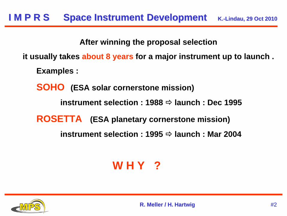
After winning the proposal selection
it usually takes about 8 years for a major instrument up to launch .
Examples :
SOHO (ESA solar cornerstone mission)
instrument selection : 1988 launch : Dec 1995
ROSETTA (ESA planetary cornerstone mission)
instrument selection : 1995 launch : Mar 2004
W H Y ?
R. R. MellerMeller / H./ H. HartwigHartwig #2#2
Commercial off-the-shelf (COTS) instruments usually will not work
for space because they
are too heavy
will not survive the launch loads
will stop functioning under space conditions:
space is a very hostile environment !
I M P R SI M P R S SpaceSpace InstrumentInstrument DevelopmentDevelopment K.K.--LindauLindau, 29 , 29 OctOct 20102010
R. R. MellerMeller / H./ H. HartwigHartwig #3#3
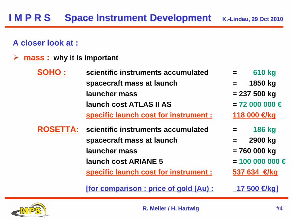
A closer look at :
mass : why it is important
SOHO : scientific instruments accumulated = 610 kgspacecraft mass at launch = 1850 kglauncher mass = 237 500 kglaunch cost ATLAS II AS = 72 000 000 €specific launch cost for instrument : 118 000 €/kg
ROSETTA: scientific instruments accumulated = 186 kgspacecraft mass at launch = 2900 kglauncher mass = 760 000 kglaunch cost ARIANE 5 = 100 000 000 €specific launch cost for instrument : 537 634 €/kg
[for comparison : price of gold (Au) : 17 500 €/kg]
I M P R SI M P R S SpaceSpace InstrumentInstrument DevelopmentDevelopment K.K.--LindauLindau, 29 , 29 OctOct 20102010
R. R. MellerMeller / H./ H. HartwigHartwig #4#4
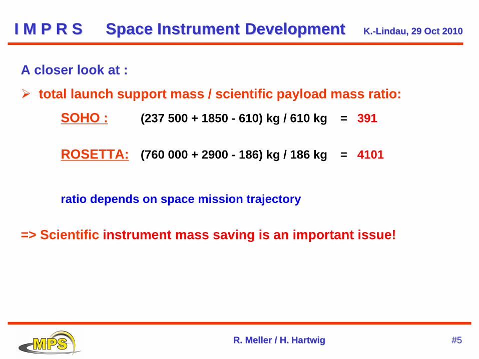
A closer look at :
total launch support mass / scientific payload mass ratio:
SOHO : (237 500 + 1850 - 610) kg / 610 kg = 391
ROSETTA: (760 000 + 2900 - 186) kg / 186 kg = 4101
ratio depends on space mission trajectory
=> Scientific instrument mass saving is an important issue!
I M P R SI M P R S SpaceSpace InstrumentInstrument DevelopmentDevelopment K.K.--LindauLindau, 29 , 29 OctOct 20102010
R. R. MellerMeller / H./ H. HartwigHartwig #5#5
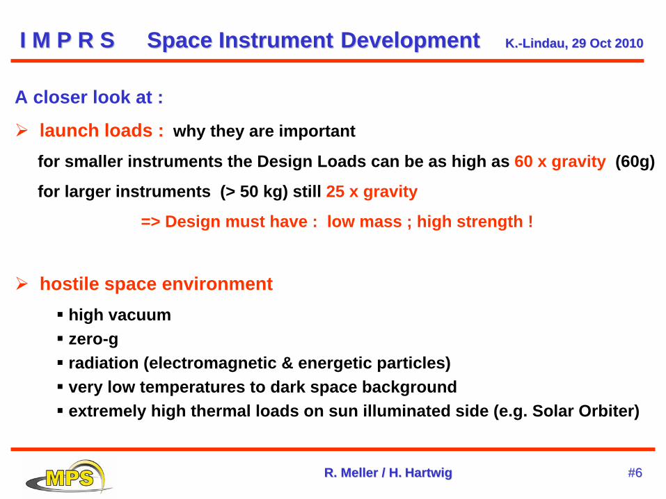
A closer look at :
launch loads : why they are important
for smaller instruments the Design Loads can be as high as 60 x gravity (60g)
for larger instruments (> 50 kg) still 25 x gravity
=> Design must have : low mass ; high strength !
hostile space environment high vacuum zero-g radiation (electromagnetic & energetic particles) very low temperatures to dark space background extremely high thermal loads on sun illuminated side (e.g. Solar Orbiter)
I M P R SI M P R S SpaceSpace InstrumentInstrument DevelopmentDevelopment K.K.--LindauLindau, 29 , 29 OctOct 20102010
R. R. MellerMeller / H./ H. HartwigHartwig #6#6
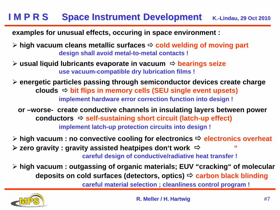
examples for unusual effects, occuring in space environment :
high vacuum cleans metallic surfaces cold welding of moving part design shall avoid metal-to-metal contacts !
usual liquid lubricants evaporate in vacuum bearings seize use vacuum-compatible dry lubrication films !
energetic particles passing through semiconductor devices create charge clouds bit flips in memory cells (SEU single event upsets)
implement hardware error correction function into design !
or –worse- create conductive channels in insulating layers between power conductors self-sustaining short circuit (latch-up effect)
implement latch-up protection circuits into design !
high vacuum : no convective cooling for electronics electronics overheat
zero gravity : gravity assisted heatpipes don‘t work
“ careful design of conductive/radiative heat transfer !
high vacuum : outgassing of organic materials; EUV “cracking“ of molecular deposits on cold surfaces (detectors, optics) carbon black blinding
careful material selection ; cleanliness control program !
I M P R SI M P R S SpaceSpace InstrumentInstrument DevelopmentDevelopment K.K.--LindauLindau, 29 , 29 OctOct 20102010
R. R. MellerMeller / H./ H. HartwigHartwig #7#7
For all these reasons
space instruments are custom-designed one-of-a-kind items
building these unique instruments follows a universal pattern :
●
staged development with milestone peer reviews
●
succession of models with increasing complexity and level of detail
I M P R SI M P R S SpaceSpace InstrumentInstrument DevelopmentDevelopment K.K.--LindauLindau, 29 , 29 OctOct 20102010
R. R. MellerMeller / H./ H. HartwigHartwig #8#8
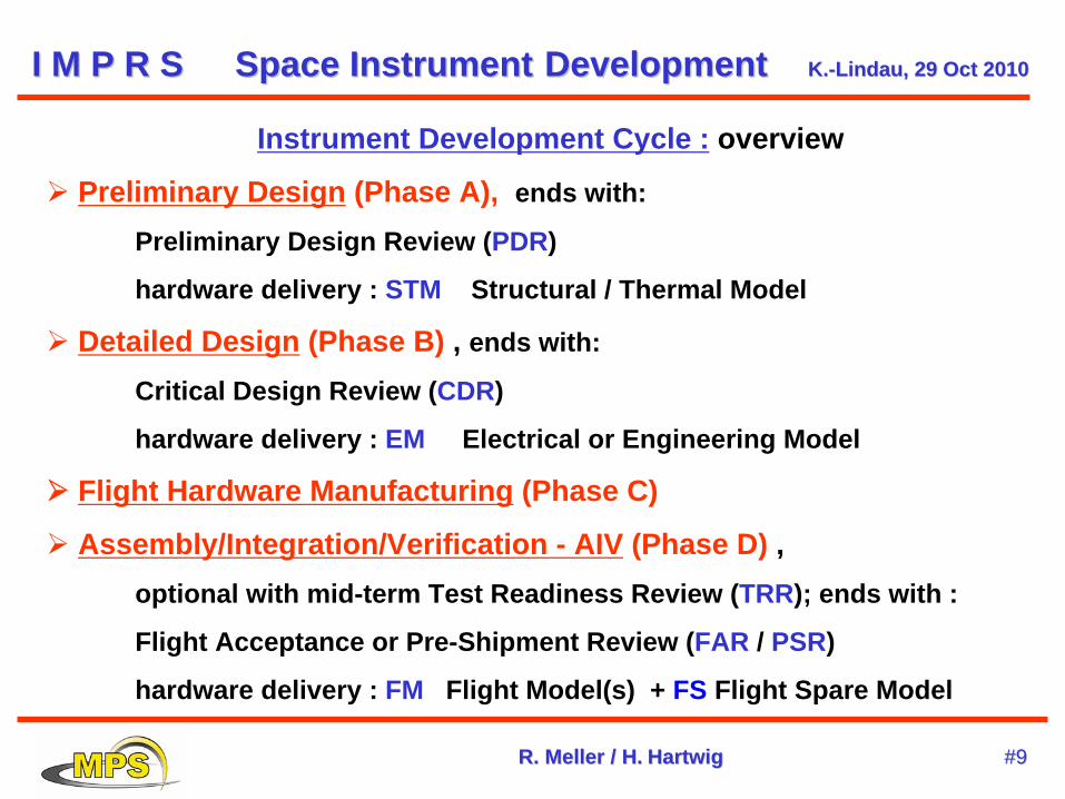
Instrument Development Cycle : overview
Preliminary Design (Phase A), ends with:
Preliminary Design Review (PDR)
hardware delivery : STM Structural / Thermal Model
Detailed Design (Phase B) , ends with:
Critical Design Review (CDR)
hardware delivery : EM Electrical or Engineering Model
Flight Hardware Manufacturing (Phase C)
Assembly/Integration/Verification - AIV (Phase D) , optional with mid-term Test Readiness Review (TRR); ends with :
Flight Acceptance or Pre-Shipment Review (FAR / PSR)
hardware delivery : FM Flight Model(s) + FS Flight Spare Model
I M P R SI M P R S SpaceSpace InstrumentInstrument DevelopmentDevelopment K.K.--LindauLindau, 29 , 29 OctOct 20102010
R. R. MellerMeller / H./ H. HartwigHartwig #9#9
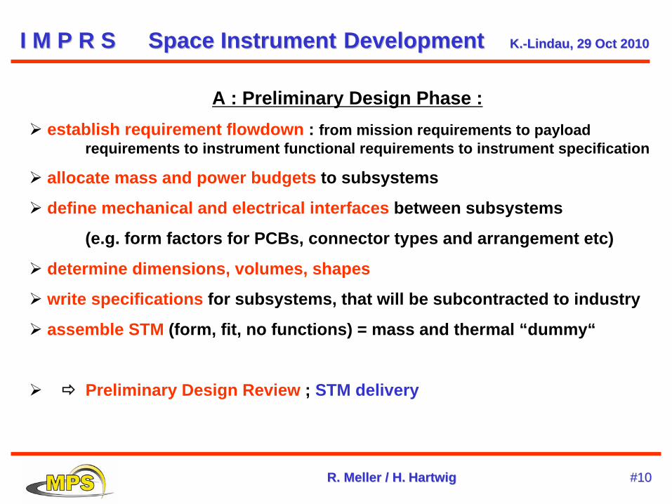
A : Preliminary Design Phase :
establish requirement flowdown : from mission requirements to payload requirements to instrument functional requirements to instrument specification
allocate mass and power budgets to subsystems
define mechanical and electrical interfaces between subsystems
(e.g. form factors for PCBs, connector types and arrangement etc)
determine dimensions, volumes, shapes
write specifications for subsystems, that will be subcontracted to industry
assemble STM (form, fit, no functions) = mass and thermal “dummy“
Preliminary Design Review ; STM delivery
I M P R SI M P R S SpaceSpace InstrumentInstrument DevelopmentDevelopment K.K.--LindauLindau, 29 , 29 OctOct 20102010
R. R. MellerMeller / H./ H. HartwigHartwig #10#10
6
DAWNA Journey to the Beginning of the Solar System
Framing Camera MPAe – DLR – IDA
Science Objectives and Requirements
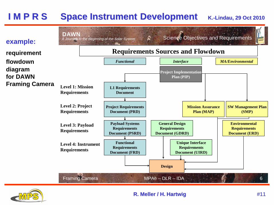
Requirements Sources and Flowdown
Functional Requirements
Document (FRD)
Unique InterfaceRequirements
Document (UIRD)
Environmental Requirements
Document (ERD)
Mission AssurancePlan (MAP)
Level 1: Mission Requirements
Level 2: ProjectRequirements
Level 4: Instrument Requirements
Level 3: Payload Requirements
L1 Requirements Document
Project Requirements Document (PRD)
Payload Systems Requirements
Document (PSRD)
General DesignRequirements
Document (GDRD)
Design
Functional Interface MA/Environmental
SW Management Plan (SMP)
Project ImplementationPlan (PIP)
example:requirement flowdown diagram for DAWN Framing Camera
I M P R SI M P R S SpaceSpace InstrumentInstrument DevelopmentDevelopment K.K.--LindauLindau, 29 , 29 OctOct 20102010
R. R. MellerMeller / H./ H. HartwigHartwig #11#11
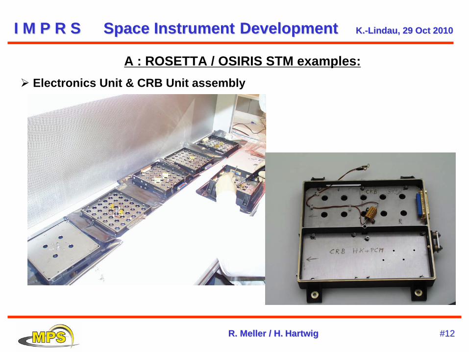
A : ROSETTA / OSIRIS STM examples: Electronics Unit & CRB Unit assembly
I M P R SI M P R S SpaceSpace InstrumentInstrument DevelopmentDevelopment K.K.--LindauLindau, 29 , 29 OctOct 20102010
R. R. MellerMeller / H./ H. HartwigHartwig #12#12
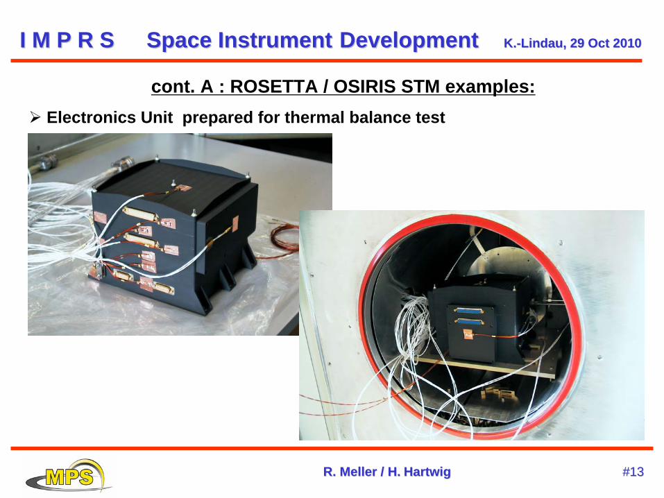
cont. A : ROSETTA / OSIRIS STM examples: Electronics Unit prepared for thermal balance test
I M P R SI M P R S SpaceSpace InstrumentInstrument DevelopmentDevelopment K.K.--LindauLindau, 29 , 29 OctOct 20102010
R. R. MellerMeller / H./ H. HartwigHartwig #13#13
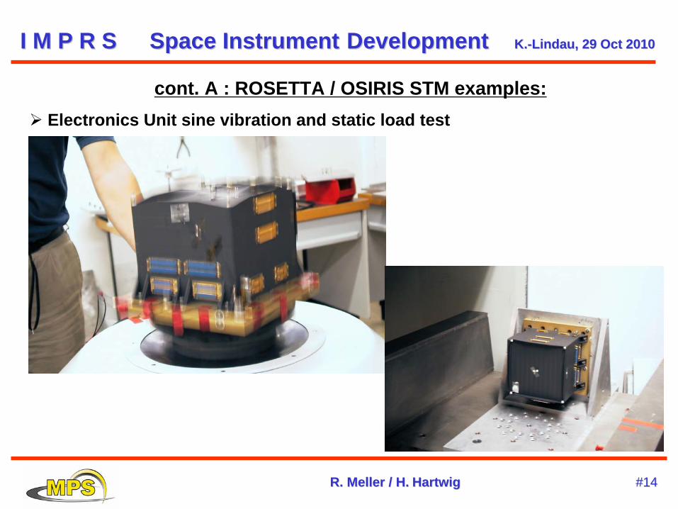
cont. A : ROSETTA / OSIRIS STM examples: Electronics Unit sine vibration and static load test
I M P R SI M P R S SpaceSpace InstrumentInstrument DevelopmentDevelopment K.K.--LindauLindau, 29 , 29 OctOct 20102010
R. R. MellerMeller / H./ H. HartwigHartwig #14#14
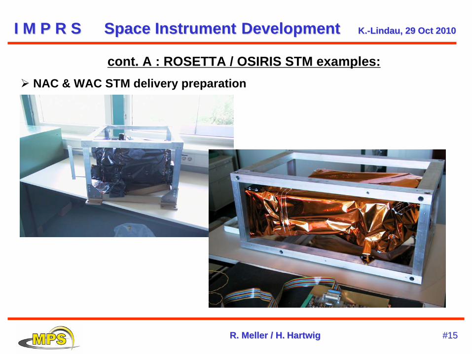
cont. A : ROSETTA / OSIRIS STM examples: NAC & WAC STM delivery preparation
I M P R SI M P R S SpaceSpace InstrumentInstrument DevelopmentDevelopment K.K.--LindauLindau, 29 , 29 OctOct 20102010
R. R. MellerMeller / H./ H. HartwigHartwig #15#15
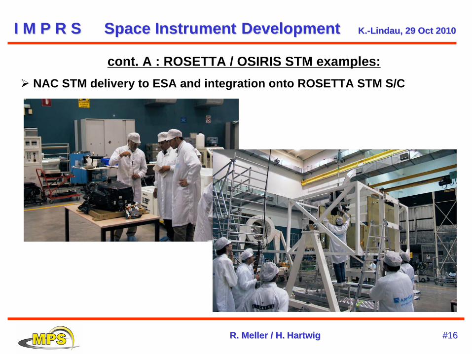
cont. A : ROSETTA / OSIRIS STM examples: NAC STM delivery to ESA and integration onto ROSETTA STM S/C
I M P R SI M P R S SpaceSpace InstrumentInstrument DevelopmentDevelopment K.K.--LindauLindau, 29 , 29 OctOct 20102010
R. R. MellerMeller / H./ H. HartwigHartwig #16#16
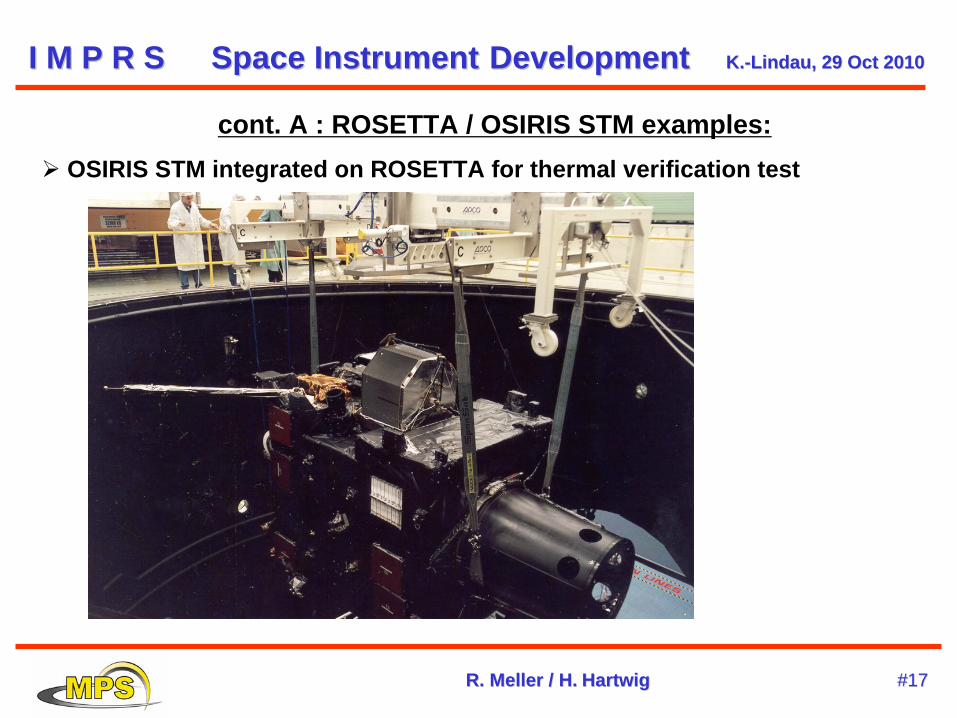
cont. A : ROSETTA / OSIRIS STM examples: OSIRIS STM integrated on ROSETTA for thermal verification test
I M P R SI M P R S SpaceSpace InstrumentInstrument DevelopmentDevelopment K.K.--LindauLindau, 29 , 29 OctOct 20102010
R. R. MellerMeller / H./ H. HartwigHartwig #17#17
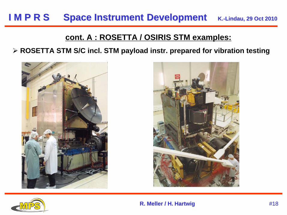
cont. A : ROSETTA / OSIRIS STM examples: ROSETTA STM S/C incl. STM payload instr. prepared for vibration testing
I M P R SI M P R S SpaceSpace InstrumentInstrument DevelopmentDevelopment K.K.--LindauLindau, 29 , 29 OctOct 20102010
R. R. MellerMeller / H./ H. HartwigHartwig #18#18
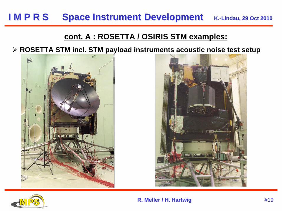
cont. A : ROSETTA / OSIRIS STM examples: ROSETTA STM incl. STM payload instruments acoustic noise test setup
I M P R SI M P R S SpaceSpace InstrumentInstrument DevelopmentDevelopment K.K.--LindauLindau, 29 , 29 OctOct 20102010
R. R. MellerMeller / H./ H. HartwigHartwig #19#19
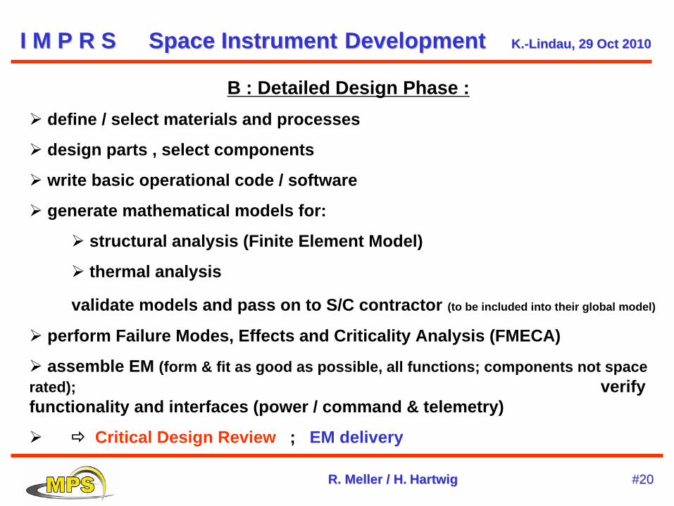
B : Detailed Design Phase : define / select materials and processes
design parts , select components
write basic operational code / software
generate mathematical models for:
structural analysis (Finite Element Model)
thermal analysis
validate models and pass on to S/C contractor (to be included into their global model)
perform Failure Modes, Effects and Criticality Analysis (FMECA)
assemble EM (form & fit as good as possible, all functions; components not space rated); verify functionality and interfaces (power / command & telemetry)
Critical Design Review ; EM delivery
I M P R SI M P R S SpaceSpace InstrumentInstrument DevelopmentDevelopment K.K.--LindauLindau, 29 , 29 OctOct 20102010
R. R. MellerMeller / H./ H. HartwigHartwig #20#20
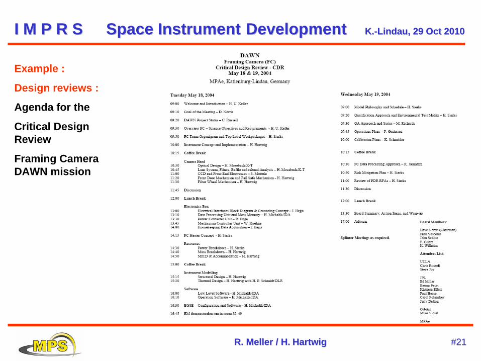
Example :
Design reviews :
Agenda for the
Critical Design Review
Framing Camera DAWN mission
I M P R SI M P R S SpaceSpace InstrumentInstrument DevelopmentDevelopment K.K.--LindauLindau, 29 , 29 OctOct 20102010
R. R. MellerMeller / H./ H. HartwigHartwig #21#21
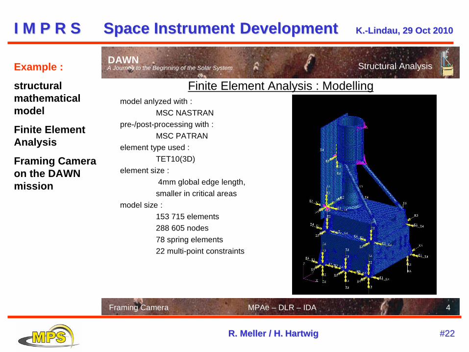
Example :
structural mathematical model
Finite Element Analysis
Framing Camera on the DAWN mission
4
DAWNA Journey to the Beginning of the Solar System
Framing Camera MPAe – DLR – IDA
Structural Analysis
Finite Element Analysis : Modellingmodel anlyzed with :
MSC NASTRANpre-/post-processing with :
MSC PATRANelement type used :
TET10(3D)element size :
4mm global edge length, smaller in critical areas
model size : 153 715 elements288 605 nodes78 spring elements22 multi-point constraints
I M P R SI M P R S SpaceSpace InstrumentInstrument DevelopmentDevelopment K.K.--LindauLindau, 29 , 29 OctOct 20102010
R. R. MellerMeller / H./ H. HartwigHartwig #22#22
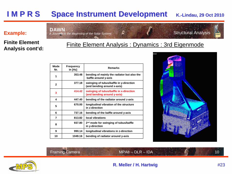
Example:
Finite Element Analysis cont‘d:
10
DAWNA Journey to the Beginning of the Solar System
Framing Camera MPAe – DLR – IDA
Structural Analysis
Finite Element Analysis : Dynamics : 3rd Eigenmode
bending of radiator around y-axis1049.1610
longitudinal vibrations in z-direction990.149
2nd mode for swinging of tubus/baffle in y-direction
937.808
local vibrations813.827
bending of the baffle around y-axis737.166
longitudinal vibration of the structure in z-direction
670.005
bending of the radiator around z-axis447.404
swinging of tubus/baffle in x-direction(and bending around y-axis)
414.423
swinging of tubus/baffle in y-direction(and bending around x-axis)
377.182
bending of mainly the radiator but also thebaffle around y-axis
353.481
RemarksFrequencyin [Hz]
ModeNr.
I M P R SI M P R S SpaceSpace InstrumentInstrument DevelopmentDevelopment K.K.--LindauLindau, 29 , 29 OctOct 20102010
R. R. MellerMeller / H./ H. HartwigHartwig #23#23
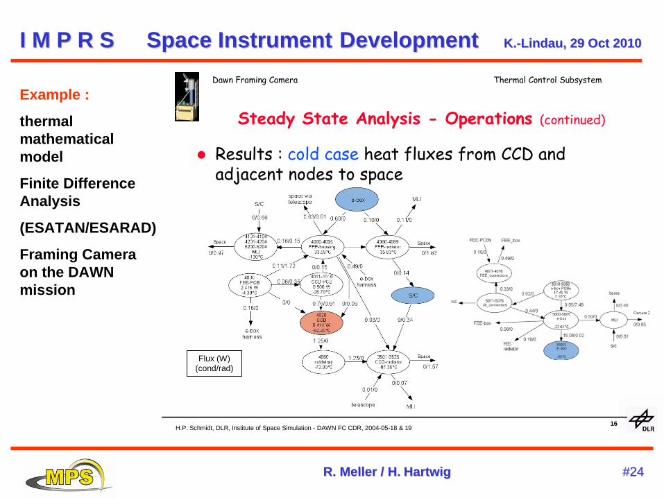
H.P. Schmidt, DLR, Institute of Space Simulation - DAWN FC CDR, 2004-05-18 & 1916
Dawn Framing Camera Thermal Control Subsystem
Steady State Analysis - Operations (continued)
Results : cold case heat fluxes from CCD and adjacent nodes to space
Flux (W)(cond/rad)
Example :
thermal mathematical model
Finite Difference Analysis
(ESATAN/ESARAD)
Framing Camera on the DAWN mission
I M P R SI M P R S SpaceSpace InstrumentInstrument DevelopmentDevelopment K.K.--LindauLindau, 29 , 29 OctOct 20102010
R. R. MellerMeller / H./ H. HartwigHartwig #24#24
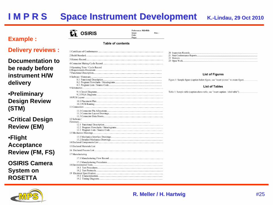
Example :
Delivery reviews :
Documentation to be ready before instrument H/W delivery
•Preliminary Design Review (STM)
•Critical Design Review (EM)
•Flight Acceptance Review (FM, FS)
OSIRIS Camera System on ROSETTA
I M P R SI M P R S SpaceSpace InstrumentInstrument DevelopmentDevelopment K.K.--LindauLindau, 29 , 29 OctOct 20102010
R. R. MellerMeller / H./ H. HartwigHartwig #25#25
C / D :Assembly / Integration / Verification :
Controlled and documented flight parts production & procurement; population of Printed Circuit Boards; in Clean Room ; ESD protected etc
Testing at subsystem and system level:
Functional tests , including S/C interface verification (with S/C simulator) Performance Tests / Calibration Environmental tests :
Vibration Pyro-Shock Thermal-Vacuum / Thermal- Balance Mechanism Lifetime Electro-Magnetic Compatibility (EMC)
Physical properties Interface Metrology Mass Center of Gravity Moments of Inertia
I M P R SI M P R S SpaceSpace InstrumentInstrument DevelopmentDevelopment K.K.--LindauLindau, 29 , 29 OctOct 20102010
R. R. MellerMeller / H./ H. HartwigHartwig #26#26
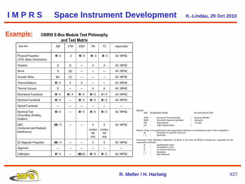
Example:
I M P R SI M P R S SpaceSpace InstrumentInstrument DevelopmentDevelopment K.K.--LindauLindau, 29 , 29 OctOct 20102010
R. R. MellerMeller / H./ H. HartwigHartwig #27#27
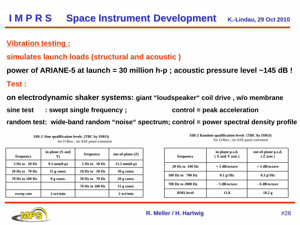
Vibration testing :
simulates launch loads (structural and acoustic )
power of ARIANE-5 at launch = 30 million h-p ; acoustic pressure level ~145 dB !
Test :
on electrodynamic shaker systems: giant “loudspeaker“ coil drive , w/o membrane
sine test : swept single frequency ; control = peak acceleration
random test: wide-band random “noise“ spectrum; control = power spectral density profile
SIR-2 Sine qualification levels (TBC by ISRO)for O-Box ; on ASS panel extension
frequencyin-plane (X and
Y) frequency out-of-plane (Z)
5 Hz to 20 Hz 9.3 mm(0-p) 5 Hz to 18 Hz 11.5 mm(0-p)
20 Hz to 70 Hz 15 g const. 18 Hz to 50 Hz 30 g const.
70 Hz to 100 Hz 8 g const. 50 Hz to 70 Hz 20 g const.
70 Hz to 100 Hz 15 g const.
sweep rate 2 oct/min 2 oct/min
SIR-2 Random qualification levels (TBC by ISRO)for O-Box ; on ASS panel extension
frequencyin-plane p.s.d.
( X and Y axis )out-of-plane p.s.d.
( Z axis )
20 Hz to 100 Hz + 3 dB/octave + 3 dB/octave
100 Hz to 700 Hz 0.1 g²/Hz 0.3 g²/Hz
700 Hz to 2000 Hz - 3 dB/octave - 6 dB/octave
RMS level 11.8 18.2 g
I M P R SI M P R S SpaceSpace InstrumentInstrument DevelopmentDevelopment K.K.--LindauLindau, 29 , 29 OctOct 20102010
R. R. MellerMeller / H./ H. HartwigHartwig #28#28
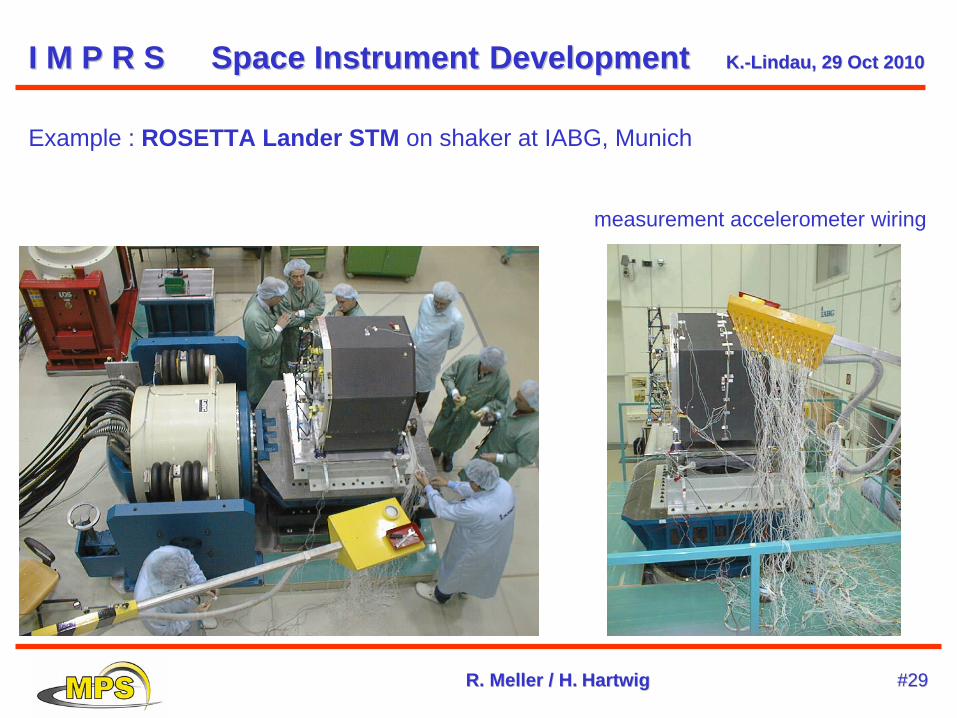
Example : ROSETTA Lander STM on shaker at IABG, Munich
measurement accelerometer wiring
I M P R SI M P R S SpaceSpace InstrumentInstrument DevelopmentDevelopment K.K.--LindauLindau, 29 , 29 OctOct 20102010
R. R. MellerMeller / H./ H. HartwigHartwig #29#29
Thermal Vacuum / Thermal Balance Test :
tests thermal behaviour in special test chambers under space conditions
(high vacuum ; cold space ; solar illumination / planetary thermal emission)
passive protective systems:
Multi-Layer Insulation (MLI) ;
thermal radiators / absorbers
second-surface mirrors (reject heat against solar irradiation)
active protective systems :
heaters (electrical or radoactive)
coolers (Stirling)
capillary heat pipes (zero-g)
I M P R SI M P R S SpaceSpace InstrumentInstrument DevelopmentDevelopment K.K.--LindauLindau, 29 , 29 OctOct 20102010
R. R. MellerMeller / H./ H. HartwigHartwig #30#30
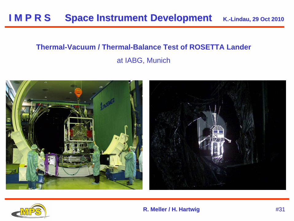
Thermal-Vacuum / Thermal-Balance Test of ROSETTA Lander
at IABG, Munich
I M P R SI M P R S SpaceSpace InstrumentInstrument DevelopmentDevelopment K.K.--LindauLindau, 29 , 29 OctOct 20102010
R. R. MellerMeller / H./ H. HartwigHartwig #31#31
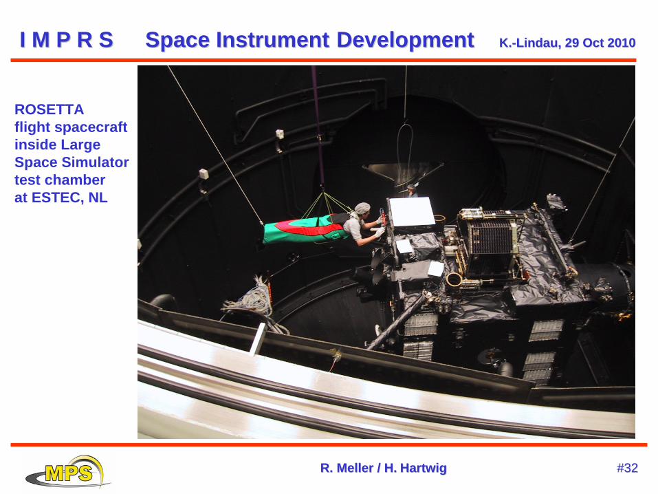
AROSETTA flight spacecraft inside Large Space Simulator test chamber at ESTEC, NL
I M P R SI M P R S SpaceSpace InstrumentInstrument DevelopmentDevelopment K.K.--LindauLindau, 29 , 29 OctOct 20102010
R. R. MellerMeller / H./ H. HartwigHartwig #32#32
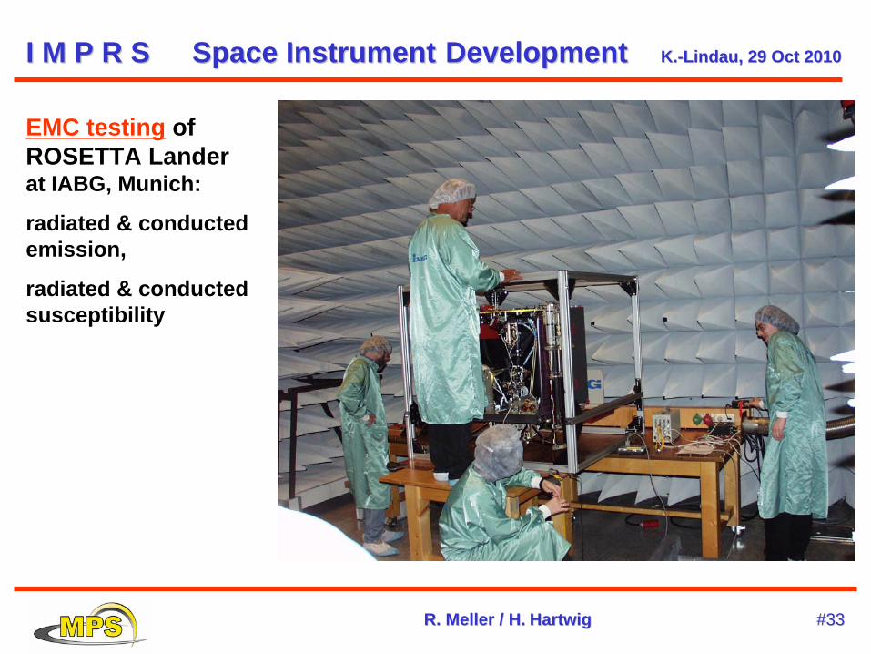
EMC testing of ROSETTA Lander at IABG, Munich:
radiated & conducted emission,
radiated & conducted susceptibility
I M P R SI M P R S SpaceSpace InstrumentInstrument DevelopmentDevelopment K.K.--LindauLindau, 29 , 29 OctOct 20102010
R. R. MellerMeller / H./ H. HartwigHartwig #33#33
SUMMARY & General Recommendations :
Keep track of requirement flowdown !
Assemble (and maintain!) a good technical team !
Start design with resource margins (25% min.) !
Take design reviews serious – they help you !
Nurse back-up solutions along with the main development !
Keep documentation up-to-date !!! - you need it after launch!
Test – test – test !!! (but don‘t overstress the Flight Unit !)
Hold post-delivery “Lessons Learned“ review with your team !
I M P R SI M P R S SpaceSpace InstrumentInstrument DevelopmentDevelopment K.K.--LindauLindau, 29 , 29 OctOct 20102010
R. R. MellerMeller / H./ H. HartwigHartwig #34#34