Embed Size (px)
Citation preview
w w w . a u t o s t e e l . o r g
Improving the Life of High-Strength Steel Stamping Dies
Report on A/SP Tribology Team Die Wear Study
Alan D. Pearson, General Motors CorporationGreg Dalton, TribSys
w w w . a u t o s t e e l . o r g
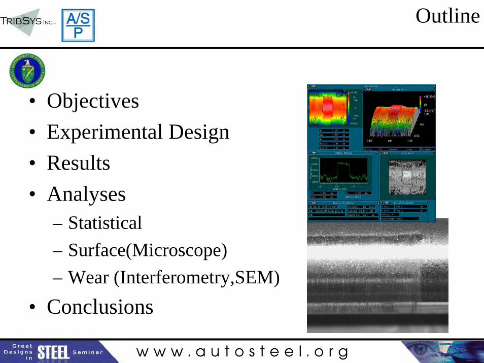
Outline
• Objectives• Experimental Design• Results• Analyses
– Statistical– Surface(Microscope)– Wear (Interferometry,SEM)
• Conclusions

w w w . a u t o s t e e l . o r g
Objectives
• Support the implementation of AHSS initiatives.• Study die wear issues in a controlled environment• Investigate strategies for improving die life.• Develop an understanding of die wear with
AHSS to help anticipate and deal with problems.• Die wear study - 48,000 “parts” with 16 different
conditions for a total of 768,000 parts.
w w w . a u t o s t e e l . o r g
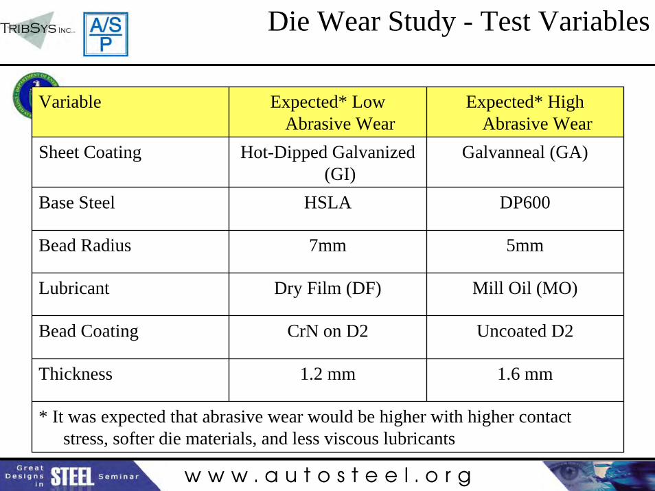
Die Wear Study - Test Variables
Variable Expected* Low Abrasive Wear
Expected* High Abrasive Wear
Sheet Coating Hot-Dipped Galvanized (GI)
Galvanneal (GA)
Base Steel HSLA DP600
Bead Radius 7mm 5mm
Lubricant Dry Film (DF) Mill Oil (MO)
Bead Coating CrN on D2 Uncoated D2
Thickness 1.2 mm 1.6 mm
* It was expected that abrasive wear would be higher with higher contact stress, softer die materials, and less viscous lubricants
w w w . a u t o s t e e l . o r g
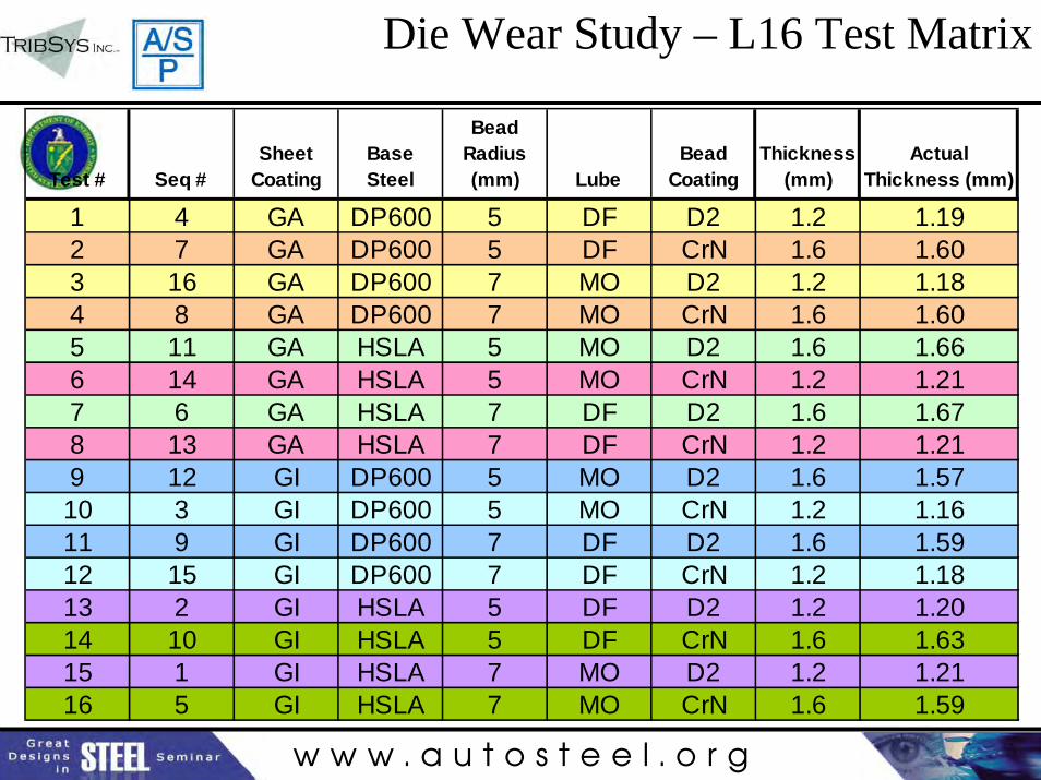
Test # Seq #Sheet
CoatingBase Steel
Bead Radius (mm) Lube
Bead Coating
Thickness (mm)
Actual Thickness (mm)
1 4 GA DP600 5 DF D2 1.2 1.192 7 GA DP600 5 DF CrN 1.6 1.603 16 GA DP600 7 MO D2 1.2 1.184 8 GA DP600 7 MO CrN 1.6 1.605 11 GA HSLA 5 MO D2 1.6 1.666 14 GA HSLA 5 MO CrN 1.2 1.217 6 GA HSLA 7 DF D2 1.6 1.678 13 GA HSLA 7 DF CrN 1.2 1.219 12 GI DP600 5 MO D2 1.6 1.5710 3 GI DP600 5 MO CrN 1.2 1.1611 9 GI DP600 7 DF D2 1.6 1.5912 15 GI DP600 7 DF CrN 1.2 1.1813 2 GI HSLA 5 DF D2 1.2 1.2014 10 GI HSLA 5 DF CrN 1.6 1.6315 1 GI HSLA 7 MO D2 1.2 1.2116 5 GI HSLA 7 MO CrN 1.6 1.59
Die Wear Study – L16 Test Matrix
w w w . a u t o s t e e l . o r g
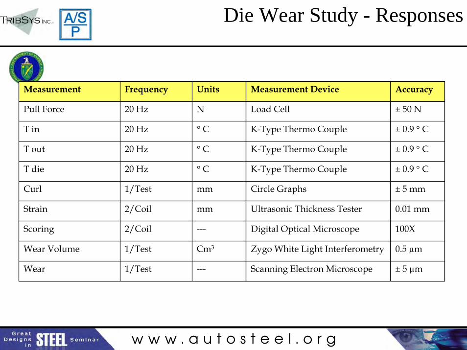
Die Wear Study - Responses
Measurement Frequency Units Measurement Device Accuracy
Pull Force 20 Hz N Load Cell ± 50 N
T in 20 Hz ° C K-Type Thermo Couple ± 0.9 ° C
T out 20 Hz ° C K-Type Thermo Couple ± 0.9 ° C
T die 20 Hz ° C K-Type Thermo Couple ± 0.9 ° C
Curl 1/Test mm Circle Graphs ± 5 mm
Strain 2/Coil mm Ultrasonic Thickness Tester 0.01 mm
Scoring 2/Coil --- Digital Optical Microscope 100X
Wear Volume 1/Test Cm3 Zygo White Light Interferometry 0.5 µm
Wear 1/Test --- Scanning Electron Microscope ± 5 µm
w w w . a u t o s t e e l . o r g
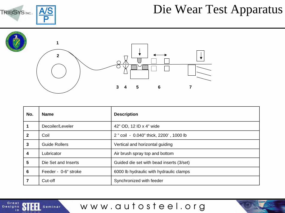
Die Wear Test Apparatus
1
2
3 4 65 7
No. Name Description
1 Decoiler/Leveler 42” OD, 12 ID x 4” wide
2 Coil 2 ” coil - 0.040” thick, 2200’ , 1000 lb
3 Guide Rollers Vertical and horizontal guiding
4 Lubricator Air brush spray top and bottom
5 Die Set and Inserts Guided die set with bead inserts (3/set)
6 Feeder - 0-6“ stroke 6000 lb hydraulic with hydraulic clamps
7 Cut-off Synchronized with feeder
w w w . a u t o s t e e l . o r g
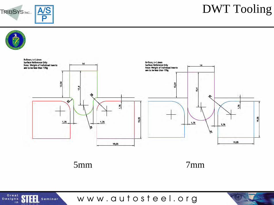
DWT Tooling
5mm 7mm
w w w . a u t o s t e e l . o r g
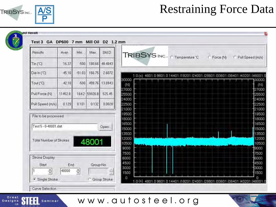
Restraining Force Data
Test 3 GA DP600 7 mm Mill Oil D2 1.2 mm
w w w . a u t o s t e e l . o r g
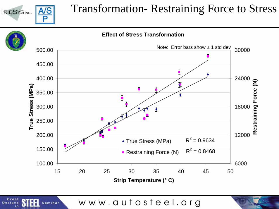
Transformation- Restraining Force to Stress
Effect of Stress Transformation
R2 = 0.8468
R2 = 0.9634
100.00
150.00
200.00
250.00
300.00
350.00
400.00
450.00
500.00
15 20 25 30 35 40 45 50Strip Temperature (° C)
True
Str
ess
(MPa
)
6000
12000
18000
24000
30000
Res
trai
ning
For
ce (N
)
True Stress (MPa)
Restraining Force (N)
Note: Error bars show ± 1 std dev
w w w . a u t o s t e e l . o r g
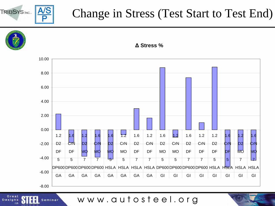
Change in Stress (Test Start to Test End)
Δ Stress %
-8.00
-6.00
-4.00
-2.00
0.00
2.00
4.00
6.00
8.00
10.00
1.2 1.6 1.2 1.6 1.6 1.2 1.6 1.2 1.6 1.2 1.6 1.2 1.2 1.6 1.2 1.6
D2 CrN D2 CrN D2 CrN D2 CrN D2 CrN D2 CrN D2 CrN D2 CrN
DF DF MO MO MO MO DF DF MO MO DF DF DF DF MO MO
5 5 7 7 5 5 7 7 5 5 7 7 5 5 7 7
DP600 DP600 DP600 DP600 HSLA HSLA HSLA HSLA DP600 DP600 DP600 DP600 HSLA HSLA HSLA HSLA
GA GA GA GA GA GA GA GA GI GI GI GI GI GI GI GI
w w w . a u t o s t e e l . o r g
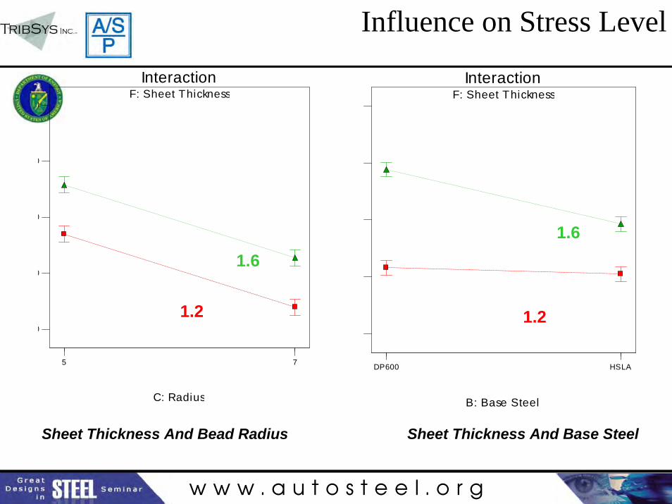
Influence on Stress Level
F: Sheet Thickness
5 7
Interaction
C: Radius
0
0
0
0
0F: Sheet Thickness
DP600 HSLA
Interaction
B: Base Steel
Sheet Thickness And Bead Radius Sheet Thickness And Base Steel
1.2
1.6
1.2
1.6
w w w . a u t o s t e e l . o r g
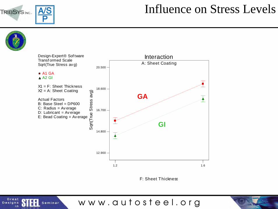
Influence on Stress Levels
Design-Expert® Sof twareTransf ormed ScaleSqrt(True Stress av g)
A1 GAA2 GI
X1 = F: Sheet ThicknessX2 = A: Sheet Coating
Actual FactorsB: Base Steel = DP600C: Radius = Av erageD: Lubricant = Av erageE: Bead Coating = Av erage
A: Sheet Coating
1.2 1.6
Interaction
F: Sheet Thickness
Sqr
t(Tru
e S
tress
avg
)
12.900
14.800
16.700
18.600
20.500
GA
GI
w w w . a u t o s t e e l . o r g
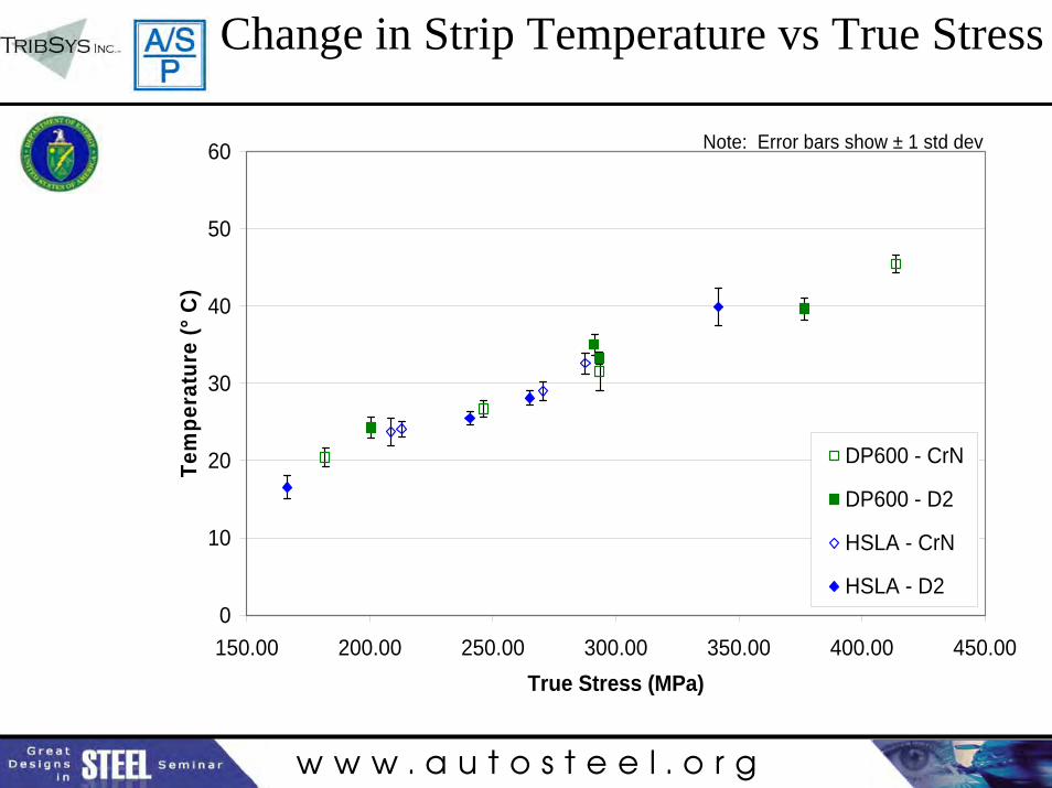
0
10
20
30
40
50
60
150.00 200.00 250.00 300.00 350.00 400.00 450.00True Stress (MPa)
Tem
pera
ture
(° C
)
DP600 - CrN
DP600 - D2
HSLA - CrN
HSLA - D2
Note: Error bars show ± 1 std dev
Change in Strip Temperature vs True Stress
w w w . a u t o s t e e l . o r g
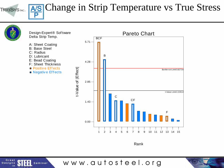
Change in Strip Temperature vs True Stress
Design-Expert® Sof twareDelta Strip Temp.
A: Sheet CoatingB: Base SteelC: RadiusD: LubricantE: Bead CoatingF: Sheet Thickness
Positiv e Ef f ects Negativ e Ef f ects
Pareto Chart
t-Val
ue o
f |E
ffect
|
Rank
0.00
1.43
2.85
4.28
5.71
Bonferroni Limit 3.82734
t-Value Limit 2.22814
1 2 3 4 5 6 7 8 9 10 11 12 13 14 15
BCF
B
CCF
F
w w w . a u t o s t e e l . o r g
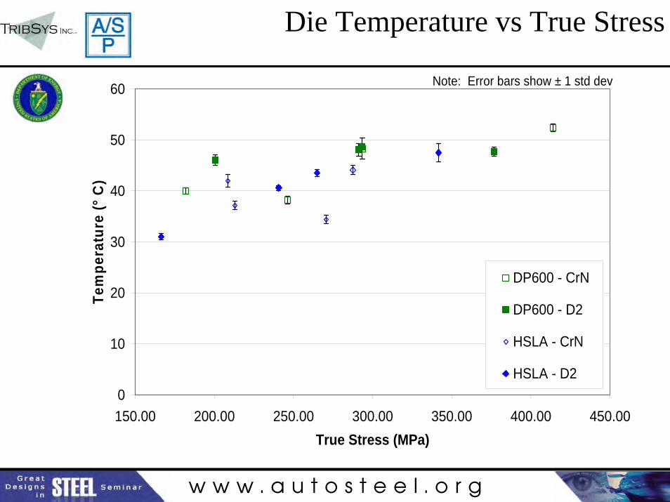
Die Temperature vs True Stress
0
10
20
30
40
50
60
150.00 200.00 250.00 300.00 350.00 400.00 450.00True Stress (MPa)
Tem
pera
ture
(° C
)
DP600 - CrN
DP600 - D2
HSLA - CrN
HSLA - D2
Note: Error bars show ± 1 std dev

w w w . a u t o s t e e l . o r g
Die Temperature vs True Stress
0
10
20
30
40
50
60
150.00 200.00 250.00 300.00 350.00 400.00 450.00True Stress (MPa)
Tem
pera
ture
(° C
)
DP600 - CrN
DP600 - D2
HSLA - CrN
HSLA - D2
Note: Error bars show ± 1 std dev
w w w . a u t o s t e e l . o r g
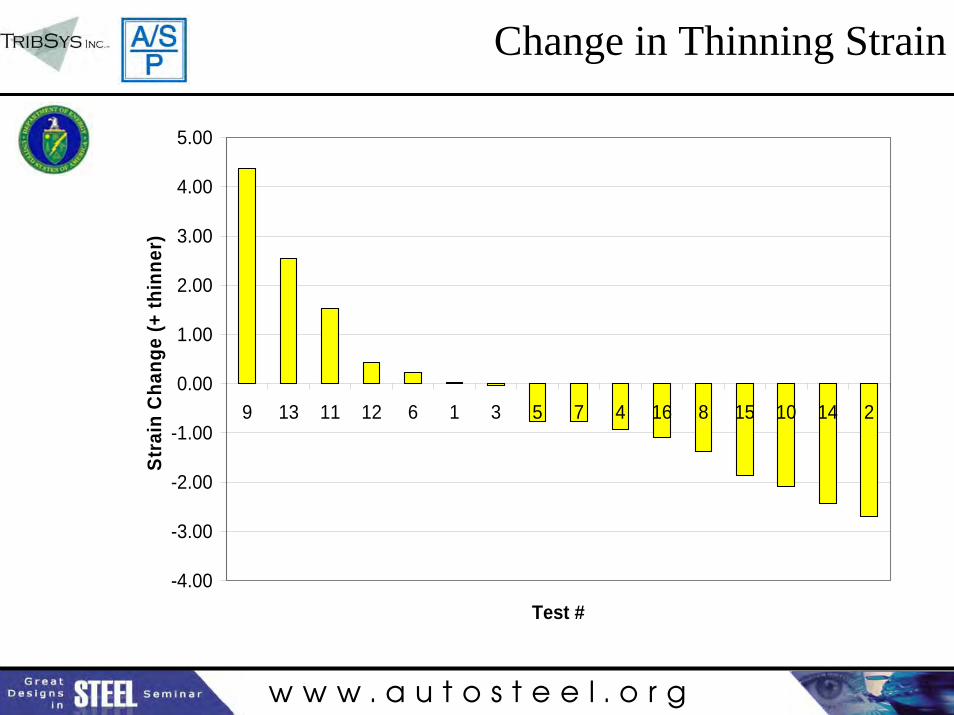
Change in Thinning Strain
-4.00
-3.00
-2.00
-1.00
0.00
1.00
2.00
3.00
4.00
5.00
9 13 11 12 6 1 3 5 7 4 16 8 15 10 14 2
Test #
Stra
in C
hang
e (+
thin
ner)
w w w . a u t o s t e e l . o r g
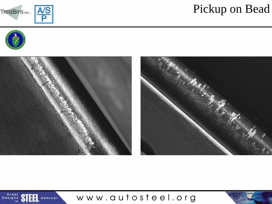
Pickup on Bead
w w w . a u t o s t e e l . o r g
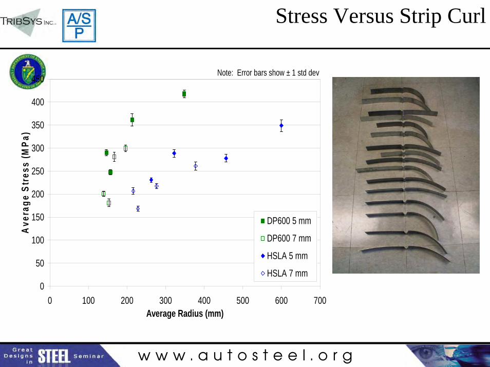
Stress Versus Strip Curl
0
50
100
150
200
250
300
350
400
450
0 100 200 300 400 500 600 700Average Radius (mm)
Ave
rage
Str
ess
(MPa
)
DP600 5 mm
DP600 7 mm
HSLA 5 mm
HSLA 7 mm
Note: Error bars show ± 1 std dev
w w w . a u t o s t e e l . o r g
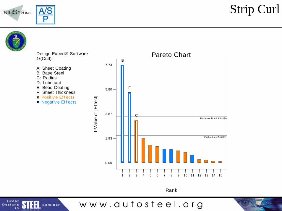
Strip Curl
Design-Expert® Sof tware1/(Curl)
A: Sheet CoatingB: Base SteelC: RadiusD: LubricantE: Bead CoatingF: Sheet Thickness
Positiv e Ef f ects Negativ e Ef f ects
Pareto Chart
t-Val
ue o
f |E
ffect
|
Rank
0.00
1.93
3.87
5.80
7.73
Bonferroni Limit 3.64889
t-Value Limit 2.17881
1 2 3 4 5 6 7 8 9 10 11 12 13 14 15
B
F
C
w w w . a u t o s t e e l . o r g
R
h
θ
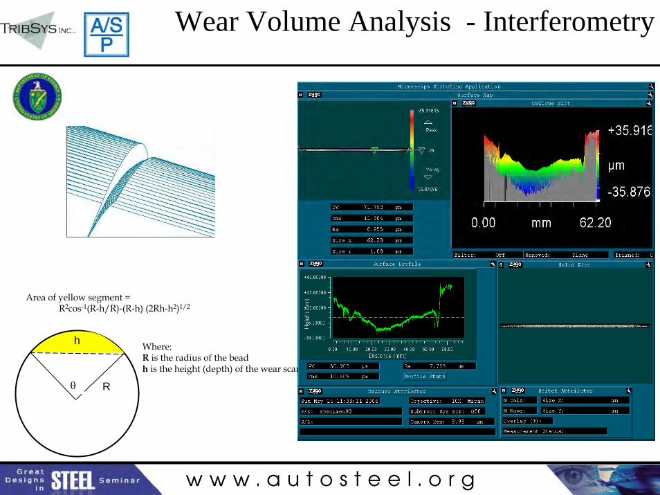
Area of yellow segment = R2cos-1(R-h/R)-(R-h) (2Rh-h2)1/2
Where:R is the radius of the bead h is the height (depth) of the wear scar
Wear Volume Analysis - Interferometry
w w w . a u t o s t e e l . o r g
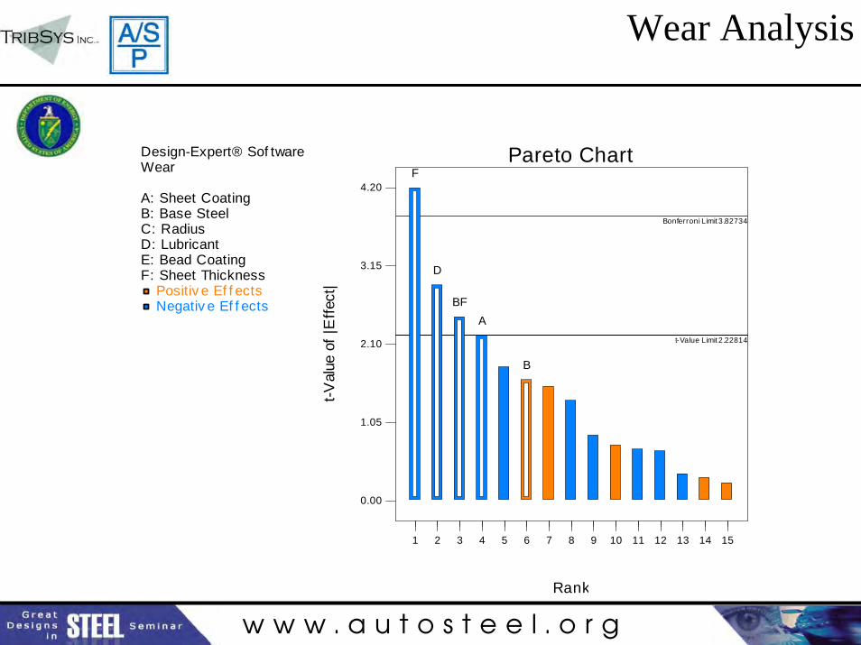
Wear Analysis
Design-Expert® Sof twareWear
A: Sheet CoatingB: Base SteelC: RadiusD: LubricantE: Bead CoatingF: Sheet Thickness
Positiv e Ef f ects Negativ e Ef f ects
Pareto Chart
t-Val
ue o
f |E
ffect
|
Rank
0.00
1.05
2.10
3.15
4.20
Bonferroni Limit 3.82734
t-Value Limit 2.22814
1 2 3 4 5 6 7 8 9 10 11 12 13 14 15
F
D
BFA
B
w w w . a u t o s t e e l . o r g
Observations
• Highest wear with lower strength (HSLA), thinner sheet (1.2), and liquid lubricant (MO)
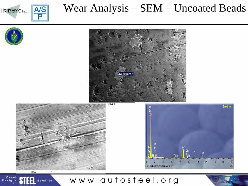
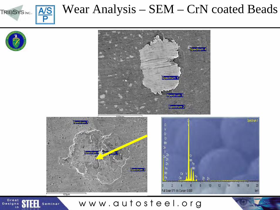
• Less abrasive wear with CrN than with D2• CrN showed spalling (Fatigue wear)• GA less pickup than GI (only test 5 had PU) also
noted in Phase 3• Die and strip temperature higher with GA than GI• Die and strip temperature higher with DP600 than
HSLA.
w w w . a u t o s t e e l . o r g
Wear Analysis – SEM – Uncoated Beads
w w w . a u t o s t e e l . o r g
Wear Analysis – SEM – CrN coated Beads
w w w . a u t o s t e e l . o r g
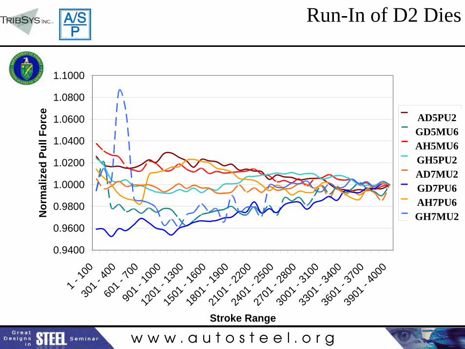
Run-In of D2 Dies
0.9400
0.9600
0.9800
1.0000
1.0200
1.0400
1.0600
1.0800
1.1000
1 - 10
030
1 - 40
060
1 - 70
090
1 - 10
0012
01 - 1
300
1501
- 160
018
01 - 1
900
2101
- 220
024
01 - 2
500
2701
- 280
030
01 - 3
100
3301
- 340
036
01 - 3
700
3901
- 400
0
Stroke Range
Nor
mal
ized
Pul
l For
ce Test 1Test 9Test 5Test 13Test 3Test 11Test 7Test 15
AD5PU2GD5MU6AH5MU6GH5PU2AD7MU2GD7PU6AH7PU6GH7MU2
w w w . a u t o s t e e l . o r g
0.9400
0.9600
0.9800
1.0000
1.0200
1.0400
1.0600
1.0800
1.1000
1 - 10
030
1 - 40
060
1 - 70
090
1 - 10
0012
01 - 1
300
1501
- 160
018
01 - 1
900
2101
- 220
024
01 - 2
500
2701
- 280
030
01 - 3
100
3301
- 340
036
01 - 3
700
3901
- 400
0
Stroke Range
Nor
mal
ized
Pul
l For
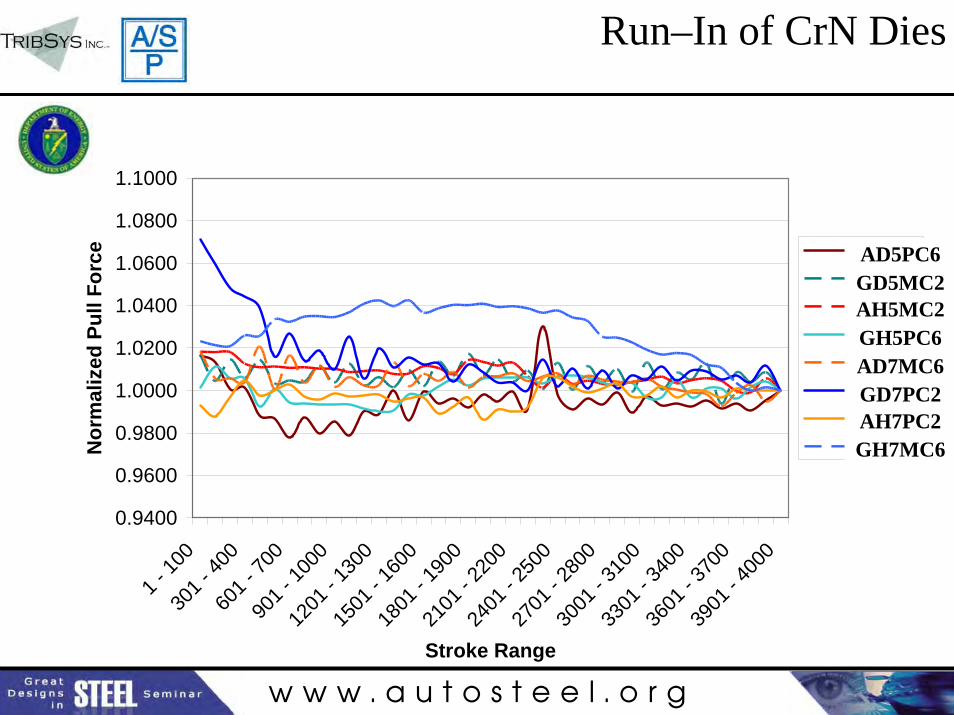
ce Test 2Test 10Test 6Test 14Test 4Test 12Test 8Test 16
Run–In of CrN Dies
AD5PC6GD5MC2AH5MC2GH5PC6AD7MC6GD7PC2AH7PC2GH7MC6
w w w . a u t o s t e e l . o r g
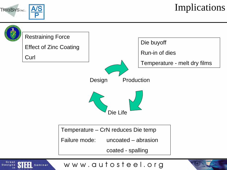
Implications
Production
Die Life
Design
Restraining Force
Effect of Zinc Coating
Curl
Temperature – CrN reduces Die temp
Failure mode: uncoated – abrasion
coated - spalling
Die buyoff
Run-in of dies
Temperature - melt dry films

w w w . a u t o s t e e l . o r g
Conclusions
• Restraining force or stress is most influenced by sheet thickness and bead radius. Somewhat surprisingly, sheet coating, was alsofound to be a significant factor.
• Thinning strains confirm the stress factors.• A significant interaction was found between base steel and
thickness: the strain difference between the HSLA and DP600 increases as sheet thickness increases.
• Wear volume measurements shows both abrasive and adhesive wear. The type of wear was generally related to the type of bead coating.
• In general adhesion was heaviest with the galvanized sheet whileabrasion was heaviest with the galvanneal sheet.
• The effect of wear on restraining force and thinning strain was not directly related to one type of wear but more on the nature of the worn surface with pickup generally increasing restraining force.
w w w . a u t o s t e e l . o r g
Conclusions
• Unexpectedly, abrasive wear did not in many cases lead to reduced restraining force rather restraining force increased with increased abrasive wear.
• These results appear to be sensitive to bead material with the uncoated D2 showing the strongest tendency for increased restraining force with increased abrasive wear.
• The effectiveness of the wax-based DFL was less than expected possibly due to melting.
• Run-in during the initial 4000 strokes was plotted and shows a significant variation in restraining force during the run in phase.
• The restraining force with the CrN coated beads achieved stability much sooner than with the uncoated D2 beads.
w w w . a u t o s t e e l . o r g
Future Work
• Conduct one factor at a time testing– Cast Steel Die Material (S0050A)– DP 980– DP 780– TRIP 780– Galvanized/Galvanneal