Embed Size (px)
Citation preview
Paper ID #25533
Improving Students’ Understanding of Electromagnetic Principles with anAlternator Design-Build-Test Project
Dr. Matthew R. Aldeman, Illinois State University
Matt Aldeman is an Assistant Professor of Technology at Illinois State University, where he teaches inthe Renewable Energy and Engineering Technology programs. Matt joined the Technology departmentfaculty after working at the Illinois State University Center for Renewable Energy for over five years.Previously, he worked at General Electric as a wind site manager at the Grand Ridge and Rail Splitterwind projects. Matt’s experience also includes service in the U.S. Navy as a nuclear propulsion officerand leader of the Reactor Electrical division on the aircraft carrier USS John C. Stennis. Matt is anhonors graduate of the U.S. Naval Nuclear Power School and holds a B.S. in Mechanical Engineeringfrom Northwestern University, a Master of Engineering Management from Old Dominion University, anda Ph.D. in Mechanical and Aerospace Engineering from the Illinois Institute of Technology.
c©American Society for Engineering Education, 2019
Improving Students’ Understanding of Electromagnetic Principles with an
Alternator Design-Build-Test Project
Matthew R. Aldeman Illinois State University, Dept. of Technology, Normal, IL, 61790
As a required course in the Renewable Energy undergraduate major at Illinois State
University, students take TEC 259: Power Generation: Production, Conversion and Storage,
typically in their junior or senior years. The course covers the fundamental laws governing
energy conversion and includes practical applications relating to the design of energy conversion
systems. Over an approximately one-month period in the latter half of the course, students
design, build, and test their own AC electric alternator or generator. During this time the class
lectures include a discussion of electromagnetic principles, Faraday’s Law, and real-world
generator designs. For materials, students are given a block of wood, wooden dowel rods, shelf
support brackets, screws, pairs of ceramic and neodymium magnets, and thirty feet of 24 AWG
magnet wire. Students are encouraged to iteratively test and improve their designs. The
generators are tested by attaching an electric drill to the input shaft of the generator, and the
output is measured with an oscilloscope. The design objective is to maximize the output voltage
of the machine. After some experimentation, the instructor for the course has set a benchmark of
300 mV as the target voltage output. Some students have achieved output voltages of more than
3V. The assessment method consists of two parts: i) a quantitative assessment of the machine’s
output voltage compared to the 300 mV benchmark, and ii) a qualitative assessment of the
durability and reliability of the machine. Students have given very positive feedback on the
project, saying that it was their favorite part of the course, and have commented that the project
greatly improved their understanding of electromagnetic principles and electric machine design.
The students’ exam scores on related material also show marked signs of improvement.
Introduction and Background
A Bachelor of Science in Renewable Energy (RE) degree program was established by
Illinois State University in 2007, and is housed within the Department of Technology. The
degree was initially offered in two specialization sequences: i. Technical, and ii.
Economics/Public Policy. The two sequences were combined in 2013, and students are now
required to choose a minor in one of the following areas: Business Administration, Politics and
Government, Economics, Environmental Studies, Geography, and Technology.
The mission of the Renewable Energy program at Illinois State University is “To prepare
technically-oriented managerial professionals and leaders for business, industry, government,
and education by articulating and integrating competencies in Renewable Energy.” The program
prepares graduates for jobs in the fields of renewable energy systems as well as regulatory and
governmental agencies. To meet this demand for well-rounded graduates who are
knowledgeable in both technical and economic aspects of renewable energy systems, a
curriculum has been developed consisting of courses from the Departments of Technology,
Economics, Physics, Business, and others.
The Renewable Energy Program operates on five goals that align with the strategic goals
of the college and university. The five goals of the Renewable Energy program are:
1. Provide students with high quality educational experiences by featuring a modern, up-to-
date curriculum that will develop the technical and managerial knowledge, skills, and
attitudes that are foundational to success as RE professionals.
2. Recruit and graduate a diverse group of individuals to support companies and
organizations that will employ RE professionals in the state and throughout the United
States.
3. Provide opportunities for students to interface with RE professionals.
4. Provide service to companies and organizations that employ RE graduates through
applied research, consulting/workshops, and participation in professional organizations.
5. Develop industry and RE alumni relationships in support of the program.
To meet Program Goal #1 and ensure that graduates acquire a fundamental understanding
of both conventional and renewable power plant systems, a new required course was added for
the spring semester of 2017 called TEC 259: Power Generation: Production, Conversion and
Storage. The course is typically taken by students in their junior or senior years. The purpose of
this course is to help students understand the operating principles of many types of electrical
generation power plants. The principles are applicable to most types of conventional fossil-fuel
based thermal power plants as well as thermal renewable energy power plants such as solar
thermal or geothermal plants.
The first half of the course focuses on thermal energy, beginning with a review of the
fundamentals of work, energy, and power, followed by applications of the Laws of
Thermodynamics, with particular emphasis on the First and Second Laws of Thermodynamics
and their implications for thermal energy power plants. Next, the course turns to the topic of
heat transfer, with an emphasis on Steam Cycles and calculation of heat flux through conduction,
convection, radiation, and combined modes of heat transfer.
The second half of the semester takes a turn away from thermal energy processes and
moves towards the electrical generation aspect of electric generation power plants. The second
half of the semester is applicable to all of the previously-mentioned types of power plants, and is
also applicable to wind turbines. The electrical generation section of the course includes the
topics of magnetism and electromagnetism, induced voltage (Faraday’s Law), and the many
variations of generators that are in use today (e.g. synchronous, induction, permanent magnet,
doubly-fed induction, full-converter, etc.). The final topic in the class is energy storage.
Several storage options are discussed, including traditional electro-chemical batteries of various
chemistries, pumped hydro and other gravitational energy storage, flywheels, and compressed
gas. A topical outline is given below.
TEC 259: Power Generation: Production, Conversion and Storage
I. Basic Principles of Energy Conversion
A. Work, Energy, Power
B. Types of Energy Production, Storage, and Conversion
C. Laws of Thermodynamics
II. Thermal Energy Conversion
A. Steam Cycles & Turbines
B. Thermal Energy Transfer: Conduction, Convection and Radiation
C. Heat Exchangers, Boilers & Condensers
III. Electrical Energy Conversion
A. Review of electrical fundamentals
B. Induced Voltage and Faraday’s Law
C. Alternators and Generators
IV. Energy Storage
A. Electro-chemical Batteries
B. Pumped Hydro
C. Flywheels
D. Compressed Gas
Students in this class are assigned approximately 18 homework assignments during the
semester. The homework assignments are short, and are intended to take students approximately
30 minutes to complete outside of class. However, in keeping with the applied nature of this
course, the instructor (and author of the present paper) desired to find a hands-on project that
would allow the students to apply some of the important principles from the course. The hands-
on project should reinforce the topics discussed in class, should be fun, and should allow for
friendly competition between the students.
There are a variety of energy-related projects that have been developed for high school
and college level classrooms. For example, the NEED Project offers an entire curriculum of K-
12 energy education lessons and projects [1]. The KidWind Project, meanwhile, developed a set
of interactive wind energy kits [2] and, in collaboration with the National Renewable Energy
Laboratory (NREL) and the U.S. Department of Energy, led the development of the annual U.S.
Collegiate Wind Competition [3]. The website Sciencing has developed a tutorial for students to
build homemade electric generators [4], and the website teacherstryscience.org has developed a
tutorial lesson plan around constructing a wind turbine generator [5]. The Electrical
Construction & Maintenance magazine recently reported that a Florida high school student has
utilized these same principles to develop a $12 hydroelectric turbine generator made out of
recyclable materials [6]. The student was inspired to create the low-cost generator when she
learned that her Ethiopian pen pal was living without electricity and running water.
Similar projects have been undertaken at the university undergraduate level. Marshall [7]
provides a step-by-step construction procedure for students to build a low-voltage DC motor, and
notes that the activity has been used by students as young as eight year old all the way up
through university seniors. The materials consist of a D-cell battery, a rubber band, magnet wire,
a ceramic magnet, and sandpaper. Maheswaran [8] reports on a DC motor design and
construction project assigned in a freshman-level Engineering Physics course at Northeastern
University. Seventy-five percent of the students in the class reported that the motor design
project motivated them to learn more about engineering physics concepts. Wendell [9] discusses
a freshman seminar class at MIT that includes the construction of an electric motor. In addition
to electromagnetic principles, the electric motor project also involved CAD, laser-cutting, and
the use of a Raspberry Pi device as a motor controller. Wendell reports that the project was well-
received by the class, and all of the students eventually succeeded in creating a functional motor.
Williams [10] describes a brushless DC motor project that is built by all students in a first-year
electrical engineering orientation course at the Milwaukee School of Engineering. The brushless
DC architecture allows the instructors to incorporate a variety of topics into the project,
including instrumentation, communications, robotics, and microprocessors. The students
reported that they enjoyed the tactile and immediate feedback of the project. Clayton and Stein
[11] developed a permanent magnet DC motor project for a 200-level mechanical engineering
course at Villanova University. They provide a step-by-step instruction manual for the
construction of the motor, including a functional commutator. They also demonstrate that the
motor construction project gives students an improved understanding of the underlying
principles as compared to theory-based lecture or disassembling an existing motor.
In each of these cases, it is clear that electric motors or generator systems have captured
the imaginations of teachers and students from across the country. If they present an interesting
challenge to general populations of students as described in some of the references previously
described, then it is likely that they will be even more engaging to students that have
demonstrated a motivation to learn about these topics by choosing to major in Renewable
Energy. To make the project more challenging and open-ended, the students in TEC 259 are
provided only with raw materials – which they are permitted to add to – and are told to build a
functioning generator. The students are not given step-by-step instructions.
Beginning in the spring semester of 2017, students in the TEC 259 class were assigned to
design, build, and test an electric alternator or generator. Immediately upon beginning Section
III of the course (Electrical Energy Conversion), the students were informed of the project.
Students are given approximately one month (4 ½ weeks) until the final testing day. Each
student is given a set of materials to build their alternator or generator, but they are told that they
are free to add their own materials. The materials provided to each student consist of:
Block of wood, approximately 3” x 6” x 0.75”
Wooden dowel rod, 0.25” diameter x 6” long
Wooden dowel rod, 0.75” diameter x 6” long
Pair of metal shelf support brackets
Pair of round ceramic permanent magnets, 0.75” diameter x 0.25” thick
Pair of round neodymium permanent magnets, 0.75” diameter x 0.125” thick
30 feet of 24 AWG magnet wire
Miscellaneous screws and fasteners
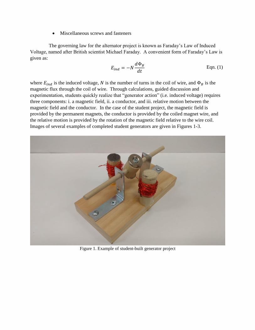
The governing law for the alternator project is known as Faraday’s Law of Induced
Voltage, named after British scientist Michael Faraday. A convenient form of Faraday’s Law is
given as:
𝐸𝑖𝑛𝑑 = −𝑁
𝑑Φ𝐵
𝑑𝑡 Eqn. (1)
where 𝐸𝑖𝑛𝑑 is the induced voltage, 𝑁 is the number of turns in the coil of wire, and Φ𝐵 is the
magnetic flux through the coil of wire. Through calculations, guided discussion and
experimentation, students quickly realize that “generator action” (i.e. induced voltage) requires
three components: i. a magnetic field, ii. a conductor, and iii. relative motion between the
magnetic field and the conductor. In the case of the student project, the magnetic field is
provided by the permanent magnets, the conductor is provided by the coiled magnet wire, and
the relative motion is provided by the rotation of the magnetic field relative to the wire coil.
Images of several examples of completed student generators are given in Figures 1-3.
Figure 1. Example of student-built generator project
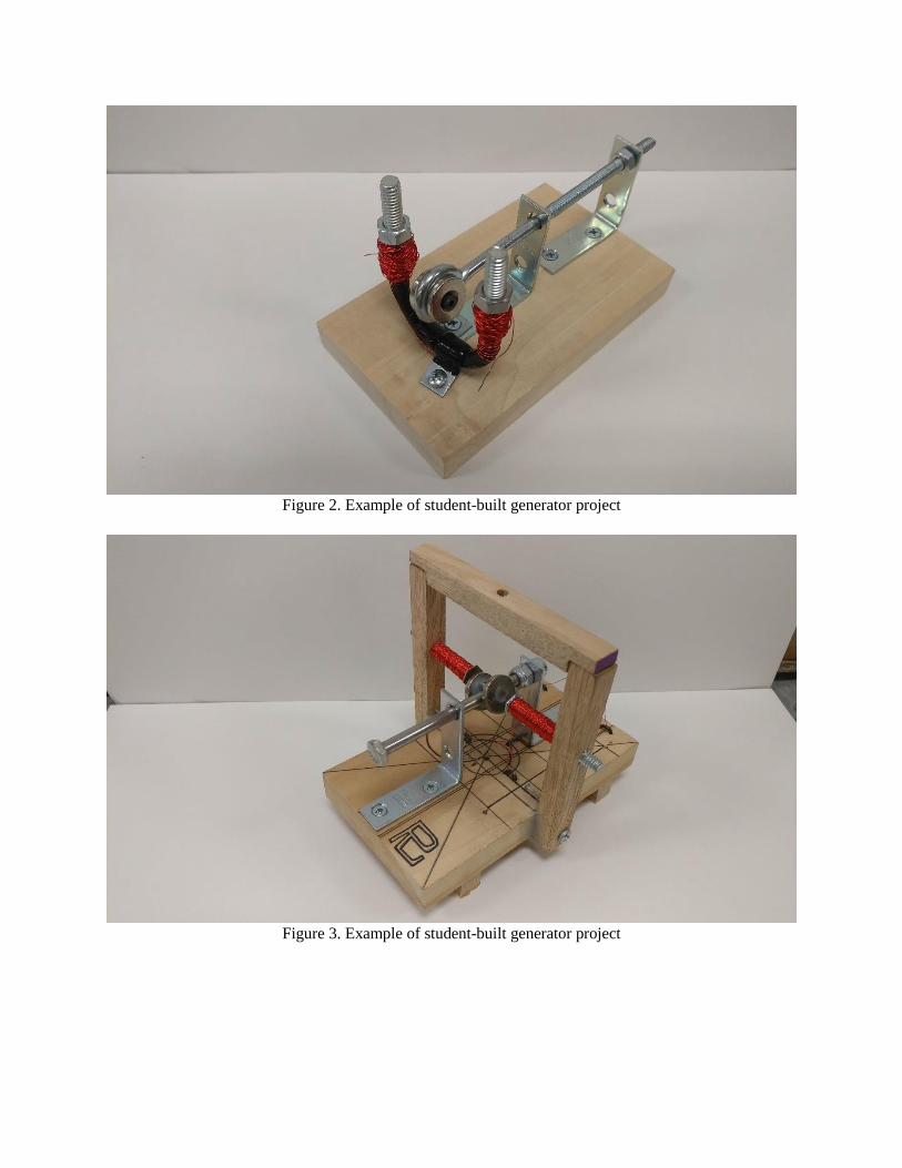
Figure 2. Example of student-built generator project
Figure 3. Example of student-built generator project
Testing and Assessment
Students are given approximately one month to design, construct and test their generator.
They are also warned that the project typically requires some trial-and-error, necessitating design
iteration. Testing of the generator is available throughout the one-month window, so students do
not have to wait until the due date to test their generators. Many of the students take heed of this
opportunity to iterate their design, and begin construction well in advance of the due date.
Students that take advantage of this opportunity to iterate their design usually end up with
higher-performing generators.
To test the generators, the students place their generators inside a plastic enclosure that is
approximately 4 feet x 4 feet x 4 feet. The enclosure is closed on all but one side. This is to
ensure that if the generators fly apart during testing (which happens occasionally), the flying
pieces will be contained by the plastic enclosure. Students connect the input shaft of their
generator to a corded electric drill, and the generator’s electrical output wires are connected to an
oscilloscope without any electrical load attached. The instructor monitors the oscilloscope and
calls out the measurements while the student operates the corded drill. The evaluated metric is
the peak open-circuit output voltage of the generator, measured from the horizontal axis to the
peak of the voltage waveform.
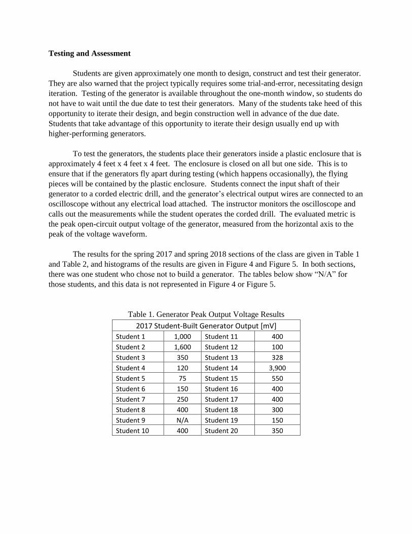
The results for the spring 2017 and spring 2018 sections of the class are given in Table 1
and Table 2, and histograms of the results are given in Figure 4 and Figure 5. In both sections,
there was one student who chose not to build a generator. The tables below show “N/A” for
those students, and this data is not represented in Figure 4 or Figure 5.
Table 1. Generator Peak Output Voltage Results
2017 Student-Built Generator Output [mV]
Student 1 1,000 Student 11 400
Student 2 1,600 Student 12 100
Student 3 350 Student 13 328
Student 4 120 Student 14 3,900
Student 5 75 Student 15 550
Student 6 150 Student 16 400
Student 7 250 Student 17 400
Student 8 400 Student 18 300
Student 9 N/A Student 19 150
Student 10 400 Student 20 350
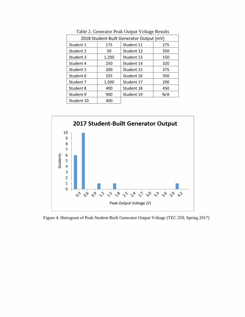
Table 2. Generator Peak Output Voltage Results
2018 Student-Built Generator Output [mV]
Student 1 175 Student 11 275
Student 2 50 Student 12 350
Student 3 1,200 Student 13 150
Student 4 250 Student 14 320
Student 5 300 Student 15 375
Student 6 325 Student 16 350
Student 7 1,500 Student 17 200
Student 8 400 Student 18 450
Student 9 900 Student 19 N/A
Student 10 400
Figure 4. Histogram of Peak Student-Built Generator Output Voltage (TEC 259, Spring 2017)
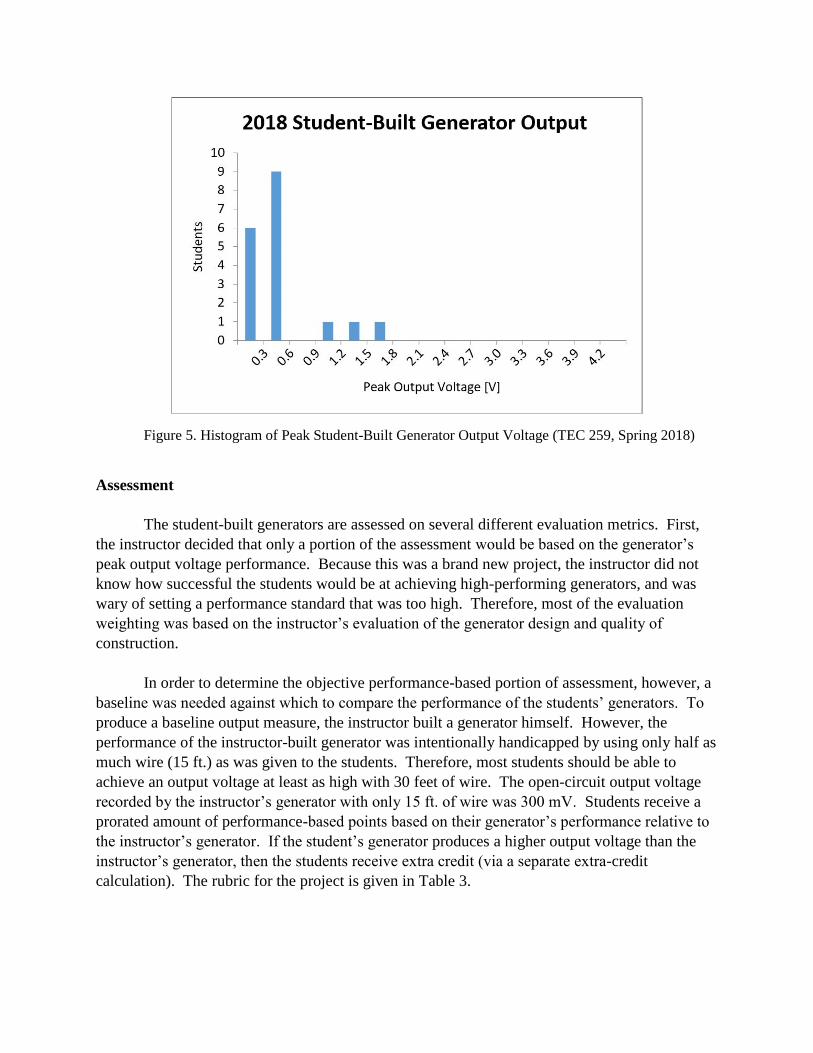
Figure 5. Histogram of Peak Student-Built Generator Output Voltage (TEC 259, Spring 2018)
Assessment
The student-built generators are assessed on several different evaluation metrics. First,
the instructor decided that only a portion of the assessment would be based on the generator’s
peak output voltage performance. Because this was a brand new project, the instructor did not
know how successful the students would be at achieving high-performing generators, and was
wary of setting a performance standard that was too high. Therefore, most of the evaluation
weighting was based on the instructor’s evaluation of the generator design and quality of
construction.
In order to determine the objective performance-based portion of assessment, however, a
baseline was needed against which to compare the performance of the students’ generators. To
produce a baseline output measure, the instructor built a generator himself. However, the
performance of the instructor-built generator was intentionally handicapped by using only half as
much wire (15 ft.) as was given to the students. Therefore, most students should be able to
achieve an output voltage at least as high with 30 feet of wire. The open-circuit output voltage
recorded by the instructor’s generator with only 15 ft. of wire was 300 mV. Students receive a
prorated amount of performance-based points based on their generator’s performance relative to
the instructor’s generator. If the student’s generator produces a higher output voltage than the
instructor’s generator, then the students receive extra credit (via a separate extra-credit
calculation). The rubric for the project is given in Table 3.
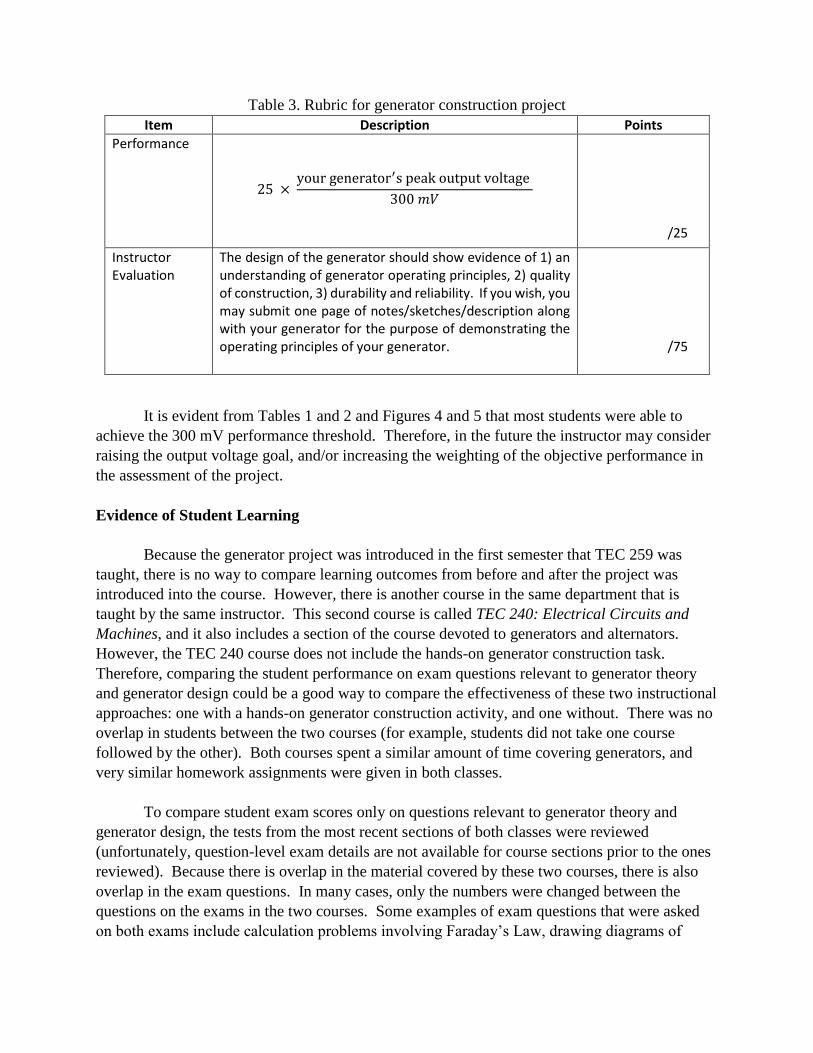
Table 3. Rubric for generator construction project
Item Description Points
Performance
25 × your generator′s peak output voltage
300 𝑚𝑉
/25
Instructor Evaluation
The design of the generator should show evidence of 1) an understanding of generator operating principles, 2) quality of construction, 3) durability and reliability. If you wish, you may submit one page of notes/sketches/description along with your generator for the purpose of demonstrating the operating principles of your generator.
/75
It is evident from Tables 1 and 2 and Figures 4 and 5 that most students were able to
achieve the 300 mV performance threshold. Therefore, in the future the instructor may consider
raising the output voltage goal, and/or increasing the weighting of the objective performance in
the assessment of the project.
Evidence of Student Learning
Because the generator project was introduced in the first semester that TEC 259 was
taught, there is no way to compare learning outcomes from before and after the project was
introduced into the course. However, there is another course in the same department that is
taught by the same instructor. This second course is called TEC 240: Electrical Circuits and
Machines, and it also includes a section of the course devoted to generators and alternators.
However, the TEC 240 course does not include the hands-on generator construction task.
Therefore, comparing the student performance on exam questions relevant to generator theory
and generator design could be a good way to compare the effectiveness of these two instructional
approaches: one with a hands-on generator construction activity, and one without. There was no
overlap in students between the two courses (for example, students did not take one course
followed by the other). Both courses spent a similar amount of time covering generators, and
very similar homework assignments were given in both classes.
To compare student exam scores only on questions relevant to generator theory and
generator design, the tests from the most recent sections of both classes were reviewed
(unfortunately, question-level exam details are not available for course sections prior to the ones
reviewed). Because there is overlap in the material covered by these two courses, there is also
overlap in the exam questions. In many cases, only the numbers were changed between the
questions on the exams in the two courses. Some examples of exam questions that were asked
on both exams include calculation problems involving Faraday’s Law, drawing diagrams of
magnetic fields, and applying Fleming’s “Right Hand Rule” for generator action. All questions
that were asked on the exams that were not directly related to generator principles were excluded
from further analysis. A summary of results is given in Table 4.
Table 4. Summary of generator-related exam question scores
Course n
(number of students) Number of generator-
related exam questions Score on generator-related
exam questions
TEC 240 (without generator construction activity)
22 7 71.8%
TEC 259 (with generator construction activity)
18 11 77.4%
As can be seen in Table 4, the score on generator-related exam questions was higher in
the course that included the generator construction activity. This is probably because the
students were consciously or even subconsciously thinking about generator operating principles
as they designed, built, tested, and iterated their generator. In order to meet the design objective
of the generator project, students were forced to make sense of Farday’s Law and apply it as they
constructed their own machine, rather than simply plugging numbers into the equation in
homework problems.
Conclusions and Students’ Lessons Learned
After discussion with the students following the project, most students seem to have
legitimately enjoyed the experience of building and testing their own generator. Some students
have kept their generators at the end of the semester as mementos of their accomplishments.
Some of the most salient instructor observations from the project include:
One of the first design decisions that students must make is whether to use the permanent
magnets provided to them, or a wound magnetic field instead. During the course the instructor
describes a multitude of different alternator and generator designs. Because of the inherent
simplicity of the permanent magnet generator design (and the fact that they are provided with
permanent magnets), all students thus far have chosen to build permanent magnet designs. The
second design choice that students must make is whether to place the magnetic field of the
machine on the rotor or the stator. Most students have chosen to place the permanent magnets on
the rotor and the armature windings on the stator. This eliminates the need for the students to
build slip rings. However, some students have successfully built designs with the armature
placed on the rotor using makeshift slip rings.
The concept of the “rate of change of magnetic flux” (given by the derivative in Eqn. (1)
is a difficult concept for many students to grasp. It is difficult for two reasons: first, the concept
of a derivative is not always firmly etched in all student’s minds. Second, magnetic flux itself is
difficult to envision, because it is not a tangible object. Putting these two concepts together,
therefore, is challenging for many students. To help students understand these concepts, the
instructor invests time in class discussions about what each of them mean.
If they have not already understood the 𝑑𝛷𝐵
𝑑𝑡 term in Eqn. (1) before they begin
constructing their generator, then the students quickly begin to understand the meaning of the
term once they begin experimenting with generator designs. Students quickly realize that the
generator output voltage increases proportionally to the speed of the generator’s rotor, which in
turn depends on the rotational speed of the drill. The output voltage increases as the rotor speed
increases because the rate of change of the magnetic flux through the generator coil(s) increases.
Also related to the derivative term in Eqn. (1) is the strength of the permanent magnets in
the generator design. Students are given two pairs of permanent magnets: a pair of two ceramic
magnets, and a pair of two neodymium magnets. Through experimentation, students learn that
the neodymium magnets produce a stronger magnetic field. As the stronger magnetic field
rotates on the rotor of the generator, the rate of change of magnetic flux through the wire coil is
greater, resulting in a higher peak output voltage than would be achieved by the same generator
design utilizing the ceramic magnets. In addition to the strength of the magnetic field, students
also find that in order to maximize the derivative term in Eqn. (1) that it is necessary to place the
rotating magnetic field as physically close as possible to the stationary coils of wire. This
requires careful construction of the machine so that the components do not interfere as the rotor
rotates. Because they are quite brittle, it is not uncommon for the neodymium magnets to break
in half if the stationary components of the alternator interfere with the rotating neodymium
magnets.
Students that begin their generator construction process early and are thus able to iterate
their design almost always eventually achieve higher output voltages than students who wait to
begin their construction until shortly before the due date. Although this is a self-evident truth for
most coursework, it is particularly true for this project because the concepts are challenging to
grasp. It is therefore rare for students to “get it just right” on their first construction attempt.
Another concept that students pick up on is the effect of adding more turns of wire to the
coil of their generator windings. As seen from Eqn. (1), the number of turns in the coil is
directly proportional to the output voltage. Because the length of wire given to the students is a
fixed length (30 feet), they soon realize that to increase the number turns in the coil, the coils
need to be tightly wound in a small diameter. This is one way that some of the students have
achieved output voltages greater than 1.0 Volts, as shown in Figures 4 and 5.
The generator construction project has proven to be a popular activity with students.
Students have repeatedly commented that the project was their favorite activity in the class.
From an instructor’s standpoint, it is rewarding to watch students engage in healthy competition
as they seek to build the highest-performing generator. In the two sections that the course has
been offered so far, six students (out of 39 enrolled in the courses) have achieved output voltages
greater than 1.0 volts. This is truly impressive performance, and required significant time and
dedication. In addition, the project has had a positive effect on exam performance related to
generator theory and design. This is shown by the increased scores on generator-related exam
questions for this course as compared to a similar course where a generator construction project
is not part of the course activities. It seems apparent that this project has engaged students and
enabled them to better understand the theory and operation of electric generators.
In future years, this project could be expanded to include several new factors. For
example, a cost could be assigned to each material that is provided. The objective for the
students could be to design the highest-performing generator possible with the lowest cost
achievable. Another possible extension is to measure the real-time power produced by the
generator over a given time interval, and then compare the energy produced by the generator
over the specified time interval. This could replace the current metric, which is the peak open-
circuit voltage. The energy produced by the generators will likely be very small, but it should be
able to be measured with data acquisition systems and Labview software. If the energy
consumed by the electric drill is also measured, then the conversion efficiency of the generator
could be calculated as well.
References
1. NEED Project, https://www.need.org/
2. KidWind Project, https://www.kidwind.org/
3. U.S. Department of Energy, Collegiate Wind Competition,
https://www.energy.gov/eere/collegiatewindcompetition/collegiate-wind-competition
4. Ma Wen Jie (Nov. 2018), Homemade Generator Science Project, Sciencing. Retrieved from
https://sciencing.com/homemade-generator-science-project-5340352.html
5. Wind Power: Creating a Wind Generator (Mar. 2011), Teacherstryscience. Retrieved from
http://www.teacherstryscience.org/lp/wind-power-creating-wind-generator
6. High School Student Develops $12 Generator (Apr. 2016), EC&M. Retrieved from
https://www.ecmweb.com/around-circuit/high-school-student-develops-12-generator
7. Marshall, J. (2003, June), Design And Fabrication Of A Low Voltage Direct Current Electric Motor
Paper presented at the 2003 Annual Conference, Nashville, Tennessee. https://peer.asee.org/12273
8. Mahreswaran, B. (2013, June), Impact of a Design Project on Engineering Physics: Motor does it
really motivated our students? Paper presented at 2013 ASEE Annual Conference & Exposition,
Atlanta, Georgia. https://peer.asee.org/19695
9. Wendell, D. (2017, June), Board # 151 : MAKER: Simple Motor for a Freshman Class Paper
presented at 2017 ASEE Annual Conference & Exposition, Columbus, Ohio.
https://peer.asee.org/27777
10. Williams, S. (2006, June), Brushless Dc Motor Project In An Introduction To Electrical Engineering
Course. Paper presented at 2006 Annual Conference & Exposition, Chicago, Illinois.
https://peer.asee.org/655
11. Clayton, G.M., & Stein, R. A. (2011, June), An Inexpensive Hands-on Introduction to Permanent
Magnet Direct Current Motors. Paper presented at 2011 ASEE Annual Conference & Exposition,
Vancouver, BC. https://peer.asee.org/17458