Embed Size (px)
Citation preview
The International Journal Of Engineering And Science (IJES)
|| Volume || 4 || Issue || 5 || Pages || PP.22-31 || 2015 ||
ISSN (e): 2319 – 1813 ISSN (p): 2319 – 1805
www.theijes.com The IJES Page 22
Improvement in Power Transmission Capacity by Simultaneous
AC-DC Transmission
1, Bhagyashri G. Sherkhane,
2, M. R. Bachawad
1, Department of Electrical Engineering,
Government College of Engineering, Aurangabad (M.S.), India. 2,
Department of Electrical Engineering
Government College of Engineering, Aurangabad (M.S.), India
---------------------------------------------------------------ABSTRACT-------------------------------------------------------
Now days in power transmission systems mainly the high voltage three phase AC or HVDC transmission
lines for greater efficiency at very long distances are used. In this paper, we have to show the scheme of AC and
DC power transmission system which can be developed by converting double circuit ac line into composite AC
and DC power transmission line and also comparing simulation results with the simple EHVAC transmission
system and HVDC transmission system having six pulses PWM generator. The main object of thesis is to show
that by superimposing DC in AC transmission, the capacity of the transmission line can be increased by nearly
70 % of that if only AC is transmitted. In our existing transmission system, long extra high voltage (EHV) AC
lines cannot be loaded to their thermal limits in order to keep sufficient margin against transient instability. With
the scheme proposed in this project, it is possible to load these lines close to their thermal limits. The conductors
are allowed to carry usual ac along with dc superimposed on it, without altering the original line conductors,
tower structures, and insulator strings has been presented.
KEYWORDS: AC and DC power transmission, flexible AC transmission system (FACTS), MATLAB
simulation, six pulses PWM generator, Simultaneous AC-DC transmission.
------------------------------------------------------------------------------------------------------------ ----------------------------
Date of Submission: 27-April-2015 Date of Accepted: 10-May-2015
------------------------------------------------------------------------------------------------------------ ----------------------------
I. INTRODUCTION Electric power transmission is nothing but the bulk transfer of electrical energy, from generating power
plants to electrical substations which are located near demand center. The transmission lines, when
interconnected with each other forms transmission network. To design a transmission networks for transferring
the electrical power with high efficiency, some factors are taken into account such as economic factors, network
safety and redundancy.
In recent years, the demand of electrical power has uneven growth therefore to transfer such a power for
long distance with high efficiency the new transmission lines are constructed. The availability of power is
generally at remote location which is not close to growing load centers. These locations are determined by
environmental acceptability, regulatory policies and cost of available energy. To transfer a high electric power
through existing long AC lines to load centers has certain limitations due to stability considerations. Thus, these
lines are not loaded to their thermal limits to keep sufficient margin against transient stability [1]-[4]. To fulfill
the present situation demands the new concepts that allow full utilization of transmission facilities without
decreasing system availability and security. The new power electronic technology of flexible AC transmission
(FACTS) devices is used in existing AC transmission system to improve stability and achieve power
transmission to its thermal limit.
II. LITERATURE SURVEY In this paper the improvement of power transmission capacity by simultaneous AC-DC transmission is
shown. The flexible AC transmission system (FACTS) concepts, based on applying state-of-the-art electronic
technology to existing AC transmission system, improve stability and which also gives power transmission close
to its thermal limit [1]-[4]. A high voltage direct current (HVDC), electric power transmission system uses direct
current for bulk electric power transmission. For long distance transmission the HVDC system has less
expensive and having lower electrical losses. In this paper the feasibility study of conversion of double circuit
AC line into composite AC-DC line can be done in which DC link having the high voltage DC transmission line
Improvement in Power Transmission Capacity by Simultaneous AC-DC Transmission
www.theijes.com The IJES Page 23
which is having certain advantages like environmental, economic, asynchronous connections and power flow
control, etc. [5]. The development of DC transmission since in 1950 and which plays a major role in extra-long
distance transmission with supplementing EHVAC transmission system. These transmission scheme having the
capability to improve the power transferring capacity i.e. power upgrading of a transmission line.
III. SIMULTANEOUS AC–DC POWER TRANSMISSION
3.1 Scheme for Simultaneous Ac-Dc Transmission:
Fig. 1 shows the power transmission by using both AC & DC power flow. The simultaneous power
flow in AC-DC can be obtained by converting a double circuit AC line into composite AC-DC. This composite
AC-DC line carries both three-phase AC as well as DC power. The each line conductor must carry one third of
total DC current along with the AC current flow in the circuit. From the circuit the DC power is obtained through
the line commutated 12-pulse Rectifier Bridge & that can be given to the neutral point of sending end zigzag
transformers secondary. Again the DC power can be converted into AC by conventional line commutated 12-
phase bridge inverter at receiving end zigzag transformers secondary. Here, the inverter bridge is also connected
to neutral of receiving end transformer of zigzag connected winding. For the DC current is equally divided
among all the three phase of transmission line, the resistance is also maintain equal in all the three phases of
secondary winding of zigzag transformer as well as in three conductors of the transmission line.
At the time of DC power flow the transformer may be saturated due to DC current, to avoid the
saturation the zigzag connected winding is used at both ends. Also, the three conductors at second line provide
the return path for dc current. The harmonics in DC current can be reduced using a high value of reactor ‘Xd’.
Under normal operating conditions if the absence of zero sequence and third harmonics or it multiple harmonic
voltages, the AC current flow through each transmission line can be restricted between the zigzag connected
windings & three conductors of the transmission line. Due to high voltage of ‘Xd’, even the presence of all these
components of voltages able to produce negligible current through the ground. The two fluxes produced by the
dc current (Id/3) flowing through each limb of core of zigzag transformer winding are equal in magnitude but
opposite in direction. So the net dc flux becomes zero at any instant of time in each limb of the core. Thus, in
each limb of core the dc saturation is avoided.
Fig. 2 shows the equivalent circuit of the scheme under normal steady-state operating condition that
assumes current control of rectifier and extinction angle control of invertor are constant. The path for AC return
current can be denoted by the dotted lines. In the figure, the second transmission line carries return DC current
and each line conductor carries (Id/3) along with AC current per phase. The ‘Vdro’ and ‘Vdio’ are the maximum
values of rectifier and inverter side DC voltage respectively and which are equal to 3√2 time’s converter AC
input line-to- line voltages. The R, L and C are the resistance, inductance and capacitance of the line parameters
per phase of each line. The ‘α’ and ‘Ɣ’ are the firing and extinction angles of rectifier and inverters, respectively
[4], [6]-[8]. Also ‘Rcr’ and ‘Rci’ are the commutating resistance.
The expressions for AC voltage and current and for active and reactive powers in terms of A,B,C and D
parameters of each line can be written by neglecting resistive drops in line conductors and transformer windings
due to DC current. Therefore, A , B, C and D parameters of each line may be written as:
ES = AER + B
(1)
IS = CER + DIR
(2)
PS + j QS = – ES / B
* + [D
*
/ B*]
(3)
PR + j QR = ER / B
* - [A
*
/ B*]
(4)

Improvement in Power Transmission Capacity by Simultaneous AC-DC Transmission
www.theijes.com The IJES Page 24
Fig. 3.1 Scheme for composite ac–dc transmission
Fig. 3.2 Equivalent Circuit
IV. CASE STUDY
4.1 Mathematical Calculations:
A synchronous machine is feeding power to infinite bus via a double circuit, with the following
specifications. The synchronous machine is dynamically modeled, a field coil on d-axis and a damper coil on q-
axis, by Park’s equations with the frame of reference based in rotor. It is equipped with an IEEE type AC4A
excitation system. Transmission lines are represented as the Bergeron model. It is based on a Distributed LC
parameter travelling wave line model, with lumped résistance. Its represents the L and C elements of PI section
in a distributed manner.
The feasibility of the conversion of the AC Line to Composite AC-DC Line are considered.
Consider data:
Synchronous Machine:
Power = 550 MVA, Voltage = 24KV, Frequency = 50Hz
Transmission line Parameters:
Phase = 3-Φ, Voltage = 400KV, Length (l) =450Km
Z=0.03252 + j0.33086 Ω/Km/ph/ckt
(3.1)
Y =j03.33797×10-6
S/Km/ph/ckt
(3.2) Thermal limit, Ith=1.8KA/ckt
(3.3)
X=74.4435 Ω/ph
(3.4)
Sending End Voltage (Rms) =
(3.5)
Improvement in Power Transmission Capacity by Simultaneous AC-DC Transmission
www.theijes.com The IJES Page 25
Sending End Current,
Surge impedance,
(3.6)
Substituting the Z and Y from equations (3.1) & (3.2) in the equation (3.6), we get
Consider,
(3.7)
3.2 Determination of ABCD parameters:
A, B, C and D parameters (see appendix-I) of each line are computed as follows:
A=Cosh γl
=Cosh(0.023237+j0.47343)
=Cosh(0.023237)Cos(0.47343) + Sinh(0.023237)Sin(0.47343)
=0.999+j1.918 10-4
A=0.999∟0.0109
B=ZcSinhγl
=315.59∟-2.81 [Sinh(0.023237+j0.47343)]
=315.59∟-2.81 [Sinh(0.023237)cos(0.47343)+jCosh(0.023237)sin(0.47343)]
B=7.778∟16.776
=
C =7.804 ∟22.39
We know that. A=D=0.999∟0.0109
Sending end voltage and current are written as:
ES=A.ER+B.IR & IS=C.ER+D.IR
Therefore the SE and RE Voltage and Currents are calculated:
ES=230.94∟0 KV & IS=0.793∟0 KA
ER=224.7∟-0.445 KV & IR=0.8125∟0.58 KA
Active and Reactive Power in terms of ABCD parameters are:
= (189.7363+J3.021)
Ps+jQs = 189.76 0.91 M.W
= (-185.2085+j1.51)
PR+JQR = 185.209∟179.84 MW
Improvement in Power Transmission Capacity by Simultaneous AC-DC Transmission
www.theijes.com The IJES Page 26
Therefore the Active and reactive powers of SE & RE are given as:
Ps+jQs = 189.76∟0.91 M.W
PR+JQR = 185.209∟179.84 MW
Let,
Vph = per phase rms voltage of original AC line,
Va = per phase rms voltage of composite AC-DC line,
Vd = DC voltage superimposed on Vph
Allowing maximum permissible voltage offset such that the composite voltage wave just touches zero in every
cycle:
Vd = Vph/√2
Substituting equation (3.5), in the above equation:
Vd=163.299 KV
And the rms value of voltage of composite AC-DC line is given by_
Va = Vph/2
Va = 115.47 KV
We know that reactance per phase of double circuit line is X=74.4435Ω/ph. Let δ1 is the power angle
between the voltage at the two ends (to keep sufficient stability margin.δ1 is generally kept low for long lines
and seldom exceeds 30 ْ ). And δ2 is the power angle between the AC voltages at the two ends of the composite
line.
Total power transferred through the double circuit line before conversion is as follows:
But AC current/ph/ckt of double circuit line may be computed as
Therefore, Total power transfer through the composite line is
.
Consider the Power Angle, ْ ْ , Then, P’total = Pac,
Substituting equation (3.4) & (3.5)
Pac = 1074.6394MW
AC current/ph/ckt.
Ia= 0.7755 KA
But the dc current,
Id = 4.873 KA
Total power transferred through the composite line is:
Pac+dc = 1860.16 MW
4.2 Conclusions:
Hence we can conclude from the above equations that, the Power through only the AC circuit is
calculated as the Pac=1074.639MW.When we superimposed the DC current of Id=4.873KA over the AC power
by maintaining thermal limit, it is observed that the power is improved to the Pac+dc=1860.16. This shows that the
load ability of transmission lines are increased by adding DC to the AC in the long transmission lines by
maintaining the system stability and thermal limit.
Improvement in Power Transmission Capacity by Simultaneous AC-DC Transmission
www.theijes.com The IJES Page 27
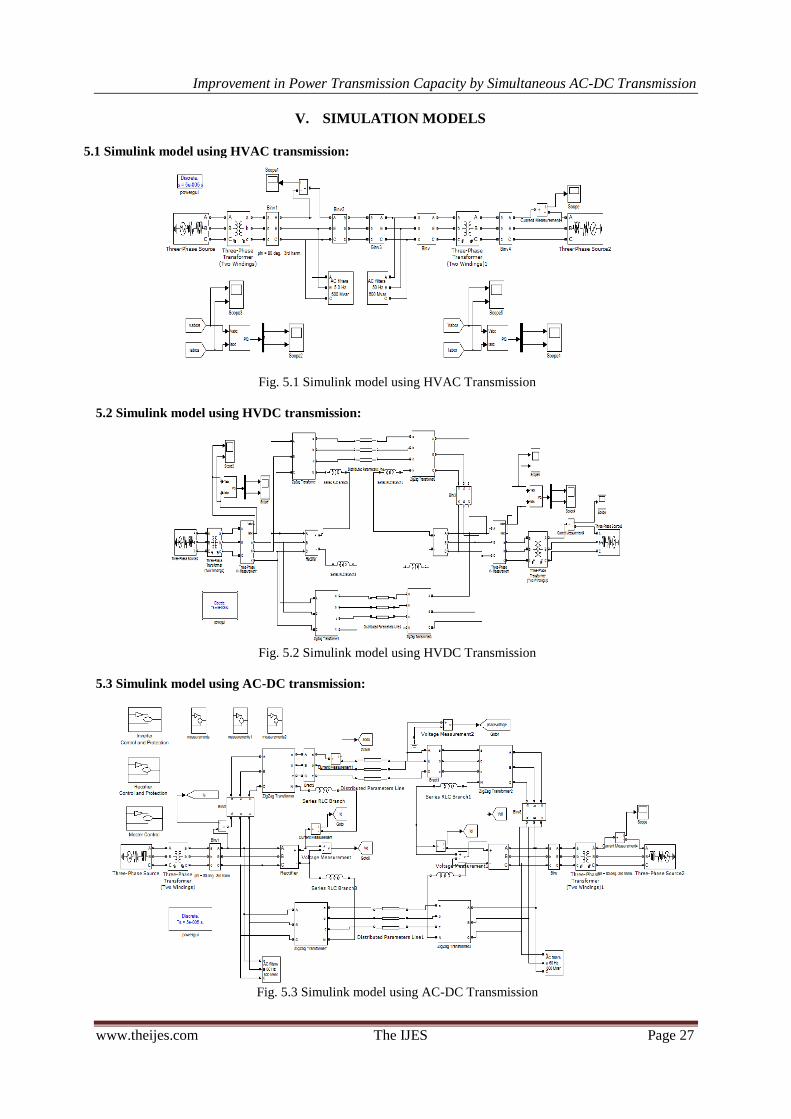
V. SIMULATION MODELS
5.1 Simulink model using HVAC transmission:
Fig. 5.1 Simulink model using HVAC Transmission
5.2 Simulink model using HVDC transmission:
Fig. 5.2 Simulink model using HVDC Transmission
5.3 Simulink model using AC-DC transmission:
Fig. 5.3 Simulink model using AC-DC Transmission
Improvement in Power Transmission Capacity by Simultaneous AC-DC Transmission
www.theijes.com The IJES Page 28
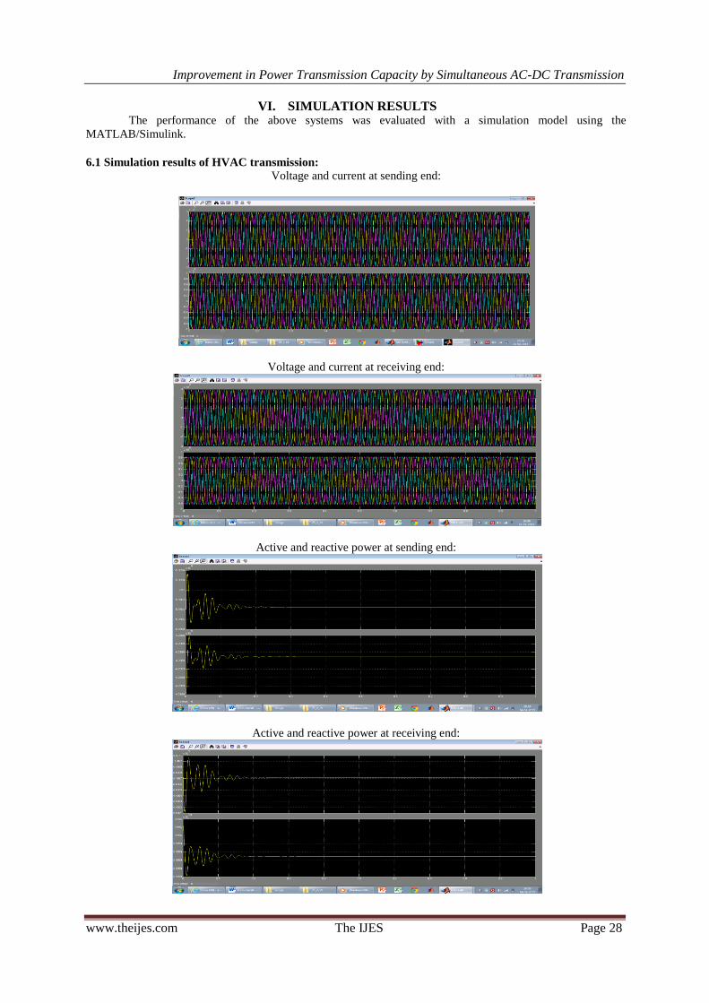
VI. SIMULATION RESULTS The performance of the above systems was evaluated with a simulation model using the
MATLAB/Simulink.
6.1 Simulation results of HVAC transmission:
Voltage and current at sending end:
Voltage and current at receiving end:
Active and reactive power at sending end:
Active and reactive power at receiving end:
Improvement in Power Transmission Capacity by Simultaneous AC-DC Transmission
www.theijes.com The IJES Page 29
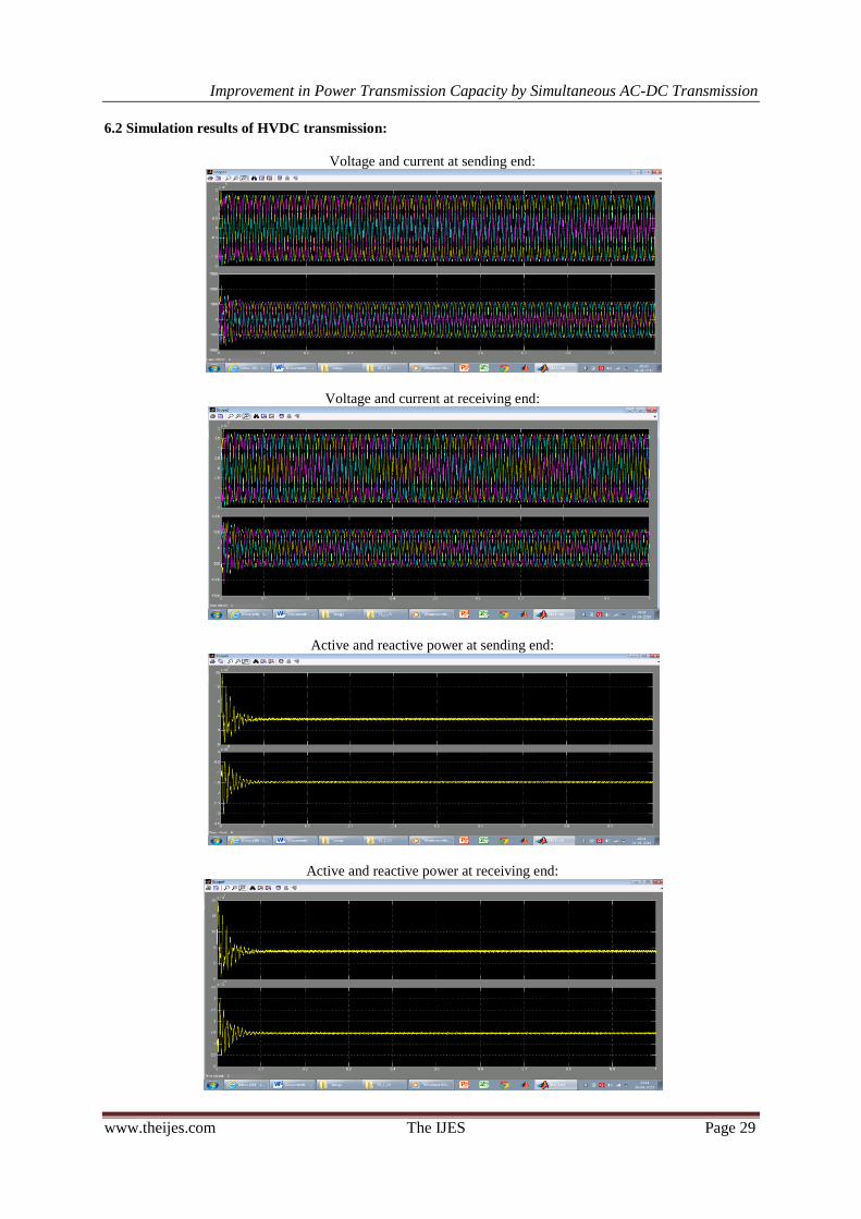
6.2 Simulation results of HVDC transmission:
Voltage and current at sending end:
Voltage and current at receiving end:
Active and reactive power at sending end:
Active and reactive power at receiving end:

Improvement in Power Transmission Capacity by Simultaneous AC-DC Transmission
www.theijes.com The IJES Page 30
6.3 Simulation results of using AC-DC transmission:
Combined AC DC current and AC current in zigzag transformer:
Rectifier AC voltage and current:
Sending end voltage:
Receiving end voltage:
Improvement in Power Transmission Capacity by Simultaneous AC-DC Transmission
www.theijes.com The IJES Page 31
VII. CONCLUSION The power transmission capacity of a transmission line can be improved by using the simultaneous AC-
DC transmission system has been demonstrated. This transmission capacity of the transmission line can be
increased by nearly 70% of that if AC is transmitted. For the simultaneous AC-DC transmission system studied,
which increase the load ability of line up to 83% and also the line loaded to its thermal limit with superimposed
DC current. The DC power superimposing in AC transmission does not create in stability problem i.e. does
affect the transient stability. In this scheme the DC current regulator modulate the AC power flow without
altering the size of conductor, insulator string and tower structure of the original transmission line. The
respective Simulink models of HVAC and HVDC transmission systems shows the power transfer ratings which
are having the low values than in simultaneous AC-DC transmission system.
VIII. FUTURE SCOPE In this paper, it is shown that superimposing the DC in AC transmission improves power transmission
capacity of transmission line nearly 70% of only AC transmitted (i.e. by 2 to 4 times) without altering any
physical equipment. In every transmission line the faults are occurred which interrupts the power supply, to
avoid the faulty conditions some protection schemes are used in transmission line. By considering such a
drawback in transmission line and with using a solution technique this work can be extended for analyzing the
faults effect and different protect schemes suitable to that particular type of transmission.
REFERENCES [1] L. K. Gyugyi, “Unified power flow concept for flexible A.C. transmission system,” Proc. Inst. Elect. Eng., p. 323, Jul. 1992.
[2] L. K. Gyugyi et al., “The unified power flow controller; a new approach to power transmission control,” IEEE Trans. Power
Del., vol. 10, no. 2, pp. 1085–1097, Apr. 1995. [3] N. G. Hingorani, “FACTS—flexible A.C. transmission system,” in Proc. Inst. Elect. Eng. 5th. Int. Conf. A.C. D.C. Power
Transmission, London, U.K., 1991.
[4] P. S. Kundur, Power System Stability and Control. New York: Mc-Graw-Hill, 1994. [5] A. Clerici, L. Paris, and P. Danfors, “HVDC conversion of HVAC line to provide substantial power upgrading,” IEEE Trans.
Power Del., vol. 6, no. 1, pp. 324–333, Jan. 1991.
[6] Padiyar, HVDC Power Transmission System. New Delhi, India: Wiley Eastern, 1993. [7] E. W. Kimbark, Direct Current Transmission. New York: Wiley, 1971, vol. I.
[8] J. Arillaga and N. R.Watson, Computer Modelling of Electrical Power Systems. Chichester, U.K.: Wiley, 2003.
[9] K. P. Basu and B. H. Khan, “Simultaneous ac-dc power transmission,” Inst. Eng. (India) J.-EL, vol. 82, pp. 32–35, Jun. 2001. [10] H. Rahman and B. H. Khan, “Enhanced power transfer by simultaneous transmission of AC-DC: a new FACTS concept,” in
Proc. Inst. Elect. Eng. Conf. Power Electronics, Machines, Drives, Edinburgh, U.K., Mar. 31–Apr. 2 2004, vol. 1, pp. 186–191.
[11] M. A. Chaudhry and D. P. Caroll, “Coordinated active and reactive power modulation of multiterminal HVDC system,” IEEE Trans. Power App. Syst., vol. PAS-103, pp. 1480–1485, 1989.
[12] K. R. Padiyar, M. A. Pai, and C. Radhakrishna, “Analysis of D.C. link control for system stabilization,” in Proc. Inst. Elect.
Eng. Conf. Publ.No. 205, London, U.K., 1981, pp. 145–148. [13] M. Stella, P. K. Dash, and K. P. Basu, “A neuro-sliding mode controller for STATCOM,” Elect. Power Compon. Syst., vol. 32,
pp. 131–147, Feb. 2004.
[14] M. Szechtman, T. Wees, and C. V. Thio, “First benchmark model for HVDC control studies,” Electra, no. 135, pp. 54–67, Apr. 1991.