Embed Size (px)
Citation preview

Department of Automatic Control
Implementation of Service Orchestrated control procedures
in OPC UA for JGrafchart
Johan Hagsund

MSc Thesis ISRN LUTFD2/TFRT--5953--SE ISSN 0280-5316
Department of Automatic Control Lund University Box 118 SE-221 00 LUND Sweden
© 2014 by Johan Hagsund. All rights reserved. Printed in Sweden by Media-Tryck Lund 2014

Abstract
The automation industry is facing many challenges with higher demands on theirproduction process. Technology used today does not allow for fast changes in theproduction line. This thesis will investigate how services can be modelled using anew standard OPC UA for data exchange. Encapsulation of the mechatronic func-tions as services will allow for creating control software using a SOA approach. Anexperimental set-up will investigate how an OPC UA server and client are created.
1


Acknowledgements
This master thesis has been carried out as a cooperation between the Smart Fac-tory in Kaiserslautern, Germany, and the department of automatic control at LundUniversity. It has given me the opportunity to work in the front of very importantresearch topic.
I would like to thank Moritz Ohmer and Lisa Ollinger from the Smart Factoryfor guiding me in my work in Kaiserslautern and for baring with me when theGerman skills were not enough. I would also like to thank Benjamin Kiepke forassiting me with all kinds of questions that came up during the project while still inGermany.
I would also like to thank Alfred Theorin from the department of automatic con-trol for all the input via our Skype meetings and for all the support with JGrafchart,the analysis of the results and discussions about the report.
3

Acronyms
DFKI Deutsches Forschungsentrum für Künstliche Intelligenz
DOS Disk Operating System
DPWS Devices Profile for Web Services
HMI Human Machine Interface
OPC AE OPC Alarm and Events
OPC DA OPC Data Access
OPC HDA OPC Historical Data Access
OPC UA OPC Unified Architecture
PLC Programmable Logical Controller
SCADA Supervisory Control And Data Acquisition
SDK Software Development Kit
SOA Service Oriented Architecture
SOA-AT Service Oriented Architecture in Automation Technologies
URI Uniform Resource Identifier
WSDL Web Service Description Language
5

Contents
1. Introduction 91.1 Introduction . . . . . . . . . . . . . . . . . . . . . . . . . . . . 91.2 Smart Factory . . . . . . . . . . . . . . . . . . . . . . . . . . . 91.3 Methodology . . . . . . . . . . . . . . . . . . . . . . . . . . . . 101.4 Outline . . . . . . . . . . . . . . . . . . . . . . . . . . . . . . . 10
2. Background 112.1 Background . . . . . . . . . . . . . . . . . . . . . . . . . . . . 11
3. Theory 133.1 Introduction . . . . . . . . . . . . . . . . . . . . . . . . . . . . 133.2 Service Oriented Architecture . . . . . . . . . . . . . . . . . . . 133.3 Service Oriented Architecture in Automation Technologies (SOA-
AT) . . . . . . . . . . . . . . . . . . . . . . . . . . . . . . . . . 143.4 Devices Profile for Web Services . . . . . . . . . . . . . . . . . 143.5 OPC Unified Architecture . . . . . . . . . . . . . . . . . . . . . 153.6 Grafchart . . . . . . . . . . . . . . . . . . . . . . . . . . . . . . 18
4. Problem description 224.1 Problem description . . . . . . . . . . . . . . . . . . . . . . . . 22
5. OPC UA 235.1 Address space model . . . . . . . . . . . . . . . . . . . . . . . 235.2 Information modelling . . . . . . . . . . . . . . . . . . . . . . . 245.3 Building blocks . . . . . . . . . . . . . . . . . . . . . . . . . . 245.4 ObjectTypes vs Objects . . . . . . . . . . . . . . . . . . . . . . 25
6. Tools 286.1 Introduction . . . . . . . . . . . . . . . . . . . . . . . . . . . . 286.2 Unified Automation UaModeler . . . . . . . . . . . . . . . . . . 286.3 Prosys OPC UA Java SDK Client . . . . . . . . . . . . . . . . . 296.4 Softing OPC UA C++ Server Development Toolkit for Linux . . 29
7. Service modelling in OPC UA 317.1 Introduction . . . . . . . . . . . . . . . . . . . . . . . . . . . . 31
7
Contents
7.2 Generic OPC UA device . . . . . . . . . . . . . . . . . . . . . . 317.3 Services modelled in OPC UA . . . . . . . . . . . . . . . . . . 327.4 Service library . . . . . . . . . . . . . . . . . . . . . . . . . . . 35
8. Client and Server implementation together with JGrafchart 388.1 Introduction . . . . . . . . . . . . . . . . . . . . . . . . . . . . 388.2 Fischertechnik device . . . . . . . . . . . . . . . . . . . . . . . 388.3 Server . . . . . . . . . . . . . . . . . . . . . . . . . . . . . . . 388.4 Modelling a sensor on the server . . . . . . . . . . . . . . . . . 418.5 Client . . . . . . . . . . . . . . . . . . . . . . . . . . . . . . . . 41
9. Results 489.1 Result from service modelling . . . . . . . . . . . . . . . . . . . 489.2 Result from implementation . . . . . . . . . . . . . . . . . . . . 48
10. Discussion 4911. Future work 50Bibliography 51
8
1Introduction
1.1 Introduction
The requirements on modern automation applications are changing, the control sys-tems are getting more and more advanced. At the same time the control systemsneeds to be developed faster, reducing the set-up time an the time it takes for modi-fications. Companies are expanding all over the world setting up production cells inmultiple countries. Together with an increased threat level for industrial espionagethis calls for automation systems with high security features that can connect plantsall around the world. This thesis will not provide the solution to all these issues,it will focus on how services can be modelled in OPC Unified Architecture (OPCUA), a new standard for data exchange and information integration, and also to im-plement a control software in JGrafchart for a device from Firschertechnik usingOPC UA for communications.
The first section will focus on how services can be modelled in OPC UA.The second part will focus on how OPC UA has been implemented together withJGrafchart for controlling the device from Fischertechnik. During the time of thisproject twelve weeks have been spent in Kaiserslautern at the SmartFactory atDFKI, the German Institute for Artificial Knowledge, to learn about OPC UA andto program the implementation of OPC UA. The second part has been spent in Lundfor analysis and conclusions of the work.
1.2 Smart Factory
"...the intelligent factory of the future" [SmartFactoryKL]
The SmartFactory is a manufacturer-independent research and demonstration plantestablished with the goal to transfer new smart technologies into the industrial envi-ronment. SmartFactory works in close collaboration with multiple companies to putnew ideas into practise in joint projects, the SmartFactory works in the area betweenresearch and industry [SmartFactoryKL].
9

Chapter 1. Introduction
1.3 Methodology
This project will be structured in two parts where the first part has a more theoreticalfocus and where the second part focus on implementation. In Kaiserslautern the firstweeks was mainly spent on studying OPC UA in order to understand the conceptof it as well as getting familiar to other technologies used in the industry today.Once the basic theory was understood the programming started for creating an OPCUA client and server that could be used for the project. A lot of the programmingwas done in Kaiserslautern since they were more familiar with OPC UA already.OPC UA theory was studied in parallel throughout the entire course of the projectsince there is always more to be learned. During the last weeks in Germany focuswas to create a working set-up where an application in JGrafchart could control asimulated device on the server. Once back in Lund the analysis of the results startedas well as the creation of the report.
1.4 Outline
This outline presents an overview of the different parts in this thesis. The thesis isdivided into two parts where the first part studies OPC UA and investigates howservices, in theory, can be modelled in OPC UA. In the second part a working setup with an OPC UA server and client is to be created.
Chapter 1 contains a short introduction and presents the outline of the project.Chapter 2 presents the background of this thesis describing the trends in the indus-try today.Chapter 3 goes through the different theories and technologies used during theproject such as SOA, DPWS, OPC-UA and Grafchart.Chapter 4 present the problem description for this thesis.Chapter 5 discusses OPC UA in more detail and describes the available buildingblocks.Chapter 6 gives a short introductions to the different tools used during the process.Chapter 7 presents different ways services and be modelled in OPC UA.Chapter 8 is where the second part of the thesis starts with the creation of an OPCUA server and client as well as describing the physical device from Fischertechnikused during the project.Chapter 9 goes through the results from the project.Chapter 10 discusses the results and the conclusions are presented.Chapter 11 is the final chapter containing suggestions for future work.
10
2Background
2.1 Background
There is a trend in the manufacturing industry today towards shorter product lifecycles, an increased customer demand of individualized goods and a more complexproduction. In order to meet these demands from more complex production pro-cesses the requirements on the automation systems are increasing. A higher degreeof reusability must be achieved in order to manage the demands for shorter set-uptimes [Ollinger et al., 2011] [Ollinger and Zühlke, 2013]. In order for the companiesto stay successful they need to be able to adapt and reconfigure their production linesquickly to match the changing demands. The increase complexity in the automationsystems calls for a more advanced control system to handle it.
The classic way for controlling such production processes is the use of pro-grammable logical controllers (PLC). Programming of such controllers is done at avery low level and in the very last step of the implementation. There are no tools forcombining the information from the planning stage into the implementation on thePLC. The code is very dependent on the hardware and needs to be developed fromthe beginning for each new project [Ollinger and Zühlke, 2013].
The modern manufacturing industry can not allow for such time consumingengineering processes of developing new code for each new project due to the de-mands for fast reconfiguration of the production process. The limited possibility ofintegrating the different stages in the development and planning of a new produc-tion line together with the inability to reuse already created code calls for a newtechnology [Theorin and Johnsson, 2012] [Theorin et al., 2013]. It is estimated thatthe cost for set-up and installations sums up to almost one third of the total costduring the life time of a plant [Jammes et al., 2005]. Replacing broken parts withnew also makes up for a substantial part of the cost. It could be that the exact samepart is no longer available and with a hardware specific control system this requiresa substantial engineering effort only for a small replacement of a part.
There is a new concept that has shown some success in this field of improvingthe level of reusability of control systems as well as making the production processmore flexible and it is called Service Oriented Architecture (SOA). SOA has the
11
Chapter 2. Background
potential to solve many of the issues the industry is facing. It is a new technologyfor the automation world, an industry that is known for its slow acceptance fornew technologies [Theorin and Johnsson, 2012], that need more testing but somestudies has shown promising results [Bohn et al., 2006]. Investigating how servicescan be modelled in OPC UA can be one step in convincing the industry to use thisapproach. Integrating it into JGrafchart for service orchestration to create controlsoftware together with creating a real application showing the results could opentheir eye for this new way for controlling a plant.
12
3Theory
3.1 Introduction
This chapter will go through the main technologies used during this project suchas SOA, SOA-AT, DPWS and OPC UA. SOA is a software concept where specificfunctionality is made available as services to others. SOA-AT deals with how SOAcan be implemented in the automation industry so these two makes up the base onhow services can be described. DPWS is a technology that implements SOA-ATand is in this project studied in order to make a comparison with how is could bedone in OPC-UA which is the last technology. In the end of this chapter Grafchartis described which is used in the second part this thesis for the implementation inJGrafchart.
3.2 Service Oriented Architecture
Service oriented architecture (SOA) is not a technology or standard by it self[Ollinger et al., 2011], it is a concept for high-level software architecture. The basicprinciple of SOA is that the software is broken down to smaller discrete pieces ofcode that each describes a small part of the applications functionality. This func-tionality is modelled and made available to other parts of the application in formof a service. Breaking down large projects into smaller pieces in form of servicesis called service orientation [Wikipedia, 2014]. Each service contains some metadata describing the functionality it is encapsulating. To create applications usingthe SOA concept multiple services are combined and used together which is calledservice orchestration [Theorin, 2013].
Encapsulation of the functionality of the field devices in form of services raisesthe abstraction level of the application programming allowing for the same servicesto be used in another application using similar devices. This means a higher de-gree of reusability, reduced development times [Wikipedia, 2014] as well as a moreflexible production [Theorin, 2013].
13
Chapter 3. Theory
3.3 Service Oriented Architecture in AutomationTechnologies (SOA-AT)
Applying the concept of SOA within industrial automation has the potential to solvemany of the issues the industry is facing with an increased demands on flexibilityand shorter set-up times [Theorin et al., 2013]. SOA is originally developed to beused for business processes but the idea of breaking down the process into smallerpieces can be applied in the automation industry as well and is then called Ser-vice Oriented Architecture in Automation Technologies (SOA-AT). The differencewhen applying the SOA paradigm in the automation industry compared to a reg-ular business processes is that the place where the services are executed matters.Instead of executing the services on a large computer as in a regular business pro-cesses they are now executed on small embedded devices with limited resourcesconnected with the different field devices [Theorin, 2013]. The physical functional-ity of the field devices such as actuators and sensors is modelled as basic servicesthat connect the automation systems with the real processes [Theorin et al., 2013].These basic services are sometimes referred to as mechatronic functions since theyhave a direct contact with the process [Ollinger and Zühlke, 2013], they representthe actual actions of the real machinery. Multiple basic services can be modelledtogether and form a composed service. This is done to raise the level of abstractionof the written control application. The control software is created by orchestratingmultiple services together [Theorin, 2013]. Each service has a number of operationsthat can be executed for accessing the functionality of the device.
The use of SOA-AT has not spread so much yet, the industrial automation in-dustry is rather slow on adapting new techniques and prefer to use technologiesthat have been around for some time and known to work well in practice. Therehave been two large research projects in this field founded by EU, SIRENA andSOCRADES [Theorin, 2013], that have shown some promising results when itcomes to implementing SOA-AT. SIRENA resulted in an implementation of De-vices Profile for Web Services (DPWS) meant for embedded devices. DPWS turnedout to be the best solution for device integration according to the results in Figure 3.1from SIRENA [Bohn et al., 2006].
3.4 Devices Profile for Web Services
DPWS is a service technology for implementing SOA-AT. Figure 3.2 illustrates thehierarchy of DPWS where the top-level called device represent the different fielddevices. Each device has a number of hosted services encapsulating the functional-ity of the device. It is important to differentiate between a device and a service. Adevice is representing a real unit such as a motor and a service is representing thefunctionality of the device. A service is built up from many operations that representdifferent actions that the service can execute. The different operations are grouped
14

3.5 OPC Unified Architecture
Figure 3.1 Results from SIRENA
[Bohn et al., 2006]
in port type where similar operations are grouped together for a better overview[Theorin, 2013].
In DPWS each device must contain meta data describing it self and it mustalso be discoverable since it is possible for a client to probe a local network forall available devices. The device contains a Web Services Description Language(WSDL) file with the description of all the services and operations offered by thedevice [Theorin, 2013].
Figure 3.2 DPWS hierarchy
3.5 OPC Unified Architecture
Classic OPCA first version of OPC entered the market in the mid nineties and it was an immedi-ate success offering a standardized interface on how data was exchanged allowingfor a more plug and play set-up. The problem at the time was that many differ-ent protocols, bus systems, and interfaces were used so each application needed itsown solution for exchanging data. This problem can be compared with the prob-lem using printer drives during the DOS days where each system needed its own
15
Chapter 3. Theory
solution in form of a printer box for each printer. Windows created a solution forthis by integrating the support of printers into the operating system. The same goalwas the drive for developing OPC, to create a standardized interface for industrialautomation applications [Mahnke et al., 2009].
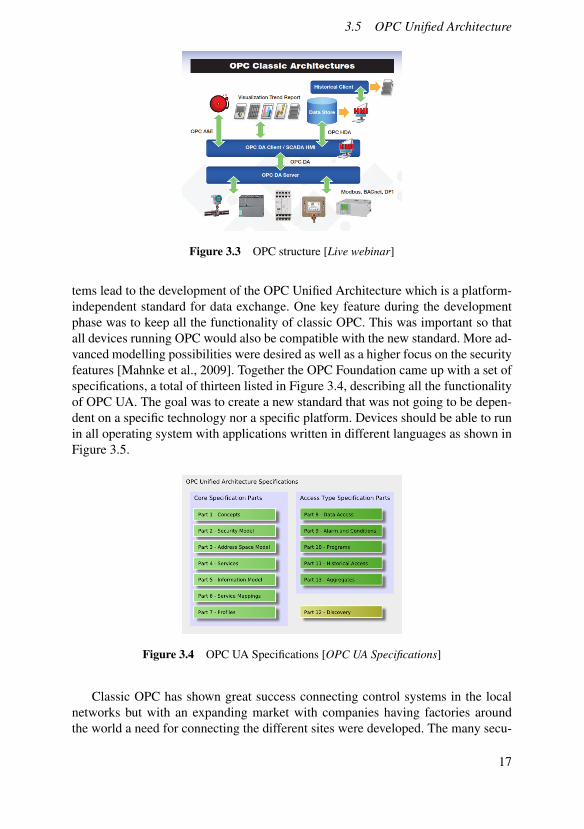
The OPC Foundation developed this standard for making information from theprocess level available for the HMIs and SCADA systems. OPC is based on theCOM and DCOM technologies from Windows and is mainly used within indus-trial automation. The OPC Foundation has developed a specification targeting threeapplication areas where the first and main one is OPC Data Access (OPC DA)that standardize the way data is made available for reading and writing. The othertwo are OPC Alarm and Events (OPC AE) and OPC Historical Data Access (OPCHDA). The information from the devices is always modelled on the server and madeavailable to the client [Mahnke et al., 2009] that could be the HMIs or the SCADAsystems. All computers running Windows OS had built in support for the COM andDCOM technologies and this was a big factor for the early success of OPC [Mahnkeet al., 2009].
OPC DA OPC DA is the most used one out of the three OPC specifications. itmakes up almost 99% of the products using OPC. As the name states OPC DA is allabout making data available for the client to access. It allows real-time monitoringof data values from different devices as in Figure 3.3.
OPC AE OPC AE offers and interface that can receive event notification andalarms as the name suggests shown in Figure 3.3. It could be for example that analarm occurs because the temperature is too high or that the level of a tank is toolow [Mahnke et al., 2009]. It also allows for sending an acknowledgement when analarm is received. The OPC AE in usually implemented as an extra feature next toOPC DA.
OPC HDA In comparison to OPC DA, OPC HDA gives access to stored datainstead of real-time data in Figure 3.3. There are three different options that OPCHDA makes available to the client. The first one is only to offer access to storedraw data. The second is to allow the client to read data from multiple variables ata specific time stamp and the last option is aggregating values from the stored datafor one or more variables [Mahnke et al., 2009].
OPC UAClassic OPC was a great success when entering the market, offering a standardizedinterface between different application in the automation industry. OPC is imple-mented on thousands of products with great results being used in more fields thanfirst planned to. Lately many vendors felt left out due to the fact that OPC onlyran on Windows OS using the ageing technologies COM and DCOM. They areno longer in development which means that OPC will soon become an outdatedstandard. These two needs together with the desire to model more complex sys-
16
3.5 OPC Unified Architecture
Figure 3.3 OPC structure [Live webinar]
tems lead to the development of the OPC Unified Architecture which is a platform-independent standard for data exchange. One key feature during the developmentphase was to keep all the functionality of classic OPC. This was important so thatall devices running OPC would also be compatible with the new standard. More ad-vanced modelling possibilities were desired as well as a higher focus on the securityfeatures [Mahnke et al., 2009]. Together the OPC Foundation came up with a set ofspecifications, a total of thirteen listed in Figure 3.4, describing all the functionalityof OPC UA. The goal was to create a new standard that was not going to be depen-dent on a specific technology nor a specific platform. Devices should be able to runin all operating system with applications written in different languages as shown inFigure 3.5.
Figure 3.4 OPC UA Specifications [OPC UA Specifications]
Classic OPC has shown great success connecting control systems in the localnetworks but with an expanding market with companies having factories aroundthe world a need for connecting the different sites were developed. The many secu-
17

Chapter 3. Theory
rity features of OPC UA, described in the specifications [OPC UA Specifications],makes it possible to connect with other systems over the internet. OPC UA allowsfor a more integrated system connecting the small embedded devices in the factorywith the servers on enterprise level. Tom Burke, the President of the OPC Founda-tion expresses it [Live webinar]:
"...from the shop floor to the top floor" [Live webinar]
3.6 Grafchart
Grafchart is a graphical programming language that has been developed by the de-partment of Automatic Control at Lund University. It works as a modelling toolbased on the theories from Grafcet, statecharts, Petri nets and also some ideasfrom other object oriented programming languages [Johnsson and Årzén, 1998].Grafchart is used for sequential procedural application and implements the state-transition paradigm. It was originally developed to be used for batch control butit has proved to work in other automation applications as well [Theorin, 2013]. Inthe beginning of the development process that started in 1991 there were two im-plementation of Grafchart where the first one was using the same name Grafchartand was built using Gensym’s expert system and the second implementation wasdone in Java and given the name JGrafchart [Theorin, 2013] The first implemen-tation using the system from Gemsym is no longer in use since it was desirable touse an open platform for the development. JGrafchart is the implementation that iscurrently used and improved.
JGrafchartJGrafchart is the Java implementation of Grafchart that is used in this thesis forcontrolling the process. The two main building blocks in JGrafchart are steps andtransitions. A step is representing a state in the process where actions can be exe-cuted or services can be called. Each step can either be active or inactive dependingon the position of the token. There are four different ways for actions or services ina step to be called. It can happen when the step is activated, which means when thetoken enters the step, or it can happen when the step is deactivated, which meanswhen the token exits the step. The actions can also be executed on a periodic basis
Figure 3.5 OPC UA platform independence [Live webinar]
18
3.6 Grafchart
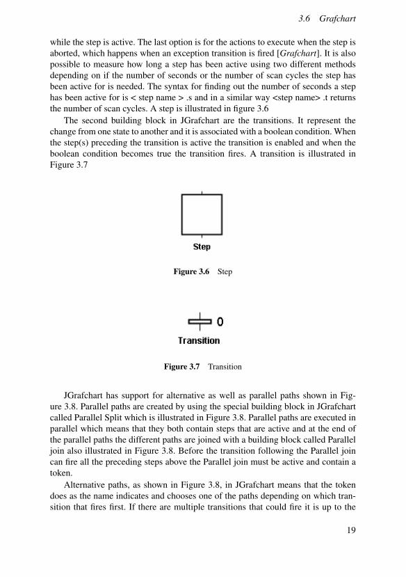
while the step is active. The last option is for the actions to execute when the step isaborted, which happens when an exception transition is fired [Grafchart]. It is alsopossible to measure how long a step has been active using two different methodsdepending on if the number of seconds or the number of scan cycles the step hasbeen active for is needed. The syntax for finding out the number of seconds a stephas been active for is < step name > .s and in a similar way <step name> .t returnsthe number of scan cycles. A step is illustrated in figure 3.6
The second building block in JGrafchart are the transitions. It represent thechange from one state to another and it is associated with a boolean condition. Whenthe step(s) preceding the transition is active the transition is enabled and when theboolean condition becomes true the transition fires. A transition is illustrated inFigure 3.7
Figure 3.6 Step
Figure 3.7 Transition
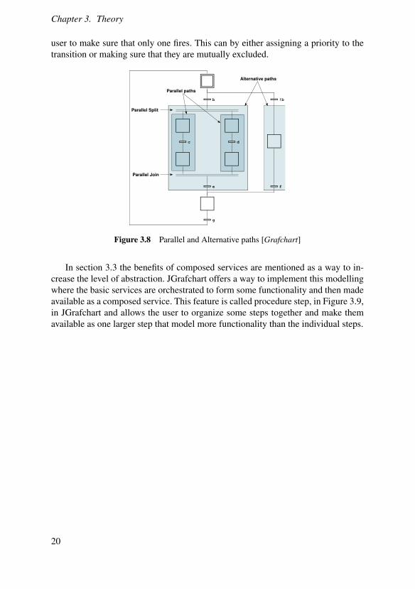
JGrafchart has support for alternative as well as parallel paths shown in Fig-ure 3.8. Parallel paths are created by using the special building block in JGrafchartcalled Parallel Split which is illustrated in Figure 3.8. Parallel paths are executed inparallel which means that they both contain steps that are active and at the end ofthe parallel paths the different paths are joined with a building block called Paralleljoin also illustrated in Figure 3.8. Before the transition following the Parallel joincan fire all the preceding steps above the Parallel join must be active and contain atoken.
Alternative paths, as shown in Figure 3.8, in JGrafchart means that the tokendoes as the name indicates and chooses one of the paths depending on which tran-sition that fires first. If there are multiple transitions that could fire it is up to the
19
Chapter 3. Theory
user to make sure that only one fires. This can by either assigning a priority to thetransition or making sure that they are mutually excluded.
b !b
c d
fe
g
Parallel Split
Parallel Join
Parallel paths
Alternative paths
Figure 3.8 Parallel and Alternative paths [Grafchart]
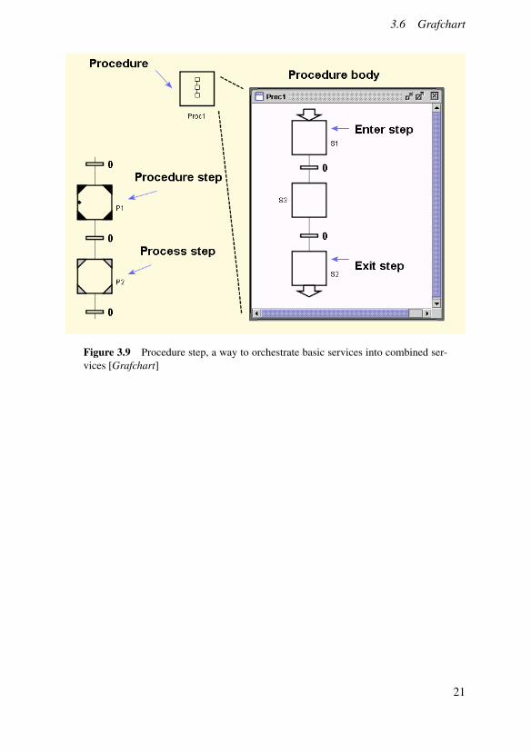
In section 3.3 the benefits of composed services are mentioned as a way to in-crease the level of abstraction. JGrafchart offers a way to implement this modellingwhere the basic services are orchestrated to form some functionality and then madeavailable as a composed service. This feature is called procedure step, in Figure 3.9,in JGrafchart and allows the user to organize some steps together and make themavailable as one larger step that model more functionality than the individual steps.
20
3.6 Grafchart
Figure 3.9 Procedure step, a way to orchestrate basic services into combined ser-vices [Grafchart]
21
4Problem description
4.1 Problem description
Manufacturing companies are doing their best trying to match the markets demandsfor a flexible production process, short set-up times and increased reusability. Thetendencies within the manufacturing industry today are shorter product life cyclesand increased complexity in the production process. This requires an automationsystem that is more flexible to fast adapt to the changes. With a more advanced au-tomation system dealing with the flexible production lines there is a growing needfor more advanced control systems. A widely spread technology for dealing withthese control systems is the use of programmable logical controllers (PLC) togetherwith field buses. The implementation of PLCs requires a lot of work because thereare no good way to connect the development of the PLC programs with the otherplanning of the production processes. The coding must be done all over again foreach new project and with more complex projects with an increased degree of pro-cess logic the requirements on the PLC programs are also increasing. The program-ming is done in the very last step of the planning phase since the PLC code is verydependent on the hardware that is being used. This is one of the major reasons whythe reusability of the PLC code is very limited. The cost of installing a new planttogether with its set-up can sum up to almost one third of the total cost over theplant’s lifetime [Jammes et al., 2005]. The production processes are changed moreoften due to the shorter life cycles of the products which calls for changes in thecontrol systems for the different automation devices more often. Re-engineeringthe code is a costly process and since each new automation device has a uniquecontrol system as much as eighty percent of the engineering effort can be spenton only reimplementing this device. With a higher level of reuseability this effortcan be spent elsewhere and much time can be saved [Jammes et al., 2005]. Howcan the development of control system be better integrated already in the planningphase and is there a way to be able to reuse the already developed system in similarprojects?
22
5OPC UA
5.1 Address space model
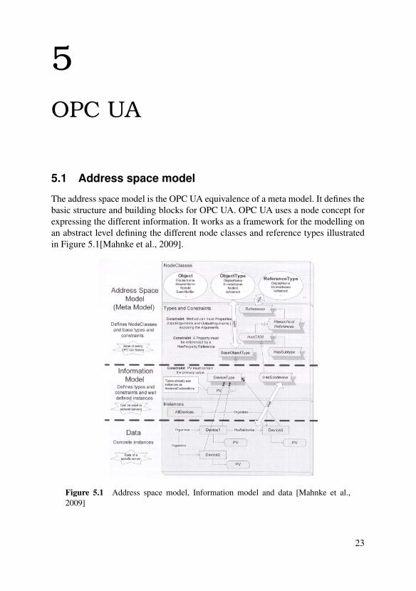
The address space model is the OPC UA equivalence of a meta model. It defines thebasic structure and building blocks for OPC UA. OPC UA uses a node concept forexpressing the different information. It works as a framework for the modelling onan abstract level defining the different node classes and reference types illustratedin Figure 5.1[Mahnke et al., 2009].
Figure 5.1 Address space model, Information model and data [Mahnke et al.,2009]
23

Chapter 5. OPC UA
5.2 Information modelling
OPC UA is all about exchanging information where the main objective for the serveris to make information available for the client to access. The information modeluses the concept of the address space model to structure the data. There are differentlevels of the information model where the top level works as a base for the other. It isthe Base OPC UA information model and contain the base node of the different nodetypes shown in Figure 5.2. Different vendors can produce their own informationmodel for their device to make sure that it is always described in the same way.Multiple information models can be used together to describe different part of theinformation made available to the client. This project focuses on the informationmodel that models the device and the services offered by the field devices. It isderived from the base information model that is already defined in the specifications[Mahnke et al., 2009] [OPC UA Specifications].
Figure 5.2 Base TypeDefinitions [Mahnke et al., 2009]
5.3 Building blocks
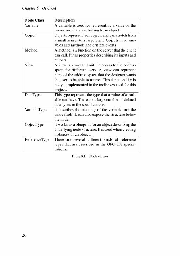
OPC UA uses a concept of nodes and references to do all the information modelling.There are eight node classes listed in Table 5.1 that are defined by the OPC UAspecifications [OPC UA Specifications]. Nodes are used to represent different enti-ties that the server is making available and references are describing the relationshipbetween two nodes. The number of node classes are predetermined and new classescannot be created by the person designing the server [Lange et al., 2010]. Each nodehas a specific number of different attributes that describes the node. There are someattributes that are the same for every node and some attributes that are dependingon the node class. The structure of a node is shown in Figure 5.3.
24

5.4 ObjectTypes vs Objects
Figure 5.3 Model of a node [OPC UA Specifications]
5.4 ObjectTypes vs Objects
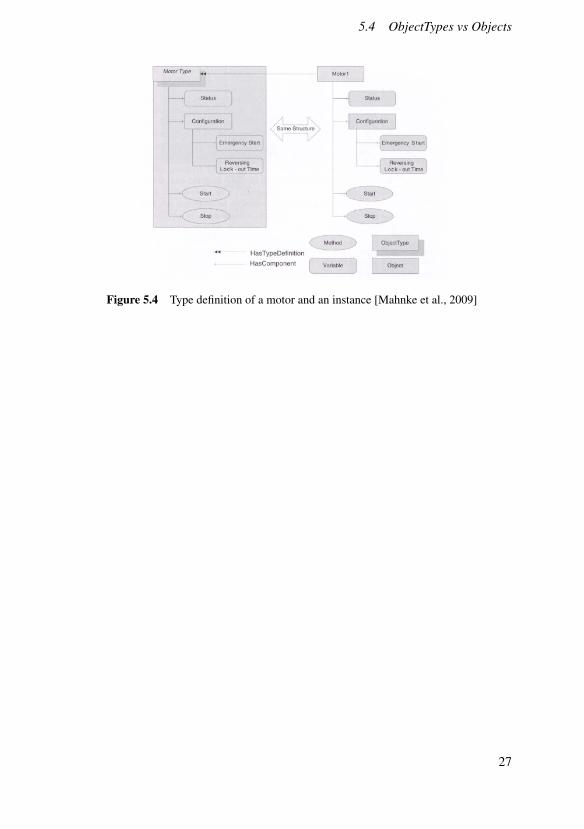
In classic OPC the only types that were possible to describe were the standard datatypes such as integers and strings. OPC UA offers the possibility to create types at anobject level. In this way it is possible to describe not only the data itself but also theinformation behind it such as from what kind of device the data is coming. Creatingtypes describing each device allows for a simple implementation of creating aninstance of this object type when an object like this needs to be modelled. OPC UAallows for the vendors to create types describing their products and these types canbe used by the developer when modelling an object of this type.
Creating types is only available for objects and variables. Methods on the otherhand are always bound to an object or an object type therefore they have no typedefinition. It is not mandatory in OPC UA to use type definitions and instead do asin classic OPC where type definitions where not available. This comes from the factthat OPC UA still has all the features supported by classic OPC.
Example of type programming on device level in OPC UAIn Figure 5.4 a type description of a motor is illustrated. It does not represent aphysical motor, it works as a blueprint of the functionality offered by this kind ofmotor. It can be seen that the motor have some kind of set-up and configurations andthen it has the methods to start and stop. This kind of type models can be supplied bythe manufacturer to allow the developer to only create an instance of the type whena motor like this need to be modelled. On the right side in Figure 5.4 an instance ofthe motor type can be seen. It represent a physical motor and has the same structureas the type definition describes [Mahnke et al., 2009].
The implementation in Figure 5.4 has its limits since the location of the node isalready determined and limits the use of this motor type to only model motors thatmatch this type. This limitation can be avoided by using a more generic design ondevice level and model all functionality as services as in DPWS.
25
Chapter 5. OPC UA
Node Class DescriptionVariable A variable is used for representing a value on the
server and it always belong to an object.Object Objects represent real objects and can stretch from
a small sensor to a large plant. Objects have vari-ables and methods and can fire events
Method A method is a function on the server that the clientcan call. It has properties describing its inputs andoutputs
View A view is a way to limit the access to the addressspace for different users. A view can representparts of the address space that the designer wantsthe user to be able to access. This functionality isnot yet implemented in the toolboxes used for thisproject.
DataType This type represent the type that a value of a vari-able can have. There are a large number of defineddata types in the specifications.
VariableType It describes the meaning of the variable, not thevalue itself. It can also expose the structure belowthe node.
ObjectType It works as a blueprint for an object describing theunderlying node structure. It is used when creatinginstances of an object.
ReferenceType There are several different kinds of referencetypes that are described in the OPC UA specifi-cations.
Table 5.1 Node classes
26
5.4 ObjectTypes vs Objects
Figure 5.4 Type definition of a motor and an instance [Mahnke et al., 2009]
27
6Tools
6.1 Introduction
This chapter will present the different tools used during this project. First a tool formodelling the information model has been used where the modelling of serviceshas been investigated. Two toolboxes have also been used for creating the serverand client for the implementation. A short introduction to each one of them is givenin this section.
• Unified Automation UaModeler
• Prosys OPC UA JAVA SDK Client
• Softing OPC UA C++ Server Development Toolkit for Linux
6.2 Unified Automation UaModeler
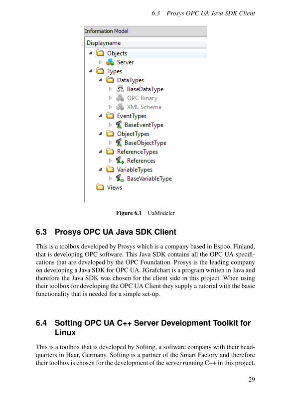
UaModeler is a tool developed by Unified Automation that offers the possibilityto create a graphical representation of the address space. It enables the user to addnodes and relationships to best describe the available information on the server.Figure 6.1 shows how that structure is formed in UaModeler. The intention is notto explain the full power of UaModeler but to give the reader a short explanation towhat functions are available and the possible benefits of using this kind of programbefore starting to develop a project and implementing OPC UA. The two main partsare the two folders Objects and Types. In the type folder the different types arelisted and based from these types instances are created and allocated as objects onthe server under the object folder in Figure 6.1. In the Object folder the physicaldevices are modelled by creating an instance of the desired type(s).
After the types are created and the physical device is described using these typesthe structure can be graphically visualized in UaModeler using the Graphic View,a built in function in UaModeler. It shows how the different objects are connectedand describes the relationship between two components.
28
6.3 Prosys OPC UA Java SDK Client
Figure 6.1 UaModeler
6.3 Prosys OPC UA Java SDK Client
This is a toolbox developed by Prosys which is a company based in Espoo, Finland,that is developing OPC software. This Java SDK contains all the OPC UA specifi-cations that are developed by the OPC Foundation. Prosys is the leading companyon developing a Java SDK for OPC UA. JGrafchart is a program written in Java andtherefore the Java SDK was chosen for the client side in this project. When usingtheir toolbox for developing the OPC UA Client they supply a tutorial with the basicfunctionality that is needed for a simple set-up.
6.4 Softing OPC UA C++ Server Development Toolkit forLinux
This is a toolbox that is developed by Softing, a software company with their head-quarters in Haar, Germany. Softing is a partner of the Smart Factory and thereforetheir toolbox is chosen for the development of the server running C++ in this project.
29

Chapter 6. Tools
Like Prosys, Softing also offers a tutorial on how the basic settings are handled intheir toolbox.
30

7Service modelling in OPCUA
7.1 Introduction
This chapter describes how services can be modelled in OPC UA, describing thebenefits of using generic devices that can host services as well as how it has beendone using the tool UaModeler.
7.2 Generic OPC UA device
Developing different types of objects is a powerful tool in OPC UA that can reducethe engineering effort when implementing a production process. There are multi-ple benefits from using type definitions of devices and creating instances of thesewhen a device needs to be modelled instead of creating a new object from scratchevery time. Using predefined types of devices such as the motor type in Figure 5.4limits the possible structure of the motor. With this approach, using the type in Fig-ure 5.4, it is necessary to always organize the methods start and stop directly underthe motor type object and the configuration settings must be in a specific object.There is no possibility to modify this structure. What if there could be a genericdevice that could represent all kind of devices with any possible structure. Thenthe device could in one implementation represent a simple motor or a simple sen-sor but in another implementation represent a smart device of a motor with built intemperature sensors. The goal is to have one generic device that has no predefinedstructure as the example with the motor type in Figure 5.4 has. In that example themotor has some structure already with methods and objects, the goal in this casewill be to have a blank device that can represent any possible device modelled inthe automation industry.
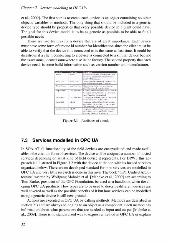
In OPC UA there are eight node classes as described in Table 5.1 that form theavailable building blocks. Each node has a certain number of predefined attributeswhere the standard ones that all node classes have are shown in Figure 7.1 [Mahnke
31
Chapter 7. Service modelling in OPC UA
et al., 2009]. The first step is to create each device as an object containing no otherobjects, variables or methods. The only thing that should be included in a genericdevice type should be properties that every possible device in a plant could have.The goal for this device model is to be as generic as possible to be able to fit allpossible needs
There are two features for a device that are of great importance. Each devicemust have some form of unique id number for identification since the client must beable to verify that the device it is connected to is the same as last time. It could bedisastrous if a client connecting to a device is connected to a similar device but notthe exact same, located somewhere else in the factory. The second property that eachdevice needs is some build information such as version number and manufacturer.
Figure 7.1 Attributes of a node
7.3 Services modelled in OPC UA
In SOA-AT all functionality of the field devices are encapsulated and made avail-able to the client in form of services. The device will be assigned a number of hostedservices depending on what kind of field device it represents. For DPWS this ap-proach is illustrated in Figure 3.2 with the device at the top with its hosted servicesorganized below. There are no developed standard for how services are modelled inOPC UA and very little research is done in this area. The book "OPC Unified Archi-tecture" written by Wolfgang Mahnke et al. [Mahnke et al., 2009] can according toTom Burke, president of the OPC Foundation, be used as a handbook when devel-oping OPC UA products. How types are to be used to describe different devices arewell covered as well as the possible benefits of it but how services can be modelledusing a generic device is still new ground.
Actions are executed in OPC UA by calling methods. Methods are described insection 7.3 and are always belonging to an object as a component. Each method hasinformation about what parameters that are needed as input and output [Mahnke etal., 2009]. There is no standardized way to express a method in OPC UA or explain
32
7.3 Services modelled in OPC UA
how they should be designed, only the signature of it. A method is something theclient can call and in return receive a result as reply. It works similar to an operationin DPWS where the operation is called with a certain input returning a calculatedresult [Theorin, 2013].
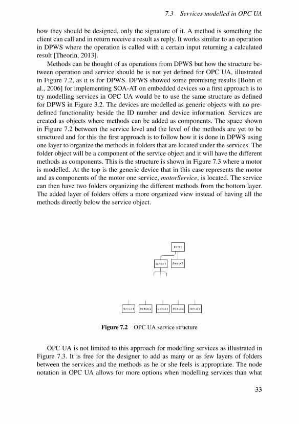
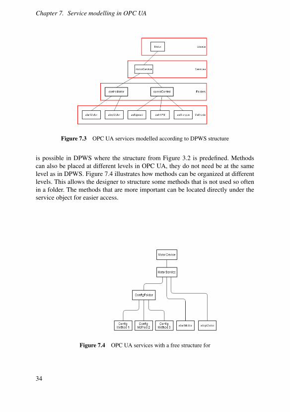
Methods can be thought of as operations from DPWS but how the structure be-tween operation and service should be is not yet defined for OPC UA, illustratedin Figure 7.2, as it is for DPWS. DPWS showed some promising results [Bohn etal., 2006] for implementing SOA-AT on embedded devices so a first approach is totry modelling services in OPC UA would be to use the same structure as definedfor DPWS in Figure 3.2. The devices are modelled as generic objects with no pre-defined functionality beside the ID number and device information. Services arecreated as objects where methods can be added as components. The space shownin Figure 7.2 between the service level and the level of the methods are yet to bestructured and for this the first approach is to follow how it is done in DPWS usingone layer to organize the methods in folders that are located under the services. Thefolder object will be a component of the service object and it will have the differentmethods as components. This is the structure is shown in Figure 7.3 where a motoris modelled. At the top is the generic device that in this case represents the motorand as components of the motor one service, motorService, is located. The servicecan then have two folders organizing the different methods from the bottom layer.The added layer of folders offers a more organized view instead of having all themethods directly below the service object.
Figure 7.2 OPC UA service structure
OPC UA is not limited to this approach for modelling services as illustrated inFigure 7.3. It is free for the designer to add as many or as few layers of foldersbetween the services and the methods as he or she feels is appropriate. The nodenotation in OPC UA allows for more options when modelling services than what
33
Chapter 7. Service modelling in OPC UA
Figure 7.3 OPC UA services modelled according to DPWS structure
is possible in DPWS where the structure from Figure 3.2 is predefined. Methodscan also be placed at different levels in OPC UA, they do not need be at the samelevel as in DPWS. Figure 7.4 illustrates how methods can be organized at differentlevels. This allows the designer to structure some methods that is not used so oftenin a folder. The methods that are more important can be located directly under theservice object for easier access.
Figure 7.4 OPC UA services with a free structure for
34

7.4 Service library
OPC UA MethodIn Figure 7.5 it is illustrated how it works when a client makes a service call to amethod. The call may contain input parameters that are specific for this method andthe method may return some specific output parameters. A method is a componentof an object and can be discovered by the client through browsing the object themethod belongs to [OPC UA Specifications] The different inputs and outputs for amethods are defined as properties of the method [OPC UA Specifications]. Thereare special browsing functions built in to the toolbox for retrieving the methods thatbelong to a node as well as commands for finding out the in- and output argumentsand how it works is described in Listing 8.18 [Prosys, 2012].
Figure 7.5 Method Service set [OPC UA Specifications]
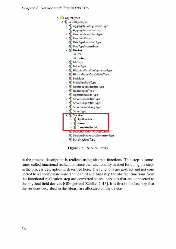
7.4 Service library
UaModeler described in section 6.2 offers the possibility to create a library likefunctionality of the services in the information model as shown in Figure 5.1. Herethe different services are listed as subtypes of the type service. These different ser-vices can be allocated on different devices to get the desired functionality.
Development of a control procedureThe services that are developed and described in the library in Figure 7.6 are usedin the process of creating control system where the first step is to create an ab-stract process description. The process description is describing what is done inthe process, not specifically how or which machine is doing what. For the processto be executable a process logic needs to be developed based on the process de-scription which means that process needs to be broken down into steps describingwhat is done where. The services must then be orchestrated as illustrated in Fig-ure 7.7 [Theorin et al., 2013] to match the process logic. The service orchestrationis done in three steps where the first step is the abstract process description describ-ing what is done step by step. The next stage is to determine how the different steps
35
Chapter 7. Service modelling in OPC UA
Figure 7.6 Service library
in the process description is realized using abstract functions. This step is some-times called functional realization since the functionality needed for doing the stepsin the process description is described here. The functions are abstract and not con-nected to a specific hardware. In the third and final step the abstract functions fromthe functional realization step are converted to real services that are connected tothe physical field devices [Ollinger and Zühlke, 2013]. It is first in the last step thatthe services described in the library are allocated on the device
36

7.4 Service library
Figure 7.7 Process description
37
8Client and Serverimplementation togetherwith JGrafchart
8.1 Introduction
In the second part of the project the goal was to create a set-up with an OPC UAserver and client and this will be explained in this chapter. On the server a simpledevice from Ficshertecknik is to be modelled and its functionality made availableto the client. How can the client connect to the server and establish a subscriptionof values representing the different sensors and the motor? The device will be con-trolled from a JGrafchart application where the monitored values from the clientwill be used to fire the transitions. This part will also explain some of the basicswhen setting up a project with an OPC UA client and server.
8.2 Fischertechnik device
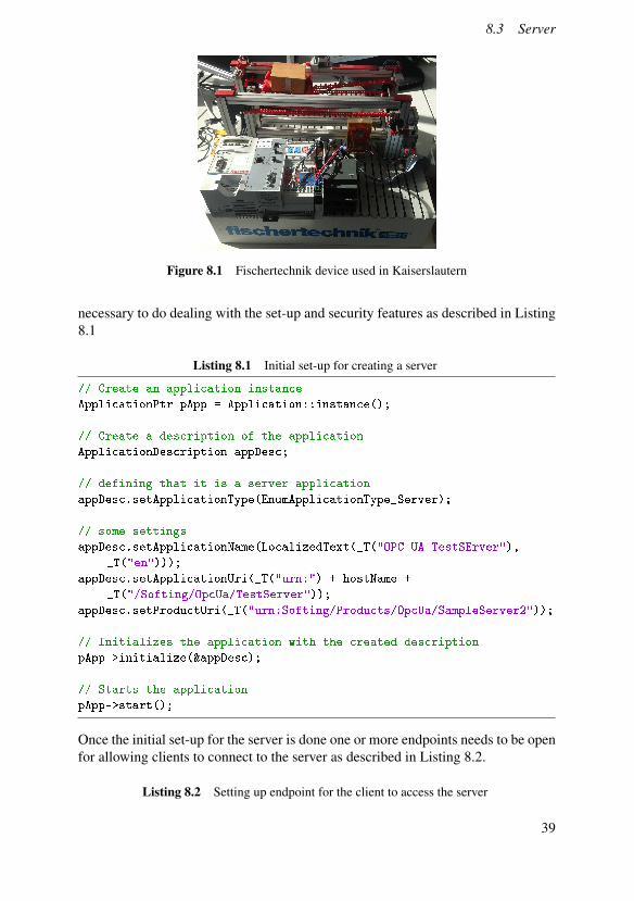
The device used for this application is a simple device from Fischertecknik thatconsist of a conveyor belt with one sensor on each side indicating when an objectis present. There is a motor driving the conveyor belt left and right. There are alsosome extra lights that can be turned on and off but they are not used. The device canbe seen in Figure 8.1.
8.3 Server
The server for this project is developed using the toolbox supplied by Softing, apartner of Smart Factory. The server is written C++ since it is supposed to runon an embedded device connected with the equipment form Fischertechnik. In thebeginning of the process of creating an OPC UA server there are some steps that are
38
8.3 Server
Figure 8.1 Fischertechnik device used in Kaiserslautern
necessary to do dealing with the set-up and security features as described in Listing8.1
Listing 8.1 Initial set-up for creating a server
// Create an application instance
ApplicationPtr pApp = Application::instance();
// Create a description of the application
ApplicationDescription appDesc;
// defining that it is a server application
appDesc.setApplicationType(EnumApplicationType_Server);
// some settings
appDesc.setApplicationName(LocalizedText(_T("OPC UA TestSErver"),
_T("en")));
appDesc.setApplicationUri(_T("urn:") + hostName +
_T("/Softing/OpcUa/TestServer"));
appDesc.setProductUri(_T("urn:Softing/Products/OpcUa/SampleServer2"));
// Initializes the application with the created description
pApp->initialize(&appDesc);
// Starts the application
pApp->start();
Once the initial set-up for the server is done one or more endpoints needs to be openfor allowing clients to connect to the server as described in Listing 8.2.
Listing 8.2 Setting up endpoint for the client to access the server
39
Chapter 8. Client and Server implementation together with JGrafchart
Server::EndpointPtr endpoint = Endpoint::create();
endpoint->setUrl(<url>);
// Setting the security level of the server
endpoint->addSecurityConfiguration(EnumMessageSecurityMode_None,
SecurityPolicyUri_None);
// Setting user settings
UserTokenPolicy userTokenPolicy;
userTokenPolicy.setPolicyId(_T("Anonymous_Policy"));
userTokenPolicy.setTokenType(EnumUserTokenType_Anonymous);
endpoint->addUserTokenPolicy(&userTokenPolicy);
// Adding endpoint to application
Application::instance()->addEndpoint(endpoint);
// Opening the endpoint to make the server available to clients
endpoint->open();
The server is now open for a client to connect to and at this stage the security isset to none. The choice to use no security at start is done to focus on first implement-ing a working set-up where values can be monitored and later when actual hardwareis used the desired security layers can be added. The server is at the moment blank,there is no information modelled in the address space. No nodes have been addedat this stage. There are three ways to insert nodes to the address space as shown inListing 8.3. The first option for inserting a node is the init(<typedefinition>) func-tion that initialize a node in the address space of the type described by the typedefinition. The second option for inserting nodes in the address space is by usingthe function insert(). The difference between the two is that for the second one theuser is responsible for adding components and references which is done automati-cally in the first case when using the type definition. The last option, insertTree(), issimilar to the insert function but it allows for the user to add a structure of nodes tothe address space.
Listing 8.3 Three ways to insert a node to the address space
// Three ways for inserting nodes in the address space.
Server::BaseNode::init( <typedefinition> );
Server::BaseNode::insert();
Server::BaseNode::insertTree();
40
8.4 Modelling a sensor on the server
8.4 Modelling a sensor on the server
There are two sensors modelled on the server and they are implemented as describedin Listing 8.4. Each sensor is a simple boolean variable that indicates whether anobject is present or not.
Listing 8.4 How to create a sensor variable on the server
Server::VariablePtr var1;
var1 = Server::Variable::create();
var1->setNodeId(NodeId(namespaceIndex,ADDRESS_SENSOR_ONE_OBJECT_PRESENT));
var1->setDisplayName(LocalizedText(_T("Sensor_1"),_T("en")));
var1->setDescription(LocalizedText(_T("this is sensor 1"),_T("en")));
var1->setDataType(Statics::DataTypeId_Boolean);
var1->init(Statics::VariableTypeId_BaseVariableType);
var1->setBrowseName(QualifiedName(_T("Sensor_1"),typeNamespaceIndex));
var1->setAccessLevel(EnumAccessLevel_CurrentRead);
// Here the sensor variable is added as a component of the device.
parentDevice->addReference(Statics::ReferenceTypeId_HasComponent,var1);
Running server on embedded deviceThe goal for the server is to run on an embedded device connected to a physical unitfrom Fischertechnik but due to limited availability of area boards the functionalityof the device is simulated using the l and r key on the keyboard for setting the valuesof each sensors, l is for changing the value of the left sensor and r is for the rightone. A complete set-up of equipment is ordered but due to long delivery times itwill be included as future work.
8.5 Client
The client is the part accessing the data made available by the server and in thisproject the client is developed in Java using the toolbox from Prosys as described insection 6.3.
SetupWhen creating and setting up a client from scratch in OPC UA there are some stepsthat are always needed to be done. They will be described briefly in the followingsection and for a more detailed description the reader is instructed to study thetoolbox specific tutorial that most developers supply with their SDK.
Since Java is the chosen platform for development of the client this sectionfocuses more on how it is done in Java. Every OPC UA application must containsome information about itself that works as a description of it for other devices,
41

Chapter 8. Client and Server implementation together with JGrafchart
Listing 8.5 describes how it is done. OPC UA has a high focus on the security andtherefore the security settings must be defined, which level of security is desired.The client needs to know the URI of the server that it will try to connect where theURI is of the format: <Protocol>://<Host>:<Port>:<ServerName> [Grafchart]
Listing 8.5 Settings needed for the ApplicationDescription
ApplicationDescription appDesc = new ApplicationDescription();
appDesc.setApplicationName(newLocalizedText(APP_NAME,Locale.ENGLISH));
appDesc.setApplicationType(ApplicationType.Client);
appDesc.setApplicationUri("urn:192.168.0.1:4880:Client");
appDesc.setProductUri("urn:smartFactory:Client");
The toolbox contains a client UaClient class that covers most of the functionalityfor connection to the server as well as the actual OPC UA communications. Theresult of this is a simple interface for the user when constructing an application.Only a few lines of code is needed as seen in Listing 8.6
Listing 8.6 How a client object is created
try{
UaClient client = new UaClient(serverUri);
}catch (URISyntaxException e){
e.printStackTrace();
}
The large focus on high security in OPC UA is easily implemented in the clientrequiring only one line of code as seen in Listing 8.7.
Listing 8.7 Available security modes in OPC UA
client.setSecurityMode(SecurityMode.NONE);
//client.setSecurityMode(SecurityMode.BASIC128RSA15_SIGN);
//client.setSecurityMode(SecurityMode.BASIC128RSA15_SIGN_ENCRYPT);
//client.setSecurityMode(SecurityMode.BASIC256_SIGN_ENCRYPT);
Once the set-up for how and where to connect is done it is only a simple com-mand for the client to connect to the server shown in Listing 8.8. Once this is doneit is possible for the client to start browsing the server to find out what kind of datathat is available.
Listing 8.8 How to connect to the server
client.connect();
It is just as simple to disconnect from the server as it is to connect. There is onlyone command for that as well as shown in Listing 8.9.
42
8.5 Client
Listing 8.9 How to disconnect from the server
client.disconnect();
BrowsingIn OPC UA all the data and services are modelled on the server and made availablefor the client to access once connected. The structure of the address space in formof nodes and references allows the client to browse from one node to the next inorder to find the desired services. The browsing always starts in the root folder andhow the nodeId for this is retrieved is shown in Listing 8.10
Listing 8.10 Identifying nodeId of Root folder
NodeId nodeId = Identifiers.Rootfolder;
The browsing of the address space is done by calling the function browse on theaddress space and using the nodeId of the current position as input as shown in List-ing 8.11. This function returns a list of reference descriptions for all the referencesleaving the current node.
Listing 8.11 How to browse the address space
List<ReferenceDescription> references =
client.getAddressSpace().browse(nodeId);
The nodeId of the target node can be found by following the reference, shown inListing 8.12 in a similar way as the browsing was done.
Listing 8.12 How to follow a reference
//action is an integer indicating the number of the chosen reference
try {
ReferenceDescription r = references.get(action);
NodeId target;
try {
target = browse(client.getAddressSpace()
.getNamespaceTable().toNodeId(r.getNodeId()));
Read & Write valuesThe client can write a value to the server and all that is needed for this is the nodeIdand the attributeId and is done as in Listing 8.13 where nodeId is the node that avalue is written to, the attribute represents the attribute of this node that is to bechanged and value is the new value that is written to the node.
43

Chapter 8. Client and Server implementation together with JGrafchart
Listing 8.13 Write value on the server
boolean status = client.writeAttribute(nodeId,attributeId,value)
There is a built in system of status codes in OPC UA where each error has a uniquestatus code that is returned when a call is made. There are many different statuscodes that could indicate if the operation was done immediately or asynchronouslyas well as status codes that indicates if something went wrong and the reason for it.A complete list of all the error messages can be found in the specifications [OPCUA Specifications]. The client can read a value on the server in two ways where thefirst one is rather simple and not so efficient. The function in Listing 8.14 only readson attribute from one node.
Listing 8.14 Simple read function for only one attribute
DataValue value = client.readAttribute(nodeId,attributeId);
It should be avoided to call the read function for an individual item. The other readfunction can do multiple reads in one call, which means it can read many attributesat once as shown in Listing 8.15.
Listing 8.15 Read for multiple attributes
client.read()
For monitoring values on the server, for instance to monitor the value of a sensor,there are better ways than to read a value over an over again to see if it has changed.Creating a subscription of a data value is the preferred way when clients needs tomonitor value changes of a variable.
SubscriptionIn OPC UA there are three different types of monitored items that a client can createa subscription of. The most common one to subscribe to is the monitoring of acertain value on the server, once again it could be the simple example with the valueof a sensor. Subscribing to the change of a variable value is considered as one ofthe most important features in OPC UA. The client can also subscribe to generatedevents from the server. The last option for the client is to subscribe to aggregatedvalues in a client specified time interval [Mahnke et al., 2009]. How a subscriptionfor the first kind is created is shown in Listing 8.16. What is executed once the valuethat is subscribed to is changed is shown in Listing 8.17.
Listing 8.16 Creating a subscription
//create subscription
if(subscription == null){
subscription = createSubscription();
44
8.5 Client
client.addSubscription(subscription);
}
// pause the monitoring while editing the subscription
subscription.setPublishingEnabled(false);
UnsignedInteger attributeId = readAttributeId();
MonitoredDataItem item = new MonitoredDataItem(nodeId, attributeId,
MonitoringMode.Reporting);
subscription.addItem(item);
//subscription is started again after that the new item is added
subscription.setPublishingEnabled(true);
subscription.setPublishingInterval(100);
if(!item.hasChangeListener(dataChangeListener)){
item.addChangeListener(dataChangeListener);
}
// After the subscriptions has been edited they are updated
subscription.updateItems();
Listing 8.17 When a change occurs on a monitored value
@Override
public void onDataChange(MonitoredDataItem sender, DataValue
prevValue, DataValue value){
// operation done when the monitored value has changed.
}
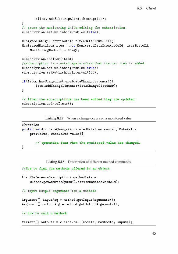
Listing 8.18 Description of different method commands
//How to find the methods offered by an object
List<ReferenceDescription> methodRefs =
client.getAddressSpace().browseMethods(nodeId):
// Input Output arguments for a method:
Argument[] inputArg = method.getInputArguments();
Argument[] outputArg = method.getOutputArguments();
// How to call a method:
Variant[] outputs = client.call(nodeId, methodId, inputs);
45
Chapter 8. Client and Server implementation together with JGrafchart
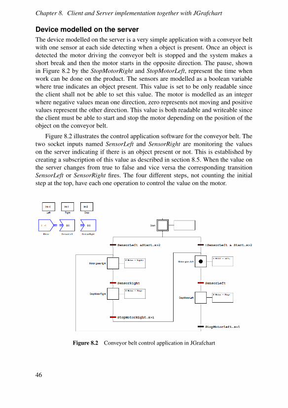
Device modelled on the serverThe device modelled on the server is a very simple application with a conveyor beltwith one sensor at each side detecting when a object is present. Once an object isdetected the motor driving the conveyor belt is stopped and the system makes ashort break and then the motor starts in the opposite direction. The pause, shownin Figure 8.2 by the StopMotorRight and StopMotorLeft, represent the time whenwork can be done on the product. The sensors are modelled as a boolean variablewhere true indicates an object present. This value is set to be only readable sincethe client shall not be able to set this value. The motor is modelled as an integerwhere negative values mean one direction, zero represents not moving and positivevalues represent the other direction. This value is both readable and writeable sincethe client must be able to start and stop the motor depending on the position of theobject on the conveyor belt.
Figure 8.2 illustrates the control application software for the conveyor belt. Thetwo socket inputs named SensorLeft and SensorRight are monitoring the valueson the server indicating if there is an object present or not. This is established bycreating a subscription of this value as described in section 8.5. When the value onthe server changes from true to false and vice versa the corresponding transitionSensorLeft or SensorRight fires. The four different steps, not counting the initialstep at the top, have each one operation to control the value on the motor.
Figure 8.2 Conveyor belt control application in JGrafchart
46
8.5 Client
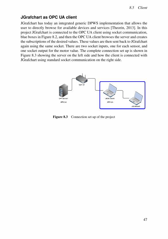
JGrafchart as OPC UA clientJGrafchart has today an integrated generic DPWS implementation that allows theuser to directly browse for available devices and services [Theorin, 2013]. In thisproject JGrafchart is connected to the OPC UA client using socket communication,blue boxes in Figure 8.2, and then the OPC UA client browses the server and createsthe subscriptions of the desired values. These values are then sent back to JGrafchartagain using the same socket. There are two socket inputs, one for each sensor, andone socket output for the motor value. The complete connection set up is shown inFigure 8.3 showing the server on the left side and how the client is connected withJGrafchart using standard socket communication on the right side.
Figure 8.3 Connection set up of the project
47

9Results
9.1 Result from service modelling
The results on how services can be modelled in OPC UA are illustrated in Figure 7.3and 7.4. The structure chosen for the objects between services and methods canfreely be organized according to the present demands. At the top is a generic device,just like for DPWS, but the structure of the hosted services are not predefined. Eachservice can have its own structure of objects with methods located at different levelsshown in Figure 7.4.
A service library has been created in UaModeler as illustrated in Figure 7.6 aswell as the type definition for the generic device. This type definition has only thebasic set up information and an unique ID number as components listed in Fig-ure 7.6. Instances of this type are created when modelling any kind of field devicein a factory. Once a generic device is instantiated the services needed for describingthe functionality of the corresponding field device are allocated as hosted serviceson the device. This is accomplished by creating an instance of a service in the libraryand locate it as a component of the device object.
9.2 Result from implementation
Using the OPC UA server together with the client to control the simulated version ofthe conveyor belt worked well. The subscriptions of the sensor values are manuallycreated by browsing the address space of the server until the desired variable islocated and chosen for a subscription. Once the subscriptions of the values werecreated the control application in JGrafchart shown in Figure 8.2 is started and thedevice is controlled. The subscriptions of sensor values on the server works welland each change is detected and the corresponding transition fires.
48
10Discussion
The goal was to investigate how services can be modelled in OPC UA and to createa library of different services. The tool UaModeler has proven to be very usefulfor this. It offers an environment where the information model can be modelled ina graphical way as in Figure 6.1. The created library of services would enable thedeveloper to reuse their work in many applications.
The generic device type together with the service library offers a way for theengineer
The desire to use a generic device for describing every possible field device in afactory can be accomplished in a similar way as for DPWS. UaModeler describedoffers a powerful way to model services and also shows a graphical representationof the information model. The benefit of starting with first modelling the servicesin UaModeler is that it offers a better overview and the services can be listed likea library shown in Figure 7.6. How the structure of the services shall be organizedmust be tested on real application to experience the pros and cons.
JGrafchart uses a graphical syntax shown in Figure 3.6 and 3.7 that is commonfrom other process control languages. This makes it a good candidate to be usedfor service orchestration to create control software. The procedure step shown inFigure 3.9 offers the possibility of creating composed services in a simple waywhich allows JGrafchart to easily model more abstract control software.
The implementation of the OPC UA server and client for controlling the devicefrom Fischertechnik using JGrafchart works well. The initial plan was to integratethe client into JGrafchart using a similar block as for DPWS. This integration isin progress and will be included as future work. Integrated support of OPC UA inJGrafchart could offer a good way into the market for JGrafchart as a tool for serviceorchestration as well as a control software.
There is not only one way to do things in OPC UA, it offers many choices forthe designer and much of the focus was spent on understanding how services can bemodelled before trying to implement one. The implementation has only been doneusing a simulated device since the device had not arrived at the end of this project.The results from the simulations indicates that subscribing to values representingthe sensors works well.
49

11Future work
The project has resulted in a working set-up with a simulated device modelled onthe OPC UA server and controlled by the client. So far the client and the JGrafchartapplication have been two separate applications connected using socket communi-cation. The next step would be to integrate the OPC UA functionality into JGrafchartin a similar way as DPWS has been integrated with a special building block avail-able under the I/O menu.
The second thing that is planned as future work is implementing the use ofmethods in OPC UA and not only read and write a value on the server.
A physical device from Fischertechnik is ordered to be used for the implemen-tation but due to long delivery time it is included as future work.
50
Bibliography
Automation World. Live webinar. URL: www.automationworld.com/elster-and - beckhoff - automation - connect - shop - floor - automation -
directly-top-floor-sap-me-opc-ua (visited on 01/21/2014).
Bohn, H., A. Bobek, and F. Golatowski (2006). “Sirena - service infrastructure forreal-time embedded networked devices: a service oriented framework for differ-ent domains”. In: Networking, International Conference on Systems and Inter-national Conference on Mobile Communications and Learning Technologies,2006. ICN/ICONS/MCL 2006. International Conference on, pp. 43–43. DOI:10.1109/ICNICONSMCL.2006.196.
Department of Automatic Control, Lund University. Grafchart. URL: http : / /control . lth . se / Research / tools / grafchart . html (visited on01/21/2014).
Jammes, F., A. Mensch, and H. Smit (2005). “Service-oriented device communi-cations using the devices profile for web services”. In: Proceedings of the 3rdInternational Workshop on Middleware for Pervasive and Ad-hoc Computing.MPAC ’05. ACM, Grenoble, France, pp. 1–8. ISBN: 1-59593-268-2. DOI: 10.1145/1101480.1101496. URL: http://doi.acm.org/10.1145/1101480.1101496.
Johnsson, C. and K.-E. Årzén (1998). “Grafchart for recipe-based batch control”.Computers and Chemical Engineering 22:12, pp. 1811–1828.
Lange, J., F. Iwanitz, and T. J. Burke (2010). OPC from Data Access to UnifiedArchitecture. VDE Verlag.
Mahnke, W., S.-H. Leitner, and M. Damm (2009). OPC Unified Architecture.Springer.
51

Bibliography
Ollinger, L. and D. Zühlke (2013). “An integrated engineering concept for themodel-based development of service-oriented control procedures”. In: Pro-ceedings of the IFAC Conference on Manufacturing Modelling, Managementand Control(MIM-2013), June 19-21, Saint Petersburg, Russian Federation.Vol. 7. IFAC PapersOnLine, pp. 1441–1446. URL: http : / / www . ifac -
papersonline.net/Detailed/60299.html.
Ollinger, L., J. Schlick, and S. Hodek (2011). “Leveraging the agility of manufac-turing chains by combining process-oriented production planning and service-oriented manufacturing”. In: Proceedings of the 18th IFAC World Congress.World Congress of the International Federation of Automatic Control (IFAC-2011), August 28 - September 2, Milan, Italy. Elsevier Science Ltd.
OPC Foundation. Opc ua specifications.
Prosys (2012). Opc ua java sdk client tutorial.
SmartFactoryKL. SmartFactoryKL. URL: http://smartfactory.dfki.uni-kl.de/en (visited on 01/21/2014).
Theorin, A. (2013). Adapting Grafchart for Industrial Automation. Licentiate The-sis ISRN LUTFD2/TFRT--3260--SE. Department of Automatic Control, LundUniversity, Sweden.
Theorin, A. and C. Johnsson (2012). “Graphical programming language support forservice oriented architecture in automation”. eng. In: Uppsala, Sweden.
Theorin, A., L. Ollinger, and C. Johnsson (2013). “Service-oriented process controlwith Grafchart and the devices profile for web services”. In: Service Orientationin Holonic and Multi-agent Manufacturing and Robotics. Ed. by T. Borangiu,A. Thomas, and D. Trentesaux. Accepted for publication. Springer.
Wikipedia (2014). Service-oriented architecture — wikipedia, the free encyclope-dia. [Online; accessed 11-January-2014]. URL: http : / / en . wikipedia .org/w/index.php?title=Service-oriented_architecture&oldid=
590048072.
52

Lund UniversityDepartment of Automatic ControlBox 118SE-221 00 Lund Sweden
Document nameMASTER´S THESISDate of issueAugust 2014Document NumberISRN LUTFD2/TFRT--5953--SE
Author(s)
Johan HagsundSupervisorAlfred Theorin, Dept. of Automatic Control, LundUniversity, SwedenCharlotta Johnsson, Dept. of Automatic Control, Lund University, Sweden (examiner)Sponsoring organization
Title and subtitle
Implementation of Service Orchestrated control procedures in OPC UA for JGrafchart
Abstract
The automation industry is facing many challenges with higher demands on their production process. Technology used today does not allow for fast changes in the production line. This thesis will investigate how services can be modelled using a new standard OPC UA for data exchange. Encapsulation of the mechatronic functions as services will allow for creating control software using a SOA approach. An experimental set-up will investigate how an OPC UA server and client are created.
Keywords
Classification system and/or index terms (if any)
Supplementary bibliographical information
ISSN and key title0280-5316
ISBN
LanguageEnglish
Number of pages1-52
Recipient’s notes
Security classification
http://www.control.lth.se/publications/