Embed Size (px)
Citation preview
University of Ulm | 89069 Ulm | Germany Faculty ofEngineering and Com-puter ScienceInstitute of Databases andInformation Systems
Implementation of a Java Frameworkfor Marker Based Detectionin Augmented RealityBachelor thesis of the University of Ulm
Presented by:Tamino P.S.M. [email protected]
Verifier:Professor Doctor Manfred Reichert
Supervisor:Marc Schickler
2013

Version October 16, 2013
c© 2013 Tamino P.S.M. Hartmann
This work is licensed under the Creative Commons. Attribution-NonCommercial-ShareAlike 3.0License. To view a copy of this license, visit http://creativecommons.org/licenses/by-nc-sa/3.0/de/or send a letter to Creative Commons, 543 Howard Street, 5th Floor, San Francisco, California,94105, USA.Satz: PDF-LATEX 2ε
Abstract
Due to the drastic increase in powerful hardware in mobile devices, it has become
possible to move Augmented Reality applications from desktop systems to their mobile
counterparts, thus also opening a wide range of new uses and possibilities. To allow fast
development of mobile Augmented Reality applications, we propose and implement a
framework that handles the heavy lifting.
This paper describes the path from design to implementation of an augmented reality
framework for the mobile Android platform. The goal is a framework for marker-based
tracking and corresponding rendering of three dimensional objects, to be usable in
any application for Android. The framework, called Imagine, will utilize OpenCV for
Android for the image processing to detect markers and OpenGL ES 2.0 to render
the corresponding 3D objects. The finished framework is also analyzed for possible
improvements and corrections.
iii

Gratitude
The author of this paper would first and foremost like to thank his supervisor Marc
Schickler for his support. Beyond that, general thanks are in order for the author’s social
support network in keeping him on track and motivated. This especially includes his
parents, Stefan and Katja Hartmann, for proof-reading the text of this paper and his
friends for continually reminding him that a deadline was quickly approaching (most
persistently Laura Irlinger).
Further thanks are due to the online developer communities surrounding OpenGL ES,
Android, and OpenCV for explanations and examples. Thanks are also due to Linux in
general for offering a sane development environment, IntelliJ IDEA for a superior and
not frustrating IDE compared to Eclipse, and Texmaker for easy LATEX.
v

Contents
1 Overview 1
1.1 Introduction . . . . . . . . . . . . . . . . . . . . . . . . . . . . . . . . . . . 1
1.2 Project Context . . . . . . . . . . . . . . . . . . . . . . . . . . . . . . . . . 3
1.3 Content of this Paper . . . . . . . . . . . . . . . . . . . . . . . . . . . . . . 3
2 Framework 5
2.1 Proposed Functionality . . . . . . . . . . . . . . . . . . . . . . . . . . . . . 5
2.2 Dependencies . . . . . . . . . . . . . . . . . . . . . . . . . . . . . . . . . 7
2.3 Limitations of Scope . . . . . . . . . . . . . . . . . . . . . . . . . . . . . . 8
2.4 General Class Diagram . . . . . . . . . . . . . . . . . . . . . . . . . . . . 10
2.5 Application Programming Interface . . . . . . . . . . . . . . . . . . . . . . 11
2.6 Usage . . . . . . . . . . . . . . . . . . . . . . . . . . . . . . . . . . . . . . 12
2.7 Implementation . . . . . . . . . . . . . . . . . . . . . . . . . . . . . . . . . 13
2.7.1 Tools and Environment . . . . . . . . . . . . . . . . . . . . . . . . 13
2.7.2 First Steps and Trials . . . . . . . . . . . . . . . . . . . . . . . . . 13
2.7.3 Implemented Algorithm . . . . . . . . . . . . . . . . . . . . . . . . 14
2.8 Complete Class Diagram . . . . . . . . . . . . . . . . . . . . . . . . . . . 18
2.9 How to Use . . . . . . . . . . . . . . . . . . . . . . . . . . . . . . . . . . . 20
3 Markers 21
3.1 Coding Scheme . . . . . . . . . . . . . . . . . . . . . . . . . . . . . . . . 22
3.2 Usage . . . . . . . . . . . . . . . . . . . . . . . . . . . . . . . . . . . . . . 23
vii
Contents
4 Results 25
4.1 Implementation . . . . . . . . . . . . . . . . . . . . . . . . . . . . . . . . . 25
4.1.1 Encountered Difficulties . . . . . . . . . . . . . . . . . . . . . . . . 26
4.1.2 Performance . . . . . . . . . . . . . . . . . . . . . . . . . . . . . . 29
4.2 Features and Capabilities . . . . . . . . . . . . . . . . . . . . . . . . . . . 32
4.2.1 Debugging Capabilities . . . . . . . . . . . . . . . . . . . . . . . . 32
4.2.2 Features . . . . . . . . . . . . . . . . . . . . . . . . . . . . . . . . 34
4.3 Application . . . . . . . . . . . . . . . . . . . . . . . . . . . . . . . . . . . 35
4.4 Comparison to similar Apps . . . . . . . . . . . . . . . . . . . . . . . . . . 36
4.4.1 Aruco . . . . . . . . . . . . . . . . . . . . . . . . . . . . . . . . . . 37
4.4.2 DroidAR . . . . . . . . . . . . . . . . . . . . . . . . . . . . . . . . . 38
5 Conclusion 39
5.1 Future Possibilities . . . . . . . . . . . . . . . . . . . . . . . . . . . . . . . 39
5.1.1 Performance . . . . . . . . . . . . . . . . . . . . . . . . . . . . . . 40
5.1.2 Features . . . . . . . . . . . . . . . . . . . . . . . . . . . . . . . . 40
5.1.3 Improvements . . . . . . . . . . . . . . . . . . . . . . . . . . . . . 41
5.1.4 Extended Possibilities . . . . . . . . . . . . . . . . . . . . . . . . . 42
5.2 Closing Statement . . . . . . . . . . . . . . . . . . . . . . . . . . . . . . . 43
viii
1Overview
1.1 Introduction
As mobile devices become more and more powerful and ubiquitous, developers contin-
ually realize new uses for them. One of the fields that is continually reinventing itself
is the field of Augmented Reality. It is the integration of information onto and into our
perception of the real world – an augmentation of our reality. To achieve this many
different methods exist [GPSR13]. Many such applications use the user’s global position
to overlay points of interest onto a camera feed; others use computer vision to track real
world objects to enable software interaction with them. Detecting real world objects is
however a non-trivial task, and thus a wide range of possibilities for accomplishing that
exist.
1
1 Overview
One of these is the usage of so-called markers – visually significant patters – to enable
fast and easy detection of objects. To enable quick and easy development of applications
that use marker-based tracking for the augmentation of our reality, this paper and the
work it covers was envisioned.
This paper represents the initial design and development work for an Android framework
to simplify the detection and usage of markers in Augmented Reality applications. The
framework shall henceforth be named Imagine to differentiate it from other similar
frameworks and the libraries it utilizes.
Imagine will initially only target applications written for Android using Java [and]. It will
utilize the OpenCV for Android library, a sub-project of the original OpenCV framework
specifically targeted for Android devices [opea]. By separating the detection and the
rendering modules within Imagine, it should be relatively easy to extend the functionality
of Imagine to other platforms and other technologies, such as desktop applications for
Linux or rendering with DirectX instead of OpenGL ES.
To develop and test the framework, we will also implement an application that relies
on Imagine for basic functionality. The application will allow for the real-time viewing of
virtual objects on top of a marker and be used to test and evaluate Imagine. This shall
prove the capability and initial concept of the framework and also serve as a starting
point for any future derivative work.
This paper consists of all the work done around the actual implementation. We will
look at the basic requirements of the framework. Basic necessities will be listed and
reviewed. We’ll also present a proposal for the structure of the framework. Difficulties
that arose during development will also be documented, along with possible solutions
and commentary. At the end we will also shortly compare Imagine to other frameworks
to put it into perspective.
Apart from the programmatic development of the framework and the final review of
our work, we will also deliver at least basic documentation for the framework. For the
framework this will include a Javadoc [doc] file for the completed code and a basic tutorial
for usage. The implementing application should be self explanatory, although care will
be taken to ensure a low learning hurdle for using it.
2
1.2 Project Context
1.2 Project Context
This paper is the bachelor thesis of Tamino Hartmann, written at the Faculty of Engineer-
ing and Computer Science [fac] at the Institute of Databases and Information Systems at
the University of Ulm [ulm], Germany. The work commissioned is to create a framework
for fast and easy integration of marker-based tracking for possible future projects within
the institute, thus decreasing repetitive re-implementation of the same features and
allowing a faster development time for implementing applications. The supervisor was
Marc Schickler and the examiner was Professor Doctor Manfred Reichert.
1.3 Content of this Paper
Chapter 2 presents the preliminary work done for finding an algorithm and subsequently
for implementing it. We then shortly take a look at what encompasses our markers for
Imagine in chapter 3.
Chapter 4 presents our encountered difficulties, implemented features, and a comparison
to other, similar frameworks. We conclude with chapter 5, where we step back and give
a more general outlook on possible future work.
3

2Framework
In this section, we take a close look at the proposed structure and capabilities of the
framework, Imagine. We will then discuss the implementation and its difficulties.
2.1 Proposed Functionality
The framework shall have two primary capabilities: first, it should enable fast and easy
access to the 3D pose calculated from the detected marker. Second, given a digital 3D
model to display, it should be capable of returning a rendering of the object within the
scene on top of the live preview, correctly positioned.
Generally, the framework shall work as in the following. Once the framework is running,
OpenCV reads the camera frame directly from the camera. This frame is copied to the
5
2 Framework
worker threads that will detect markers. The original unaltered frame is passed back up
to be shown as the background of the later rendering.
These worker threads are where the computational expensive part of actually detecting
the marker happens. Using the OpenCV for Android library, we detect markers and
calculate their three dimensional pose. All detected markers are put into a list with the
important attached information, such as the corresponding identification number of the
detected marker.
This list is passed back to the main controlling element of the framework. Here it can be
passed directly to listening classes if that option was chosen. This is done when only the
marker information is required and not a rendering. If not, the list is filtered for only those
markers that the user wants to track. These trackables have to have been registered
beforehand by the user. Then the model information is attached to all detected trackable
assets and passed down to the rendering part of the framework. Here, this filtered and
supplemented list is used to render all objects onto the correct positions with the correct
perspective modifications on top of the camera image.
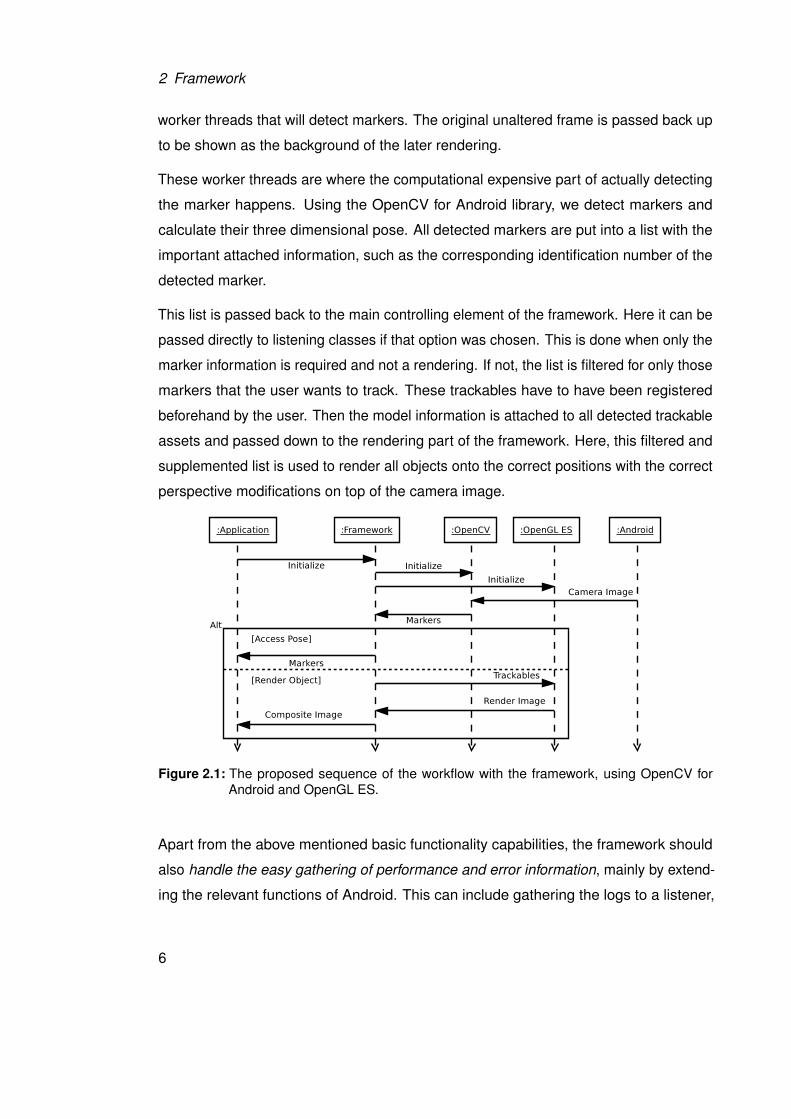
Figure 2.1: The proposed sequence of the workflow with the framework, using OpenCV forAndroid and OpenGL ES.
Apart from the above mentioned basic functionality capabilities, the framework should
also handle the easy gathering of performance and error information, mainly by extend-
ing the relevant functions of Android. This can include gathering the logs to a listener,
6
2.2 Dependencies
bypassing the Android logging mechanism, and any further functionality that could be
useful.
Figure 2.1 shows the proposed sequence of events of Imagine, and where data can be
input or read. As proposed, the framework should offer a wide variety of uses, without
being overly complex from an outside perspective. Another important aspect we want
to make possible is the possibility of changing all the more important parameters during
runtime, such as switching the model or adding a new marker. This should allow a less
restrictive usage of the framework and any derived apps as a result.
2.2 Dependencies
Primary dependency is of course an Android environment, given that it is the target
platform for the framework. The framework is written in Java with Android specific syntax
and structure. Aside from the basic requirements, the framework will depend mainly on
two external software solutions.
The first is OpenCV, an open source collection of computer vision and machine learning
software. Imagine makes use of the Java-based port, called OpenCV for Android [opea].
To use the framework on Android, the OpenCV Manager [opeb] needs to be installed
alongside the application using the framework, as the marker detection relies on it. The
OpenCV Manager offers the best version of OpenCV for Android for each Android device
according to its specifications and capabilities.
Apart from OpenCV for Android, OpenGL ES is used for the rendering of the 3D objects
to the display. For this dependency, nothing has to be considered from an application that
would use the framework, as the mobile version of OpenGL is already built into Android.
According to the capabilities of the developer device used, we choose to use OpenGL
ES 2.x. This has the added advantage that at the time of development, a minority of
devices support OpenGL ES 3.x anyway. At the same time using version (OpenGL ES
1.x) would broaden the pool of compatible devices by an insignificant amount.
7
2 Framework
2.3 Limitations of Scope
In the following we will look at the features required of the framework for it to be
considered feature complete and basically usable. Some nice-to-have features will
also be listed, meaning features that will not be implemented but could possibly be
interesting for future development. For completeness we will also take a short look at
features that are possibly too difficult to do, would take too much extra time, and or would
require significant work.
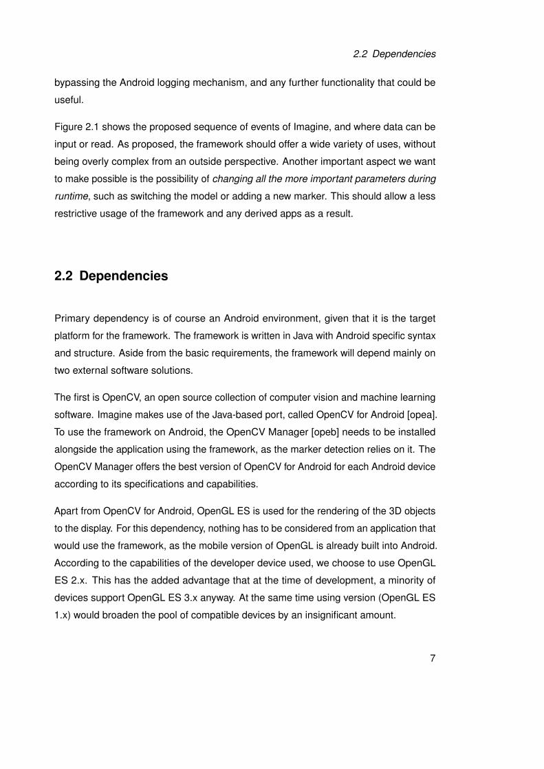
To clarify the scope of the proposed framework, all features that will be delivered are
described within table 2.1.
Debug messaging The framework should be easy to debug and allow simple access to
status messages
Manage trackers Allow to add and remove trackers during runtime
Read position data Give the possibility of accessing the raw data returned from the
OpenCV interface, bypassing the rendering step
Configuration Allow easy visualization for various aspects of the framework
Multi-threading Allow computationally expensive tasks to run multi-threaded
Helpful functions Offer functions for marker creation and object loading to decrease
external work required to use Imagine
Table 2.1: This table lists the required features for the framework to be considered completelyfunctional.
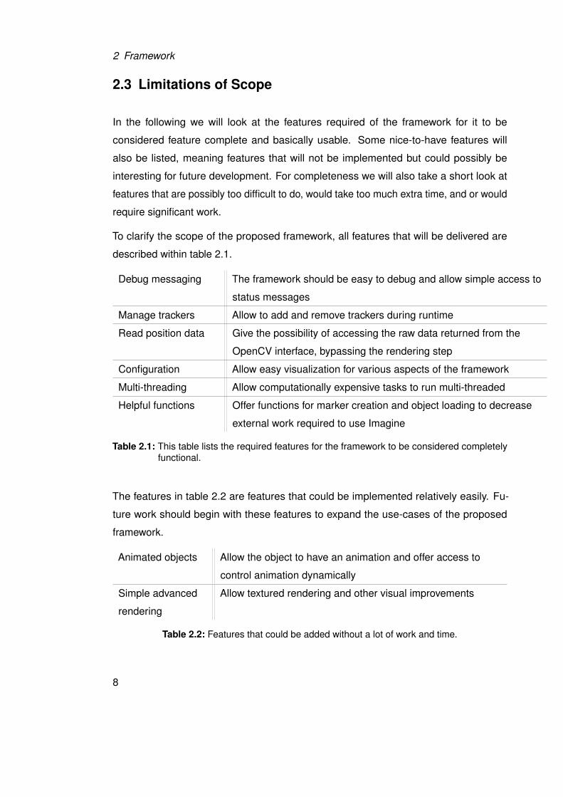
The features in table 2.2 are features that could be implemented relatively easily. Fu-
ture work should begin with these features to expand the use-cases of the proposed
framework.
Animated objects Allow the object to have an animation and offer access to
control animation dynamically
Simple advanced
rendering
Allow textured rendering and other visual improvements
Table 2.2: Features that could be added without a lot of work and time.
8
2.3 Limitations of Scope
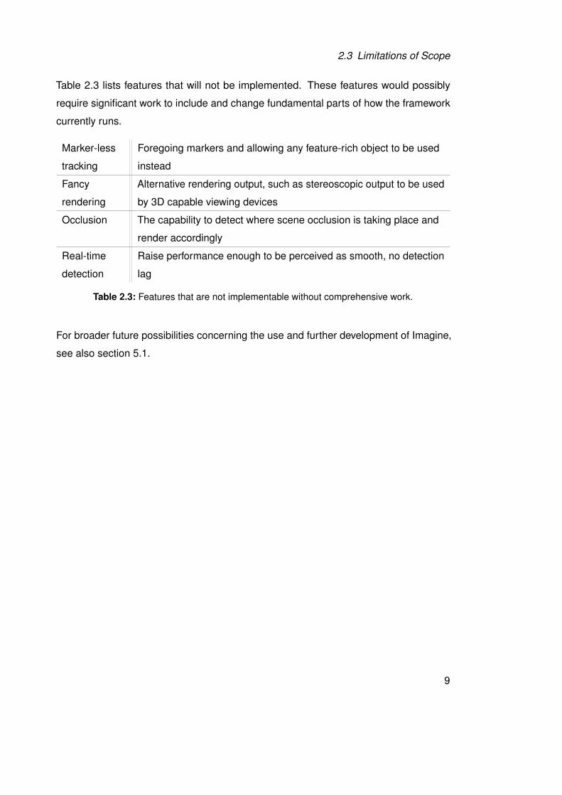
Table 2.3 lists features that will not be implemented. These features would possibly
require significant work to include and change fundamental parts of how the framework
currently runs.
Marker-less
tracking
Foregoing markers and allowing any feature-rich object to be used
instead
Fancy
rendering
Alternative rendering output, such as stereoscopic output to be used
by 3D capable viewing devices
Occlusion The capability to detect where scene occlusion is taking place and
render accordingly
Real-time
detection
Raise performance enough to be perceived as smooth, no detection
lag
Table 2.3: Features that are not implementable without comprehensive work.
For broader future possibilities concerning the use and further development of Imagine,
see also section 5.1.
9
2 Framework
2.4 General Class Diagram
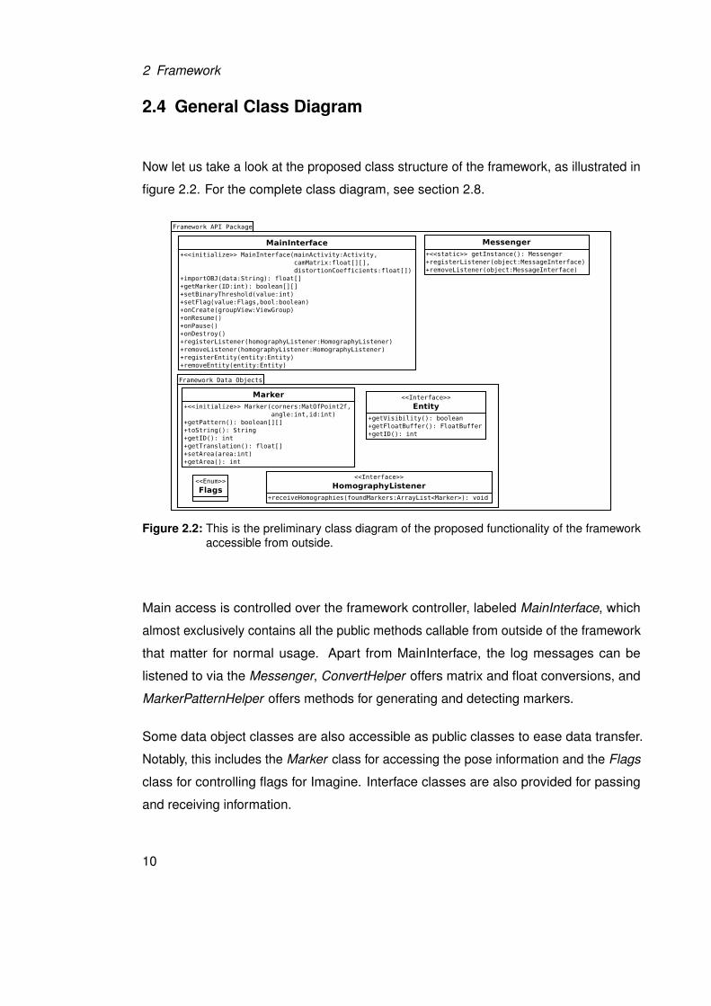
Now let us take a look at the proposed class structure of the framework, as illustrated in
figure 2.2. For the complete class diagram, see section 2.8.
Figure 2.2: This is the preliminary class diagram of the proposed functionality of the frameworkaccessible from outside.
Main access is controlled over the framework controller, labeled MainInterface, which
almost exclusively contains all the public methods callable from outside of the framework
that matter for normal usage. Apart from MainInterface, the log messages can be
listened to via the Messenger, ConvertHelper offers matrix and float conversions, and
MarkerPatternHelper offers methods for generating and detecting markers.
Some data object classes are also accessible as public classes to ease data transfer.
Notably, this includes the Marker class for accessing the pose information and the Flags
class for controlling flags for Imagine. Interface classes are also provided for passing
and receiving information.
10
2.5 Application Programming Interface
2.5 Application Programming Interface
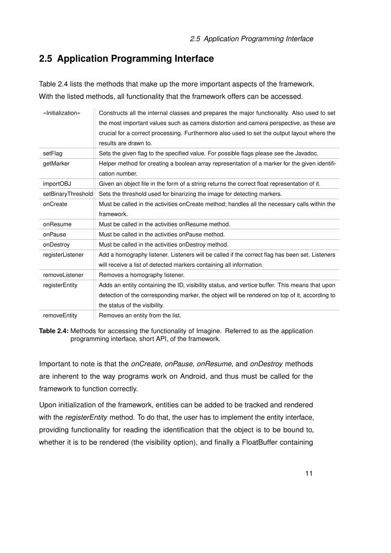
Table 2.4 lists the methods that make up the more important aspects of the framework.
With the listed methods, all functionality that the framework offers can be accessed.
«Initialization» Constructs all the internal classes and prepares the major functionality. Also used to set
the most important values such as camera distortion and camera perspective, as these are
crucial for a correct processing. Furthermore also used to set the output layout where the
results are drawn to.
setFlag Sets the given flag to the specified value. For possible flags please see the Javadoc.
getMarker Helper method for creating a boolean array representation of a marker for the given identifi-
cation number.
importOBJ Given an object file in the form of a string returns the correct float representation of it.
setBinaryThreshold Sets the threshold used for binarizing the image for detecting markers.
onCreate Must be called in the activities onCreate method; handles all the necessary calls within the
framework.
onResume Must be called in the activities onResume method.
onPause Must be called in the activities onPause method.
onDestroy Must be called in the activities onDestroy method.
registerListener Add a homography listener. Listeners will be called if the correct flag has been set. Listeners
will receive a list of detected markers containing all information.
removeListener Removes a homography listener.
registerEntity Adds an entity containing the ID, visibility status, and vertice buffer. This means that upon
detection of the corresponding marker, the object will be rendered on top of it, according to
the status of the visibility.
removeEntity Removes an entity from the list.
Table 2.4: Methods for accessing the functionality of Imagine. Referred to as the applicationprogramming interface, short API, of the framework.
Important to note is that the onCreate, onPause, onResume, and onDestroy methods
are inherent to the way programs work on Android, and thus must be called for the
framework to function correctly.
Upon initialization of the framework, entities can be added to be tracked and rendered
with the registerEntity method. To do that, the user has to implement the entity interface,
providing functionality for reading the identification that the object is to be bound to,
whether it is to be rendered (the visibility option), and finally a FloatBuffer containing
11
2 Framework
vertice locations and color information. The use of the FloatBuffer might not seem
intuitive at first glance, however it allows the framework to handle the rendering all on its
own, greatly simplifying the usage of the framework.
2.6 Usage
The finished framework can track multiple markers in a single instance. In fact, it
tracks all markers it finds from the beginning, only filtering out the ones that the user is
interested in before rendering. This allows comparatively easy use of multiple, separately
tracked entities. However, this also has a significant drawback: as the framework is
computationally expensive, multiple markers can quickly degrade its performance, even
if the user is only interested in a single marker – see also section 4.1.2.
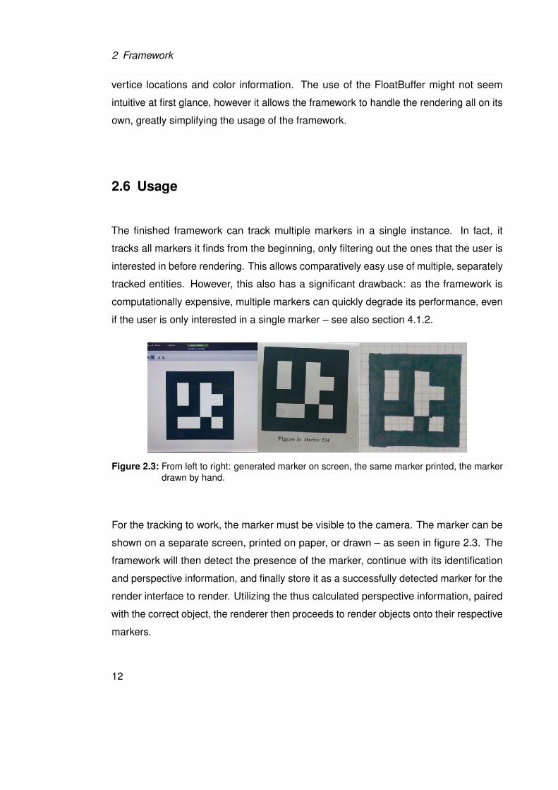
Figure 2.3: From left to right: generated marker on screen, the same marker printed, the markerdrawn by hand.
For the tracking to work, the marker must be visible to the camera. The marker can be
shown on a separate screen, printed on paper, or drawn – as seen in figure 2.3. The
framework will then detect the presence of the marker, continue with its identification
and perspective information, and finally store it as a successfully detected marker for the
render interface to render. Utilizing the thus calculated perspective information, paired
with the correct object, the renderer then proceeds to render objects onto their respective
markers.
12
2.7 Implementation
2.7 Implementation
The following section describes in more detail the implementation of the framework.
Here we will look at the tools used, the process of arriving at a satisfactory algorithm,
and then how it works.
Due to performance considerations and access to low level hardware access, we decided
not to implement a hybrid framework, such as a HTML5 application in a native container,
but a native application [SSP+13].
2.7.1 Tools and Environment
We developed Imagine on a Linux Mint Debian Edition powered computer with the
IntelliJ IDEA IDE [ide]. The development device was connected via USB debugging for
rapid iterative coding. Javadoc was written directly into the code and then generated to
readable format via internal IntelliJ IDEA tools.
For further documentation, we utilized Dia [dia] for generating diagrams, Umbrello [umb]
for the class diagrams, Texmaker [tex] for LATEXcreation, and Git [gita] for revision control.
Imagine was developed with the target of running smoothly on a Nvidia Tegra 3 processor.
The development device is the Transformer Prime, a 10” tablet from ASUS [dev]. This
means that the framework should run smoothly on a 1.6 Ghz Quadcore ARM processor
rendering to a 1280 by 800 pixel screen.
2.7.2 First Steps and Trials
First we implemented a test project to experiment with OpenCV for Android to collect
data on possible solutions and problems. This test project was later worked into the
finished framework once a suitable algorithm had been found.
At first, a feature-based detection approach for markers was tried. That meant that feature
detection was used on the marker, resulting in a cloud of key feature points. These can
then theoretically be located in an image from which we have likewise extracted feature
13
2 Framework
points. However, this method proved to be too computationally expensive considering that
we would then still need to identify the marker and calculate the geometric information.
Initial tests only for detecting feature points in a live camera view yielded framerates
below 2 frames per second. This was deemed insufficient for a realtime use of the
finished product.
Initialized by that, further detailed research turned up a better solution based on the
method used by the comparable Aruco [aru] framework. By comparing the performance
of the marker-based approach of Aruco, the feature-based approach was discarded
in favor of a marker-based approach, as it promised to offer a significant performance
increase.
2.7.3 Implemented Algorithm
This section describes in detail how we detect, identify, and calculate the perspective
transformation of the markers in Imagine. These steps are done for each frame, leverag-
ing the image processing capabilities of OpenCV. It results in a list of detected markers
with their transformation matrices.
14
2.7 Implementation
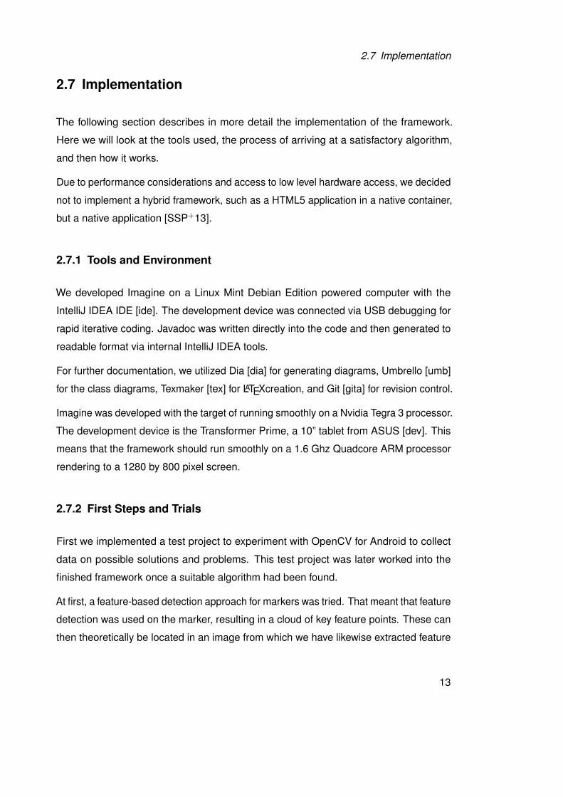
Figure 2.4: A typical result of the binarization step.
The first step is to reduce the color image into a binary image. To do this, we take the
gray-scaled image that we receive from OpenCV and threshold it against a constant
value. As we are interested in highly contrasted regions as our markers are monochrome,
this threshold was chosen relatively low. Figure 2.4 shows the result of the operation.
Alternative methods are available, but require some more work. These are using
the Canny edge detection algorithm [Can86] or an adaptive threshold. Both of these
however only detect edges as black on white lines. These can also be used to get
possible contours but result in two contours for a marker – one on each side of the line,
effectively an inside and outside contour. Therefore we filter these out, leaving only the
outer contours in place.
This binary image is suitable for fast detection of all contours within the image. The
detected contours are then filtered for size, as any contour that represents a marker
below a certain size will be too small to safely and correctly identify. The filtering
also improves performance as it removes much contour noise, therefore decreasing
15
2 Framework
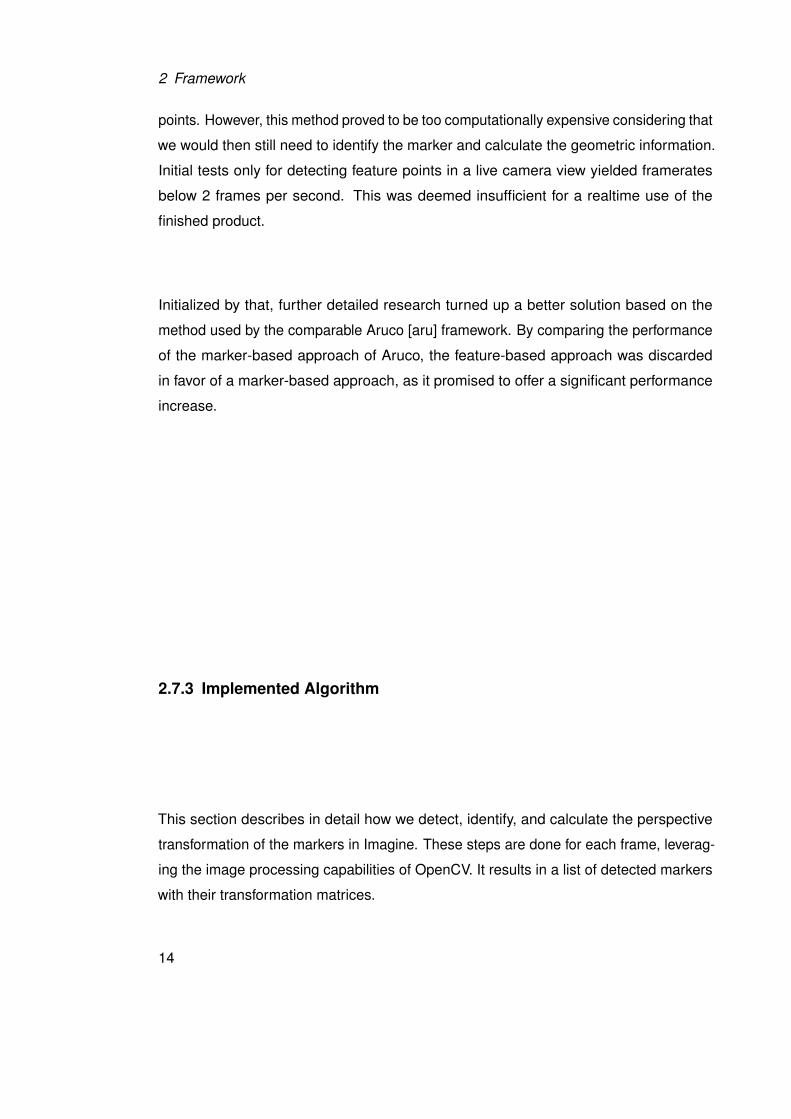
our workload for further steps. Figure 2.5 shows the detected contours, filtered and
overlayed on the original image.
Figure 2.5: The detected contours.
Next we calculate polynomial approximations for all remaining contours. We can then fil-
ter the polynomial objects based on two criteria for our markers. We only take polynomial
objects with four corners and those which form a convex hull.
Now that we have a selection of detected perspective rectangles that might be markers,
we sample all candidates for a black border. To do this, we first have to de-warp the
part of the image that is confined by the rectangles. This is done to decrease sampling
difficulty and decreases speed only by an insignificant amount. The now square texture
is then used in the following steps, of which the first is to check that the candidates have
a valid black border. Next we check for the orientation bits: if we find these, we can be
comparatively sure that we have a valid marker and can continue to its identification. If
the detection of orientation fails (meaning that we do not find a pattern of three white
and one black inner corner block), we consider the candidate to be invalid. Now all that
remains is the marker identification, which is done by sampling the remaining inside bits
16
2.7 Implementation
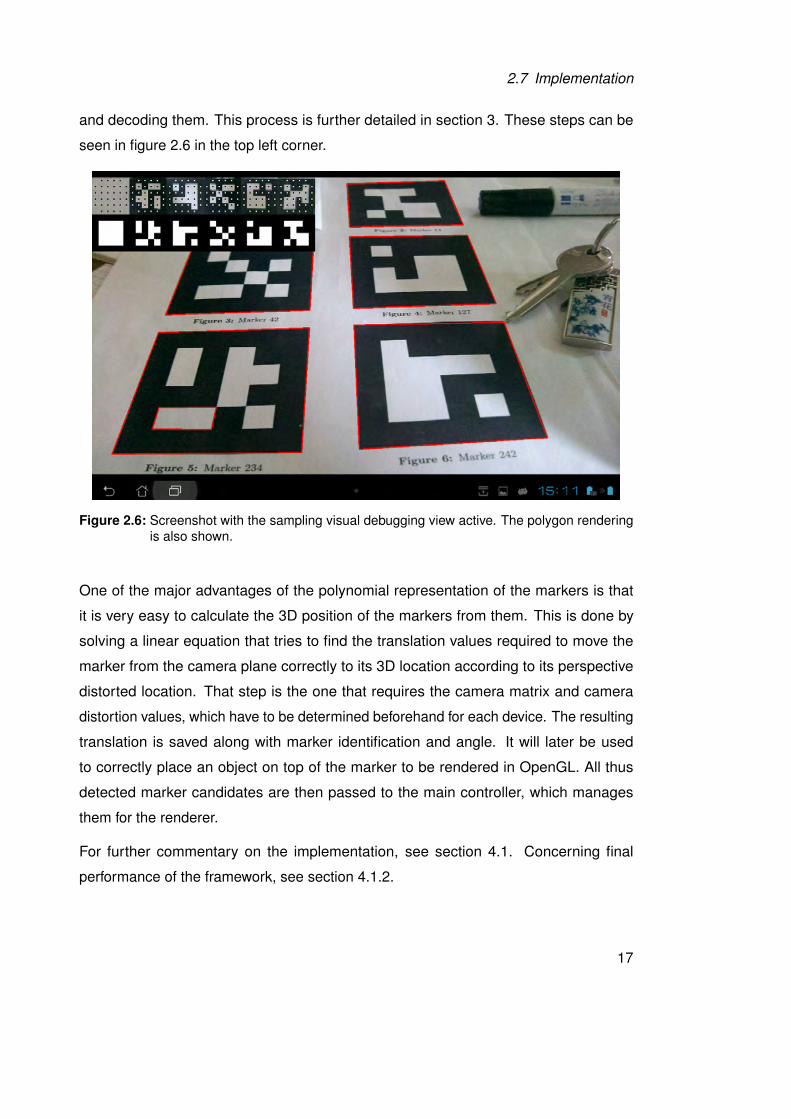
and decoding them. This process is further detailed in section 3. These steps can be
seen in figure 2.6 in the top left corner.
Figure 2.6: Screenshot with the sampling visual debugging view active. The polygon renderingis also shown.
One of the major advantages of the polynomial representation of the markers is that
it is very easy to calculate the 3D position of the markers from them. This is done by
solving a linear equation that tries to find the translation values required to move the
marker from the camera plane correctly to its 3D location according to its perspective
distorted location. That step is the one that requires the camera matrix and camera
distortion values, which have to be determined beforehand for each device. The resulting
translation is saved along with marker identification and angle. It will later be used
to correctly place an object on top of the marker to be rendered in OpenGL. All thus
detected marker candidates are then passed to the main controller, which manages
them for the renderer.
For further commentary on the implementation, see section 4.1. Concerning final
performance of the framework, see section 4.1.2.
17
2 Framework
2.8 Complete Class Diagram
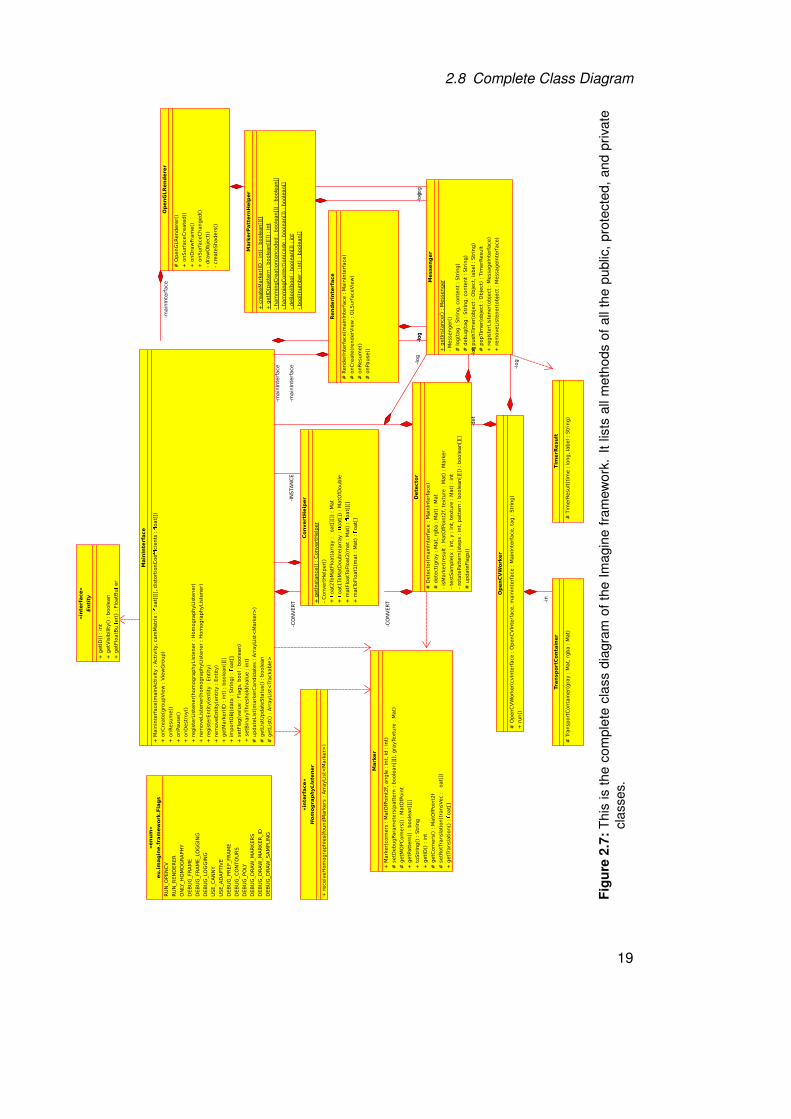
Figure 2.7 shows the complete class diagram of the finished framework.
MainInterface encapsulates all the primary functionality within the framework that is
required to work with if from an application. Apart from managing all the other classes
on startup and closure, it also handles the information exchange between them and
the application itself. It also enables the management of the entities and their assigned
trackables. MainInterface also handles any inter-system compatibility that the passage of
information between the renderer and interface require, such as the filtering of detected
markers for trackables that are to be rendered.
The Messenger class allows easy and quick access to any debugging, logging, or error
messages to outside classes via a listener principle.
The OpenGLRenderer implements the functions that take the list of detected trackables
and renders their objects onto the position given by the pose estimation. This class also
implements all functionality for the rendering types and 3D drawing functions that are
required.
The OpenCVWorker is a single thread that continually takes an input image and tries
to detect all markers in it. The functionality itself however rests in the Detector class;
this class only handles the logical functions surrounding the multithreading and work
delegation.
The Detector class is where the main detection code lies. The algorithm was thus
extracted from other classes to allow a clean differentiation in functionality. Here, the
main OpenCV work is done. Detector also implements a few internal methods for the
detection work that would be ill suited to lay elsewhere.
The above proposed system should enable an easily extensible build for the framework
while retaining a simplistic use case. It should, in theory, be relatively easy to exchange
either the worker threads or the render class to enable the framework to run beyond
Android. That would enable the framework to run on normal personal computers using
the full-fledged version of OpenGL or possibly DirectX.
18
2.8 Complete Class Diagram
ConvertH
elper
+ g
etI
nsta
nce()
: C
onvert
Help
er
- C
onvert
Help
er(
)
+
oat2
ToM
atF
loat(
arr
ay :
oat[
][])
: M
at
+
oat1
ToM
atD
ouble
(arr
ay :
oat[
]) :
MatO
fDouble
+ m
atF
loatT
oFlo
at2
(mat
: M
at)
:
oat[
][]
+ m
atT
oFlo
at1
(mat
: M
at)
:
oat[
]
Detector
# D
ete
cto
r(m
ain
Inte
rface :
Main
Inte
rface)
# d
ete
ct(
gra
y :
Mat,
rgba :
Mat)
: M
at
- is
Mark
er(
result
: M
atO
fPoin
t2f,
textu
re :
Mat)
: M
ark
er
- te
stS
am
ple
(x :
in
t, y
: int,
textu
re :
Mat)
: in
t
- ro
tate
Patt
ern
(ste
ps :
in
t, p
att
ern
: b
oole
an[]
[])
: boole
an[]
[]
# u
pdate
Fla
gs()
«interface»
Entity
+ g
etI
D()
: int
+ g
etV
isib
ilit
y()
: b
oole
an
+ g
etF
loatB
uer(
) :
Flo
atB
uer
«enum»
eu.imagine.framework.Flags
RU
N_O
PEN
CV
RU
N_R
EN
DER
ER
ON
LY_H
OM
OG
RA
PH
Y
DEB
UG
_FR
AM
E
DEB
UG
_FR
AM
E_LO
GG
ING
DEB
UG
_LO
GG
ING
USE_C
AN
NY
USE_A
DA
PTIV
E
DEB
UG
_PR
EP_FR
AM
E
DEB
UG
_C
ON
TO
UR
S
DEB
UG
_PO
LY
DEB
UG
_D
RAW
_M
AR
KER
S
DEB
UG
_D
RAW
_M
AR
KER
_ID
DEB
UG
_D
RAW
_S
AM
PLIN
G
«interface»
HomographyListener
+ r
eceiv
eH
om
ogra
ph
ies(f
oundM
ark
ers
: A
rrayLis
t<M
ark
er>
)
MainInterface
+ M
ain
Inte
rface(m
ain
Acti
vit
y :
Acti
vit
y,
cam
Matr
ix :
oat[
][],
dis
tort
ionC
oe
cie
nts
:
oat[
])
+ o
nC
reate
(gro
upV
iew
: V
iew
Gro
up)
+ o
nR
esum
e()
+ o
nPause()
+ o
nD
estr
oy()
+ r
egis
terL
iste
ner(
hom
ogra
phyLis
tener
: H
om
ogra
phyLis
tener)
+ r
em
oveLis
tener(
hom
ogra
ph
yLis
tener
: H
om
ogra
ph
yLis
tener)
+ r
egis
terE
nti
ty(e
nti
ty :
Enti
ty)
+ r
em
oveEnti
ty(e
nti
ty :
En
tity
)
+ g
etM
ark
er(
ID :
int)
: b
oole
an[]
[]
+ im
port
OB
J(data
: S
trin
g)
: oat[
]
+ s
etF
lag(v
alu
e :
Fla
gs,
bool :
boole
an)
# u
pdate
Lis
t(m
ark
erC
andid
ate
s :
Arr
ayLis
t<M
ark
er>
)
# g
etL
istU
pdate
Sta
tus()
: b
oole
an
# g
etL
ist(
) :
Arr
ayLis
t<Tr
ackable
>
Marker
+ M
ark
er(
corn
ers
: M
atO
fPoin
t2f,
an
gle
: int,
id :
in
t)
# s
etD
ebugPara
mete
rs(p
att
ern
: b
oole
an[]
[],
gra
yTe
xtu
re :
Mat)
# g
etM
OPC
orn
ers
() :
MatO
fPoin
t
+ g
etP
att
ern
() :
boole
an[]
[]
+ t
oStr
ing()
: S
trin
g
+ g
etI
D()
: int
# g
etC
orn
ers
() :
MatO
fPoin
t2f
# s
etR
otT
ransla
tion(t
ran
sVec :
oat[
])
+ g
etT
ran
sla
tion()
:
oat[
]
MarkerPatternHelper
+ c
reate
Mark
er(
ID :
int)
: b
oole
an[]
[]
+ g
etI
D(p
att
ern
: b
oole
an[]
[])
: in
t
- ham
min
gC
reati
on(e
ncoded :
boole
an[]
) :
boole
an[]
- ham
min
gC
orr
ecti
on(c
ode :
boole
an[]
) :
boole
an[]
- deB
ool(
bool :
boole
an[]
) :
int
- bool(
num
ber
: in
t) :
boole
an[]
Messenger
+ g
etI
nsta
nce()
: M
essenger
- M
essen
ger(
)
# log(t
ag :
Str
ing,
conte
nt
: Str
ing)
# d
ebug(t
ag :
Str
ing,
conte
nt
: Str
ing)
# p
ush
Tim
er(
obje
ct
: O
bje
ct,
label :
Str
ing)
# p
opTim
er(
obje
ct
: O
bje
ct)
: T
imerR
esult
+ r
egis
terL
iste
ner(
obje
ct
: M
essageIn
terf
ace)
+ r
em
oveLis
tener(
obje
ct
: M
essageIn
terf
ace)
OpenCVWorker
# O
penC
VW
ork
er(
cvIn
terf
ace :
OpenC
VIn
terf
ace,
main
Inte
rface :
Main
Inte
rface,
tag :
Str
ing)
+ r
un
()
RenderInterface
# R
enderI
nte
rface(m
ain
Inte
rface :
Main
Inte
rface)
# o
nC
reate
(renderV
iew
: G
LSu
rfaceV
iew
)
# o
nR
esum
e()
# o
nPause()
Tim
erResult
# T
imerR
esult
(tim
e :
long,
label :
Str
ing)
TransportC
ontainer
# T
ransport
Conta
iner(
gra
y :
Mat,
rgba :
Mat)
OpenGLRenderer
# O
penG
LR
endere
r()
+ o
nSurf
aceC
reate
d()
+ o
nD
raw
Fra
me()
+ o
nSurf
aceC
hanged()
- dra
wO
bje
ct(
)
- cre
ate
Shaders
()
-CO
NV
ERT
-CO
NV
ERT
-main
Inte
rface
-log
-log
-log
-det
-log
-main
Inte
rface
-log
-in
-main
Inte
rface
-log
-IN
STA
NC
E
-log
+ s
etB
inary
Thre
shold
(valu
e :
int)
Figu
re2.
7:T
his
isth
eco
mpl
ete
clas
sdi
agra
mof
the
Imag
ine
fram
ewor
k.It
lists
allm
etho
dsof
allt
hepu
blic
,pro
tect
ed,a
ndpr
ivat
ecl
asse
s.
19
2 Framework
2.9 How to Use
Using the framework is very easy. Simply create an instance of the MainInterface class
of the framework either in the constructor or in the onCreate method of the activity where
the application is run from. After creating the instance, the onCreate method of the
framework must be called within the activity’s own onCreate method. To create the
framework, an Android GroupView is required. Here it will place the camera view and the
view responsible for rendering the detected objects. Also required are the camera values
for the target device. These can either be calculated, copied from device information, or
detected with an application like camera-calibration [cal]. Now all that remains is to also
call onPause, onResume, and onDestroy in the respective methods of the activity via
the framework.
The framework offers some helper functions to shift some workload away from the user.
These should allow the usage of the framework to be very quick to learn and implement,
without having to understand how the framework works internally.
One such helper function is the creation of correct markers in the form of a binary array.
This can be used one-off to create a printable set of markers, or during use of the
framework for internal representation of markers. The method takes the identification
number and generates the complete marker for it, including border, orientation bits, and
Hamming encoding.
Another helper function loads a 3D model file and converts it to the correct representation
to be used with the entity class. This method takes a 3D model file and converts it
to a float array, which can easily be converted to the FloatBuffer object used by the
framework.
20
3Markers
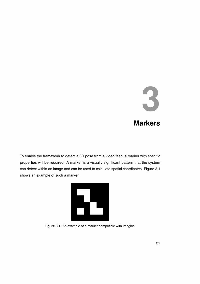
To enable the framework to detect a 3D pose from a video feed, a marker with specific
properties will be required. A marker is a visually significant pattern that the system
can detect within an image and can be used to calculate spatial coordinates. Figure 3.1
shows an example of such a marker.
Figure 3.1: An example of a marker compatible with Imagine.
21
3 Markers
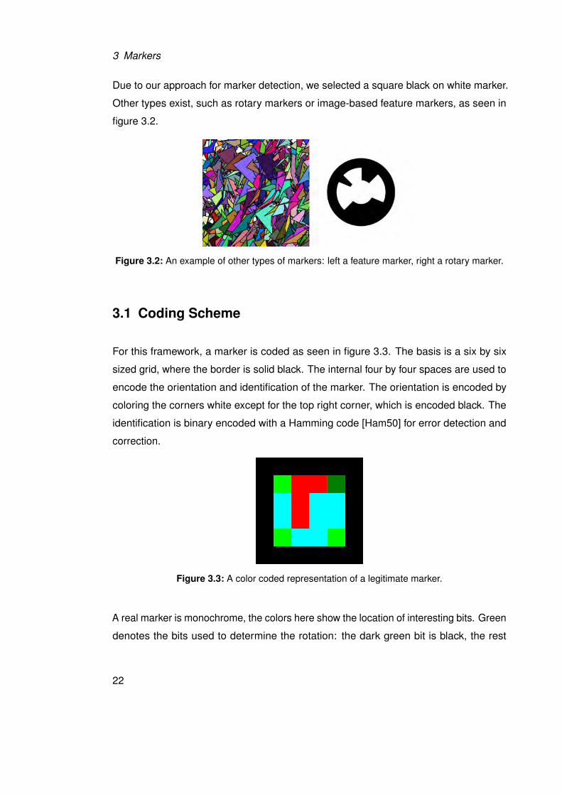
Due to our approach for marker detection, we selected a square black on white marker.
Other types exist, such as rotary markers or image-based feature markers, as seen in
figure 3.2.
Figure 3.2: An example of other types of markers: left a feature marker, right a rotary marker.
3.1 Coding Scheme
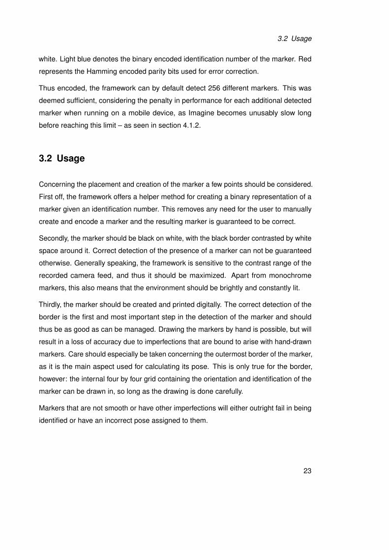
For this framework, a marker is coded as seen in figure 3.3. The basis is a six by six
sized grid, where the border is solid black. The internal four by four spaces are used to
encode the orientation and identification of the marker. The orientation is encoded by
coloring the corners white except for the top right corner, which is encoded black. The
identification is binary encoded with a Hamming code [Ham50] for error detection and
correction.
Figure 3.3: A color coded representation of a legitimate marker.
A real marker is monochrome, the colors here show the location of interesting bits. Green
denotes the bits used to determine the rotation: the dark green bit is black, the rest
22
3.2 Usage
white. Light blue denotes the binary encoded identification number of the marker. Red
represents the Hamming encoded parity bits used for error correction.
Thus encoded, the framework can by default detect 256 different markers. This was
deemed sufficient, considering the penalty in performance for each additional detected
marker when running on a mobile device, as Imagine becomes unusably slow long
before reaching this limit – as seen in section 4.1.2.
3.2 Usage
Concerning the placement and creation of the marker a few points should be considered.
First off, the framework offers a helper method for creating a binary representation of a
marker given an identification number. This removes any need for the user to manually
create and encode a marker and the resulting marker is guaranteed to be correct.
Secondly, the marker should be black on white, with the black border contrasted by white
space around it. Correct detection of the presence of a marker can not be guaranteed
otherwise. Generally speaking, the framework is sensitive to the contrast range of the
recorded camera feed, and thus it should be maximized. Apart from monochrome
markers, this also means that the environment should be brightly and constantly lit.
Thirdly, the marker should be created and printed digitally. The correct detection of the
border is the first and most important step in the detection of the marker and should
thus be as good as can be managed. Drawing the markers by hand is possible, but will
result in a loss of accuracy due to imperfections that are bound to arise with hand-drawn
markers. Care should especially be taken concerning the outermost border of the marker,
as it is the main aspect used for calculating its pose. This is only true for the border,
however: the internal four by four grid containing the orientation and identification of the
marker can be drawn in, so long as the drawing is done carefully.
Markers that are not smooth or have other imperfections will either outright fail in being
identified or have an incorrect pose assigned to them.
23

4Results
This section provides a commentary of the implementation work of the framework. We
will also take a closer look at the performance of the finished framework and where
improvements can be made in the future. To allow our work to be put into perspective,
we will also compare the framework with the Aruco framework. For that we implemented
a basic application that implements the functionality of Imagine.
4.1 Implementation
Here we will take a look at the process of implementing Imagine. First we will discuss
difficulties and hardships endured during actual coding. Then we will take a closer look
at the performance of the completed framework.
25
4 Results
4.1.1 Encountered Difficulties
The first major difficulty we encountered upon beginning the implementation was the
user generated documentation of the Java OpenCV for Android framework in the form of
questions and answers or tutorials. The probable cause for this is most likely due to the
fact that OpenCV was originally written for desktop applications using C++. That means
that there are two major differences between the more widely used and documented
version of the framework compared to the version used for this project. The first is that
one of the goals of our work was to write a Java framework, thus encouraging that we use
the Java wrapper for OpenCV – therefore making the majority of C++ resources moot
and hard to use. The second difference is due to the fact that our framework’s platform
was to be Android, for which a few small differences existed compared to the normal
use of OpenCV – such as the use of OpenCV via the elegant solution of a separate
application, the OpenCV manager. These two differences seem to have been sufficient
in decreasing the usage of the Java port of OpenCV enough that documentation and
accessible tutorials and examples proved to be far in between. This forced development
to rely all too often on examples written for other platforms and programming languages.
Luckily however the framework syntax is consistent, although the used data types are
not always transferable. Thus such translation work was possible but difficult.
But not only unofficial documentation is lacking: official documentation in the form of
documentation for the application programming interface and official tutorials are, for all
intents, almost non existent at the time of this paper. Comparably to the lacking user
generated documentation, this can be mitigated by using material intended for C++. C++
documentation is also all there is for the Javadoc used within the IDE. It is not easy
working in Java with C++ code as Javadoc, with further text mostly not relevant to the
problems encountered when coding with it.
While we’re on the topic of the C++ base of OpenCV, allow us to criticize the single most
frustrating aspect of using OpenCV: the matrix object data type, short mat. Mats are
used within OpenCV as a one-size-fits-all solution for any data ranging from vector points
that represent polygons to multi-channel images in various more or less used formats.
26
4.1 Implementation
While it was still easy to recognize the RGBA format1 that the framework receives the
camera image in, using the correct conversions and the correct mat subtypes in the
principle work thread within Imagine proved to be very frustrating. First we encountered
difficulties with the conversion of different image formats to other formats, an operation
that costs a good bit of processing power and time. Thankfully, we were able to work
around any conversions by parallel usage of multiple mats whose results are used on
one another to retain a higher overall speed.
Then another difficulty emerged while using the OpenCV function to calculate polygons
for detected contours within an image. The method for these polygons returns these in a
special mat subtype that is specialized for floating point numbers. However, the methods
we then required to work with these polygons required the polygons in a normal mat, thus
forcing us to convert from one type of mat to another. Again this problem could largely
be mitigated by converting as little as possible, although the base conversion proved to
be one of the smaller problems in the overall context of speed within the Imagine worker
threads. Furthermore, there exist no methods for determining the type and allocation of
channels within a mat. While not being able to check for these properties forced a clean
usage of the data class within Imagine and thus probably increased speed somewhat,
such methods are crucial for learning the correct usage of mat and certainty of stored
data type. Writing and reading data with mats is also something that requires faith, as
no checks for sanity can be performed on the data. For example, the method for reading
a single coordinate returns a double array – always, even when using the mat for binary
images (in which case a boolean would suffice), luminance images (possibly a short
data type), or as an integer matrix (integers). The returned value then has to be cast
to the (hopefully) correct data type – and if we made a mistake somewhere along the
line and the mat doesn’t contain the data we expect it to contain, we have no tools that
would help us catch that mistake. We therefore kindly suggest that OpenCV for Android
make use of the Java generics mechanism, as we believe that would start to reduce the
confusion surrounding mats.
1RGBA stands for, respectively: red, green, blue, alpha. This depicts the order and type of channels for animage.
27
4 Results
A further difficulty proved to be the debugging of errors while programming the worker
threads within Imagine. This came from the fact that OpenCV runs in C++ even on
Android and tracing errors to their source thus proved difficult. Often only careful
consideration of error messages and stack traces in the depths of the Android log
allowed any progress to be made in tracing a bug, although mostly trial and error proved
to be the primary method of correcting these errors. Problems debugging errors were
also due to the paradigm differences in error handling between how Java in general does
it (using so-called exceptions) and C++ does it (using integers as error codes). OpenCV
for Android does not cast the numeric error codes into equivalent Java exceptions,
instead leaving them as-is. Furthermore, the numerical error codes proved to be very
generic in their implications. An example of this can be found with the error code we
mostly fought with, which was 215. That numerical error can (and does!) mean anything
from incorrect mat sizes to incorrect number of channels. A quick search also showed
that the very same code is also used to signal unimplemented methods within OpenCV
itself.
While on the topic of paradigm differences: another difficulty we encountered with
OpenCV for Android was the difference in coding styles. With this we mean for example
that the result of a method was not returned, but instead called by reference2. Due to the
existence of exceptions, this is usually done differently when using Java. While generally
more of a nuisance than a source of error, it would be helpful if the wrapper took care of
the paradigm shift between Java and the C++ interface, thus freeing developers from
having to work with two paradigms in parallel.
Generally speaking, OpenCV for Android proved usable for this work, but with some
difficulty, as can be seen by the lengthy dissection here. OpenGL ES proved to relatively
trivial to use, notably because of the wealthy online resources in the form of extensive
documentation and multiple tutorials. The only bigger difficulties encountered while
working with OpenGL ES were using multidimensional math for the matrix operations
and how to get the renderer to render to a transparent layer.
2This stems from the way C++ usually does error handling by returning numerical error codes. The resultis written into a referenced data class, freeing the return call for passing back numerically coded error orsuccess messages.
28
4.1 Implementation
4.1.2 Performance
Here, we will take a brief look at the general performance of the Imagine framework. All
numbers that will be given are approximations only, as we did not statistically analyze
them. For a more in depth look of Imagine’s performance, further work can be done as
necessary.
Frames per Second
To give the following numbers a frame of reference, here some numbers concerning the
general speed of the Android platform, and the OpenGL ES and OpenCV utilization on it.
OpenCV captures the preview frame of the camera from Android for the base frame
from which all processing originates. This means that the speed at which it does this is
the first important reference for all further values. The speed of this operation proves
to be the first limiting factor: due to how Android camera capture works, the preview
only offers 15 frames per second. This was measured by simply showing the image
as received through OpenCV, meaning that there was no overhead work being done.
This has some strong implications for the Imagine framework: however much the work
done can be optimized, it will never be capable of running faster than that. As humans
only begin to see a smooth video upwards of approximately 20 frames per second – for
perfectly smooth video however at least 60 frames per second – this places Imagine
already outside the range of smooth output.
Android itself renders the interface at 60 frames per second3. OpenGL ES also easily
achieves 60 frames per second, although it is to note that the graphic pipeline has the
advantage of serious hardware acceleration. Of course the speed at which OpenGL ES
will render a scene for the Imagine framework is highly dependent on the complexity of
the models, although that should not be a limiting factor for some time yet.
The comparison of these two limiting factors shows that Imagine is mainly performance
dependent on the OpenCV for Android framework. Newer versions of it should theo-
retically be able to increase the speed up to the framerate of the camera preview. To3As of Android 4.1.
29
4 Results
achieve even higher speeds, the speed at which Android fetches the camera preview
must be increased, which could happen with newer devices and or newer version of
Android. All of these possible speed increases however lie outside of the influence of
the Imagine framework.
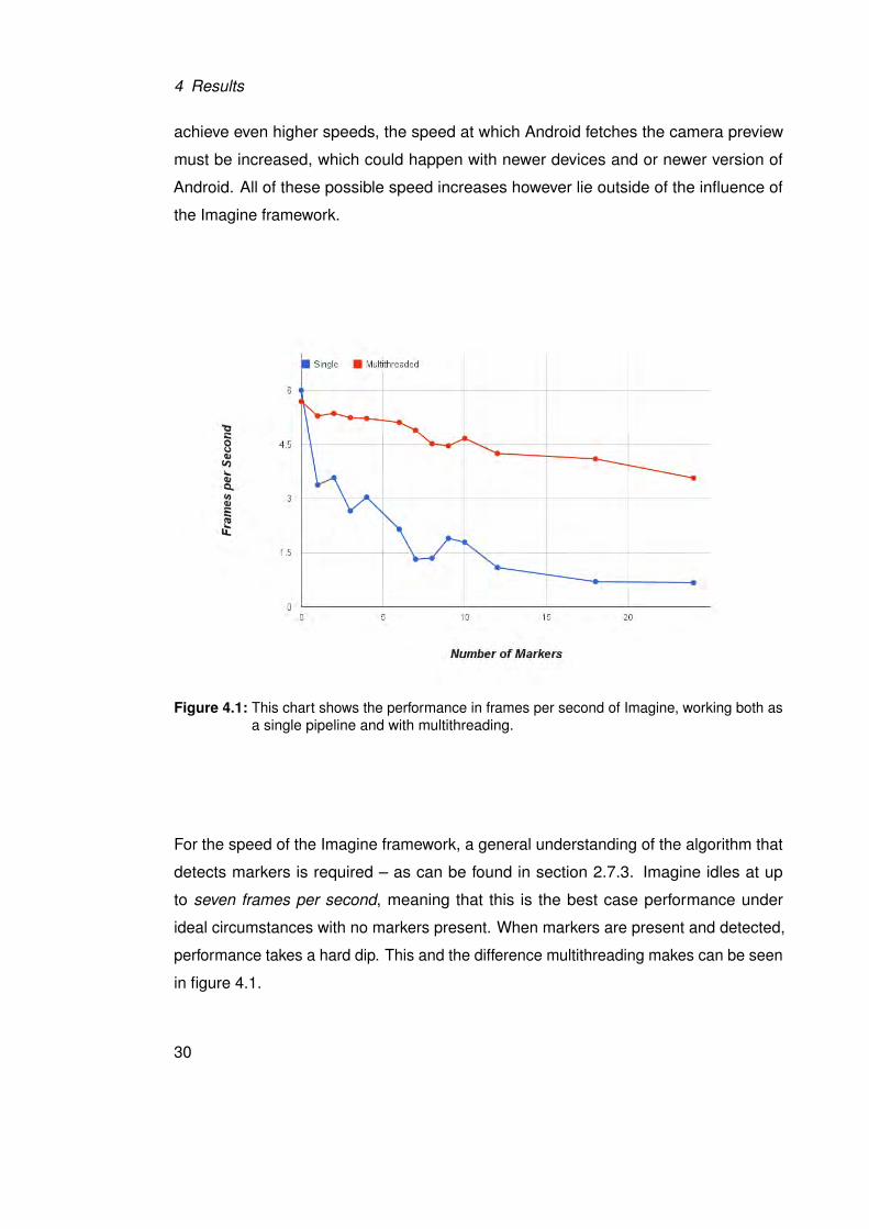
Figure 4.1: This chart shows the performance in frames per second of Imagine, working both asa single pipeline and with multithreading.
For the speed of the Imagine framework, a general understanding of the algorithm that
detects markers is required – as can be found in section 2.7.3. Imagine idles at up
to seven frames per second, meaning that this is the best case performance under
ideal circumstances with no markers present. When markers are present and detected,
performance takes a hard dip. This and the difference multithreading makes can be seen
in figure 4.1.
30
4.1 Implementation
Speed of Operations in Detector
The first performance sensitive operation is the conversion of the input image into a
binary image. The default method with a static threshold takes around 8 ms. It is
significantly faster than adaptive thresholding with 88 ms. However it does not work
reliably in low contrast images or in high dynamic ranges within an image.
Next is the operation that finds all contours from the binary image. This operation is a
vital part of the algorithm and can not easily be exchanged for some other operation.
The cost of finding contours varies strongly on the binary image, but generally takes
around 22 ms.
Now Imagine has to process each contour separately, as each could be a marker. This
step is where most of the performance is siphoned from. In total these operations take
around 100 ms, with a high variance for the number of markers.
For each found contour, we calculate the polynomial approximation and use it to filter
out any polygons that aren’t convex and don’t have 4 corners. This step takes about
3 ms. Imagine then calculates the perspective transform and applies it to dewarp the
texture of the marker candidate to allow sampling. Using the RGBA input mat, OpenCV
does this step in 12 ms. Originally however we require a grayscale image at this point;
however it turns out that OpenCV has no hardware acceleration for dewarping grayscale
mats on a Tegra CPU, such as the developer machine has. Using the grayscale image
would impose a more hefty performance cost.
If the contour is still a valid candidate at this point, Imagine tries to detect a marker
from it and the dewarped texture. This method takes anywhere from 5 ms to 30 ms,
depending on whether the candidate is valid in terms of sampling its properties from
the texture (meaning valid border, orientation, and identification marks). If a marker is
rotated, then the correction of the identification pattern takes additional time, as rotating
matrices is computationally expensive.
Now only one step remains for a complete marker detection: calculating the perspective
transformations. This is done for all detected markers, but luckily is relatively fast
31
4 Results
compared to other operations. OpenCV takes 2 ms to calculate the data for every
marker.
4.2 Features and Capabilities
In this section, we will take a look at the implemented features of Imagine. This includes
basic features that are required for basic usability and capabilities for debugging various
algorithm stages.
4.2.1 Debugging Capabilities
Imagine offers some easy options for selective debugging beyond the log output on
Android. Specifically for debugging the visual pipeline we implemented some options so
that pinpointing an error is comparatively easy. Setting debugging up is done via flags
and should only be done before calling the onCreate method.
The first option we offer is to activate a more verbose logging mode, where Imagine logs
quite a bit more information concerning possible errors – for example, the status of the
hamming decoding upon marker detection. On par with that one can also activate frame
per frame time logging, where Imagine will log the time each detection and rendering
step takes.
Going into the visual debugging it is important to note that marker detection is partially
suspended. In any case Imagine deactivates multithreading to enable the output to
be shown – as seen in section 4.1.2, this decreases performance quite a bit. Once in
visual debugging mode, three main aspects can be shown. The first option that can
be activated shows the binary picture. This can be used to check whether the chosen
binarization method is working correctly.
Another output that can be chosen is to let Imagine draw the detected contours. This
option can be used to detect errors within the contour detection that arise from the
method used to binarize the image.
32
4.2 Features and Capabilities
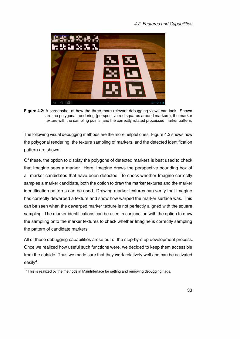
Figure 4.2: A screenshot of how the three more relevant debugging views can look. Shownare the polygonal rendering (perspective red squares around markers), the markertexture with the sampling points, and the correctly rotated processed marker pattern.
The following visual debugging methods are the more helpful ones. Figure 4.2 shows how
the polygonal rendering, the texture sampling of markers, and the detected identification
pattern are shown.
Of these, the option to display the polygons of detected markers is best used to check
that Imagine sees a marker. Here, Imagine draws the perspective bounding box of
all marker candidates that have been detected. To check whether Imagine correctly
samples a marker candidate, both the option to draw the marker textures and the marker
identification patterns can be used. Drawing marker textures can verify that Imagine
has correctly dewarped a texture and show how warped the marker surface was. This
can be seen when the dewarped marker texture is not perfectly aligned with the square
sampling. The marker identifications can be used in conjunction with the option to draw
the sampling onto the marker textures to check whether Imagine is correctly sampling
the pattern of candidate markers.
All of these debugging capabilities arose out of the step-by-step development process.
Once we realized how useful such functions were, we decided to keep them accessible
from the outside. Thus we made sure that they work relatively well and can be activated
easily4.
4This is realized by the methods in MainInterface for setting and removing debugging flags.
33
4 Results
4.2.2 Features
Of the features listed in section 2.3, the following are accessible and usable. Debug
messaging is possible beyond the functionality already offered by Android, most notably
a unified logging mechanism and timing functions. Managing so-called trackables is
possible, including the on-the-fly adding, removing, and exchanging of marker-object
associations. Reading the pure 3D transformation data is also possible via a listener,
bypassing the graphical part of Imagine. Manual configuration is somewhat possible, as
many values can be changed to accomondate special use cases. It is however easily
possible to configure debugging views to display relevant information and to enable
extensive debugging output. Multithreading is also implemented and beneficial, as seen
in section 4.1.2. If required or when debugging views are to be used, a single thread
pipeline can also be used.
Therefore we conclude that our framework covers the basics in functionality, although
a multitude of improvements can be made. These improvements are listed in section
5.1.3.
34
4.3 Application
4.3 Application
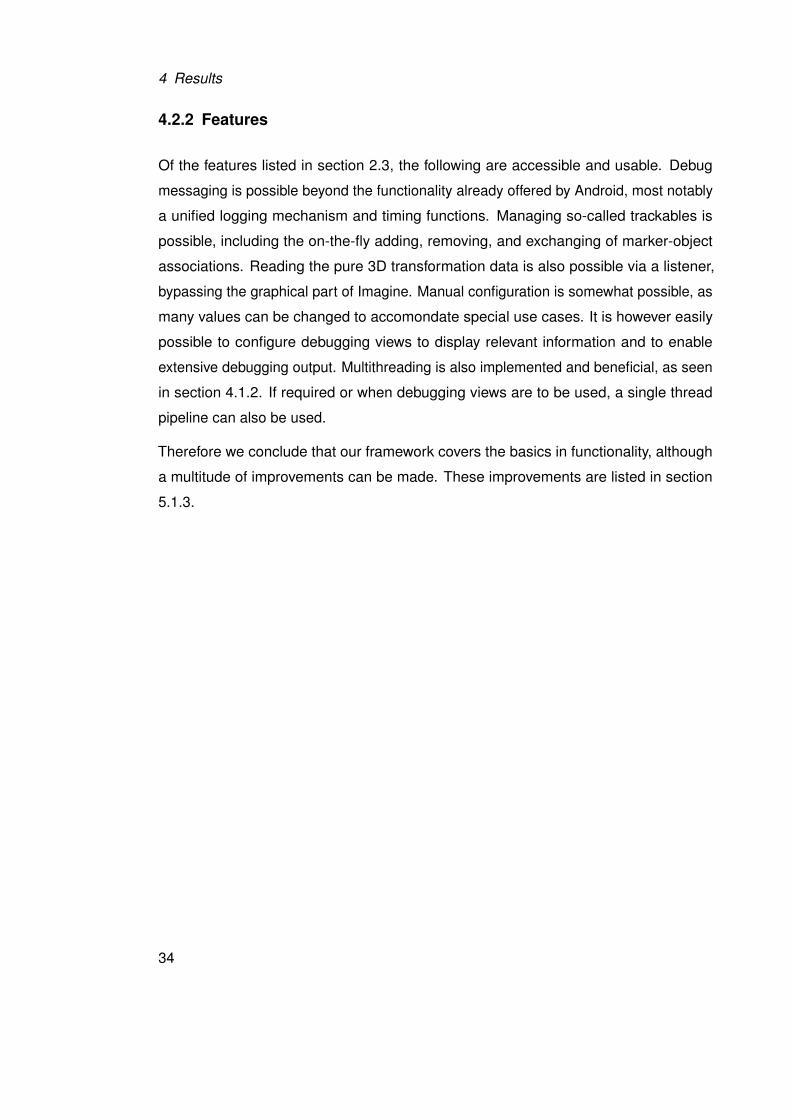
To enable rapid testing and experimenting, we implemented a basic application for
evaluating our framework. It consists of two activities: one for setting parameters and
control values and one for actually running the framework.
Figure 4.3 shows a screenshot of the menu of the application. Here, most values that
are of interest for using Imagine can be set. Most important are the start button on top
and the textfield for adding and removing trackables beneath it. For this application, a
simple model is provided – the user can only change which markers will be tracked.
Figure 4.3: A screenshot of the menu of the application.
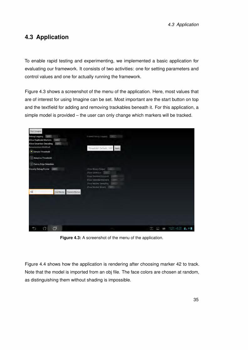
Figure 4.4 shows how the application is rendering after choosing marker 42 to track.
Note that the model is imported from an obj file. The face colors are chosen at random,
as distinguishing them without shading is impossible.
35
4 Results
Figure 4.4: A screenshot of the application rendering the trackable for marker 42.
Figure 4.2 is a screenshot of the application running the framework activity with de-
bugging values activated. These are all the options given below the marker selection
field.
4.4 Comparison to similar Apps
In this section, we will compare Imagine to two other marker-based augmented reality
frameworks for Android. Both are open source projects and can be used freely in
personal projects. Table 4.1 lists the main differences.
Framework FPS Number of markers Maximum parallel markers
Imagine 5 256 256
Aruco 4 1024 unknown
DroidAR unknown 4096 5
Table 4.1: Short table of feature comparison of Imagine, Aruco, and DroidAR.
36
4.4 Comparison to similar Apps
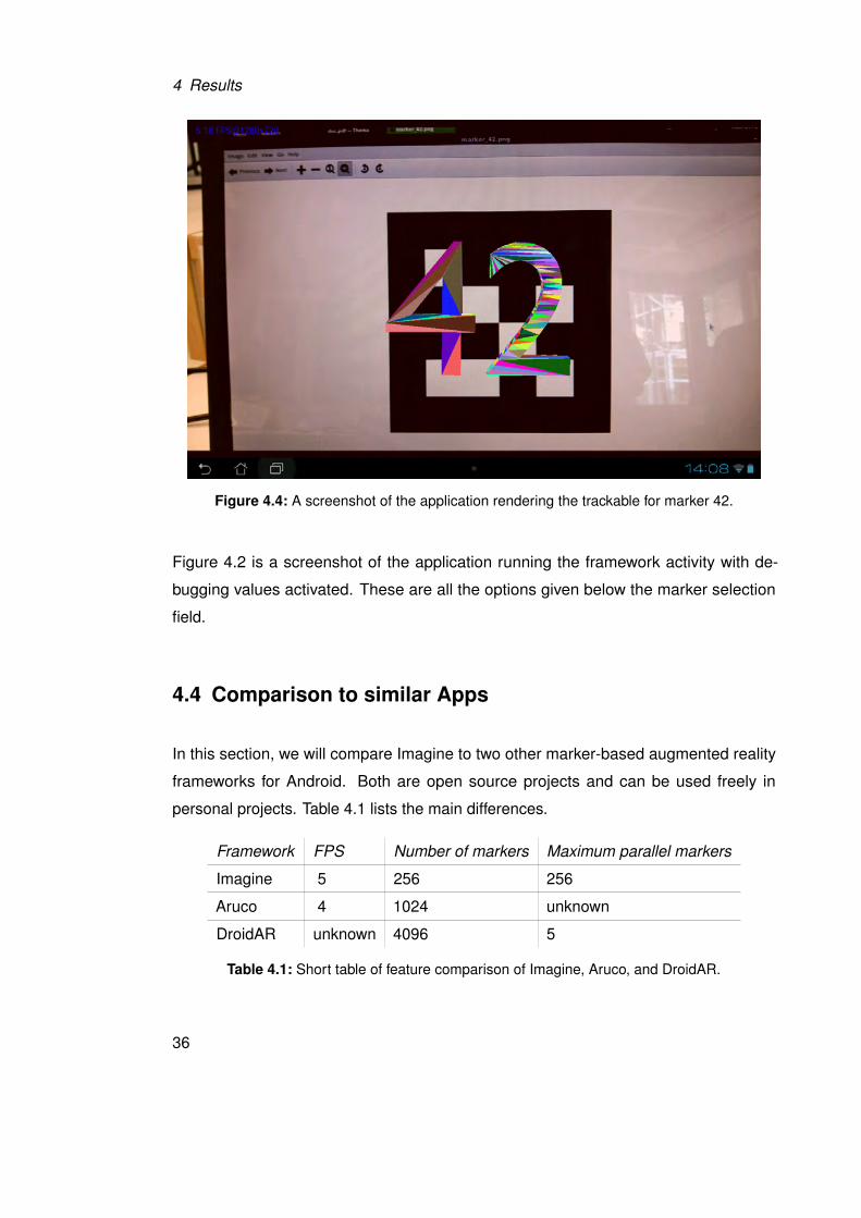
4.4.1 Aruco
Aruco [aru] is a minimal library for Augmented Reality applications based on OpenCV.
Primarily, it is intended for desktop C++ applications, although an Android port and
web-based Javascript port exist. For the purpose of comparing it to our own framework,
we will base the comparison on the Javascript port [jsa] running on the same developer
machine.
Figure 4.5: Screenshot of a basic Aruco application.
The main features of Aruco are simple usage, 1024 markers that can be identified,
and the support of so-called AR boards5. The marker detection algorithm used by
Aruco is the basis for our own work and thus works similarly. The main differences in
implementation are that Aruco does sub pixel accuracy and a higher number of markers.
These are advantages of Aruco over Imagine.
The Javascript port runs at around four frames per second in a mobile web browser.
This is a low difference compared to Imagine, although our framework runs natively. We
believe this due to the fact that while Aruco is based on OpenCV, the Javascript port
can not use the library, and thus re-implements the required features. That removes any
overhead caused by unused features and allows a completely native environment for
data objects, without any significant conversions having to be done, which were one
bottleneck in Imagine. Nonetheless Imagine is a small step faster.5Markers composed of several markers for higher reliability.
37
4 Results
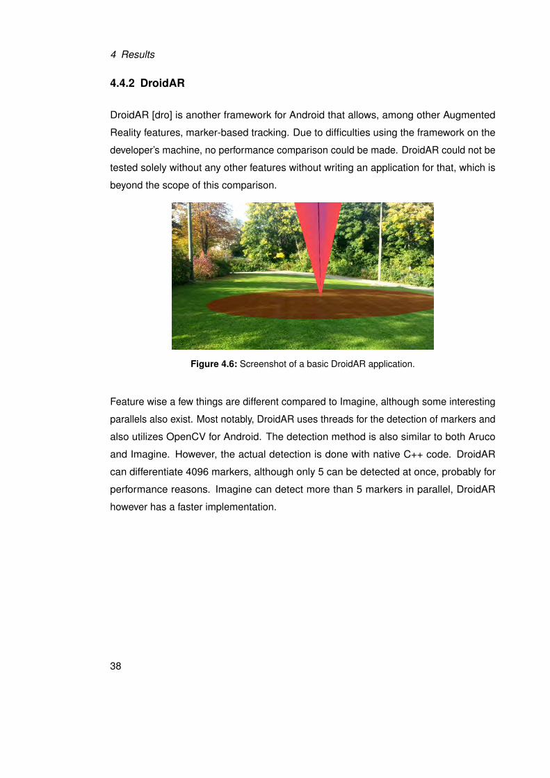
4.4.2 DroidAR
DroidAR [dro] is another framework for Android that allows, among other Augmented
Reality features, marker-based tracking. Due to difficulties using the framework on the
developer’s machine, no performance comparison could be made. DroidAR could not be
tested solely without any other features without writing an application for that, which is
beyond the scope of this comparison.
Figure 4.6: Screenshot of a basic DroidAR application.
Feature wise a few things are different compared to Imagine, although some interesting
parallels also exist. Most notably, DroidAR uses threads for the detection of markers and
also utilizes OpenCV for Android. The detection method is also similar to both Aruco
and Imagine. However, the actual detection is done with native C++ code. DroidAR
can differentiate 4096 markers, although only 5 can be detected at once, probably for
performance reasons. Imagine can detect more than 5 markers in parallel, DroidAR
however has a faster implementation.
38
5Conclusion
Finally we will give a broad overview of the accomplishments of this work, difficulties
encountered, possible improvements, and use cases. We will finish with a broad closing
statement.
The complete final version of the code base for Imagine can be found on Github [gitb].
5.1 Future Possibilities
While basically completely usable, there are many aspects that can still be improved.
These range from performance considerations, porting Imagine to other platforms, to
extending the functionality offered. In this section, we will propose some aspects that
we think could be of interest for future work as they were beyond the time scope of this
project.
39
5 Conclusion
5.1.1 Performance
Concerning the performance of Imagine a lot could still be done, although globally the
performance will remain limited by the capabilities of OpenCV for Android – see also
section 4.1.2. One of the main aspects that could be tried however is writing the main
method that detects markers using OpenCV with native C++ and calling that from the
Java environment with a native call. We did not try that because of two factors: one, a
basic Java framework was the primary goal, and two, developing a Java application for
Android with native code in C++ would have put this work beyond our time frame. It would
also have further divided our attention away from the core functionality, as considerable
time would have had to be spent learning and utilizing the native development kit.
We are also confident that some aspects of the OpenCV code could be optimized even
further, although that might require a more significant analysis with better and robuster
timing features. The performance of the worker threads when using multithreading could
certainly also be improved further, as multithreading is hard to do correctly.
Apart from Imagine, improvements in the runtime environment – Android itself – could
yield further speed gains, although that would most definitely be beyond the scope of
the framework and take a lot of time.
Apart from software aspects various hardware considerations could also lead to better
performance. One would be the increase of the speed at which the camera generates
preview images, allowing OpenCV to grab these faster for further accessing. A higher
count of CPU cores could also serve to increase the speed by running more worker
threads. A faster CPU than the 1.4 GHz Quadcore used here will should also increase
performance.
5.1.2 Features
While Imagine offers a basic rendering system, it lacks a decent rendering system for
production use that can fully utilize the OpenGL ES 2.0 framework. Shading, texturing,
and animation would benefit the use-cases greatly. These features however would be a
project unto itself and was thus left for a future time.
40
5.1 Future Possibilities
Another feature that would make using Imagine easier is implementing either a lookup
model for camera values or offering an internal method for generating them. This would
allow the removal of determining these numbers externally into the framework, further
abstracting away possible hurdles to using it.
To improve resistance against marker occlusion and increase marker detection precision,
support for marker boards such as used by Aruco could also be added. However we
believe that implementation of such a capability would only be feasible once Imagine
has better performance, as the number of markers required for a marker board greatly
decrease the framerate.
5.1.3 Improvements
From an architectural standpoint, the flow of data within the framework could be improved.
Especially the transfer of data to and from the worker threads could surely be solved
better to remove execution blocks. Most notably the fetching of input frames could
be resolved so that the live preview drawn in the background were independent in
speed from the worker threads. This would however require extensive knowledge of
multi-threading, and was thus deemed beyond the scope of this project.
The external application programming interface could be expanded too to allow a better
and more detailed control of the inner workings. Care should be taken to keep the basic
simplicity of using the framework though. Internal states that could be opened to external
control include the resolution of the images, rendering settings, and marker properties.
Internally, Imagine could be expanded to refine corners using subpixel interpolation
when detecting the contours of possible markers. The OpenCV method for subpixel
precision is however expensive in terms of performance. The advantage of subpixel
interpolation would be a better pose estimation, removing sudden jumps and improving
the visual fidelity.
41
5 Conclusion
5.1.4 Extended Possibilities
Speaking on a more general view, some extended possibilities for future work offers
themselves. One of the more interesting ones would be the porting of the framework to
other platforms, most likely for desktop computers first as they offer significantly more
processing power. Higher graphical fidelity and more features for the rendering side
would also become a possibility.
A further possibility would be the harnessing of further OpenCV functionality concerning
the adaptability of the output. This could range from situation aware rendering concerning
the lighting of models to detection of further information from objects found in the scene.
42
5.2 Closing Statement
5.2 Closing Statement
We have shown our results of implementing a Java framework for Android for marker
based detection to be used in Augmented Reality programs. This includes preparatory
work for the framework and the basic application that utilizes it, to the finished results.
The framework, called Imagine, covers the basic required features to be fully functioning,
although various aspects could still be greatly improved and expanded upon.
Apart from the framework, documentation and explanation of its workings have been
created. Documentation is to be found in the Javadoc of the project, also seamlessly
accessible by any modern IDE during active development. This paper highlights the
internal functionality of Imagine and how to access it. Insight into debugging capabilities
and possible areas where difficulties might arise are also highlighted.
We have also shown some possibilities for further work that would significantly expand
the use-cases of our framework. To help with future evaluations we have also done
some basic benchmarks and timed the currently most processing intensive part – the
detection algorithm.
All in all, we are satisfied with the promise of Imagine, although in detail there are many
areas worthy of more development time. We consider the framework to be academically
usable, but would refrain from utilizing it in a production scenario due to low performance
while detecting markers. We believe the code of Imagine however to be an excellent
starting point to learn how to implement Augmented Reality applications as it provides at
the very least a basically functional framework.
43

44
5.2 Closing Statement
Glossary
3D Refers to three dimensional space; mainly to differentiate from two
dimensions
Activity Main component of Android applications; implements required methods for
running on Android
Android Refers to the mobile operating system developed by Google, mainly for ARM
CPUs
Augmented
Reality
Refers to a live, direct view of a physical, real-world environment whose
elements are augmented by computer-generated sensory input[ard]; Often
simply AR
C++ C-based object oriented programming language, primarily general purpose,
although high performance applications on Android can use it
De-warp Refers here to warping an image from its perspective view to a flat view
Entity The user created object used by Imagine to register a marker to track,
complete with 3d model information to be shown when the corresponding
marker is detected. Externally accessible
IDE Stands for integrated development environment; mostly a supportive
program for writing and deploying code
Imagine Name of the project framework
Java Object oriented programming language that is the main language for
programming Android applications
Marker A printed or displayed significant pattern which the system can recognize
through image detection. Used to represent the location of the augmented
space projected by the system
OpenCV Library for computer vision algorithms and methods; OpenCV for Android
therefore refers to the Android port
OpenGL ES Library for hardware accelerated, cross-platform graphics
Trackable The object used by Imagine to combine detected marker information with
data to be used when rendering. Not externally accessible
45

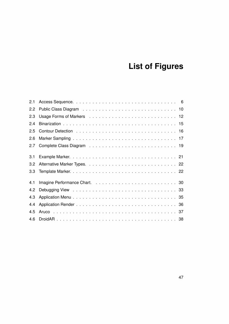
List of Figures
2.1 Access Sequence. . . . . . . . . . . . . . . . . . . . . . . . . . . . . . . . 6
2.2 Public Class Diagram . . . . . . . . . . . . . . . . . . . . . . . . . . . . . 10
2.3 Usage Forms of Markers . . . . . . . . . . . . . . . . . . . . . . . . . . . 12
2.4 Binarization . . . . . . . . . . . . . . . . . . . . . . . . . . . . . . . . . . . 15
2.5 Contour Detection . . . . . . . . . . . . . . . . . . . . . . . . . . . . . . . 16
2.6 Marker Sampling . . . . . . . . . . . . . . . . . . . . . . . . . . . . . . . . 17
2.7 Complete Class Diagram . . . . . . . . . . . . . . . . . . . . . . . . . . . 19
3.1 Example Marker. . . . . . . . . . . . . . . . . . . . . . . . . . . . . . . . . 21
3.2 Alternative Marker Types. . . . . . . . . . . . . . . . . . . . . . . . . . . . 22
3.3 Template Marker. . . . . . . . . . . . . . . . . . . . . . . . . . . . . . . . . 22
4.1 Imagine Performance Chart. . . . . . . . . . . . . . . . . . . . . . . . . . 30
4.2 Debugging View . . . . . . . . . . . . . . . . . . . . . . . . . . . . . . . . 33
4.3 Application Menu . . . . . . . . . . . . . . . . . . . . . . . . . . . . . . . . 35
4.4 Application Render . . . . . . . . . . . . . . . . . . . . . . . . . . . . . . . 36
4.5 Aruco . . . . . . . . . . . . . . . . . . . . . . . . . . . . . . . . . . . . . . 37
4.6 DroidAR . . . . . . . . . . . . . . . . . . . . . . . . . . . . . . . . . . . . . 38
47
List of Tables
2.1 Required Features . . . . . . . . . . . . . . . . . . . . . . . . . . . . . . . 8
2.2 Possible Features . . . . . . . . . . . . . . . . . . . . . . . . . . . . . . . 8
2.3 Difficult Features . . . . . . . . . . . . . . . . . . . . . . . . . . . . . . . . 9
2.4 Application Programming Interface . . . . . . . . . . . . . . . . . . . . . . 11
4.1 Performance Comparison . . . . . . . . . . . . . . . . . . . . . . . . . . . 36
48
Bibliography
[and] Android. http://www.android.com/. Accessed: 01/10/2013.
[ard] Augmented Reality - definition of Augmented Reality, [. . . ]. http://www.
macmillandictionary.com/buzzword/entries/augmented-reality.
html. Accessed: 15/05/2013.
[aru] Aruco for Android | Home. http://aruco-android.vacau.com/. Accessed:
24/08/2013.
[cal] opencv/samples/android/camera-calibration at master · Itseez/opencv.
https://github.com/Itseez/opencv/tree/master/samples/android/
camera-calibration. Accessed: 08/10/2013.
[Can86] John Canny. A computational approach to edge detection. Pattern Analysis and
Machine Intelligence, IEEE Transactions on, (6):679–698, 1986.
[dev] Eee Pad | Transformer Prime | Spec. http://eee.asus.com/en/
transformer-prime/specification/. Accessed: 05/10/2013.
[dia] Apps/Dia - GNOME Wiki! https://wiki.gnome.org/Apps/Dia. Accessed:
05/10/2013.
[doc] Javadoc Tool Home Page. http://www.oracle.com/technetwork/java/
javase/documentation/index-jsp-135444.html. Accessed: 01/10/2013.
[dro] bitstars/droidar. https://github.com/bitstars/droidar. Accessed:
04/10/2013.
[fac] Faculty of Engineering and Computer Science - Universität Ulm. http://www.
uni-ulm.de/en/in/faculty-of-engineering-and-computer-science.
html. Accessed: 01/10/2013.
49
Bibliography
[gita] Git. http://git-scm.com/. Accessed: 05/10/2013.
[gitb] xamino/bachelor_framework_git. https://github.com/xamino/bachelor_
framework_git. Accessed: 14/10/2013.
[GPSR13] Philip Geiger, Rüdiger Pryss, Marc Schickler, and Manfred Reichert. Engineering
an advanced location-based augmented reality engine for smart mobile devices.
Technical Report UIB-2013-09, University of Ulm, Ulm, October 2013.
[Ham50] R.W. Hamming. Error detecting and error correcting codes. 1950.
[ide] IntelliJ IDEA — The Best Java and Polyglot IDE. http://www.jetbrains.com/
idea/. Accessed: 05/10/2013.
[jsa] js-aruco - A JavaScript library for Augmented Reality applications - Google Project
Hosting. https://code.google.com/p/js-aruco/. Accessed: 04/10/2013.
[opea] ANDROID | OpenCV. http://opencv.org/platforms/android.html. Ac-
cessed: 24/04/2013.
[opeb] OpenCV Manager – Android Apps on Google Play. https://play.google.com/
store/apps/details?id=org.opencv.engine. Accessed: 25/09/2013.
[SSP+13] Johannes Schobel, Marc Schickler, Rüdiger Pryss, Hans Nienhaus, and Manfred
Reichert. Using vital sensors in mobile healthcare business applications: Challenges,
examples, lessons learned. In 9th Int’l Conference on Web Information Systems and
Technologies (WEBIST 2013), Special Session on Business Apps, pages 509–518,
May 2013.
[tex] Texmaker (free cross-platform latex editor) . http://www.xm1math.net/
texmaker/. Accessed: 05/10/2013.
[ulm] Homepage - Universität Ulm. http://www.uni-ulm.de/en/homepage.html.
Accessed: 01/10/2013.
[umb] Umbrello Project - Welcome to Umbrello - The UML Modeller. http://umbrello.
kde.org/. Accessed: 05/10/2013.
50
Name: Tamino P.S.M. Hartmann Matriculation number: 722891
Erklärung
Ich erkläre, dass ich die Arbeit selbstständig verfasst und keine anderen als die angegebe-
nen Quellen und Hilfsmittel verwendet habe.
Ulm, den . . . . . . . . . . . . . . . . . . . . . . . . . . . . . . . . . . . . . . . . . . . . . . . . . . . . . . . . . . . . . . . . . . . . . . . . . . . . .
Tamino P.S.M. Hartmann


![State of Augmented Reality, Virtual Reality and Mixed Reality · State of Augmented Reality, Virtual Reality and Mixed Reality [Microsoft Hololen] [Ready Player One] Augmented Reality](https://img.pdfslide.us/doc/110x75/5f82ab6da2d89130b90d78c7/state-of-augmented-reality-virtual-reality-and-mixed-reality-state-of-augmented.jpg)


![theory And Applications Of Marker-based Augmented Reality · 3 Theory and applications of marker-based augmented reality [Markkeriperustaisen lisätyn todellisuuden teoria ja sovellukset]](https://img.pdfslide.us/doc/110x75/5b14736d7f8b9a487c8d243c/theory-and-applications-of-marker-based-augmented-reality-3-theory-and-applications.jpg)