Embed Size (px)
Citation preview
Copyright 2013 IS&T
Proc. IS&T Archiving Conference, 2013
Image Stitching: Exploring Practices, Software and Performance
Don Williams; Image Science Associates; Williamson, NY/US, Peter D. Burns; Burns Digital Imaging; Fairport, NY/US
Abstract The merging or stitching of separately captured portions
(tiles) of an object into a single unified digital image is becoming
increasingly popular in the cultural heritage community. Maps,
negatives, tapestries, and paintings that were once too onerous to
digitize faithfully because of their physical size are now included
in digital collections. These can be digitally sewn together from
component images with several post-processing solutions. In some
cases large robotic systems are accomplishing these tasks.
When such stitched images are viewed without a known
reference image the stitching performance can appear quite
remarkable. What and where are the hidden flaws in these stitched
objects? Are certain content types more prone to stitching errors
than others? Are there analytical tools to detect stitching errors or
are visual assessments sufficient? What operational guidelines and
software options offer the best stitching solutions? And, as is often
the case, do these tools cater to other imaging sectors with quite
different sensitivities than those of cultural heritage institutes.
We explore these questions and offer an assessment of best
current thinking on the pros and cons of different digital stitching
solutions and guidelines on how to make them perform well.
Introduction As the need to faithfully digitize large flat objects (larger than
A0) with sufficient resolution has increased, so too have the
solutions for doing so. A classic and simple solution has been to
physically scale common linear array scanner hardware to match
expected object sizes. The concept is simple: move a large flat
object past an imaging detector head in a precisely timed manner
to capture single lines of image data that are then sequentially
combined to yield a finished image file of a two dimensional
object. While not often thought of as image stitching, this
approach is indeed the most basic and accurate form of stitching:
line after line of image data is combined by the scanner’s hardware
environment to yield a larger ‘stitched’ image in two dimensions.
Some linear array scanners will even move the linear array
side to side over a wide platen area and stitch the sideway image
components together for greater areal coverage. Combining these
image components is accomplished within the scanner’s image
processing pipeline and is invisible to the user. These are examples
of integrated imaging systems, where high level knowledge about
the scanner’s position, performance and movements is available
beforehand. This approach is used to achieve very high stitching
accuracy. In this sense, the image stitching process has near perfect
‘vision.’
Such methods, and intelligence, are used on a grand scale
today using two-dimensional step-and-repeat robotic systems
employing rapid capture devices. These are typically used to
digitize large vertically mounted artwork (typically paintings or
large murals) [1] that is difficult to move, and must be scanned in-
situ. These tend to be highly constrained closed systems, whose
imaging performance parameters (geometric distortion and
vignetting), are calibrated beforehand and compensated for in post-
capture processing. However, the total ownership costs (e.g.,
training, equipment, software, and maintenance) can be high, and
outside the budgets of most institutions.
A more common, economical, approach uses capture devices,
like digital SLR cameras or linear array scanners, with limited
fields of view to capture multiple sub-images that together cover
an entire object of interest. For this community these objects tend
to be large maps, newspapers, tapestries, and even large format
negatives where higher sampling rates (i.e. dpi, ppi) are required.
These environments are distinguished from stitching of large
artwork in several ways.
Less high-level calibration information. Generally speaking,
well-characterized lens data, or resources to reliably measure them,
are simply not available for most users. Having this lens correction
information available with software to exploit it helps greatly in
accurate stitching reconstruction. Lack of these data requires blind
processing, based on general assumptions. This can result in poor
results.
Demanding productivity requirements. Large amounts of time to
manually edit images to remove stitching artifacts are just not
acceptable for most imaging environments. While computational
execution time to stitch images together is acceptable, manual
intervention must be held to a minimum.
Challenging content types and usage. Stitching errors near abrupt
high contrast features with strong rectilinear visual cues, especially
in the midst of large monotonous image regions, can be quite
objectionable. Especially for maps, accurate stitching is critical
because of the spatial geometry requirements. The stitched image
is an object of information, not just a picture meant for casual
viewing.
We concentrate our study and exploration in this paper on this
digitization environment since it is the predominant case for
cultural heritage imaging institutes.
Underlying Software Operations And now I see with eye serene, the very pulse of the machine.
Henry Wordsworth, She was a Phantom of Delight
The basic operations underlying an image stitching operation
include;
1. Identifying approximate relative location of the various
component (tile) images.
2. Identifying corresponding image features in each of the
overlapping regions.
3. Selection of stitching boundaries, margins, for each set of
overlapping regions.
4. Correction for camera distortion or perspective differences,
based on image intensity differences and locations of
corresponding features. This step will often involve
resampling of the image information in regions far from the
stitching boundaries, in order to deliver a continuous-
appearing composite image.
5. Merging (combining) of the image (pixel-value) data at and
near to the stitching boundaries.
As stated above, a good approach for image processing, but
especially operations which involve object identification and
content interpretation, is to supply available a priori information
whenever practical. For our applications this will take the form of;
• Relative location and orientation of component images,
alleviating step 1. Furthermore, if these are related by simple
translation (overlapping tiles at regular intervals), this reduces
the loss of detail in the final image (step 4).
• Known or reduced camera distortion and perspective
differences. This helps with step 4.
• Reduced image intensity differences (due to illumination
variation) between component images. This reduces the
severity of the processing in step 5.
Figure 1, from Ref. 2 shows several of the steps in modern
image stitching software. The example is shown for the stitching of
a neighboring image to a ‘target’ image. The second step shows the
identification of an overlap region, based on several corresponding
features. As seen in the third step, a candidate stitching path is
identified by searching the two images for a low-variation (called
‘minimum error’) path. This is done so as to reduce the visibility of
the stitching boundary in the final composite image. The two sets
of image data are merged (combined) at and near the boundary. In
this case, some features in the target image on the left are replaced
by more uniform regions in the second image. Note that, for this
example, both input component images are assumed corrected
(resampled) for any spatial distortion and differences in sampling
and rotation.
Figure 1: Outline of steps used in current image stitching software (from Ref. 2)
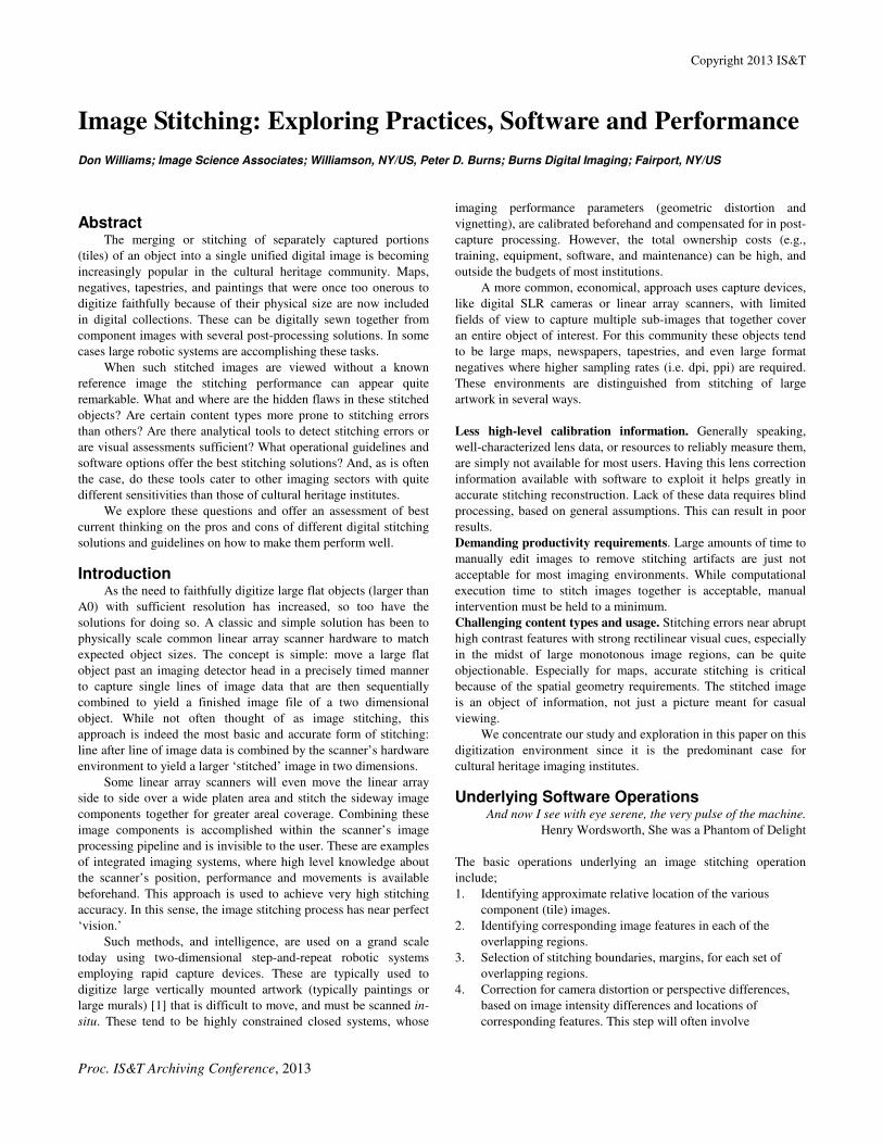
We now describe a simple experiment aided at investigation
the likely imaging performance when image stitching is working
well, with a highly textured scene. As an example of a complex
scene, consider Fig. 2, from a digital camera. This input scene was
then cropped into four overlapping tile images, as indicated by the
rectangles superimposed on the scene. These four sub-images
where then stitched together using Adobe Photoshop software,
which worked well. While displaying the stitched image in the
ordinary way on a computer monitor, the differences between
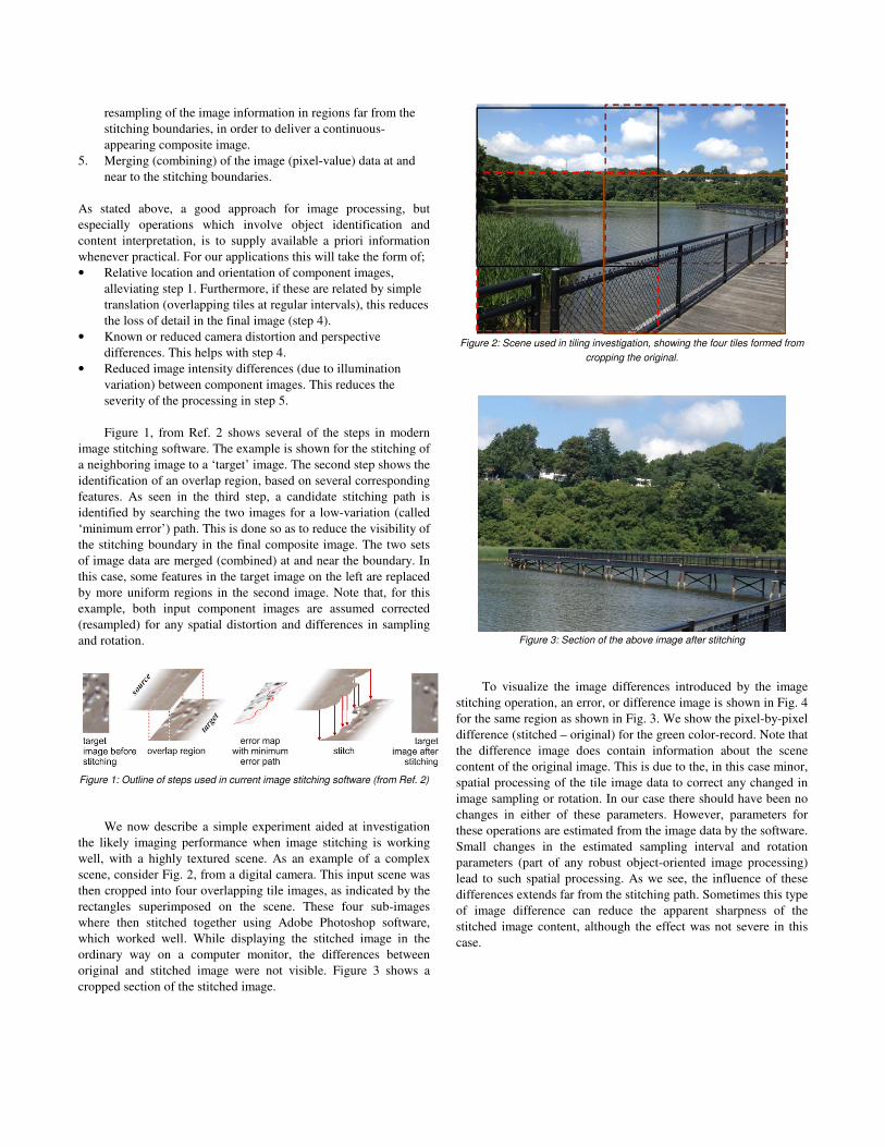
original and stitched image were not visible. Figure 3 shows a
cropped section of the stitched image.
Figure 2: Scene used in tiling investigation, showing the four tiles formed from
cropping the original.
Figure 3: Section of the above image after stitching
To visualize the image differences introduced by the image
stitching operation, an error, or difference image is shown in Fig. 4
for the same region as shown in Fig. 3. We show the pixel-by-pixel
difference (stitched – original) for the green color-record. Note that
the difference image does contain information about the scene
content of the original image. This is due to the, in this case minor,
spatial processing of the tile image data to correct any changed in
image sampling or rotation. In our case there should have been no
changes in either of these parameters. However, parameters for
these operations are estimated from the image data by the software.
Small changes in the estimated sampling interval and rotation
parameters (part of any robust object-oriented image processing)
lead to such spatial processing. As we see, the influence of these
differences extends far from the stitching path. Sometimes this type
of image difference can reduce the apparent sharpness of the
stitched image content, although the effect was not severe in this
case.
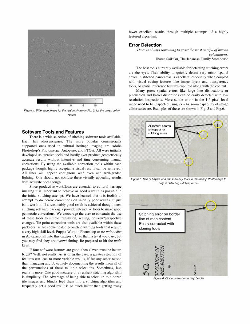
Figure 4: Difference image for the region shown in Fig. 3, for the green color-
record
Software Tools and Features There is a wide selection of stitching software tools available.
Each has idiosyncrasies. The more popular commercially
supported ones used in cultural heritage imaging are Adobe
Photoshop’s Photomerge, Autopano, and PTGui. All were initially
developed as creative tools and hardly ever produce geometrically
accurate results without intensive and time consuming manual
corrections. By using the available correction tools within each
package though, highly acceptable visual results can be achieved.
All lines will appear contiguous with even and well-graded
lighting. One should not confuse these visually appealing results
with accurate ones though.
Since productive workflows are essential to cultural heritage
imaging it is important to achieve as good a result as possible in
the initial stitching attempt. We have learned that it is foolish to
attempt to do heroic corrections on initially poor results. It just
isn’t worth it. If a reasonably good result is achieved though, most
stitching software packages provide interactive tools to make good
geometric corrections. We encourage the user to constrain the use
of these tools to simple translation, scaling, or skew/perspective
changes. Tie-point correction tools are also available within these
packages, as are sophisticated geometric warping tools that require
a very high skill level. Puppet Warp in Photoshop or tie-point edits
in Autopano fall into this category. Give them a try if you dare, but
you may find they are overwhelming. Be prepared to hit the undo
keys.
If four software features are good, then eleven must be better.
Right? Well, not really. As is often the case, a greater selection of
features can lead to more variable results, if for any other reason
than managing and objectively documenting the results from all of
the permutations of these multiple selections. Sometimes, less
really is more. One good measure of a resilient stitching algorithm
is simplicity. The advantage of being able to select up to a dozen
tile images and blindly feed them into a stitching algorithm and
frequently get a good result is so much better than getting many
fewer excellent results through multiple attempts of a highly
featured algorithm.
Error Detection There is always something to upset the most careful of human
calculations.
Iharea Saikaku, The Japanese Family Storehouse
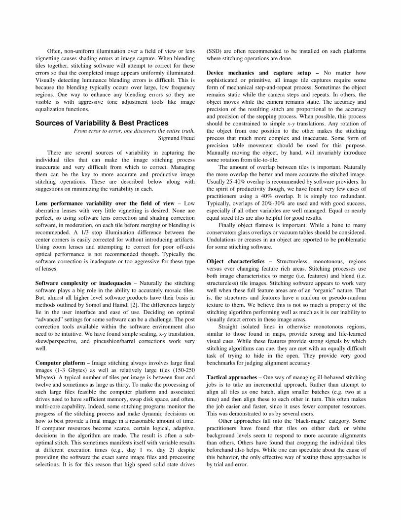
The best tools currently available for detecting stitching errors
are the eyes. Their ability to quickly detect very minor spatial
errors in stitched panoramas is excellent, especially when coupled
with visual cueing features like image layers and transparency
tools, or spatial reference features captured along with the content.
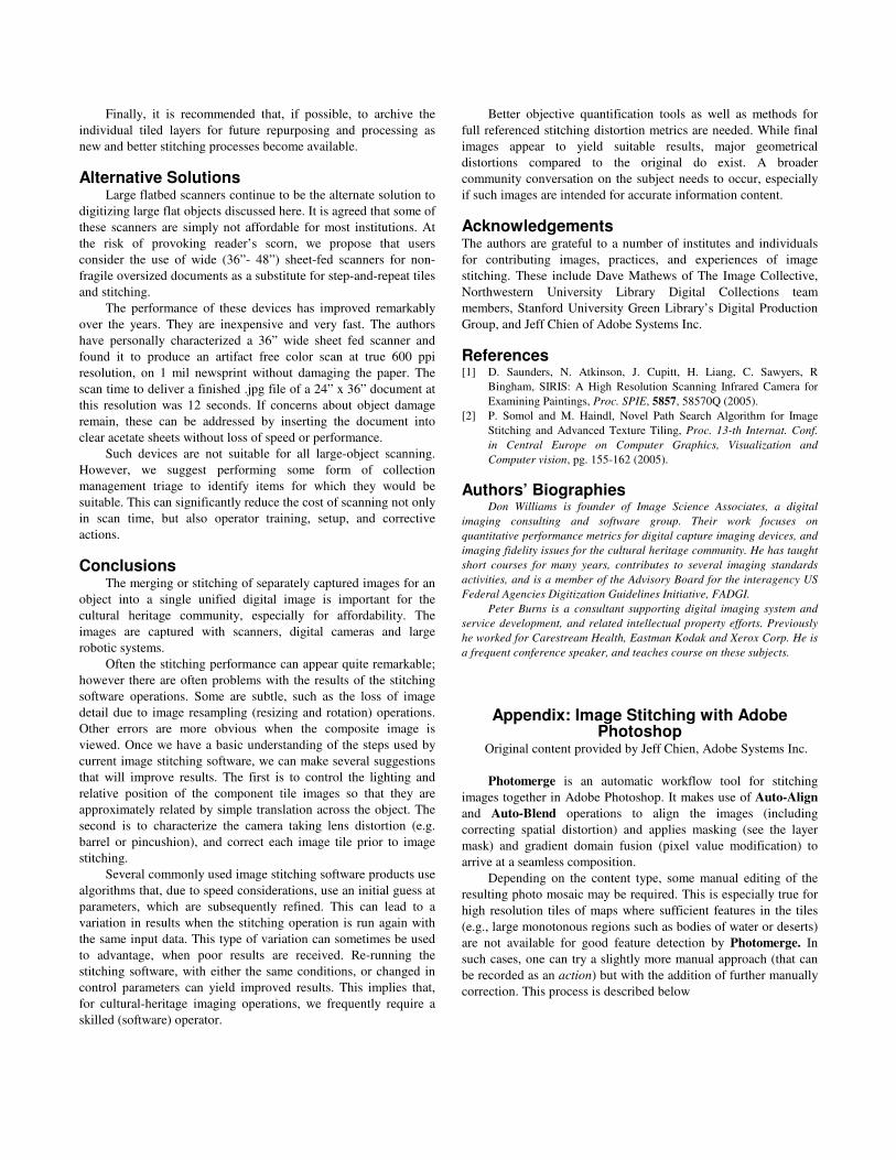
Many gross spatial errors like large line dislocations or
pincushion and barrel distortions can be easily detected with low
resolution inspections. More subtle errors in the 1-5 pixel level
range need to be inspected using 2x - 4x zoom capability of image
editor software. Examples of these are shown in Fig. 5 and Fig.6.
Figure 5: Use of Layers and transparency tools in Photoshop Photomerge to
help in detecting stitching errors
Figure 6: Obvious error on a map border
Often, non-uniform illumination over a field of view or lens
vignetting causes shading errors at image capture. When blending
tiles together, stitching software will attempt to correct for these
errors so that the completed image appears uniformly illuminated.
Visually detecting luminance blending errors is difficult. This is
because the blending typically occurs over large, low frequency
regions. One way to enhance any blending errors so they are
visible is with aggressive tone adjustment tools like image
equalization functions.
Sources of Variability & Best Practices From error to error, one discovers the entire truth.
Sigmund Freud
There are several sources of variability in capturing the
individual tiles that can make the image stitching process
inaccurate and very difficult from which to correct. Managing
them can be the key to more accurate and productive image
stitching operations. These are described below along with
suggestions on minimizing the variability in each.
Lens performance variability over the field of view – Low
aberration lenses with very little vignetting is desired. None are
perfect, so using software lens correction and shading correction
software, in moderation, on each tile before merging or blending is
recommended. A 1/3 stop illumination difference between the
center corners is easily corrected for without introducing artifacts.
Using zoom lenses and attempting to correct for poor off-axis
optical performance is not recommended though. Typically the
software correction is inadequate or too aggressive for these type
of lenses.
Software complexity or inadequacies – Naturally the stitching
software plays a big role in the ability to accurately mosaic tiles.
But, almost all higher level software products have their basis in
methods outlined by Somol and Haindl [2]. The differences largely
lie in the user interface and ease of use. Deciding on optimal
“advanced” settings for some software can be a challenge. The post
correction tools available within the software environment also
need to be intuitive. We have found simple scaling, x-y translation,
skew/perspective, and pincushion/barrel corrections work very
well.
Computer platform – Image stitching always involves large final
images (1-3 Gbytes) as well as relatively large tiles (150-250
Mbytes). A typical number of tiles per image is between four and
twelve and sometimes as large as thirty. To make the processing of
such large files feasible the computer platform and associated
drives need to have sufficient memory, swap disk space, and often,
multi-core capability. Indeed, some stitching programs monitor the
progress of the stitching process and make dynamic decisions on
how to best provide a final image in a reasonable amount of time.
If computer resources become scarce, certain logical, adaptive,
decisions in the algorithm are made. The result is often a sub-
optimal stitch. This sometimes manifests itself with variable results
at different execution times (e.g., day 1 vs. day 2) despite
providing the software the exact same image files and processing
selections. It is for this reason that high speed solid state drives
(SSD) are often recommended to be installed on such platforms
where stitching operations are done.
Device mechanics and capture setup – No matter how
sophisticated or primitive, all image tile captures require some
form of mechanical step-and-repeat process. Sometimes the object
remains static while the camera steps and repeats. In others, the
object moves while the camera remains static. The accuracy and
precision of the resulting stitch are proportional to the accuracy
and precision of the stepping process. When possible, this process
should be constrained to simple x-y translations. Any rotation of
the object from one position to the other makes the stitching
process that much more complex and inaccurate. Some form of
precision table movement should be used for this purpose.
Manually moving the object, by hand, will invariably introduce
some rotation from tile-to-tile.
The amount of overlap between tiles is important. Naturally
the more overlap the better and more accurate the stitched image.
Usually 25-40% overlap is recommended by software providers. In
the spirit of productivity though, we have found very few cases of
practitioners using a 40% overlap. It is simply too redundant.
Typically, overlaps of 20%-30% are used and with good success,
especially if all other variables are well managed. Equal or nearly
equal sized tiles are also helpful for good results.
Finally object flatness is important. While a bane to many
conservators glass overlays or vacuum tables should be considered.
Undulations or creases in an object are reported to be problematic
for some stitching software.
Object characteristics – Structureless, monotonous, regions
versus ever changing feature rich areas. Stitching processes use
both image characteristics to merge (i.e. features) and blend (i.e.
structureless) tile images. Stitching software appears to work very
well when these full feature areas are of an “organic” nature. That
is, the structures and features have a random or pseudo-random
texture to them. We believe this is not so much a property of the
stitching algorithm performing well as much as it is our inability to
visually detect errors in these image areas.
Straight isolated lines in otherwise monotonous regions,
similar to those found in maps, provide strong and life-learned
visual cues. While these features provide strong signals by which
stitching algorithms can cue, they are met with an equally difficult
task of trying to hide in the open. They provide very good
benchmarks for judging alignment accuracy.
Tactical approaches – One way of managing ill-behaved stitching
jobs is to take an incremental approach. Rather than attempt to
align all tiles as one batch, align smaller batches (e.g. two at a
time) and then align these to each other in turn. This often makes
the job easier and faster, since it uses fewer computer resources.
This was demonstrated to us by several users.
Other approaches fall into the ‘black-magic’ category. Some
practitioners have found that tiles on either dark or white
background levels seem to respond to more accurate alignments
than others. Others have found that cropping the individual tiles
beforehand also helps. While one can speculate about the cause of
this behavior, the only effective way of testing these approaches is
by trial and error.
Finally, it is recommended that, if possible, to archive the
individual tiled layers for future repurposing and processing as
new and better stitching processes become available.
Alternative Solutions Large flatbed scanners continue to be the alternate solution to
digitizing large flat objects discussed here. It is agreed that some of
these scanners are simply not affordable for most institutions. At
the risk of provoking reader’s scorn, we propose that users
consider the use of wide (36”- 48”) sheet-fed scanners for non-
fragile oversized documents as a substitute for step-and-repeat tiles
and stitching.
The performance of these devices has improved remarkably
over the years. They are inexpensive and very fast. The authors
have personally characterized a 36” wide sheet fed scanner and
found it to produce an artifact free color scan at true 600 ppi
resolution, on 1 mil newsprint without damaging the paper. The
scan time to deliver a finished .jpg file of a 24” x 36” document at
this resolution was 12 seconds. If concerns about object damage
remain, these can be addressed by inserting the document into
clear acetate sheets without loss of speed or performance.
Such devices are not suitable for all large-object scanning.
However, we suggest performing some form of collection
management triage to identify items for which they would be
suitable. This can significantly reduce the cost of scanning not only
in scan time, but also operator training, setup, and corrective
actions.
Conclusions The merging or stitching of separately captured images for an
object into a single unified digital image is important for the
cultural heritage community, especially for affordability. The
images are captured with scanners, digital cameras and large
robotic systems.
Often the stitching performance can appear quite remarkable;
however there are often problems with the results of the stitching
software operations. Some are subtle, such as the loss of image
detail due to image resampling (resizing and rotation) operations.
Other errors are more obvious when the composite image is
viewed. Once we have a basic understanding of the steps used by
current image stitching software, we can make several suggestions
that will improve results. The first is to control the lighting and
relative position of the component tile images so that they are
approximately related by simple translation across the object. The
second is to characterize the camera taking lens distortion (e.g.
barrel or pincushion), and correct each image tile prior to image
stitching.
Several commonly used image stitching software products use
algorithms that, due to speed considerations, use an initial guess at
parameters, which are subsequently refined. This can lead to a
variation in results when the stitching operation is run again with
the same input data. This type of variation can sometimes be used
to advantage, when poor results are received. Re-running the
stitching software, with either the same conditions, or changed in
control parameters can yield improved results. This implies that,
for cultural-heritage imaging operations, we frequently require a
skilled (software) operator.
Better objective quantification tools as well as methods for
full referenced stitching distortion metrics are needed. While final
images appear to yield suitable results, major geometrical
distortions compared to the original do exist. A broader
community conversation on the subject needs to occur, especially
if such images are intended for accurate information content.
Acknowledgements The authors are grateful to a number of institutes and individuals
for contributing images, practices, and experiences of image
stitching. These include Dave Mathews of The Image Collective,
Northwestern University Library Digital Collections team
members, Stanford University Green Library’s Digital Production
Group, and Jeff Chien of Adobe Systems Inc.
References [1] D. Saunders, N. Atkinson, J. Cupitt, H. Liang, C. Sawyers, R
Bingham, SIRIS: A High Resolution Scanning Infrared Camera for
Examining Paintings, Proc. SPIE, 5857, 58570Q (2005).
[2] P. Somol and M. Haindl, Novel Path Search Algorithm for Image
Stitching and Advanced Texture Tiling, Proc. 13-th Internat. Conf.
in Central Europe on Computer Graphics, Visualization and
Computer vision, pg. 155-162 (2005).
Authors’ Biographies Don Williams is founder of Image Science Associates, a digital
imaging consulting and software group. Their work focuses on
quantitative performance metrics for digital capture imaging devices, and
imaging fidelity issues for the cultural heritage community. He has taught
short courses for many years, contributes to several imaging standards
activities, and is a member of the Advisory Board for the interagency US
Federal Agencies Digitization Guidelines Initiative, FADGI.
Peter Burns is a consultant supporting digital imaging system and
service development, and related intellectual property efforts. Previously
he worked for Carestream Health, Eastman Kodak and Xerox Corp. He is
a frequent conference speaker, and teaches course on these subjects.
Appendix: Image Stitching with Adobe Photoshop
Original content provided by Jeff Chien, Adobe Systems Inc.
Photomerge is an automatic workflow tool for stitching
images together in Adobe Photoshop. It makes use of Auto-Align
and Auto-Blend operations to align the images (including
correcting spatial distortion) and applies masking (see the layer
mask) and gradient domain fusion (pixel value modification) to
arrive at a seamless composition.
Depending on the content type, some manual editing of the
resulting photo mosaic may be required. This is especially true for
high resolution tiles of maps where sufficient features in the tiles
(e.g., large monotonous regions such as bodies of water or deserts)
are not available for good feature detection by Photomerge. In
such cases, one can try a slightly more manual approach (that can
be recorded as an action) but with the addition of further manually
correction. This process is described below
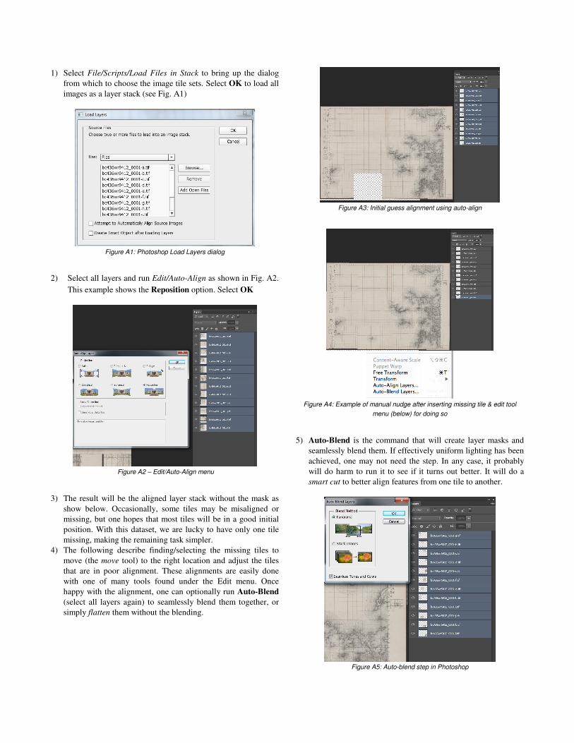
1) Select File/Scripts/Load Files in Stack to bring up the dialog
from which to choose the image tile sets. Select OK to load all
images as a layer stack (see Fig. A1)
Figure A1: Photoshop Load Layers dialog
2) Select all layers and run Edit/Auto-Align as shown in Fig. A2.
This example shows the Reposition option. Select OK
Figure A2 – Edit/Auto-Align menu
3) The result will be the aligned layer stack without the mask as
show below. Occasionally, some tiles may be misaligned or
missing, but one hopes that most tiles will be in a good initial
position. With this dataset, we are lucky to have only one tile
missing, making the remaining task simpler.
4) The following describe finding/selecting the missing tiles to
move (the move tool) to the right location and adjust the tiles
that are in poor alignment. These alignments are easily done
with one of many tools found under the Edit menu. Once
happy with the alignment, one can optionally run Auto-Blend
(select all layers again) to seamlessly blend them together, or
simply flatten them without the blending.
Figure A3: Initial guess alignment using auto-align
Figure A4: Example of manual nudge after inserting missing tile & edit tool
menu (below) for doing so
5) Auto-Blend is the command that will create layer masks and
seamlessly blend them. If effectively uniform lighting has been
achieved, one may not need the step. In any case, it probably
will do harm to run it to see if it turns out better. It will do a
smart cut to better align features from one tile to another.
Figure A5: Auto-blend step in Photoshop