Embed Size (px)
Citation preview
I
IL
AD-753 327
GAS-11RESS EQE 0. ,., N G0,,NADING CF M ULTI ' INERGUN BARRELS
Roy E. Beal, et al
HIT Research Institute
& Prepared for:
Army Weapons Command
July 1972
DISTRIBUTED BY:
I National Technical information ServiceU. S. DEPARTMENT OF COMMERCE
5285 Port Royal Road, Springfield Va. 22151

AD0
SWERR-TR-72 '2
GAS-PRESSURE BONDING OF MULTILAYER GUN BARRELS
TECHNICAL REPORT -
July 1972
Rep)rodv~t• •
NATIONAL TECHNICALINFORMAHION SERVICE
RESEARCH DIRECTORATE
WEAPONS LABORATORY AT ROCK ISLAND
RESEARCH, DEVELOPMENT AND ENGINEERING DIRECTORATE
U. S. ARMY WEAPONS COMMANDA f
I I Approved for public release, distribution urnlimited.
DISPOSITION INSTRUCTIONS:
Destroy this report when it is no longer needed. Donot return it to the originator.
DISCLAIMER:
The findings of this report are not to be construed asan official Department of the Army position unless so designatedby other authorized documents.
/
L ~SW't'r( ,/'
NtI . ,-'.,. 1•
I l. /,,. .I,-D I
VOW -
Is

UnclassifiedSecurit Classification
DOCUMENT CONTROL DATA. R & D(Securlty clasaslticaton of tiltle, body of absltrac and Indexind anno#tbion must be entered when the o*erall report Is €lassilledj
I ON•OINATING ACTIVITY (Corporate autlor) 0I. REPORT SECURITY CLASSIFICATIONlIT Research Institute Unclassified10 West 34th Street 21.GROUP
Chicago, Illinois 606163 REPORT TITLE
GAS-PRESSURE BONDING OF MULTILAYER GUN BARRELS (U)
4 OESCRIPTIVE NOTES ("ypje ofr rpot eand inclustve dates)
S AU THORIS) (Ptrlt name, middle iniltl, leat name)
Roy E. BealThomas Watmough
I.REPORT °ATE 7.e ,OTAL NO OF PAGES NG* OF mars
July 1972Se. CONTRACT OR GRANT NO. e, ORIGlNA1OR'S REPORT NUtr3ERII)
DAAFOI-71-C-0021b. PROJECT NO I ITRI-B61 08-4
C. Ob. OTHER REPORT NOIS) (Any oth.er numbere telf may be eatllnedtitle reprt)AMS Code 4932.06. 7017d. SWERR-TR-72-42
I DISTRIDUTION STATEMENT
Approved for public release, distribution unlimited.
11 SUPPLEMENTARY NOTE)S 12 SPONSORING MILITARY ACTIVITYU. S. Army Weapons Command[Research & Engineering DirectorateIRock Island, lllinniq 6172nl
I, A program was undertaken by the Research Directorate, Weapons LaboratoryP, at Rock Island, to determine the feasibility of using gas pressureV. tech, iques fur production of lined, prerifled gun barrels. Pressure
containers constructed from short-length tubular steel sections ma-chined to gun barrel bore dimensions were used in this experiment.From the results of the tests performed with low-yleld strength ma-terials (copper and Monel), a suitable profile replication was notattained on the rifle surface. On the basis of test data obtained,
iforming a ri f jin profiIe and U^ '5 I.4130 steel were found to be impractical with gas pressure bondingtechniques. (U) (Beal, R. E. and Watmough, T.
DDPLCX DO'.17 FORMY14710. 1JN4,WIHSD D F"00N~ 1 4 7 3 1 Aoo. ,N 6. .,, .R IC . U n c l a s s i f ie d
SeCurity CtSllfit`8tion
UnclassifiedSec.m!' V!asification
14 LINK A LINK 0 LINK CWI WROI ,, k I I1L. J W
1. Joining
2. Welding
3. Solid-state Bonding
4. Jsostatic (Hot) Pressure Bonding
5. Diffusion Bonding
Unclassified
Security Clessiftiotwnpm

Au
RESEARCH DIRECTORATE
WEAPONS LABORATORY AT ROCK ISLAND
RESEARCH, DEVELOPMENT AND ENGINELRING DIRECTORATE
U S ARMY WEAPONS COMMAND
TECHNICAL REPORT
SWERR-TR-72-42
GAS-PRESSURE BONDING OF MUL T ILAYER GUN BARRELS
july 1972
DAArOl-71-C-O021 AMS Code 4932.06 7017
Approved for public release, distribution unl,mited
I!

ABSTRACT
A program was undertaken by the Research Directorate,Weapons Laboratory at Rock Island, to determine the feasi-bility of using gas pressure techniques for production oflined, prerifled gun barrels. Pressure containers con-structed from short-length tubular steel sections machinedto gun barrel bore dimensions were used in this experiment.From the results of the tests performed with low-yieldstrength materials (copper and Monel), a suitable profilereplication was not attained on the rifle surface. On thebasis of test data obtained, forming a rifling profile andbonding with a tantalum alloy on AISI 4130 steel were foundto be impractical with gas pressure bonding techniques.
I
ii

FOREWORD
This report was prepared by R, B. Beal, J. Dolega,E. Chester, and T. Watmough of the I.I.T. Research Institute,Chicago, Illinois, in compliance with Contract DAAFOl-71-C-0021 under the technical supervision of the ResearchDirectorate, Weapons Laboratory at Rock Island, U. S. ArmyWeapons Command, with R. B. Miclot as project engineer.
The work was authorized as part of the ManufacturingMethods and Technology Program of the U. S. Army MaterielCommand which is administered by the U. S. Army ProductionEquipment Agency.
V
I i

CONTENTS
Paae
Title Page
Abstract ii
Foreword ii
Table of Contents iv
List of Illustrations vi
1. Introduction
2 Materials and Processes 2
2.1 Manufacture of Short-Length Tubular 3Sections2 1 ,I Gun Barrel Material 3
2, 1 2 Fabrication of Pressure Capsules 32 1 3 Welding of Pressure Capsules 9
2.2 Gas Pressurization Facility
2 3 Liners 132 3.1 Materials 132 3 2 Fabrication 15
2 3 3 Attachment 15
2 4 Welding Fabricated Sleeve to Pressure 17
2.5 Vacuum Between Liner and Vessel 171 3. Test Proced 20..
iv
CONTENTS
Page
4. Test Results 23
5. An Examination of a G. E. Preliminary Test 32
6. Discussion 36
7. Predicted Liner Profiles 38
8. Conclusions 45
9. Recommendations 45
Distribution 46
DD Form 1473 (Document Control Data R&U) 49
rX
}v
I.
ILLUSTRATIONS
Figure Page
1 Proposed Pressure Capsule 4
2 Angles Used on Rifled Projections 5
3 End Cap of Pressure Capsule with View of 6Gas Entry PortI 4 Rifled Pr'ojections on the Bore of the 7Tubular Section
5 Machined SAE 4130 Pressure Capsule 8Prepared for Welding
6 End Cap Weld Detail 10
7 Aloy Steel 4130 Pressure Vessel Ready 11for Test
8 Ma-eosection of Main Pressure Vessel Weld 12
9 General View of Gas Pressure Pump and 14Furnace
10 Welding Jig for Liner FaLb-ication 16
11 Design Detail of Mild Steel Insert 18
12 Monel Liner with Vacuum Tube Attached 19Ready for Insertion into Pressure Vessel
13 Liner Collapse due to Leak Between Liner 21and Vessel
14 ShortLength Tubular Sections with Sections 22Removci for Examination of Liners
vi
ILLUSTRATIONS
Figure
15 Liner of 0.020-Inch-Thick Monel over Pro- 24jection after 10,000 psi at Room Temperature
16 Liner of 0.020-Inch-Thick Monel over Pro- 25jection after 10,000 psi at O100 0 F
17 Liner of 0.01-Inch-Thick Monel with View of 26Good Contact except for Projection Edge,75' Angle
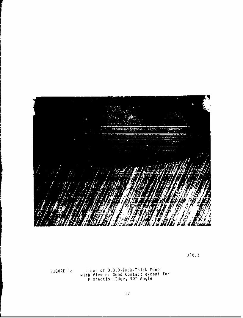
18 Liner of 0.OiO-Inch-Thick Monel with View of 27Good Contact except for Projection Edge,90* Angle
19 Liner o7 O.0O0-Inch-Thick Monel with View of 28Good Contact except for Region of ProjectionEdge, 450 Angle
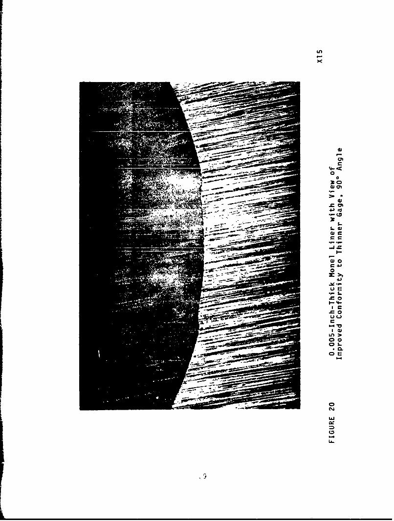
20 0.005-Inch-Thick Monel Liner with View of 29Imprnved Conformity to Thinner Gage, 90° Angle
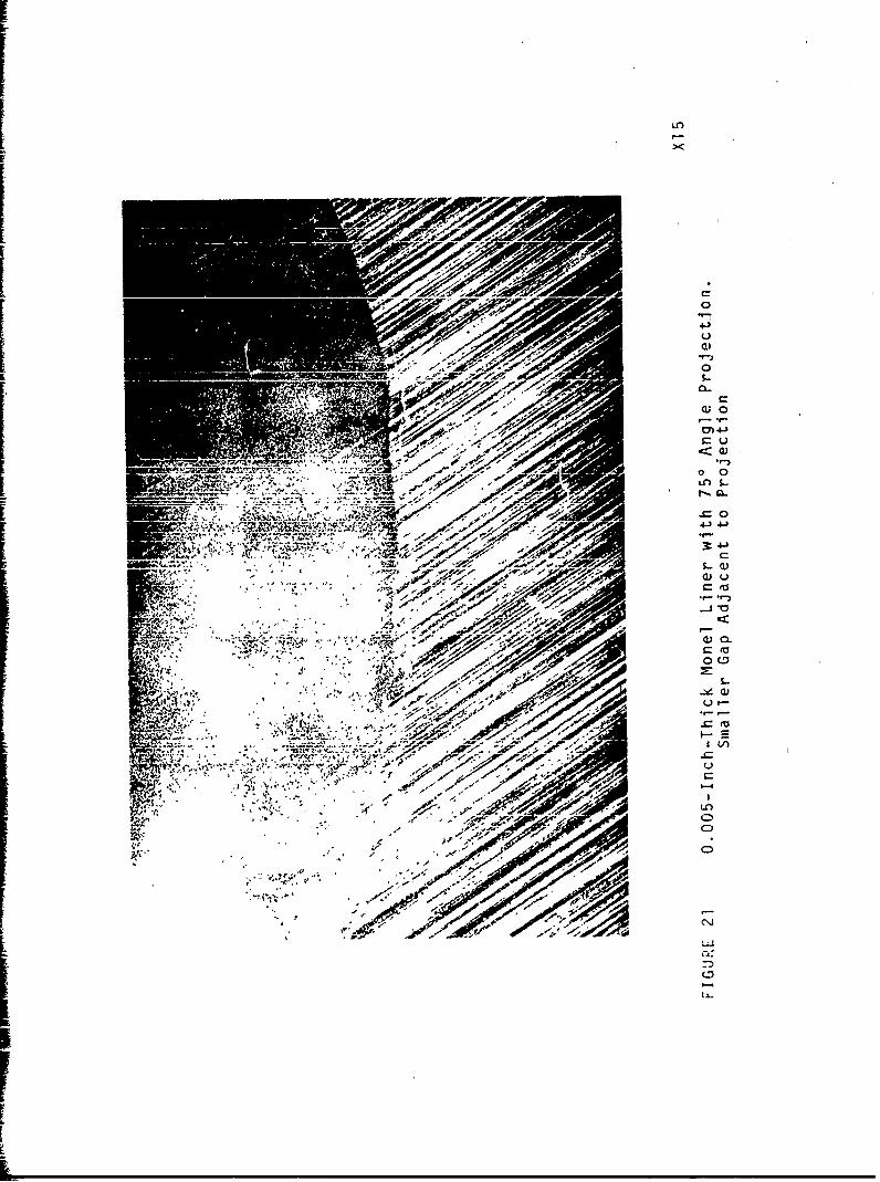
21 0.005-Inch-Thick Monel Liner with 750 Angle 30Projection: Smaller Gap Adjacent to Projection
22 Monel Liner, 0,005-Inch-Thick with 45' Angle, 31Gap at Edge of Projection
23 Monel 0O005-Inch-Thick Cross Section with 33
View of (a) Sprirgback during Preparation,(b) Projection and Liner as Pressurized
24 Copper Liner U.O]0-Inch-Thick after Pressur- 34ization at 5000 psi
25 Tantalum Alloy Liner Gas-Pressure Bonded to 354130 Steel
vIIrvi

LLUSTRATIONS
Figure Page
26 Free Liner Length at Bonding Temperature with 39901 Projection Angle and 10,000 psi Pressure
27 Projection Height Necessary for 450 Angle 40Conformity to Various Liner Thicknesses andto 10,000 psi Pressure
128 Predicted Parameter Relationships for Maximum 42Yield Strength Requirement for 45' Conformity
29 Influence of Projection Angle on Conformity 43to Projection Height of 0.050-Inch and toVarious Liner Thicknesses
30 Influence of Projection Angle on Conformity 44
to Projection Height of 0.005-Inch
viii

1. INTRODUCTION
A rapid-fire weapon generates tremendous quantitiesof heat, and the high velocity of projectiles and pro-pellant debris moving through the barrel cause rapid ero-sion of the bore. High strength low alloy steels used ingun barrel manufacture do not offer adequate erosion resis-tance. A suitable method by which to overcome the erosionproblems of alloy steels is that of lining the bore withan erosion resistant material. The liner material must becapable of integral bonding with the barrel to produce acomposite material.
A coextrusion method has been developed by the ResearchDirectorate with a refractory alloy liner bonded during thecoextrusion process. Although the coextrusion method issatisfactory for bonding refractory alloy liners to steelgun tubes, the subsequent swaging operation can only impartconstant twist rifling to the lined tubes. The lining ofgain twist rifled gun barrels is a problem area that mustbe resolved. Explosive forming techniques have been pre-viously used for this lamination process, but the effortshave been unsuccessful.
The possibility of producing a prerifled steel gunbarrel to which a suitable liner is subsequently att'achedhas been considered. Two main criteria are involved in thesuccessful application of this approach: first, the re-producing of prerifled profile on the inner surface of theattached liner and, secondly, satisfactory bonding of theliner to the barrel. In this program, the feasibility hasbeen explored with respect to reproducing, on the liner,the prerifled profile machined into the barrel.
With short length tubular sections of SAE 4130 steel,lined sections have been produced at temperatures up to1000OF with a gas pressure bonding technique. In this
W, apprnach: the need of a specially designed pressure vesselwith internal heating facilities was avoided, and thefeasibility of the technique was studied in a relativelyinexpensive manner. Three different liner materials wereincluded in the program that made possible an examinationol several yield strengths and their influence on linerapplication without the use of unduly high test tempera-tures. Less importance was placed on bonding parameters,
The objective of this program was to produce a gain
twist rifled gun barrel with a refractory alloy liner forsuperior erosion resisLance. The barrel material must be
I ...
capable of withstanding high temperature loading; therefore,a design requirement of 40,000 psi yield strength at 1500*Fhas been stipulated The line' material is selected fromprevious erosion work and is the tantalum alloy Ta-lOW.
This material has a yield strength of 90,000 psi at 16000F.The outer element or gun barrel will be prerifled. Theliner must be attached and take the shape of the barrel.A rifling projection 3/16-inch-wide and 0.005-inch highwas required by design The lining attachment process ormethod must provide for an efficient metallurgical bondbetween the liner and the barrel or, at least, facilitatesubsequent bonding without destruction of the profile in-tegrity. Also the new processing met od au t-e r i y A, = , o 1 ,tIIh d h u l d r e s u l t4 i n
some cost savings in production.
2 MATERIALS AND PROCESSES
Wi 01 this d s-p -eSsure bonding process, t ,1s at highpressure and elevated temperature is used to fabricatemetallic or ceramic materials The process has been used
to promote bonds between similar and dissimilar metals,ceramics, and cermet materials Advantages include thecapacity to fabricate brittle materials and materials ofwidely differing properties Gas-press,,re bonding alsooffers uniform chemical, physical, and mechanical propertieswithout cast structures incurred with normal fusion weldingprocesses Thus, gas bonding could possibly meet the strin-gent requirements of the metallurgical and joining techniquefo- gun barrels prov'ded the geometric factors are satisfied.
In the gas-pressure bonding process, the components tobe bonded aee fabrcated or machined to final size, cleaned,and assembled into an expendable container or edge-weldedto produce a pressure-tight evacuated envelope The assep-
bled componen;'s are heated to an elevated temperature in anautoclave containing an ,nert gas at a high pressu.r Thwisostatic pressure is unifoemly transmitted, and all mating•Uy'dLf de 1,L d itu 1.uitact aldong the desi" ed surraceeC A n + r% V h e " a f: , . I n C , ý + Z s .4 C a e .a , In n I u n d e r p o e s s u r e za 'I
pera for a sufficient length of time to permit solid-
state bonding between the components The only deformationoccurring is that necessary to bring the parts into contact
bond interfaces can be eliminated *n compatible metal systems.
Cold-wall resistance-heated autoclaves operating atvery h~gh pressures, with test limits indicated by vesseldesign and furnace requirements, have been developed. Forth's program, however, a short-length tubular section ofsteel was considered the most economical pressure container.
Bonds are actually produced by solid-state diffusionthrough coalescence or welding contacting surfaces and areusually performed near the bulk yield strength and 0.4 ofthe absolute melting temperature (T,) of the material. Sub-stantial process temperature reductions are possible by useof a relatively new concept of reaction layer diffusionbonding in which an interlayer of low-melting material isallowed to become liquid and, subsequently to diffuse into
the matrices of the materials to be joined. Material com-patibility is necessary in both adaptations of the process.No attempts at bond examination or parameter optimizationwere made in this study. Effort was focused entirely onthe reproduction of the rifled profile.
2.1 Manufacture of Short-Lenqth Tubular Sections
2.1.1 Gun Barrel Material
Alloy steel SAE 4130 was selected as the outer elementmaterial since the properties of this material at room andelevated temperatures meet the required design criteria.Tests in the program were performed up to lO00F. SAE 4130is relatively weldable so that pressure vessels may be fab-ricated from it. The material was purchased in the normal-ized and tempered condition.
2.1.2 Fabrication of Pressure Capsules
The outer element was designed as a pressure vessel inaccordance with ASME Code Section VIII. A nominal bore di-mension of 1-inch diameter and a pressure capacity of 10,000psi at 1000°F were required. The vessel was also designedto accommodate apDrnximately a 3-inch length of liner fortests. Dimensions of the vessels are given in Figure 1,with details of the pressure entry point and positions ofthe rifled projectiorib.
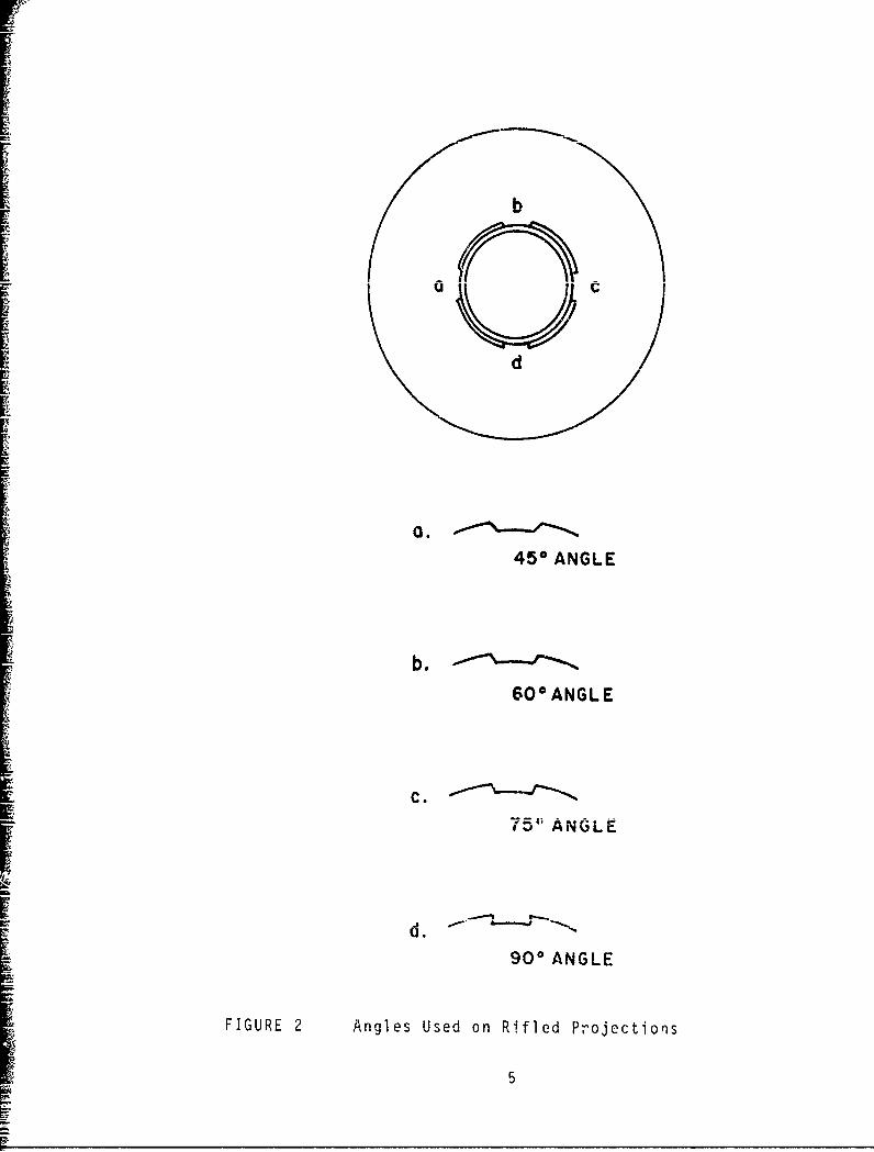
The alloy steel SAE 4130 was drilled and broached, asshown in Figure 2 A special broach was manufactured toaccurately produce the required rifled surface. Four pro-jection angles of 90 , 75', 60', and 45' were broached.Weld preDarations were subsequently machined on all sDeci-mens and end caps produced.
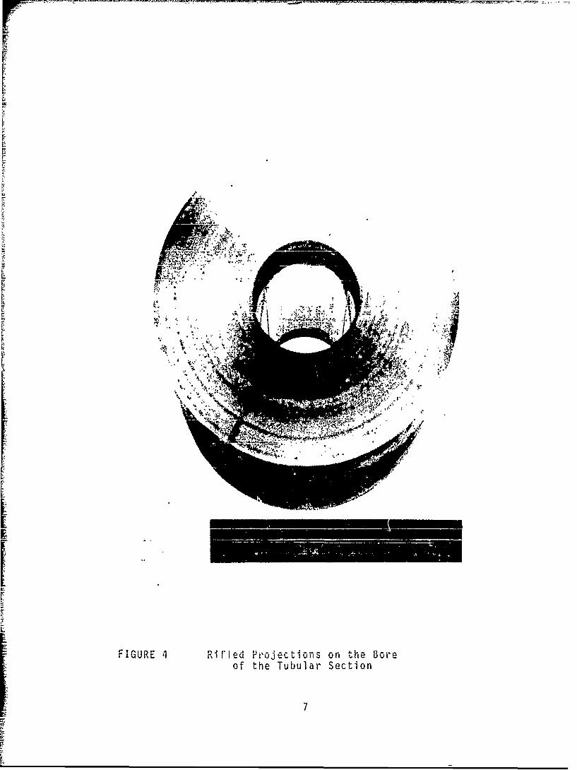
One pressure-capsule end cap with a gas entry port inthe center is shown in Figure 3. A machined and broachedsection is shown in Figure 4. Barrel thickness is ]-inch,and two broached projections can be seen on the intprnalsurface. A completely machined pressure vessel ready forthe main welding operation is shown in Figure 5.
3

RifledProjections
//" Liner
i ,// •_ 'Element
1 0
F" "
00\
7i\ir
I •r End Ca-
FIGURE I Proposed Pressure Capsule
.A1~LN
uy
d
45 ANGLE
600ANGLE
• C.75" ANGLE
90' ANGLE
FIGURE 2 Angles Used on Rifled Projections
5

A .l". *-
Itr
-FIGURE 3 En d C P~ ut ~rC; C a pSLl ewi ~Lh V iev of Gas Entry Port
6
V V
A-)
FIGURE 4 Rifl*1ed Projections on the Boreof the Tubular Section
7

rr
r
I I
F
FIGURE 5 Machined SAE 4130 Pressure CapsulePrepared for Welding
8

2. .l3 Welding Pressure Capsules
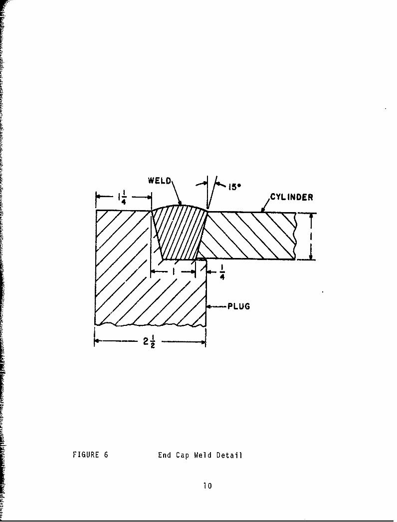
A pressure vessel was initially produced without anyliner to validate welding procedure and design performance.Welding of the end caps to the main body was carried outby use of manual metallic arc process. Weld preparationdetail given in Figure 6 was selected from ASME-approvedpressure'vessel preparations for end closures, A weldpreheat of 6000F was applied. Weld root runs were exe-cuted with Hobart Rocket LH 818 CM 1/8-inch diameter elec-trodes. Other runs were produced with Arcos ChromendIMA E8018-B21, 5/32-inch diameter, 1-1/4 per cent Cr-l/2per cent Mo electrodes. These electrodes are designed toproduce matching mechanical properties with vessel material.
All welding was performed with electrodes at DC posi-tive with a Miller direct-current power source. No mechani-cal tests were made on the main vessel weldments. A com-pleted pressure vessel is shown in Figure 7. A post-weldheat treatment was carried out on the vessel at 1150OF for1 hour at temperature. After pressure testing, a sectionwas removed from the weld for macroscopic examination andhardness determinations, Macroscopic examination revealeda sound weld-deposit as shown in Figure 8. Some small slaginclusions and pores were noted in the weld, and care wasexercised to keep these defects at a minimum. Hardnessdeterminations in the weld and heat-affected zone yieldeda maximum heat-affected zone hardness of Z60-400 HV.,0 , whichwas considered satisfactory, and a weld hardness of 225HVýý. The pressure cell was, therefore, proved for pressureapplication up to 10,000 psi
2 2 Gas Pressurizat'on Facility
An air-dr¾yen gas booster compressor was used to pro-vide the neces,•ry vessel pressurization. The compressorwas capable of a 20,000 psi maximum output at 1000 psi gasinput. A tyiple-head ,ersion was used to apply a relativelyluw drive inlet presaure on the at- 1 lne of 80 psig Th1eunit is a HASKEL Model AG-233-c, capable of delivering 1.7scfm of fully pressured gas at a gas supply pressure of
1000 psi. Argon was used as the pressure medium suppliedfrom a normal tank cvlinder at 600 psi. Satisfactory oper-a-ion of the pressure facility to 10,000 psi was possiblewith this assembly.
A high-pressure gas circuit was designed to include apressure gage monitor with a result regulator and an in-tegral safety valve This arrangement provided good controlover the maximum gas outlet pressure. The outlet gas pressure
9
F
WELD
CYLINDER
FIGURE 6 End Cap Weld Detail
10

4.)cnI-a)
F.
S.-
0
[7
4-
-oa)
a)U)U)
U)S.-a)
1-a)U)
0.
0
1�
LiccC/)a)a)
4.)
0
F cCI-
Li
'-.4
(D
Li�
Ii

t w
J, T;4-,
0~
0~
4-
121
LL
that has been preselected can be sensed by the result regu-lator. The air supply to the pump can be shut off to ensurethe safest operation prouLdure. Variations in the inlet orair pressure drive system, then, do not affect the testpressure applied. Pressure settings are infinitely adjust-able tothe capability of the system.
The gas pressure booster system is capable of reachingpressures of 10,000 psi in approximately one minute and of
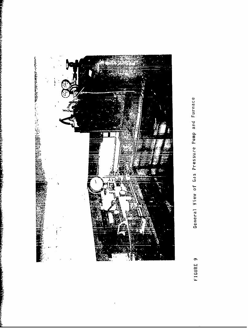
L performing satisfactorily throughout the program. The gasbooster system, furnace, and gas supply are shown in Figure9.
L2.3 Liners
A limitation of the experimental approach was the maxi-mum test temperature of l0001F. At this temperature, re-fractory Ta-lOW alloy still has a very high yield strengthwhich, over a projection, would allow insignificant deforma-tion. since metal deformation over the projection is thoughtto be controlled by the yield strength at the test tempera-ture, much lower-strength materials were selected to approxi-mate elevated temperature deformation of the tantalum alloy.In this manner, a range of material yield strengths would bepossible to test and the feasibility of the concept beingstudied could be determined. The capacity of the projectionto withstand imposed loads during processing is also impor-
tant The gun barrel mateIal has approximately 40,000 psiyield strength and 70,000 psi tensile strength. Liner ma-terials with yield strengths of much less than, approximatelyequivalent to, and higher than the strength of the projec-tions on the gun barrel material were selected,
2.3 1 Liner Materials
Originally, the liner material was to be purchased intubuLiar form in diameters and thicknesses required for theprogram These uhbes were comimer, ia 1 av unva labl e., so pur-chase of strip and manufacture of tube or insert from thestrip forms was necessary,
Annealed copper was purchased with a yield strength of10,000 psi and tensile strength of 32,000 psi at room tem-perature in the tnree thicknesses selected: O.005-inch,0.010-inch, and 0.020-inch Monel was selected as the in-termediate strength material This material has a yieldstrength of 25,000 psi to 45,000 psi, dependent upon itscondition, and a tensile strength in the range of 75,000 psito 85,000 psi. Only 0.020-inch thick material was available.
13
VIZ.-
ilaa
rE - Fls.-( PI
__ (A
CD
\ w

F,The 0.010-inch and 0.005-inch thicknesses were produced bycold-rolling and annealing the as-received alloy. Finally,Ta-lOW refractory material was obtained, the only materialreadily available being 0.005-inch thickness. Typical yieldstrengths of the tantalum alloy are 150,000 psi at roomtemperature and 90,000 psi at 1600°F. This alloy is thechoice material for the liners to be used in actual gunbarrels.
2.3.2 Liner Fabrication
Work commenced on the copper liners, but efforts werepostponed to a later part of the program because of diffi-culties in fabrication of thin-wall copper tubes. Subse-quently, satisfactory copper-lined specimens were producedand are discussed in later sections. Most of the effortpresented here was focused on fabrication of Monel tubes inthe three thicknesses.
A small melt-down lip was needed to weld the longi-tudinal tube joint. A weld jig was devised to hold the thinmaterial in the required position and to provide the necessarygas protection on the reverse side of the joint. The finaljig design is shown in Figure 10. The jig comprises a ma-chined bar, slightly less in diameter than that of the re-quired tube, with a copper tube insert, flattened to accom-
modate the materia.l to be welded and slotted for allowanceof argon backing gas to purge the joint area, The hold-downclamps were designed to give slightly eccentric movementupon clamping so that the material can be gripped firmlyadjacent to the weld. The same jig was used for all thick-nesses to be joined,
Welds were prepared with a Linde needle-arc welderwith an argon-helium mixture. Excellent welds were producedin Monel in all thicknesses. Because the cylinders wererolled and welded, a 0.030-inch total clearance had to begiven between the liner and the inside of the vessel, Thus,the material had to expand 0.030-inch to reach the vesselwall during test, The Ta-lOW refractory alloy welds wereto be made in a backfilled inert gas chamber.
2 3.3 Liner Attachment
Fabrication or attachment of the liner to the innerwall was a difficult task. The method proposed initiallyof simply welding the liner material to the vessel wall wasimpractical. Heat inputs required to melt the vessel ma-terial were too high for the liner, and satisfactory weldscould not be made
15

0
4-)
LU
'4-
C)
uv 4_

IIA relatively large mild steel insert was used for welds
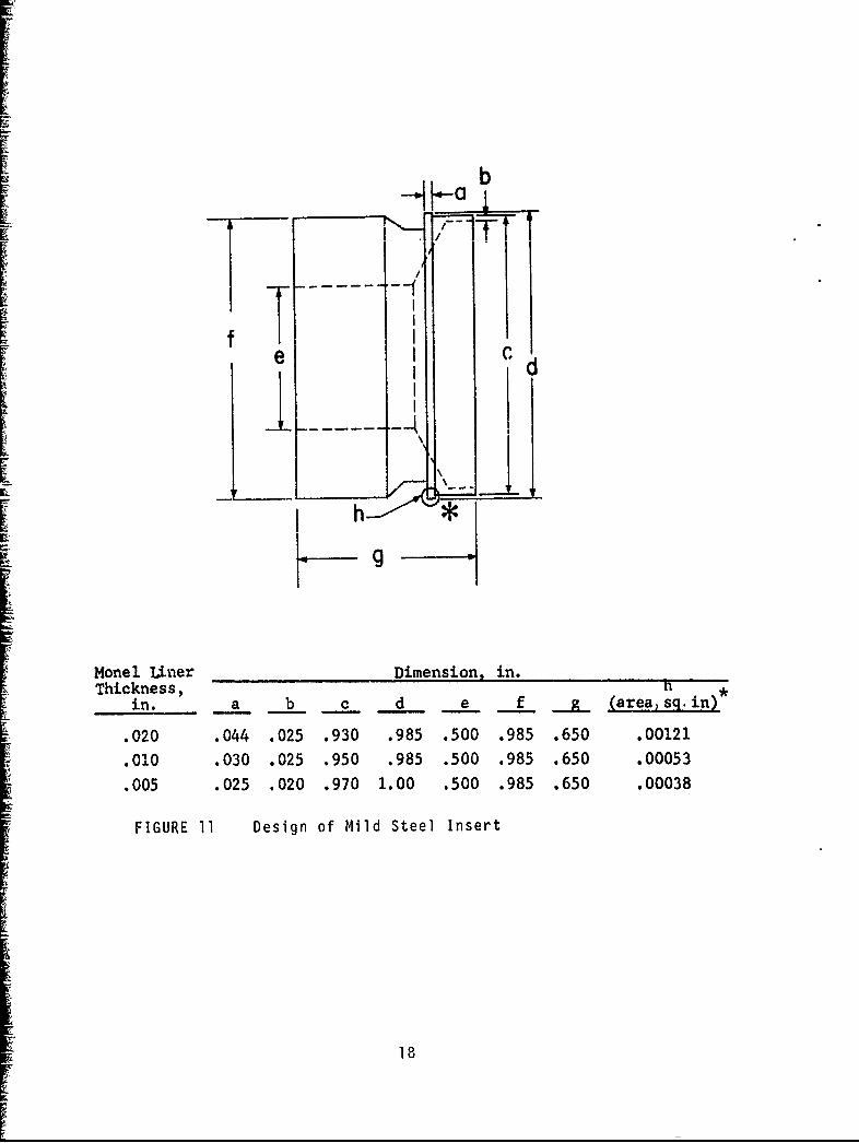
to the vessel wall. The insert was suitably machined toform a projection that could be melted at a rate comparableto the liner. Several attempts were made at insert designbefore a satisfactory item was produced. Details of theinserts are given in Figure il Three sizes of insertsare necessary to produce good welds. The projection "h"was melted down with the edge of the tubular liner to formthe inner sleeve. A fabricated inner sleeve comprising the
[ liner with one insert at each end is presented as Figure 12.The vacuum liner brazed into position for evacuation of theenvelope between the liner and barrel before test can beseen. The vacuum system was modified later. Excellent weldjoints were produced with the method by use of the plasmaneedle-arc welder and nickel alloy filler wire. Metallo-graphic examination confirmed the sound weld procedure.
Welding copper liners by this method was unsuccessful.The copper liner had to be brazed to the insert by a torch-brazing technique and silver-bearing braze alloy. Thisapproach worked well, although some concern was necessarysince weldments had to be produced adjacent to the brazeand remelting of the braze alloy could occur.
2.4 Welding Fabricated Sleeve to Pressure Vessel
The large mild steel insert facilitated the joining ofsleeve to the main pressure vessel The vessels were heatedto 600:F to prevent under'bead cracking, and the insert waswelded with a pure nickel filler rod and the gas tungstenarc process. Some minor crater cracking was encounteredbecause of joint restraint, but this was eiiminated by use-of a current downslope technique at the end of the weld.Metallographic examination of the fillet weld revealed asound weld deposit with no evidence of cracking in the mainpressure container,
2.5 Vacuum Between Liner and Vessel
Vacuum test procedures were instituted at each stageof vessel fabrication. Stage one comprised a vacuum teston butt-welded liner cylinders. A second test was madeafter the liners had been fabricated to the insert. Athird vacuum test was imposed after the brazing of vacuumtubes in position. Finally, a test was performed after thefabricated liners were welded to the main pressure vessel.The samples must be capable of pulling a vacuum of lessthan 1 micron at each stage, with a negligible leak rate.
17
I-
b
Monel ener Dimension, in.
Thickness, *
in. a b c d e f g. (areasq.in)
.020 .044 .025 .930 .985 .500 .985 .650 .00121
.010 .030 .025 .950 .985 .500 .985 .650 .00053
.005 .025 .020 .970 1.00 .500 .985 .650 .00038
FIGURE 11 Design of Mild Steel Insert
18

Ea
CC
u #A
k
_•-o
= I-
uw4.)
E 04-)
0
LLI.
ce
19
V_
Even low-leak rates were not allowable since the pressurecell had to be sealed off at the next stage, and the vacuumcondition maintained between liner and pressure vessel wallwhile the remaining part of the fabrication procedure wascompleted.
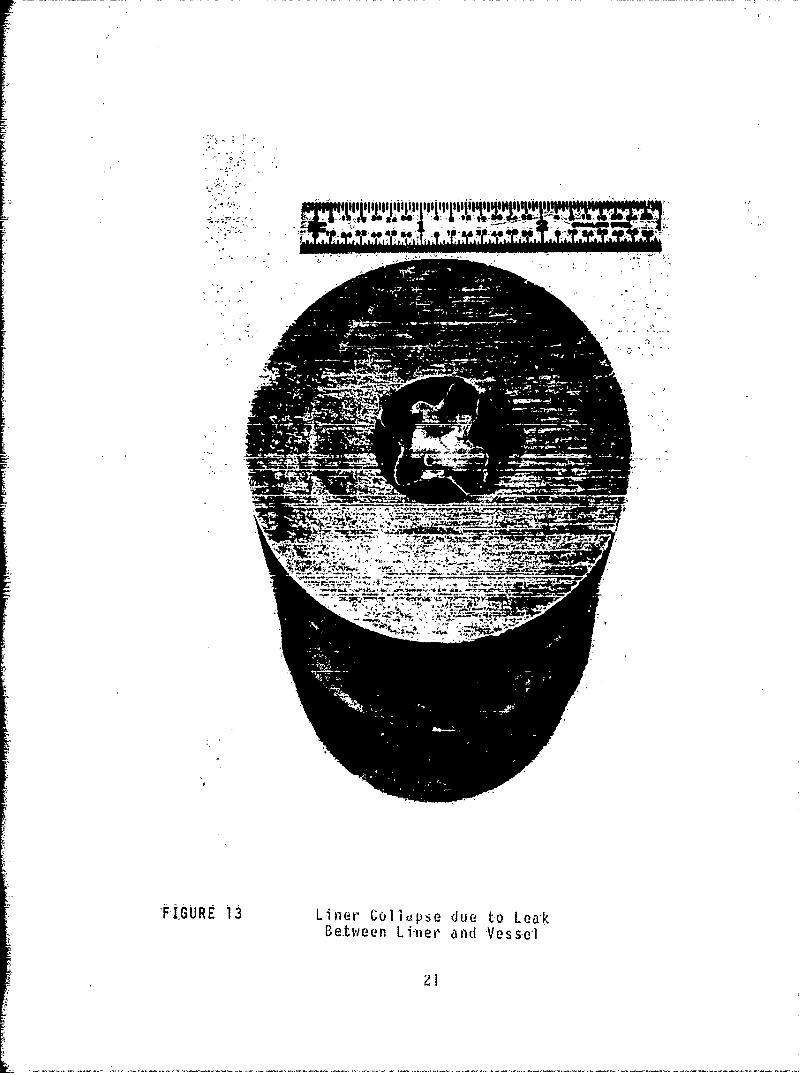
The vacuum sealing-approach was inadequate since theuse of this approach did not provide allowance for outgassingof parts at elevated temperatures nor was the use proved tobe 100 per cent effective. An example of a test in whichthe vacuum between the liner and the vessel failed is shownin Figure 13. In this case, pressurization and expansionof the liner caused a small leak in one of the weldments.Gradually, the pressure behind the liner must have equal-ized. On release of the internal pressure, the liner thencollapsed since the trapped gas could not escape quicklyenough.
Subsequently, similar vacuum test procedures werecarried out in the early stages. Instead of a vacuum lineattached to the liner, a small hole was drilled in thepressure vessel wall located at the insert, and a permanentvacuum line was attached to the outside of the pressure ves-sel. A vacuum could then be continuously pumped throughoutthe experimental cycle, and very small leaks and outgassingcould be accommodated without any problems.
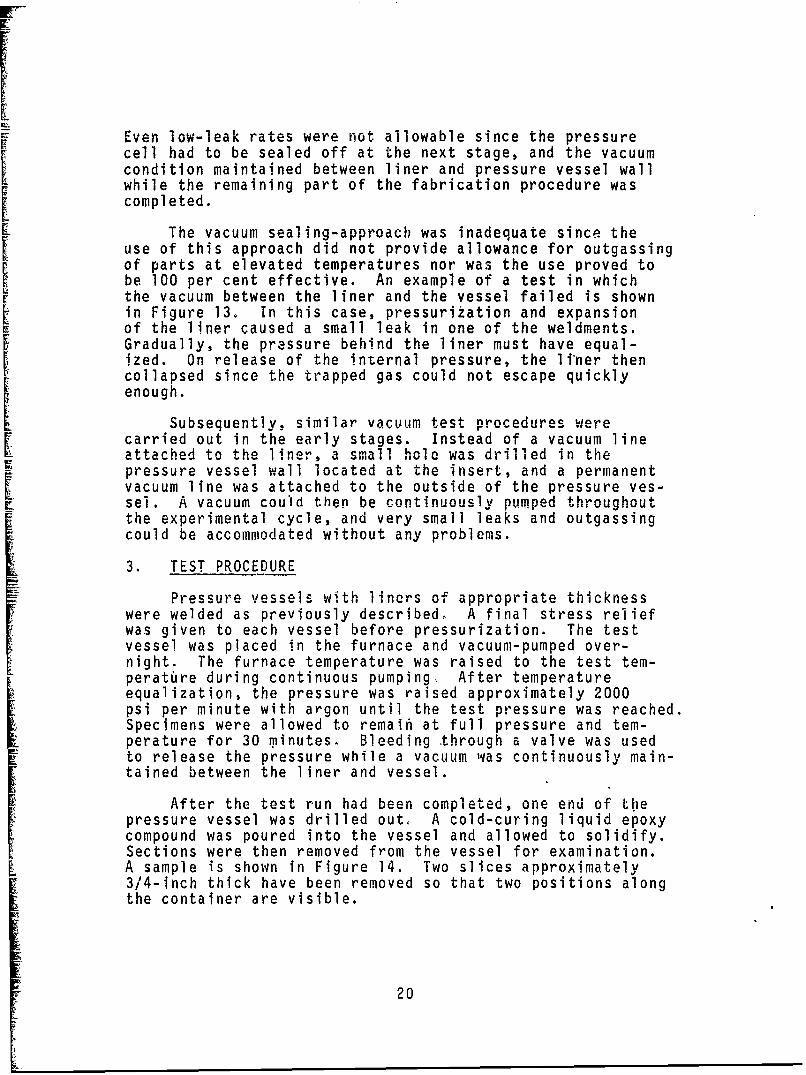
3. TEST PROCEDURE
Pressure vessels with liners of appropriate thicknesswere welded as previously described, A final stress reliefwas given to each vessel before pressurization. The testvessel was placed in the furnace and vacuum-pumped over-night. The furnace temperature was raised to the test tem-perature during continuous pumping, After temperatureequalization, the pressure was raised approximately 2000psi per minute with argon until the test pressure was reached.Specimens were allowed to remaih at full pressure and tem-perature for 30 minutes. Bleeding through a valve was usedto release the pressure while a vacuum was continuously main-tained between the liner and vessel.
After the test run had been completed, one end of thepressure vessel was drilled out, A cold-curing liquid epoxycompound was poured into the vessel and allowed to solidify.Sections were then removed from the vessel for examination.A sample is shown in Figure 14. Two slices approximately3/4-inch thick have been removed so that two positions alongthe container are visible.
20
"TIT
4 4_
FIGURE 13Liner Ccfliopse due to Lea~kBetween Lfiter and Vessel
L1

0rr
I) -]
LL
LL
i22
4. TEST RESULTS
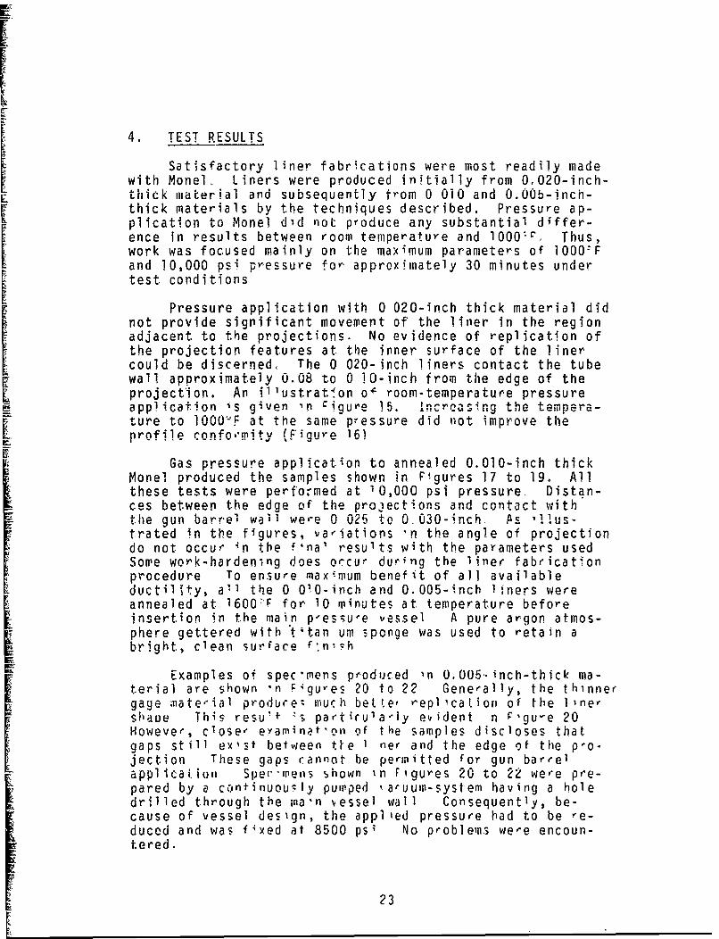
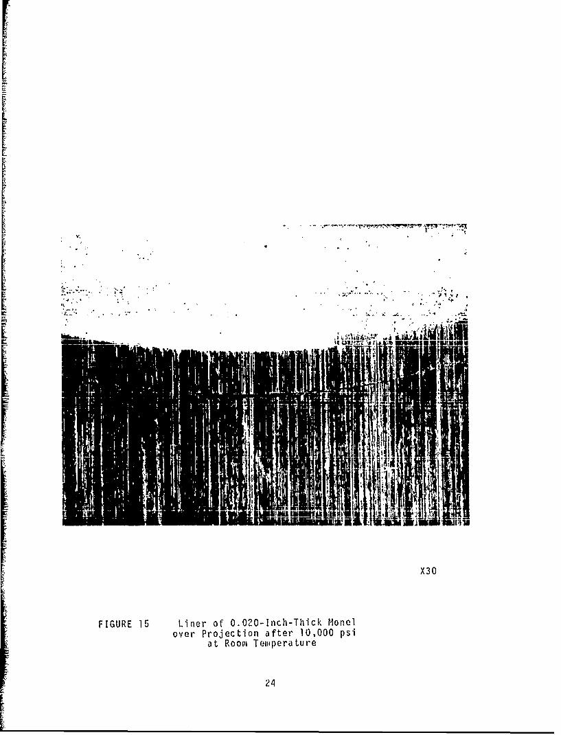
Satisfactory liner fabrications were most readily madewith Monel, Liners were produced initially from 0,020-inch-thick material and subsequently from 0 010 and 0.OOb-inch-thick materials by the techniques described. Pressure ap-plication to Monel did not produce any substantial differ-ence in results between room temperature and 1000'. Thus,work was focused mainly on the maximum parameters of 1000-Fand O,000 psi pressure for approximately 30 minutes undertest conditions
Pressure apphication with 0 020-inch thick material didnot provide significant movement of the liner in the regionadjacent to the projections. No evidence of replication ofthe projection features at the inner surface of the linercould be discerned, The 0 020-inch liners contact the tubewall approximately 0.08 to 0 10-inch from the edge of theprojection. An i 1 1ustrat.on o" room-temperature pressureapplication is given in CigUre 15. Increasing the tempera-ture to iO00(F at the same pressure did not improve theprofile confo,'mity (Figure 16)
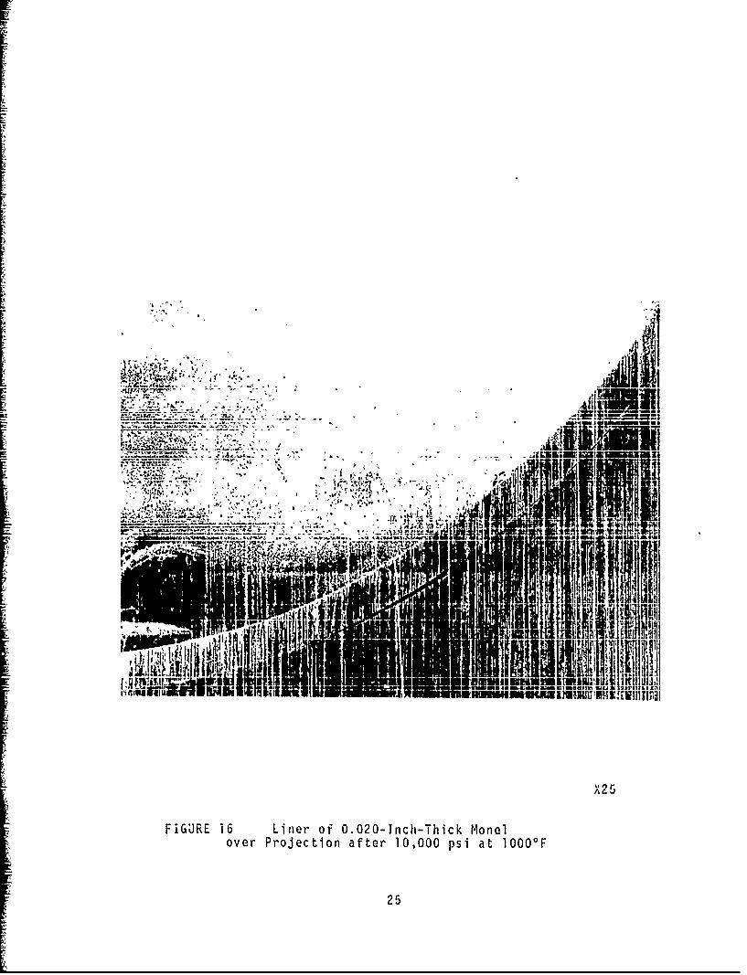
Gas pressure application to annealed 0.010-inch thickMonel produced the samples shown in Figures 17 to 19. Allthese tests were perfo~med at 10,000 psi pressure. Distan-ces between the edge of the projections and contact withthe gun barrel wall were 0 025 to 0.030-inch. As 11lus-trated in the figures, variations 'n the angle of projectiondo not occur in the f•na' results with the parameters usedSome work-hardening does occur during the liner fabricationprocedure To ensure maximum benefit. of all availableductility, a"1 th.e 0 010-inch and 0.005-inch 1 iners wereannealed at 1600-F for 10 minutes at temperature beforeinsertion in the main pessu'e uessel A pure argon atmos-phere gettered with "ttan um sponge was used to retain abright, clean surface f-nl•h
Examples of spec mens poduced in O.005. inch-thick ma-terial are shown n Figu-es 20 to 22 Generally, the thinnergage onate.-ial produre; much betIe, replication of the 1ine,shaue This resu' t `3 partiru'a~ly evident n Fgu-e 20However, close, eyamninet'on of the samples discloses thatgaps still exist between týe I ner and the edge of the po-jection These gaps cannot be peranitted for gun barrelapplica ion Sper"mens shown in Figures 20 to 22 were pre-pared by a continuoucly pumrped ka-uum-systemn having a holedrilled through the na'n vessel wall Consequently, be-cause of vessel design, the applied pressure had to be re-duced and was fixed at 8500 psi No problems were encoun-tered.
23
X30
FIGURE 15 Liner of O.020-1nch-Thick M~onelover Projection after 10,000 psi
at Room Tem~perature
24
M
Iug
"[A2
[IUR 16 L n r o -2 -Ic -hc o
ove Prjcto afe 000ps t10
- *.~25
II
X 15 6
FIGURE 17 Li1ner of 0.010-Inch-Thick Monelwith View of Good Contact except for
Projection Edge, 750 Angle
26
X 16 3
FIGURE 18 Liner of O.OIO-Irnch-Thick Monelwith Vjiew ul Good Contact except for
Projection Edge, 900 Angle

X1 6. 3
FIGUJRE 19 Liner of 0.010-Inch-Thick Monelwith View of Good Contact except for
Reglcmn of Projection Edge, 450 Angle
28
L_
I.)r-
w0
Ln
.0 .
o; E
A9-
F 0w~
Q;0
C- u
I 34J4~
W Ou
0 CD
LO
~t 4
'-D
LL ' f

Lfl
I-c
0uI-
l.1
S0)
.,~, \ O'~ 6-.4
Nu
LU)
%.J
Microscopical preparation of these samples proved diffi-cult because of the springback occurring in the liner whenthe tube section was cut. One specimen of the 0.005-inch-thick Monel is shown in Figure 23. The specimen as preparedis shown in Figure 23a; the specimen as it would have appear-ed under test pressure is shown in Figure 23b. Samples0.005-inch-thick had gaps varying in the range of 0.015 to0.020-inch. The sample in Figure 23 has a 0.020-inch gap.
The observations noted above disclosed a possible re-lationship between the distance from the projection edge tothe point of contact with the steel wall and the yieldstrength of the material, or its thickness.
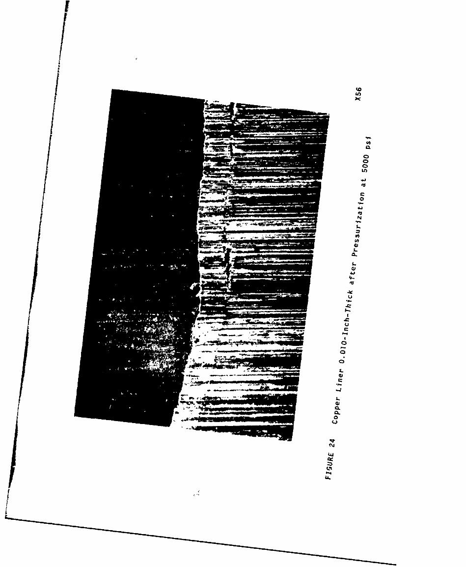
A copper liner, 0010-inch thick, was fabricated andpressurized at 5000 psi. The vessel was sectioned for ex-amination, and good contact with the tube wall was demon-strated. Again, in the area of the projection, a gap oc-curred between the projection edge and the tube wall. Withthe 0,010-inch-thick copper liner (Figure 24), a gap of0.021 inch was measured. If gap width is assumed to be di-rectly related to material thickness and inversely relatedto applied pressure, the result cited above can be predicted.A review of test data appears to corroborate this hypothesis.A simple rational explanation of the results achieved hasbeen proposed and could probably be used to predict futureresults. This finding is discussed in a later section.
5, AN EXAMINATION OF A G.E PRELIMINARY TEST
One sample has been received that was made at GeneralElectrc, Cincinnati Although the sample is from a prelim-inary test only, some important features of the probableeffects of the attachment of tantalum alloy liners to SAE4130 steel are clearly demonstrated in Figure 25. The outersleeve shown is SAE 4130 steel with a 0.10 by 1/8-inch widegroove. T he liner is Ta-2.5W alloy, 0015-Inch thick. Theliner was applied as a slip fit to the sleeve and edge-brazedwith copper by the electron beam process to form an evacuatedenvelope. The sealed liner was then isopressed for 30 min-utes at 1600OF followed by 5 hours at 18501F No evidenceof actual bonding exists between the liner and the steeleven after exposure at 1850,F Conformance of the tantalumalloy liner to the projection (which in this case is a groove)has not occurred Some evidence ot a shear edge on the tan-talum liner 3nd slight deformation of the steel is present.Although not shown in the photomicrograph, the tantalum lineractually fractured at its inner surface coincident with theedge of the groove Another point of interest is evident at
32

........ ''l ... ....1
-'
(a) aa18lcoy
(b)
FIGURE 23 Monel 0 .005 -Inh -Thick Cr s 50ciowith View of
(a) Springback during Preparation,6 Pi Ujt:J-. Ull dflu' Litter' dS Fressurizf..
33
IV
II
/ C00--
4,4
U.

ip P
v V
_. _ , i C.# '.•' U o-"•
C,..
oI 2bK /I/. 0*.S. ,., ' ,.t
I
,44.
SI * I, * ,'po
o, *.. . .t.J 0
Ue-
35 ', ,* ,
* AD
I I
35
the center of the groove. The tantalum liner has deformed
the steel at the center of the groove because of the superiorI strength of the liner at the gas pressure bonding tempera-ture. This behavior reveals that the liner is more likelyto deform the projection than be deformed.
6. DISCUSSION
During the initial stages of pressure application, theinternal sleeve or pressure vessel expands toward the wallof the outer vessel in a relatively uniform manner. Theinternal pressure creates a tensile stress in the cylinderas = pd/2h. In one case, the applied pressure is 10,000 psi
with a nominal 1-inch diameter and a 0005-inch wall thick-ness. Stress applied is therefore 1000 kpsi, and the lineris forced against the wall. Once the liner reaches the wall,however, a different case exists in the area of the projec-tion. Perhaps the following observation is an oversimplifi-cation: the assumption, however, is that the material nowbehaves as if it were a rigidly supported simple beam. Atwhat point would the beam be capable of supporting theapplied 10,000 psi load without further deformation into thecorner of the projection?
Re-examination of the test data shows that the Monelliner of Oo020-inch thickness and yield strength of approxi-mately 40,000 psi results in a gap of 0.10 inch at the baseof the projection, whereas the 0,010-inch liner in Monelannealed before test and probably with a yield strength of25,000 psi leaves a gap of 0 025-inch or 0.040 inch when notannealed.
A simple calculation of the effective load between theprojection edge and the point of contact with the tube wallreveals that the material does indeed behave as if it werea simple supportive beam, The length of material from theedge of the projection to the point of contact can then bepredicted if yield strength of the material, thickness ofthe liner, and applied pressure are known.
The additional elastic movement during the test, againon the basis of simple beam deflection calculations, can beconsidered practically negligible at the test parameters.
Accordingly, projection of data can be considered forall materials, thicknesses, and temperatures of gas pressureapplication provided the yield strength of the material atany given temperature is known. Predicted information ispresented in the next section on the basis of this hypoth-es is.
36

The material must be at or above its flow stress atthe particular strain rate and temperature imposed on thespecimen so that movement into the corner of the projectioncan be obtained. The conditions of high temperature andhigh pressure necessary for the examination of the liners,in this manner, cannot be achieved under the present ex-perimental setup and would be extremely difficult to achievepractically. With high projection angles, the only conditionsindicated under which a reasonable facsimile of the projec-tion can be produced are those Involving extremely thinliners and force exceeding the liner material flow stressduring the test. With a 0.005-inch high projection, theliner thickness is estimated to be less than 0.001 inch toprovide reasonable conformity to the projection surface.Provisions of some radii at the projection corners would helpin prcducing a satisfactory lining arrangement, especiallyif the subject material has low ductility values.
To facilitate liners of several thicknesses for the pres-ent program, alloy cF one size was purchased, rolled to therequired thicknesses, bent into a tube shape, and longitu-dinal seam-welded. This method has proved troublesome be-
cause, for effective joining, specific jigging is requiredfor each thickness, and welding procedures must be individ-ually developed. Practical limitations in the production ofliners in this way have required approximately 0.030-Inchclearance between the completed liner tube anc the pressurevessel wall. Some ductility is, therefore, exhausted inpressing the liner against the wall. For prototype gun barrelmanufacture, only slip-fit seamless tubes are recommendedto provide the maximum available ductility for forming, aroundthe projection, and the minimum risk of rupturing the linerduring the gas pressure joining process.
Defining the bonding parameters for tantalum alloy linersis still questionable. In this program, no evidence of bond-ing has been observed between the nickel alloy and the steelpressur2 vessel at temperatures up to lO000F and at an ap-plied pressure of 10,000 psi Obviously, no bonding of thetantalum .lloy will occur at these parameters either. Gen-erally, the rule of thumb used for the onset of diffusionbonding is that the materials involved must be subjected toa temperature of at least 0.4 Tm, which is approximately1400F for nickel and steel. With dissimilar metals, theparticular metal couple probably indicates whether the loweror higher melting material will satisfactorily create a con-tact surface area sufficient for interface diffusion to occur.With the use of the Ta-lOW alloy as the example, a tempera-ture for satisfactory bonding will be at least 2500*F.
37

A relatively high bonding temperature and a very thinliner are necessary to achieve the desired lamination. Theprocedure cannot be carried out on a finished gun barrel,but it must be performed at an intermediate production stage.Possible deformation of the projections at the high bondingtemperatures must be considered. From these considerations,direct bonding tends to become unsuitable.
7. PREDICTED LINER PROFILES
Test results have revealed the possibility of a re-lationship between liner yield strength at bonding tempera-
ture, projection profile, and applied gas pressure by whichthe capacity of a liner to assume the shape of a projectionon the inner surface of a gun barrel is determined.
The form and validity of this relationship have beenexplored to examine the feasibility of producing a predic-tive result. On the assumption of the load-supportiaig beamconcept, the free length of liner adjacent to a projectioncan be estimated by multiplicatior of the yield strength ofthe material and its thickness, and division by appliedpressure to maintain the load without further deformation.
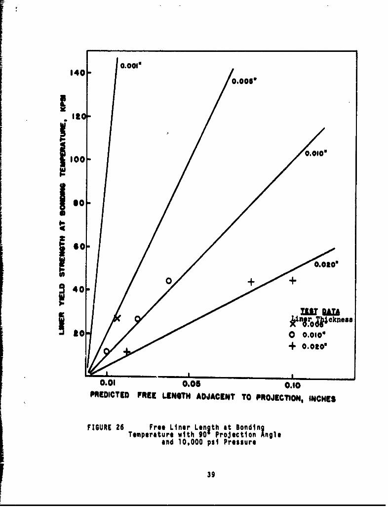
The result is graphically presented in Figure 26, with linerthicknesses from 0o001 to O.020-4nch.
Actual test data were then taken and superimposed onthe graph. With allowance for alternative test pressuresand yield strengths of the materials used in the program, agood fit is obtained. The yield strengths are estimated;but, even with possible error, the data points are of thecorrect order and tend to substantiate the contentions made.Preferably, further tests should be carried out now to pro-vide further proof, but this action is impossible on thepresent program. However, the results are so interestingthat the relationship for all important parameters was ex-amined to estimate the practical possibilities of liner ma-terials and rifling projections,
A projection angle of 45" was chosen for the data pre-sented in Figure 27 The maximum yield strength materialthat may be used to produce profile conformity with varyingprojection height at selected liner thicknesses is prediccedby the lines. This presentation shows clearly that a Ta-IOWliner at 1600*F and 10,000 psi applied pressure must not bethicker than 0.001-inch with a projection height of 0.007-Inch and 45: angle to achieve conformity to the surface.
38
1401 o0.0018
0.0056
loo- 0.0104
so-O.OO"
G-o
to 0 0.0100I
0.01 0.05 0.10PREDICTED FREE LENGTH ADJACENT TO PROJECTION, INCHES
FIGURE 26 Free Liner Length at Bonding
Temperature with 90 Projection Angleand 10,000 psi Pressure
39

140 0.001" t 0. " t 0.0104 t
20
_ 00
. •, To -tOW st 14000eF
0
.JV Go
40O
20,o a
0.05 0.10PROJECTION HEIGHT, INCHES
FIGURE 27 Projlection Height Necessaryfor 45* Angle Conformity to Various
Liner Thicknesses and-.to 10,000 psi Pressure
40

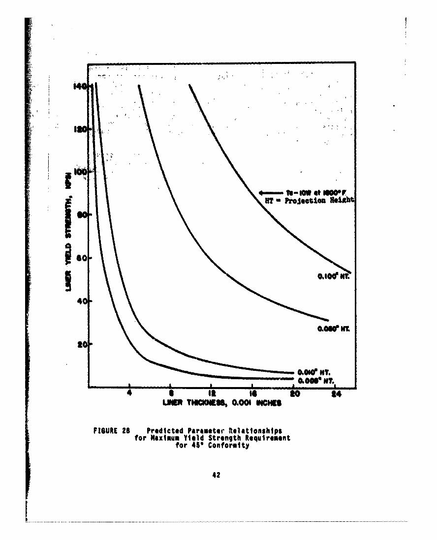
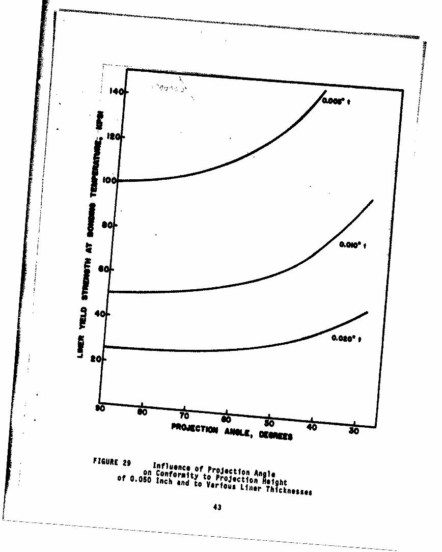
A different plot is made in Figure 28 to illustrate thestrong influence of liner thickness on the capacity to con-form to a surface, especially at small projection heights.The plot shows that, to produce required results with an0.008-inch-thick liner of tantalum alloy, a projectionheight of at least 0.050 inch is needed. The influence ofthe projection angle is illustrated for two projectionheights in Figures 29 and 30. In these figures is shownhow the low-angle projections help to improve liner confor-mity to profile.
All predictive graphs, Figures 26 to 30, were construc-ted at 10,000 psi pressure. Howeve.', since piessure affectsthe result inversely in a linear manner, substitution of thedesired pressure is easily accomplished. Besides, the follow-ing ormula may be used to calculate the estimated gap with
90projections:
Length of gap -~ (yt/p)2 - h2
where ay Z liner yield strength at test temperature, psi
t = liner thickness, in.
p - test pressure, psi.
h - projection height, in.
Consideration of the validity of the predictions pre-sented in Figures 26 to 30 reveals that the concept probablyapslies fairly accurately to 3rojectton angles of less than60 . An increasing degree of error will occur at higherangles because of localized work-hardening and because ofthe reduced effective beam length in the final stages of pro-file formation. However, the rules appear to be generallyapplicable to determine whether a particular series of ex-periments are likely to succeed. The rules clearly demon-strate that Ta-lOW liners of sufficient thickness for prac-tical use cannot reproduce the gun barrel projection profile.
41
HT pftjeotiou valkb
j*0
40
110
4 Ilk t Itoe 14L R ThICKEIS 0.001 INCHS
FIGURE 28 Predicted Parameter Relationshipsfor Maximum Yield Strength Requirement
for 45' Conformity
42
'4 4
0000@0,
P, acreog A"., 4
FIGURE 29 onfluence Of ProJection An .on Conformlty to ProJection *lifht
of 0.060 Inch and to Various Liner Thicknesses
43

1140, .0.Oo0 t
IIw
so 0.0014 t
z
4003
PROJECTION ANGLE, DEGREES
FIGURE 30 Influence of Projection AngleOn Conformity to Projection HeightOf 0.005 Inch and to Various Liner Thicknesses
44

8. CONCLUSIONS
1. Surface replication of a prerifled barrel projection
on a liner cannot be achieved with Ta-lOW in liner thick-nesses considered desirable with a gas pressure bonding tech-nique.
2. A reasonable prediction can be made that, with a450 angle projection, a Ta-lOW liner of less than 0.001 inchwould be necessary at 0.005 inch projection height providedthe projection itself could sustain the load.
3. Tests indicate that the steel gun barrel materialwill become deformed below the bonding temperature requiredfor Ta-lOW.
4. Tests with low yield streigth liner materials, copperand Monel, did not provide good profile conformity; gaps re-main adjacent to projections.
5. Tests with low yield strength liner materials re-vealed a general relationship that app_:rs to quantitativelypredict results accurately enough for practical use.
9. REtOMMENDATIONS
Efforts to join a liner material to a prerifled gun tubeby gas pressure bonding techniques should be discontinued.Test results from this program indicate that application ofthis technique is impractical to obtain liner conformity torifling profile.
45