Embed Size (px)
Citation preview

89
MODULE
may already know from other Creo platesetters. In this module you will learn about the disegno base of the TH2 so that you can capire how it exposes and thus troubleshoot diagnos problem .
Le on n Modulslide 4-1
Lesson 1:
Lesson 2: Descrivi la TH2
Lesson 3: Identif Component Thermal Head
Lesson 4: Identif Component in the O tica
zi Questo o
Il D segno Della Testa Di Esposizione
ica i i della II
ica i i Parte t
Segui le Guide di sicurezza
La Testa di Esposizione Termale II della Creo (TH2) si diferenzia dalle altre thermal head that you
i meglioticare ie
Preche u T Hai Bisogno Di Saperlo
Ii
Manuale del utente finale
Termica II (TH2)i

Modul 4: Design of the Thermal II Exposure Head (TH2)
90 Student
Follow the Safety Guidelines
slide 4-2
Understanding the Dangers and Safety Issuesslide 4-3
The TH2 uses two separate laser emitters:
• Write laser
• Autofocus laser
Laser Emitters
Write laser
slide 4-4• The write laser beam is invisible (class IV, approximately 830 nm). You can tell
that the write laser is on when the red LEDs are flashing on the head. Under normal operating conditions, with doors and covers in place, you should never be able to see the LEDs flashing.
• The write laser interlocks must never be defeated by the operator or service personnel!
Why You Need to Know ThisThe thermal head contains a potentially hazardous infrared laser. You should be aware of all the necessary safety requirements and precautions before you start working with it. In this lesson you will learn about the safety guidelines for working with the TH2.
What You Need to Know• The danger and safety issues
Lesson1Lesson1
o Il
Guida del e

Follow the Safety Guidelines
91
slide 4-5
Autofocus laser
slide 4-6• The autofocus laser is visible (red, class IIIB, approximately 670 nm).
• The autofocus laser interlock may be defeated by an authorized Creo service engineer only, while following all safety instructions listed in the service safety documentation.
slide 4-7
Class 1 Maximum Permissible Exposure Classificationslide 4-8
• Laser products are identified by a classification which has a Maximum Permissible Exposure for that class.
• If the product containing the head meets Class 1 Maximum Permissible Exposure, then special protective equipment, training and environment will not be needed.
slide 4-9
Danger: Do not operate the Creo Thermal Imaging Head outside the platesetter or with any doors or panels open, nor bypass any of the laser safety mechanisms.
The laser output can cause severe and permanent eye and skin damage and is a fire hazard in the presence of flammable materials.
Warning: Head installation requires that some door panels be open. Read the installation procedure and follow all safety precautions.
Danger: Do not look directly or indirectly into the autofocus laser. The laser radiation can cause permanent eye damage if reflected directly or indirectly into the eye.
When the platesetter is closed and protected (interlocks and panels are all closed), it is a Class 1 laser: customers are allowed to use this device with no protection.
When the platesetter is being servizio, it
Classe 4 laser. I clienti should not be around when the platesetter is open.
Manuale del ute te finalen
non e piu Classe 1. Rather, it becomes a

Module 4: The Design of the Thermal II Exposure Head (TH2)
92
Identifying the Safety Mechanismsslide 4-10
• Light tight doors & panels
• Abort buttons
• Redundant door switch interlock system
• Software safety feature: You can use the firmware to disable the laser:At the TH2 > prompt, type set sys laserenable 0
• Together with the laser interlock system, the platesetter enclosure is designed to protect anyone in the platesetter vicinity from exposure to the laser radiation by enclosing the laser radiation within the platesetter.
slide 4-11
Note: After performing any service activity and before switching on the platesetter, you must check and ensure that all external and internal enclosures are complete, not broken or cracked, and properly assembled to the platesetter.
For more details on safety precautions:Lotem 800 II Family Safety Precautions for the User (part number 399Z3R854A)
Danger:
If the platesetter is ON and the enclosure is damaged or incomplete, and even with the doors closed, then visible or invisible laser radiation may be present. This radiation is hazardous to the eye or skin. Even brief exposure of the eye to this radiation or its reflection from shiny or matte objects can cause permanent degradation or loss of eyesight!
Guida del Studente

Describe the TH2
93
Describe the TH2
slide 4-12
Benefi TH2slide 4-13
benefi Creo TH2, comp TH1 :
• Increased reliability
• Decreased manufacturing and Returned Materials Authorization (RMA) costi (how much is spent to get the head as good as n and )
•
•
Why You Need to Know ThisThis lesson introduces you to the TH2, its benefits, and specifications.
What You Need to Know• The benefits of the TH2
• The specifications of the TH2
• About square spots
Lesson2
pronta da essere speditauova
Piccole dimensioni, to fit more imaging platforms
Manuale del utente finale
Capire i vantaggi e i ci della Testa Termale
arati alla vecchia sonoci dellaI Testa Testa
unaltr voltaa
Potenza maggiorata

Module 4: The Design of the Thermal II Exposure Head (TH2)
94 Guid
TH2 Specifications
slide 4-14• 125 Mbit/secondo data rate
• 224 canali
• 18.5 W stroke flattened
• ± 0.15 millimeter focus rangeThis focus range is about 1/3 meno than that of the TH1. A Z-stage is used to effectively range of media thicknesses (see Examining the Z-Stage on page 146).
• diferent resolu ion : 1200, 2400, 2540, o 3200 dpi (The 1200 and 3200 dpi heads are not normal us Lotem Quantum.)
slide 4-15• º º
• : 5% o 90% RH
• Enclosure sealing: IP 54The seal on the TH2 is an improvement on the TH1 to prevenire polver incursion
.
Square Spots slide 4-16
What does a pixel actually look like?
high. So how do we make a square pixel?
Thermal II Exposure Head 1200 DPI Performance Specification:http://techplanet.creo.com/idoc/72/3563A/A/72-3563A-A-SP01.pdf
Thermal II Exposure Head 2400/2540 DPI Performance Specification:http://techplanet.creo.com/idoc/72/3557A/A/72-3557A-A-SP01.pdf
Thermal II Exposure Head 3200 DPI Performance Specification:http://techplanet.creo.com/idoc/72/3558A/A/72-3558A-A-SP01.pdf
sulla Lastra dopo
Esposizione
Quattro iTeste con z iSono alide Vmente ati nell
Temperaturea dell Ambiente 15 C o 40
à fin a
(Punto Quadrato)
Ci Sono 240 pixels. Ogni pixel e Largo 10.6 microni. But they are only 2.4 microns
Noi rotiamo il tamburo. La rotazione del tamburo fa il square spot, like a paintbrush.
a del studente
aumentare il che puo essere inciso
da fin a gradi C
Umidita dell ambiente da
Ambiente di L voroa
dentro la testa

Describe the TH2
Ma 95
The profile in this direction is very sharp. Side to side, we have this beam that is uniform. Between the swaths you will get a drop-off profile.
slide 4-17
ota ion
10.6 µ2.4 µ
Perche li Spot g Sono quadrati
R z e Del Tamburol
nuale del utente finale

Module 4: The Design of the Thermal II Exposure Head (TH2)
96 Guid
Identify Components of the Thermal Head
slide 4-18
Overview of the Thermal II Exposure Headslide 4-19
The machined aluminum optics cavity contains the optical and sensor systems, isolating the optics from the rest of the head enclosure. There are no circuit boards in the optics cavity. The TH2 is cooled by means of a hybrid heat waste management system.
slide 4-20
Write-Laser-Power (WLP) Board
slide 4-21• Channels all power and signal lines
• Drive for write laser (70 A)
• Drive and servo for thermo-electric Peltier (TEC) coolers
• Drive for cooling fans and the external shutter
Head-Controller (HC) Light-Valve Driver (LVD)
slide 4-22• The head-controller (HC) section is the main interface to the outside:
– Main processor system
– TMCE to head link (the redirect function)
– Analog and servo functions
Why You Need to Know ThisIt is important for you to be able to identify the components of the TH2 and understand their function because of the types of errors that you will encounter in the field. This lesson describes the circuit boards and other components of the thermal head and their functions.
What You Need to Know• About the circuit boards in the TH2
• How the cooling system works
Lesson3
a del studente
Tutta la testa deve essere sostituita con il costo di 36,000 dollari. Una bella bastonata alla tasca de cliente.
Le Schede Dentro La Testa Thermale TH2 Reparto O tictdelle he( )
e la scheda del
Premessa Nessuna delle schede della Testa puo essere riparata dal Cliente.E se qualsiasi della schede si guasta, l

Identify Components of the Thermal Head
Ma 97
• The light-valve driver (LVD) section includes the serial hotlink data connection:
– Drive is high voltage and fast
– Data rates are limited by the number of switchings / unit time
Write Laser Emission Indicator LEDsslide 4-23
High intensity red LEDs are mounted on the casing of the thermal head. These write laser emission indicator LEDs are wired directly to the laser diode’s power source. They blink when the write laser is powered up. If these lights are blinking, it means that the write laser is emitting hazardous infrared light.
Board Cooling Systemslide 4-24
• Must meet IP64
• Air cooled to remove waste heat
• Hybrid cooling system, consisting of the following elements:
– Peltier coolerA Peltier cooler (also known as a thermoelectric, or TE cooler), acts as a heat pump using the Peltier Effect. The Peltier Effect occurs when you send an electric current through two dissimilar metals connected at two points, causing one point to become warm while the other becomes cool. You can then use this effect to transfer heat from one side of a device to another (from inside an enclosure to the outside, for example).
– Contact cooling
– Cold plate and fin tube
– Fans
– Cooling fluid
Danger: Do not look into the interior of the platesetter if the write laser emission indicator LEDs are blinking. Direct contact with the laser or any stray laser light can cause permanent damage to exposed eyes or skin. If the write laser emission indicator LEDs are blinking, immediately close all doors and shut off power to the platesetter.
nuale del utente finale

Module 4: The Design of the Thermal II Exposure Head (TH2)
98 Guid
Apply What You Know
slide 4-25Activity: Board Quiz1. Which board in the optics cavity channels all the power and signal lines?
__________________________________
2. What does LVD stand for? __________________________________
3. In Splot, you can either talk to the TH2 or to the TMCE board. Which board enables this redirect function?__________________________________
a del studente

Identify Components in the Optical Path
Ma 99
Identify Components in the Optical Path
slide 4-26
Why You Need to Know ThisUnderstanding the optical path is necessary for you to be able to identify the various components in the head, and to learn the acronyms used throughout the firmware. In this lesson you will follow the path of the light from the laser diode to the media on the drum.
What You Need to KnowAbout the following components in the optical path:
1. Beam Position
a. Actuator
b. Servo (sensor and actuator)
2. Light valve
a. Stroke calibration (stroke flattening)
b. Slope and curve adjustment
3. Laser Power Control
a. M8 sensor
b. Shutter sensor (beam balancing and power calibration)
4. Autofocus System
a. Position Sensitive Device sensor
b. Hall sensor
c. Focus actuator
d. Focus Range Finder
5. Magnification
Lesson4
nuale del utente finale

Module 4: The Design of the Thermal II Exposure Head (TH2)
100 Guid
Analyzing the Optical Pathslide 4-27
The very basic optical path is as shown below: Laser emits light, goes through lenses and a light valve, and then reaches the media on the drum correctly focused.
Basic optical path of the TH2
slide 4-28
Drum
Lightvalve (LV)Laser
Illumination Path Imaging Path
High power 40 W laser diode
240 switchablelight gates
Media on drum
M8 sensor
Laserdiode
Light valve
Prism
Mirror Mirror Tilt mirror
Use these objects to redirect the light emitted from the laser, through the light valve, onto the M8 sensor above.
a del studente

Identify Components in the Optical Path
Manuale del utente finale 101
Use the box below try to sketch the optical path:
M8 sensor
Light valve
Laserdiode
Module 4: The Design of the Thermal II Exposure Head (TH2)
102
slide 4-29
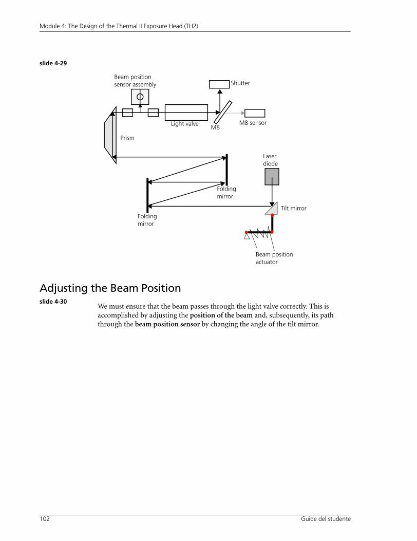
Adjusting the Beam Positionslide 4-30
We must ensure that the beam passes through the light valve correctly. This is accomplished by adjusting the position of the beam and, subsequently, its path through the beam position sensor by changing the angle of the tilt mirror.
Light valve M8 sensor
Prism
Folding mirror
Folding mirror
Tilt mirror
Beam position actuator
M8
Beam position sensor assembly
Laserdiode
Shutter
Guide del studente
Identify Components in the Optical Path
103
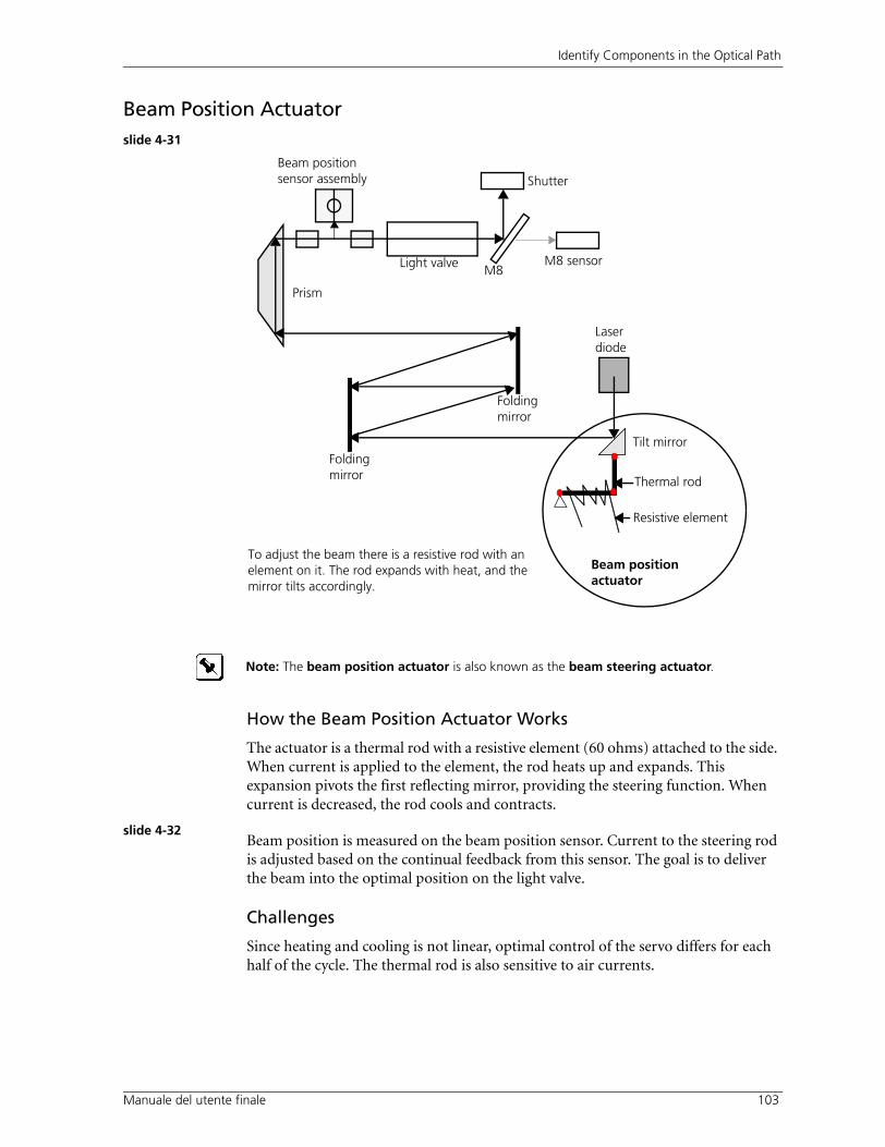
Beam Position Actuatorslide 4-31
How the Beam Position Actuator Works
The actuator is a thermal rod with a resistive element (60 ohms) attached to the side. When current is applied to the element, the rod heats up and expands. This expansion pivots the first reflecting mirror, providing the steering function. When current is decreased, the rod cools and contracts.
slide 4-32Beam position is measured on the beam position sensor. Current to the steering rod is adjusted based on the continual feedback from this sensor. The goal is to deliver the beam into the optimal position on the light valve.
Challenges
Since heating and cooling is not linear, optimal control of the servo differs for each half of the cycle. The thermal rod is also sensitive to air currents.
Light valve M8 sensor
Prism
Folding mirror
Folding mirror
Tilt mirror
M8
Beam position sensor assembly
Laserdiode
Beam position actuator
Thermal rod
Resistive element
To adjust the beam there is a resistive rod with an element on it. The rod expands with heat, and the mirror tilts accordingly.
Shutter
Note: The beam position actuator is also known as the beam steering actuator.
Manuale del utente finale
Module 4: The Design of the Thermal II Exposure Head (TH2)
104 Guid
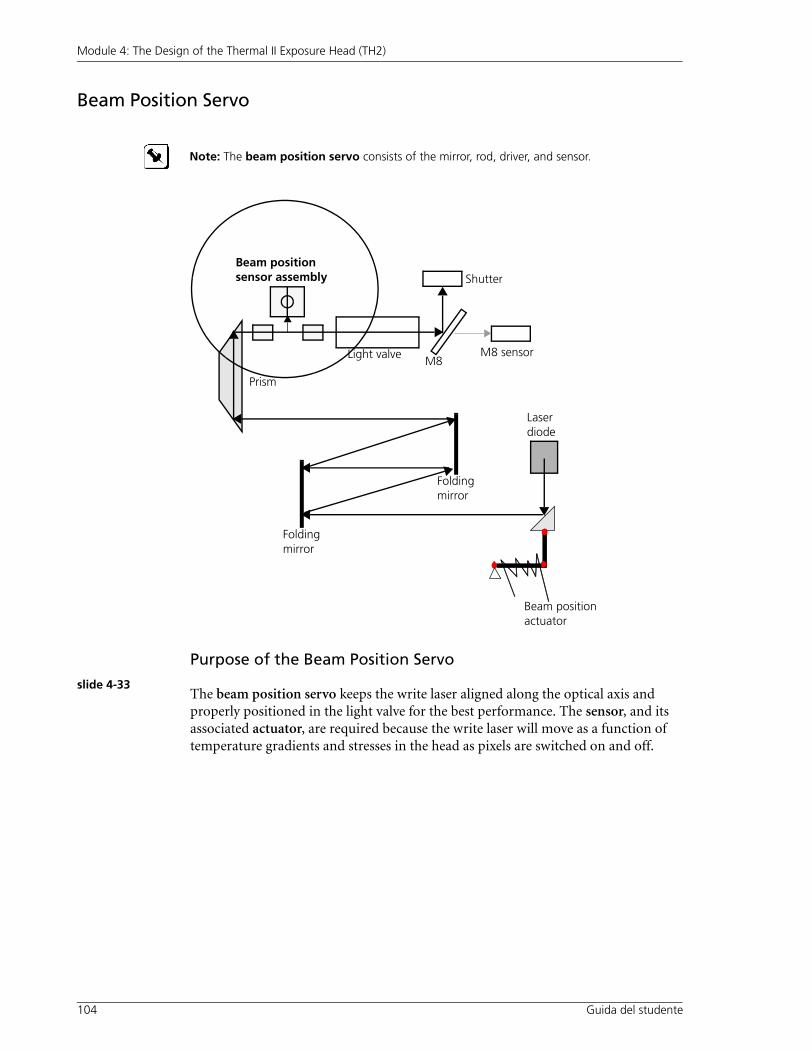
Beam Position Servo
Purpose of the Beam Position Servo
slide 4-33The beam position servo keeps the write laser aligned along the optical axis and properly positioned in the light valve for the best performance. The sensor, and its associated actuator, are required because the write laser will move as a function of temperature gradients and stresses in the head as pixels are switched on and off.
Note: The beam position servo consists of the mirror, rod, driver, and sensor.
Light valve M8 sensor
Prism
Folding mirror
Folding mirror
M8
Beam position sensor assembly
Laserdiode
Beam position actuator
Shutter
a del studente

Identify Components in the Optical Path
Ma 105
Apply What You Know
slide 4-34Activity: Find the Problem in the TH1 SensorsWe want to make sure we get maximum power out of the light valve. Examine the setup below, and think about some problems that could be experienced with such a setup.
Identify two problems with the above TH1 setup:
___________________________________________________________________
___________________________________________________________________
___________________________________________________________________
___________________________________________________________________
Beam position sensor
Beam (Gaussian beam)
Beam position sensor
nuale del utente finale

Module 4: The Design of the Thermal II Exposure Head (TH2)
106 Guid
slide 4-35
How the Beam Position Servo Works in the TH2
A portion of the write beam is taken from the edge, where it is unusable for imaging. This beam is directed onto a split detector. An error signal is generated based on how much light falls on each side of the split detector. A proportional integral derivative (PID) servo control loop is used to optimize the position of the beam going into the light valve.
Light valve
Beam
A B Split sensor
Beam Position ServoA prism cuts off the beam, so there is insufficient energy to damage the sensor.
For further information about the beam position servo:http://techplanet.creo.com/output/computer_to_plate/lotem_quantum/content/documentation/Thermal2sensors.pdf
a del studente

Identify Components in the Optical Path
Manuale del utente finale 107
Making the Wide Beam of the Write Laserslide 4-36
Schematic of the write laser diode assembly
Advantages of the Wide Beam
slide 4-37This method provides uniformity across the beam. If one area on the write laser becomes weak, causing a drop in power, the overlap of the other sections will compensate for the weak section.
The system will recalibrate itself to provide the correct power.
Power Increases until Shutdown
If the current increases over time to maintain the same output power, it could be due to lens or laser failure. If the current rises above the nominal laser current specified in the head NVS parameters, it is an indication that the head may be failing. The head shuts down automatically when current rises 20% above the nominal value. The service engineer should monitor the head over a period of days or weeks, and discuss with Product Support if a head replacement is necessary.
Light valve 240 individually controll
Lente
d
Lenses to direct laser light
pixsel atiDiodo laser
i scrittura

Module 4: The Design of the Thermal II Exposure Head (TH2)
108 Internal Student Guide
Understanding the Light Valveslide 4-38
The light valve is at the heart of Creo’s thermal head technology. It enables us to divide the beam into 240 individual pixels (or 120 channels), though, in production, we limit this number to 224 pixels.
• Each of the 224 pixels are individually addressable, meaning that each can be turned on or off during imaging.
• During stroke calibration, power to each channel can be attenuated by up to 30%. We calibrate to equalize the power across the pixels. This is called “stroke cal”.
Comparing the Fiber Head with the Thermal Head
slide 4-39The thermal head technology is very different from the fiber head technology:
Performing a Stroke Calibration (Stroke Cal)slide 4-40 1. When you issue a Stroke Cal command, the head turns on all pixels, in pairs, to
100% brightness. We measure in pairs because:
a. The BBS sensor is heat sensitive. We use pixel pairs because it is the least number of pixels that will still create enough thermal energy to differentiate from background noise (leakage)
b. It is not likely that adjacent pixels will have very different power (in a normal, operating head)
slide 4-41 2. The brightness level for each pair is measured using the shutter sensor. The laser light must be filtered, otherwise it would saturate (over-power) the sensor. A filter on the shutter sensor reflects 99% of the laser light (only 1% of the laser light actually reaches the sensor).
T
24 o 48 beams (came from 24 o 48 dio ) in 240 pixel
Wavelength can vary from 830 - 845 nanometers
beam
1% laser attraversa
FiltroShutter sensore
Laser
il shutter sensoredell
1%
Testa a fibre ( otem )L vecchi
separatidiUnico beam che viene splittato (diviso)
esta termale con un diodo d 50 Watt20-
Un unico e una sola lungezza di luce 830nm( )
a
Identify Components in the Optical Path
Ma 109
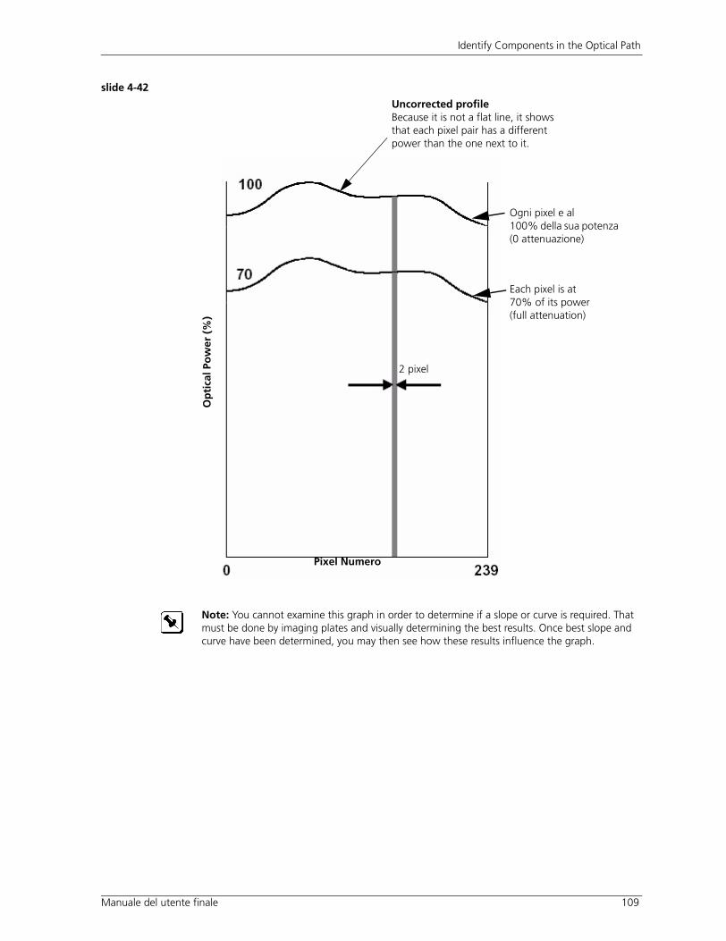
slide 4-42
Uncorrected profileBecause it is not a flat line, it shows that each pixel pair has a different power than the one next to it.
2 pixel
Pixel Numer
Op
tica
l Po
wer
(%
) pixel a
100% s po (0 attenuazione)
Each pixel is at 70% of its power (full attenuation)
Note: You cannot examine this graph in order to determine if a slope or curve is required. That must be done by imaging plates and visually determining the best results. Once best slope and curve have been determined, you may then see how these results influence the graph.
nuale del utente finale
Ogni e ldella ua tenza
o

Module 4: The Design of the Thermal II Exposure Head (TH2)
110 Internal Student Guide
slide 4-43 3. The head creates a look-up table (stroke table) of values between 0-255 to calibrate all pixel pairs to match the lowest measured pixel value. This process is known as stroke flattening or stroke calibration.
slide 4-44 4. n stroke automatica :
– At regular (adjustable) intervals
– media
– reset (Lotem)
stroke cal. The Level 0 indicates the profile of the swath with no attenuation, and the Level 255 shows the profile of the swath with full attenuation.
The stroke cal then attenuates pixel pairs down to the level of the weakest pixel pair in the swath and thus flattens the profile. It may take several iterations to flatten the stroke to within the limits determined by the parameter BBS Maximum Errore.
2 pixels
Pixel Numer
Uncorrected profile
Op
tica
l Po
wer
(%
)
ma im BBS Error
LVD all Level 255Stroke profilo
LVD all Level 0Stroke profile
o
Profilo Corretto (flattened) (apittito)
e Massimo
Posizione beamss oerrore
Una uova tabella viene creata mente
Quando cambi il tipo della lastra ( )tu
tiQuando tu il CTP
Il grafico above shows how the profile of the swath is flattened when you perform a

Identify Components in the Optical Path
Manuale del utente finale 111
slide 4-45
e mp stroke .
BBS Maximum Error, it does not have to be horizontal. This is because the sensor can m sur POWER, POWER DENSITY.
pixel he stroke cal routine would likely try to flatten to 100% della potenza
pixel
70% della potenza di pixe
Beam Balance
Stro
ke, A
ll Le
vel 2
55, B
alan
ced
, All
Leve
l 0
Pixel
correzione dei valori stroke,che corispondono ai valori
Risultato del
Quest coppia di sono le uniche ce
di ogni coppia di
Questa e la linea calibrata,
piu deboli coppie pixee apiattita al livello delle
l
ogni coppia di l
Questa linea representa la
.
nella tabella stroke .
Coppie iD
se ioIl grafico riportato sopra e nu di un profilo molto buono
E importante capire that, although this line needs to be smooth, to within
i are e non solo

Module 4: The Design of the Thermal II Exposure Head (TH2)
112 Internal Student Guide
Output Power versus Power Density slide 4-46
The stroke calibration that is done in the TH2 can only balance the power of adjacent pixels. The beam balance shutter cannot adjust for power density. To understand the effects of slope and curve, you must first understand the difference between power and power density.
The output power of the head is the power of the beam. This power generates heat, and heats up the plate. Power density is the power of the spot itself, and is influenced by three factors:
a. Focus
b. Spot size
c. Power
These three factors will affect power density, and therefore how the spot is exposed on the plate. Since...
slide 4-47
Power Density = Power / Spot Area
• As Power increases------------------ Power Density INCREASES
• As Spot Area increases-------------- Power Density DECREASES
We will assume that focus has been correctly set up.
It is not within our control to vary the size of the spot. Therefore, in order to obtain a balanced POWER DENSITY across the swath, we must adjust the POWER to each pixel.
slide 4-48During the beam balance, the head uses the BBS sensor to match the power of adjacent pixels, so we know that the POWER is uniform across the swath. Since, across the swath, each pixel may vary in size from its neighbor, the power density will vary accordingly. Therefore, if we have, for example, a pixel with a larger dot beside a pixel with a smaller dot, we need to increase the power of the large dot, or decrease the power in the smaller dot in order to balance POWER DENSITY.
slide 4-49If the power density is not uniform across the swath, we get banding. In the next few sections, you will learn to identify the effects of slope and curve.
E bandingsempi di

Identify Components in the Optical Path
Ma 113
1. Slope Banding: Beam Slopeslide 4-50
In the example below, banding is caused by the increase in spot size across the swath, causing a decrease in the power density across the swath.
slide 4-51
slide 4-52
Power density
, la potenza di incisione sulla
Applicando il BMSlope linearly abassa la potenza del laser per canale con la intenzione di bilanciare la potenza
.
nuale del utente finale
La dimensione dei Spot puo variare da un canele al prossimo
lastra si abassera quando le dimensioni dello spot crescono.
se il beam (fascio laser) non e parallelo alla lastra. se ogni canale ha la stassa potenza degli altri
e la densita sulla lastra

Module 4: The Design of the Thermal II Exposure Head (TH2)
114 Internal Student Guide
slide 4-53The platesetter thinks that the power across the swath is the same. We have to be able to say that we want more power on the right hand side. According to the stroke-flattening graph, the weak pixel is already on the right hand side (in terms of power). If you need more power on the right-hand side, you have to tilt the graph so that the left side slopes downward, thus the density will be corrected.
• Beam slope is an adjustable media parameter used to match the pixels at the end of the swath. Beam slope can be used to correct banding.
• For example, if a swath has 224 pixels, a beam slope value of + 10% indicates that the power of pixel 0 is 10% higher than the power of pixel 223.
2. Curve Banding: Beam Curveslide 4-54
, power density is the same at either end of the swath, but curves in the middle. This means that we need to aggiungere piu power on both sides. There is no difference in density on the edges. This type of banding is more subtle, and harder to see.
+10%
Beam Slope
Nel esempio riportato sotto

Identify Components in the Optical Path
Ma 115
slide 4-55
slide 4-56
slide 4-57• Beam Curve is used to correct variations across a swath and also to correct
banding.
• The beam curve parameter applies a quadratic correction across the stroke if the beam profile appears to follow a power curve.
Most normal problems encountered with the stroke are either slope or curve banding. Because of the high quality of the TH2 manufacturing process, you will seldom encounter problems with stroking. If you do, it is within the 2% error range.
If the focus offset is changed such that the swath is focusing deeper into the plate, it could result in curve banding.
Applying a BMcurve decreases the power per channel in order to balance power density on the plate.
+10%
Beam Curve
nuale del utente finale

Module 4: The Design of the Thermal II Exposure Head (TH2)
116 Internal Student Guide
3. Stroke Correction: Scorrslide 4-58
Sometimes there are problems with an abrupt transition within the swath. This could be as a result of a scratch in the optics.
A Scorr table is set up for each head in Vancouver. You need to copy this Scorr table to each new media. This table is a characteristic of the head, and is thus unique per head.
This correction works by applying a Scorr to a certain pixel pair. If it is positive at the stroke profile, it will tone down that reading by x%.
Note: Although the ability to do stroke correction with a Scorr table still exists, it will almost never be used because of the high quality light valves that we use. No head has been shipped from Vancouver with a Scorr table in several years.
Pixel quality

Identify Components in the Optical Path
Manuale del utente finale 117
slide 4-59
Apply What You Know
slide 4-60Activity: Analyze the Banding1. Look at the example exposures that your instructor has prepared for you. Each
has a problem with banding.
2. Examine each plate and try and diagnose the type of banding it is, and how to correct it.
3. Use the table below to record your analyses.
4. Discuss the results with your instructor.
Plate Diagnosis Correction

Module 4: The Design of the Thermal II Exposure Head (TH2)
118 Internal Student Guide
Control Laserslide 4-61
, and learn how the laser power is controlled. Take a look at the M8 sensor and the shutter sensor.
slide 4-62The head has a calibrated power sensor, the BBS sensor. This sensor is initially calibrated in Vancouver and compares its values to a standard power.
slide 4-63
Light valve M8
Prism
Folding
Folding
M8
Beam position sensor
Beam position actuator
Shutter sensorassembly
Laser Power Sensore M8
Light Valve Beam
8
Lente
Sensore del Otturatore (Shutter sensor)
specchio
specchio
DiodoLaser
Sensore
a
Specchio n
lare a PotenzaL
Adesso torniamo alla otticasezione

Identify Components in the Optical Path
Manuale del utente finale 119
M8 Sensorslide 4-64
• The beam is approximately 20 millimeters wide so only half of the beam is measured.
• The beam is centered in both the horizontal and vertical planes to the sensor.
• The sensor is calibrated during integration.
slide 4-65The M8 sensor provides real-time control of the write-laser level during a plot, with one or two samples per drum rotation. Before the start of each plot the M8 will sample the beam once the power has been calibrated. During the plot the M8 will sample the beam while the head is over the clamps, and provide feedback to the laser diode driver in order to maintain the initially-sampled value.
10 mm
Swath (write beam)
M8 Sensor
For more details on the M8 sensor:http://techplanet.creo.com/output/computer_to_plate/lotem_quantum/content/documentation/Thermal2sensors.pdf
Apply What You Know
slide 4-66Activity: Think About It!
a. When does M8 sample the power of the beam? ____________________________________________________________
____________________________________________________________
b. Why does M8 sample power every revolution? ____________________________________________________________
____________________________________________________________

Module 4: The Design of the Thermal II Exposure Head (TH2)
120 Internal Student Guide
Shutter Sensorslide 4-67
The shutter sensor is used prior to the beginning of imaging for calibrating the power and balancing the beam.
slide 4-68The shutter sensor must be moved in and out of the write beam. It is closed prior to imaging and open during imaging. Current is only applied to change the state of the shutter.
slide 4-69
The shutter sensor is a two-part laminate:
• The outside coating is a dichroic filtro that reflects 99% of the 830 nm laser
• The inside layer of colored glass absorbs 830 nm laser to further attenuate the laser from the sensor
The sensor’s active area is 12 mm x 12 mm. The beam is roughly 5 mm x 10 mm.
Functions of the Shutter Sensoreslide 4-70
• Calibrates the overall laser power to the required setting.
• “Flattens” the beam such that there is equal power for every pixel pair.
Challenges
slide 4-71Firstly, the shutter sensor must be accurate over a wide range of power settings; from 3 watts to 18.5 watts. Secondly, it must be able to perform beam balance to within 2% of the power for each pixel pair.
Apply What You Know
Activity: Think About It Some Morec. What would happen if you put full power onto the shutter sensor?
____________________________________________________________
____________________________________________________________
For more details on the shutter (beam balance) sensor:http://techplanet.creo.com/output/computer_to_plate/lotem_quantum/content/documentation/thermal2sensors.pdf

Identify Components in the Optical Path
Manuale del utente finale 121
Posi ion Autof ocslide 4-72
The autofocus system ensures that the lens is optimally positioned for the best exposure. The following section will explain how it works.
slide 4-73
slide 4-74
Position Sensitive Device Sensor (PSD)slide 4-75
The focus PSD sensor is a two-part sensor. When values on both sensors are equal, the focus laser should coincide with the write laser at the focal point. In an ideal laser they should coincide. The PSD is used in the autofocus range finder to calculate the location of the centroid of the spot.
slide 4-76In an ideal head, the focus system will try to keep the focus laser spot centered on the PSD split sensor.
slide 4-77If, on the other hand, the focus laser reflection point (on plate) is not the same distance from the head as the best focusing point for the write laser, then we have to determine the correct offset. This offset is measured and monitored as an offset from the center of the PSD split sensor.
Warning: The autofocus system is a potential hazard to vision. It is highly recommended that you work wearing protective goggles. Never look at the focus laser. Be careful when observing the laser on the plate. Even a momentary flash of reflected laser light will burn immediately.
Beam Fixed lens tube
Moving focus lens tube
Flying mirror
Flying mirror
Focus error sensor PS
D
Focus laser
Should all coincide
A B
Focus and write lasers coincide
Tamburo
re qui
z ando la Testa Usando il Sistema di ou

Module 4: The Design of the Thermal II Exposure Head (TH2)
122 Internal Student Guide
The first thing to do when you install the head is to do a focus test to check whether the write laser and the focus laser coincide. (See Performing the Focus Series Test on page 217.)
slide 4-78
Split Sensor (A,B)
slide 4-79 from the focus system:
1. Sum = A + B
2. Differenze = A - B
3. Error = (A - B)/ (A + B)The error is what you use to track where the head will be installed.
In a perfect world, the error would be as above. However, the error is actually (A - B)/ (A + B) + Focus Offset + Surface Depth (SD)
A B A B
Focus and write lasers do not coincide - focus offset
Drum
Beam Fixed lens tube
Moving focus lens tube
Flying mirror
Flying mirror
Focus error sensor PS
D
Focus laser
Focus offset
Note: Different media may have different SD requirements. This is especially important with the Spectrum, where the focus must be on the point of contact between the receiver and donor in order to proof correctly.
Sometimes, the emulsion on the plates might affect the SD.
e
che tu riceveraitre valoriCi sono

Identify Components in the Optical Path
Ma 123
Hall Sensorslide 4-80
The purpose of the hall sensor is to provide a linear measure for the position of the moving lens tube.
The whole structure moves (the flying mirrors and the lens tube). You need an indication of where they are. The hall sensor is used to measure the position of the moving lens tube. It provides a linear measurement of the structure’s position. The hall sensor voltage output is amplified and level-shifted so that the output range corresponds well with the range of the focus actuator.
The hall sensor is fixed in the head. There is a magnet on the moving lens that measures the changing magnetic field. A coil (focus actuator) is used to drive the tube back and forth.
F c Actuatorslide 4-81
The purpose of the focus actuator is to implement a position control loop.
The focus actuator is a moving iron design. Displacement force is provided by applying current to a stationary coil in a ferrite cup. Restoring force is provided by springs.
Challenges
slide 4-82• The response of the focus actuator is not linear, and thus it is difficult to
implement a position control loop. The head can build up a look-up table to compensate for the non-linearity of the State Variable Feedback (SVF) control loop.
• The range finder has to work over a tremendous range of media, both textures and reflectivity.
Note: The hall sensor is also known as the focus lens position indicator.
ou o
nuale del utente finale
(focus lens position indicator)

Module 4: The Design of the Thermal II Exposure Head (TH2)
124 Internal Student Guide
Autof oc Range Finderslide 4-83
How does the head focus on the media? The focus range finder is positioned on the plate one swath ahead of the write laser.
As the drum spins, the focus laser takes samples readings of the plate, creating a profile table that will be used by the focus actuator in the following swath. This will compensate for any plate variations during imaging.
slide 4-84
To avoid focus error, flying mirrors move back to keep beam position on the focus error sensor
No Magnification With Change in Media Thicknessslide 4-85
In the TH2, there is no magnification change with a change in media thickness.
Magnification = d3/d1 Focus lens refocuses, moving forward until d3 is the same as before
Beam Moving focus lens tube
Flying mirror
Flying mirror
Focus error sensor PS
D
Focus laser Move media towards the head
Light valveFixed lens
Focus lens
d1 d2 d3
u o
Tamburo
LastraLa

Identify Components in the Optical Path
Manuale del utente finale 125
Since d1 and d3 are the same, magnification and DPI are unchanged. d2’ is larger by the plate thickness
Problem :
slide 4-86 len : a fixed lens and a moving focus lens. There is a final window.
You can clean or replace the window, but you cannot clean the lens.
Dirt on the final window
On the TH2, debris on the window will block the light, producing fine line banding. Increasing power only makes the banding worse.
The shutter doesn’t ‘see’ the dirt on the lens. When the window is dirty, you must clean it. No recalibration is needed.
Key cleaning steps:
• Always remove the head from the carriage
• Always use a new swab for each wipe (make sure that you have at least 10 swabs with you).
• Never scrub
• Never wipe in a circular motion
• Read and understand the procedure BEFORE you start cleaning
Light valveFixed lens
Focus lens
d1 d2’ d3
Window
Note: The surface of the final window is extremely sensitive. Improper cleaning and handling can permanently damage the lens. Make sure you follow the correct cleaning procedure. See the Cleaning Procedure on page 150.
Note: It is recommended that you use optical swabs, preferably from a Creo cleaning kit(part numbers 04-0012B and 04-0013A).
a Vetrino Sporco
Ci sono due ti
La Lastra

Module 4: The Design of the Thermal II Exposure Head (TH2)
126 Internal Student Guide
For the complete cleaning pro cedure:http://techplanet.creo.com/output/heads/thermal_2/content/docs/th2_window_cleaning.pdf
Note: You should always clean the window after installation.

Identify Components in the Optical Path
Manuale del utente finale 127
Apl
slide 4-87Activity: What Do These Componenti Do?This activity confirms that you understand the main components of the sub-systems before you continue working with the Thermal II Head.
1. Describe each of the following components in terms of its function:
a. Beam Position Servo____________________________________________________________
____________________________________________________________
b. M8 Sensor____________________________________________________________
____________________________________________________________
c. Shutter (Beam Balance) Sensor___________________________________________________________
___________________________________________________________
d. Autofocus Range Finder___________________________________________________________
___________________________________________________________
e. Focus Lens Position Indicator___________________________________________________________
___________________________________________________________
ica Quello Che Sai

Module 4: The Design of the Thermal II Exposure Head (TH2)
128 Internal Student Guide
Lesson S marslide 4-88
In this lesson you have learnt about the components in the optical path:
1. Beam position system
a. Actuator
b. Sensor
2. Light valve
a. Stroke calibration (stroke flattening)
b. Manual stroke adjustment
- Beam slope
- Beam curve
- Scorr
slide 4-89 3. Laser power control
a. M8 sensor
b. Shutter sensor (beam balancing and power calibration)
4. Autofocus System
a. Position sensitive device (PSD) sensor
b. Hall sensor
c. Focus actuator
d. Autofocus range finder
e. Magnification
f. Focus Actuator
____________________________________________________________
____________________________________________________________
2. Which part is used for edge detection?________________________________________________________________
________________________________________________________________
Apply What You Know
o io

Module Wrap-up
M 129
Module Wrap-upslide 4-90
Having completed this module, you should be able to:
• Take the necessary safety precautions when working with the lasers of the TH2
• Describe the Creo thermal II exposure head (TH2) specifications
• Demonstrate an understanding of the design of the TH2’s optics cavity, circuit board, and cooling system
• Describe the components in the optical path
• Demonstrate an understanding of the operation of the subsystems inside the TH2, and how they contribute to the accuracy of the TH2 imaging process
anuale del utente finale

Module 4: The Design of the Thermal II Exposure Head (TH2)
130 Internal Student Guide
Self-Assessment #4: The Design of the Thermal II Exposure Head (TH2)
This self-assessment activity will help you:
• Confirm your knowledge of the design of the Thermal II Exposure Head
– Safety mechanisms
– TH2 specifications
– Components of the thermal head
– Components in the optical path
- Adjusting the beam position
- Performing stroke calibration
- Adjusting strokes manually
- Controlling the laser power (M8 sensor, shutter sensor)
- Positioning the head with the autofocus laser (focus error sensor, hall sensor, focus actuator, autofocus range finder, magnification)
• Identify areas for more practice
How well are you doing?
Check the box that best represents your confidence in your ability to do each task.
Areas where you feel you need more training and practice:
1.
2.
3.
Important: You are responsible for your own learning. If you do not understand any of the components of this course, be sure to let your instructor know. This form can serve as a tool to communicate to your instructor any issues or problems you may have.
Very High
High Average Low Very Low
Follow the Safety Guidelines
Describe the TH2
Identify Components of the Thermal Head
Identify Components in the Optical Path

Self-Assessment #4: The Design of the Thermal II Exposure Head (TH2)
Ma 131nuale del utente finale

Module 4: The Design of the Thermal II Exposure Head (TH2)
132 Internal Student Guide