Embed Size (px)
Citation preview

8/12/2019 IJRRAS_7_3_03-IM1
http://slidepdf.com/reader/full/ijrras7303-im1 1/13
IJRRAS 7 (3) ● June 2011 www.arpapress.com/Volumes/Vol7Issue3/IJRRAS_7_3_03.pdf
236
FLOW AND CONVECTIVE HEAT TRANSFER CHARACTERISTICS OF
SPIRAL PIPE FOR NANOFLUIDS
Yanuar1, N. Putra
1, Gunawan
2 & M. Baqi
2
1 Department of Mechanical Engineering, University of Indonesia, Jakarta, Indonesia2 Master Students at Mechanical Engineering, University of Indonesia, Jakarta, Indonesia
ABSTRACT
This paper presents an experimental investigation of convective heat transfer coefficient for nanofluids using spiral
pipe heat exchanger. The aim of this study is to investigate experimentally flow and convective heat transfer
characteristics of water-based nanofluids flowing through a spiral pipe. The test section consist of spiral pipe with
ratio pitch per diameter is 7.0 and mean hydraulic diameter of 30 mm. The straight spiral tube with 1600 mm length
is used as the test section. At the inner of spiral pipe installed a circular copper pipe with 10 mm diameter.
Measurements of pressure drop and convective heat transfer are carried out for Al 2O3, TiO2 and CuO at 1% and 3%,
particle volume with pure water. The convective heat transfer coefficient of the nanofluids increases by up to 28%
at a concentration of 3 vol. % compared with that of pure water.
Keywords: Nanofluids, Convective heat transfer, Pressure drop, Spiral pipe.
1. INTRODUCTION
A coolant, or heat transfer fluid, is used to prevent the overheating of equipments such as electronic devices and
transportation. However, conventional heat transfer fluid such as water or ethylene glycol generally has poor thermal
properties. So, many efforts for immersing small particles with high thermal conductivity in the liquid coolant have
been conducted to enhance thermal properties of the conventional heat transfer fluids. The early research, which
used suspension and dispersion of millimeter- and micrometer-sized particle, faced the major problem of poor
suspension stability. Thus, a new class of fluid to improve both heat transfer performance and suspension stability is
required in the industrial field. This motivation leads to development of nanofluids.
Heat exchanger is a device in which energy is transferred from one fluid to another across a solid surface. Spiral
pipe heat exchanger are characterized with its made from spiral pipe so have three cross sectional surface. It is
different to traditional heat exchanger, in particular the shell-and-tube heat exchanger. Seban and McLaughlin [1]
calculated heat transfer in coiled tubes for both laminar and turbulent flows. Heat transfer and pressure drop in steamheated helically coiled tubes were studied by Regers and Mayhew [2]. They observed that even for a steam heated
apparatus, uniform wall temperature was not obtained mainly due to the distribution of the steam condensate over
the coil surface. Mori and Nakayama [3] studied the fully developed flow in a curved pipe with a uniform heat flux
for large Dean Numbers. Flow and temperature fields were studied with experimentally. They assumed that the flow
was divided into two sections, a small boundary layer near the pipe wall and a large core region making up the
remaining flow.
A very small amount of guest nanoparticles, when dispersed uniformly and suspended stably in host fluids can
provide dramatic improvements in the thermal properties of in host fluids. Many researchers and engineers have
published articles that are also several important distinctions. Particles on the nanometer scale have unique optical,
electronic, and structural properties that are not available in either isolated molecules or bulk solid. Nanoparticles
are also becoming increasingly important in many areas, including catalysis, biological applications and information
storage[4]. Fluid including nanoparticles is referred to as nanofluid, which is a term proposed by Choi [ 5]. The term
“nanofluid” refers to a two-phase mixture with its continuous phase being generally a liquid and the dispersed phaseconstituted of “nanoparticles,” that is, extremely fine metallic particles of size below 100 nm.
Li and Xuan [6] studied experimentally convective heat tr ansfer performances of nanofluid for laminar and turbulent
flow inside a tube. Wen and Ding [7] and Yang et al. [8] presented convective heat transfer enhancement under the
laminar flow just consider not fully developed condition but developing condition, because they showed that the
heat transfer coefficient of the base fluid increases with the Reynolds number, contrary to what is commonly well
known under fully developed laminar flow regime. However, study on fully developed laminar flow is more
important for understanding the physical phenomena than any other regime because the boundary layer does not
grow any longer, and velocity and dimensionless temperature profiles do not change with axial distance under fully
developed laminar flow. Kyo Sik Hwang and Seok Pil Jang [9] presented the heat transfer coefficient of water-based

8/12/2019 IJRRAS_7_3_03-IM1
http://slidepdf.com/reader/full/ijrras7303-im1 2/13
IJRRAS 7 (3) ● June 2011 Yanuar & al ● Characteristics of Spiral Pipe for Nanofluids
237
n
dy
du K
Al2O
3nanofluids is increased about 8% for a 0.3 Vol. % under various Reynolds number compared with that of pure
water. Also, the convective heat transfer coefficient of water-based Al2O3 nanofluids increases with volume fraction
of Al2O3 nanoparticles. In spiral pipe twisted with a constant pitch in relation to the axis a swirling flow occurs when
fluids flow in the pipe [10]. The aim of this study is to investigate experimentally flow and convective heat transfer
characteristics of water-based nanofluids flowing through a spiral pipe of 30 mm inner diameter. The straight spiral
tube with 1600 mm length is used as the test section.
Nomenclature
A [m2] = heat transfer area
Cp [kJ/kg K] = heat capacity
n [-] = power Law behaviour index
u [m/s] = mean velocity
ΔP [m] = pressure drop gradient
g [m/s2] = gravity
h(x) [W/m2K] = heat transfer coefficient
Re [-] = Reynolds number
K [Pa s] = consistency index
D [m] = average diameter
k [W/mK] = termal conductivity
m [kg/s] = mass flow rate
q” [W/m2] = wall heat flux
T [K] = temperature
Du/dy [1/s] = shear rate
Z/L [-] = axial distance from the inlet of the test section per length of pipe
x [m] = axial distance from inlet of the test section
P [m] = inner perimeter of the copper tube
Special Character
[kg/m3] = density
b [-] = bulk
i [-] = inner
o [-] = outer
s [-] = surface
2. CALCULATION METHODOLOGY The shear stress, τ is proportional to the velocity gradient (shear rate), can be described by power law model:
(1)
Where K and n are constant for the particular fluid. The higher value of K, the more viscous the fluid. For n=1 that
is for Newtonian behaviour K= corresponds to the Newtonian viscosity. n<1 for pseudoplastics model and n>1 for
dilatant model. The Newtonian viscosity depends on the temperature and the pressure and is independent of the
shear rate. The viscosity is defined as the ratio of shear stress to shear rate. Several rheological models or rheological
equations of state have been proposed in order to describe the nonlinear flow curves of non-Newtonian fluids. Non-
Newtonian fluids bingham, pseudoplastics, and dilatants are those for which the flow curve is not linear. Theviscosity of a non-Newtonian fluid is not constant at a given temperature and pressure but depends on other factors
such as the rate of shear in the fluids. Thus, the relationship shear stress and shear rate may be described by
measuring the pressure drop gradient and the volumetric flow rate in circular pipe flow is given by
n
D
u K
L
P D
8
4 (2)
Where: D is the inner pipe diameter, P is pressure drop, L is the length of pipe (test section), K is consistency of
the fluid, n is power Law index, u is the avarage velocity.

8/12/2019 IJRRAS_7_3_03-IM1
http://slidepdf.com/reader/full/ijrras7303-im1 3/13
IJRRAS 7 (3) ● June 2011 Yanuar & al ● Characteristics of Spiral Pipe for Nanofluids
238
Power Law Index (n), can be obtained from equation:
)/8ln(
)4/ln(
Dud
L P Dd n
(3)
The coefficient of n is the determinable from the slope of a log-log plot of DP/4L versus 8u/D where P/L is the
pressure gradient at a flow velocity, u in a pipe of diameter D.
Coefficient of friction, f, can be obtained by Darcy Equation:
(4)
Where: f is the coefficient of friction, h is the head gradient over the considered pipe length, and g is the gravity
acceleration.
Heat transfer coefficient (h(x)) at point x from inlet is:''
( )( ) ( )
s
s b
qh x
T x T x
(5)
Bulk temperature of nanofluids at point x is:''
, .
.( )
.
s
b b i
q P T x T
m Cp
(6)
Heat fluxs is calculated using the expresion :
, ,'' . ( )b o b i
s
m Cp T T q
A
(7)
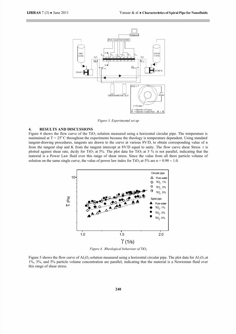
3. EXPERIMENTAL SET UP
The experimental set up is divided for two experimental. First experiment is shown in Fig. 1 The nanofluid are
circulated by piston pump and collected in tank. Flowing of nanofluid is compressed by compressor. The pressure
drop gradient is measured at 800 mm length between each pressure tap by manometer through a settling bottle. The
diameter of pressure hole is 1.2 mm and the flow rate is measured by a weighing machine in period of time. The
inner diameter of test circular pipe D is 10 mm. The shear stress and the shear rate can be obtained by measuring the
pressure drop gradient and the gradient of velocity, respectively. The nanopartiles used in this study are titanium
oxide (TiO2) and alumina (Al2O3) in which they are the most common and inexpensive nanoparticles used by manyresearchers in their experimental investigations. TiO2 and Al2O3 nanoparticles are in form of aqueous suspensions,
both at a concentration of particle volume 1%, 3% and 5%. The average size of TiO2 and Al2O3 particles estimate by
optical characterization techniques was about 21 nm and 13 nm, respectively. The nanoparticles are first diluted in
deionized water to an appropriate concentration and then ultrasonicated for 30 minutes. The temperature is keep at
25 oC.
The second experimental setup consists of spiral heat exchanger, thermocouple, manometer, pumps and tanks as
shown in Fig. 3 The hot fluid pipe is installed at the center core of the spiral pipe. The hot fluid is heated by water
heater and connected to tank having a capacity 30 litres. The cold fluid is made from nanoparticles solution that is
Al2O3, TiO2 and CuO with 1% and 3% concentration. Reciprocating pump is using to circulating cold fluid and hot
fluid. To measure the wall temperature of the copper tube and the mean temperature of the fluids at the inlet, six
thermocouples (T-type) are soldered on at different places along the test section and one thermocouple (T-type) is
inserted at the inlet of the test section. The pressure at both ends of test section is measured by a pressure transducer
that records the pressure drop due to the nanofluids. Nanofluids used in this study are water-based nanofluids withvarious volume fractions ranging from 1% to 3%. Nanofluids are used as the cold fluids and the water as the hot
fluid. The inlet hot fluid flow rate is kept constant and the inlet cold fluid flow rate is varied using a control valve.
The different cold fluid flow rate the temperatures at the inlet and outlet of hot and cold fluids are recorded, after
achieving the steady state. The some procedure is repeated for different hot fluid flow rates and the data related to
temperatures the corresponding temperatures and mass flow rates are recorded. The diameter of pressure hole was 2
mm and the flow rate was measured by a weighing machine in period of time.
hu
g
L
D f
2
2

8/12/2019 IJRRAS_7_3_03-IM1
http://slidepdf.com/reader/full/ijrras7303-im1 4/13
IJRRAS 7 (3) ● June 2011 Yanuar & al ● Characteristics of Spiral Pipe for Nanofluids
239
Figure 1. Experimental set up
Table 1. Dimension of spiral pipe
Pipe Di (mm) Do (mm) Δ d (mm) Pitch/Di
Spiral pipe 12 16 2 ± 7
Figure 2. Shape of tested spiral pipe
The dimension of the tested spiral pipes are given in Table 1. Cross-sectional diagram and the side views are shown
in Fig 2.
8/12/2019 IJRRAS_7_3_03-IM1
http://slidepdf.com/reader/full/ijrras7303-im1 5/13
IJRRAS 7 (3) ● June 2011 Yanuar & al ● Characteristics of Spiral Pipe for Nanofluids
240
Figure 3. Experimental set up
4. RESULTS AND DISCUSSIONS
Figure 4 shows the flow curve of the TiO2 solution measured using a horizontal circular pipe. The temperature is
maintained at T = 25o C throughout the experiments because the rheology is temperature dependent. Using standard
tangent-drawing procedures, tangents are drawn to the curve at various 8V/D, to obtain corresponding value of n
from the tangent slop and K from the tangent intercept at 8V/D equal to unity. The flow curve shear Stress is
plotted against shear rate, du/dy for TiO2 at 5%. The plot data for TiO2 at 5 % is not parallel, indicating that the
material is a Power Law fluid over this range of shear stress. Since the value from all there particle volume of
solution on the same single curve, the value of power law index for TiO 2 at 5% are n = 0.90 1.0.
1.0 1.5 2.0
10
Spiral pipe
Circular pipe
Pure water
TiO2, 1%
TiO2, 3%
TiO2, 5%
Pure water
TiO2, 1%
TiO2, 3%
TiO2, 5%
( P a )
(1/s)
Figure 4. Rheological behaviour of TiO2
Figure 5 shows the flow curve of Al2O3 solution measured using a horizontal circular pipe. The plot data for Al 2O3 at
1%, 3%, and 5% particle volume concentration are parallel, indicating that the material is a Newtonian fluid over
this range of shear stress.

8/12/2019 IJRRAS_7_3_03-IM1
http://slidepdf.com/reader/full/ijrras7303-im1 6/13
IJRRAS 7 (3) ● June 2011 Yanuar & al ● Characteristics of Spiral Pipe for Nanofluids
241
1.0 1.5 2.0
10
Spiral pipe
Circular pipe
Pure water
Al2O
3, 1%
Al2O
3, 3%
Al2O
3, 5%
Pure water
Al2O
3, 1%
Al2O
3, 3%
Al2O
3, 5%
( P
a )
(1/s)
Figure 5. Rheological behaviour of Al 2O3
In figure 6 Measurement of the viscosity of nanofluid are carried out by horizontal pipe viscometer and the data ofTiO2 at 1 %, 3%, and 5% volume concentration of nanofluid, the solution are presented apparent viscosity versus
shear rate in figure 6. It can be seen that the viscosity increased with increasing volume concentration.
Measurements of viscosity depend on the type of viscometer and the hysteresis of the shear stress or shear rate may
be occurred. Because the viscosity of nanofluid is complicatedly depend on many parameters and the generalized
Reynolds numbers, Re*, was calculated using the apparent viscosity of nanofluid. In this study, the rheogram for
this TiO2 at 5% was based on the measured pressure drop data of tested circular pipe. This suggested that the
viscometric properties of TiO2 at 5% vary in the low shear rate region. Accordingly, it can be considered that the
rheological behavior in the low shear rate is that of non-Newtonian fluids.
1.0 1.2 1.4 1.6 1.8 2.0 2.2
2x10⁻³
4x10⁻³
TiO2, 5%
TiO2, 3%
TiO2, 1%
Pure water
TiO2, 5%
TiO2, 3%
TiO2, 1%Pure water
Spiral pipe
Circular pipe
( P a s )
(1/s)
Figure 6. Apparent viscosity of TiO2
In figure 7 Measurement of the viscosity of nanofluid are carried out by horizontal pipe viscometer and the data of
Al2O3 at 1%, 3%, and 5% particle volume concentration of nanofluid, the solution are presented apparent viscosity
versus shear rate. The viscosities of Al2O3 are constant at the gradation of shear rate, which is newtonian fluid.

8/12/2019 IJRRAS_7_3_03-IM1
http://slidepdf.com/reader/full/ijrras7303-im1 7/13
IJRRAS 7 (3) ● June 2011 Yanuar & al ● Characteristics of Spiral Pipe for Nanofluids
242
1.0 1.2 1.4 1.6 1.8 2.0 2.2
2.0x10⁻³
4.0x10⁻³
6.0x10⁻³
Spiral pipe
Circular Pipe
Al2O
3, 5%
Al2O
3, 3%
Al2O
3, 1%
Pure water
Al2O
3, 5%
Al2O
3, 3%
Al2O
3, 1%
Pure water
( P a
s )
(1/s)
Figure 7. Apparent viscosity of Al 2O3
The experimentally determined coefficients of friction of nanofluid are shown in figure 8 and figure 9. The
experimental coefficient of friction results of TiO2 at 1%, 3% and 5% are shown in figure 8, dash line indicate the
analytical result of Hagen Pouiselle equation for laminar flow and the solid lines indicate the Blasius equation for
turbulent flow, f=0.3164 Re*-1/4. The coefficient of friction of TiO2 fit with the coefficient of friction of water for
circular pipe. Correlation for the coefficient of friction and Reynolds number can also be used by designers to more
accurately predict the pressure drop characteristics for nanofluid in circular pipe. Because the viscosity of nanofluid
is complicatedly dependent on many parameters, the Reynolds number regenerative is calculated using the apparent
viscosity of TiO2. The effect of nanofluid degradation on the result is examined by pipe friction coefficient
measurement.
103
104
105
10-1
SpiralCircular
TiO2, 1%
TiO2, 3%
TiO2, 5%
TiO2, 1%
TiO2, 3%
TiO2, 5%
f = 64/Re*
f = 0.3164*Re*̂ (1/4)
f
Re* Figure 8. Coefficient of friction of TiO2 for circular pipe D=3 mm
Figure 9 is coefficient of friction of Al2O3. The coefficient of friction of Al2O3 is slightly increased compared with
that of pure water, because an increase in friction coefficient is caused by suspension of nanoparticles in the pure
fluid. All Al2O3 data are located above the lines Blasius formula. Variation of particle volume concentration of
nanofluid has no effect on coefficient friction in the pipe.

8/12/2019 IJRRAS_7_3_03-IM1
http://slidepdf.com/reader/full/ijrras7303-im1 8/13
IJRRAS 7 (3) ● June 2011 Yanuar & al ● Characteristics of Spiral Pipe for Nanofluids
243
103
104
105
10-1
Spiral pipeCircular pipe
Al2O
3, 1%
Al2O
3, 3%
Al2O
3, 5%
Al2O
3, 1%
Al2O
3, 3%
Al2
O3
, 5%
f = 64/Re*
f = 0.3164*Re*̂ (1/4)
f
Re*
Figure 9. Coefficient of friction of Al 2O3 for circular pipe D=3 mm
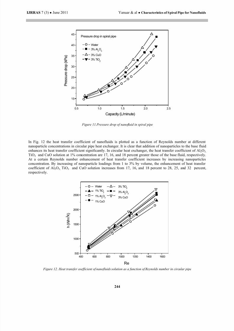
Figure 10 and 11 shows the pressure drop of Al 2O3, TiO2 and CuO solution measured by pressure transducer. The
pressure drop of the nanofluids is slightly increased compared with that of the pure water, because an increase in the
friction loss is caused by suspension of nanoparticles in the pure fluid. On the other hand, pressure drop of nano
fluids in spiral pipe are greater than in circular pipe. This phenomena is caused by swirling flow that result in spiral
pipe. The convective heat transfer coefficient of water-based Al2O3 nanofluids flowing through a circular tube for a
constant heat flux is experimentally measured to study convective heat transfer characteristics of water-based Al 2O3
nanofluids.
0.5 1.0 1.5 2.0 2.510
15
20
25
30
35
40
Pressure drop in circular pipe
P r e s s u r e d r o p ( k P a )
Capacity (L/minute)
Water
3% Al2O
3
3% CuO
3% TiO2
Figure 10. Pressure drop of nanofluids in circular pipe
8/12/2019 IJRRAS_7_3_03-IM1
http://slidepdf.com/reader/full/ijrras7303-im1 9/13
IJRRAS 7 (3) ● June 2011 Yanuar & al ● Characteristics of Spiral Pipe for Nanofluids
244
0.5 1.0 1.5 2.0 2.5
15
20
25
30
35
40
45Pressure drop in spiral pipe
P r e s s u r e d r o p ( k P a
)
Capacity (L/minute)
Water
3% Al2O
3
3% CuO
3% TiO2
Figure 11.Pressure drop of nanofluid in spiral pipe
In Fig. 12 the heat transfer coefficient of nanofluids is plotted as a function of Reynolds number at different
nanoparticle concentrations in circular pipe heat exchanger. It is clear that addition of nanoparticles to the base fluid
enhances its heat transfer coefficient significantly. In circular heat exchanger, the heat transfer coefficient of Al2O3,
TiO2 and CuO solution at 1% concentration are 17, 16, and 18 percent greater those of the base fluid, respectively.
At a certain Reynolds number enhancement of heat transfer coefficient increases by increasing nanoparticles
concentration. By increasing of nanoparticle loadings from 1 to 3% by volume, the enhancement of heat transfer
coefficient of Al2O3, TiO2 and CuO solution increases from 17, 16, and 18 percent to 28, 25, and 32 percent,
respectively.
400 600 800 1000 1200 1400 1600500
1000
1500
2000
2500
3% TiO2
3% Al2O
3
3% CuO
Water
1% TiO2
1% Al2O
3
1% CuO
h ( W / m 2 K )
Re
Figure 12. Heat transfer coefficient of nanofluids solution as a function of Reynolds number in circular pipe

8/12/2019 IJRRAS_7_3_03-IM1
http://slidepdf.com/reader/full/ijrras7303-im1 10/13
IJRRAS 7 (3) ● June 2011 Yanuar & al ● Characteristics of Spiral Pipe for Nanofluids
245
In Fig. 13 the heat transfer coefficient of nanofluids is plotted as a function of Reynolds number at different
nanoparticle concentrations in spiral pipe heat exchanger. Same as in circular pipe, in spiral pipe also occur
enhancement heat transfer coefficient for nanofluids. If we compare with circular pipe as shown in Fig. 14, heat
transfer coefficient of nanofluids and pure water are greater than in circular pipe. By using spiral pipe, the
enhancement of heat transfer coefficient of water, Al2O3, TiO2 and CuO solution are 7, 10, 11 and 10 percent greater
those of circular pipe, respectively. Enhancement of the effective thermal conductivity is an important factor that
causes the increases of the convective heat transfer coefficient on nanofluids. For spiral pipe heat exchanger, the
enhancement of heat transfer coefficient is caused by the thermal boundary layer thickness of spiral pipe is smaller
than circular pipe. Flow that occurred in spiral pipe as swirling flow so reducing the boundary layer thickness.
400 600 800 1000 1200 1400 1600500
1000
1500
2000
2500
3% TiO2
3% Al2O
3
3% CuO
Water
1% TiO2
1% Al2O
3
1% CuO
h ( W / m 2 K )
Re
Figure 13. Comparison heat transfer coefficient of nanofluids solution as a function of Reynolds number in spiral pipe
400 600 800 1000 1200 1400 1600
500
1000
1500
2000
2500
3000
3% CuO circular
3% TiO2 spiral
3% Al2O3 spiral3% CuO spiral
Water circular
Water spiral
3% TiO2
circular
3% Al2O
3 circular
h ( W / m 2 K )
Re
Figure 14. Comparison heat transfer coefficient of nanofluids solution as a function of Reynolds number in circular and spiral pipe
The local heat transfer coefficient of nanofluids as a function of axial distance from inlet of test section at different
nanoparticle concentrations in circular and spiral pipe at Reynolds number about 1500 was shown in fig. 15, 16, 17,
18 and 19. At a certain Reynolds number and nanoparticle concentrations the local heat transfer coefficient of
nanofluids decreases wtih increase in axial distance. This is due to the increasing boundary layer thickness with
increase in axial distance.

8/12/2019 IJRRAS_7_3_03-IM1
http://slidepdf.com/reader/full/ijrras7303-im1 11/13
IJRRAS 7 (3) ● June 2011 Yanuar & al ● Characteristics of Spiral Pipe for Nanofluids
246
0.0 0.2 0.4 0.6 0.8 1.02200
2400
2600
2800
3000
3200
3400
3600
h z
( W / m 2 K )
z/L
Al2O3, 1%, Circular
Al2O3, 1%, Spiral
Al2O3, 3%, Circular
Al2O3, 3%, Spiral
Figure 15. Local heat transfer coefficient of Al 2O3 as a function of axial distance from tube inlet.
0.0 0.2 0.4 0.6 0.8 1.0
2200
2400
2600
2800
3000
3200
3400
3600 CuO, 1 %, Circular
CuO, 1 %, Spiral
CuO, 3 %, Circular
CuO, 3 %, Spiral
h z
( W / m 2 K )
z/L
Figure 16. Local heat transfer coefficient of CuO as a function of axial distance from tube inlet.
0.0 0.2 0.4 0.6 0.8 1.02000
2200
2400
2600
2800
3000
3200
3400
3600
TiO2, 1 %, Circular
TiO2, 1 %, Spiral
TiO2, 3 %, Circular
TiO2, 3 %, Spiral
h z (
W / m 2 K )
z/L
Figure 17. Local heat transfer coefficient of TiO2 as a function of axial distance from tube inlet.

8/12/2019 IJRRAS_7_3_03-IM1
http://slidepdf.com/reader/full/ijrras7303-im1 12/13
IJRRAS 7 (3) ● June 2011 Yanuar & al ● Characteristics of Spiral Pipe for Nanofluids
247
0.0 0.2 0.4 0.6 0.8 1.0
2000
2200
2400
2600
2800
3000
3200
3400
3600
3800
4000
Re = 1500
3% Cu
3% Al2O
3
3% TiO2
1% Cu
1% Al2O
3
1% TiO2
Pure water
h z
( W / m 2 K )
z/L
Figure 18. Local heat transfer coefficient of CuO, Al 2O3 , TiO2 as a function of axial distance from tube inlet in
circular pipe.
0.0 0.2 0.4 0.6 0.8 1.01800
2000
2200
2400
2600
2800
3000
3200
3400
3600Re = 1500
3% Cu
3% Al2O
3
3% TiO2
1% Cu
1% Al2O
3
1% TiO2
Pure water
h z
( W / m
2 K )
z/L
Figure 19. Local Local heat transfer coefficient of CuO, Al 2O3 , TiO2 as a function of axial distance from tube inlet
in spiral pipe.
5. CONCLUSION
Experimental study has been performed to investigate enhancement of coefficient heat transfer, pressure drop that
occur with spiral pipe and nanoparticles. On the other hand, flow characteristic also experimented with capillary
pipe. The results are summarized follows:
(1) The TiO2 behaves as the Newtonian fluids for 1%, 3% and the shear thinning fluid (pseudoplastics fluid) for
5% particle volume consentration. The power law model describes approximately the behavior of TiO 2 and the
range of the power law fluids index is n = 0.90 1.0.

8/12/2019 IJRRAS_7_3_03-IM1
http://slidepdf.com/reader/full/ijrras7303-im1 13/13
IJRRAS 7 (3) ● June 2011 Yanuar & al ● Characteristics of Spiral Pipe for Nanofluids
248
(2) The relative viscosity of nanofluids increases with an
increase in concentration of nanoparticles.
(3) The Pressure drop of spiral pipe heat exchanger tends to increase slightly compared with circular pipe.
(4) The convective heat transfer coefficient of the nanofluids Al2O3 increases by up to 28% at a concentration of
3 vol. % compared with that of pure water.
(5) At a given Reynolds number and nanoparticle concentration the local heat transfer coefficient of nanofluids
as well as base fluid decreases with increasing axial distance from the inlet of the test section.
6. ACKNOWLEDGMENTThis work is supported by the Directorate for Research and Community Service, Directorate General of Higher
Education, Ministry of National Education 2010, Jakarta. Indonesia.
7. REFERENCES[1]. R.A. Seban, E. F. McLaughlin, Heat transfer in tube coils with laminar and turbulent flow, International
Journal of heat and Mass Transfer, 6, 1963, 387-395.
[2]. G.F.C. Rogers, Y.R. mayhew, Heat transfer and pressure loss in helkically coiled tubes with turbulent flow,
International Journal of Heat and Mass Transfer, 7, 1964, 1207-1216.
[3]. Y. Mori, W. Nakayama, Study on forced convective heat transfer in curved pipe. International Journal of heat
and Mass Transfer, 8, 1965, 67-82.
[4]. A Rao, et al. “Characterization of nanoparticles using Atomic Force Microscopy” Journal of
Physics:Conference Series 61 (2007) 971-976.[5]. S. U. S. Choi, “Enhancing thermal conductivity of fluids with nanoparticles,” in Developments
Applications of Non-Newtonian Flows, D. A. Siginer and H. P. Wang, Eds., FEDvol. 231/MD-vol. 66, pp.
99 – 105, ASME, New York, NY, USA, 1995.
[6]. Q. Li and Y. Xuan, “Convective heat transfer performances of fluids with nano- particles,” in Proceedings
of the 12th International Heat Transfer Conference, pp. 483 – 488, 2002.
[7]. Wen, D. & Ding, Y. 2004 Experimental investigation into convective heat transfer of nanofluid at the
entrance region under laminar flow conditions. Int. J. Heat Mass Transfer, Vol. 47, pp. 5181-5188.
[8]. Yang, Y., Zhang, Z.G., Grulke, E.A., Anderson, W.B. & Wu, G. 2005 Heat transfer properties of
nanoparticle-in-fluid dispersions (nanofluids) in laminar flow. Int. J. Heat Mass Transfer, Vol. 48, pp. 1107-
1116.
[9]. Kyo Sik Hwang, Seok Pil Jang, Stephen U S Choi. “Flow and Convective Heat Transfer Characteristics of
Water-based Al2O
3 Nanofluids in Fully Developed Laminar Flow Regime” 7th JSME-KSME Thermal and
Fluids Engineering Conference. C311. Oct 13-16, 2008, Saporo, Japan.
[10]. Yanuar, et al. “Hydraulics conveyances of mud slurry by a spiral pipe” Journal of Mechanical Science and
Technology 23 (2009) 1835 – 1839.
[11]. Yanuar, N Putra, Gunawan, and M Baqi “Rheological Properties of Nanofluid in a circular Pipe.
International conference on heat transfer, fluid mechanics and thermodynamics. HEFAT 2010 19 -21 July
2010 Antalya, Turkey


![T-76.115 Project Review RoadRunners [IM1] Iteration 02.12.2003](https://img.pdfslide.us/doc/110x75/56649f3e5503460f94c5e794/t-76115-project-review-roadrunners-im1-iteration-02122003.jpg)


