Embed Size (px)
Citation preview

IGBT parallelingZhou Yizheng
Set date Page 2Copyright © Infineon Technologies 2010. All rights reserved.
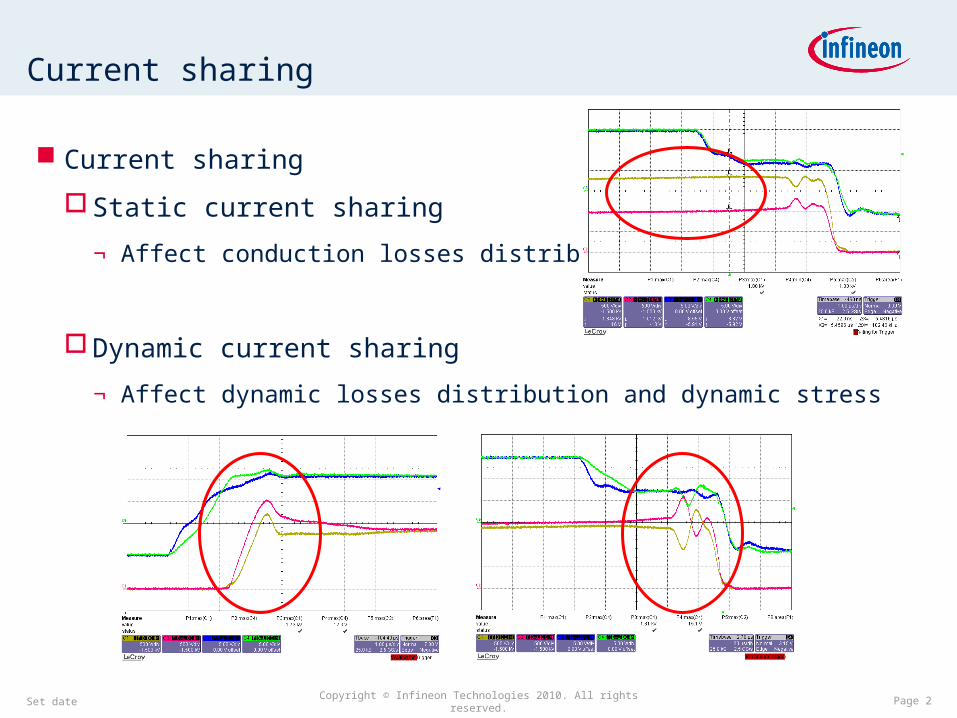
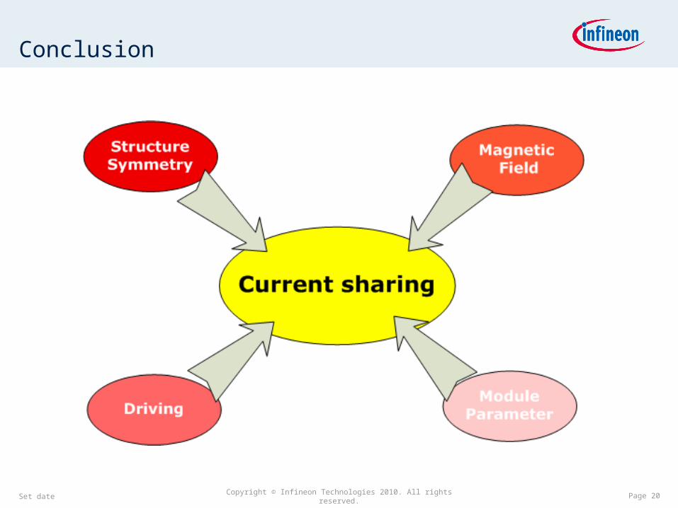
Current sharing
Current sharing
Static current sharing
¬ Affect conduction losses distribution
Dynamic current sharing
¬ Affect dynamic losses distribution and dynamic stress
Set date Page 3Copyright © Infineon Technologies 2010. All rights reserved.
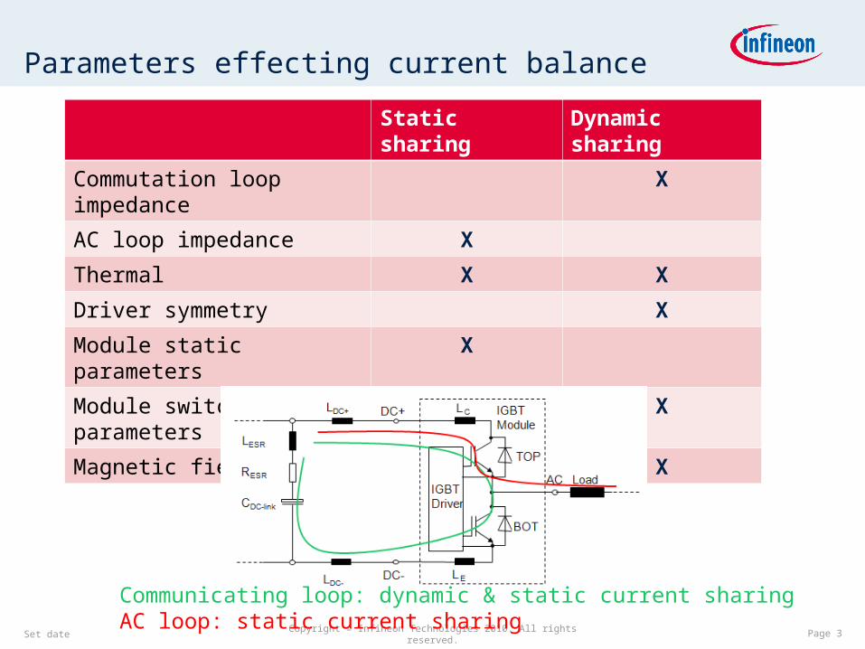
Parameters effecting current balance
Static sharing Dynamic sharing
Commutation loop impedance X
AC loop impedance X
Thermal X X
Driver symmetry X
Module static parameters X
Module switching parameters X
Magnetic field X
Communicating loop: dynamic & static current sharingAC loop: static current sharing
Set date Page 4Copyright © Infineon Technologies 2010. All rights reserved.
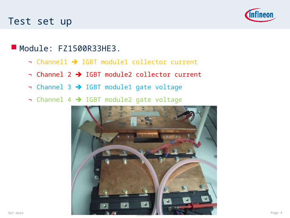
Test set up
Module: FZ1500R33HE3.
¬ Channel1 IGBT module1 collector current
¬ Channel 2 IGBT module2 collector current
¬ Channel 3 IGBT module1 gate voltage
¬ Channel 4 IGBT module2 gate voltage
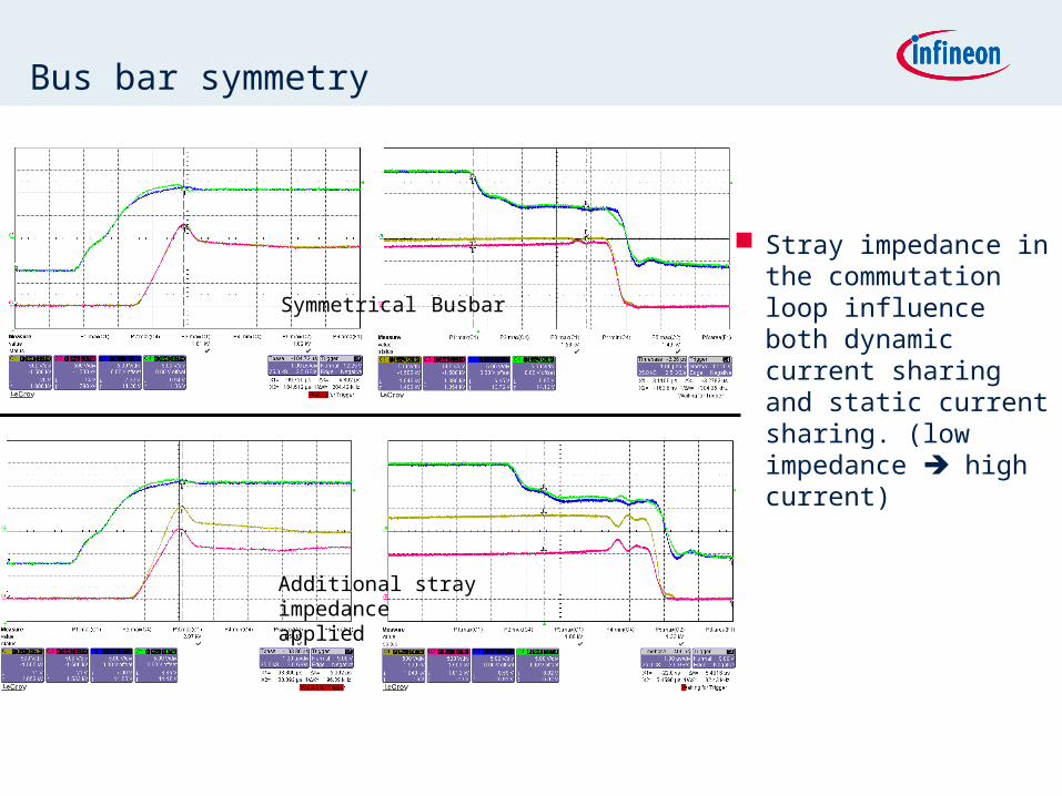
Bus bar symmetry
Stray impedance in the commutation loop influence both dynamic current sharing and static current sharing. (low impedance high current)
Symmetrical Busbar
Additional stray impedance applied
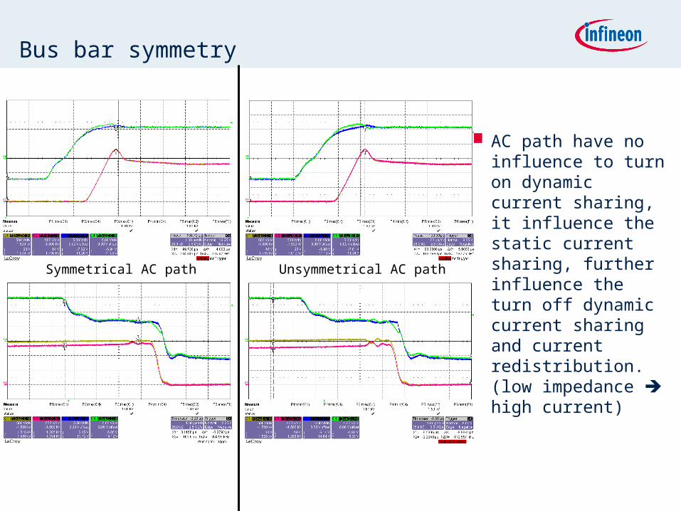
Bus bar symmetry
AC path have no influence to turn on dynamic current sharing, it influence the static current sharing, further influence the turn off dynamic current sharing and current redistribution. (low impedance high current)
Symmetrical AC path Unsymmetrical AC path
Bus bar symmetry
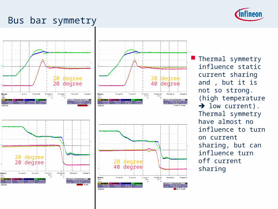
Thermal symmetry influence static current sharing and , but it is not so strong. (high temperature low current). Thermal symmetry have almost no influence to turn on current sharing, but can influence turn off current sharing20 degree
20 degree
20 degree20 degree
20 degree40 degree
20 degree40 degree
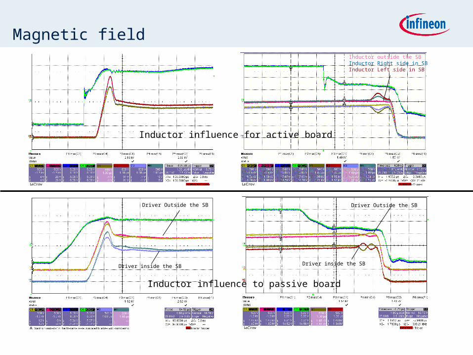
Inductor outside the SBInductor Right side in SBInductor Left side in SB
Magnetic field
Driver Outside the SB
Driver inside the SB
Driver Outside the SB
Driver inside the SB
Inductor influence for active board
Inductor influence to passive board
Magnetic field
For FZ+FZ double pulse test setup:
Cable connection inside bus bar influence both static current sharing and current redistribution(created magnetic field influence bus bar impedance), but almost no influence at turn on.
Magnetic filed of inductor can influence current redistribution and driver (if the driver is passive adaptor board based) further influence turn on current sharing and current redistribution.
If active adaptor board based driver is used, magnetic filed of inductor have almost no influence on turn on current sharing
Set date Page 10Copyright © Infineon Technologies 2010. All rights reserved.
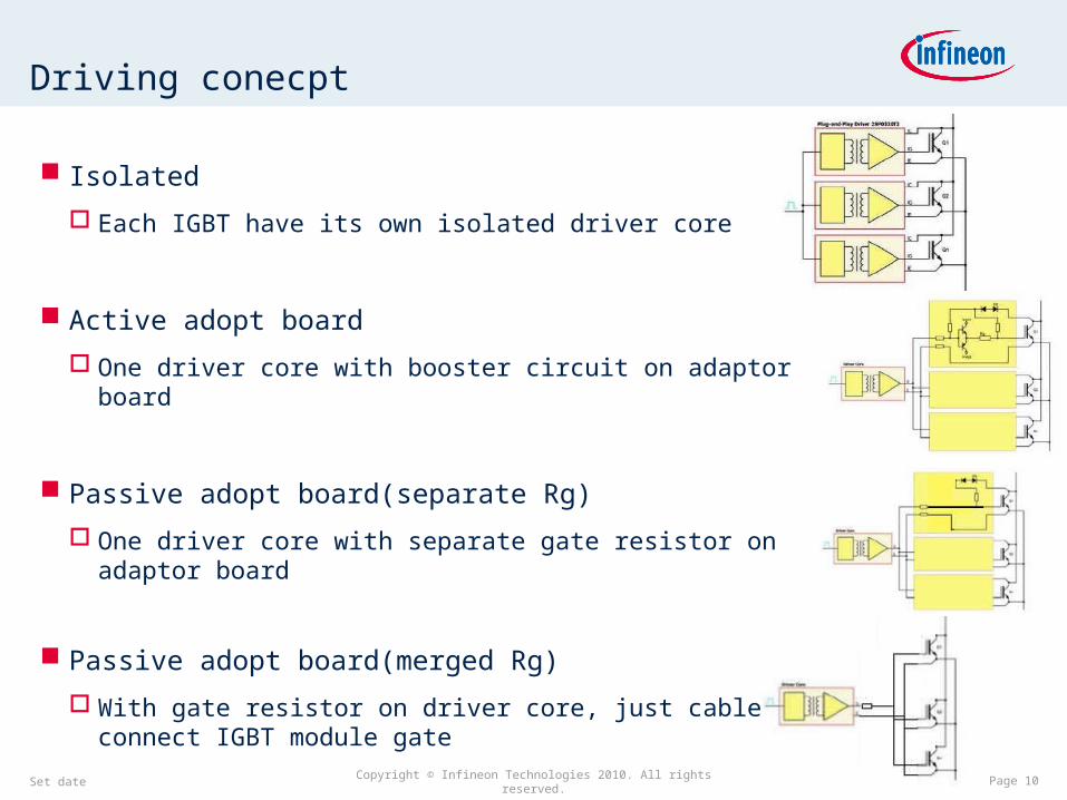
Driving conecpt
Isolated
Each IGBT have its own isolated driver core
Active adopt board
One driver core with booster circuit on adaptor board
Passive adopt board(separate Rg)
One driver core with separate gate resistor on adaptor board
Passive adopt board(merged Rg)
With gate resistor on driver core, just cable to connect IGBT module gate
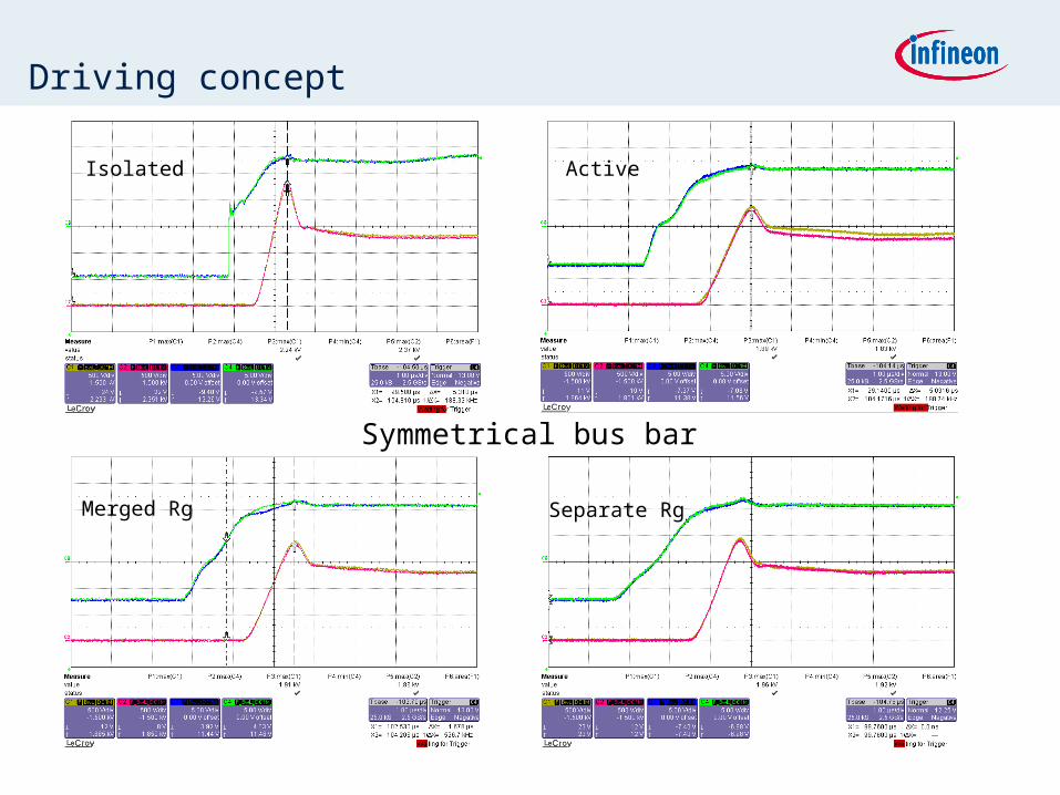
Driving concept
Isolated Active
Merged Rg Separate Rg
Symmetrical bus bar
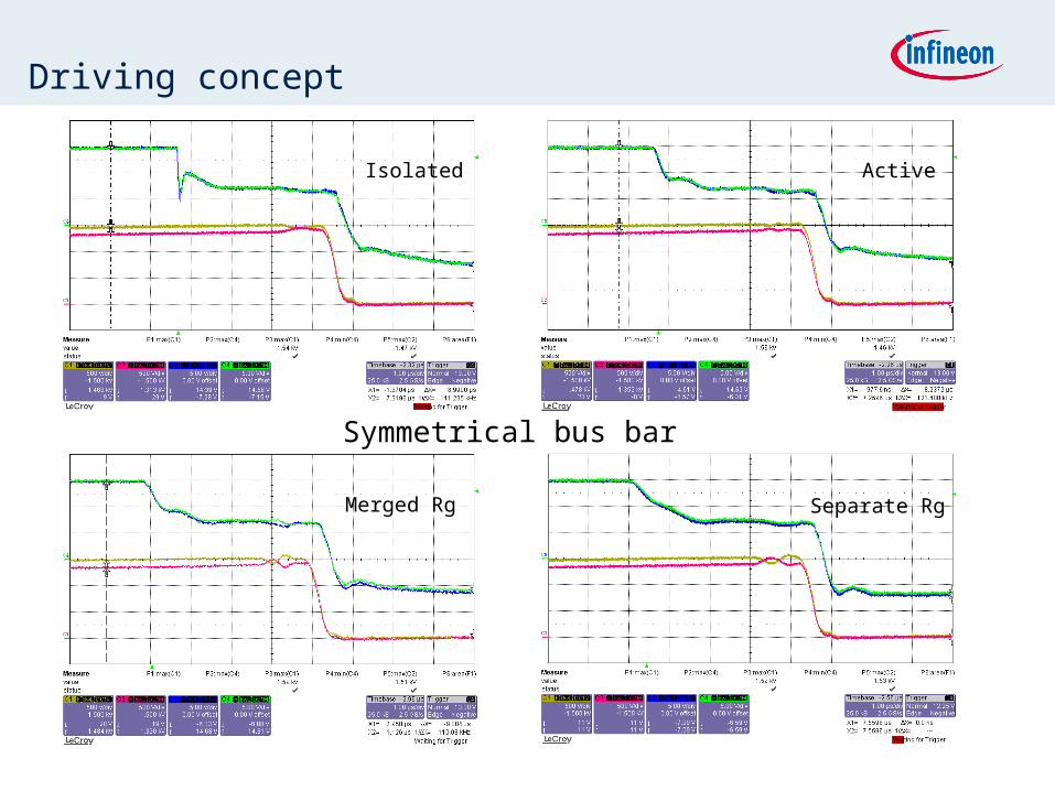
Driving concept
Isolated Active
Merged Rg Separate Rg
Symmetrical bus bar
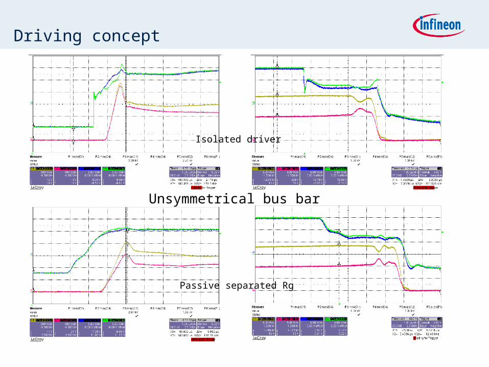
Driving concept
Isolated driver
Passive separated Rg
Unsymmetrical bus bar
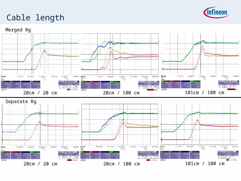
Cable lengthMerged Rg
Separate Rg
20cm / 20 cm 20cm / 100 cm 101cm / 100 cm
20cm / 20 cm 20cm / 100 cm 101cm / 100 cm
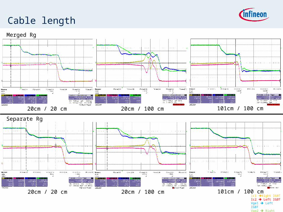
Cable length
Separate Rg
Merged Rg
20cm / 20 cm 20cm / 100 cm 101cm / 100 cm
20cm / 20 cm 20cm / 100 cm 101cm / 100 cmIc1 Right IGBTIc2 Left IGBTVge1 Left IGBTVge2 Right IGBT
Driving
Different driver concept shows almost similar turn on/off performance, at precondition that system is symmetry.
Active board shows a little bit poorer turn on current sharing performance
Passive board shows high amplitude of current redistribution and oscillation frequency
In unsymmetrical system, isolated driver shows better turn on dynamic current sharing and almost similar turn off dynamic current sharing.
Separate Rg shows better dynamic current sharing than merged Rg, if gate cable is unsymmetrical.
Set date Page 17Copyright © Infineon Technologies 2010. All rights reserved.
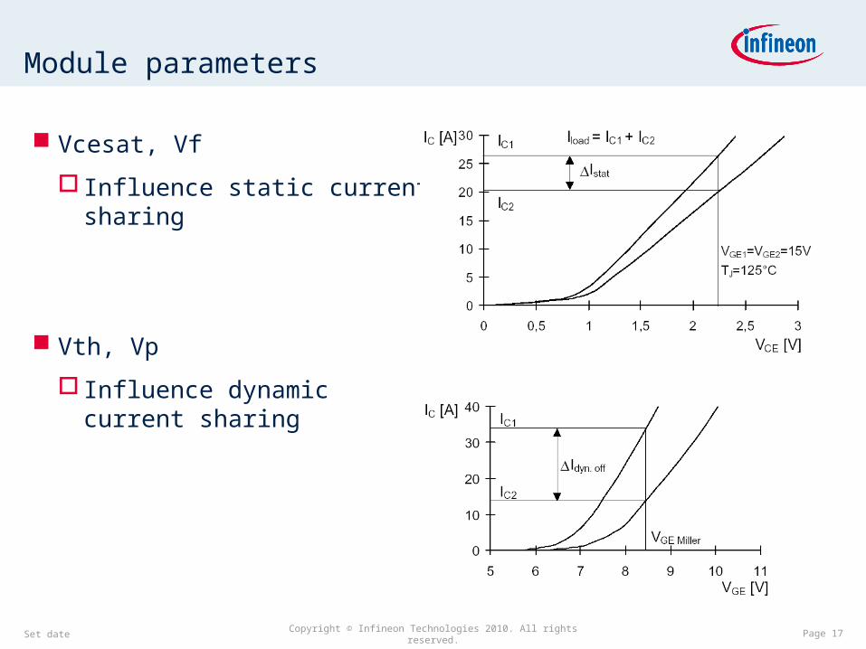
Module parameters
Vcesat, Vf
Influence static current sharing
Vth, Vp
Influence dynamic current sharing
Set date Copyright © Infineon Technologies 2010. All rights reserved. Page 18
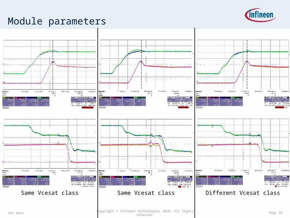
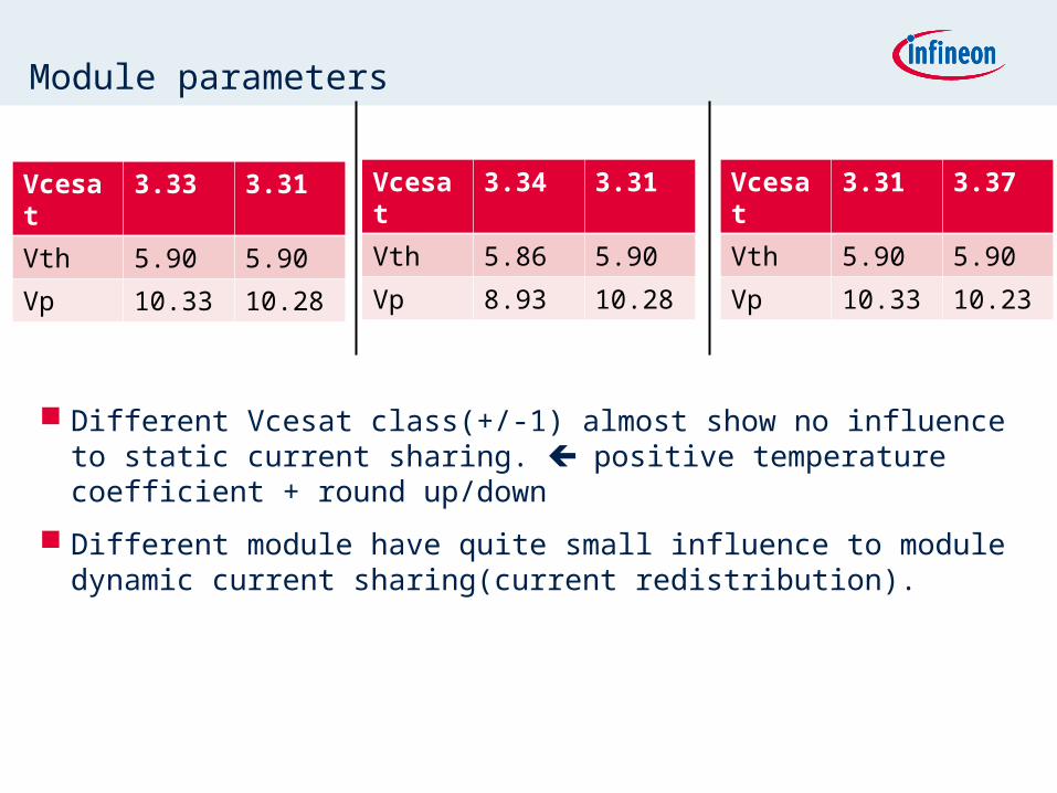
Module parameters
Same Vcesat class Same Vcesat class Different Vcesat class
Module parameters
Different Vcesat class(+/-1) almost show no influence to static current sharing. positive temperature coefficient + round up/down
Different module have quite small influence to module dynamic current sharing(current redistribution).
Vcesat 3.33 3.31
Vth 5.90 5.90
Vp 10.33 10.28
Vcesat 3.34 3.31
Vth 5.86 5.90
Vp 8.93 10.28
Vcesat 3.31 3.37
Vth 5.90 5.90
Vp 10.33 10.23
Set date Page 20Copyright © Infineon Technologies 2010. All rights reserved.
Conclusion
Conclusion
System symmetry is at first priority (including commutation loop symmetry, AC path symmetry and AC output cable position).
Based on symmetrical system, either isolated driver or active adaptor board or passive adaptor board all can get very good current sharing results.
If cable length for passive adaptor is not same, separated Rg and emitter Rg is recommended.
Module influence to current sharing is quite small. IGBT Vcesat class +/-1 is quite Ok for current sharing. It’s better to take same Vf class module.
System magnetic field effect need to be care about