Embed Size (px)
Citation preview

ACHIEVING HIGHER DEPENDABILITY THROUGHHOST AND NIC PROCESSOR COLLABORATION
A Dissertation Presented
by
YIZHENG ZHOU
Submitted to the Graduate School of theUniversity of Massachusetts Amherst in partial fulfillment
of the requirements for the degree of
DOCTOR OF PHILOSOPHY
September 2008
Electrical and Computer Engineering

3336931
3336931 2009

c© Copyright by Yizheng Zhou 2008
All Rights Reserved

ACHIEVING HIGHER DEPENDABILITY THROUGHHOST AND NIC PROCESSOR COLLABORATION
A Dissertation Presented
by
YIZHENG ZHOU
Approved as to style and content by:
Israel Koren, Chair
C. Mani Krishna, Member
Tilman Wolf, Member
Charles C. Weems, Member
Christopher V. Hollot, Department HeadElectrical and Computer Engineering

ABSTRACT
ACHIEVING HIGHER DEPENDABILITY THROUGHHOST AND NIC PROCESSOR COLLABORATION
SEPTEMBER 2008
YIZHENG ZHOU
B.Sc., TSINGHUA UNIVERSITY
M.Sc., NORTH CAROLINA STATE UNIVERSITY
Ph.D., UNIVERSITY OF MASSACHUSETTS AMHERST
Directed by: Professor Israel Koren
Traditionally, distributed systems requiring high dependability were designed us-
ing custom hardware with massive amounts of redundancy. Not only the nodes, but
the network, was replicated in most of these systems. Recently, the need for cost
reduction and access to the latest commercial technologies has prompted the use of
commercial off-the-shelf (COTS) hardware and software products in the design of
such systems. On the other hand, reliance on COTS technology brings about new
challenges in system reliability. This dissertation attempts to address these challenges
by developing fault tolerance techniques for modern high-speed networking-based sys-
tems.
Being driven by the demand for greater network performance, emerging network
technologies have complex network interfaces with a Network Interface Card (NIC)
iv

processor and large local memory. However, increasing complexity results in a larger
set of failure points and a potential increase in the network failure rate. This is in
addition to the system failures that can be caused by faults that strike the host system.
In this dissertation, we propose to achieve higher dependability of distributed systems
through host and NIC processor collaboration. The host processor will detect and
recover a failed network interface, and in addition, the symbiotic relationship allows
the NIC processor to aid in the recovery of a failed host system or application. More
specifically, we present an effective low-overhead adaptive and concurrent self-testing
technique to protect programmable high-speed network interfaces, and a low-overhead
message logging protocols to achieve fast recovery from host application crashes.
v

TABLE OF CONTENTS
Page
ABSTRACT . . . . . . . . . . . . . . . . . . . . . . . . . . . . . . . . . . . . . . . . . . . . . . . . . . . . . . . . . . iv
LIST OF TABLES . . . . . . . . . . . . . . . . . . . . . . . . . . . . . . . . . . . . . . . . . . . . . . . . . . .viii
LIST OF FIGURES . . . . . . . . . . . . . . . . . . . . . . . . . . . . . . . . . . . . . . . . . . . . . . . . . . . ix
CHAPTER
1. INTRODUCTION . . . . . . . . . . . . . . . . . . . . . . . . . . . . . . . . . . . . . . . . . . . . . . . . . 1
1.1 COTS Products . . . . . . . . . . . . . . . . . . . . . . . . . . . . . . . . . . . . . . . . . . . . . . . . . . 11.2 Single Event Upset . . . . . . . . . . . . . . . . . . . . . . . . . . . . . . . . . . . . . . . . . . . . . . . 31.3 Research Goals . . . . . . . . . . . . . . . . . . . . . . . . . . . . . . . . . . . . . . . . . . . . . . . . . . . 41.4 Previous Work . . . . . . . . . . . . . . . . . . . . . . . . . . . . . . . . . . . . . . . . . . . . . . . . . . . 61.5 Contribution of the Dissertation . . . . . . . . . . . . . . . . . . . . . . . . . . . . . . . . . . . . 71.6 Organization of the Dissertation . . . . . . . . . . . . . . . . . . . . . . . . . . . . . . . . . . . . 8
2. ADAPTIVE AND CONCURRENT SELF-TESTING . . . . . . . . . . . . . . 9
2.1 Related Work . . . . . . . . . . . . . . . . . . . . . . . . . . . . . . . . . . . . . . . . . . . . . . . . . . . 112.2 Myrinet: An Example Programmable Network Interface . . . . . . . . . . . . . . 12
2.2.1 Myrinet NIC . . . . . . . . . . . . . . . . . . . . . . . . . . . . . . . . . . . . . . . . . . . . . 132.2.2 Myrinet Software . . . . . . . . . . . . . . . . . . . . . . . . . . . . . . . . . . . . . . . . . . 13
2.3 Failure Detection . . . . . . . . . . . . . . . . . . . . . . . . . . . . . . . . . . . . . . . . . . . . . . . . 16
2.3.1 Failure Detection Strategy . . . . . . . . . . . . . . . . . . . . . . . . . . . . . . . . . . 172.3.2 Implementation . . . . . . . . . . . . . . . . . . . . . . . . . . . . . . . . . . . . . . . . . . . 21
2.4 Experimental Results . . . . . . . . . . . . . . . . . . . . . . . . . . . . . . . . . . . . . . . . . . . . 23
2.4.1 Failure Coverage . . . . . . . . . . . . . . . . . . . . . . . . . . . . . . . . . . . . . . . . . . 232.4.2 Performance Impact . . . . . . . . . . . . . . . . . . . . . . . . . . . . . . . . . . . . . . . 27
vi

3. PROGRAMMABLE-NIC-ASSISTED MESSAGE LOGGING . . . . . 30
3.1 System Model and Assumptions . . . . . . . . . . . . . . . . . . . . . . . . . . . . . . . . . . . 323.2 Message Logging Protocols . . . . . . . . . . . . . . . . . . . . . . . . . . . . . . . . . . . . . . . . 343.3 Programmable-NIC-Assisted Message Logging . . . . . . . . . . . . . . . . . . . . . . . 37
3.3.1 The Coordination During Failure-Free Execution . . . . . . . . . . . . . . 393.3.2 Failure Recovery . . . . . . . . . . . . . . . . . . . . . . . . . . . . . . . . . . . . . . . . . . 44
3.4 Implementation Issues . . . . . . . . . . . . . . . . . . . . . . . . . . . . . . . . . . . . . . . . . . . . 46
3.4.1 IXP1200-based Board and Programmable NIC . . . . . . . . . . . . . . . . 473.4.2 The MPICH-V framework and the Berkeley Lab
Checkpoint/Restart . . . . . . . . . . . . . . . . . . . . . . . . . . . . . . . . . . . . 483.4.3 Implementation Issues of NMLP . . . . . . . . . . . . . . . . . . . . . . . . . . . . 52
3.5 Performance Evaluation . . . . . . . . . . . . . . . . . . . . . . . . . . . . . . . . . . . . . . . . . . 55
3.5.1 Raw Communication Performance . . . . . . . . . . . . . . . . . . . . . . . . . . . 563.5.2 The NAS Parallel Benchmark . . . . . . . . . . . . . . . . . . . . . . . . . . . . . . . 56
4. SUMMARY AND FUTURE WORK . . . . . . . . . . . . . . . . . . . . . . . . . . . . . . 62
BIBLIOGRAPHY . . . . . . . . . . . . . . . . . . . . . . . . . . . . . . . . . . . . . . . . . . . . . . . . . . . 66
vii

LIST OF TABLES
Table Page
2.1 Results of Fault Injection. . . . . . . . . . . . . . . . . . . . . . . . . . . . . . . . . . . . . . . . . 25
viii
LIST OF FIGURES
Figure Page
1.1 The Fault Tolerance Architecture. . . . . . . . . . . . . . . . . . . . . . . . . . . . . . . . . . . 5
2.1 Example Myrinet Network. . . . . . . . . . . . . . . . . . . . . . . . . . . . . . . . . . . . . . . . 12
2.2 Simplified block diagram of the Myrinet NIC. . . . . . . . . . . . . . . . . . . . . . . . 13
2.3 Simplified View of the Myrinet Control Program (MCP). . . . . . . . . . . . . . 14
2.4 Examples of Fault Effects on Myrinet’s GM. . . . . . . . . . . . . . . . . . . . . . . . . 16
2.5 Logical Modules and Routines. . . . . . . . . . . . . . . . . . . . . . . . . . . . . . . . . . . . . 19
2.6 Data Flow of Self-Testing. . . . . . . . . . . . . . . . . . . . . . . . . . . . . . . . . . . . . . . . . 20
2.7 Comparison of the Original GM and FDGM. . . . . . . . . . . . . . . . . . . . . . . . . 28
2.8 Performance Impact for Different Self-Testing Intervals. . . . . . . . . . . . . . . . 28
3.1 System Architecture. . . . . . . . . . . . . . . . . . . . . . . . . . . . . . . . . . . . . . . . . . . . . . 38
3.2 The Coordination During Failure-Free Execution. . . . . . . . . . . . . . . . . . . . . 40
3.3 An application process fails with no checkpointing running. . . . . . . . . . . . 44
3.4 An application process fails during checkpointing. . . . . . . . . . . . . . . . . . . . . 45
3.5 Simplified block diagram of the IXP1200-based RadiSys ENP2505board. . . . . . . . . . . . . . . . . . . . . . . . . . . . . . . . . . . . . . . . . . . . . . . . . . . . . . . 46
3.6 Simplified block diagram of the NIC software. . . . . . . . . . . . . . . . . . . . . . . . 48
3.7 General architecture of MPICH and the MPICH-V framework. . . . . . . . . 49
3.8 Packet encapsulations in the MPICH-V framework . . . . . . . . . . . . . . . . . . . 51
ix

3.9 Latency of rollback recovery protocols . . . . . . . . . . . . . . . . . . . . . . . . . . . . . . 57
3.10 Latency difference between message logging protocols and thecoordinated checkpointing (VCL) . . . . . . . . . . . . . . . . . . . . . . . . . . . . . . . 57
3.11 Bandwidth of rollback recovery protocols . . . . . . . . . . . . . . . . . . . . . . . . . . . 58
3.12 Bandwidth difference between message logging protocols and thecoordinated checkpointing (VCL) . . . . . . . . . . . . . . . . . . . . . . . . . . . . . . . 58
3.13 Performance comparison of protocols for NPB Class W . . . . . . . . . . . . . . . 59
3.14 Performance comparison of protocols for NPB Class A . . . . . . . . . . . . . . . . 59
x

CHAPTER 1
INTRODUCTION
Historically, designers of distributed systems developed custom hardware and/or
software with massive amounts of redundancy to improve system dependability. Due
to development cost and time constraints, traditional solutions are now giving way to
designs based on Commercial Off-The-Shelf (COTS) hardware and software products.
The increased reliance on COTS technology has created a growing need for lightweight
fault tolerance. This dissertation attempts to address this problem for modern COTS-
based distributed systems.
1.1 COTS Products
COTS products software and hardware components that already exist and are
available to the general public. The use of COTS is often an alternative to in-
house development or one-time development. Over the past decade, the use of COTS
products as elements of distributed systems has become increasingly commonplace,
due to the expected lower cost and faster system construction. Organizations that
adopt a COTS-based systems approach also expect to stay in step with the advances
in commercial technologies that occur in the competitive marketplace.
The pros in using COTS products are [29]:
• Functionality is ready and available. COTS products come as ready-made and
ready-to-use applications. There is no need to “reinvent the wheel.”
1

• Functionality is tested and working. COTS products have undergone a consid-
erable amount of testing through a dedicated team. Also, they have been used
by a large community of users and experts.
• Functionality is rich. Since system requirements are derived in the narrow
confines of a specific problem domain, COTS products may offer greater func-
tionality not previously considered.
• Support is available. Maintenance is provided by the vendor or available in the
market place, and the cost is usually a fraction of doing it in-house. Also, using
COTS allows one to avail of upgrades of the product and keep current with
advances in technology.
There are cons, as well in using COTS products [29]:
• No control over the requirements for the COTS. Requirements are subject to
market forces, therefore, the COTS components may not address all of the
product requirements. Additional effort may be needed to meet reliability,
security, and safety requirements to protect against COTS vulnerability.
• No control over the quality of the COTS. The quality of COTS products, doc-
umentation, and support are in the hands of vendors.
• Learning curve. Although COTS products offer ready-made functionality, de-
velopers have to become familiar with it before being able to use it.
The advantages of COTS products, in fact, outweigh the disadvantages. But as
mentioned above, no COTS products have been designed to meet one’s unique set
of requirements, and as a result there will be a gap between the requirements and
those met by the COTS products. Developers must understand this problem well
before the implementation and ensure that the COTS products can be customized
and modified to fix the gap.
2

1.2 Single Event Upset
The use of COTS products in mission-critical applications is a growing trend,
mainly due to development cost and time constraints. However, COTS products are
not usually designed to meet the stringent requirements of mission-critical applica-
tions. Furthermore, as a consequence of the technological progress in microelectronics,
COTS-based systems become increasingly sensitive to different effects of the environ-
ment. Particularly, COTS hardware components used in space are susceptible to
transient faults due to Single Event Upsets (SEU).
SEUs have emerged as a key challenge in the design of COTS-based systems
for critical applications even at ground level. SEUs arise from energetic particles,
such as neutrons from cosmic rays and alpha particles from packaging material. As
energetic particles pass through a semiconductor device, they lose energy by ionizing
the medium and generate electron-hole pairs. These charges accumulate in transistor
source and diffusion nodes. A sufficient amount of charges may introduce a fault into
circuit operations, such as transient pulses in logic or support circuitry, or bit flips in
memory cells or registers [55]. Because this type of events are non-destructive, it is
termed soft or transient. Typically, a reset of the device or a rewriting of the memory
cell results in normal device behavior thereafter.
As transistor counts continue to increase exponentially, SEUs will be an increasing
burden for COTS-based system designers. The raw error rate per SRAM or latch bit
is projected to be roughly constant or slightly decrease for the next several technology
generations [21, 24]. This means that a COTS-based system’s error rate will grow in
direct proportion to the complexity of COTS components in each succeeding gener-
ation, unless we strengthen the COTS products used in mission-critical applications
with specific fault tolerance techniques.
3

1.3 Research Goals
This dissertation attempts to address the challenges raised by the use of COTS
components and the occurrence SEUs by developing fault tolerance techniques for
modern high-speed networking-based distributed systems. Although numerous fault
tolerance techniques have been developed to improve the reliability of distributed sys-
tems, as far as we know, none of them take advantage of modern network interfaces
that include a NIC processor and large local memory. In this dissertation, our objec-
tive is to take advantage of a collaboration between the host processor and the NIC
processor to develop fault tolerant techniques that will allow the system to quickly
recover from failures without a significant penalty in performance.
Networking hardware has made big strides over the past decade in both perfor-
mance and cost efficiency. Many modern network interfaces have in common a dedi-
cated processor that relieves the host processor of networking chores such as packet
creation, packet scheduling and ensuring in-order delivery of messages. Most of these
networking technologies are I/O attached (i.e., the internal connection is from the
I/O bus rather than from memory) and message-based (i.e., communications take
place through explicit messages rather than through shared storage). Examples of
such technology include Myrinet, Infiniband, Gigabit Ethernet and IBM PowerNP.
While a NIC processor is typically meant to aid in networking functions, it can ad-
vantageously aid in fault tolerance as well.
Our fault tolerance techniques exploit the co-existence of the host processor and
the NIC processor in a symbiotic relationship to achieve a better fault tolerant sys-
tem. The host processor will detect and recover a failed network interface and the
NIC processor will aid the failure detection and recovery of a failed host system or
application. Though a dual-processor mechanism for fault detection has been pro-
posed and used earlier, it involved complete duplication of functionality. In our case,
the degree of autonomy between the network NIC and the host processor allows the
4

H o s t H o s t
N I C N I C
I n t e r c o n n e c t i o n N e t w o r k
A p p l i c a t i o nP r o c e s s
H o s t F TE l e m e n t
N e t w o r k F TE l e m e n t
Figure 1.1. The Fault Tolerance Architecture.
two to carry out their very own functions, while still being able to provide the fault
tolerance functionality.
We propose a layered fault tolerance architecture that is composed of two fault
tolerance elements, one in the host system and the other in the network interface, as
shown in Figure 1.1. Each element keeps track of the health of the other and takes a
corrective action upon a failure. Such an approach takes advantage of the autonomy
between the host system and the I/O attached network interface, thus a fault that
typically affects the host system, if taken care of quickly, will not affect the network
interface and vice-versa. In this dissertation, we investigate how to improve system
reliability with minimal performance overhead through the proposed fault tolerance
architecture.
5

1.4 Previous Work
Lakamraju has successfully implemented one half of the symbiotic relationship,
that is, the host processor to rescue the network interface [27]. The fault tolerance
techniques have been demonstrated in the context of Myrinet, but are generic in
nature, and are applicable to many other modern networking devices that have a
NIC processor and local memory.
The failure detection scheme is based on a fairly simple watchdog timer, imple-
mented in software using the low-granularity interval timers present in most interfaces.
During normal operation, the Network Control Program (NCP) resets the timer pe-
riodically. If the network interface stops responding due to a fault, the timer expires
and an interrupt is raised. This interrupt is then processed by the host processor
as the first indication that something might be wrong with the network interface.
This scheme has been implemented on Myrinet with minimal changes to the NCP.
The worst case fault detection time was measured to be around 5 milliseconds. The
implementation also showed that such a scheme can be used to detect network in-
terface hangs with virtually no overhead, so the performance of the network is not
compromised.
The interrupt caused by the expiration of the timer is handled by a fault recov-
ery daemon. Since messages can be lost or a host can incorrectly accept duplicate
messages, simply resetting the interface card, reloading/restarting the NCP and re-
sending the unacknowledged messages cannot ensure correct recovery. To address
this problem, Lakamraju proposed to checkpoint the state of each transaction includ-
ing sequence numbers and restore this state after the NCP is reloaded. To minimize
checkpointing overhead, the application keeps just the right amount of state infor-
mation to completely recover from a failure. The fault recovery scheme has been
validated using software-based fault injection. The entire failure detection and re-
covery time was under 2 seconds. Moreover, the bandwidth was almost unaffected,
6

while the round-trip latency, during normal operation, has increased by only 1.5μs.
Depending on the application, this small overhead could be well worth paying for,
considering the high availability that can be obtained.
The proposed failure detection technique is very effective against faults that cause
the network interface to stop responding, but cannot detect other types of failures,
such as those that cause data corruption or bandwidth reduction. Because of the
complexity of the network interface and the NCP, it is challenging to efficiently detect
these non-interface-hang failures. This is the first objective we wish to achieve in this
research.
1.5 Contribution of the Dissertation
This dissertation makes contributions to two fault tolerant issues in distributed
systems. The proposed techniques are marked by their effectiveness and small over-
head.
The first contribution is a transparent low-overhead software-based Adaptive and
Concurrent Self-Testing (ACST) technique to detect non-interface-hang failures, such
as data corruption and bandwidth reduction. The proposed scheme achieves failure
detection by periodically directing the control flow to go through only active software
modules in order to detect errors that affect instructions in the local memory of the
network interface. The experimental results have showed that over 95% of the bit-flip
errors that may affect applications can be detected by the proposed ACST scheme
in conjunction with a software watchdog timer, imposing no appreciable performance
degradation with respect to latency and bandwidth.
The second contribution is a Programmable-NIC-assisted Message Logging (PNML)
approach to combine the efficiency and simplicity aspects of existing log-based rollback-
recovery protocols. We take advantage of the autonomy between the host system and
the I/O attached programmable network interface, and have the NIC processor log
7

nondeterministic events to the NIC’s local memory, and periodically flush them to
stable storage in parallel with the host computing. We expect such an approach to re-
duce failure-free performance overhead, and achieve fast recovery and output commit.
The resulting protocol provides attractive features like low failure-free performance
overhead, fast recovery and fast interaction with I/O devices.
1.6 Organization of the Dissertation
The rest of this document is organized as follows. In Chapter 2, we introduce an
example programmable network interface - Myrinet, describe the types of failures we
observed, then propose our failure detection scheme, and finally show the experimen-
tal results. In Chapter 3, we introduce existing rollback-recovery protocols and our
system model, then propose the PNML protocol, discuss its implementation issues,
and compare its performance with two existing protocols. Finally, in Chapter 4, we
summarize the dissertation and discuss future work.
8

CHAPTER 2
ADAPTIVE AND CONCURRENT SELF-TESTING
Nowadays, interfaces with a network processor and large local memory are widely
used [5, 8, 42, 48, 49, 52, 56]. The complexity of network interfaces has increased
tremendously over the past few years. A typical dual-speed Ethernet controller uses
around 10K gates whereas a more complex high-speed network processor such as the
Intel IXP1200 [20] uses over 5 million transistors. As transistor counts increase, single
bit upsets from transient faults, which arise from energetic particles such as neutrons
from cosmic rays and alpha particles from packaging material, have become a major
reliability concern [30, 45], especially in harsh environments [25, 57] such as deep
space. The typical fault rate in deep space for two Myrinet Network Interface Cards
(NICs) is 0.35 faults/hour [25]. When a solar flare is in progress, the fault rate in
interplanetary space can be as great as 6.87 faults/hour for two Myrinet NICs [25].
These also affect systems on earth, especially far away from the equator [59]. Because
this type of fault does not cause a permanent failure of the device, it is termed soft.
Typically, a reset of the device or a rewriting of the memory cell results in normal
device behavior thereafter. Soft-error-induced network interface failures can be quite
detrimental to the reliability of a distributed system. The failure data analysis re-
ported in [43] indicates that network-related problems contributed to approximately
40% of the system failures observed in distributed environments. As we will see in
the following sections, soft errors can cause the network interface to completely stop
responding, function improperly, or greatly reduce network performance. Quickly
detecting and recovering from such failures is therefore crucial for a system requir-
9

ing high reliability. We need to provide fault tolerance for not only the hardware in
the network interface, but also its local memory where the network control program
(NCP) resides.
In this dissertation, we present an efficient software-based fault tolerance technique
for network failures. Software-based fault tolerance approaches allow the implementa-
tion of dependable systems without incurring the high costs resulting from designing
custom hardware or using massive hardware redundancy. However, these approaches
impose some overhead in terms of reduced performance and increased code size: it is
important to ensure that this overhead have a minimal performance impact.
Our failure detection is based on a software-implemented watchdog timer to de-
tect network processor hangs, and a software-implemented concurrent self-testing
technique to detect other failures. The proposed self-testing scheme detects failures
by periodically directing the control flow to go through program paths in specific por-
tions of the NCP in order to detect errors that affect instructions or data in the local
memory as well as other parts of the network interface. The key to our technique
is that the NCP is partitioned into various logical modules and only active logical
modules are tested, where an active logical module is the collection of all basic blocks
that participate in providing a service to a running application. When compared with
testing the whole NCP, testing only active logical modules can limit significantly the
impact on application performance while still achieving good failure detection cover-
age. When a failure is detected by the watchdog timer or the self-testing, the host
system is interrupted and a fault tolerance daemon woken up to start a recovery
process [27].
In this dissertation, we show how the proposed failure detection and recovery
techniques can be made completely transparent to the user. We demonstrate these
techniques in the context of Myrinet, but as we will see, the approaches are generic
in nature and are applicable to many modern networking technologies.
10

The remainder of this chapter is organized as follows. Section 2.1 discusses related
work. A brief overview of Myrinet is given in Section 2.2. We keep the description
sufficiently general so as to highlight the more generic applicability of our work.
Section 2.3 then detail our failure detection technique. In Section 2.4, we discuss the
results and performance impact of our failure detection scheme.
2.1 Related Work
Chillarege [14] proposes the idea of a software probe to help detect failed software
components in a running software system by requesting service, or a certain level of
service, from a set of functions, modules and/or subsystems and checking the response
to the request. This paper however, presents no experimental results to evaluate its
efficiency and performance impact. Moreover, since the author considers general
systems or large operating systems, there is no discussion devoted to minimizing the
performance impact and improving the failure coverage as we did in this dissertation.
Several approaches have been proposed in the past to achieve fault tolerance
by modifying only the software. These approaches include Self-Checking Program-
ming [34], Algorithm Based Fault Tolerance (AFBT) [18], Assertion [1], Control Flow
Checking [44], Procedure Duplication [33], Software Implemented Error Detection and
Correction (EDAC) code [41], Error Detection by Duplicated Instructions (EDDI)
[32], and Error Detection by Code Transformations (EDCT) [31]. Self-Checking Pro-
gramming uses program redundancy to check its own behavior during execution. It
results from either the application of an acceptance test or from the application of
a comparator to the results of two duplicated runs. Since the message passed to a
network interface is completely nondeterministic, an acceptance test is likely to ex-
hibit low sensitivity. ABFT is a very effective approach, but can only be applied to
a limited set of problems. Assertions perform consistency checks on software objects
and reflect invariant properties for an object or set of objects, but effectiveness of
11

Host
S
Host
Host
Host S
Myrinet HostInterface card
MyrinetSwitch Host
Host
Figure 2.1. Example Myrinet Network.
assertions strongly depends on how well the invariant properties of an application
are defined. Control Flow Checking cannot detect some types of errors, such as data
corruption, while Procedure Duplication only protects the most critical procedures.
Software Implemented EDAC code provides protection for code segments by periodi-
cally encoding and decoding instructions. Such an approach, however, would involve
a substantial overhead for a NIC processor because the code size of an NCP might
be several hundreds of thousands of bytes. Although it can detect all the single
bit faults, it is overkill because many faults are harmless. Moreover, it cannot de-
tect hardware unit errors. EDDI and EDCT have a high error coverage, but have
substantial execution and memory overheads.
2.2 Myrinet: An Example Programmable Network Interface
Myrinet [8] is a high bandwidth (2Gb/s) and low latency (∼6.5μs) local area
network technology. A Myrinet network consists of point-to-point, full-duplex links
that connect Myrinet switches to Myrinet host interfaces and other switches.
12

2.2.1 Myrinet NIC
Fig. 2.2 shows the organization and location of the Myrinet NIC in a typical
architecture. The card provides a flexible and high performance interface between
a generic bus, such as PCI and S-Bus, and the high-speed Myrinet link. It has an
instruction-interpreting RISC processor, a DMA interface to/from the host, a link
interface to/from the network and a fast local memory (SRAM) which is used for
storing the Myrinet’s NCP and for packet buffering. The Myrinet’s NCP is respon-
sible for buffering and transferring messages between the host and the network and
providing all network services.
SystemBridge
HostProcessor
SystemMemory
RISCDMAInterface
Fast Local Memory
LinkInterface
Address 64-bit data
Myrinet Host Interface Card
MyrinetLANLink
IO Bus
Figure 2.2. Simplified block diagram of the Myrinet NIC.
2.2.2 Myrinet Software
Basic Myrinet-related software is freely available from Myricom [54]. The software,
called GM, includes a driver for the host OS, the Myrinet’s NCP (GM NCP), a
network mapping program, a user library and Application Program Interfaces (APIs).
GM achieves its high performance through a technique known as “operating-system
13

SDMA
RDMA
L_timer
Sending Queue
Receiving Queue
1
2
3
6
7
8
Send buffer 1
Send buffer 2
Receive buffer 2
Receive buffer 1RECV
SEND 4
5
MCP
Sequence of sending a packet
Sequence of receiving a packet
Figure 2.3. Simplified View of the Myrinet Control Program (MCP).
bypass” (OS-bypass) [42]. After initial operating-system calls to allocate and register
memory for communication, the application programs can send and receive messages
without system calls. Instead, the GM API functions communicate through common
memory with the MCP which executes continuously on the processor in the Myrinet
NIC. It is the vulnerability to faults in the GM NCP that is the focus of this work,
so we now provide a brief description of it.
The GM NCP [54] can be viewed broadly as consisting of four interfaces: Send
DMA (SDMA), SEND, Receive (RECV) and Receive DMA (RDMA), as depicted in
Fig. 2.3. The sequence of steps during sending and receiving is illustrated in Fig.
2.3. When an application wants to send a message, it posts a send token in the
sending queue (step 1) through GM API functions. The SDMA interface polls the
sending queue, and processes each send token (step 2) that it finds. It then divides
the message into chunks (if required), fetches them via the DMA interface, and puts
the data in an available send buffer (step 3). When data is ready in a send buffer, the
SEND interface sends it out, prepending the correct route at the head of the packet
14

(step 4). Performance is improved by using two send buffers: while one is being filled
through SDMA, the packet interface can send out the contents of the other buffer.
Similarly, two receive buffers are present. One of the receive buffers is made
available for receiving an incoming message by the RECV interface (step 5), while
the other could be used by RDMA to transfer the contents of a previously received
message to the host memory (step 6). The RDMA then posts a receive token into the
receiving queue of the host application (step 7). A receiving application on the host
asynchronously polls its receiving queue and carries out the required action upon the
receipt of a message (step 8).
The GM NCP is implemented as a tight event-driven loop. It consists of around
30 routines. A routine is called when a given set of events occur and a specified
set of conditions are satisfied. For example, when a send buffer is ready with data
and the packet interface is free, a routine called send chunk is called. It is also worth
mentioning here that a timer routine (L timer) is called periodically, when an interval
timer present on the interface card expires.
Flow control in GM is managed through a token system. Both sends and receives
are regulated by implicit tokens, which represent space allocated to the user process in
various internal GM queues. A send token consists of information about the location,
size and priority of the send buffer and the intended destination for the message. A
receive token contains information about the receive buffer such as its size and the
priority of the message that it can accept. A process starts out with a fixed number
of send and receive tokens. It relinquishes a send token each time it calls GM to send
a message, and a receive token with a call to GM to receive a message. A send token
is implicitly passed back to the process when a callback function is executed upon
the completion of the sending, and a receive token is passed back when a message is
received from the receive queue.
15

0100002000030000400005000060000700008000090000
1 10 100 1000 10000 100000 1e+06
Late
ncy
(use
c)
Message Length (bytes)
Fault-free GMGM with a fault
(a) Unusually long latencies caused by a fault
05
10152025303540
1 10 100 1000 10000 100000 1e+06
Ban
dwid
th (M
Byt
es/s
)
Message Length (bytes)
Fault-free GMGM with a fault
(b) Bandwidth reduction caused by a fault
Figure 2.4. Examples of Fault Effects on Myrinet’s GM.
2.3 Failure Detection
In the context of the Myrinet card, soft errors in the form of random bit flips can
affect any of the following units: the processor, the interfaces and more importantly,
the local SRAM, containing the instructions and data of the GM NCP. Bit flips may
result in any of the following events:
• Network interface hangs – The entire network interface stops responding.
• Send/Receive failures – Some or all packets cannot be sent out, or cannot be
received.
• DMA failures – Some or all messages cannot be transferred to or/and from host
memory.
• Corrupted control information – A packet header or a token is corrupted.
• Corrupted messages.
• Unusually long latencies.
The above list is not comprehensive. For example, a bit flip occurring in the
region of the SRAM corresponding to the resending path will cause a message to
not be resent when a corresponding acknowledgment was not received. Experiments
also reveal that faults can propagate from the network interface and cause the host
computer to crash. Such failures are outside the scope of this dissertation.
16

Fig. 2.4 shows how a bit-flip fault may affect message latency and network band-
width. The error was caused by a bit-flip that was injected into a sending path of
the GM NCP. More specifically, one of the two sending paths associated with the two
message buffers was impacted, causing the effective bandwidth to be greatly reduced.
To achieve reliable in-order delivery of messages, the GM NCP generates more mes-
sage resends, and this greatly increases the effective latency of messages. Since no
error is reported by the GM NCP, all host applications will continue as if nothing
happened. This can significantly hurt the performance of applications, and in some
situations deadlines may be missed.
Some of the effects of soft-error-induced bit flips are subtle. For example, although
cyclic-redundancy-checks (CRC) are computed for the entire packet, including the
header, there are still some faults that may cause data corruption. When an appli-
cation wants to send a message, it builds a send token containing the pointer to the
message and copies it to the sending queue. If the pointer is affected by a bit flip
before the GM NCP transfers the message from the host, an incorrect message will be
sent out. Such errors are difficult to detect and are invisible to normal applications.
Even though the above discussion was related to Myrinet, we believe that such
effects are generic and apply to other high-speed network interfaces having similar
features, i.e., a network processor, a large local memory and an NCP running on the
interface card.
2.3.1 Failure Detection Strategy
Our approach to detecting interface hangs is based on a simple watchdog [27], but
one which is implemented in software and uses the low-granularity interval timers
present in most interfaces.
Since the code size of the NCP is quite large, it is challenging to efficiently test this
software to detect non-interface-hang failures. We exploit the fact that applications
17

generally use only a small portion of the NCP. For instance, the GM NCP is designed
to provide various services to applications, including reliable ordered message deliv-
ery (Normal Delivery), directed reliable ordered message delivery which allows direct
remote memory access (Directed Delivery), unreliable message delivery (Datagram
Delivery), setting an alarm, etc. Only a few of the services are concurrently re-
quested by an application. For example, Directed Delivery is used for tightly-coupled
systems, while Normal Delivery has a somewhat larger communication overhead and
is used for general systems; it is rare for an application to use both of them. Typ-
ically an application only requests one transport service out of the seven types of
transport services provided by the GM NCP. Consequently, only about 10% to 20%
of the GM NCP instructions are “active” when serving a specific application. Other
programmable NICs, such as the IBM PowerNP [5], have similar characteristics.
Based on this observation, we propose to test the functionalities of only that part
of the NCP which corresponds to the services currently requested by the application:
this can considerably reduce failure detection overhead. Moreover, because a fault
affecting an instruction which is not involved in serving requests from an application
would not change the final outcome of the execution, our scheme avoids signaling
these harmless faults. This reduces significantly the performance impact, compared
to other techniques such as those that periodically encode and decode the entire code
segment [41].
To implement this failure detection scheme we must identify the “active” parts of
the NCP for a specific application. To assist the identification process, we partition
the NCP into various logical modules based on the type of services they provide.
A logical module is the collection of all basic blocks that participate in providing
a service. A basic block, or even an entire routine, can be shared among multiple
logical modules. Fig. 2.5 shows a sample NCP which consists of three routines.
The dotted arrow represents a possible program path of a logical module and an
18

...
...
A
B ...
Routine 1
...
...
D
E ...
F
Routine 2
G
Routine 3
C
Network Control Program
Figure 2.5. Logical Modules and Routines.
octagon represents a basic block. All the shaded blocks on the program path belong
to the logical module. In our implementation, we examined the source code of the
GM NCP and followed all possible control flows to identify the basic blocks of each
logical module. This time-consuming analysis has been done manually, but could be
automated by using a code profiling tool similar to GNU gprof.
For each of the logical modules, we must choose and trigger several requests/events
to direct the control flow to go through all its basic blocks at least once in each self-
testing cycle so that the functionality of the network interface is tested and errors are
detected. For example, in Myrinet interfaces, large and small messages would direct
the control flow to go through different branches of routines because large messages
would be fragmented into small pieces at the sender side and assembled at the receiver
side, while small messages would be sent and received without the fragmenting and
assembling process. We use loopback messages of various sizes to test the sending
and receiving paths of the NCP concurrently. During this procedure, the hardware
of the network interface involved in serving an application is also tested for errors.
19

The technique can, in addition, be used to test other services provided by network
interfaces such as setting an alarm, by directing the control flow to go through basic
blocks providing these services. Such tests are interleaved with the application’s use
of the network interface.
To reduce the overhead of self-testing, we implement an Adaptive and Concurrent
Self-Testing (ACST) scheme. We insert a piece of code at the beginning of the NCP
to identify the requested types of services and start self-testing for the corresponding
logical modules. The periodic self-testing of a logical module should start before it
serves the first request from the application(s) to detect possible failures; this causes
a small delay for the first request. For a low-latency NIC such as Myrinet, this delay
would be negligible. Furthermore, we can reduce this delay by letting the application
packets follow on the heels of the self-testing packets. If a logical module is idle for
a given time period, the NCP would stop self-testing it. A better solution can be
achieved by letting the NCP create lists for each application to track the type of
services it has requested, so that when an application completes and releases network
resources, which can be detected by the NCP, the NCP could check the lists and stop
the self-testing for the logical modules that provide services only to this completed
application.
LANai
SDMA SEND
RDMA RECV
L_timer
Host Switch
DMARegion
DMARegion
Figure 2.6. Data Flow of Self-Testing.
20

2.3.2 Implementation
The software-implemented watch-dog [27] timer makes use of a spare interval timer
to detect interface hangs. One of them, say IT1, is first initialized to a value just
slightly greater than 800μs, which is the maximum time between the L timer routine
invocations during normal operation. The L timer routine is modified to reset IT1
whenever it is called. The interrupt mask register provided by the Myrinet NIC is
modified to raise an interrupt when IT1 expires. Thus, during normal operation,
L timer resets IT1 just in time to avoid an interrupt from being raised. When the
NIC crashes/hangs, the L timer routine is not executed, causing IT1 to expire and
an interrupt to be raised, signaling to the host that something may be wrong with
the network interface. Such a scheme allows the host to detect NIC failures with
virtually no overhead.
This detection technique works as long as a network interface hang does not
affect the timer or the interrupt logic. This is supported by our experiments: over
an extensive period of testing, we did not encounter a single case of a fault that
has affected the timer or the interrupt logic. In fact, this simple failure detection
mechanism was able to detect all the interface hangs in our experiments. While it is
not impossible that a fault might affect these circuits, our experience has shown this
to be extremely unlikely.
In what follows, we demonstrate and evaluate our self-testing scheme for one
of the most frequently used logical modules in the GM NCP, the Normal Delivery
module. Other modules have a similar structure with no essential difference, and the
self-testing of an individual logical module is independent of the self-testing of other
modules.
To check a logical module providing a communication service, several loopback
messages of a specific bit pattern are sent through the DMA and link interfaces and
back so that both the sending and receiving paths are checked. Received messages
21

are compared with the original messages, and the latency is measured and compared
with normal latencies. If all of the loopback messages are received without errors and
without experiencing unusually long latencies, we conclude that the network interface
works properly.
We have implemented such a scheme in the GM NCP. We emulate normal sending
and receiving behavior in the Normal Delivery module. This is done by posting
send and receive tokens into the sending and receiving queues, respectively, from
within the network interface, rather than from the host. The posting of the tokens
causes the execution control to go through basic blocks in the corresponding logical
module, so that errors in the control flow path are detected. Similarly, some events
such as message loss or software-implemented translation look-aside buffer misses,
which might concurrently happen during the sending/receiving process of the Normal
Delivery module, are also triggered within the NIC to test the corresponding basic
blocks. We can emulate different sets of various requests/events to go through most
of the basic blocks. To reduce the overhead, we made an attempt to trigger as few
requests/events as possible.
Fig. 2.6 shows the data flow of the self-testing procedure. When the GM driver
is loaded, two extra DMA regions are allocated for self-testing purposes. The shaded
DMA region is initialized with predefined data. We added some code at the end of
the timer routine (L timer) to trigger requests/events for each self-testing cycle. The
SDMA interface polls the sending queues, and when some tokens for self-testing are
found, the interface starts to fetch the message from the initialized DMA region, and
passes chunks of data to the SEND interface. For our self-testing, messages are sent
out by the SEND interface to the RECV interface at the same node. Then, messages
are transferred to the other DMA region. Finally, after a predetermined interval when
L timer is called, messages are transferred back to the network interface. During this
procedure, we can check the number of received messages, messages’ contents, and
22

latencies. Such a design insures that both directions of the DMA interface and link
interface are tested as well as the network processor and NCP. Note that such a
scheme does not interact with the host processor and hence has minimal overhead.
Because the size of the self-testing code is negligible when compared with the size of
the GM NCP, the performance impact is minor.
Self-testing can also be implemented using an application running in the host with
no modification to the GM NCP. Such an implementation would impose an overhead
to the host system that we avoid with our approach. Also, a pure application-level
self-testing would be unable to test some basic blocks that would otherwise be tested
with our self-testing implemented in the GM NCP, such as the resending path, because
of its inability to trigger such a resending event.
Clearly, it is only when the injected faults manifest themselves as errors that this
approach can detect them. Faults which are “silent” and simply lurk in the data
structures would require a traditional redundancy approach, which is outside the
scope of our work.
Since all the modifications are within the GM NCP, the API used by an application
is unchanged so that no modification to the application source code is required.
2.4 Experimental Results
Our experimental setup consisted of two Pentium III machines each with 256MB
of memory, a 33MHz PCI bus and running Redhat Linux 7.2. The Myrinet NICs
were LANai9-based PCI64B cards and the Myrinet switch was type M3M-SW8.
2.4.1 Failure Coverage
We used as our workload a program provided by GM to send and receive messages
of random lengths between processes in two machines. To evaluate the coverage
of the self-testing of the modified GM, we developed a host program which sends
23

loopback messages of various lengths to test latency and check for data corruption. We
call it application-level self-testing to distinguish it from our NCP-level self-testing.
This program follows the same approach as the NCP-level self-testing, that is, it
attempts to check as many basic blocks as possible for the Normal Delivery module.
The application-level self-testing program sends and receives messages by issuing GM
library calls, in much the same way as normal applications do. We assume that, if
such a test application is run in the presence of faults, it will experience the same
number of faults that would affect normal applications. Based on this premise, we use
the application-level self-testing as baseline and calculate the failure coverage ratio
to evaluate our NCP-level self-testing. The failure coverage ratio is defined as the
number of failures detected by the NCP-level self-testing divided by the number of
failures detected by the application-level self-testing. When calculating the failure
coverage ratio, we did not count the failures that are not covered by the proposed
technique, such as host crashes. To make the baseline application comparable to
the NCP-level self-testing, we concurrently trigger exception events within the GM
NCP to direct the control flow to cover basic blocks handling exceptions, so that the
baseline application can detect all the failures that can be detected by the NCP-level
self-testing.
The underlying fault model used in the experiments was primarily motivated by
SEUs which were simulated by flipping bits in the SRAM. Such faults disappear on
reset or when a new value is written to the SRAM cell. Since the probability of
multiple SEUs is low, we focus on single SEUs. To emulate a fault that may cause
the hardware to stop responding, we injected stuck-at-0 and stuck-at-1 faults into
the special registers in the NIC. The time instances at which faults were injected
were randomly selected. After each fault injection run, the GM NCP was reloaded
to eliminate any interference between two experiments.
24

To evaluate the effectiveness of our NCP-level loopback without testing exhaus-
tively each bit in the SRAM and registers, we performed the following three experi-
ments:
• Exhaustive fault injection into a single routine (the frequently executed send chunk).
• Injecting faults into the special registers.
• Random fault injection into the entire code segment.
The data structures which can make up a significant fraction of the GM NCP
state were not subjected to fault injection because the proposed technique does not
provide adequate coverage for them. This kind of faults would need a traditional
redundancy approach.
In all the experiments mentioned in this section, only the Normal Delivery logical
module was active and checked. The workload program and the application-level self-
testing program requested service only from this module. If a fault was injected in
the Normal Delivery module, it would be activated by the workload program; if not,
the fault would be harmless and have no impact on the application. The injection of
each fault was repeated 10 times and the results averaged.
Send chunk Registers Entire Code Seg.
Failu
res
%Fa
ults
%Fa
ilure
s
Failu
res
%Fa
ults
%Fa
ilure
s
Failu
res
%Fa
ults
%Fa
ilure
sHost Computer Crash 7 0.7 1.7 46 24.0 35.4 8 0.56 9.09NCP Hung (By WT) 128 12.1 30.5 10 5.2 7.7 24 1.68 27.27Send/Recv Failures 151 14.3 36.0 0 0.0 0.0 21 1.47 23.86DMA Failures 21 2.0 5.0 26 13.5 20.0 12 0.84 13.64Corrupted Ctrl Info. 0 0.0 0.0 3 1.6 2.3 1 0.07 1.14Corrupted Message 5 0.5 1.2 45 23.4 34.6 8 0.56 9.09Unusually Latency 107 10.1 25.5 0 0.0 0.0 14 0.98 15.91No Impact 637 60.3 – 62 32.3 – 1342 93.85 –Total 1056 100.0 100.0 192 100.0 100.0 1430 100.00 100.00
Table 2.1. Results of Fault Injection.
25

The routine send chunk is responsible for initializing the packet interface and
setting some special registers to send messages out on the Myrinet link. The entire
routine is part of the Normal Delivery module.
There are 33 instructions in this routine, totaling 1056 bits. Faults were sequen-
tially injected at every bit location in this routine. Columns 2 to 4 of Table 2.1 show
a summary of the results reported by NCP-level self- testing for these experiments.
Column 2 shows the number of detected failures, column 3 shows the failures as a
fraction of the total faults injected, and column 4 the failures as a fraction of the total
failures observed. About 40% of the bit-flip faults caused various types of failures.
Out of these, 30.5% were network interface hangs, which were detected by our watch-
dog timer, 1.7% of these failures caused a host crash, and the remaining 67.8% were
detected by our NCP-level self-testing. The failure coverage ratio of the NCP-level
self-testing for this routine is 99.3%.
For our next set of experiments, we injected faults into the special registers as-
sociated with DMA. Columns 5 to 7 of Table 2.1 show a summary of the results.
The GM NCP sets these registers to fetch messages from the host memory to the
SRAM via the DMA interface. There are a total of 192 bits in the SDMA registers,
containing information about source address, destination address, DMA length and
some flags. We sequentially injected faults at every bit location. From the results, it
is clear that the memory-mapped region corresponding to the DMA special registers
is very sensitive to faults. In these experiments, faults propagated to the DMA hard-
ware or even the host computer and caused fatal failures. Since the total number of
register bits is only several hundred, orders of magnitude smaller than the number
of instruction bits, the probability that a fault hits a register bit and causes a host
crash is very low. Even though 35.4% of the failures from injecting faults in registers
resulted in a host crash, they account for a very small fraction of the total number of
failures. The failure coverage ratio of this set of experiments is 99.2%.
26

The third set of results (columns 8 to 10 of Table 2.1) shows how the NCP-
level self-testing performs when faults are randomly injected into the entire code
segment of the GM NCP. We injected 1430 faults at random bit locations, but only
88 caused failures. 27.3% of these failures were network interface hangs detected
by our watchdog timer, 9.1% caused a host crash, and the remaining 63.6% of the
failures were detected by our NCP-level self- testing. The failure coverage ratio is
about 95.6%. From the table we see that a substantial fraction of the faults do not
cause any failures and thus have no impact on the application. This is because the
active logical module, i.e., Normal Delivery, is only one part of the GM NCP. This
reinforces the fact that self-testing for the entire NCP is mostly unnecessary. By
focusing on the active logical module(s), our self-testing scheme can considerably
reduce the overhead.
Due to uncertainties in the state of the interface when injecting a fault, repeated
injections of the same fault are not guaranteed to have the same effect. However, the
majority of failures displayed a high degree of repeatability. Such repeatability has
also been reported elsewhere [40].
2.4.2 Performance Impact
We measure the network performance using two metrics. One is latency, which
is usually calculated as the time to transmit small messages from source to desti-
nation, the other is bandwidth, which is the sustained data rate available for large
messages. Measurements were performed as bi-directional exchanges of messages of
different length between processes in the two machines. For each message length of
the workload, messages were sent repeatedly for at least 10 seconds and the results
averaged.
We experimented with the failure detection scheme and evaluated its performance
impact, in this section we will refer to this modified GM software as Failure Detection
27

0
2000
4000
6000
8000
10000
12000
14000
1 10 100 1000 10000 100000 1e+06
Late
ncy
(use
c)
Message Length (bytes)
GMFDGM
(a) Bandwidth.
05
10152025303540
1 10 100 1000 10000 100000 1e+06
Ban
dwid
th (M
Byt
es/s
)
Message Length (bytes)
GMFDGM
(b) Latency.
Figure 2.7. Comparison of the Original GM and FDGM.
0.5
0.6
0.7
0.8
0.9
1
1.1
1.2
0.5 1 1.5 2 2.5 3 3.5 4 4.5 5
Late
ncy
Diff
eren
ce (u
secs
)
Interval of Self-Testing (seconds)
(a) Bandwidth Difference vs. Interval Length.
0.3
0.35
0.4
0.45
0.5
0.55
0.6
0.5 1 1.5 2 2.5 3 3.5 4 4.5 5Ban
dwid
th D
iffer
ence
(MB
ytes
/s)
Interval of Self-Testing (seconds)
(b) Latency Difference vs. Interval Length.
Figure 2.8. Performance Impact for Different Self-Testing Intervals.
GM (FDGM). For each message length of the workload, messages were sent repeatedly
for at least 10 seconds and the results were averaged.
Fig. 2.7(a) compares the bandwidth obtained with GM and FDGM for different
message lengths. The reason for the jagged pattern in the middle of the curve is
that GM partitions large messages into packets of at most 4KB at the sender and
reassembles them at the receiver. Fig. 2.7(b) compares the point-to-point half-round-
trip latency for messages of different lengths. For this experiment, the NCP-level
self-testing interval was set to 5 seconds. The figures show that FDGM imposes no
appreciable performance degradation with respect to latency and bandwidth.
28

We also studied the overhead of the NCP-level self-testing when the test interval
is reduced from 5 to 0.5 seconds. Experiments were performed for a message length
of 2KB. The latency of the original GM software is 69.39μs, and its bandwidth is
14.71MB/s. Fig. 2.8 shows the bandwidth and latency differences between GM and
FDGM. There is no significant performance degradation with respect to latency and
bandwidth. For the interval of 0.5 seconds, the bandwidth is reduced by 3.4%, and
the latency is increased by 1.6%, when compared with the original GM.
Such results agree with expectations. The total size of our self-testing messages is
about 24KB which is negligible relative to the high bandwidth of the NIC. Users can
determine accordingly the NCP-level self-testing interval, taking into consideration
performance and failure detection latency.
29

CHAPTER 3
PROGRAMMABLE-NIC-ASSISTED MESSAGELOGGING
COTS-based clusters are widely used as large-scale high performance computing
infrastructures due to their impressive price/performance ratio. Currently, clusters
with thousands of nodes are not rare, and in the future, these infrastructures will
become even larger. As a consequence, the trend of increasing software and hardware
complexity has made the issue of system reliability prominent.
Long duration parallel applications on a large-scale cluster may be stopped at
any time during their execution due to unpredictable failures. The consequence of
failures may cause significant loss of computation time, massive waste of energy,
and/or volatility of time constraints for critical applications. Even though the loss
of computation time might be acceptable once, the same application may encounter
another failure during its reexecution. Such uncertainty is unacceptable for most
users.
This risk has reactivated the research on fault tolerant environments for parallel
applications. There are two main approaches to fully automatic and transparent fault
tolerance: checkpoint-based rollback recovery and log-based rollback recovery. The
first relies only on checkpoints, and the latter combines checkpointing with logging of
nondeterministic events, encoded in tuples called determinants [3]. For example, for
a message-receipt event, a determinant includes the identity of the sender process, a
unique identifier assigned to the message by the sender, the identity of the receiver
process, and the order in which the message is delivered. Log-based rollback recovery
30

in general allows a parallel application to recover beyond the most recent set of
checkpoints up to the maximum recoverable state, and to frequently receive input
data or show its outcome from/to I/O devices, which cannot roll back. The existing
three classes of nondeterministic event logging or message logging protocols differ in
how determinants are logged to stable storage. Pessimistic protocols require a process
to block waiting for the determinant of each nondeterministic event to be stored on
stable storage before sending a message. Pessimistic protocols significantly increase
the overhead of failure-free execution, but simplify and speedup recovery. Optimistic
protocols only require that determinants reach stable storage eventually, and thus
reduce failure-free overhead. However, if any of the determinants are lost in case a
process crashes, it is complicated to reconstruct a consistent state for the system.
Causal protocols require every process to piggyback its volatile log of determinants
on every outgoing message. This feature allows causal protocols to combine some of
the positive aspects of pessimistic and optimistic protocols at the expense of a more
complex recovery protocol.
In this dissertation, we take advantage of the autonomy between the host system
and the I/O attached programmable network interface, and have the NIC processor
log messages and determinants to the NIC’s local memory, and periodically flush them
to stable storage in parallel with the host computing. The proposed PNML protocol
combines the efficiency and simplicity aspects of existing message logging protocols,
and thus provides attractive features like low failure-free performance overhead, fast
recovery and fast interaction with I/O devices. In the following sections, we introduce
the system model, and then detail our NIC-assisted logging protocol.
31

3.1 System Model and Assumptions
In a message-passing system, a fixed number of processes cooperate with each
other by sending and receiving messages to execute a distributed program and interact
with I/O devices.
A process execution can be modeled as a sequence of state intervals, each starting
and ending with a nondeterministic event [38]. During each state interval, execution
is deterministic. A process will always generate the same output if it starts from the
same state and is subjected to the same sequence of nondeterministic events at the
same points within the execution. Log-based rollback-recovery relies on the piecewise
deterministic assumption [38], which postulates that the log-based rollback-recovery
protocols can identify all the nondeterministic events executed by each process, and
log all information necessary to replay the events in case of a failure. If this assumption
holds, the log-based rollback-recovery protocols enable a process to recover from a
failure by replaying its execution as it occurred before the failure.
We assume a fail-stop model [37], more precisely, a process may fail by crashing,
in which case it stops execution and loses all its volatile state, but the rest of the
system is robust, that is, the failure will not affect the host operating system or the
NIC. State information saved on stable storage devices during failure-free execution
can survive process failures, and this information can be used for recovery.
To achieve a correct recovery in case of a failure, a log-based rollback-recovery
protocol must ensure that the observable behavior of a distributed system is equiva-
lent to some failure-free execution, and the internal state of the system is consistent
with the observable behavior of the system before the failure [16, 38]. To meet the
correctness criterion, a log-based rollback-recovery protocol must log state informa-
tion about every internal interaction between processes and every external interaction
with I/O devices.
32

A distributed message-passing system often interacts with I/O devices to receive
input data or show outcome. But in case of a failure, output to I/O devices cannot
be revoked. This is commonly called the output commit problem [38]. Thus, before
sending an output message, the system must ensure that the state generating the
message can be recovered in spite of any failure. The output commit must wait until
all the state information has been identified and saved to stable storage, delaying
the output. If the system frequently sends output messages, the overhead caused
by the output commit problem can severely degrade the performance of the system,
especially for a system incorporating checkpoint-based rollback-recovery protocols.
Rollback recovery uses stable storage to save checkpoints, logs for nondeterministic
events and other state information for recovery. Stable storage must ensure that
the state information for recovery persist through failures and the corresponding
recoveries. People often use hard disk to implement stable storage. In this work, we
assume the volatile memory on a programmable NIC is not subject to failures, and
thus use it together with the host hard disk as the stable storage. We will later relax
this assumption in a discussion. Similarly, it may not be possible for I/O devices to
regenerate input data, so rollback recovery protocols should save the input data on
stable storage before allowing an application process to access it.
During the execution of a parallel application, checkpoints and logs consume the
capacity of stable storage. As the computation progresses and more state information
for recovery is collected and saved, rollback-recovery protocols must identify and
remove useless recovery information, which is called garbage collection. A common
approach is to identify the most recent set of consistent state, and delete all recovery
information relating to nondeterministic events before the identified set of state. Here
a consistent state is one in which if the state of a process reflects receiving of a message,
the state of the corresponding sender reflects sending of that message [13]. For some
rollback-recovery protocols, garbage collection is an important issue, because of the
33

nontrivial overhead of running a special algorithm to identify and discard useless
information. Roll-back protocols differ in the complexity and performance impact of
their garbage collection algorithm.
Log-based rollback-recovery protocols use checkpointing and logging of nondeter-
ministic events to enable a process to recover from a failure. Nondeterministic events
include receiving messages, receiving input from I/O devices, system calls, and asyn-
chronous signals. Because message logging introduces a major source of overhead,
this work focuses on receiving messages. Like most protocols in the literature, we
assume that the reception events are the only possible non-deterministic events in
an execution. Under this assumption, the proposed scheme cannot recover a failed
process that is subjected to other forms of nondeterministic events. The range of
nondeterministic events covered is an implementation issue. For more information
about this issue, please refer to [16].
3.2 Message Logging Protocols
As mentioned earlier in this chapter, there are three classes of message logging
protocols: pessimistic, optimistic and causal message logging [2]. Pessimistic message
logging protocols ensure that the determinant of each nondeterministic event is safely
logged on stable storage before the event is allowed to affect the computation or be-
fore the receiver is allowed to communicate with any other process [2, 23]. Pessimistic
message logging protocols allow fast and simple recovery, output commit and garbage
collection. In a message-passing system incorporating a pessimistic message logging
protocol, a failed process can restart from the most recent checkpoint and no other
functioning processes need to be rolled back. [36] reports that communication time
accounts for about 5% to 20% of the overall computation time, and the so called
basic computation time accounts for the rest. If all state information for recovery can
be readily retrieved from local stable storage, send and receive operations incur no
34

blocking during recovery, and thus the recovery time is very close to the lower bound,
that is, the basic computation time. Whereas, checkpoint-based rollback recovery
protocols do not perform as well, because all send and receive operations do not differ
during recovery and failure-free execution. Moreover, in such a system, all processes
can send an output message or remove useless recovery information without running a
complex algorithm. In contrast to pessimistic message logging protocols, checkpoint-
based rollback-recovery protocols require a global checkpoint before committing any
output to the external system. Quantitatively, it took several seconds to checkpoint
a single process in our experiments, but the time depends on the amount of state
information to be checkpointed and the implementation. The checkpoint-based pro-
tocols introduce a high output latency, and if the system frequently interacts with the
outside world, this is also a costly solution. However, all the above advantages of pes-
simistic message logging protocols come at the expense of a significant performance
penalty incurred by synchronous logging.
Optimistic message logging protocols ensure that the determinant of each non-
deterministic events is saved in volatile memory before the event is allowed to affect
the computation. Determinants kept in volatile memory are periodically flushed to
stable storage. As a result of the asynchronous logging of determinants to stable stor-
age, optimistic message logging protocols do not require processes to block waiting
for nondeterministic events, such as receiving messages, and thus incur small over-
head during failure-free execution. However, the price to be paid for this advantage
includes complicated and slow recovery, output commit and garbage collection. In
a message-passing system incorporating a optimistic message logging protocols, if a
process fails, all the determinants kept in volatile memory will get lost, and all the
corresponding state intervals cannot be recovered. Moreover, if the failed process
sent a message during any of the lost state intervals, the receiver of the message must
roll back until its states do not depend on any message whose determinant was lost.
35

Otherwise, after replaying the execution of the failed process, the system will not be
in a consistent state. As a consequence, optimistic message logging protocols must
track inter-process dependencies during failure-free execution. In case of a failure,
the optimistic message logging protocols use the dependency information to calculate
a global consistent state and recover the pre-failure execution. To ensure that no
output messages may be revoked upon a failure, output commit in optimistic mes-
sage logging protocols require a global coordination, which introduces a high output
latency, and for applications frequently interacting with the outside world, a high
failure-free execution overhead.
Causal message logging protocols have all processes of a message-passing system
piggyback the determinants in their volatile memory on the outgoing messages sent
to other processes. For every incoming message, a process saves the piggybacked
determinants in its volatile memory before delivering the message to the application.
Therefore, causal message logging protocols ensure that in case of a failure, the de-
terminant of each nondeterministic event is either on stable storage or available in
the volatile memory of a surviving process. Like optimistic message logging proto-
cols, causal message logging protocols avoid synchronous logging of determinants to
stable storage. They also allow each process to commit output without a global co-
ordination. However, the recovery of a message-passing system incorporating causal
message logging protocols is more complex. The process being recovered must obtain
its determinants and the content of messages delivered before the failure from the
surviving processes, and then replay the collected events. Furthermore, the causal-
ity tracking of causal message logging protocols is also complex. For example, the
Manetho system propagates causal information in an antecedence graph [15]. Ev-
ery process in a message-passing system keeps in its volatile memory an antecedence
graph, providing a complete history of the nondeterministic events that have causal
effects on the state of the process. In practice, it is a costly solution for each outgoing
36

message to carry the entire antecedence graph. Some optimizations have been pro-
posed and implemented to reduce the amount of information carried on application
messages [15].
Despite the considerable amount of research work in the area of log-based rollback-
recovery protocols in distributed systems, there are only a few commercial systems
that have actually adopted them [16]. The two known commercial implementations [6,
19] use pessimistic message logging protocols, and we are unaware of any commercial
systems incorporating optimistic or causal message logging protocols. This is possibly
because of the difficulties in implementing recovery. Furthermore, the two commercial
implementations using pessimistic message logging protocols are used for applications
where the performance overhead incurred by synchronous logging of determinants to
stable storage can be tolerated.
Sender-based pessimistic message logging protocols have been proposed to lower
the overhead of synchronous logging to stable storage. Unlike receiver-based pes-
simistic message logging protocols, which synchronously log the determinant and the
content of each message on stable storage, sender-based pessimistic message logging
protocols only synchronously log determinants, and keep the contents of messages in
volatile memory at the corresponding senders. Consequently, sender-based schemes
reduce logging overhead during failure-free executions. But the recovery in sender-
based protocols is 2% to 20% slower than in receiver-based protocols in case of one
failure. If the number of failures increases, however, sender-based protocols becomes
significantly slower [35].
3.3 Programmable-NIC-Assisted Message Logging
In this dissertation, we propose the PNML protocol, which has the advantage of
low failure-free execution overhead while retaining the advantages of receiver-based
pessimistic message logging protocols. In the PNML protocol, recovery is achieved
37

H o s t H o s t
N I C N I C
I n t e r c o n n e c t i o n N e t w o r k
A p p l i c a t i o nP r o c e s s
H M P P
N M L P
Figure 3.1. System Architecture.
through the cooperation of the Host Message-Passing Process (HMPP) and NIC
Message-Logging Process (NMLP), as shown in Figure 3.1.
An HMPP connects directly with its peers on other nodes and the local application
process. It is a communication agent, which serves send and receive requests from
the local application process, and exchanges messages with other HMPPs. Besides
passing messages back and forth, an HMPP is the fault tolerance element on the host
side. An HMPP periodically sends checkpoint request to its local application process
and its local NMLP, coordinates the checkpointing and message logging operations
with the NMLP, reads the checkpoint image from the application process, and saves
the image together with necessary recovery information as a checkpoint file on stable
storage, generally a local hard disk.
To reduce the failure-free execution overhead, the PNML protocol offloads receiver-
based message logging from the host to a programmable NIC. An NMLP on a pro-
grammable NIC monitors network traffic, and upon a request from the associated
HMPP on the host side, it logs all messages arriving over the communication chan-
nels connecting the HMPP on behalf of the application process in the local volatile
memory on the NIC. Based on the fail-stop assumption, the local volatile memory of
38

a programmable NIC is not subject to failures, and thus it can be used together with
the host hard disk as stable storage. An NMLP synchronously logs messages to the
local memory of a programmable NIC and periodically flushes determinants and the
content of saved messages to the local hard disk.
Because the major source of overhead in receiver-based pessimistic message logging
is the synchronous saving of determinants and the content of received messages to a
slow stable storage, the PNML protocol can notably reduce the failure-free execution
overhead by synchronously saving messages in fast volatile memory. Moreover, an
NMLP logs messages in parallel with the computation of the associated application
process, which may reduce competing for the resources of the host system and further
contribute to higher performance.
Like the receiver-based pessimistic message logging protocols, the proposed PNML
protocol doesn’t require a global coordination for recovery, output commit, and
garbage collection, which is highly desirable in practical systems. But in the PNML
protocol, a HMPP and a NMLP process the checkpointing and message logging op-
erations separately, and therefore the proposed protocol requires local coordinations
between a HMPP and the associated NMLP during checkpointing and recovery, as
will be discussed in the following subsections.
3.3.1 The Coordination During Failure-Free Execution
During failure-free execution, an HMPP must coordinate message logging and
checkpointing operations with the associated NMLP. Figure 3.2 shows that in the
proposed PNML protocol, the HMPP and the NMLP on a single node cooperate
to execute a distributed application program during failure-free execution, where
horizontal lines extending toward the right-hand side represent the execution of each
process, and arrows between processes represent messages. In all of our figures,
39

m1 m2 m3
m1 m2 m3
m4
m1
m4
m2
c3
c5
c4
m3
m3m2
Phase 1
Checkpointing
In-transmit Messages :
m1m2m1 m4
m2
Message Log 1
m5
m5c2
c1
c6
c7m4m5
ApplicationProcess
HMPP
NMLP
Message Log 2
Phase 2
Figure 3.2. The Coordination During Failure-Free Execution.
ci denotes the ith control message and mj denotes the jth regular communication
message.
Before the application process starts to execute, the NMLP must know which
messages to log, i.e., which communication channel should be monitored for message
logging. After being launched on one of the participating nodes, the HMPP should
first create communication channels with its peers, and then register these channels
with the local NMLP by sending message c1, as shown in Figure 3.2. After the
NMLP gets ready for message logging, the HMPP sends message c2 to the associated
application process to initiate the execution. At the end of the execution, upon
receiving the exit message c6 from the application, the HMPP should send message
c7 to inform the NMLP to stop message logging for the communication channels
monitored on behalf of the terminating application process.
40

The major coordination issue between an HMPP and the associated NMLP is
the synchronization of the checkpointing and the message logging operation. Upon
a failure, a log-based rollback recovery protocol restarts the execution of the failed
application process from the last checkpoint, replays the deliveries of all the messages
delivered after the checkpoint, and thus replays the pre-failure execution up to the
maximum recoverable state. Therefore, we must know or determine which message
is the first one to replay, and which is the last. In the existing log-based rollback
recovery protocols, because the system performs checkpointing and message logging
in a centralized fashion on the host side, the synchronization is unnecessary. How-
ever, in the proposed PNML protocol, because an HMPP and an NMLP perform
checkpointing and message logging operation separately, they must cooperate during
the checkpointing phase.
As shown in Figure 3.2, upon the initiation of a checkpointing operation, the
HMPP sends message c3 and c4 to the local NMLP and application process, respec-
tively. As soon as message c4 (the checkpoint request) is received, the application
process immediately starts to checkpoint all the state information in its process space.
But at the time instance of sending the message c4, there may be some messages some-
where in the communication channel or in the buffer of the HMPP, which have been
logged by the NMLP, are being in transmit, and will be delivered after the initiation
of the ongoing checkpoint. These in-transmit messages either have already been saved
in the current open log files, or will be flushed to these files. Upon any future failure
after the completion of the ongoing checkpoint, these messages have to be replayed
after restarting the execution of the application process. It is however, difficult to re-
trieve them from the log file preceding the most recent one. It is not efficient to trace
the positions of these in-transmit messages in the log file when taking into consider-
ation the garbage collection. Another option is to postpone the sending of message
41

c4 till the deliveries of all the in-transmit messages. This however, it may introduce
an arbitrary long delay to the checkpointing operation.
The proposed PNML protocol saves those in-transmit messages together with
the corresponding checkpoint image as a checkpoint file, and thus the system can
efficiently retrieve them in case of a failure. To identify communication messages
received over a specific communication channel, the proposed PNML protocol asso-
ciates a unique integer to every message sent by the same process as the message ID.
Upon receiving the message c3, the NMLP flushes the determinants and the content
of the messages saved in the volatile memory of the NIC to the corresponding message
log files, closes these log files, opens new message log files associated with the new
checkpoint image, collects the IDs of the last messages in each of the closed message
log files, packs the message IDs into a message (message c5 in Figure 3.2) and sends
it to the HMPP.
With the information in the control message from the NMLP (message c5 ), the
HMPP can differentiate the in-transmit messages (message m2 and m3 ) to be saved
in the checkpoint file from those (message m4 ) saved in the new message logs (message
log 2) during the checkpointing process. For the convenience of our discussion, we
divide the checkpointing process into two successive phases. Phase 1 starts when the
HMPP sends message c3 to the NMLP and lasts until the HMPP receives message
c5 from the NMLP. Phase 2 starts immediately after phase 1 and lasts until the
completion of the checkpointing. The two phases partition the messages into three
groups. The first group of messages are received by the HMPP before phase 1,
but they are not delivered when the HMPP sends the checkpoint request to the
application process. The proposed PNML protocol duplicates all of these messages
and saves them with the checkpoint image as in-transmit messages.
The second group of messages are received by the HMPP during phase 1. Here
we make no assumption about the communication delay of message c3 and message
42

c5, nor the duration of phase 1, as such both messages saved in message log 1 and
those saved in message log 2 may be received by the HMPP during phase 1. For
example, message c5 may be received by HMPP after the receipt of message m3
and m4. All messages received in phase 1 may be delivered before the receipt of
message c5, and once delivered, they will be removed from the process memory space
of the HMPP. One might want to address this issue by duplicating all the messages
received during phase 1, and differentiate them after the receipt of message c5. But for
simplicity, the proposed PNML protocol bypasses the issue by blocking the receiving
of all communication channels during phase 1, and thus the second group of messages
become part of the third group, in which messages are received by the HMPP during
phase 2. The performance impact incurred by the blocking operation during phase 1
would be very small, because message c5 is usually only a few tens or hundreds of
bytes of data, and the communication delay between a host and its NIC is usually
very short. In our experiments, the duration of phase 1 is less than one millisecond,
which is negligible in practice.
Upon the receipt of message c5, the HMPP starts to check and monitor all the com-
munication channels for in-transmit messages. Because some communication chan-
nels may be idle around the initiation of the checkpointing, the HMPP first checks
the recorded message ID of the last received message of every communication chan-
nel against the corresponding one in message c5, and if they are equal, marks the
communication channel as flushed. Then the HMPP monitors each of those commu-
nication channels not yet flushed for in-transmit messages till the ID of a received
message equal to the corresponding one in message c5. Only when all the communi-
cation channels are marked as flushed, can the HMPP save the in-transmit messages
together with the checkpoint image of the application process as a checkpoint file on
stable storage.
43

m2 m3
m1 m2 m3
m4
m4
c3
c5
c4
m3
m3m2
Checkpointing
In-transmit Messages :
m2m1 m4
m2
Message Log 1
m5
m4m5
ApplicationProcess
HMPP
NMLP
Message Log 2
CKPT1m2 m3 m4 m5
c8
c9
Figure 3.3. An application process fails with no checkpointing running.
3.3.2 Failure Recovery
When an HMPP detects the failure of the local application process, which can be
achieved by detecting the disconnection of the communication channel between the
two processes, it will start failure recovery. The proposed PNML protocol needs to
cover two cases in the failure recovery, one is that an application process fails with no
checkpointing operation running, the other is that an application process fails during
a checkpointing operation.
Figure 3.3 shows an example, in which an application process fails when no check-
pointing operation is going on. Shortly after the detection of the failure, the HMPP
sends a message c8 to the local NMLP to request cooperation. Upon the receipt of c8,
the NMLP flushes all the determinants and the content of the received messages saved
in the volatile memory to the stable storage, and informs the HMPP of the completion
of the flushing by sending message c9. Whereafter, the HMPP restarts the failed ap-
44

m2 m3
m1 m2 m3
m4
c3
c5
c4
m3
m3m2
Checkpointing
In-transmit Messages :
m2m1 m4
m2
Message Log 1
ApplicationProcess
HMPP
NMLP
Message Log 2
CKPT1m2 m3 m4m1
Checkpointing
c14CKPT1
m5
m4m5
m5
c11
c12
Figure 3.4. An application process fails during checkpointing.
plication process, retrieves the saved messages from stable storage, and replays these
messages in the order described by their determinants. Messages to replay include
the in-transmit messages saved in the most recent checkpoint file (message m2 and
m3 ), and the messages saved in the current message log (message log 2). During the
recovery process, the HMPP drops all the outgoing messages from the application
process. Since the HMPP retrieves messages directly from stable storage, no send,
receive or message logging operation get involved in the recovery, and thus the time to
replay the pre-failure execution is shorter than that of the original execution, similar
to some traditional receiver-based pessimistic message logging protocols, as shown in
[36]. This is a desirable feature for systems requiring high availability.
Figure 3.4 shows another example, in which an application initiates a checkpoint-
ing operation, but fails before its completion. In this situation, the HMPP simply
45

SDRAM256MB
SRAM8MB
PCI-to-PCIBridge
IXP1200Processor
HostProcessor
HostMemory
NetworkInterfaceDevices
IX Bus
PCI Bus
PCI Bus
Chipset
Figure 3.5. Simplified block diagram of the IXP1200-based RadiSys ENP2505 board.
discards the incomplete checkpoint file, and restart the application process from the
last available checkpoint, or relaunches it if no checkpoint has been made since the
start of the execution. Again the HMPP coordinates with the NMLP by sending
and receiving control messages (message c11 and c12 ), retrieves and replays saved
messages. What differentiates the recovery of this example from the preceding one
is the reinitiation of the checkpointing operation. Coordination between the HMPP
and the NMLP is unnecessary in this case.
3.4 Implementation Issues
We have implemented the proposed PNML protocol on IXP1200-based RadiSys
ENP2505 PCI boards and the MPICH-V framework. In this section, we describe
the underlying hardware and software for the implementation of the proposed PNML
protocol, and address implementation issues in some detail.
46
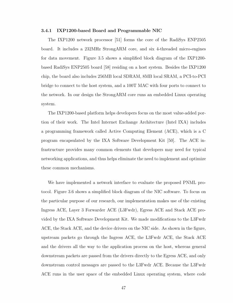
3.4.1 IXP1200-based Board and Programmable NIC
The IXP1200 network processor [51] forms the core of the RadiSys ENP2505
board. It includes a 232MHz StrongARM core, and six 4-threaded micro-engines
for data movement. Figure 3.5 shows a simplified block diagram of the IXP1200-
based RadiSys ENP2505 board [58] residing on a host system. Besides the IXP1200
chip, the board also includes 256MB local SDRAM, 8MB local SRAM, a PCI-to-PCI
bridge to connect to the host system, and a 100T MAC with four ports to connect to
the network. In our design the StrongARM core runs an embedded Linux operating
system.
The IXP1200-based platform helps developers focus on the most value-added por-
tion of their work. The Intel Internet Exchange Architecture (Intel IXA) includes
a programming framework called Active Computing Element (ACE), which is a C
program encapsulated by the IXA Software Development Kit [50]. The ACE in-
frastructure provides many common elements that developers may need for typical
networking applications, and thus helps eliminate the need to implement and optimize
these common mechanisms.
We have implemented a network interface to evaluate the proposed PNML pro-
tocol. Figure 3.6 shows a simplified block diagram of the NIC software. To focus on
the particular purpose of our research, our implementation makes use of the existing
Ingress ACE, Layer 3 Forwarder ACE (L3Fwdr), Egress ACE and Stack ACE pro-
vided by the IXA Software Development Kit. We made modifications to the L3Fwdr
ACE, the Stack ACE, and the device drivers on the NIC side. As shown in the figure,
upstream packets go through the Ingress ACE, the L3Fwdr ACE, the Stack ACE
and the drivers all the way to the application process on the host, whereas general
downstream packets are passed from the drivers directly to the Egress ACE, and only
downstream control messages are passed to the L3Fwdr ACE. Because the L3Fwdr
ACE runs in the user space of the embedded Linux operating system, where code
47

Ingress ACE
Stack ACE
Egress ACEL3Fwdr ACE
Drivers
Drivers
daemon
TCP/IP Stack
App Process
Host
NIC
Figure 3.6. Simplified block diagram of the NIC software.
development is easier due to extended library and debugging support, we have added
new functionality to the L3Fwdr and made use of it as the NMLP. The L3Fwdr ACE
receives upstream raw packets forwarded from the Ingress ACE, processes them, and
then passes them to the Stack ACE in the kernel space. It also receives some down-
stream packets containing control messages forwarded from the Stack ACE. Because
all communication traffic goes though the embedded Linux, and the L3Fwdr ACE
executes in the user space, our implementation introduces a considerable communi-
cation overhead, but it still allows the verification and preliminary evaluation of the
proposed PNML protocol.
3.4.2 The MPICH-V framework and the Berkeley Lab Checkpoint/Restart
We have implemented the proposed PNML protocol within the MPICH-V frame-
work [11, 12, 28], because it allows implementing new transparent rollback recovery
48

Protocol Layer
Abstract Device Interface
Ch_P4 Generic DeviceP
4 d a
e m o n
Generic Communication Layer
Vcl PNML TPML
Vdaemon
R u n
t i m e
A p p
l i c a t
i o n
C h a
n n e l
I n t e
r f a c e
Figure 3.7. General architecture of MPICH and the MPICH-V framework.
protocols without significant programming efforts. The MPICH-V framework is based
on the MPICH library, a widely used implementation of the MPI standard [53].
The use of MPI middleware based on the MPI standard as message-passing en-
vironment is becoming popular. The MPI standard, which defines the APIs for a
message-passing programming model, is designed to achieve portable communication
for high performance parallel applications. A number of implementations of the MPI
standard have been realized, and they are ubiquitously used in academia and industry.
Among the existing implementations, MPICH [17] is unique in its design goal of
combining portability with high performance. Its targets were to include all systems
capable of supporting the message-passing model, while giving up as little efficiency
as possible for the portability. The MPICH is freely available, and constitutes a
complete implementation of the MPI standard specification. The suffix “CH” in
MPICH stands for “Chameleon,” the symbol of adaptability to one’s environment,
and thus of portability. MPICH includes multiple implementations of the Channel
49

Interface. A channel implements the basic communication routines for a specific
hardware or for a new protocol.
The MPICH-V framework consists of a set of runtime components and a channel,
Ch V. Figure 3.7 shows the layered architecture of the MPICH-V framework. The
Ch V channel is implemented as a generic device layer on top of a specific communi-
cation daemon (Vdaemon). The generic device, independent of any rollback recovery
protocol, implements a set of six primitives used by the Protocol Layer. The commu-
nication daemon connects its peers on all the other computing nodes and the local
MPI application process, and provides all communication routines between different
components involved in the MPICH-V framework. Rollback recovery protocols are
implemented as hooks in relevant communication routines. A set of hooks is called
a V-protocol. For example, VCL is one of the V-protocols, which implements the
Chandy-Lamport Algorithm [13]. The communication daemons in a system incorpo-
rating the VCL protocol periodically perform coordinated checkpoint of distributed
applications. Users can develop new rollback recovery protocols in the Ch V channel.
In the MPICH-V framework, the checkpoint of an MPI application can be per-
formed using the Condor Standalone Checkpoint Library (CSCL) [26] or the Berkeley
Lab Checkpoint/Restart (BLCR) [22]. The CSCL is a user-level solution, whereas
BLCR is a system-level approach. A user-level implementation by its very nature
cannot fully support the restoration of any resources, for example, the process id of
a job. This rules out a wide range of applications. In contrast, a kernel-level solution
reduces potential inconsistency, and is able to support more applications.
In our implementation, the checkpointing of MPI application processes uses BLCR.
It is an open source checkpointer, implemented as a loadable kernel module for Linux
2.4.x and 2.6.x kernels on the x86 and x86-64 architectures, and a small library. In
the MPICH-V framework, when an MPI application process receives a checkpoint re-
quest from the associated local communication daemon, the application process forks
50

EthernetHeader
EthernetTrailer
IP Header
TCP Header
ChannelHeader
ADIHeader
Figure 3.8. Packet encapsulations in the MPICH-V framework
a child process. The child process sends its process image generated by BLCR to
the communication daemon, while the forking process continues its execution. In the
meantime, the communication daemon concurrently communicates with its peers on
other nodes, and receives the checkpoint image of the application process. Thus, the
checkpointing overlaps with the computation of an MPI application.
We have implemented the proposed PNML protocol within the MPICH-V frame-
work as a set of hooks in relevant communication routines of the communication
daemons, and made use of the daemons as HMPPs. In addition to communicating
with its peers and the local application process, a communication daemon exchanges
control messages with the local modified L3Fwdr ACE on the programmable NIC,
which is modeled as NMLP in our fault tolerant architecture, to accomplish the co-
ordination between checkpointing and message logging.
51

3.4.3 Implementation Issues of NMLP
In the proposed PNML protocol, an NMLP offloads message logging from a host
system to a programmable NIC on behalf of an MPI application process running on
the host system. It performs two tasks, one is to save the determinant and the content
of every received message, and the other is to coordinate checkpointing and message
logging with an HMPP running on the host side.
To accomplish the two tasks, an NMLP should save the determinants and the
received messages in a format that can be readily recognized by an HMPP to as-
sist message replaying during failure recovery, and should trace the IDs of received
messages to assist the identification of in-transmit messages during checkpointing.
Therefore, an NMLP cannot simply save received raw packets, but need to process
the received messages and get access to the information in the header of Ch V channel
messages.
An NMLP should first unpack all received packets, and assemble packet payloads
into messages. Figure 3.8 shows the packet encapsulations in the MPICH-V frame-
work. On the IXP1200-based ENP2505 boards, the buffer passed to an L3Fwdr ACE
contains a entire Ethernet frame. As we can see in the figure, the payload size is
limited by the Maximum Transmission Unit (MTU) of Ethernet, which is typically
1,500 bytes. But an MPI message may be a few hundred kilobytes, or even megabytes.
Large MPI messages are usually fragmented by the TCP layer at the sender side. To
access information in the header of a Ch V channel message, an NMLP must assemble
packet payloads into messages. Only after the assembling, can an NMLP save the
determinants and the received Ch V channel messages, and trace the ID of the last
message of every communication channel, in this case every TCP connection.
An NMLP should also be able to handle communication errors, such as packet
duplication, loss, reordering and corruption. The TCP/IP stack in OS kernels usually
handles these errors. But because an L3Fwdr ACE on an ENP2505 board receives
52

raw Ethernet frames, our implementation of the NMLP based on the L3Fwdr ACE
must correctly handle all communication errors.
Besides error handling and packet assembling, an NMLP should address another
issue associated with the coordination between checkpointing and message logging,
that is, to correctly handle partially received messages during the coordination phase.
As mentioned above, the size of a Ch V channel message may be much larger than
MTU. On the receipt of a checkpointing coordination message from the local HMPP,
an NMLP may only receives a small portion of a message. One solution is to wait
until the NMLP receives the entire message. But this may introduce an arbitrary long
delay to the saving of the in-transmit messages on the host side, especially when the
partially received message is very long. Thus, in our implementation, upon the receipt
of a checkpointing coordination message, an NMLP packs into a control message all
the IDs of the last completely received message of all connections and sends it back
to the local HMPP. If the received portion of a partially received message has already
been flushed to a message log file, then the NMLP retrieves the saved portion from the
message log file, and saves it to the new message log file opened after the checkpointing
coordination.
In our implementation, before launching a MPI application process, a commu-
nication daemon creates TCP connections with its peers, and registers the remote
IP address and the local TCP port number of every connection with the L3Fwdr-
ACE-based NMLP on the local programmable NIC. After the registration, for each
received packet, the NMLP checks its destination IP address, source IP address and
destination TCP port number against the local IP address and the pairs of registered
remote IP address and local TCP port number. Then if it is a matching packet,
the NMLP saves all information of the packet necessary for a future recovery. Our
implementation allocates two message logging buffers for each connection. When one
is flushing its content to the local hard disk, the other is used to save new arriving
53

packet payloads, and thus the periodical flushing never blocks message logging. The
NMLP copies the TCP payload of a packet to one of the two message logging buffers,
forwards the original packet buffer to the Stack ACE, and then starts to handle pos-
sible communication errors, assemble received packets into messages, and save all
information necessary for a recovery.
One problem in implementing message logging is the size of the two message log-
ging buffers. How the size of these buffers affects system performance is an unknown
factor. In our experiments, we changed the buffer size from a few hundred kilobytes to
one megabytes, but there was no notable performance impact. This might be because
the impact is negligible when compared with the performance impacts of some more
important factors in our implementation. Another problem is the scalability of our
implementation of the proposed PNML protocol. Because, in this implementation,
an NMLP allocates two large message logging buffers for every connection, it cannot
be scalable to large distributed applications.
Our implementation of the proposed PNML protocol introduces three sources of
overhead. First, each message must in general be copied to the local memory of a
programmable NIC. Second, the volatile log in the local memory is regularly flushed
to a local hard disk to free space. Third, the handling of communication errors is
duplicated on programmable NICs. The first source of overhead occurs in the criti-
cal path of the inter-process communication, and may affect directly communication
throughput and latency, even though it is better than traditional pessimistic message
logging protocols. The second source of overhead may double the required commu-
nication bandwidth between a host system and its programmable NIC when running
applications that require high bandwidth.
54

3.5 Performance Evaluation
Our experimental setup consisted of five Pentium III workstations each with a
processor running at 730MHz, 512 MB of main memory, 1GB of swap on 7200RPM
IDE hard disk,and a 33MHz PCI bus. All the workstations run Linux 2.4.17 (Redhat
Linux 7.2). We used one the five workstations as a monitor node, and the other four
as computing nodes. In our experiments, we started the execution of an MPI program
by initiating a management process called Dispatcher [12] on the monitor node. The
Dispatcher’s task is primarily to launch communication daemons on all participating
computing nodes, each communication daemon instantiating an MPI process on its
node. We installed an IXP1200-based RadiSys ENP2505 board on each of the four
computing nodes, and loaded the L3Fwdr-ACE-based NMLP on each of the four
boards. All the workstations are connected via ethernet cables and a switch.
In the experiments, we used MPICH-V version 1.2.7p1. Most test programs were
compiled using GNU GCC, version 2.96, G77, version 2.96. But because one test pro-
gram, NPB FT, could not be compiled with G77, we compiled it using a commercial
Fortran 77 compiler, PGI PGF77, version 5.2-4.
Our performance evaluation considers coordinated checkpoint based on the Chandy-
Lamport algorithm (VCL [12]), PNML and Traditional Pessimistic Message Logging
(TPML). We implemented both PNML and TPML in the MPICH-V framework. All
tests were run in dedicated mode.
For a fair comparison between different protocols, we disabled checkpointing in
all of our experiments. This is because all the three protocols use similar checkpoint
mechanism, the checkpointing overhead is primarily determined by the checkpoint
interval and the execution time of an MPI application. To justify the experimental
setup, we also did experiments to evaluate the overhead introduced by the coordi-
nation between checkpointing and message logging in the proposed PNML protocol.
We emulated a 4-process system and a 64-process system on a workstation with an
55

ENP2505 board, and the average blocking time incurred by the coordination increased
from 737.0 to 827.8 μs, nearly no impact on the overall performance in practice.
3.5.1 Raw Communication Performance
In the first set of experiments, we used the NetPIPE [39] utility to measure the
raw communication performance of the three protocols. We performed a ping-pong
test to evaluate the effective latency and bandwidth of message transmissions between
processes on two nodes.
Figures 3.9 and 3.10 present the comparison of the point-to-point half-round-trip
latency obtained with the three protocols for different message lengths. Figures 3.11
and 3.12 compare bandwidth. As we can see from these figures, the performance of
the programmable NICs used in our experiments is very slow, due to the reason we
have discussed in Section 3.4.1. The figures show that when the message length is less
than or equal to 256 KB, PNML remains close to VCL, and is notably better than
TPML. But for messages larger than 256 KB, the performance of PNML significantly
drops, even worse than TPML. This slowdown is because the message logging opera-
tions of PNML compete for bandwidth with regular communication traffic. The slow
programmable NICs in some sense magnify the performance impact of PNML, as
faster NICs with much higher bandwidth may start to slow down when the message
length is much larger than 1 MB. However, because typically the average message
size of an MPI application is only a few tens KB, and very large messages are rare,
our implementation is still adequate to preliminarily evaluate the proposed PNML
protocol.
3.5.2 The NAS Parallel Benchmark
In the second set of experiments, we tested the performance of the three proto-
cols on well established and optimized MPI programs, the NAS Parallel Benchmarks
(NPB) [9], version 2.3. NPB is widely used to evaluate the performance of parallel
56

5
10
15
20
1 4 16 64 256 1K 4K 16K 64K 256K
Late
ncy
(104
µs)
Message Length (byte)
Coordinated CheckpointProgrammable-NIC-assisted ML
Traditional Pessimistic ML
Figure 3.9. Latency of rollback recovery protocols
5
10
15
20
25
1 4 16 64 256 1K 4K 16K 64K 256K
Late
ncy
(103
µs)
Message Length (byte)
Programmable-NIC-assisted MLTraditional Pessimistic ML
Figure 3.10. Latency difference between message logging protocols and the coordi-nated checkpointing (VCL)
57

0
2
4
6
8
10
12
14
1 4 16 64 256 1K 4K 16K 64K 256K 1M
Ban
dwid
th (M
B/s
)
Message Length (byte)
Coordinated CheckpointProgrammable-NIC-assisted ML
Traditional Pessimistic ML
Figure 3.11. Bandwidth of rollback recovery protocols
0
1
2
3
4
5
1 4 16 64 256 1K 4K 16K 64K 256K 1M
Ban
dwid
th D
iffer
ence
(MB
/s)
Message Length (byte)
Programmable-NIC-assisted MLTraditional Pessimistic ML
Figure 3.12. Bandwidth difference between message logging protocols and the co-ordinated checkpointing (VCL)
58

0
200
400
600
800
CG EP LU MG BT IS SP FT
Coordinated CheckpointProgrammable-NIC-assisted ML
Traditional Pessimistic ML
Figure 3.13. Performance comparison of protocols for NPB Class W
0
500
1000
1500
2000
2500
CG EP LU MG BT IS SP FT
Coordinated CheckpointProgrammable-NIC-assisted ML
Traditional Pessimistic ML
Figure 3.14. Performance comparison of protocols for NPB Class A
59

systems, because it mirrors real-world parallel scientific applications better than most
other parallel benchmarks.
For each benchmark program, NPB specifies five classes of increasing workloads,
called S, W, A, B, and C. Class S is suitable for testing, Class W for single-processor
desktop workstations, Class A for systems with up to 32 processors, while Classes B
and C are suited for multiprocessor systems.
Figures 3.13 and 3.14 present the performance comparison of the three protocols
for the NPB 2.3, for Class W and Class A size problems, respectively. The NAS
EP program measures the upper limits achievable for floating point performance,
without significant interprocessor communication, so that the execution time of the
three protocols for EP is almost the same. For all the other benchmark programs, the
performance of PNML is worse than VCL, but better than TPML. For Class W size
problem, the overhead introduced by PNML is between 3.6% and 14.9% compared
to VCL, and for Class A size problem, the overhead is between 3.4% and 16.3%.
As we can see, the performance of TPML is close to that of VCL. This is again
because of the slow programmable NICs used in the experiments. Since we disabled
checkpointing, the overhead imposed by VCL is negligible. However, in a system with
relatively faster interconnection, the failure free overhead imposed by TPML is over
70% [36]. The long communication delay hides the message logging overhead.
The largest performance difference came forth when we tested the execution time
of the three protocols on the NPB LU benchmark. The LU benchmark includes a large
number of small communications. Because of the largest message logging overhead
among all the three protocols, TPML causes a significant performance degradation
compared to the other two. A related research has shown that the communication
daemon of a sender-based pessimistic message logging protocol, also in charge of
message logging, competes for CPU resources with the MPI process in this case [10].
60

The performance advantage of PNML over TPML is not quite evident for the BT
and SP benchmarks. Over and above the slow NICs, this is because the long-duration
BT and SP benchmarks exchange many large messages, and stress communication
bandwidth. If we compare Figure 3.13 with Figure 3.14, we can find that the perfor-
mance advantage of PNML over TPML turns to be relatively small. Similarly, this
is because the message sizes scale up when the problem sizes of these benchmarks
increase from Class W to Class A.
61

CHAPTER 4
SUMMARY AND FUTURE WORK
In this dissertation, we proposed a layered fault tolerance architecture that is
composed of two fault tolerant elements on each of the computing nodes in a dis-
tributed/parallel system, one resides on the host system and the other on the I/O
attached programmable NIC. Each fault tolerant element keeps track of the health
of the other and start recovery upon a failure. The proposed fault tolerance archi-
tecture takes advantage of the collaboration between the host processor and the NIC
processor to develop fault tolerant techniques that will allow the system to quickly re-
cover from failures without a significant penalty in performance. In this dissertation,
we investigate how to improve system reliability with minimal performance overhead
through the proposed fault tolerance architecture.
In the first half of our work, we proposed and developed a software-based low-
overhead failure detection scheme for programmable network interfaces. The failure
detection is achieved by a watchdog timer that detects network interface hangs, and a
built-in ACST scheme that detects non-interface-hang failures. The proposed ACST
scheme directs the control flow to go through all the basic blocks in active logical
modules. During this procedure, the functionalities of the network interface, essen-
tially the hardware and the active logical modules of the software, are tested. Our
experimental results are very promising. In the local memory of the Myrinet inter-
face card, over 95% of the bit-flip errors that may affect applications can be detected
by our self-testing scheme in conjunction with a software watchdog timer. The pro-
posed ACST scheme can be implemented transparently to applications. To the best
62

of our knowledge, this is the first effort that applies self-testing to a programmable
network interface to detect bit flips in memory cells. The basic idea underlying the
presented failure detection scheme is quite generic and can be applied to other mod-
ern high-speed programmable networking devices, that contain a microprocessor and
local memory, such as IBM PowerNP [5], Infiniband [52], Gigabit Ethernet [42, 49],
QsNet [56] and ATM [48]. Such a failure detection scheme can take advantage of
the high bandwidth available in these systems, thereby achieving its failure detection
goals with very little overhead.
In the second half of our work, we proposed the PNML protocol. We assume that
the local memory of a programmable NIC is a safe place to save recovery information.
During failure-free execution, instead of synchronously saving recovery information to
slow stable storage in the critical path of inter-process communication, like traditional
receiver-based pessimistic message logging protocols, an NMLP on a programmable
NIC saves the determinants and the content of messages in the local memory on be-
half of an MPI application process running on the host, offloading message logging
operations from host to programmable NIC. Thus, the PNML protocol can notably
reduce failure-free execution overhead. During checkpointing phase, the NMLP coop-
erates with its HMPP on the host side to coordinate the checkpointing and message
logging. The coordination is simple and quite efficient, introducing a blocking delay
on the order of the magnitude of one millisecond. The proposed PNML combines the
efficiency and simplicity aspects of existing message logging protocols, and thus pro-
vides attractive features like low failure-free performance overhead, fast recovery and
fast interaction with I/O devices. Furthermore, in the PNML protocol, no operations
require global coordination, a highly desirable feature in practice, especially for large
scale systems. We have implemented the proposed PNML protocol on IXP1200-based
RadiSys ENP2505 boards. The PNML protocol outperforms the baseline receiver-
63

based pessimistic message logging protocol, especially in cases where processes of an
MPI application exchange a high number of small messages.
In the dissertation, we assume that only application processes may fail. We can
relax this assumption, and assume that a communication daemon or a host oper-
ating system may also fail. In case that a operating system fails, we can have the
programmable NIC raise an interrupt after the detection of the failure, and in the
kernel space of the failed host operating system, have the interrupt handler call the
restart routine to reboot the failed operating system. If the interrupt logic is cor-
rupted, we can have a resetting signal sent from a pin on the programmable NIC
to the reset button of the NIC’s residing workstation and reboot it. The recovery
of a failed communication daemon is simpler, because a daemon is stateless in our
implementation. A Dispatcher can simply relaunch a failed communication daemon
and retrieve all recovery information from either a hard disk or the volatile memory
of a programmable NIC.
To further relax the failure assumption, tolerate more types of failures, and attack
the major sources of overhead of the proposed PNML protocol, we need to develop an
improved PNML. In the new model, we can assume that either a host system or a pro-
grammable NIC may partially or completely fail, but they never fail simultaneously.
This is a reasonable assumption, because a host system and a NIC system usually run
in their own memory space, physically separate. Furthermore, we can consolidate the
assumption by introducing fault isolation techniques to prevent faults to propagate
from the host side to the NIC side, or vice versa. We can then offload the TCP/IP
stack from a host system to a programmable NIC. On one hand, the offloading im-
proves the degree of I/O and CPU parallelism and thus the performance; on the other
hand, it eliminates one of the two duplicated communication error handling opera-
tions as in a system incorporating PNML, and completely removes the third source
of overhead introduced by PNML. To tolerate more types of failures and attack the
64

second source of overhead, we can have both the host system and the NIC save a
copy of a received message and the corresponding determinant. If either of the two
fails, we can still find all necessary recovery information from the surviving one, and
thus be able to tolerate NIC failures in addition to host failures. During failure-free
execution, the host side HMPP asynchronously saves recovery information to stable
storage off the critical path, and after each saving, informs the NMLP to release
the corresponding buffer. This solution may require frequent exchange of very short
control messages between an HMPP and its NMLP, but eliminates the second source
of overhead because of the periodical flushing of large communication messages, and
thus is highly promising. Finally, we can have the improved PNML protocol share
the message log with the transmission buffers, and thus eliminate the first source of
overhead, the copying in the critical path of the inter-process communication. The
resulting improved PNML may approach the performance of coordinated checkpoint-
ing, retain all the advantages of receiver-based pessimistic message logging protocols,
and become a highly desirable log-based rollback-recovery protocol in practice.
65

BIBLIOGRAPHY
[1] D. Andrews, “Using Executable Assertions for Testing and Fault Tolerance,”
Proceedings of the Ninth International Symposium on Fault-Tolerant Computing,
pp. 102-105, Jun. 1979.
[2] L. Alvisi, K. Marzullo, “Message logging : Pessimistic, optimistic, and causal,”
Proceedings of the Fifteenth International Conference on Distributed Computing
Systems (ICDCS 1995), pp. 229-236, May-Jun. 1995.
[3] L. Alvisi, K. Marzullo, “Tradeoffs in implementing causal message logging pro-
tocols,” Proceedings of the ACM SIGACT-SIGOPS Symposium on Principles of
Distributed Computing (PODC), pp. 58-67, 1996.
[4] L. Alvisi, K. Marzullo, “Message Logging: Pessimistic, Optimistic, Causal and
Optimal,” IEEE Transactions on Software Engineering, vol. 24, No. 2, pp. 149-
159, 1998.
[5] J. R. Allen, Jr., B. M. Bass, C. Basso, R. H. Boivie, et al., “IBM PowerNP
Network Processor: Hardware, Software, and Applications,” IBM Journal of
Research and Development, vol. 47, No. 2/3, pp. 177-194, Mar./May 2003.
[6] A. Borg, W. Blau, W. Graetsch, F. Hermann, W. Oberle, “Fault tolerance under
UNIX,” ACM Transactions on Computer Systems, vol. 7, No. 1, pp. 1-24, 1989.
[7] R. M. Butler, E. L. Lusk, “Monitors, Messages, and Clusters: The p4 Parallel
Programming System,” Parallel Computing, vol. 20, No. 4, pp. 547-564, Apr.
1994.
66

[8] N. J. Boden, D. Cohen, R. E. Felderman, A. E. Kulawik, C. L. Seitz, J. N.
Seizovic, W.-K. Su, “Myrinet – A Gigabit-per-Second Local-Area Network,”
IEEE Micro, vol. 15, No. 1, pp. 29-36, Feb. 1995.
[9] D. Bailey, T. Harris, W. Saphir, R. Wijngaart, A. Woo, M. Yarrow, “The NAS
Parallel Benchmarks 2.0,” Numerical Aerodynamic Simulation Facility, NASA
Ames Research Center, Report NAS-95-020, 1995.
[10] A. Bouteiller, F. Cappello, T. Herault, G. Krawezik, P. Lemarinier, F. Magniette,
“MPICH-V2: a Fault Tolerant MPI for Volatile Nodes based on the Pessimistic
Sender Based Message Logging,” Proceedings of The IEEE/ACM Supercomput-
ing Conference (SC2003), Nov. 2003.
[11] A. Bouteiller, P. Lemarinier, G. Krawezik, F. Cappello, “Coordinated checkpoint
versus message log for fault tolerant MPI,” IEEE International Conference on
Cluster Computing, Dec. 2003.
[12] A. Bouteiller, T. Herault, G. Krawezik, P. Lemarinier, F. Cappello, “MPICH-V
Project: A Multiprotocol Automatic Fault-Tolerant MPI,” International Journal
of High Performance Computing and Applications, SAGE publications, vol. 20,
No. 3, pp. 319-333, 2006.
[13] K. Chandy, L. Lamport, “Distributed Snapshots: Determining Global States of
a Distributed System,” ACM Transactions on Computer Systems vol. 3, No. 1,
pp. 63-75, Feb. 1985.
[14] R. Chillarege, “Self-testing Software Probe System for Failure Detection and
Diagnosis,” Proceedings of the 1994 conference of the Centre for Advanced Studies
on Collaborative Research, pp. 10, 1994.
67

[15] E. N. Elnozahy, W. Zwaenepoel, “Manetho: Transparent Roll Back-Recovery
with Low Overhead, Limited Rollback, and Fast Output Commit,” IEEE Trans-
actions on Computers, vol. 41, No. 5, pp. 526-531, May 1992.
[16] E. N. Elnozahy, L. Alvisi, Y.-M. Wang, D. B. Johnson, “A Survey of Rollback-
Recovery Protocols in Message-Passing Systems,” ACM Computing Surveys
(CSUR), vol. 34, No. 3, pp. 375-408, Sep. 2002.
[17] W. Gropp, E. Lusk, N. Doss, A. Skjellum, ”A High-Performance, Portable Imple-
mentation of the MPI Message Passing Interface Standard,” Parallel Computing,
North-Holland, vol. 22, pp. 789-828, 1996.
[18] K. H. Huang, J. A. Abraham, “Algorithm-Based Fault Tolerance for Matrix
Operations,” IEEE Transactions on Computers, vol. 33, pp. 518-528, Dec. 1984.
[19] Y. Huang, C. M. R. Kintala, “Software implemented fault tolerance: Tech-
nologies and experience,” Proceedings of the Twenty-Third Annual International
Symposium on Fault-Tolerant Computing (FTCS-23), pp. 2-9, 1993.
[20] T. Halfhill. “Intel Network Processor Targets Routers,” Microprocessor Report,
vol. 13, No. 12, pp. 66-68, Sep. 1999.
[21] S. Hareland, J. Maiz, M. Alavi, K. Mistry, S. Walstra, C. Dai, “Impact of CMOS
Scaling and SOI on Soft Error Rates of Logic Processes,” Proceedings of Sympo-
sium on VLSI Technology, pp. 73-74, 2001.
[22] P. H. Hargrove, J. C. Duell, “Berkeley Lab Checkpoint/Restart (BLCR) for
Linux Clusters,” Proceedings of Scientific Discovery through Advanced Comput-
ing Program (SciDAC) Conference, Jun. 2006.
68

[23] D. B. Johnson, W. Zwaenepoel, “Sender-based message logging,” Proceedings of
the Seventeenth Annual International Symposium on Fault-Tolerant Computing
(FTCS-17), pp. 14-19, 1987.
[24] T. Karnik, B. Bloechel, K. Soumyanath, V. De, S. Borkar, “Scaling Trends of
Cosmic Rays Induced Soft Errors in Static Latches Beyond 0.18μ,” Proceedings
of Symposium on VLSI Circuits, pp. 61-62, 2001.
[25] A. V. Karapetian, R. R. Some, J. J. Beahan, “Radiation Fault Modeling and
Fault Rate Estimation for a COTS Based Space-borne Supercomputer,” Pro-
ceedings of IEEE Aerospace Conference, vol. 5, pp. 9-16, Mar. 2002.
[26] M. Litzkow, T. Tannenbaum, J. Basney, M. Livny, “Checkpoint and migration
of unix processes in the condor distributed processing system,” Technical Report
CS-TR-199701346, University of Wisconsin-Madison, Apr. 1997.
[27] V. Lakamraju, I. Koren, C. M. Krishna, “Low Overhead Fault Tolerant Network-
ing in Myrinet,” Proceedings of the Dependable Computing and Communications
Symposium, pp. 193-202, Jun. 2003.
[28] P. Lemarinier, A. Bouteiller, T. Herault, G. Krawezik, F. Cappello, “Improved
Message Logging versus Improved Coordinated Checkpointing for Fault Tolerant
MPI,” Proceedings IEEE International Conference on Cluster Computing, Sep.
2004.
[29] M. Morisio, N. L. Sunderhaft, “Commercial-Off-The-Shelf (COTS): A Survey,”
Data and Analysis Center for Software, Technical Report, Dec. 2000.
[30] S. S. Mukherjee, J. Emer, S. K. Reinhardt, “The Soft Error Problem: An Archi-
tectural Perspective,” Proceedings of the Eleventh International Symposium on
High-Performance Computer Architecture, pp. 243-247, Feb. 2005.
69

[31] B. Nicolescu, R. Velazco, “Detecting Soft Errors by a Purely Software Approach:
Method, Tools and Experimental Results,” Proceedings of Design, Automation
and Test in Europe Conference and Exhibition (DATE’03 Designers’ Forum),
vol. 2, pp. 57-62, Mar. 2003.
[32] N. Oh, P.P. Shirvani, E.J. McCluskey, “Error Detection by Duplicated Instruc-
tions in Super-scalar Processors,” IEEE Transactions on Reliability, vol. 51, No.
1, pp. 63-75, Mar. 2002.
[33] D. K. Pradhan, Fault-Tolerant Computer System Design, Prentice Hall PTR,
1996.
[34] L. L. Pullum, Software Fault Tolerance Techniques and Implementation, Artech
House, 2001.
[35] S. Rao, L. Alvisi, H. M. Vin, “Hybrid Message-Logging Protocols for Fast Re-
covery,” Digest of Fast Abstracts of The Twenty-Eighth International Symposium
on Fault-Tolerant Computing, pp. 41-42, Jun. 1998.
[36] S. Rao, L. Alvisi, H. M. Vin, “The Cost of Recovery in Message Logging Proto-
cols,” IEEE Transactions on Knowledge and Data Engineering, vol. 12, No. 2,
pp. 160-173, Mar./Apr. 2000.
[37] R. D. Schlichting, F. B. Schneider, “Fail-stop Processors: An Approach to De-
signing Fault-Tolerant Computing Systems,” ACM Transactions on Computer
Systems, vol. 1, No. 3, pp. 222-238, 1983.
[38] R. Strom, S. Yemini, “Optimistic Recovery in Distributed Systems,” ACM Trans-
actions on Computer Systems, vol. 3, No. 3, pp. 204-226, 1985.
70

[39] Q. O. Snell, A. R. Mikler, J. L. Gustafson, “NetPIPE: A Network Protocol
Independent Performance Evaluator,” Proceedings of The IASTED International
Conference on Intelligent Information Management and Systems, Jun. 1996.
[40] D. T. Stott, M.-C. Hsueh, G. L. Ries, R. K. Iyer, “Dependability Analysis of
a Commercial Highspeed Network,” Proceedings of the Twenty-Seventh Annual
International Symposium on Fault-Tolerant Computing, pp. 248-257, Jun. 1997.
[41] P. P. Shirvani, N. R. Saxena, E. J. McCluskey, “Software-Implemented EDAC
Protection Against SEUs,” IEEE Transactions on Reliability, vol. 49, No. 3, pp.
273-284, Sep. 2000.
[42] P. Shivam, P. Wyckoff, D. Panda, “EMP: Zero-copy OS-bypass NIC-driven Giga-
bit Ethernet Message Passing,” Proceedings of The IEEE/ACM Supercomputing
Conference (SC2001), pp. 57-57, Nov. 2001.
[43] A. Thakur, R. K. Iyer, “Analyze-NOW-an environment for collection of analysis
of failures in a network of workstation,” Proceedings of the Seventh International
Symposium on Software Reliability Engineering, pp. 14-23, Oct. 1996.
[44] S. S. Yau, F.-C. Chen, “An Approach to Concurrent Control Flow Checking,”
IEEE Transactions on Software Engineering, vol. 6, No. 2, pp. 126-137, Mar.
1980.
[45] J. F. Ziegler, et al., “IBM Experiments in Soft Fails in Computer Electronics
(1978-1994),” IBM Journal of Research and Development, vol. 40, No. 1, pp.
3-18, Jan. 1996.
[46] Y. Zhou, V. Lakamraju, I. Koren, C. M. Krishna, “Software-Based Adaptive
and Concurrent Self-Testing in Programmable Network Interfaces,” Proceedings
of the Twelfth International Conference on Parallel and Distributed Systems (IC-
PADS’06), vol. 1, pp. 525-532, 2006.
71

[47] Y. Zhou, V. Lakamraju, I. Koren, C. M. Krishna, “Software-Based Failure De-
tection and Recovery in Programmable Network Interfaces,” IEEE Transactions
on Parallel and Distributed Systems, vol. 18, No. 11, pp. 1539-1550, Nov. 2007.
[48] A.T.M. Forum. ATM User-Network Interface Specification, Prentice Hall, 1998.
[49] The Gigabit Ethernet Alliance, http://www.gigabit-ethernet.com/.
[50] Intel Corporation, “Intel IXA SDK ACE Programming Framework - IXA SDK
2.01 Developer’s Guide,”
http://www.intel.com/design/network/products/npfamily/index.htm, Dec. 2001.
[51] Intel Corporation, “Intel IXP1200 Network Processor Family - Harware Refer-
ence Manual, ”
http://www.intel.com/design/network/products/npfamily/index.htm, Dec. 2001.
[52] Infiniband Trade Association, http://www.infinibandta.com/.
[53] Message Passing Interface Forum, http://www.mpi-forum.org/.
[54] Myricom Inc, http://www.myri.com/.
[55] “Single Event Effects Specification,”
http://radhome.gsfc.nasa.gov/radhome/papers/seespec.htm.
[56] The QsNet High Performance Interconnect, http://www.quadrics.com/.
[57] “Remote Exploration and Experimentation (REE) Project,” http://www-
ree.jpl.nasa.gov/.
[58] RadiSys Corporation, “ENP2505 Hardware Reference,” Nov. 2002.
[59] The Human Impacts of Solar Storms and Space Weather.
http://www.solarstorms.org/Scomputers.html.
72