Embed Size (px)
Citation preview
BUTLER EMERGENCY RESMNSE PLAN• ' (IERP) •
*DiiDDncc «• : federal On-Scene Coordinators Report '•PURPOSE . Major Pollut1on incidentPittston, PA., Butler Tunnel
> . Federal Project No. 1-9-0075*AUTHORITY "
Volume II \ "Butler Emergency Response Plan (BERP)"Appendix VI j On-Scene Coordinator
*RESPONSE ORGANIZATION :
•OPERATIONS/MONITORINGPHASE I, II, IIIOPERATIONS RESPONSE
*FACILITY LOCATION AND EQUIPMENT DESCRIPTION
UPON THE COMPLETION AND SATISFACTORY OPERATION OF THE UNMANNED POLLUTANTCONTAINMENT FACILITY THIS PLAN WILL BECOME EFFECTIVE. THIS OPERATION WILLCONTINUE UNTIL SUCH TIME AS CONDITIONS PERMIT"THE DEACTIVATION OF THISFACILITY MUTUALLY AGREED UPON BY PA DER AND US EPA.
James W. Chester Thomas I. MasseyRegional Director Federal On-Scene CoordinatorPA Department of Environmental Resources • EPA Region III PhiladelphiaHiIkes Barre, PA
November 1980
I 07
t!
BUTLER EMERGENCY RESPONSE PLAN(BERP)
C URPOSE
-AUTHORITY
•RESPONSE ORGANIZATION
*OP£RATIONS/MONITORINGPHASE I. II. IllOPERATXONS RESPONSE
•FACILITY LOCATION AND EQUIPMENT DESCRIPTION
UPON THE COMPLETION AND SATISFACTORY OPERATION OF THE UNMANNED POLLUTANTCONTAINMENT FACILITY THIS PLAN MILL BECOME EFFECTIVE. THIS OPERATION WILLCONTINUE UNTIL SUCH TIME AS CONDITIONS PERMIT THE OE ACT I VAT I ON OF THISFACILITY MUTUALLY AGREED UPON BY PA OER AND US £PA.
*Z-~~Tomas lVMa«cyy director .Federal On-SceneVyO«pa«-tm«nt of Environmental Resource* EPA Region XII pni
wi 1 k«* Bttrrci • PA

BUTLER EMERGENCY RESPONSE PLAN(BERP)
PURPOSE:
To protect the public health and the environment from •damaging effects of a pollution discharge Into theSusquehanna from the Butler Tunnel 1n Plttston, PA.
AUTHORITY:
Clean Streams Law
____ Section 311 of Public Law 92-500
RESPONSE ORGANIZATIONS;
• State; • PA Department of Environmental Resources——— 90 E. Union Street
Uilkes Barre, PA 18701(717) 826-2058James W. ChesterRegional DirectorOffice of Deep Mine SafetyPA DER6th floorFulton National Bank BuildingHarrlsburg, PA 18701
• (717) 787-1376Walter. VI ci nellyCommissioner
Federal : United States Environmental Protection AgencyRegion III6th and Walnut StreetsPhiladelphia, PA 19106(215) 597-9898Thomas I. MasseyOn-Scene Coordinator
i
United States Environmental Response Team (ERT)Woodbrldge AvenueEdison, NJ 08817(212) 321-6741Dr. Joseph Lafornara
flRi»OOI09'
•d-vs, l\
^ — -a
OPERATIONS AND MONITORING *"*
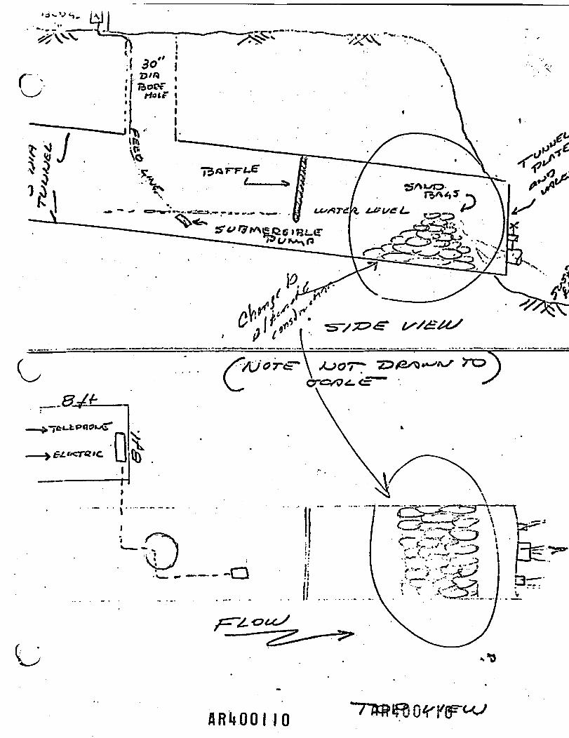
This system Is designed to provide a continuous unmanned observation of the
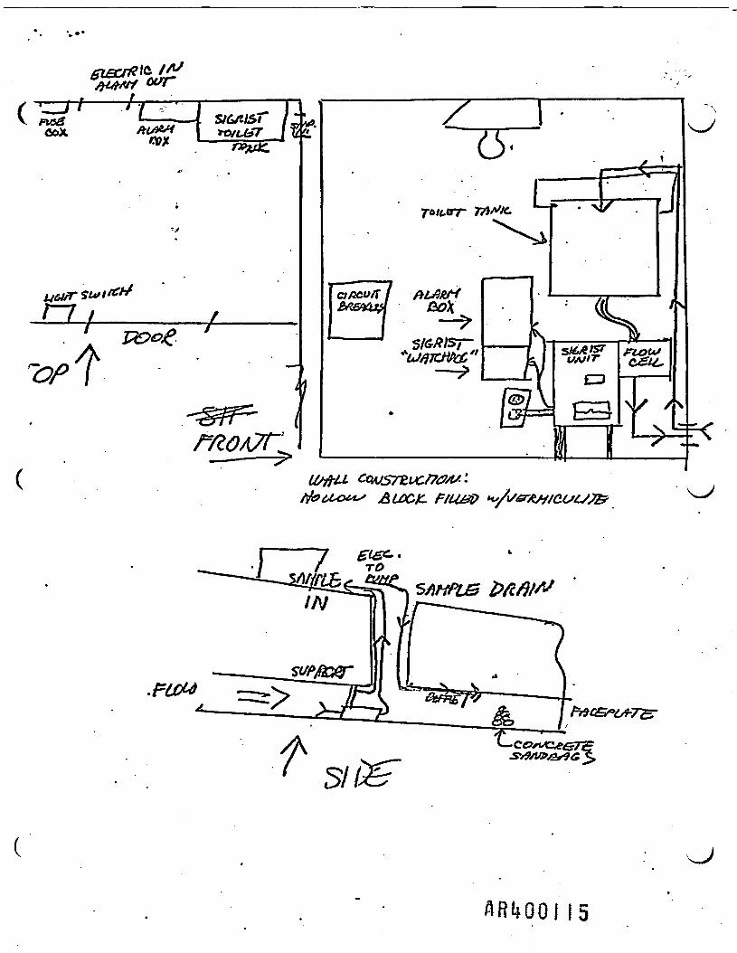
tunnel outfall discharge. The unmanned pollutant containment facility at theButler Tunnel consists of a custom designed oil/water separator inside thefive (5) foot diameter tunnel near, the discharge point into the SusquehannaRiver. The integrated system for real time analysis of the effluent to deter-mine the potential spread of pollutants will be installed in the tunnel as shownin following sketch.
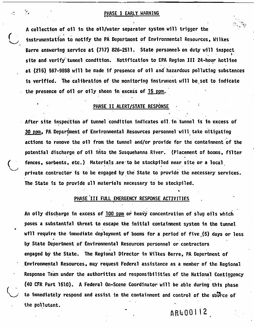
PHASE 1 EARLY WARNING
A collection of oil In the oil/water separator system will trigger the
Instrumentation to notify the PA Department of Environmental Resources, Wilkes
Barre answering service at (717) 826-2511. State personnel* on duty will inspectsite and verify tunnel condition. Notification to EPA Region III 24-hour hotline
at (215) 597-9898 will be made 1f presence of oil and hazardous polluting substances
1s verified, the calibration of the monitoring Instrument will be set to indicatethe presence of oil or oily sheen in excess of 15 ppm.
PHASE II ALERT/STATE RESPONSE :
After site Inspection of tunnel condition Indicates oil. in tunnel is in excess of30 ppm, PA Department of Environmental Resources personnel will take mitigating
actions to remove the oil from the tunnel and/or provide for the containment of the
potential discharge of oil Into the Susquehanna River. (Placement of booms, filterfences, sorbents, etc.) Materials.are-to be stockpiled near site or a local
private contractor 1s to be engaged by the State to provide the necessary services.
The State is to provide all materials necessary to be stockpiled.*
PHASE 'ill FULL EMERGENCY RESPONSE ACTIVITIES
An oily discharge in excess of 100 ppm or heavy concentration of slug oils which
poses a substantial threat to escape the initial containment system in the tunnelwill require the immediate deployment of booms for a period of five .(5) days or lessby State Department of Environmental Resources personnel or contractors
i •engaged by the State. The Regional Director in Wilkes Barre, PA Department of
' Environmental Resources, may request Federal assistance as a member of the Regional
Response Team under the authorities and responsibilities of the National Contingency
(40 CFR Part 1510). A Federal On-Scene Coordinator will be able during this phase
1 to immediately respond and assist in the containment and control of the source ofthe pollutant.
" . A R U Q Q I I 2 :
FACILITY LOCATION AND DESIGN -——————————————————.
• • ' * . . tAn 8 foot square by an 8 foot high concrete block building will be constructed
near the existing 30 Inch borehole cover over the Butler tunnel. This building
will have one metal door and shall have adequate security. Electric and telephoneservice shall be provided to this building from the existing systems presently1n place. A spill alarm system and auxiliary equipment will be placed Inside
•
this building. Supply feed lines are to be connected from the Inside of thebuilding to a submersible pump Inside Butler Tunnel. The building 1s to beadequately heated In such a manner as to protect the monitoring equipment from
freezing. • . •Costs for the construction of the building, monitoring equipment, and Installationof electrical and telephone connections will be funded under the Federal removal
project. The State of Pennsylvania will take title to the building and allequipment described herein. All subsequent maintenance cost and repairs including
telephone and electrical charges will be paid through State*resources.
RRWOH3
•' ' . =' EQUIPMENT DESCRIPTION
The monitoring equipment consists of a flow through ultraviolet fluorescence
o1l-1n-water detector. This unit 1s approved by the United States Coast Guard
for monitoring .oil concentrations In ships for bilge water discharges. Anyequipment used 1n the confines of the underground tunnel will be subject tothe statutory requirements of the PA Anthrlclte Laws as enforced by the Officeof Deep Mine Safety, PA Department of Environmental Resources. The enclosedmanufacturer equipment description details the operations and maintenance
of this unit.
ARlfQO'lU '
ARI»OOII5
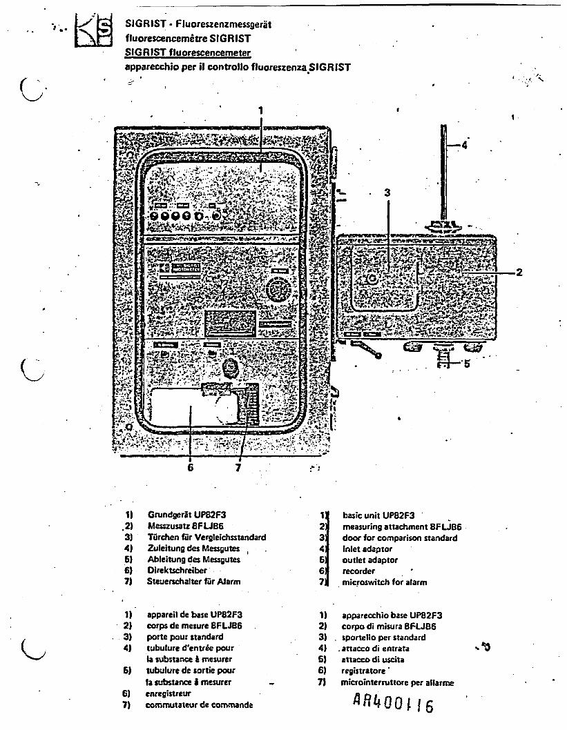
SIGRIST • Fluoreszenzmessgeratfluorescencemetre SIGRISTSIGRIST fluorescencemeterapparecchio per il controllo fluoreszenza SIGRIST
. « • • • • ^••W ^ . f l*-* f
1) Grundgcrat UP82F3 1.2} Messzusatz 8FUB6 23) Turchen fur Vergteichsstandard 34) Zuleitung des Messgutes , . 4!5} Ableitung des Messgutes 6!6) Direktschreiber 6|7) Steuerschalter fur Alarm 7,
basic unit UP82F3measuring attachment 8FLJB6door for comparison standardinlet adaptoroutlet adaptorrecordermicroswitch for alarm
1) appareil de base UP82F3 1) apparecchio base UP82F32) corps de mesure 8FLJB6 2) corpo di misura 8FLJB63) porte pour standard 3) . sportello per standard4) tubulure d'entree pour 4) . anacco di entrata - *9
la substance i mesurer 5) attacco di uscita5) tubulure de sortie pour 6) registratore'
la substance 2 mesurer - 7} microinterruttore per allarme6) enregistreur7) commutateurdecommande
(
c
2. DESIGN OF THE SIGRIST. PHOTOMETER •-
2.1 SIGRIST PHOTOMETER
The Sigrist Photometer consists of the "basic* unit"-and a "measuring attachment" (please revert to layoutdrawing). Basic unit and measuring attachment areboth built on a torsion-fira steel frame whichguarantees immovable position of all optical com-ponents. Both are enclosed in varnished steel cases*protecting instrument parts from dust, moisture, andliquids. The doors of the basic unit and themeasuring attachment must, therefore, be locked at
. all times.
2.2 CHARACTERISTICS ••
- Due to the, method of the completely opticalmeasuring bridge - with only one light source, onephotocell, and the automatic optical adjustment -the Sigrist Photometer is an instrument ofexceptionally high stability and precision. \^s
-. The measured values will not be affected by voltagefluctuations, aging of the light source, sensitivitydifferences in the photocell, or the degree ofamplification and the inherent instability of allamplifiers.
- For this reason, the supplementary stabilizationdemanded by other electronic instruments is en-tirely precluded. Furthermore, no thermostatizationis necessary.
- Consequently, this entirely optical measuringmethod provides outstanding stability of theadjustment point with a deviation of only +_ 0.5%.It remains stable for long periods.
- In principle, a rigid mirror or prism can be usedin place of the oscillating mirror for physicalsplitting into two beams, in combination with a
' f rotating shutter to separate the two light pathsin time. It is necessary, however, as with theoscillating mirror, to assure that there is syn-chronization between the motion of the rotatingshutter and the demodulation voltage. Experiencehas sh'own that this is particularly costly in thecase of rotating shutters.
A B U O O I 1 7
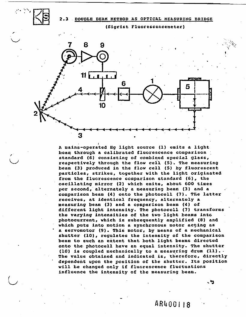
y2.3 DOUDLE DEAM METHOD AS OPTICAL MEASURING DRIDGE
(Sigrist Fluoresccnceneter)
H 51
<
I
r
«—<—4—«—«-
A mains-operated Hg light source (1) emits a lightbeam through a calibrated fluorescence comparisonstandard (6) consisting of combined special glass,respectively through the flow cell (5). The measuringbeam (3) produced in the flow cell (5) by fluorescentparticles, strikes, together with the light originatedfrom the fluorescence comparison standard (6)., theoscillating mirror (2) which emits, abfcut 600 timesper second, alternately a measuring beam (3) and acomparison beam (4) onto the photocell (7). The latterreceives, at identical frequency, alternately ameasuring beam (3) and a comparison beam (4) ofdifferent light intensity. The photocell (7) transformsthe varying intensities of the two light beams intophotocurrent, which is subsequently amplified (8) andwhich puts into motion a synchronous motor acting asa servomotor (9). This motor, by means of a mechanicalshutter (10), regulates the intensity of the comparisonbeam to such an extent that both light beams directedonto the photocell have an equal intensity. The shutter(10) is coupled mechanically to a measuring drum (11). •The value obtained and indicated is, therefore, directlydependent upon the position of the shutter. Its positionwill be changed only if fluorescence fluctuationsinfluence the intensity of the measuring beam.
ARl»OOi 18