Embed Size (px)
Citation preview

IEEE TRANSACTIONS ON POWER DELIVERY, VOL. 28, NO. 1, JANUARY 2013 129
Accelerated Model of Modular MultilevelConverters in PSCAD/EMTDC
Jianzhong Xu, Student Member, IEEE, Chengyong Zhao, Member, IEEE, Wenjing Liu, andChunyi Guo, Student Member, IEEE
Abstract—Modular multilevel converters (MMC) are aneffective option for the continuously growing demands ofvoltage-sourced converter-based high-voltage direct-current(VSC-HVDC) transmission. However, accurate modeling of MMCwith a high level in PSCAD/EMTDC is extremely time-consumingand requires hardware. Based on the Kirchhoff’s Law, an equiv-alent accelerated model for MMC is proposed. The essence of thenew model is the partition of one large-scale admittance matrixinto substantial small-scale matrices, which is mathematicallydemonstrated with the nodal analysis method. Finally, the detailedelectromagnetic transient simulations are implemented for thecomparisons of steady state and transient performances, and theresults validate the proposed model.
Index Terms—Accelerated model, high voltage direct current(HVDC), modular multilevel converter (MMC), nodal analysismethod, PSCAD/EMTDC, voltage-source converter (VSC).
I. INTRODUCTION
W ITH THE continuously growing importance of high-voltage (HV) power-electronics technology for indus-
trial and traction applications, fully controlled power-electronicdevices, such as insulated-gate bipolar transistors (IGBTs) andintegrated gate-commutated thyristors (IGCTs) with HV andhigh power are widely used in the domains of long-distance HVtransmission systems and territorial LV distribution networks,especially in the voltage-sourced converter-based–high-voltagedirect-current (VSC-HVDC) transmission fields [1]–[6].Compared with the classic 2- or 3-level VSC-HVDC, the
modular multilevel converter (MMC) proposed by Siemensdoes not require series connection of plenty of semiconductorswitches, has lower and of the devices, and noneed for filters, etc. However, it needs double switches underthe same dc-link voltage and a complicated control system
Manuscript received October 26, 2011; revised December 28, 2011; acceptedMay 19, 2012. Date of publication September 04, 2012; date of current versionDecember 19, 2012. This work was supported in part by the National ScienceFoundation of China under Grant 51177042, in part by the “111” Project underGrant B08013, in part by the Key Project of the National Twelfth-Five ResearchProgram of China under Grant 2010BAA01B01, in part by the FundamentalResearch Funds for the Central Universities under Project 11QX46, and in partby the National High Technology Research and Development Program of China(863 Program) (No. SS2013AA050105). Paper no. TPWRD-00914-2011.The authors are with the State Key Laboratory of Alternate Electrical
Power System with Renewable Energy Sources, North China Electric PowerUniversity, Beijing 102206, China (e-mail: [email protected];[email protected]; [email protected]; [email protected]).Color versions of one or more of the figures in this paper are available online
at http://ieeexplore.ieee.org.Digital Object Identifier 10.1109/TPWRD.2012.2201511
to balance the voltages of the capacitors distributed in thesubmodules (SMs) [7]–[9].The first commercialized MMC-HVDC project is the Trans
Bay Cable Project (TBC) in the U.S., with 400-MW rated powerand 200-kV dc-link voltage, which has 216 SMs for each arm.In addition, another MMC-HVDC project INELFE from Franceto Spain built by Siemens will be completed in 2013. It cantransmit rated power of 2 1000 MW. It is critical to simulatethe MMCmodel before construction, but modeling of the MMCwith thousands of SMs in Electromagnetic Transients (EMT)software, such as PSCAD/EMTDC, is rather difficult, some-times maybe practically impossible. Since the switches are trig-gered by relative high-frequency signals, the admittance matrixof the converter topology changes in each switching period, andinversing the large-scale matrix will consume too much compu-tational time [10]–[12].In order to solve the problem of modeling very high level
MMC, a simplified dynamic model forMMC has been proposedin [10]; it maintains the dynamic and steady-state characteristicsof the original programs, but neglects the individual differencesof each SM. An efficient modeling of MMC based on time-varying Thevenin’s equivalent circuit was proposed by Udanaand Gole in [11]. It can significantly reduce the computationaltime with the accuracy preserved. However, the authors onlyconsider the specific case of half-linkMMC, and complex redef-initions are still needed if extended to other power-electronicsconverter topologies, such as full-link MMC, which makes theprogramming work more complicated. In addition, the model in[11] is not able to simulate the failure conditions of SM devices,since they are invisible to the users.Recently, a method for the simulation of large-scale elec-
trical power networks on graphics processing units (GPU) wasproposed in [13]. It relies on a parallel computing techniqueand can accelerate the simulation of ac networks and power-electronics converters. However, the total price for purchasingenough cards of simulating MMC with a very high level willbecome unacceptable.Based on the Kirchhoff’s Law, this paper proposes an accel-
erated model of MMC, which can drastically accelerate the sim-ulation of MMC with a very high level and maintain the accu-racy of each SM. Compared with the model proposed in [11],the proposed model can be easily constructed using the avail-able components in PSCAD/EMTDC, no need for redefinitionsof the devices of MMC, and can be easily extended to other cas-caded multilevel converters.This paper presents the implementation method of the accel-
erated model and its demonstrating principle, validation of its
0885-8977/$31.00 © 2012 IEEE

130 IEEE TRANSACTIONS ON POWER DELIVERY, VOL. 28, NO. 1, JANUARY 2013
Fig. 1. Topology of the MMC.
Fig. 2. Half-link SM and its output waveform. (a) Half-link SM. (b) SM outputstwo-level waveform.
accuracy under steady and transient states, and its accelerationratio.
II. TOPOLOGY AND PRINCIPLE OF MMC
The proposed accelerated model in this paper is universal forthe half-link and full-link MMCs, and in both of them, a stackof identical SMs is connected in series to generate multilevel acwaveforms [14].Fig. 1 shows the topology of a three-phase MMC. It includes
three-phase modules and six converter arms. The SMs areconnected in series per arm, and is the dc-link voltage ofMMC. The arm inductance is used to suppress the circulatingcurrents among phase modules, protect the devices in each armofMMC from being damaged under severe fault conditions, anddecrease the distortion of MMC arm currents [7], [15].
A. Half-Link SM
Fig. 2 represents the topology of a half-link SM. It includestwo IGBTs (T1 and T2), two antiparalleled diodes (D1 and D2),and a dc capacitor . In normal condition, exactly one of the T1and T2 switches on at a given time, with T1 conducting,is equal to the capacitor voltage , and when T2 is on,is equal to zero, as in Fig. 2(b).Reference [7] illustrated the basic principle of the half-link
MMC, fromwhich the following two equations can be obtained:
(1)
(2)
where
Fig. 3. Full-link SM and its output waveform. (a) Full-link SM. (b) SM outputsthree-level waveform.
upper and lower arm voltages of phase A(ignoring the voltage drop over the arminductance );
ac output voltage of MMC.
From (1) and (2), obtain
(3)
(4)
Equations (3) and (4) indicate that each arm of MMC can beequivalent to a controlled voltage source, and MMC will outputthe desired multilevel near-sinusoidal stepped waveforms at theconverter terminals if it is properly controlled.The SMs in each arm of MMC have approximate capacitor
voltages; thus, controlling the arm voltage is controlling theexact number of SMs in service per arm. Modulation schemes,such as carrier phase shifted sinusoidal pulse width modulation(CPS-SPWM), nearest level modulation (NLM) can be appliedto MMC [15], [16]. The former is more suitable for MMC withfewer SMs since it needs more computational time and makesthe physical controllers difficult to realize real-time control. Thelatter is more suitable for MMCwith a very high level; thus, thispaper adopts NLM to model the MMC programs.
B. Full-Link SM
Fig. 3 represents the topology of a full-link SM, it includesfour IGBTs (T1, T2, T3, T4), 4 antiparalleled diodes (D1, D2,D3, D4), and a dc capacitor . With T1 and T4 conducting,
is equal to the capacitor voltage , and when T2 and T3are on, is equal to . When T1 and T2 or T3 and T4conduct, is equal to zero, as in Fig. 3(b).Basic operational principles similar to that of half-link MMC
can also be deduced for full-link MMC, and its specific ex-pressions depend on the particular modulation schemes sincefull-link SM has better control flexibility.
III. ACCELERATED MODEL OF MMC
A. Proposed Accelerated Model
Traditionally, when simulating MMC in PSCAD/EMTDC,the topologies shown in Fig. 1 with SMs in Figs. 2 or 3 are used.If there is a very large number of SMs per arm, the computa-tional time of the programs will become unbearable and impos-sible for the researchers.
XU et al.: ACCELERATED MODEL OF MODULAR MULTILEVEL CONVERTERS IN PSCAD/EMTDC 131
Fig. 4. Implementation steps of the proposed model. (a) SMs operated indi-vidually (half-link and full-link). (b) The equivalent arm of the MMC. (c) Theoutput voltage of the equivalent arm.
This paper proposes an accelerated model of MMC, whichcan be quite easily constructed using the available componentsin PSCAD/EMTDC, and its implementation method is dividedinto the following three steps as shown in Fig. 4:Step 1) Divide the SMs connected in series in each arm
into separate SMs driven by the same controlledcurrent source, as in Fig. 4(a), whose value is ,and its positive direction is defined to be flowing intothe “ ” port, then connect the “ ” port to ground,as in Fig. 5.
Step 2) Replace the SMs in each arm by a controlledvoltage source, whose value is , and measurethe arm current . The SM output voltage
is in an associated referencedirection with , and the arm inductanceremains the same, as shown in Fig. 4(b).
Step 3) The value of the controlled voltage source isset to be (5), and the equivalent arm can generatemultilevel waveforms under particular modulations,as in Fig. 4(c)
(5)
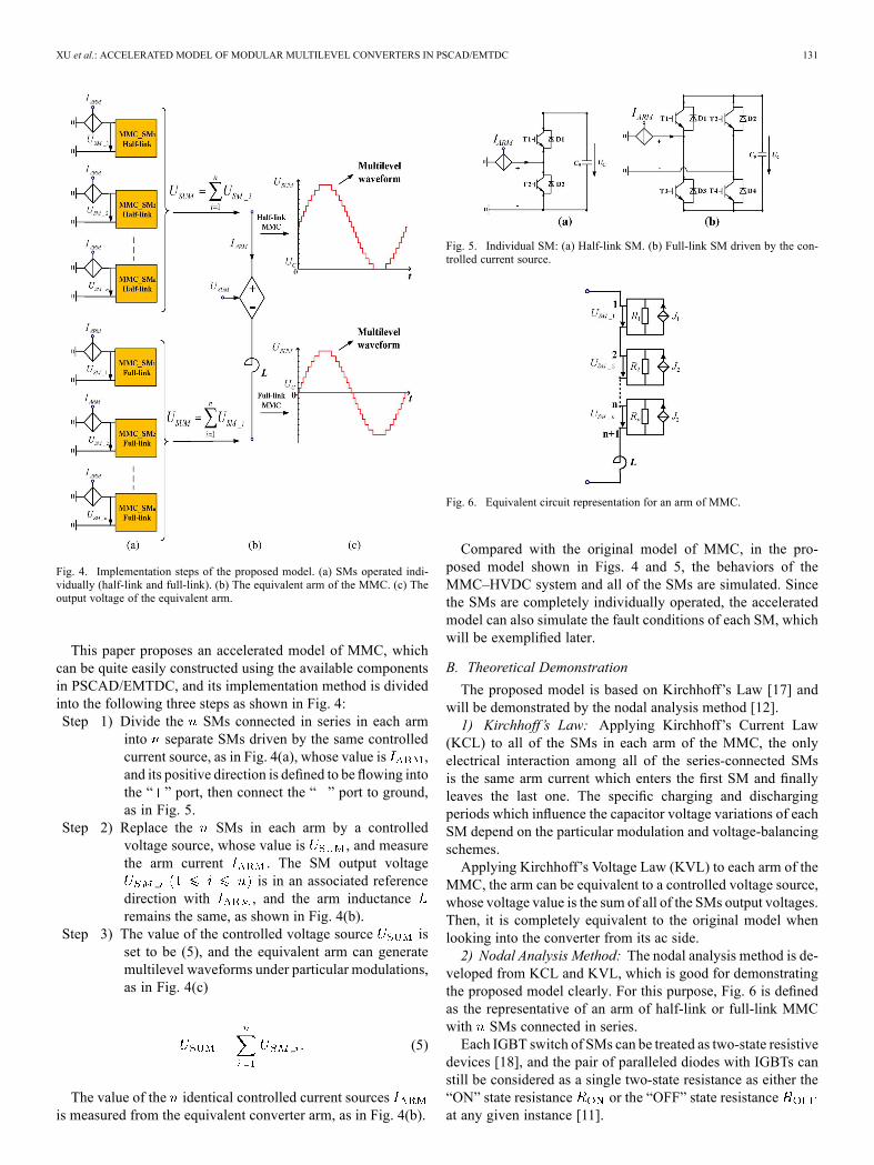
The value of the identical controlled current sourcesis measured from the equivalent converter arm, as in Fig. 4(b).
Fig. 5. Individual SM: (a) Half-link SM. (b) Full-link SM driven by the con-trolled current source.
Fig. 6. Equivalent circuit representation for an arm of MMC.
Compared with the original model of MMC, in the pro-posed model shown in Figs. 4 and 5, the behaviors of theMMC–HVDC system and all of the SMs are simulated. Sincethe SMs are completely individually operated, the acceleratedmodel can also simulate the fault conditions of each SM, whichwill be exemplified later.
B. Theoretical Demonstration
The proposed model is based on Kirchhoff’s Law [17] andwill be demonstrated by the nodal analysis method [12].1) Kirchhoff’s Law: Applying Kirchhoff’s Current Law
(KCL) to all of the SMs in each arm of the MMC, the onlyelectrical interaction among all of the series-connected SMsis the same arm current which enters the first SM and finallyleaves the last one. The specific charging and dischargingperiods which influence the capacitor voltage variations of eachSM depend on the particular modulation and voltage-balancingschemes.Applying Kirchhoff’s Voltage Law (KVL) to each arm of the
MMC, the arm can be equivalent to a controlled voltage source,whose voltage value is the sum of all of the SMs output voltages.Then, it is completely equivalent to the original model whenlooking into the converter from its ac side.2) Nodal Analysis Method: The nodal analysis method is de-
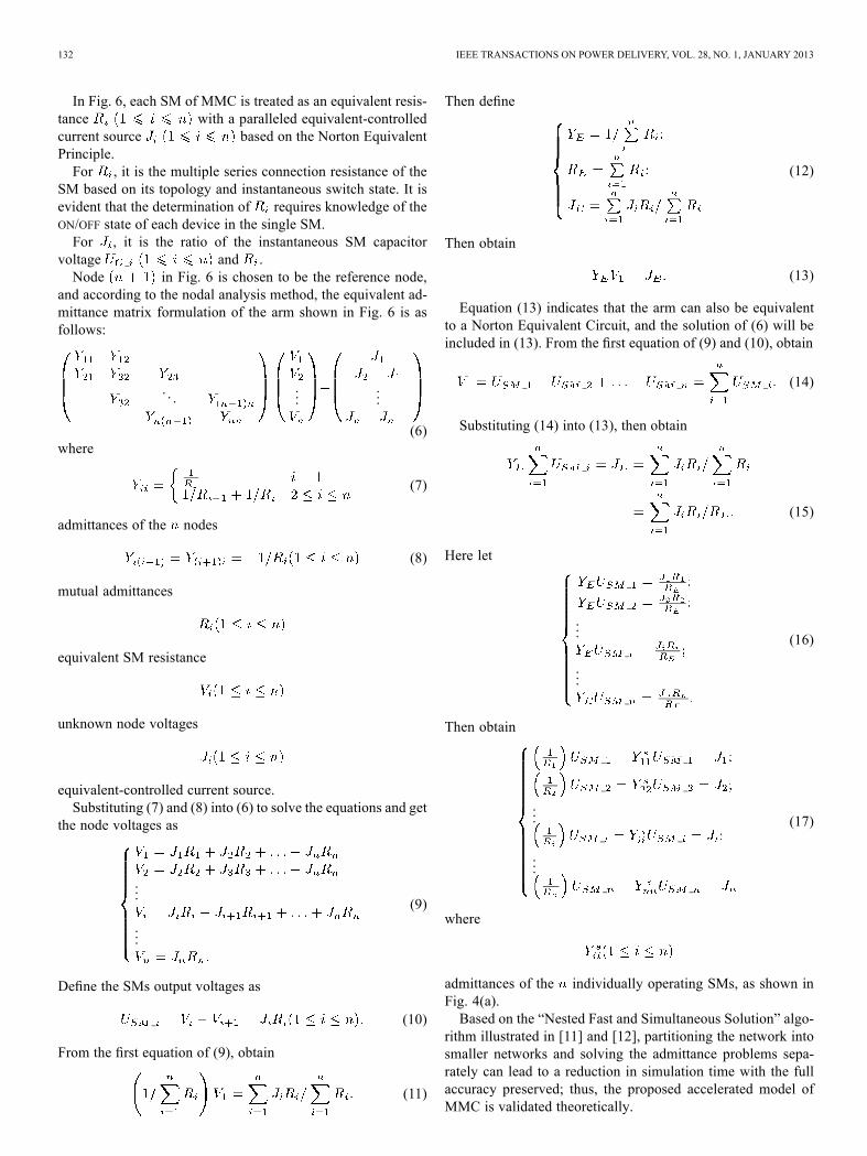
veloped from KCL and KVL, which is good for demonstratingthe proposed model clearly. For this purpose, Fig. 6 is definedas the representative of an arm of half-link or full-link MMCwith SMs connected in series.Each IGBT switch of SMs can be treated as two-state resistive
devices [18], and the pair of paralleled diodes with IGBTs canstill be considered as a single two-state resistance as either the“ON” state resistance or the “OFF” state resistanceat any given instance [11].
132 IEEE TRANSACTIONS ON POWER DELIVERY, VOL. 28, NO. 1, JANUARY 2013
In Fig. 6, each SM of MMC is treated as an equivalent resis-tance with a paralleled equivalent-controlledcurrent source based on the Norton EquivalentPrinciple.For , it is the multiple series connection resistance of the
SM based on its topology and instantaneous switch state. It isevident that the determination of requires knowledge of theON/OFF state of each device in the single SM.For , it is the ratio of the instantaneous SM capacitor
voltage and .Node in Fig. 6 is chosen to be the reference node,
and according to the nodal analysis method, the equivalent ad-mittance matrix formulation of the arm shown in Fig. 6 is asfollows:
. . ....
...
(6)where
(7)
admittances of the nodes
(8)
mutual admittances
equivalent SM resistance
unknown node voltages
equivalent-controlled current source.Substituting (7) and (8) into (6) to solve the equations and get
the node voltages as
...
...
(9)
Define the SMs output voltages as
(10)
From the first equation of (9), obtain
(11)
Then define
(12)
Then obtain
(13)
Equation (13) indicates that the arm can also be equivalentto a Norton Equivalent Circuit, and the solution of (6) will beincluded in (13). From the first equation of (9) and (10), obtain
(14)
Substituting (14) into (13), then obtain
(15)
Here let
...
...
(16)
Then obtain
...
...
(17)
where
admittances of the individually operating SMs, as shown inFig. 4(a).Based on the “Nested Fast and Simultaneous Solution” algo-
rithm illustrated in [11] and [12], partitioning the network intosmaller networks and solving the admittance problems sepa-rately can lead to a reduction in simulation time with the fullaccuracy preserved; thus, the proposed accelerated model ofMMC is validated theoretically.

XU et al.: ACCELERATED MODEL OF MODULAR MULTILEVEL CONVERTERS IN PSCAD/EMTDC 133
Fig. 7. Schematic diagrams of the modulation and capacitor voltage-balancingmodules of MMC.
It is worth noting that the theory analysis from before isindependent of the specific simulation environments, besidesPSCAD/EMTDC, platforms such as MATLAB will havethe similar simulation accuracy and acceleration effects. Inaddition, the proposed model can be easily extended to othercascaded multilevel converters, in a similar manner to thatillustrated in Figs. 4 and 5 of this paper.
IV. MODEL VALIDATION
With the modulation and voltage-balancing schemes ofMMC, the selection method of the maximum simulation timestep will be analyzed first and then the proposed model will bevalidated from accuracy and acceleration ratio aspects. Sincethe theoretical demonstration in Section III is universal forboth half-link and full-link MMCs, half-link MMC will betaken as being representative in this paper. The level of MMCvaries from 5 to 251 to compare the simulation accuracy andacceleration ratio of the proposed and original models.
A. Modulation and Voltage Balancing Schemes of MMC
MMC needs proper modulation and voltage-balancingschemes to output desired multilevel waveforms, and controlthe distributed capacitors voltages fluctuating with limits. Inthe following text, a single arm of MMC with NLM and thetraditional ordering method [11] will be discussed since the sixarms of MMC adopt the same schemes. Fig. 7 illustrates themodulation and capacitor voltage-balancing modules of MMC.1) Modulation Scheme: For the modulation module, the
exact number of SMs in service per arm is the ratio of the sinu-soidal modulation wave and the average value of the capacitorvoltages by the rounding function, which can be expressed asfollows:
(18)
where
average value of the capacitor voltages per arm;
reference dc-link voltage;
number of SMs per arm of MMC (withoutconsidering the redundancy SMs).
(19)
where
exact number of SMs in service per arm of MMC atan instance of time;
sinusoidal modulation wave of each arm of MMC.
Equation (19) indicates that each step of is anddifferent definitions of the rounding function will lead to a rel-ative error of half .2) Voltage-Balancing Scheme: For the capacitor voltage-
balancing module, the capacitor voltages magnitudesof the series-connected SMs
and the arm current in each arm of the MMC are mea-sured at the millisecond level. If this module is triggered at aspecific moment, the SMs are sorted in order of their voltagemagnitudes during a simulation time step, and generate thetriggering signals for the SMs,according to the time-varying and .If is charging the SMs, the bottom SMs of the
sorted list are turned on, so their voltages will increase, and theother SMs in the same arm will remain. If is dischargingthe SMs, the top SMs of the sorted list are turned on, sotheir voltages will decrease, and the other SMs in the same armwill remain.For the triggering time of the capacitor voltage-balancing
module, this paper realized two different triggering modes:Mode1: triggering the Module in each change of ; Mode2:triggering the Module with constant frequency, and the timeinterval between two contiguous pulses is defined as (20)
(20)
where
time interval between two contiguous triggeringpulses;
constant frequency for generating the triggeringpulses.
The alternative Mode2 makes the triggering frequency of thecapacitor voltage-balancing module controllable. By increasingthe switching frequencies of IGBTs, the SM voltages fluctua-tions can be limited to some extent. However, Mode2 is not in-volved in [11].For the purpose of distinguishing the directions of the arm
current, its reference direction has been defined in Section III, if, it is charging the SMs. If , it is discharging
the SMs. If , the following method using the historyarm current in the last simulation time step is proposed inthis paper:
134 IEEE TRANSACTIONS ON POWER DELIVERY, VOL. 28, NO. 1, JANUARY 2013
If , then deduce is charging the SMs. If, then deduce is discharging the SMs. The proposed de-duction method is based on the current maintaining function ofthe arm inductance .
B. Selection Method of Maximum Simulation Time Step
The simulation time step of MMC is vitally important andsensitive for testing the running time of the programs. For NLMbeing applied to MMC, the selection method of the maximumsimulation time step is theoretically illustrated in [19] fromwhich the following equation can be obtained:
(21)
where
maximum simulation time step;
minimum sampling frequency;
system fundamental frequency;
modulation index of MMC.
In order to preserve the simulation accuracy and output thedesired voltage levels, the necessary minimum sampling fre-quency can be calculated by (21), which indicates that as thevoltage level of MMC increases, the needed minimum samplingfrequency of the system increases; thus, the maximum simula-tion time step decreases.In this paper, as high as the 251 level of MMC (250 SMs per
arm) is modeled, set 60 Hz, 1.0, 250, and obtains. Then, the simulation time step is set to be 20
s, which is the same as that in [11] and easy for comparativeanalysis.
C. Validation of Accuracy
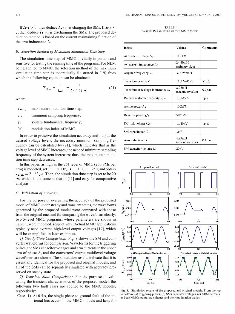
For the purpose of evaluating the accuracy of the proposedmodel ofMMCunder steady and transient states, the waveformsgenerated by the proposed model were compared with thosefrom the original one, and for comparing the waveforms clearly,two 5-level MMC programs, whose parameters are shown inTable I, were modeled, respectively. Actual MMC applicationstypically need extreme high-level output voltages [19], whichwill be exemplified in later examples.1) Steady-State Comparison: Fig. 8 shows the SM and con-
verter waveforms for comparison. Waveforms for the triggeringpulses, the SMs capacitor voltages and arm currents in the upperarm of phase A, and the converters’ output multilevel voltagewaveforms are shown. The simulation results indicate that it isessentially identical for the proposed and original models, andall of the SMs can be separately simulated with accuracy pre-served on steady state.2) Transient State Comparison: For the purpose of vali-
dating the transient characteristics of the proposed model, thefollowing two fault cases are applied to the MMC models,respectively:Case 1) At 0.5 s, the single-phase-to-ground fault of the in-
ternal bus occurs in the MMC models and lasts for
TABLE ISYSTEM PARAMETERS OF THE MMC MODEL
Fig. 8. Simulation results of the proposed and original models. From the topto bottom: (a) triggering pulses, (b) SMs capacitor voltages, (c) ARM currents,and (d) MMCs output ac voltages and their modulation waves.

XU et al.: ACCELERATED MODEL OF MODULAR MULTILEVEL CONVERTERS IN PSCAD/EMTDC 135
Fig. 9. Active and reactive power supplied from the MMCs on the transientstate: (a) proposed model, (b) original model.
Fig. 10. Output voltages of MMC under the triggering failure condition. (a)Proposed model. (b) Original model.
0.1 s and simulation ends at 1.0 s. The active and re-active power supplied from the MMCs is shown inFig. 9.
Case 2) At 0.5 s, an eternal single SM triggering failureoccurs in the upper arm of phase A of the MMCmodels, and simulation ends at 1.0 s. The outputvoltages of the MMCs under triggering failure con-ditions are shown in Fig. 10.
Figs. 9 and 10 indicate that the proposed model is capableof simulating the precise behaviors of the fault conditions, andsingle SM and the MMC-HVDC faults can be simulated in amanner identical to the original model.
D. Validation of Acceleration Ratio
The simulations of this paper were conducted on a MicrosoftWindows 7 Operating System with 3.20 GHz of Pentium(R)Dual-Core CPU, 2 GB of RAM running on the platform ofPSCAD/EMTDC version 4.2.1.In order to make the acceleration ratio of this paper compa-
rable with that presented in [11], single-phase MMC modelswith voltage levels varying from 5 to 251 were simulatedfor a duration of 1 s, with the simulation time step of 20 s.Table II tabulates the running time of the proposed and originalmodels and simulation ratios for different levels of MMC. It isworth noting that the compilation time of all the simulations inPSCAD/EMTDC is not taken into account of the running timein Table II.In Fig. 11, as the level of MMC increases, the original model
will have a running time which varies exponentially, and theproposed model will have a running time which varies linearly;thus, the acceleration ratio also changes exponentially, as shown
TABLE IIRUNNING TIME COMPARISON OF THE PROPOSED MODEL
Fig. 11. Running time of the proposed and original models.
Fig. 12. Acceleration ratio of the proposed and original models.
in Fig. 12. Also, it indicates that the proposed accelerated modelof MMC can significantly reduce the running time comparedwith the original model.Compared with the corresponding data presented in [11], the
acceleration ratios of the proposedmodel are smaller than that of[11] due to the different accelerated modeling methods of MMCillustrated in the two papers. However, the proposed model in

136 IEEE TRANSACTIONS ON POWER DELIVERY, VOL. 28, NO. 1, JANUARY 2013
this paper is much easier to realize than that in [11]. What ismore, even when both simulating the original models of MMC,the running time in [11] is still much less than that shown inTable II of this paper, which indicates that the configurationsof computers and programming methods of the researchers areboth important factors that will influence the comparison results.
V. CONCLUSION
In this paper, an accelerated model of the half-link and full-link MMCs is presented and validated. The greatest advantageof the proposed model is that it is quite easy to construct usingthe available components in PSCAD/EMTDC, there is no needfor redefinitions of the devices of MMC, and that it can signif-icantly reduce the computational time of MMC at a very highlevel, with the model accuracy preserved.The detailed implementation method of the accelerated
model and its mathematical demonstration were presented, andvalidations from the aspects of accuracy and acceleration ratiowere carried out in PSCAD/EMTDC.The generality of the theoretical analysis indicates that the
proposedmodel ofMMC can also be applied to other simulationplatforms, and can be easily extended to other cascaded multi-level converters.
REFERENCES[1] M. Saeedifard and R. Iravani, “Dynamic performance of a modular
multilevel back-to-back HVDC system,” IEEE Trans. Power Del., vol.25, no. 4, pp. 2903–2912, Oct. 2010.
[2] S. Rohner, S. Bernet, and M. Hiller, “Modulation, losses, and semicon-ductor requirements of modular multilevel converters,” IEEE Trans.Ind. Appl., vol. 57, no. 8, pp. 2633–2642, Aug. 2010.
[3] F. Z. Peng, W. Qian, and D. Cao, “Recent advances in multilevel con-verter/inverter topologies and applications,” in Proc. Int. Power Elec-tron. Conf., 2010, pp. 493–501.
[4] Y. Zhang, G. P. Adam, and T. C. Lim, “Voltage source converter inhigh voltage applications: Multilevel versus two-level converters,” inProc. 9th IET Int. Conf. AC and DC Power Transm., Oct. 2010, pp.1–5.
[5] B. Singh and B. K. Panigrahi, “Voltage regulation and power flow con-trol of VSC based HVDC system,” in Proc. Int. Conf. Power Electron.,Drives Energy Syst., Dec. 2006, pp. 1–6.
[6] H. Pang, G. Tang, and Z. He, “Evaluation of losses in VSC-HVDCtransmission system,” in Proc. IEEE Power Energy Soc. Gen.Meeting—Convers. Del. Elect. Energy in 21st Century, 2008, pp. 1–6.
[7] A. Lesnicar and R. Marquardt, “An innovative modular multilevel con-verter topology suitable for a wide power range,” presented at the IEEEPower Tech Conf., Bologna, Italy, 2003.
[8] G. Vassilios, D. Agelidis Georgios, and D. N. Flourentzou, “Recentadvances in high-voltage direct-current power transmission systems,”in Proc. IEEE Int. Conf. Ind. Technol., 2006, pp. 206–213.
[9] H. Akagi, S. Inoue, and T. Yoshii, “Control and performance of a trans-formerless cascade PWM STATCOM with star configuration,” IEEETrans. Ind. Appl., vol. 43, no. 4, pp. 1041–1049, Jul./Aug. 2007.
[10] S. P. Teeuwsen, “Simplified dynamic model of a voltage-sourced con-verter with modular multilevel converter design,” in Proc. IEEE PowerEnergy Soc. Power Syst. Conf. Expo., 2009, pp. 1–6.
[11] U. N. Gnanarathna, A. M. Gole, and R. P. Jayasinghe, “Efficient mod-eling of modular multilevel HVDC converters (MMC) on electromag-netic transient simulation programs,” IEEE Trans. Power Del., vol. 26,no. 1, pp. 316–324, Jan. 2011.
[12] K. Strunz and E. Carlson, “Nested fast and simultaneous solution fortime-domain simulation of integrative power-electric and electronicsystems,” IEEE Trans. Power Del., vol. 22, no. 1, pp. 277–287, Jan.2007.
[13] J. Debnath, W. K. Fung, A. Gole, and S. Filizadeh, “Simulation oflarge-scale electrical power networks on graphics processing units,”in Proc. IEEE Elect. Power Energy Conf., pp. 199–204.
[14] H. Akagi, “Classification, terminology, and application of the modularmultilevel cascade converter (MMCC),” in Proc. Int. Power Electron.Conf., 2010, pp. 508–515.
[15] M. Hagiwara and H. Akagi, “Control and experiment of pulsewidth-modulated modular multilevel converters,” IEEE Trans. Power Elec-tron., vol. 24, no. 7, pp. 1737–1746, Jul. 2009.
[16] E. Solas, G. Abad, and J. A. Barrena, “Modelling, simulation and con-trol of modular multilevel converter,” in Proc. 14th Int. Power Elec-tron. Motion Control Conf., 2010, pp. T2-90–T2-96.
[17] F. R. Quintela, R. C. Redondo, and N. R.Melchor, “A general approachto Kirchhoff’s Laws,” IEEE Trans. Educ., vol. 52, no. 2, pp. 273–278,May 2009.
[18] “PSCAD X4 User’s Guide,” Manitoba Res. Ctr., Winnipeg, MB,Canada.
[19] Q. Tu and Z. Xu, “Impact of sampling frequency on harmonic distortionformodular multilevel converter,” IEEE Trans. Power Del., vol. 26, no.1, pp. 298–306, Jan. 2011.
Jianzhong Xu (S’12) was born in Shanxi Province,China. He received the B.S. degree from North ChinaElectric Power University (NCEPU), Beijing, China,in 2009, where he is currently pursuing the Ph.D. de-gree in power system and its automation.His research field is HVDC and flexible ac trans-
mission systems.
Chengyong Zhao (M’05) was born in ZhejiangProvince, China. He received the B.S., M.S., andPh.D. degrees in power system and its automationfrom North China Electrical Power University, Bei-jing, China, in 1988, 1993, and 2001, respectively.Currently, he is Deputy Director of New Energy
Power Grid Institute in Electrical and Electronic En-gineering School, North China Electric Power Uni-versity, Beijing, China, “111” project member of “In-troducing Talents of Discipline to Universities Pro-gram” of the Ministry of Education and State Admin-
istration of Foreign Experts Affairs, and Commissioner of the Power QualitySpecialization Committee of China Power Supply Society. His fields of interestinclude HVDC, flexible ac transmission systems, and power quality.
Wenjing Liu was born in Tianjin, China. Shereceived the B.S. degree in power systems andits automation from North China Electric PowerUniversity, Beijing, China, in 2011, where she iscurrently pursuing the M.Sc. degree in power systemand its automation.Her research field is HVDC and flexible ac trans-
mission systems.
Chunyi Guo (S’09) was born in Shanxi, China.He received the B.S. and Ph.D. degrees in powersystem and its automation from North China ElectricPower University, Beijing, China, in 2007 and 2012,respectively.Currently , he is a Lecturer with North China Elec-
tric Power University, Beijing, China. His researchinterests include HVDC and flexible ac transmissionsystems.


![IEEE TRANSACTIONS ON POWER DELIVERY 1 Impact of … · IEEE TRANSACTIONS ON POWER DELIVERY 1 ... IEEE Standard C57.91-1995 [8] and IEC standard 60076-7 [9] ... Clause 7 and updated](https://img.pdfslide.us/doc/110x75/5b5a2e597f8b9a24038be089/ieee-transactions-on-power-delivery-1-impact-of-ieee-transactions-on-power-delivery.jpg)