Embed Size (px)
Citation preview
This article has been accepted for inclusion in a future issue of this journal. Content is final as presented, with the exception of pagination.
IEEE TRANSACTIONS ON POWER DELIVERY 1
International Surveys on Circuit-Breaker ReliabilityData for Substation and System Studies
Anton Janssen, Member, IEEE, Dirk Makareinis, and Carl-Ejnar Sölver
Abstract—Since the 1970s, CIGRE has conducted three world-wide surveys on high-voltage circuit-breaker (CB) reliability.The results of the last inquiry, published last year, are presentedand compared with those of the former inquiries. With a focuson the CB’s fundamental functions for the system, figures showthe growth in reliability during the past decades. The reliabilityis expressed in failure per 100 CB years (CBY) or per 10 000operating cycles for the relevant failure modes. The overall majorfailure rate improved largely from the first (1.58 per 100 CBY)to the second (0.67 per 100 CBY) to the third enquiry (0.30 per100 CBY). The failure rate increases with higher voltage classes;GIS CBs have been shown to be twice as reliable and live tankCBs twice as bad as the average failure rate. Although improved,the mechanical operating mechanism is still the subassemblyresponsible for most failures; besides, CBs applied for frequentswitching purposes show a higher failure rate than average.
Index Terms—Failure modes, high-voltage circuit breaker (CB),major failure, reliability data, reliability definitions, system relia-bility.
I. INTRODUCTION
F AST, selective and reliable fault clearing is a prerequisitefor an electric power system. One of important elements of
the protection system is the circuit breaker (CB). Under normalcircumstances, the CB has to carry the current and energize orde-energize sections of the high-voltage (HV) network. But atthe very moment that somewhere in the network a short circuitappears, the CB is the only high-voltage apparatus to protectthe network. If the short-circuit current is not cleared immedi-ately, the backup protection systems will trip a larger part of thenetwork, leading to an outage of more overhead lines, busbars,and substations. In such a case, the power supply for a largerarea will be interrupted. Moreover, the fault must be quickly re-moved since otherwise dynamic stability problems in the entirepower system may occur.Consequently, the requirements for CB performance and reli-
ability are very high. These requirements are not only imposedon new CBs but also on old CBs and determine the utility’smaintenance and life-management strategy. From the point ofview of reliability, distinction can be made between a failure of
Manuscript received March 28, 2013; revised June 27, 2013; accepted July20, 2013. Paper no. TPWRD-00360-2013.A. Janssen is with Liander, Arnhem 6812 AR, the Netherlands (e-mail: anton.
[email protected]).D. Makareinis is with Siemens Power Transmission Division, Berlin 13629,
Germany (e-mail: [email protected]).C.-E. Sölver is a consulting engineer for STRI, Ludvika SE-77131, Sweden
(e-mail: [email protected]).Digital Object Identifier 10.1109/TPWRD.2013.2274750
a CB that causes the cessation of one or more of its fundamentalfunctions (i.e., a so-called major failure, MF or MaF) and otherfailures (minor failures, mf or MiF) and defects. By definition[1], a defect is an imperfection in the state of an item (or inherentweakness) which can result in one or more failures of the itemitself or of another item under the specific service or environ-mental or maintenance conditions for a stated period of time.An MaF will result in an immediate change in the power
system operating conditions (e.g., the backup protective equip-ment being required to remove the fault), or will result inmandatory removal from service within 30 min for nonsched-uled maintenance [1].The CB’s fundamental functions (i.e., the lack of fundamental
functions: MaF) are as follows:• does not close or open on command;• closes or opens without command;• does not make or break the current;• fails to carry the current;• breakdown to earth or between poles;• breakdown across open pole (internal or external);• locked in open or closed position.Note that a difference is made between the mechanical re-
sponse of the CB (the first two items and the last item), the elec-trical functions (making, breaking, carrying the current), and thedielectric failures (breakdowns, including breakdowns acrossopen poles).Examples of MiF are:• air/hydraulic oil leakage in the operating mechanism;• small gas leakage due to corrosion or other causes;• change in functional characteristics.The functional characteristics may include closing and
opening times, travel characteristics, lock-out pressure levels,and automatic functions such as for pole discrepancy.Major failures are defined from the perspective of the CB fun-
damental functions, but from a system perspective, sometimessuch a failure does not interfere with the system fundamentalfunctions (e.g., does not open or close on an operator’s com-mand). Utilities therefore may face problems when linking theirfailure reporting, that is related to power interruption, directlyto the information defined by IEC, which is formulated from theapparatus’ perspective.
II. WORLDWIDE SURVEYS
Conseil International des Grands Réseaux Electriques(CIGRE) is the International Council on Large Electric Systems(www.cigre.org), that conducted three worldwide enquiries onhigh-voltage CB failures and defects in service. Forementioneddefinitions, functions, and failures have been established by
0885-8977 © 2013 IEEE
This article has been accepted for inclusion in a future issue of this journal. Content is final as presented, with the exception of pagination.
2 IEEE TRANSACTIONS ON POWER DELIVERY
CIGRE Working Group 13.06, later Working Group A3.06,responsible for the surveys. In the meantime, similar definitionsare used for other components and have been introduced in theIEC standards [1].
A. First Worldwide Inquiry
The first international survey covered failures and defects ofCBs with a rated voltage of 63 kV and above. During the survey,failures have been observed for four years (1974–1977), in total,77 892 CB years, put into service after 1963. At that time, dif-ferent arc extinguishing technologies have been included, butduring the statistical analysis of the failures, no further distinc-tion has been made between the technologies (air-blast, bulkoil, minimum oil, single and double pressure -gas, vacuum,etc.). A total of 102 utilities from 22 countries participated in theinquiry. By means of population cards and failure cards, the in-formation on service experience has been collected. Apart frominformation about failures, also information about maintenanceintervals, maintenance costs, and the number of switching op-erations has been collected (operating cycles).All information has been analyzed per voltage class (63–100
kV, 100–200 kV, 200–300 kV, 300–500 kV, 500 kV).Results from the survey and specific investigations have
been published in several professional organizations. The mostimportant publication was in Electra No. 79 (1981) [2]. Thestudies were the basis for new mechanical and environmentaltests on CBs, such as mechanical operation tests, with anincreased number of cycles, low/high temperature tests and ahumidity test.
B. Second Worldwide Survey
The second international inquiry had the same structure, butwas limited to single pressure -gas technology only. How-ever, a distinction has beenmade between different technologiesof the operating mechanism (hydraulic, pneumatic, spring) andits impact on the failure rates.Moreover, distinction has beenmade betweenmetal-enclosed
and nonmetal-enclosed CBs; equipment installed outdoors andindoors; and equipment put into service before and after January1, 1983. The survey was conducted during the years 1988–1991,and covered CBs put into service after 1977. The total popula-tion consisted of 70 708 CB-years from 132 utilities of 22 coun-tries. The main objectives were to see whether the reliability,especially the mechanical reliability, of CBs has improved andwhether maintenance intervals andmaintenance efforts have de-veloped in a profitable way. The final report has been publishedas CIGRE Technical Brochure 83 (1994) [3].
C. Third Worldwide Survey
The third inquiry covered service experience in the years2004–2007 and 281 090 CB-years from 83 utilities of 26 coun-tries and was again limited to single pressure technology.The population of the third inquiry differs quite substantiallyfrom the former two inquiries; a fact to be considered whenmaking comparisons. The inquiry was a part of a survey that
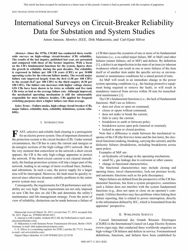
Fig. 1. Third inquiry application in the percentage of CB population.
covered the service experience with earthing switches, discon-nectors, instrument transformers, and gas-insulated switchgear(GIS) [4].The third inquiry included CBs of all ages, as a relation
between MaF-rate and age was an important objective of thethird survey. New was a distinction in CBs application (over-head line, cable, transformer, shunt reactor, shunt capacitor, buscoupler). More information has been asked about the enclosure,as a differentiation was made between dead-tank breakers,three-phase enclosed GIS, and single-phase enclosed GIS (seethe Appendix). Also, more details of dielectric failure modeswere asked, especially concerning its occurrence; that is, duringclosing/opening operation or during closed/open position. Theoutcome of the investigations on CB reliability in service isavailable as CIGRE Technical Brochure 510 (2012) [5].
III. POPULATION AND FAILURE STATISTICS
A. Applications
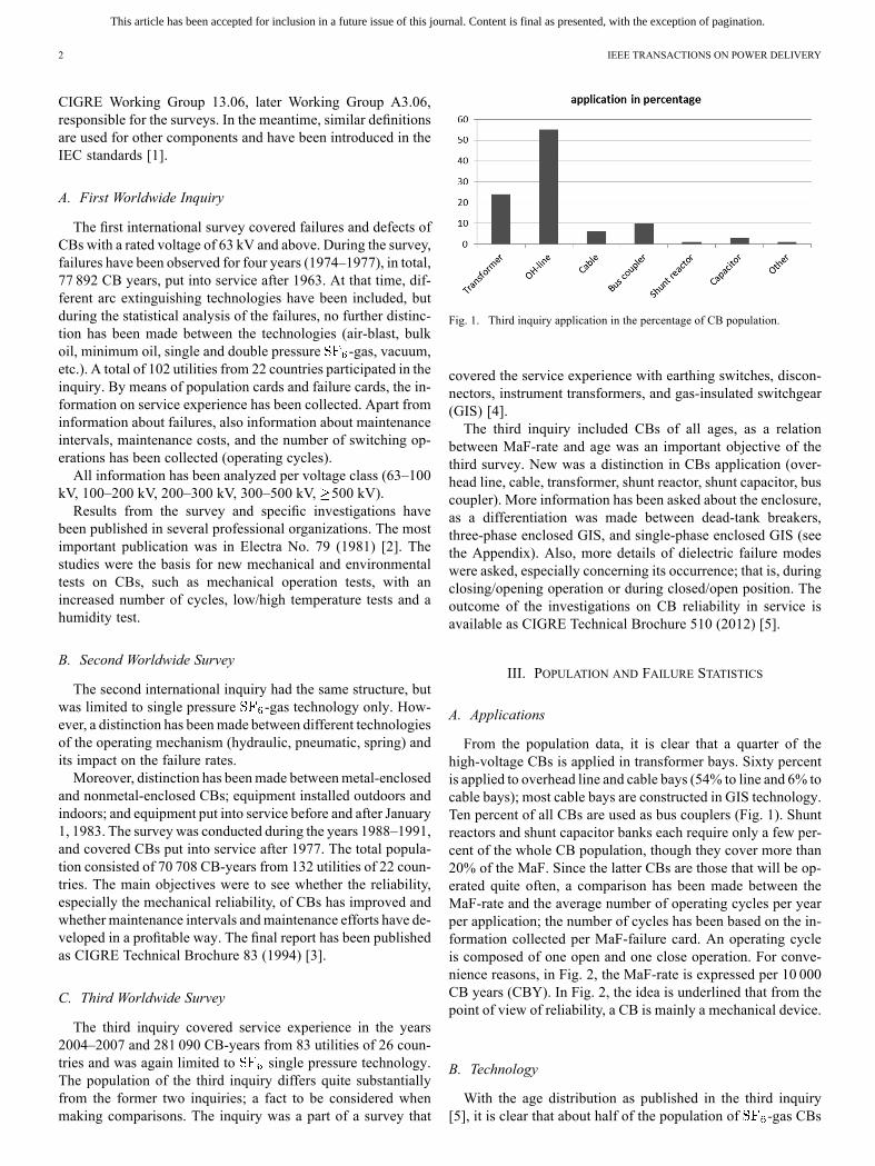
From the population data, it is clear that a quarter of thehigh-voltage CBs is applied in transformer bays. Sixty percentis applied to overhead line and cable bays (54% to line and 6% tocable bays); most cable bays are constructed in GIS technology.Ten percent of all CBs are used as bus couplers (Fig. 1). Shuntreactors and shunt capacitor banks each require only a few per-cent of the whole CB population, though they cover more than20% of the MaF. Since the latter CBs are those that will be op-erated quite often, a comparison has been made between theMaF-rate and the average number of operating cycles per yearper application; the number of cycles has been based on the in-formation collected per MaF-failure card. An operating cycleis composed of one open and one close operation. For conve-nience reasons, in Fig. 2, the MaF-rate is expressed per 10 000CB years (CBY). In Fig. 2, the idea is underlined that from thepoint of view of reliability, a CB is mainly a mechanical device.
B. Technology
With the age distribution as published in the third inquiry[5], it is clear that about half of the population of -gas CBs
This article has been accepted for inclusion in a future issue of this journal. Content is final as presented, with the exception of pagination.
JANSSEN et al.: INTERNATIONAL SURVEYS ON CB RELIABILITY DATA 3
Fig. 2. Third inquiry MaF rate and number of cycles per application.
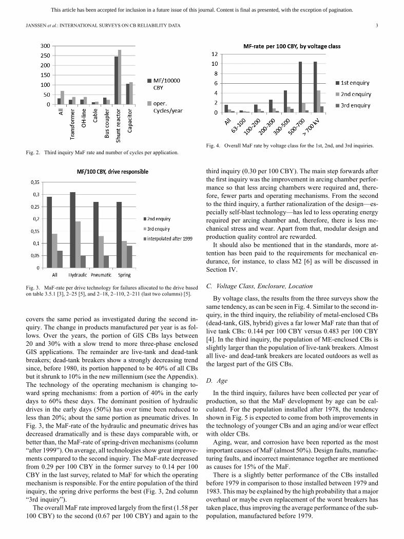
Fig. 3. MaF-rate per drive technology for failures allocated to the drive basedon table 3.5.1 [3], 2–25 [5], and 2–18, 2–110, 2–211 (last two columns) [5].
covers the same period as investigated during the second in-quiry. The change in products manufactured per year is as fol-lows. Over the years, the portion of GIS CBs lays between20 and 30% with a slow trend to more three-phase enclosedGIS applications. The remainder are live-tank and dead-tankbreakers; dead-tank breakers show a strongly decreasing trendsince, before 1980, its portion happened to be 40% of all CBsbut it shrunk to 10% in the new millennium (see the Appendix).The technology of the operating mechanism is changing to-ward spring mechanisms: from a portion of 40% in the earlydays to 60% these days. The dominant position of hydraulicdrives in the early days (50%) has over time been reduced toless than 20%; about the same portion as pneumatic drives. InFig. 3, the MaF-rate of the hydraulic and pneumatic drives hasdecreased dramatically and is these days comparable with, orbetter than, the MaF-rate of spring-driven mechanisms (column“after 1999”). On average, all technologies show great improve-ments compared to the second inquiry. The MaF-rate decreasedfrom 0.29 per 100 CBY in the former survey to 0.14 per 100CBY in the last survey, related to MaF for which the operatingmechanism is responsible. For the entire population of the thirdinquiry, the spring drive performs the best (Fig. 3, 2nd column“3rd inquiry”).The overall MaF rate improved largely from the first (1.58 per
100 CBY) to the second (0.67 per 100 CBY) and again to the
Fig. 4. Overall MaF rate by voltage class for the 1st, 2nd, and 3rd inquiries.
third inquiry (0.30 per 100 CBY). The main step forwards afterthe first inquiry was the improvement in arcing chamber perfor-mance so that less arcing chambers were required and, there-fore, fewer parts and operating mechanisms. From the secondto the third inquiry, a further rationalization of the design—es-pecially self-blast technology—has led to less operating energyrequired per arcing chamber and, therefore, there is less me-chanical stress and wear. Apart from that, modular design andproduction quality control are rewarded.It should also be mentioned that in the standards, more at-
tention has been paid to the requirements for mechanical en-durance, for instance, to class M2 [6] as will be discussed inSection IV.
C. Voltage Class, Enclosure, Location
By voltage class, the results from the three surveys show thesame tendency, as can be seen in Fig. 4. Similar to the second in-quiry, in the third inquiry, the reliability of metal-enclosed CBs(dead-tank, GIS, hybrid) gives a far lower MaF rate than that oflive tank CBs: 0.144 per 100 CBY versus 0.483 per 100 CBY[4]. In the third inquiry, the population of ME-enclosed CBs isslightly larger than the population of live-tank breakers. Almostall live- and dead-tank breakers are located outdoors as well asthe largest part of the GIS CBs.
D. Age
In the third inquiry, failures have been collected per year ofproduction, so that the MaF development by age can be cal-culated. For the population installed after 1978, the tendencyshown in Fig. 5 is expected to come from both improvements inthe technology of younger CBs and an aging and/or wear effectwith older CBs.Aging, wear, and corrosion have been reported as the most
important causes of MaF (almost 50%). Design faults, manufac-turing faults, and incorrect maintenance together are mentionedas causes for 15% of the MaF.There is a slightly better performance of the CBs installed
before 1979 in comparison to those installed between 1979 and1983. This may be explained by the high probability that a majoroverhaul or maybe even replacement of the worst breakers hastaken place, thus improving the average performance of the sub-population, manufactured before 1979.

This article has been accepted for inclusion in a future issue of this journal. Content is final as presented, with the exception of pagination.
4 IEEE TRANSACTIONS ON POWER DELIVERY
Fig. 5. Third inquiry MaF-rate per voltage class and by year of production.
TABLE IPERCENTAGE OF FAILURES RELATED TO THE SUBASSEMBLY AND
COMPONENT RESPONSIBLE, 2ND INQUIRY
E. Components
As reported in the first survey, half of the failures occurred inthe components at service voltage and one-third in the operatingmechanism. That changed with single pressure -gas tech-nology. The subassemblies and components responsible for theMaF give the same distribution for the third as for the second in-quiry. In Table I, details are given as reported for the second in-quiry with the operating mechanism being responsible for mostfailures, both major and minor failures. Minor failures have notbeen analyzed in absolute numbers, as with the third inquiry,based on the response per country, wide underreporting of themany MiF is assumed.
F. Failure Modes
The failure modes or failure characteristics are quite similarfor the second and the third inquiry. Since the third survey givesmore details, these failure modes are listed in Table II.Most failures occurred in the operating mechanism, fol-
lowed by the electrical control and auxiliary system (MaF) andhigh-voltage parts (MiF). The last item seems to be relatedto -gas tightness as the dominant MiF-mode is “Small
-gas leakage.” “Locked in open or closed position” isa dominant MaF—mode, that is mainly related to -gas
TABLE IIPERCENTAGE OF MAF RATE AND MIF RATE PER
FAILURE MODE, THIRD INQUIRY
tightness. It is also related to the operating mechanism andthe electric control system. These two subassemblies led tofailure modes, such as “Does not open or close on command”;consuming 45% of MaF. With “Locked in open or closedposition,” it sums up to 70% of MaF. As expected, the MaFrate with the mode “Does not open or close on command” isproportional to the number of operating cycles per year andwith “Locked in open or closed position,” the relationship ismore indifferent, although a light proportionality can be seen(table 2–57 [5]).Another 10% of MaF is for dielectric breakdowns and al-
most 10% for loss of mechanical integrity. Four percent of theMaF (6.5% in the second enquiry) resulted in an explosion orfire; mainly in relation to dielectric breakdowns and mainly withlive-tank breakers. There is an intriguing distribution of the ex-plosions among the applications of the CB (Fig. 6). CBs appliedin transformer bays seem to perform well, while CBs applied toswitch shunt reactors and capacitor banks show a higher explo-sion risk. However, it should be noted that the probability of anexplosion is 0.01 per 100 CBY for the entire population.Only a small part of the major failures has the characteristic
“Does not break the current”: 1.9% or 0.006 per 100 CBY. Sothe mechanical performance seems to need the most attentionfrom the point of view of reliability. However, the probabilitythat a CB has to interrupt, for instance, a short-line fault, is or-ders of magnitude lower than the frequency of regular operating
This article has been accepted for inclusion in a future issue of this journal. Content is final as presented, with the exception of pagination.
JANSSEN et al.: INTERNATIONAL SURVEYS ON CB RELIABILITY DATA 5
Fig. 6. Third inquiry subpopulations and explosions per application in percent.
Fig. 7. Third inquiry MaF-rate per failure mode including the fire/explosionrate.
cycles. Still, reliable fault clearing is a very important duty of aCB, depending both on its capability to interrupt fault currentsand its reliability to “Open and close on command.”
IV. MECHANICAL ENDURANCE
At the first and second international inquiry, a number ofquestions have been put forward about the number of operatingcycles per year. The outcome showed that 90% of the CBs areasked upon to perform 80 operating cycles (one open and oneclose operation) per year or less (i.e., the 90% percentile of thenumber of operating cycles per year [2], [3]).The average number of operating cycles per year from the
second inquiry was higher than that from the first inquiry: 42versus 26.5 CO-operations per year.The reason for the difference is that in the first inquiry, the
average has been determined by weighting each answer on thepopulation cards equally and in the second inquiry, each answerhas been weighted by the number of related CBs [7]. At the thirdinternational inquiry, the average number of operating cycleshas not been collected, but could be estimated roughly by theinformation per the MaF report. The analysis reported in [5]gives an average of 69 operating cycles per year, far more thanthe 42 found with the second survey.
However, this is the average of the answers per MaF-card andthese answers have been differentiated per application, as shownin Fig. 1 (i.e., tables 2–59 and 2–60 of [5]). By using the aver-ages per application (table 2–60 of [5]), multiplying them bythe number of CB-years reported for that application (table 2–5[5]) and dividing the outcome by the total population in CBY,the total average becomes 42 operating cycles per year; exactlythe same number as with the second inquiry. Furthermore, thereare no circumstances why the average number of cycles per yearshould have been changed, or anyways increased, from inquiryto inquiry.Based on these results for a 25-year period of service, these
days seen as the interval between major overhaul, the majorityof CBs has to perform 2000 operating cycles or less. Therefore,the mechanical endurance type test in the standards has beenspecified as 2000 operating cycles or operating sequences, as iscalled in the IEC standards. That is to say for CBs applied tonormal service conditions, class M1. For special applications,such as shunt reactor switching, an extended mechanical en-durance-type test with 10 000 CO-cycles has been specified inIEC Standard 62271-100 [6]: class M2.The mechanical endurance-type test is relatively easy to per-
form and gives a very good quality check. Without energizingthe high-voltage parts, the required number of operating cy-cles is performed under varying conditions of auxiliary voltageand operating pressure. Maintenance has to be performed to themanufacturer’s instructions; that is, according to the manual.These days, maintenance during 2000 CO operations will be nil.The mechanical, dielectric, and electrical characteristics afterthe endurance test have to be identical to those before the testor at least within the tolerances as stated in the manual. This ap-plies for the primary contacts as well as the auxiliary contacts.
-tightness also has to be checked.For reliability assessment and to investigate the weak spots
and endurance limits, manufacturers will test prototypes andsubassemblies to a much larger number of cycles; up to tens ofthousands. Such development tests will give proper informationabout maintenance intervals and actions [8].The widely accepted hypothesis is that as long as the mechan-
ical behavior of a CB is identical to that of the type tested sampleand the -gas density is within the operating tolerances, theCB will perform as specified in the standards. Maintenance istherefore mainly focused on the mechanical characteristics.
V. SUBSTATION AND SYSTEM RELIABILITY STUDIES
The results of the CB reliability studies are also valuable forsubstation and system reliability investigations. In [7], the in-formation of the first and second inquiry has been used to cal-culate per voltage class the number of MaFs per command toopen/close and the number of other MaFs per year. For substa-tion and system reliability studies, such a distinction is neces-sary, as reliability engineers want to know the probability of afailure per command (especially for protection functions) andper time period. The same approach will be followed to cal-culate the MaF rates with the information of the third world-wide inquiry. But since no information about failure modes per
This article has been accepted for inclusion in a future issue of this journal. Content is final as presented, with the exception of pagination.
6 IEEE TRANSACTIONS ON POWER DELIVERY
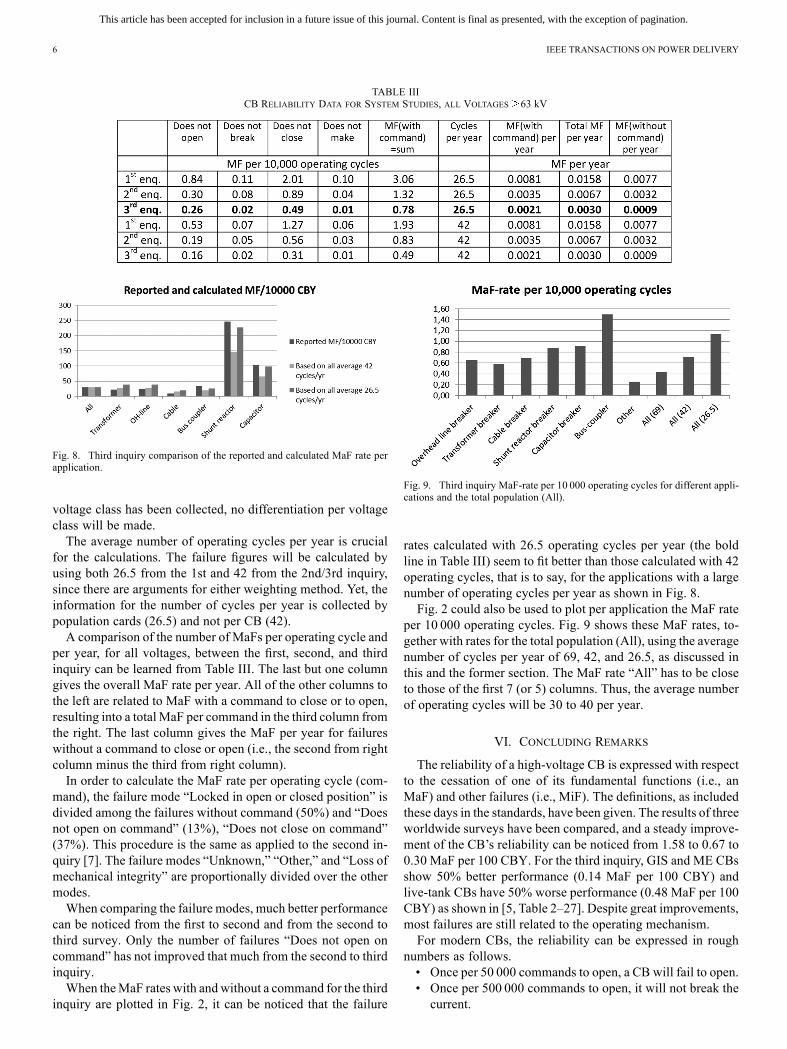
TABLE IIICB RELIABILITY DATA FOR SYSTEM STUDIES, ALL VOLTAGES 63 kV
Fig. 8. Third inquiry comparison of the reported and calculated MaF rate perapplication.
voltage class has been collected, no differentiation per voltageclass will be made.The average number of operating cycles per year is crucial
for the calculations. The failure figures will be calculated byusing both 26.5 from the 1st and 42 from the 2nd/3rd inquiry,since there are arguments for either weighting method. Yet, theinformation for the number of cycles per year is collected bypopulation cards (26.5) and not per CB (42).A comparison of the number of MaFs per operating cycle and
per year, for all voltages, between the first, second, and thirdinquiry can be learned from Table III. The last but one columngives the overall MaF rate per year. All of the other columns tothe left are related to MaF with a command to close or to open,resulting into a totalMaF per command in the third column fromthe right. The last column gives the MaF per year for failureswithout a command to close or open (i.e., the second from rightcolumn minus the third from right column).In order to calculate the MaF rate per operating cycle (com-
mand), the failure mode “Locked in open or closed position” isdivided among the failures without command (50%) and “Doesnot open on command” (13%), “Does not close on command”(37%). This procedure is the same as applied to the second in-quiry [7]. The failure modes “Unknown,” “Other,” and “Loss ofmechanical integrity” are proportionally divided over the othermodes.When comparing the failure modes, much better performance
can be noticed from the first to second and from the second tothird survey. Only the number of failures “Does not open oncommand” has not improved that much from the second to thirdinquiry.When theMaF rates with andwithout a command for the third
inquiry are plotted in Fig. 2, it can be noticed that the failure
Fig. 9. Third inquiry MaF-rate per 10 000 operating cycles for different appli-cations and the total population (All).
rates calculated with 26.5 operating cycles per year (the boldline in Table III) seem to fit better than those calculated with 42operating cycles, that is to say, for the applications with a largenumber of operating cycles per year as shown in Fig. 8.Fig. 2 could also be used to plot per application the MaF rate
per 10 000 operating cycles. Fig. 9 shows these MaF rates, to-gether with rates for the total population (All), using the averagenumber of cycles per year of 69, 42, and 26.5, as discussed inthis and the former section. The MaF rate “All” has to be closeto those of the first 7 (or 5) columns. Thus, the average numberof operating cycles will be 30 to 40 per year.
VI. CONCLUDING REMARKS
The reliability of a high-voltage CB is expressed with respectto the cessation of one of its fundamental functions (i.e., anMaF) and other failures (i.e., MiF). The definitions, as includedthese days in the standards, have been given. The results of threeworldwide surveys have been compared, and a steady improve-ment of the CB’s reliability can be noticed from 1.58 to 0.67 to0.30 MaF per 100 CBY. For the third inquiry, GIS and ME CBsshow 50% better performance (0.14 MaF per 100 CBY) andlive-tank CBs have 50% worse performance (0.48 MaF per 100CBY) as shown in [5, Table 2–27]. Despite great improvements,most failures are still related to the operating mechanism.For modern CBs, the reliability can be expressed in rough
numbers as follows.• Once per 50 000 commands to open, a CB will fail to open.• Once per 500 000 commands to open, it will not break thecurrent.
This article has been accepted for inclusion in a future issue of this journal. Content is final as presented, with the exception of pagination.
JANSSEN et al.: INTERNATIONAL SURVEYS ON CB RELIABILITY DATA 7
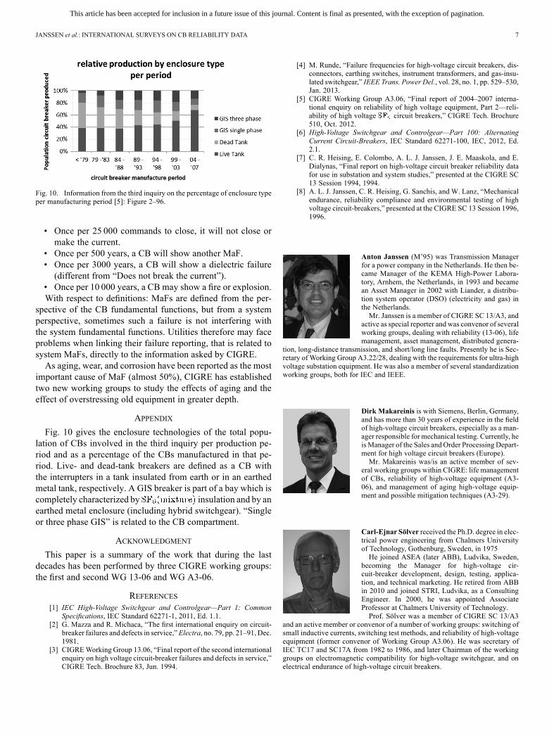
Fig. 10. Information from the third inquiry on the percentage of enclosure typeper manufacturing period [5]: Figure 2–96.
• Once per 25 000 commands to close, it will not close ormake the current.
• Once per 500 years, a CB will show another MaF.• Once per 3000 years, a CB will show a dielectric failure(different from “Does not break the current”).
• Once per 10 000 years, a CB may show a fire or explosion.With respect to definitions: MaFs are defined from the per-
spective of the CB fundamental functions, but from a systemperspective, sometimes such a failure is not interfering withthe system fundamental functions. Utilities therefore may faceproblems when linking their failure reporting, that is related tosystem MaFs, directly to the information asked by CIGRE.As aging, wear, and corrosion have been reported as the most
important cause of MaF (almost 50%), CIGRE has establishedtwo new working groups to study the effects of aging and theeffect of overstressing old equipment in greater depth.
APPENDIX
Fig. 10 gives the enclosure technologies of the total popu-lation of CBs involved in the third inquiry per production pe-riod and as a percentage of the CBs manufactured in that pe-riod. Live- and dead-tank breakers are defined as a CB withthe interrupters in a tank insulated from earth or in an earthedmetal tank, respectively. A GIS breaker is part of a bay which iscompletely characterized by insulation and by anearthed metal enclosure (including hybrid switchgear). “Singleor three phase GIS” is related to the CB compartment.
ACKNOWLEDGMENT
This paper is a summary of the work that during the lastdecades has been performed by three CIGRE working groups:the first and second WG 13-06 and WG A3-06.
REFERENCES[1] IEC High-Voltage Switchgear and Controlgear—Part 1: Common
Specifications, IEC Standard 62271-1, 2011, Ed. 1.1.[2] G. Mazza and R. Michaca, “The first international enquiry on circuit-
breaker failures and defects in service,”Electra, no. 79, pp. 21–91, Dec.1981.
[3] CIGREWorking Group 13.06, “Final report of the second internationalenquiry on high voltage circuit-breaker failures and defects in service,”CIGRE Tech. Brochure 83, Jun. 1994.
[4] M. Runde, “Failure frequencies for high-voltage circuit breakers, dis-connectors, earthing switches, instrument transformers, and gas-insu-lated switchgear,” IEEE Trans. Power Del., vol. 28, no. 1, pp. 529–530,Jan. 2013.
[5] CIGRE Working Group A3.06, “Final report of 2004–2007 interna-tional enquiry on reliability of high voltage equipment, Part 2—reli-ability of high voltage circuit breakers,” CIGRE Tech. Brochure510, Oct. 2012.
[6] High-Voltage Switchgear and Controlgear—Part 100: AlternatingCurrent Circuit-Breakers, IEC Standard 62271-100, IEC, 2012, Ed.2.1.
[7] C. R. Heising, E. Colombo, A. L. J. Janssen, J. E. Maaskola, and E.Dialynas, “Final report on high-voltage circuit breaker reliability datafor use in substation and system studies,” presented at the CIGRE SC13 Session 1994, 1994.
[8] A. L. J. Janssen, C. R. Heising, G. Sanchis, and W. Lanz, “Mechanicalendurance, reliability compliance and environmental testing of highvoltage circuit-breakers,” presented at the CIGRE SC 13 Session 1996,1996.
Anton Janssen (M’95) was Transmission Managerfor a power company in the Netherlands. He then be-came Manager of the KEMA High-Power Labora-tory, Arnhem, the Netherlands, in 1993 and becamean Asset Manager in 2002 with Liander, a distribu-tion system operator (DSO) (electricity and gas) inthe Netherlands.Mr. Janssen is a member of CIGRE SC 13/A3, and
active as special reporter and was convenor of severalworking groups, dealing with reliability (13-06), lifemanagement, asset management, distributed genera-
tion, long-distance transmission, and short/long line faults. Presently he is Sec-retary of Working Group A3.22/28, dealing with the requirements for ultra-highvoltage substation equipment. He was also a member of several standardizationworking groups, both for IEC and IEEE.
Dirk Makareinis is with Siemens, Berlin, Germany,and has more than 30 years of experience in the fieldof high-voltage circuit breakers, especially as a man-ager responsible for mechanical testing. Currently, heisManager of the Sales and Order Processing Depart-ment for high voltage circuit breakers (Europe).Mr. Makareinis was/is an active member of sev-
eral working groups within CIGRE: life managementof CBs, reliability of high-voltage equipment (A3-06), and management of aging high-voltage equip-ment and possible mitigation techniques (A3-29).
Carl-Ejnar Sölver received the Ph.D. degree in elec-trical power engineering from Chalmers Universityof Technology, Gothenburg, Sweden, in 1975He joined ASEA (later ABB), Ludvika, Sweden,
becoming the Manager for high-voltage cir-cuit-breaker development, design, testing, applica-tion, and technical marketing. He retired from ABBin 2010 and joined STRI, Ludvika, as a ConsultingEngineer. In 2000, he was appointed AssociateProfessor at Chalmers University of Technology.Prof. Sölver was a member of CIGRE SC 13/A3
and an active member or convenor of a number of working groups: switching ofsmall inductive currents, switching test methods, and reliability of high-voltageequipment (former convenor of Working Group A3.06). He was secretary ofIEC TC17 and SC17A from 1982 to 1986, and later Chairman of the workinggroups on electromagnetic compatibility for high-voltage switchgear, and onelectrical endurance of high-voltage circuit breakers.

![AKR 3/(R) A3 - AKR 4/(R) A3 - akarasansor.comR)_A3_20160209_103327.pdf · $ +ó] 5HJ¾ODW¸U¾ AKR 3/(R) A3 - AKR 4/(R) A3 AKR 4/(R) A3 AKR 3/(R) A3 $ * 9(1/ . 67$1'$57 + A3 SAFETY](https://img.pdfslide.us/doc/110x75/5ecc1d0dd33b5279e8267d6d/akr-3r-a3-akr-4r-a3-ra320160209103327pdf-5hjodwu-akr.jpg)