Embed Size (px)
Citation preview

2428 IEEE TRANSACTIONS ON POWER DELIVERY, VOL. 28, NO. 4, OCTOBER 2013
Field-Validated Load Model for the Analysisof CVR in Distribution Secondary Networks:
Energy ConservationMarc Diaz-Aguiló, Julien Sandraz, Richard Macwan, Francisco de León, Senior Member, IEEE,
Dariusz Czarkowski, Member, IEEE, Christopher Comack, Member, IEEE, and David Wang, Senior Member, IEEE
Abstract—This paper presents a field-validated load modelfor the calculation of the energy conservation gains due to con-servation voltage reduction (CVR) in highly meshed secondarynetworks. Several networks in New York City are modeled indetail. A time resolution of one hour is used to compute theenergy savings in a year. A total of 8760 power flow runs peryear for voltage reductions of 0%, 2.25%, 4%, 6%, and 8% fromthe normal schedule are computed. An equivalent ZIP modelis obtained for the network for active and reactive powers. Themost important finding is that voltage reductions of up to 4%can be safely implemented in the majority of the New York Citynetworks, without the need of investments in infrastructure. Thenetworks under analysis show CVR factors between 0.5 and 1 foractive power and between 1.2 and 2 for reactive power, leadingto the conclusion that the implementation of CVR will provideenergy and economic savings for the utility and the customer.
Index Terms—Conservation voltage optimization (CVO), con-servation voltage reduction (CVR), load model, system losses re-duction, ZIP coefficients model.
I. INTRODUCTION
C ONSERVATION of energy in distribution systems is atthe top of the list of issues that power utilities face today.
Conservation voltage reduction (CVR) is known as a methodof energy conservation by reducing voltage at the substationlevel [1]. CVR has been studied at different utilities with in-consistent results since its success depends on the nature of theload and the topology of the network. Constant impedance loadsare better suited for CVR than motor loads demanding constantpower. The CVR factor ( ) is used to determine how ef-fective CVR is for a particular system. It is calculated from thepercent energy savings divided by the percent voltage reduction.The same factor can be defined for reactive power ( ),calculated from the percent of reactive power reduction by thepercent of voltage reduction.
Manuscript received December 18, 2012; revised March 13, 2013; acceptedJune 20, 2013. Date of publication July 18, 2013; date of current versionSeptember 19, 2013. Paper no. TPWRD-01379-2012.M. Diaz-Aguiló, J. Sandraz, R. Macwan, F. de León, and D. Czarkowski,
are with the Department of Electrical and Computer Engineering, PolytechnicInstitute of New York University, Brooklyn, NY 11201 USA (e-mail: [email protected]; [email protected]; [email protected];[email protected]; [email protected]).C. Comack and D. Wang are with Consolidated Edison Inc., New York, NY
10003 USA (e-mail: [email protected]; [email protected]).Color versions of one or more of the figures in this paper are available online
at http://ieeexplore.ieee.org.Digital Object Identifier 10.1109/TPWRD.2013.2271095
A. History of CVR
Conservation voltage reduction has been in use as a techniquefor reducing energy consumption for a long time. Many utilitiesand public service commissions have tested and tried to imple-ment CVR on their system; see, for example, [2]–[4]. The firstwide-scale implementation of CVR was in 1973, during the oilembargo, when the Public Service Commission of New Yorkordered its utilities to implement 3%–5% reduction in voltagein order to reduce energy consumption [5]. However, in 1974,the order was lifted and the effects of CVR were not properlydocumented. Since then, many utilities have tried to implementCVR on their system using different strategies. The results ofthese studies vary widely and, so far, there has been only onedocumented case of successful system-wide implementation, byBC Hydro [6].The reported results in [6] show almost 1.3 GWh ( ) of
reduction in energy per year, while the peak demand was re-duced by 1.6 MW (1.1%), for a 1% voltage reduction. Utilitiesother than BC Hydro have also reported savings in energy usingCVR. In 1973, American Electric Power (AEP) conducted itsown study on CVR and found 3%–4% reduction in demand [7].However, the investment cost for the implementation of CVRwas not justified against the savings at that time. Also, Cal-ifornia PUC in 1976 reported savings of 2,686 GWh (1.7%)on their system for one year [1], based also on a 1% voltagereduction.More recently, in 2005, Hydro-Quebec implemented a pilot
project for CVR and reported close to 1.5 TWh (0.4% for 1%voltage reduction) of reduction in energy on its system [8]. Arecent simulation study by the Department of Energy in 2010also shows a reduction in annual energy of 3.04%. However,this simulation study does not show any substantial decrease inlosses [8].
B. Implementation and Advantages of CVR
When implementing CVR, the voltage at the customer termi-nals is reduced within appropriate limits to prevent damage toany sensitive appliances or equipment. According to ANSI stan-dards [9], service voltage must be at a minimum of 114 V, whichis 5% below 120 V and utilization voltage, under contingency,must be at a minimum of 108 V which is 10% below nominalvoltage.There are two methods for the implementation of CVR that
have been considered in the past [10]. The first is through linedrop compensation (LDC), by adjusting underload tap changers(ULTCS) (or other voltage controllers) such that the end of the
0885-8977 © 2013 IEEE

DIAZ-AGUILÓ et al.: FIELD-VALIDATED LOAD MODEL FOR THE ANALYSIS OF CVR 2429
line voltage is set at the desired lower voltage. ULTC trans-formers have controls that use an and an setting to createa model for the impedance of the feeder. Based upon the cur-rent or load, the voltage at the substation is calculated usingthe model so that the end of the line voltage is held at a spe-cific minimum voltage. The controller adjusts the tap positionon the transformer to hold end-of-line voltage at a set point. Theend-of-line voltage is not directly measured with this technique,but is calculated based on the model. The settings of the LDChave to be updated for each voltage reduction level. The secondmethod is voltage spread reduction (VSR), in which the limit isnarrowed to a smaller percentage change via regulators or ULTCcontrols. Usually, with this technique, somemodifications to thesystem are necessary. Distribution lines may need capacitors tocorrect power factor and maintain voltage profile, reconducting,or other changes.A newer method, adaptive voltage control (AVC) uses au-
tomatic control and communications to control the voltage atthe substation [11]. Its main components are a substation datacollector and controller (SDCC), an adaptive voltage controller(AVC), a line voltage monitor (LVM), and a voltage regulator.The SDCC monitors feeder kilowatt-hours, kvarh, kilowatts,kvar, current, and voltage. The AVC unit runs an algorithm andcommunicates with the LVM and possible line regulator inter-face units to obtain real-time data from the end of the line, crit-ical loads, or locations that may be known to have low voltage.The AVC unit then controls the voltage regulator or ULTC toadjust voltage to a set voltage point in order to maintain min-imum end-of-line voltage.The expected advantages of CVR in highly meshed sec-
ondary networks are numerous. Due to the stiffness of themesh topology, reduced or no investments are expected whenimplementing CVR. First of all, there are direct consequences,such as a reduction of power demand during peak periodsand accumulated energy savings during the complete year.This is also directly linked to a reduction of carbon emissions.Moreover, with reduced voltages, transformer life is extendedsince iron losses are a function of voltage [12]. Especiallyduring peak demand where there is a significant amount ofstress on the system, CVR may be a way to reduce this strainand potentially prevent outages. Energy consumption is on anupward trend and is projected to continue in this manner. CVRcould potentially delay the building of new powerplants orsystem reinforcements by offsetting the increased demand.In this paper, the feasibility and the possible benefits of the
implementation of CVR in the New York City networks oper-ated by Consolidated Edison, Inc. are investigated. This anal-ysis is performed for each of the 8760 hours in a year. A preciseanalysis on losses, voltage distribution, voltage violations, andactive/reactive power demand reduction is undertaken. Theseanalyses are year-wide and for particular load situations. Suchan extensive study for power systems with highly meshed sec-ondary distribution networks, like the New York City networks,has never been reported.
II. NETWORK MODELING
New York City’s electrical system represents a unique casestudy because of the widespread use of highly meshed sec-ondary networks. Secondary networks are used by utilities in
the core of cities, but the majority of distribution systems in theU.S. are radial [12]. This study uses real data from ConsolidatedEdison Inc. of New York. The network models are built usingthe known physical characteristics of each network, such as:cable impedances, transformer reactances, connectivity, preciselocation of each load, and even daily load variation by customerclasses during the year.For each network under study, a five-step procedure has been
followed: 1) processing of the raw data files; 2) translationof all network characteristics and topology into OpenDSS; 3)validation of the load-flow results with respect to ConsolidatedEdison’s internal load-flow program; 4) construction of theyearly load shapes for each of the customers of the network;and 5) running the CVR study on OpenDSS.
A. Topology of the Network
The topology of the different networks under study hasbeen built using: 1) characteristics and ratings of all areasubstation transformers; 2) characteristics and ratings of allprimary feeders and their connectivity; 3) characteristics andratings of all network transformers and their connections; 4)characteristics and ratings of all secondary feeders; and 5)yearly load values, their - and - characteristics and theirconnection points to the secondary mesh. The switches havebeen maintained with their default status or control logic.These models have been translated into OpenDSS input files.
OpenDSS is an electrical system simulation software devel-oped by EPRI [13]. In 2008, EPRI released the software underopen-source license to encourage grid modernization efforts inthe “smart grid” field. OpenDSS was designed mainly for con-ducting yearly load-flow simulations and, hence, is suitable forthis study. The area substation transformers are modeled as two-winding transformers with 0.1% no-load losses. Primary feedersand secondary cables are modeled as standard pi sections. Thenetwork transformers are also modeled as two-winding trans-formers with their known no-load loss. Finally, the loads con-nected at the secondary mesh are modeled as ZIP loads thatrepresent the - and - behavior of each customer class[14], [15]. These load models have been obtained from manyvoltage reduction tests performed in our laboratory on manydomestic appliances. These load models are further describedin Section III.
B. Voltage Regulator, Capacitor Switching, and NetworkProtectors
The voltage in the secondary networks is controlled from thearea substation ULTCs, which are operated with line-drop com-pensation mechanisms. The voltage reduction levels for eachnetwork are given in the voltage schedule specifications, whichare followed by the network operators. The operation of theULTCs has been mimicked in the OpenDSS model through avoltage schedule that properly reproduces the hourly voltagevariation during the day and year.Capacitors are connected and disconnected everyday to cor-
rect power factor and release transformer capacity. The actualcapacitor switching sequences have been included in the model.The operation of the network protectors is represented in de-
tail in the load-flow simulations. When reverse power is sensed,

2430 IEEE TRANSACTIONS ON POWER DELIVERY, VOL. 28, NO. 4, OCTOBER 2013
Fig. 1. The 24-h demand pattern for residential and commercial customers.
the protectors open and when the conditions are right for for-ward power delivery, the network protectors close.
III. LOAD MODELS
A. Yearly Consumption for Each Customer
This section describes how the yearly evolution of the de-mand of each customer in the network is obtained. Two differentmodels are described and compared next.1) Model 1: Detailed Representation of Load Shapes: This
model aims at representing as precisely as possible the con-sumption behavior of each one of the customers in the network.Each customer belongs to a service class depending on the useof its property: residential, commercial or industrial. Each classis divided into subclasses or strata, according to the measuredannual energy consumption and the average peak demand ofsummer months. In order to do so, four sets of data are used:1) Historical monthly energy consumption and peak demand,for each customer of the network, for 2010.
2) Typical 24-h consumption values (daily load curves) foreach stratum, different for each daily average temperaturerange.
3) Average daily temperature for each day of 2010.4) Load values for all customers of the network for the peakhour of the year.
Each customer is classified in the network according to theirparticular service class stratum using the historical monthly con-sumption and peak load data for all the customers. Next, a yearlyload curve for each stratum is generated by assigning the typical24-h consumption to each day of 2010 according to the daily av-erage temperature. The yearly load curves for each stratum arethen normalized to have a value of 1 at the yearly peak hour ofthe network. Finally, the normalized curves are scaled for eachcustomer by multiplying the yearly curve of the stratum theybelong to by their estimated yearly peak. This gives 8760 loadvalues for each customer; one per hour in the year.Fig. 1 shows the load curves for a peak day for a residential
customer and a large commercial user. It can be observed thatthe typical residential customer peaks at the twenty-first hour ofthe day (9:00 P.M.) while the large commercial customer peaksat the 13th hour of the day (1:00 P.M.). These curves are repre-sentative of the historic daily consumption pattern of differenttypes of customers.
An energy normalization factor is defined as the ratio of therecorded yearly energy consumption of the network to the mod-eled yearly energy consumption. Then, each customer’s curveis normalized by this factor, so that the modeled yearly energyconsumption matches that of the actual recorded data.2) Model 2: Network-Wide Load Shape: This second mod-
eling scheme forces the network behavior to coincide with theone recorded in 2010. To do so, we use the following data:a) network-measured demand for the entire year of 2010;b) load values for all customers of the network for the peakhour of the year.
First, the peak hour of the year is identified and the percentageparticipation of each customer for that hour computed. Second,this same percentage is applied for each customer for each hourof the year following the network recorded curve. This methodassures that the hourly network energy consumption matchesthe recorded energy consumption for each network in 2010.3) Comparison of the Two Models: The first model provides
realistic operating conditions differentiating the consumptiontime pattern of different users across the network. Thus, in thisscenario one is capable of modeling the real behavior of eachcustomer according to its stratum and with its specific daily con-sumption pattern. Thismethod is more accurate from a customerload pattern standpoint. On the other hand, the second model re-produces perfectly accurately the consumption pattern at a net-work level, for each hour. This second model is more adequateto conduct a precise study on the consequences of CVR for 2010specifically, especially at the area substation level. Overall, theabsolute difference of the aggregate percentage drop in energyconsumption between the methods is less than 0.3%. Therefore,the two methods can be considered equivalent. In this study thefull results using Model 2 will be presented because it can beprogrammed more efficiently.
B. Zip Model: - and - Characteristics
The general assumption that the opponents of CVR have isthat the majority of the loads in the power system are predomi-nantly constant power. But this is not the case in reality. Labo-ratory experiments on different appliances and pieces of equip-ment have been conducted and the results show that no loadis entirely a constant-power, neither a constant-impedance nora constant-current load. Each appliance or piece of equipmentin the system has its own - and - characteristics, whichcan be represented by its ZIP coefficients [14], [15]. These arethe coefficients of a quadratic approximation of the - and- curves. The ZIP coefficients can be obtained by applying a
least-square fitting on the test data obtained from voltage reduc-tion laboratory experiments. These experiments are describedand documented in [16].The - and - curves for a particular service class
depend on the load composition of customers in such class,for example, type of appliances, rating of appliances, dutycycle, and use factor. With all of this information, one cangenerate an equivalent ZIP model for each class depending onthe percentage contribution of each appliance to the total loadof the typical customers of the class and the ZIP coefficientsof each appliance. Taking into account the percent load ofusers of each class in specific networks, a network-equivalent
DIAZ-AGUILÓ et al.: FIELD-VALIDATED LOAD MODEL FOR THE ANALYSIS OF CVR 2431
TABLE IZIP COEFFICIENTS FOR EACH CUSTOMER CLASS
TABLE IIVOLTAGE REDUCTION MEASUREMENTS
ZIP model can be obtained. The validity of such an aggregateZIP model has been confirmed experimentally by comparingour simulations with available voltage reduction tests. TheZIP coefficients model used can be written with the followingquadratic expressions:
(1)
(2)
The ZIP coefficients for each customer class modeled in thisstudy are listed in Table I.
IV. RESULTS
A. Validation of the Model
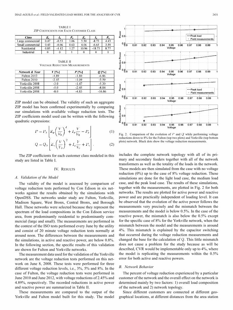
The validity of the model is assessed by comparison ofvoltage reduction tests performed by Con Edison in six net-works against the results obtained by the simulations withOpenDSS. The networks under study are Fulton, Yorkville,Madison Square, West Bronx, Central Bronx, and BoroughHall. These networks were selected because they represent thespectrum of the load compositions in the Con Edison servicearea, from predominantly residential to predominantly com-mercial (large and small). The measurements are performed inthe context of the ISO tests performed every June by the utilityand consist of 20 minute voltage reduction tests normally ataround noon. The differences between the measurements andthe simulations, in active and reactive power, are below 0.8%.In the following section, the specific results of this validationare shown for Fulton and Yorkville networks.Themeasurement data used for the validation of the Yorkville
network are the voltage reduction tests performed on this net-work on June 8, 2008. These tests were performed for threedifferent voltage reduction levels, i.e., 3%, 5% and 8%. In thecase of Fulton, the voltage reduction tests were performed inJune 2010 and June 2012, with voltage reductions of 2.45% and4.89%, respectively. The recorded reductions in active powerand reactive power are summarized in Table II.These measurements are compared to the output of the
Yorkville and Fulton model built for this study. The model
Fig. 2. Comparison of the evolution of and while performing voltagereductions down to 8% for the Fulton (top two plots) and Yorkville (top bottomplots) network. Black dots show the voltage reduction measurements.
includes the complete network topology with all of its pri-mary and secondary feeders together with all of the networktransformers as well as the totality of the loads in the network.These models are then simulated from the case with no voltagereduction (0%) up to the case of 8% voltage reduction. Thesesimulations are done for the light load case, the medium loadcase, and the peak load case. The results of these simulations,together with the measurements, are plotted in Fig. 2 for bothnetworks. The results are plotted for active power and reactivepower and are practically independent of loading level. It canbe observed that the evolution of the active power follows themeasurements very precisely and the mismatch between themeasurements and the model is below 0.5%. In the case of thereactive power, the mismatch is also below the 0.5% exceptfor the specific case of 8% for the Yorkville network, when themismatch between the model and the measurements is around4%. This mismatch is explained by the capacitor switchingthat occurred during the voltage reduction measurements andchanged the base for the calculation of . This little mismatchdoes not cause a problem for the study because as will bedescribed, CVR would be implementable only up to 4%, wherethe model is replicating the measurements within the 0.5%error for both active and reactive powers.
B. Network Behavior
The percent of voltage reduction experienced by a particularcustomer of the network and the overall effect on the network isdetermined mainly by two factors: 1) overall load compositionof the network and 2) network topology.Since different customers are connected at different geo-
graphical locations, at different distances from the area station

2432 IEEE TRANSACTIONS ON POWER DELIVERY, VOL. 28, NO. 4, OCTOBER 2013
TABLE IIINETWORK CHARACTERISTICS
(through primary feeders, network transformers and secondaryfeeders), the effect of voltage reduction experienced by the cus-tomers is not the same.The overall load of the network is a composite of the per-
cent contribution from each of the service class (i.e., residentialcustomer, small commercial and large commercial customers).In turn, the behavior of each service class - and - de-pends on the percentage of each set of appliances and equip-ment available in each type of customer. Not only does the loadcomposition contribute to the overall - and - characteris-tics of each network, but also its topology. Since the topology isdifferent for each network, the average effect on the customersvaries from network to network. The overall reduction in energyis hence both load and network dependent.In this paper, two different networks in New York City,
Fulton, and Yorkville are analyzed. These two networks areboth located in Manhattan but have very different charac-teristics as summarized in Table III. Fulton is one of thesmallest networks in Manhattan and its customers are mainlycommercial (86.73% are large commercial, 6.38% are smallcommercial, 3.06% are residential, and 3.83% are industrialcustomers). At the same time, Fulton is a network with high ro-bustness to contingency situations. On the other hand, Yorkvilleis one of the largest networks in the island of Manhattan and hasa large number of residential and small commercial customers(roughly 40%). Specifically, it has 61.21% large commercialcustomers, 16.38% are small commercial, 16.27% are residen-tial, and 6.14% are industrial customers. Every single customeris modeled individually in detail with its corresponding classZIP coefficient model. Each customer is connected to theirappropriate service point (manhole) in the secondary grid.Customer loads are not lumped or grouped in any way for thisstudy.The analysis of the network behavior is carried out for three
different load scenarios: 1) peak load (summer), 2) medium load(winter), and 3) light load (spring/fall) conditions. Power-flowsimulations are run for different voltage reduction cases, frombase case (no voltage reduction) down to an 8% reduction involtage. In Fig. 3, one can observe that for 4% reduction, theFulton network presents a demand reduction of nearly 2.52%( 0.63), whereas, in Fig. 4, the power reduction inYorkville is slightly above 2% ( 0.5). The evolution ofthe reactive power in both networks shows that for a voltage re-duction of 4%, the reactive power in the network is reduced by8% ( ). The Fulton network experiences an increaseof the current flow of under 1% (similar for the three load sce-narios), while the light load case (only) for Yorkville shows anincrease of 1.5% in current–all of these values are based on a4% voltage reduction scenario. For the peak case, in Yorkville,one can observe that the current increases by just 1%. Finally,
Fig. 3. Evolution of , , and losses while performing voltage reductionsdown to 8%, for the Fulton network.
Fig. 4. Evolution of , , and losses while performing voltage reductionsdown to 8%, for the Yorkville network.
the behavior of the total network losses (losses in primary andsecondary cables and both core losses and no-load losses innetwork transformers and area substation transformers) differsquite substantially from network to network, and even more im-portant, from peak load to light load scenarios. Specifically, inFulton, the decrease in power losses for the peak hour is only3.5%, but this improvement increases to 6% for light load situ-ations. In contrast, for Yorkville, losses for peak load are fairlyconstant (within the 1% margin) but are reduced by more than3% for light load periods–also based on a 4% voltage reduction.
C. Voltage Distribution
Another important aspect to study is the voltage distributionacross all loads in the network. These profiles are shown inFig. 5 for Fulton and Yorkville, respectively. This figure showsthe statistical distribution of the voltage level at all customerloads in per-unit values. These statistical distributions areshown for every demand level ( axis). The dark solid lineshows the average voltage level in the network. The opacityof the plot reflects the density of loads at each specific voltagelevel. The limits show the maximum voltage level and theminimum voltage level recorded in the network. In each plot,the voltage distribution is shown for base case (0% voltagereduction)–in blue (top graph)–and for 8% reduction–in pink(bottom graph). Note that the maximum voltage increasesin steps as the network load increases due to the line dropcompensation mechanism that operates the ULTCs.For a small network like Fulton, the voltage of the great ma-
jority of loads (99%) lies within 1% of the average, and this

DIAZ-AGUILÓ et al.: FIELD-VALIDATED LOAD MODEL FOR THE ANALYSIS OF CVR 2433
Fig. 5. Distribution of voltage values for different demand levels. Fulton net-work (top), Yorkville network (bottom). The graph in blue (top graph in eachfigure) shows the voltage distribution for a case with no voltage reduction (0%)and the graph in pink (bottom) shows the voltage distribution for 8% voltagereduction. The solid line shows the average voltage level and the opacity of theplot represents the density of loads at the specific voltage level.
distribution is narrower (lower standard deviation) for light loadperiods. This behavior is also observed in Yorkville but thevoltage distribution has a larger standard deviation. In this case,the majority of loads (99%) are within 2% of the average. An-other important aspect to note here is the average voltage levelfor both networks for the base case. While the Fulton networkhas an average voltage level of 1.03 p.u, Yorkville has an av-erage value of 1.01 p.u. This situation offers important oper-ative implications, since voltage violations are more likely tooccur in Yorkville when implementing CVR. This aspect willbe discussed in Section V. It is important to emphasize thatlow-voltage values are observed only at very few nodes (lessthan 1% of the loads are out of the dark area).In Fig. 6, one can observe the geographical voltage distribu-
tion in the Yorkville network, first for a case where no voltagereduction is applied (top plot), and second, for a voltage re-duction case of 8%. The plot shows that the voltage violationsare localized in a small geographical area. This means that theproblem can be solved locally, perhaps using a voltage regu-lator, distributed generation [17], [18], or a capacitor bank. Low-voltage loads are localized in the same geographical region, notonly for Fulton and Yorkville, but for the other four networksstudied as well (not presented in this paper). Local voltage-con-trol solutions to solve these isolated effects are being investi-gated and will be the subject of a sequel paper.
D. Loss Study
The evolution of the losses under CVR is critical because theyrelate directly to the efficiency of the network. Fig. 7 shows the
Fig. 6. Geographical voltage distribution in the Yorkville network. The top plotshows the voltage distribution for the base case (no voltage reduction) and thebottom plot shows the distribution for 8% voltage reduction. ©2012 by Google.
evolution of the total losses for the network for peak (dotted redline), medium (pink dashed line), and light load (blue solid line)when the voltage is reduced.Network losses are mainly made up of losses in cables and
transformer losses in cores and windings. Losses in cablesand transformer windings are proportional to the square of thecurrent, while losses in transformer cores are proportional tothe square of the voltage. As discussed in previous sections,when the voltage reduces, the current increases and thus theseries losses increase. On the other hand, the losses in trans-former cores reduce when the voltage reduces. These two typesof losses display opposite behavior with respect to voltagereduction.For peak load in Fulton, the network transformer core losses
represent 45% of the total losses and the cable losses only rep-resent 19%. On the other hand, for peak load in Yorkville, theseries losses represent 57% and the contribution of the lossesin the network transformer cores is 21%. The remaining share

2434 IEEE TRANSACTIONS ON POWER DELIVERY, VOL. 28, NO. 4, OCTOBER 2013
Fig. 7. Evolution of per-unit total losses, cable losses and transformer losseswhile performing voltage reduction down to 8%. The results are shown forFulton (top) and Yorkville (bottom) networks.
of the losses (22%) is due to the area substation transformers.During light-load periods the losses in the network transformercores represent more than 85% of the losses in both networks.In other words, for both networks, the losses for light load con-ditions reduce as the voltage is reduced. Nevertheless, for heavyload periods, the losses in the cables are more significant. ForFulton, the latter do not overtake the network transformer losses,but the total savings in losses are reduced from 6% (for 4%voltage reduction at light load) to 3.5% (for 4% voltage reduc-tion at peak load). On the other hand, in the case of Yorkville, atlight load the total losses are reduced by 3% (for 4% reductionin voltage). Nevertheless, one can see that for peak load, lossesremain constant while voltage is reduced. This is because theincrease of losses in the cables is compensated by the decreaseof transformer losses. All this can be observed in Fig. 7, wherethe basis (1.0 p.u.) corresponds to the case of full voltage (0%voltage reduction). The top three plots represent the losses forFulton and the bottom three plots refer to Yorkville. From left toright, the per-unit total losses, the per-unit losses in cables andthe per-unit losses in transformers are presented.This study shows that the behavior of losses vary from net-
work to network, because they are driven by different factorsthat are related to size of the network, load, and topology. Fultonis an exceptional network in terms of loading, since the loadingat the head of the feeders (limiting sections) at peak load is of49% of their full capacity. On the other hand, Yorkville is loadedat an average 88%. Yorkville is the most heavy-loaded networkin NYC. The average loading considering all primary sections(not only the limiting sections) in Fulton is 20%, for Yorkvilleis 50%, while the average of the other networks is 30%. Evenin the worst case scenario represented by Yorkville, since thenetwork feeders are not close to their full capacity, the losses
TABLE IVPARAMETERS REDUCTIONS FOR THE 4% VOLTAGE REDUCTION CASE. ENERGYAND LOSSES SAVINGS ARE AGGREGATED CALCULATIONS FOR THE WHOLEYEAR. ACTIVE POWER AND REACTIVE POWER DEMAND REDUCTIONS ARE
ONLY FOR THE PEAK HOUR OF THE YEAR
are constant or reduced. Therefore, it can be stated that the op-eration of the secondary distribution networks becomes moreefficient under CVR.
E. Yearly Simulations
Finally, in this section, the yearly results are presented. Theseresults are obtained by simulating 8760 cases (one case for eachhour of the year) for each of the networks taking into accountthe hourly load models presented and described in Section III.Also, these simulations are done for all voltage reduction casespresented above. The results of energy savings, network peakreduction, reactive power reduction and losses reduction foreach of the network and for the 4% voltage reduction case aresummarized in Table IV. If a 4% voltage reduction is appliedthroughout a typical year, Fulton network will save 9.6 GWhwhich represents a 2.5% energy reduction, whereas Yorkvillenetwork will save 21.54 GWh (2.33%). Peak demand and reac-tive power are also reduced substantially which would delay theinvestment for newer infrastructure. Losses are reduced morethan 500 MWh per year per network. Carbon emissions are nor-mally proportional to energy reductions; therefore, carbon emis-sions would be reduced also around 2.5% in both networks. Theresults confirm that the implementation of CVR is beneficial interms of energy savings and network efficiency.
V. VOLTAGE VIOLATIONS STUDY
The feasibility of CVR is determined by the occurrence ornot of voltage violations at each of the load points of the system.Therefore, in order to assess what the implementable CVRlevels are in each of the networks, the minimum voltage forthe peak-load hour (worst case), under normal operation–firstcontingency and second contingency–for four voltage reduc-tion cases have been computed. The ANSI standard defines114 V (95%) as the minimum service voltage and 108 V (90%)as the minimum utilization voltage [9]. In this study, we havecomputed violations for both of these levels under contingencyfor loads with a voltage base of 120 V.The results for the two networks under study are summarized
in Tables V–VII. The violations under 108 V are shown firstand the violations under 114 V are shown in parentheses. Noneof the network presents voltage violations under 108 V for the2.25% and the 4% reduction cases (only 23 nodes under 114V for 4% for Yorkville network). For the 6% case, there arestill no violations under 108 V but Yorkville presents 802 nodesunder 114 V. The minimum calculated voltages are 111.75 V(Fulton) and 108.33 V (Yorkville). In these cases, all violationsoccurred in electrically and geographically neighboring nodes.

DIAZ-AGUILÓ et al.: FIELD-VALIDATED LOAD MODEL FOR THE ANALYSIS OF CVR 2435
TABLE VNUMBER OF VOLTAGE VIOLATIONS UNDER 108 V FOR THE BASE CASE.
VIOLATIONS UNDER 114 V ARE SHOWN IN PARENTHESES
TABLE VINUMBER OF VOLTAGE VIOLATIONS UNDER 108 V FOR FIRST CONTINGENCY.
VIOLATIONS UNDER 114 V ARE SHOWN IN PARENTHESES
TABLE VIINUMBER OF VOLTAGE VIOLATIONS UNDER 108 V FOR SECOND CONTINGENCY.
VIOLATIONS UNDER 114 V ARE SHOWN IN PARENTHESES
Finally, if the analysis is extended to 8%, Fulton presents only78 nodes with violations under 114 V (minimum of 109.16 V),but Yorkville presents 17 nodes under the 108V level (minimumof 105.39 V).The same study has been performed for all first and second
contingency cases. In both cases, the minimum voltages for thepeak-load hour have also been recorded.For the first contingency analysis, all possible cases with one
feeder disconnected are simulated. Then the hour of the yearthat shows the largest number of voltage violations is selected.The results are presented in Table VI. The Fulton network ex-hibits an acceptable performance down to a voltage reduction of4% where only one node with voltage violation is found. On theother hand, the Yorkville network presents unacceptable figuresfor reductions beyond 4%, because violations are not geograph-ically close and the number of customers affected is larger than1% (1080 voltage violations).Finally, the second contingency analysis is presented in
Table VII. Analogously to the first contingency study, allnetwork configurations with two feeders disconnected aresimulated and the combination that presents the most voltageviolations is selected.In summary, it can be stated that voltage reductions down
to 4% can be implemented in most of New York City, withoutthe need of important investments in the infrastructure of thenetwork. This is possible because only a few voltage violationsare present and only occur for the peak hours of the year. Inthe second contingency case, for the peak hour, the load under108 V is only 0.21% of the total demand. Note also that theutility could decide to operate only at 2.25% voltage reductionfor these peak hours if necessary.
VI. CONCLUSION
In this paper, a complete study of conservation voltagereduction in some of the highly meshed secondary networksthat exist in New York City is undertaken. The analysis coversthe behavior of losses, voltage distribution, voltage violations,
yearly energy savings, and active/reactive power throughout theyear. This paper presents the first voltage-reduction validatedmodel with field measurements in highly meshed distributionnetworks. The results show that the implementation of CVRup to 4% is satisfactory because active and reactive powerdemands are reduced. Moreover, due to the stiffness of thehighly meshed secondary networks, direct savings are obtainedbecause there is no need for capital investments.The CVR factor for active power varies from 0.5 to 1.0 and
the CVR factor for reactive power ranges from 1.2 to 2.0. There-fore, voltage reduction in highly meshed secondary distributionnetworks is feasible and beneficial. Nevertheless, localized low-voltage violations may occur. Consequently, these situationscan be easily identified and locally solved by adding voltageregulators or distributed generators. Contingency analyses showthat reductions up to 4% could be implemented safely withoutthe need for costly infrastructure investments and attaining sig-nificant savings in energy.
REFERENCES[1] B. Scalley and D. Kasten, “The effects of distribution voltage reduction
on power and energy consumption,” IEEE Trans. Educ., vol. 24, no. 3,pp. 210–216, Aug. 1981.
[2] D. Kirshner, “Implementation of conservation voltage reduction atcommonwealth Edison,” IEEE Trans. Power Syst., vol. 5, no. 4, pp.1178–1182, May 1990.
[3] D. Lauria, “Conservation Voltage Reduction (CVR) at northeast util-ities,” IEEE Trans. Power Del., vol. PWRD-2, no. 4, pp. 1186–1191,Aug. 1987.
[4] K. P. Schneider, F. K. Tuffner, J. C. Fuller, and R. Singh, “Evaluationof conservation voltage reduction (CVR) on a national level,” PacificNorthwest National Laboratory, Richland,WA, Rep. no. PNNL-19596,Jul. 2010.
[5] K. Matar, “Impact of voltage reduction on energy and demand,”Ohio LINK Electronic Theses and Dissertations Center, College Eng.Technol., Ohio University, OH, 1990.
[6] V. Dabic, S. Cheong, J. Peralta, and D. Acebedo, “BC Hydro’s expe-rience on voltage VAR optimization in distribution system,” presentedat the IEEE Power Energy Soc. Transm. Distrib. Conf. Expo., New Or-leans, LA, 2010.
[7] V. J. Warnock and T. L. Kirkpatrick, “Impact of voltage reduction onenergy and demand: Phase II,” IEEE Trans. Power Syst., vol. PWRS-1,no. 2, pp. 92–95, May 1986.
[8] S. Lefebvre, G. Gaba, A.-O. Ba, D. Asber, A. Ricard, C. Perreault, andD. Chartrand, “Measuring the efficiency of voltage reduction at Hydro-Québec distribution,” presented at the IEEE Power Energy Soc. Gen.Meeting – Convers. Del. Elect. Energy in the 21st Century, Pittsburgh,PA, Jul. 2008.
[9] American National Standard for Electric Power Systems and Equip-ment. Voltage Ratings (60 Hertz), ANSI Standard C-84.1-2011, 2011.
[10] J. G. De Steese, S. B. Merrick, and B. W. Kennedy, “Estimatingmethodology for a large regional application of conservation voltagereduction,” IEEE Trans. Power Syst., vol. 5, no. 3, pp. 862–870, Aug.1990.
[11] T. L. Wilson, “Measurement and verifications of distribution voltageoptimization results for the IEEE Power and Energy Society,” pre-sented at the IEEE Power Energy Soc. Gen. Meeting, Minneapolis,MN, Jul. 2010.
[12] Electrical Transmission and Distribution. Reference Book, 5th ed.Pittsburgh, PA: Westinghouse Electric Corp., pp. 666–716.
[13] R. C. Dugan, “An open source platform for collaborating on smart gridresearch,” presented at the IEEE Power Energy Soc. Gen. Meeting, SanDiego, CA, Jul. 2011.
[14] “IEEE Task Force on Load Representation for Dynamic Performance.“Load representation for dynamic performance analysis (of power sys-tems)”,” IEEE Trans. Power Syst., vol. 8, no. 2, pp. 472–482, May1993.
[15] “IEEE Task Force on Load Representation for Dynamic Performance.“Standard load models for power flow and dynamic performance simu-lation”,” IEEE Trans. Power Syst., vol. 10, no. 3, pp. 1302–1313, Aug.1995.

2436 IEEE TRANSACTIONS ON POWER DELIVERY, VOL. 28, NO. 4, OCTOBER 2013
[16] A. Bokhari, A. Alkan, A. Sharma, R. Dogan, M. Diaz-Aguilo, F. deLeón, D. Czarkowski, Z. Zabar, A. Noel, and R. Uosef, “Experimentaldetermination of ZIP coefficients for Modern Residential, Commercialand Industrial Loads,” IEEE Trans. Power Del., submitted for publica-tion.
[17] L. Yu, D. Czarkowski, and F. de León, “Optimal distributed control forvoltage regulation of distribution systems with distributed generationresources,” IEEE Trans. Smart Grid, vol. 3, no. 2, pp. 959–967, Jun.2012.
[18] P. C. Chen, R. Salcedo, Q. Zhu, F. de León, D. Czarkowski, Z. P. Jiang,V. Spitsa, Z. Zabar, and R. E. Uosef, “Analysis of voltage profile prob-lems due to the penetration of distributed generation in low-voltagesecondary distribution networks,” IEEE Trans. Power Del., vol. 27,no. 4, pp. 2020–2027, Oct. 2012.
Marc Diaz Aguiló was born in Barcelona, Spain. He received the M.Sc. degreein telecommunications engineering from the Technical University of Catalonia(UPC), Barcelona, Spain, in 2006; the M.Sc. degree in aerospace controls en-gineering from a joint program between Supaero, Toulouse, France, and MIT,Cambridge, MA, in 2008; and the Ph.D. degree in aerospace simulation andcontrols from the Technical University of Catalonia, Barcelona, Spain, in 2011.Currently, he is a Postdoctoral Researcher at Polytechnic Institute of New
York University, Brooklyn, NY, USA. His research interests are in power sys-tems, controls, smart-grid implementations, and large systems modeling andsimulation.
Julien Sandraz was born in Chambéry, Savoie, France. He received the M.Sc.degree in telecommunications engineering (“diplôme d’ingénieur”) from the“Institut National des Sciences Appliquées de Lyon” (INSA Lyon), Villeur-banne, France, in 2010, the M.Sc. degree in electrical engineering from thePolytechnic Institute of New York University, Brooklyn, NY, USA, and is cur-rently pursuing the Ph.D. degree in electrical engineering with a concentrationin power systems at Polytechnic Institute of New York University, Brooklyn,NY, USA, focusing on nonlinear multiphase active and reactive power defini-tion and measurement.
Richard Macwan was born in Ahmedabad, Gujarat, India. He received theB.Eng. degree in electrical engineering from Gujarat University, Gujarat, India,in 2008 and the M.Sc. degree in electrical engineering from Polytechnic Insti-tute of New York University, Brooklyn, NY, USA, in 2012.He has served as an Assistant Manager at Essar Engineering Services Ltd.,
Mumbai, Maharashtra, India, and has experience in industrial power systemdesign and construction.
Francisco de León (S’86–M’92–SM’02) received the B.Sc. and the M.Sc.(Hons.) degrees in electrical engineering from the National PolytechnicInstitute, Mexico City, Mexico, in 1983 and 1986, respectively, and the Ph.D.degree in electrical engineering from the University of Toronto, Toronto, ON,Canada, in 1992.He has held several academic positions in Mexico and has worked for the
Canadian electric industry. Currently, he is an Associate Professor at the Poly-technic Institute of New York University, Brooklyn, NY, USA. His researchinterests include the analysis of power phenomena under nonsinusoidal con-ditions, the transient and steady-state analyses of power systems, the thermalrating of cables and transformers, and the calculation of electromagnetic fieldsapplied to machine design and modeling.
Dariusz Czarkowski (M’97) received the M.Sc. degree in electronics fromthe AGH University of Science and Technology, Cracow, Poland, in 1989, theM.Sc. degree in electrical engineering from Wright State University, Dayton,OH, in 1993, and the Ph.D. degree in electrical engineering from the Universityof Florida, Gainesville, FL, USA, in 1996.In 1996, he joined the Polytechnic Institute of New York University,
Brooklyn, NY, where he is currently an Associate Professor of Electricaland Computer Engineering. He is a coauthor of Resonant Power Converters(Wiley Interscience). He has served as an Associate Editor for the IEEETRANSACTIONS ON CIRCUITS AND SYSTEMS. His research interests are in theareas of power electronics, electric drives, and power quality.
Christopher Comack (M’07) received the B.Sc. degree in electrical engi-neering from the University of Massachusetts, Amherst, MA, USA, in 2009.In 2009, he joined Consolidated Edison Co., New York, and is currently an
Associate Engineer in the Analytics Section of the Electric DistributionNetworkSystems Department. His interests are in power system and power quality.
David Wang (S’90–M’90–SM’07) received the B.S. degree in electrical engi-neering from Shanghai University of Engineering Science, Shanghai, China, in1988, the M.S. degree in electrical engineering from New Jersey Institute ofTechnology, Newark, NJ, USA, in 1990, the M.S. degree in computer sciencefrom New York University, New York, USA, in 1998, and the Ph.D. degreein electrical engineering from Polytechnic University, Brooklyn, NY, USA, in2006.Dr. Wang joined Con Edison’s R&D Department in 1991 and currently he
is a Technical Expert in the Distribution Engineering Department responsiblefor the development of Con Edison’s distribution system design and analysissoftware.