Embed Size (px)
Citation preview
IEEE SENSORS JOURNAL, VOL. 7, NO. 12, DECEMBER 2007 1711
A Wireless Pharmaceutical Compliance MonitoringSystem Based on Magneto-Inductive Sensors
Xueliang Huo, Student Member, IEEE, and Maysam Ghovanloo, Member, IEEE
Abstract—We have developed a magnetic sensor-based wirelesspharmaceutical compliance monitoring (PCM) system using anarray of magneto-inductive sensors mounted around the patient’sneck in the form of a tight necklace. This system detects thepassage of a pill or capsule embedded with a small permanentmagnet as a tracer through the esophagus upon ingestion. As aresult, a signal representing a “dose ingestion event” is generatedand wirelessly transmitted to a data delivery device (PDA), whichis carried on the patient’s body. A software application runningon the PDA time/date stamps the event and stores it for laterretrieval by a physician. This technology provides a safe, con-venient, low-cost, and accurate detection mechanism that helpspatients adhere with their prescribed medication regimens. Italso helps researchers and pharmaceutical companies conductmore accurate clinical trials on new drugs. A proof-of-conceptprototype system using off-the-shelf components and custom PCBhas been developed and successfully tested. Preliminary resultsusing an artificial neck showed 94.4% correct detections when themagnetic tracer passed through the detection zone and about 6%false positives for outside areas.
Index Terms—Magneto-inductive sensors, permanentmagnets, pharmaceutical compliance monitoring (PCM),pharmacotherapy.
I. INTRODUCTION
PHARMACEUTICAL compliance in a medical contextrefers to a patient both agreeing to and undergoing taking
his/her regular medication as advised by his/her doctor or otherhealthcare professional [1]. Obviously, even the best drugs donot work in patients who do not take them. It is an establishedfact that over 50% of patients, especially those assigned to longterm treatments, do not comply with their medication plans bytaking them at the wrong time, stopping too early, or taking thewrong dosage [2]. Meanwhile, studies carried out in the UnitedStates and Europe reveal that noncompliance costs societiesbillions of dollars each year as a result of rehospitalization,complications, disease progressions, and even death [1]–[5].
There are many reasons why patients do not comply with acertain course of medication. They may think side-effects out-
Manuscript received April 29, 2007; revised August 19, 2007; acceptedSeptember 18, 2007. This work was supported in part by funding provided bythe Dow Chemical Company, Midland, MI. The associate editor coordinatingthe review of this paper and approving it for publication was Prof. RalphEtienne-Cummings.
The authors are with the GT-Bionics Laboratory, Department of Elec-trical and Computer Engineering, Georgia Institute of Technology, Atlanta,GA 30308 USA (e-mail: [email protected]; [email protected];[email protected]).
Color versions of one or more of the figures in this paper are available onlineat http://ieeexplore.ieee.org.
Digital Object Identifier 10.1109/JSEN.2007.909233
weigh benefits, not believe the diagnosis, not understand the di-rections correctly, not know enough about the side-effects, viewthe medicine as too costly, or they may use it too much or toolittle. The most common reason, however, is simply forgetful-ness especially among elderly patients [6].
The pharmaceutical compliance monitoring (PCM) devicescan help patients remember and their caregivers regularly tracktheir compliance regimens. Using various mechanisms, a PCMdevice can detect the dose and time that patients have taken theirmedicine and record that information. Patients will be notifiedby the device if they do not take their medicine in proper dosageand time. The doctor can also track the patients’ compliancehistory, compare it with the outcomes and possible side effects,and determine to continue, fine tune, or change the prescription.
The most critical period for PCM, however, is during clinicaltrials which determine the benefits and efficacy of new drugs. Onthe basis of the results of such trials, new medications are eitherlicensed for general use or abandoned. They also determine therecommended dosing strategies for specific clinical indications.Thus, inaccurate data during these clinical trials can result indecisions that will affect millions of patients during an approveddrug lifetime [1]. Alternatively, they can result in a potentiallyeffective drug to be abandoned.
So far, the industry standards for PCM have been pill countsreturned to the study monitor and medication diaries kept bythe patients, none of which are accurate because of their de-pendence on the patients’ active input [7]. Patients are proneto fill out diaries just before meeting the monitor or “adjust”their medication to compensate for missed doses. Thus, the topicof pharmaceutical compliance has become a key issue due toincreasing difficulties in achieving point-of-differentiation andhealth economic objectives justifying premium pricing and re-imbursement. Accurate PCM can help in shortening the newdrug approval time by reducing the number of repeated clinicaltrials due to inconclusive results, cutting the number of recruitedsubjects and duration of each trial without losing any useful in-formation, and identifying noncompliant subjects for immediatephysician intervention or exclusion from the study.
In this paper, we present a new wireless PCM technologybased on detection of permanent magnetic tracers embedded insolid medications such as pills and capsules using a body-wornarray of sensitive magneto-inductive sensors. This technology,called MagneTrace, is suitable for small- and large-scale clin-ical trials, as well as individual patients, if integrated as part ofthe marketed drug concept. The following section reviews thestate-of-the-art in the PCM technology followed by an overviewof the MagneTrace system in Section III. Sections IV and V de-scribe the prototype MagneTrace hardware and its sensor signalprocessing (SSP) algorithms, respectively. Experimental results
1530-437X/$25.00 © 2007 IEEE
1712 IEEE SENSORS JOURNAL, VOL. 7, NO. 12, DECEMBER 2007
are depicted in Section VI, followed by concluding remarks inSection VII.
II. STATE OF THE ART IN PCM
Modern PCM systems that do not entirely rely on patients’active participation can be categorized into two types with re-spect to their detection mechanism:
a) Noningestion PCM: This type of devices detects the pa-tients’ preparation action before taking the medication. Many ofthese systems act when the medication is being taken out of itspackaging or container. A typical example is SIMpill developedby Clinical Technology Advisors Inc. [8]. When the user opensthe bottle during a predefined time window, SIMpill wirelesslysends a message to a secure central computer system throughthe user’s cell phone indicating that a dose has been taken (outof the container). If the message is not received within the pro-grammed time window, an outgoing text message is sent to thepatient’s cell phone reminding him/her to take the medication.If the bottle is still not opened within 30 min, a text message in-dicating a missed dose can be sent to up to two designated care-givers’ or monitors’ cell phones. Caregivers can then contact thepatient by other means and ensure that the medication is in factconsumed. Another example is the Medic electronic compliancemonitoring package, developed by Information Mediary Corpo-ration, which has a similar concept built around the medicationblisters, taking advantage of the radio frequency identification(RFID) technology [9], [10]. In this case, taking the pill out ofits package breaks a printed conductive interconnect and initi-ates an event.
These kinds of PCM devices are safe, simple, low-cost, andeasy to operate. However, they do not really monitor the inges-tion of the medication. Therefore, they can be easily deceivedby the users either deliberately or unintentionally. These PCMsystems are not yet smart enough to indicate who has taken themedication out of the package and what has been done with themedication.
b) Ingestion PCM: The idea behind this type of device isto detect the biomedical change in patients’ body after takingthe medication. One example is the Sequella Inc. compliancemonitoring wristwatch, which is in the preclinical stage at thetime of this publication [11]. In this technology, a light-emit-ting molecule (fluorophore) is incorporated into the medicationas a tracer. When the medication is ingested, the compliancemonitor, which should be worn on by the patient on the wristduring the course of the therapy, noninvasively detects the pres-ence of the fluorophore in the bloodstream through the skin andrecords the fact that the drug is ingested. Compared with thefirst category, this device is more effective and operates morereliably. However, the potential long-term negative side-effectsof the fluorophore tracers on the human body have not yet beenwell understood. Even though many of these chemicals are con-sidered harmless in short-term applications such as in fluoro-scopic imaging, it is not yet clear whether their benefits couldoutweigh their long-term effects.
Therefore, an entirely noninvasive, unobtrusive, and inert in-gestion detection mechanism is required for an effective and ac-curate PCM system that is preferably wireless and does not in-terfere in any ways with the human body.
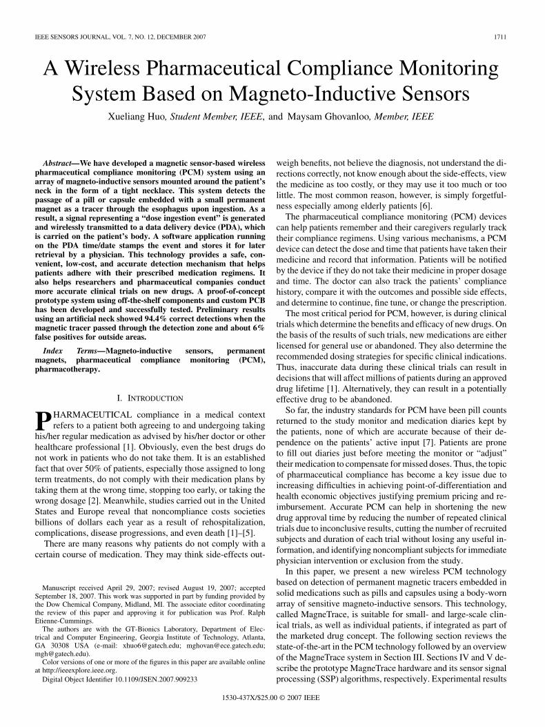
Fig. 1. (a) Schematic diagram of the wireless magnetic PCM system(MagneTrace) consisting of a magnetic tracer incorporated with the medi-cation, a detector necklace, and a data delivery device. (b) Rendered crosssection of the neck demonstrating the position of the sensor modules aroundthe esophagus, as well as the detection zone, where the proposed PCM systemlooks for the passage of the tracer.
III. SYSTEM OVERVIEW
MagneTrace is a wireless PCM system based on an array ofmagnetic field sensors placed around the user’s neck on a tightnecklace [12]. The user wears this necklace during the periodof treatment or clinical trial in order to detect the passage of asmall permanent magnetic tracer embedded in a pill or capsulethrough esophagus upon ingestion. MagneTrace system, whichsimplified block diagram and cross section are shown in Fig. 1,is composed of the following three major components.
a) Magnetic tracer: A small permanent magnet embeddedin the medication acts as a magnetic tracer. The magnet is coatedwith silicone or other inert polymer-based material, which areinsoluble in gastrointestinal (GI) tract. Since human tissue istransparent to static (DC) and low-frequency magnetic fields,the field generated by the magnetic tracer is detectable outsideof the body and can provide the magnetic sensor array with thenecessary information about the movements of the tracer as itpasses through the esophagus upon ingestion [13]. The tracer issmall enough to easily pass through the GI tract with no inter-actions and exit in about 24 hours.
b) Detection device: Consists of a wearable array of high-resolution magnetic sensor modules that are distributed on atight necklace around the user’s neck in different orientations,as shown in Fig. 1. The detection device is designed such that it
HUO AND GHOVANLOO: A WIRELESS PCM SYSTEM BASED ON MAGNETO-INDUCTIVE SENSORS 1713
can detect the tracer regardless of its orientation when it passesthrough the patient’s esophagus. The sensors are driven by acontrol unit on the same necklace that consists of a power source(battery), power management circuitry, a low-power microcon-troller (M/C), and an RF wireless transceiver. The SSP rou-tine that runs on the M/C continuously scans the sensor mod-ules and processes their outputs looking for a “dose ingestionevent” (DIE). Upon detection of a DIE, the control unit wire-lessly transmits the event to the data delivery device.
c) Data delivery device: We have taken advantage ofthe commercially available portable computing technology inchoosing the data delivery device, which can eventually be apersonal digital assistant (PDA) with built-in RF transceiver.The data delivery device is worn by the user on his/her beltor placed in a nearby location ( 30 m indoors) while beingat home or in the shower. Upon reception of a DIE, the datadelivery device sends an acknowledgment (ACK) signal backto the detector and time/date stamps the event. All the receivedevents are stored in the PDA for later retrieval by a physicianor clinical trial staff either directly from the PDA or over theinternet through a wireless local area network.
The MagneTrace PCM system is noninvasive, inherentlywireless (permanent magnet), and low-cost. The tracer, detectornecklace, and PDA have no chemical effect on the patient’sbody and are unobtrusive due to their small size and lightweight. The magnetic tracers are safe and harmless as long asthe magnet is not too strong. Multiple strong magnets in the GItract can potentially result in a blockage [14]. As a result, themagneto-inductive sensors should be sensitive enough to detectthe changes in the magnetic field resulted from small and soweak magnetic tracers. These fields, however, 5 7 cm fromtheir source, are comparable to the earth magnetic field (EMF)and its variations when the user moves around. Therefore, thearrangement of the MagneTrace sensor array on the detectornecklace and its SSP algorithm, running on the M/C, are de-signed to be able to discriminate between the magnetic fieldvariations resulted from ingestion of the tracer (DIE) and othersources of electromagnetic interference (EMI).
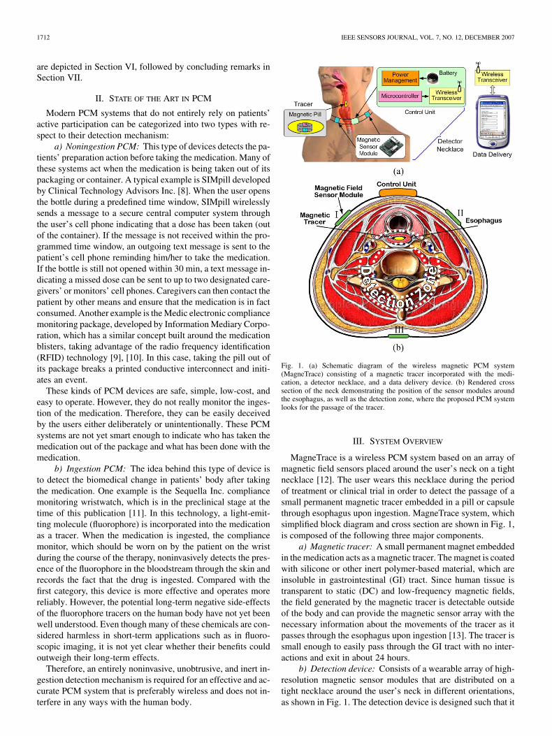
Since the magnetic force between a pair of permanentmagnets sharply decays with increasing their relative distance(see Fig. 2), another solution to reduce the risk of GI blockagewithout weakening the tracer magnetic strength is to alwaysmaintain a minimum distance between a pair of tracers. This ispossible by properly designing the thickness of the tracer inertpolymer coating or encapsulation especially over the two polesof the magnet depending on the size and magnetic strength ofthe tracer.
It is also important to differentiate between specific patternsof magnetic field variations that result from genuine passageof a tracer through the esophagus and those resulted from, forexample, waving a pill near the detector necklace or even falselypassing it between the user’s neck and the necklace. This wouldeliminate any intentional or inadvertent errors and add to theaccuracy of the MagneTrace system. Using the same hardwaredescribed in this paper, while utilizing a more sophisticated SSPalgorithm, it is also possible to sensitize the MagneTrace systemto two or more types of tracers with different magnetic strengthsin order to detect and monitor two or more medications that
Fig. 2. (a) Experimentally measured and calculated on-axis normalized PNImagnetic field sensor output and magnetic field strength based on parameters inTable I substituted in (1). (b) Relative size of different permanent magnets thatgenerate similar magnetic field strength at a certain distance [15].
are consumed together. Nevertheless, the algorithm presentedin Section IV is designed to detect only one type of tracer at thispoint.
IV. MAGNETRACE PROTOTYPE HARDWARE
In order to evaluate the feasibility and performance of the pro-posed approach for PCM, we have developed a proof-of-con-cept wireless magnetic PCM prototype using only off-the-shelfcomponents. The main hardware components of the prototypeMagneTrace system are described in the following.
A. Permanent Magnetic Tracer
The key parameters used to describe characteristics of a per-manent magnet are the residual induction , coercive force
, and peak energy density . is a measure ofthe residual magnetic strength of a permanent magnet after theexternal magnetization field is removed. Therefore, it is directlyproportional to the field generated by the permanent magnet. Fora cylindrical magnet, shown in Fig. 2(a), the on-axis magneticfield strength in Gauss at distance from a pole of the magnetalso depends on its size and can be calculated from
(1)
where is the length and is the diameter of the magnet, allin cm. In order to minimize the size of the tracer, should bemaximized. Fig. 2(b), which shows the relative size of the mostpopular permanent magnets to generate the same output, clearlyindicates that NdFeB, also known as rare earth magnet is thematerial of choice [15]. Table I summarizes the specificationsof the rare earth magnet from RadioShack (Forth Worth, TX),which we used in our experiments [16]. It should be noted thatthe MagneTrace SSP algorithms can be calibrated to any tracerregardless of its , size, and shape, which could eventually besmaller and weaker than the one we used.
B. Detection Device
High sensitivity, low-power consumption, and small size arethe key aspects in design of the detection device, which af-fect the PCM efficacy and user comfort. Currently, the mostpopular commercially available magnetic field sensors are the
1714 IEEE SENSORS JOURNAL, VOL. 7, NO. 12, DECEMBER 2007
TABLE IPROTOTYPE MEGNETRACE SYSTEM SPECIFICATIONS
Hall-effect, fluxgate, magneto-resistive, and magneto- inductivesensors [17]–[20]. Hall-effect sensors are the smallest solution,while magneto-resistive and fluxgate sensors offer the highestsensitivity. However, when power consumption, interface cir-cuitry, size, cost, and commercial availability were consideredtogether, magneto-inductive sensors turned out to be the bestchoice for this application. Magneto-inductive sensors consistof an inductive-capacitive oscillator, which output frequencychanges with the magnetic flux density passing through the coreof the sensor coil in parallel to its axis.
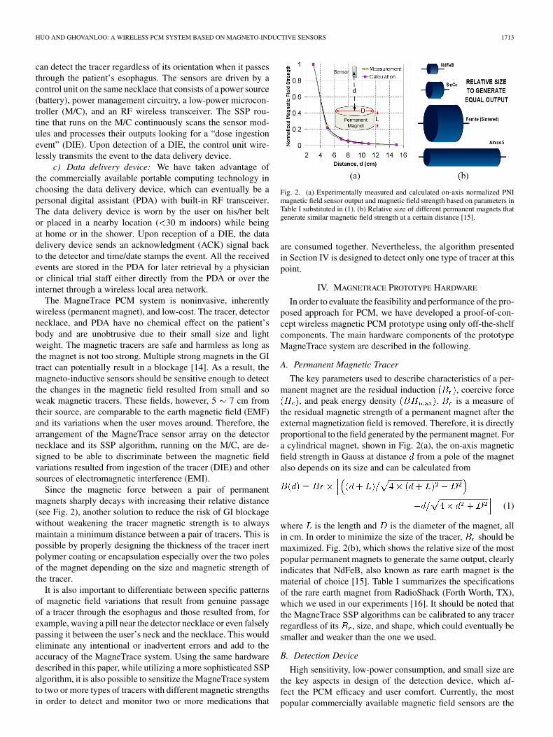
Fig. 3(a) inset shows a MicroMag2 sensor module from PNI(Santa Rosa, CA), which is used in the present MagneTrace pro-totype [19]. Each module, which specifications are summarizedin Table I, incorporates two sensors with perpendicular axes in
and directions. Fig. 3(b) shows one of these sensors ona U.S. penny. In these magneto-inductive sensors, the induc-tance can change by 100% over the designated range of mag-netic field measurement. The MicroMag2 module also includesa sensor interface chip with oscillator and counter circuits thatare temperature stabilized and provide a programmable sensi-tivity over a wide range. The chip also includes a bidirectionalserial peripheral interface (SPI) bus that can directly send dig-itized measured magnetic field samples to the control unit andreceive control commands.
It takes about 1–3 s for the pill to pass through the esoph-agus upon ingestion and that is the only time when the tracer isin the vicinity of the detector device. Therefore, the samplingrate must be selected sufficiently high to provide enough infor-mation for the SSP algorithm to effectively detect the DIE. Onthe other hand, higher sampling rates increase the overall powerconsumption and there is an inverse relationship between the
Fig. 3. (a) PNI MicroMag2 two-axis sensor module. (b) A PNI magneto-in-ductive sensor on a U.S. penny. (c) Prototype MagneTrace detector necklaceconsisting of three MicroMag2 sensor modules and a control unit. (d) Samplewaveforms recorded at 11 samples/s from threeX axis and threeZ axis sensorswhile passing a magnetic tracer through the artificial neck, resembling ingestion(DIE). Sensor counts are proportional to the measured magnetic field strength[19].
sampling rate and the resolution of the digitized sensor out-puts. In other words, higher resolution samples require moretime to be taken. Therefore, there should be a compromise be-tween sensitivity, sampling rate, and power consumption of thedetector device. A sampling rate of about 10 Hz was experimen-tally found to be sufficient for the SSP.
In the prototype detection device, three MicroMag2 sensormodules are mounted on a flat ribbon cable to form a necklaceand capture the magnetic field variations around the user’s neck,as shown in Fig. 3(c). The modules are equally distanced onthe flat cable which forms a shared bus between modules andthe control unit, while encompassing the user’s neck and con-necting to the control unit from both sides. If the necklace formsa perfect circle around the neck, as shown in Fig. 1(b), the three
HUO AND GHOVANLOO: A WIRELESS PCM SYSTEM BASED ON MAGNETO-INDUCTIVE SENSORS 1715
TABLE IIPOWER CONSUMPTION OF THE MAGNETIC DCM SYSTEM
horizontal sensor axes make an equilateral triangle and thethree vertical sensors axes will be in parallel to the tracer pathalong the esophagus. Nonetheless, the SSP algorithm does notnecessitate the necklace to form a perfect circle. Fig. 3(d) showssample sensor outputs while passing a tracer through an artifi-cial neck, resembling ingestion (see Fig. 5).
A low-power M/C, Atmega32L [21], is the heart of the con-trol unit, which scans the three sensor modules turning onlyone of them on at a time to save power. All measurement re-sults are processed within this M/C to detect a DIE. The M/Calso controls a low-power commercial RF transceiver (LAIPAC,Canada) operating at 2.4 GHz [22], [23]. The transceiver is firstconfigured as a transmitter to transmit the DIE to the data de-livery device and then switches to receive mode to detect theACK signal. In the absence of an ACK after four transmissions,the control unit notifies the user by turning on a red LED.
Table II summarizes the power consumption of differentblocks on the detector necklace at 3.3 V. The wireless trans-ceiver is the most power consuming block on the detector.However, since the DIE is only triggered a few times per day,the detector operates at a low-power monitoring mode exceptfor a total of 1 or 2 s. The operating time of the detectornecklace is highly dependent on the size and capacity of thebattery used. The current prototype is expected to operate for3–5 days with two 600 mAh Zinc Air hearing aid batteriesor 9–12 days with two 1800 mAh AAA batteries [24]. Usingultra low-power microcontrollers such as MSP430 (TexasInstruments, Dallas, TX) and employing more efficient powermanagement routines, it is possible to significantly reduce theoverall system power consumption and enhance its operatingtime. Eventually, a custom designed integrated control unit canextend the operating time up to several weeks, preferably fromone doctor’s visit to the next.
C. Data Delivery Device
A similar control unit with RF transceiver is used on the datadelivery side in this prototype version. It captures the DIE mes-sage transmitted by the detection device and communicates itthrough an RS-232 port to a PC, which runs the PCM graph-ical user interface (GUI) in LabVIEW environment. The GUI,shown in Fig. 5(a), time and date stamps the event and saves itin a spreadsheet file, while showing the ten most recent events.The GUI also includes a calibration and adjustment menu, onlyaccessible to the doctor or professional staff in the final version,through which all the SSP threshold parameters can be wire-lessly updated on the detection device. Future versions of theGUI will also include entries for prescription schedules to befilled by the doctors in order to remind the patients to take their
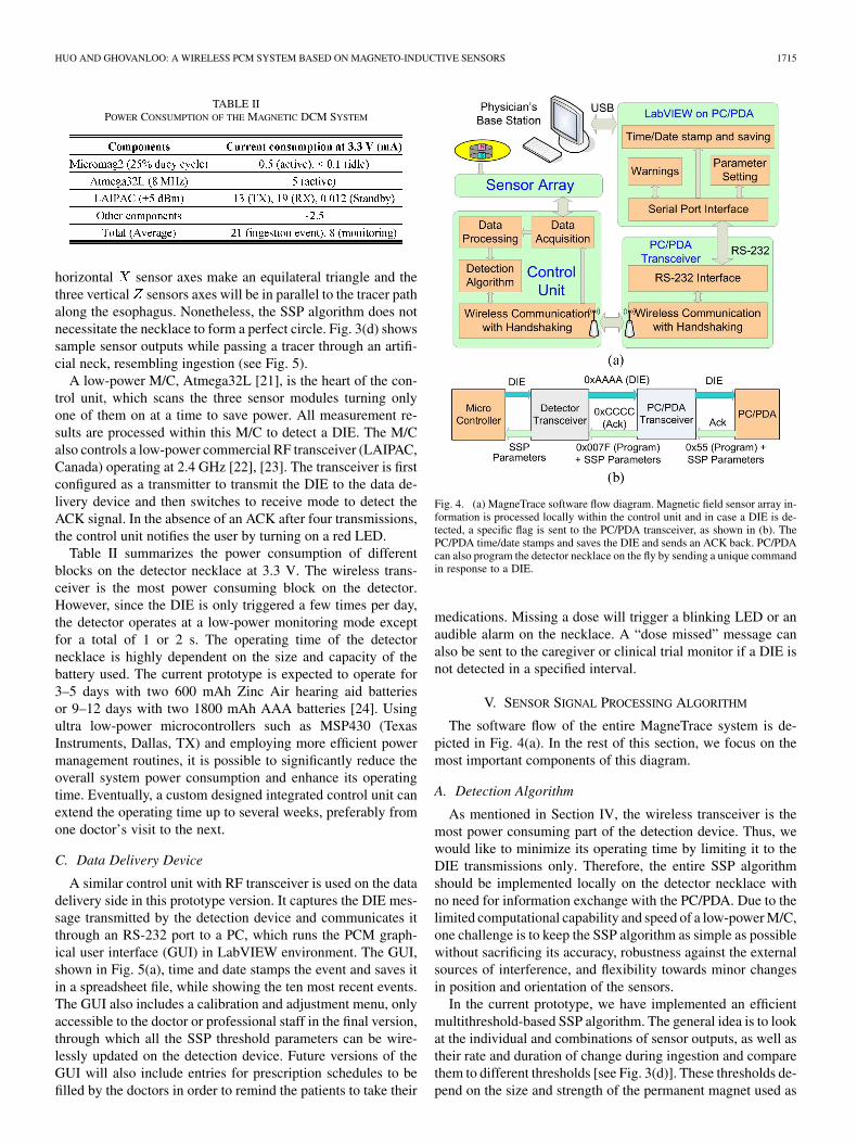
Fig. 4. (a) MagneTrace software flow diagram. Magnetic field sensor array in-formation is processed locally within the control unit and in case a DIE is de-tected, a specific flag is sent to the PC/PDA transceiver, as shown in (b). ThePC/PDA time/date stamps and saves the DIE and sends an ACK back. PC/PDAcan also program the detector necklace on the fly by sending a unique commandin response to a DIE.
medications. Missing a dose will trigger a blinking LED or anaudible alarm on the necklace. A “dose missed” message canalso be sent to the caregiver or clinical trial monitor if a DIE isnot detected in a specified interval.
V. SENSOR SIGNAL PROCESSING ALGORITHM
The software flow of the entire MagneTrace system is de-picted in Fig. 4(a). In the rest of this section, we focus on themost important components of this diagram.
A. Detection Algorithm
As mentioned in Section IV, the wireless transceiver is themost power consuming part of the detection device. Thus, wewould like to minimize its operating time by limiting it to theDIE transmissions only. Therefore, the entire SSP algorithmshould be implemented locally on the detector necklace withno need for information exchange with the PC/PDA. Due to thelimited computational capability and speed of a low-power M/C,one challenge is to keep the SSP algorithm as simple as possiblewithout sacrificing its accuracy, robustness against the externalsources of interference, and flexibility towards minor changesin position and orientation of the sensors.
In the current prototype, we have implemented an efficientmultithreshold-based SSP algorithm. The general idea is to lookat the individual and combinations of sensor outputs, as well astheir rate and duration of change during ingestion and comparethem to different thresholds [see Fig. 3(d)]. These thresholds de-pend on the size and strength of the permanent magnet used as
1716 IEEE SENSORS JOURNAL, VOL. 7, NO. 12, DECEMBER 2007
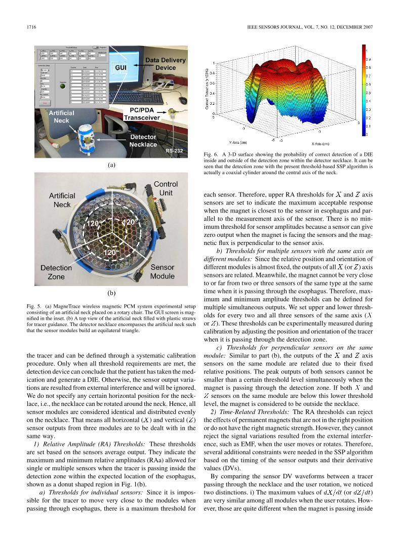
Fig. 5. (a) MagneTrace wireless magnetic PCM system experimental setupconsisting of an artificial neck placed on a rotary chair. The GUI screen is mag-nified in the inset. (b) A top view of the artificial neck filled with plastic strawsfor tracer guidance. The detector necklace encompasses the artificial neck suchthat the sensor modules build an equilateral triangle.
the tracer and can be defined through a systematic calibrationprocedure. Only when all threshold requirements are met, thedetection device can conclude that the patient has taken the med-ication and generate a DIE. Otherwise, the sensor output varia-tions are resulted from external interference and will be ignored.We do not specify any certain horizontal position for the neck-lace, i.e., the necklace can be rotated around the neck. Hence, allsensor modules are considered identical and distributed evenlyon the necklace. That means all horizontal ( ) and vertical ( )sensor outputs from three modules are to be dealt with in thesame way.
1) Relative Amplitude (RA) Thresholds: These thresholdsare set based on the sensors average output. They indicate themaximum and minimum relative amplitudes (RAa) allowed forsingle or multiple sensors when the tracer is passing inside thedetection zone within the expected location of the esophagus,shown as a donut shaped region in Fig. 1(b).
a) Thresholds for individual sensors: Since it is impos-sible for the tracer to move very close to the modules whenpassing through esophagus, there is a maximum threshold for
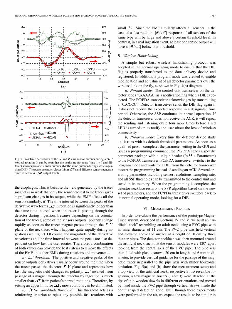
Fig. 6. A 3-D surface showing the probability of correct detection of a DIEinside and outside of the detection zone within the detector necklace. It can beseen that the detection zone with the present threshold-based SSP algorithm isactually a coaxial cylinder around the central axis of the neck.
each sensor. Therefore, upper RA thresholds for and axissensors are set to indicate the maximum acceptable responsewhen the magnet is closest to the sensor in esophagus and par-allel to the measurement axis of the sensor. There is no min-imum threshold for sensor amplitudes because a sensor can givezero output when the magnet is facing the sensors and the mag-netic flux is perpendicular to the sensor axis.
b) Thresholds for multiple sensors with the same axis ondifferent modules: Since the relative position and orientation ofdifferent modules is almost fixed, the outputs of all (or ) axissensors are related. Meanwhile, the magnet cannot be very closeto or far from two or three sensors of the same type at the sametime when it is passing through the esophagus. Therefore, max-imum and minimum amplitude thresholds can be defined formultiple simultaneous outputs. We set upper and lower thresh-olds for every two and all three sensors of the same axis (or ). These thresholds can be experimentally measured duringcalibration by adjusting the position and orientation of the tracerwhen it is passing through the detection zone.
c) Thresholds for perpendicular sensors on the samemodule: Similar to part (b), the outputs of the and axissensors on the same module are related due to their fixedrelative positions. The peak outputs of both sensors cannot besmaller than a certain threshold level simultaneously when themagnet is passing through the detection zone. If both and
sensors on the same module are below this lower thresholdlevel, the magnet is considered to be outside the necklace.
2) Time-Related Thresholds: The RA thresholds can rejectthe effects of permanent magnets that are not in the right positionor do not have the right magnetic strength. However, they cannotreject the signal variations resulted from the external interfer-ence, such as EMF, when the user moves or rotates. Therefore,several additional constraints were needed in the SSP algorithmbased on the timing of the sensor outputs and their derivativevalues (DVs).
By comparing the sensor DV waveforms between a tracerpassing through the necklace and the user rotation, we noticedtwo distinctions. i) The maximum values of (or )are very similar among all modules when the user rotates. How-ever, those are quite different when the magnet is passing inside
HUO AND GHOVANLOO: A WIRELESS PCM SYSTEM BASED ON MAGNETO-INDUCTIVE SENSORS 1717
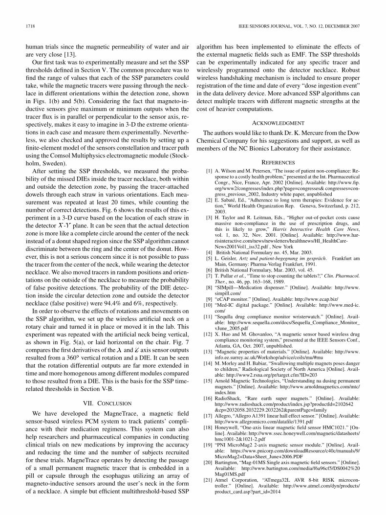
Fig. 7. (a) Time derivatives of the X and Z axis sensor outputs during a 360vertical rotation. It can be seen that the peaks are far apart (long �T ) and dif-ferent sensors provide similar outputs. (b) The same outputs during a dose inges-tion (DIE). The peaks are much closer (short�T ) and different sensors generatequite different dV=dt output levels.
the esophagus. This is because the field generated by the tracermagnet is so weak that only the sensor closest to the tracer givessignificant changes in its output, while the EMF affects all thesensors similarly. ii) The time interval between the peaks of thederivative waveforms in rotation is significantly longer thanthe same time interval when the tracer is passing through thedetector during ingestion. Because depending on the orienta-tion of the tracer, some of the sensors outputs’ polarity changerapidly as soon as the tracer magnet passes through the -plane of the necklace, which happens quite rapidly during in-gestion (see Fig. 7). Of course, the magnitude of the derivativewaveforms and the time interval between the peaks are also de-pendant on how fast the user rotates. Therefore, a combinationof both values can provide the best criteria to remove the effectsof the EMF and other EMIs during rotations and movements.
a) threshold: The positive and negative peaks of thesensor outputs derivatives usually occur around the time whenthe tracer passes the detector - plane and represents howfast the magnetic field changes its polarity. resulted frompassage of a magnet through the detector by ingestion is muchsmaller than from patient’s normal rotations. Therefore, bysetting an upper limit for , most rotations can be eliminated.
b) amplitude threshold: This threshold acts as areinforcing criterion to reject any possible fast rotations with
small . Since the EMF similarly affects all sensors, in thecase of a fast rotation, response of all sensors of thesame type will be large and above a certain threshold level. Incontrast, in a real ingestion event, at least one sensor output willhave a below that threshold.
B. Wireless Handshaking
A simple but robust wireless handshaking protocol wasadopted in the normal operating mode to ensure that the DIEflag is properly transferred to the data delivery device andregistered. In addition, a program mode was created to enablemodification and adjustment of all detector parameters over thewireless link on the fly, as shown in Fig. 4(b) diagram.
a) Normal mode: The control unit transceiver on the de-tector sends “0xAAAA” as a notification flag when a DIE is de-tected. The PC/PDA transceiver acknowledges by transmittinga “0xCCCC.” Detector transceiver sends the DIE flag again ifit does not receive the expected response in a designated timeperiod. Otherwise, the SSP continues its normal operation. Ifthe detector transceiver does not receive the ACK, it will repeatthe sending and listening cycle four more times before a redLED is turned on to notify the user about the loss of wirelessconnectivity.
b) Program mode: Every time the detector device startsup, it runs with its default threshold parameters. As soon as aqualified person completes the parameter setting in the GUI andissues a programming command, the PC/PDA sends a specificparameter package with a unique header (0x55 + Parameters)to the PC/PDA transceiver. PC/PDA transceiver switches to theprogram mode and waits for a DIE from the detector transceiverto start the programming instead of sending an ACK. Several op-erating parameters including sensor resolutions, sampling rate,and all SSP thresholds can be transmitted to the control unit andsaved in its memory. When the programming is complete, thedetector necklace restarts the SSP algorithm based on the newset of parameters, and the PC/PDA transceiver switches back toits normal operating mode, looking for a DIE.
VI. MEASUREMENT RESULTS
In order to evaluate the performance of the prototype Magne-Trace system, described in Sections IV and V, we built an “ar-tificial neck” resembling an adult neck using a PVC pipe withan inner diameter of 11 cm. The PVC pipe was held verticaland elevated above the surface at a height of 10 cm by threethinner pipes. The detector necklace was then mounted aroundthe artificial neck such that the sensor modules were 120 apartlooking from the central axis of the PVC pipe. The pipe wasthen filled with plastic straws, 20 cm in length and 6 mm in di-ameter, to provide vertical guidance for the passage of the mag-netic tracer in parallel to the pipe axis with minor horizontaldeviation. Fig. 5(a) and (b) show the measurement setup anda top view of the artificial neck, respectively. To resemble in-gestion, a few magnetic tracers (Table I) were attached at thetips of thin wooden dowels in different orientations and movedby hand inside the PVC pipe through vertical straws inside thedonut shaped detection zone. Even though these experimentswere performed in the air, we expect the results to be similar in
1718 IEEE SENSORS JOURNAL, VOL. 7, NO. 12, DECEMBER 2007
human trials since the magnetic permeability of water and airare very close [13].
Our first task was to experimentally measure and set the SSPthresholds defined in Section V. The common procedure was tofind the range of values that each of the SSP parameters couldtake, while the magnetic tracers were passing through the neck-lace in different orientations within the detection zone, shownin Figs. 1(b) and 5(b). Considering the fact that magneto-in-ductive sensors give maximum or minimum outputs when thetracer flux is in parallel or perpendicular to the sensor axis, re-spectively, makes it easy to imagine in 3-D the extreme orienta-tions in each case and measure them experimentally. Neverthe-less, we also checked and approved the results by setting up afinite-element model of the sensors constellation and tracer pathusing the Comsol Multiphysics electromagnetic module (Stock-holm, Sweden).
After setting the SSP thresholds, we measured the proba-bility of the missed DIEs inside the tracer necklace, both withinand outside the detection zone, by passing the tracer-attacheddowels through each straw in various orientations. Each mea-surement was repeated at least 20 times, while counting thenumber of correct detections. Fig. 6 shows the results of this ex-periment in a 3-D curve based on the location of each straw inthe detector - plane. It can be seen that the actual detectionzone is more like a complete circle around the center of the neckinstead of a donut shaped region since the SSP algorithm cannotdiscriminate between the ring and the center of the donut. How-ever, this is not a serious concern since it is not possible to passthe tracer from the center of the neck, while wearing the detectornecklace. We also moved tracers in random positions and orien-tations on the outside of the necklace to measure the probabilityof false positive detections. The probability of the DIE detec-tion inside the circular detection zone and outside the detectornecklace (false positive) were 94.4% and 6%, respectively.
In order to observe the effects of rotations and movements onthe SSP algorithm, we set up the wireless artificial neck on arotary chair and turned it in place or moved it in the lab. Thisexperiment was repeated with the artificial neck being vertical,as shown in Fig. 5(a), or laid horizontal on the chair. Fig. 7compares the first derivatives of the and axis sensor outputsresulted from a 360 vertical rotation and a DIE. It can be seenthat the rotation differential outputs are far more extended intime and more homogenous among different modules comparedto those resulted from a DIE. This is the basis for the SSP time-related thresholds in Section V-B.
VII. CONCLUSION
We have developed the MagneTrace, a magnetic fieldsensor-based wireless PCM system to track patients’ compli-ance with their medication regimens. This system can alsohelp researchers and pharmaceutical companies in conductingclinical trials on new medications by improving the accuracyand reducing the time and the number of subjects recruitedfor these trials. MagneTrace operates by detecting the passageof a small permanent magnetic tracer that is embedded in apill or capsule through the esophagus utilizing an array ofmagneto-inductive sensors around the user’s neck in the formof a necklace. A simple but efficient multithreshold-based SSP
algorithm has been implemented to eliminate the effects ofthe external magnetic fields such as EMF. The SSP thresholdscan be experimentally indicated for any specific tracer andwirelessly programmed onto the detector necklace. Robustwireless handshaking mechanism is included to ensure properregistration of the time and date of every “dose ingestion event”in the data delivery device. More advanced SSP algorithms candetect multiple tracers with different magnetic strengths at thecost of heavier computations.
ACKNOWLEDGMENT
The authors would like to thank Dr. K. Mercure from the DowChemical Company for his suggestions and support, as well asmembers of the NC Bionics Laboratory for their assistance.
REFERENCES
[1] A. Wilson and M. Petersen, “The issue of patient non-compliance: Re-sponse to a costly health problem,” presented at the Int. PharmaceuticalCongr., Nice, France, Apr. 2002 [Online]. Available: http://www.fip.org/www2/congresses/index.php?page=congresses& congresses=con-gress_previous_2002, Industry white paper, unpublished
[2] E. Sabaté, Ed., “Adherence to long term therapies: Evidence for ac-tion,” World Health Organization Rep. Geneva, Switzerland, p. 212,2003.
[3] H. Taylor and R. Leitman, Eds., “Higher out-of-pocket costs causemassive non-compliance in the use of prescription drugs, andthis is likely to grow,” Harris Interactive Health Care News,vol. 1, no. 32, Nov. 2001. [Online]. Available: http://www.har-risinteractive.com/news/newsletters/healthnews/HI_HealthCare-News2001Vol1_iss32.pdf , New York
[4] British National Formulary no. 45, Mar. 2003.[5] L. Geisler, Artz und patient-begegnung im gespräch. Frankfurt am
Main, Germany: Pharma-Verlag Frankfurt, 1991.[6] British National Formulary, Mar. 2003, vol. 45.[7] T. Pullar et al., “Time to stop counting the tablets?,” Clin. Pharmacol.
Ther., no. 46, pp. 163–168, 1989.[8] “SIMpill—Medication dispenser.” [Online]. Available: http://www.
simpill.com/[9] “eCAP monitor.” [Online]. Available: http://www.ecap.biz/
[10] “Med-IC digital package.” [Online]. Available: http://www.med-ic.com/
[11] “Sequlla drug compliance monitor wristerwatch.” [Online]. Avail-able: http://www.sequella.com/docs/Sequella_Compliance_Monitor_vJune_2005.pdf
[12] X. Huo and M. Ghovanloo, “A magnetic sensor based wireless drugcompliance monitoring system,” presented at the IEEE Sensors Conf.,Atlanta, GA, Oct. 2007, unpublished.
[13] “Magnetic properties of materials.” [Online]. Available: http://www.info.ee.surrey.ac.uk/Workshop/advice/coils/mu/#mu
[14] M. Morley and H. Babiar, “Swallowing multiple magnets poses dangerto children,” Radiological Society of North America [Online]. Avail-able: http://www2.rsna.org/pr/target.cfm?ID=203
[15] Arnold Magnetic Technologies, “Understanding na dusing permanentmagnets.” [Online]. Available: http://www.arnoldmagnetics.com/mtc/index.htm
[16] RadioShack, “Rare earth super magnets.” [Online]. Available:http://www.radioshack.com/product/index.jsp?productId=2102642&cp=2032058.2032229.2032262&parentPage=family
[17] Allegro, “Allegro A1391 linear hall effect sensor.” [Online]. Available:http://www.allegromicro.com/datafile/1391.pdf
[18] Honeywell, “One-axis linear magnetic field sensor HMC1021.” [On-line]. Available: http://www.ssec.honeywell.com/magnetic/datasheets/hmc1001-2&1021-2.pdf
[19] “PNI MicroMag2 2-axis magnetic sensor module.” [Online]. Avail-able: https://www.pnicorp.com/downloadResource/c40c/manuals/9/MicroMag2+Data+Sheet_June+2006.PDF
[20] Bartington, “Mag-01MS Single axis magnetic field sensors.” [Online].Available: http://www.bartington.com/media/f6a96cf5/DS0042%20Mag01MS.pdf
[21] Atmel Corporation, “ATmega32L AVR 8-bit RISK microcon-troller.” [Online]. Available: http://www.atmel.com/dyn/products/product_card.asp?part_id=2014
HUO AND GHOVANLOO: A WIRELESS PCM SYSTEM BASED ON MAGNETO-INDUCTIVE SENSORS 1719
[22] “2.4 Ghz. TRF LAIPAC transceiver.” [Online]. Available: http://www.laipac.com/easy_trf24_eng.htm
[23] Nordic Semiconductor, “nRF2401 single chip 2.4 GHz trans-ceiver.” [Online]. Available: http://www.sparkfun.com/datasheets/RF/nRF2401rev1_1.pdf
[24] Duracell, “Zinc air battery.” [Online]. Available: http://www.duracell.com/oem/Pdf/new/ZA675_Dur.pdf
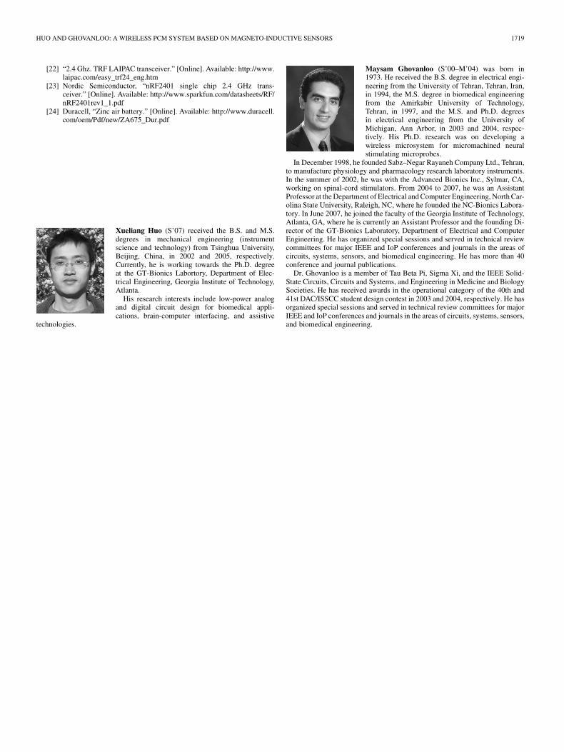
Xueliang Huo (S’07) received the B.S. and M.S.degrees in mechanical engineering (instrumentscience and technology) from Tsinghua University,Beijing, China, in 2002 and 2005, respectively.Currently, he is working towards the Ph.D. degreeat the GT-Bionics Labortory, Department of Elec-trical Engineering, Georgia Institute of Technology,Atlanta.
His research interests include low-power analogand digital circuit design for biomedical appli-cations, brain-computer interfacing, and assistive
technologies.
Maysam Ghovanloo (S’00–M’04) was born in1973. He received the B.S. degree in electrical engi-neering from the University of Tehran, Tehran, Iran,in 1994, the M.S. degree in biomedical engineeringfrom the Amirkabir University of Technology,Tehran, in 1997, and the M.S. and Ph.D. degreesin electrical engineering from the University ofMichigan, Ann Arbor, in 2003 and 2004, respec-tively. His Ph.D. research was on developing awireless microsystem for micromachined neuralstimulating microprobes.
In December 1998, he founded Sabz–Negar Rayaneh Company Ltd., Tehran,to manufacture physiology and pharmacology research laboratory instruments.In the summer of 2002, he was with the Advanced Bionics Inc., Sylmar, CA,working on spinal-cord stimulators. From 2004 to 2007, he was an AssistantProfessor at the Department of Electrical and Computer Engineering, North Car-olina State University, Raleigh, NC, where he founded the NC-Bionics Labora-tory. In June 2007, he joined the faculty of the Georgia Institute of Technology,Atlanta, GA, where he is currently an Assistant Professor and the founding Di-rector of the GT-Bionics Laboratory, Department of Electrical and ComputerEngineering. He has organized special sessions and served in technical reviewcommittees for major IEEE and IoP conferences and journals in the areas ofcircuits, systems, sensors, and biomedical engineering. He has more than 40conference and journal publications.
Dr. Ghovanloo is a member of Tau Beta Pi, Sigma Xi, and the IEEE Solid-State Circuits, Circuits and Systems, and Engineering in Medicine and BiologySocieties. He has received awards in the operational category of the 40th and41st DAC/ISSCC student design contest in 2003 and 2004, respectively. He hasorganized special sessions and served in technical review committees for majorIEEE and IoP conferences and journals in the areas of circuits, systems, sensors,and biomedical engineering.