Embed Size (px)
Citation preview
IEEE SENSORS JOURNAL, VOL. 17, NO. 23, DECEMBER 1, 2017 7723
Smart Sensors and Standard-BasedInteroperability in Smart Grids
Eugene Y. Song, Member, IEEE, Gerald J. FitzPatrick, Member, IEEE, and Kang B. Lee, Life Fellow, IEEE
Abstract— Smart grids (SGs) are electrical power grids thatapply information, advanced networking, and real-time mon-itoring and control technologies to lower costs, save energy,and improve security, interoperability, and reliability. Smartsensors (SSs) can provide real-time data and status of thegrids for real-time monitoring, protection, and control of gridoperations. Sensor data exchange and interoperability are majorchallenges for the SGs. This paper describes sensing, timing,intelligence, and communication requirements of sensors forthe SGs and proposes a general model of the SSs for SGsbased on these requirements. Then it illustrates, how the modelworks with phasor measurement unit (PMU)- and merging unit-based SSs deployed in the SGs with standardized interfaces tosupport the interoperability of the SSs. Furthermore, to addressthe interoperability issues, this paper describes sensor interfacestandards used in the SGs and the need for interoperabilitytesting, and proposes a passive interoperability test methodfor the SSs to achieve and assure sensor data interoperability.To verify this test method, an interoperability test system for thePMU-based SSs was developed and presented. Interoperabilitytest results of eight commercial PMU-based SSs are provided toshow that the proposed interoperability test method works.
Index Terms— Interface standards, interoperability test,phasor measurement unit (PMU), merging unit (MU), smartgrid (SG), smart sensor (SS).
I. INTRODUCTION
SMART grids (SGs) are electrical power grids thatapply information, advanced networking, and real-time
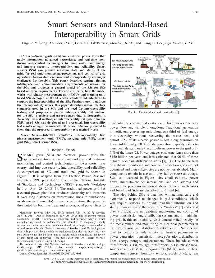
monitoring, and control technologies to lower costs, saveenergy, and improve security, interoperability, and reliability.A comparison of SG and traditional grid is shown inFigure 1. It is adapted from the Electric Power ResearchInstitute (EPRI) presentation given at the National Instituteof Standards and Technology (NIST) Standards Workshopheld on April 28, 2008 [1]. The traditional power grid hasa central power plant that produces electricity and transmitsit over long distances on transmission lines to substations,as shown in Figure 1(a). From the substation, the power isdistributed by both overhead and underground power lines to
Manuscript received May 31, 2017; revised July 13, 2017; acceptedJuly 14, 2017. Date of publication July 20, 2017; date of current versionNovember 10, 2017. Commercial equipment and software, many of whichare either registered or trademarked, are identified to adequately specifycertain procedures. In no case does such identification imply recommendationor endorsement by the National Institute of Standards and Technology, nordoes it imply that the materials or equipment identified are necessarily thebest available for the purpose. The associate editor coordinating the reviewof this paper and approving it for publication was Dr. Rosario Morello.(Corresponding author: Eugene Y. Song.)
The authors are with the National Institute of Standards and Technology,Gaithersburg, MD 20899 USA (e-mail: [email protected];[email protected]; [email protected]).
Digital Object Identifier 10.1109/JSEN.2017.2729893
Fig. 1. The traditional and smart grids [1].
residential or commercial customers. This involves one waypower flow and simple interactions. Traditional generationis inefficient, converting only about one-third of fuel energyinto electricity, without recovering the waste heat, andalmost 8 % of its electric power is lost along transmissionlines. Additionally, 20 % of its generation capacity exists tomeet peak demand only (i.e., it delivers power to the grid only5 % of the time) [2]. Power outages cost Americans more than$150 billion per year, and it is estimated that 90 % of theseoutages occur on distribution grids [3], [4]. Due to the lackof real-time monitoring and control, distribution grids are notoptimized and their efficiencies are not well established. Manycomponents remain in use until they fail or cause an outage.SGs, as illustrated in Figure 1(b), entail two-way powerflows, multi-stakeholder interactions, and can address andmitigate the problems mentioned above. Some characteristicsand benefits of SGs are described in [5] and [6].
The idea behind SGs is that they will automatically anddynamically respond to changes in grid conditions, whichwill require sensors to provide real-time information andstatus. Sensors enable the grids to be “smarter” [7] and couldplay a critical role in real-time monitoring and control ofpower transmission and distribution systems and in maintain-ing grid health and stability. Grid control relies heavily onthe measurement and monitoring of electrical parameters inthe transmission and distribution networks [8]. Sensors areused to measure a wide variety of physical parameters inpower generation, transmission lines, substations, distributionlines, energy storage, and customers. These include currenttransformers (CTs), voltage transformers (VTs), phasor mea-surement units (PMUs), merging units (MUs), smart meters,temperature sensors, humidity sensors, accelerometers, rain
1558-1748 © 2017 IEEE. Personal use is permitted, but republication/redistribution requires IEEE permission.See http://www.ieee.org/publications_standards/publications/rights/index.html for more information.
7724 IEEE SENSORS JOURNAL, VOL. 17, NO. 23, DECEMBER 1, 2017
gauges, internet protocol (IP) network cameras, pyranometersand pyrheliometers (solar irradiance), weather stations, sonicanemometers, partial discharge sensors, gas sensors, ultra-sound and ultra-high frequency sensors, torque sensors,discharge rate sensors, load leveling sensors, occupancysensors, and power quality monitors [9], [10].
Increasing amounts of distributed energy resources (DERs)located on the customer side of the meter represent both achallenge and an opportunity for grid operators [11]. Thetechnical challenges faced are protection of power equipment,integration of energy resources, load control and stability.Ultimately, SGs enable full integration of energy resourcesand efficiently deliver sustainable, economic and secure elec-tricity [12]. The SG’s measurement, communication, andcontrol technologies support system operators in maintaininga real-time balance between electrical generation and loads.The large-scale and geographically dispersed deployments ofsensing and measurement devices pose great challenges tothe underlying communication infrastructure that delivers themeasurements and control commands, in terms of scalability,availability, network latency, and interoperability [13]. TheGrid Modernization Initiative (GMI) of the U.S. Departmentof Energy (DOE) focuses on the development of new architec-tural concepts, tools, and technologies that measure, analyze,predict, protect, and control power grids of the future [14].The Grid Modernization Laboratory Consortium (GMLC)was established as a strategic partnership between DOE andits national laboratories to collaborate on modernizing thenation’s power grids [15]. The GMLC will support the devel-opments of new sensor, monitoring, data processing, andcontrol technologies [16].
This paper proposes a general model of smart sensors (SSs)for SGs. Section II depicts related work on SSs and the generalmodel is proposed in Section III. Section IV describes some SSexamples while the interface standards of SSs are addressed inSection V. In Section VI, interoperability test methods for SSsis proposed and interoperability test results for PMU-basedSSs, an example of a SS, is provided. Section VII provides asummary.
II. RELATED WORK IN SMART SENSORS
A sensor is a device that generates an electrical signal thatis proportional to a physical quantity. The output signal couldbe in analog (continuous) or digital (discrete) form. Digitalsensors typically have more capabilities than analog sensors,such as signal conditioning, analog-to-digital conversion, anddata processing capability, and digital signal output. To somedegree, digital sensors have some “smart” capabilities.
SSs are digital sensors having integrated microprocessors,include some logic functions, and/or can make some typesof decisions [17], [18]. SSs are defined as sensors that canmanipulate and compute sensor-derived data and communicatethe data through a bidirectional digital bus to users via acommunication interface [19], [20], [21].
The Technical Committee on Sensor Technology (TC-9)of the IEEE Instrumentation and Measurement Societydefined smart transducers (sensors and actuators) that providefunctions beyond those necessary for generating an accurate
representation of a sensed quantity in IEEE 1451 thatis a family of Smart Transducer Interface Standards forSensors and Actuators. This functionality typically simplifiesthe integration of the transducers into applications in anetworked environment [22]. This definition emphasizesself-identification and self-description, and networkability ofsmart sensors, as is done, for example, with IEEE 1451-basedsmart transducers [23].
III. A GENERAL MODEL OF SMART
SENSORS FOR SMART GRIDS
A. Sensor Requirements of Smart Grids
Integrated distribution grid monitoring systems will requirevarious types of sensors and transducers to build smart or intel-ligent capabilities. IEEE C37.118 defines a transmission for-mat for reporting synchronized phasor measurements in powersystems. Accurate and precise timestamping of sensor captureddata is critical. As an example, for IEEE C37.118-basedPMUs, the timing reference and signal must be traceable andaligned to Coordinated Universal Time (UTC) with an uncer-tainty of less than 1 µs [24]. The other important requirementfor the sensor is the need for a network communication inter-face to transport the data to a data repository and managementsystem. Monitoring and control applications require differenttypes of information for optimizing distribution network oper-ations. Therefore, sensor data output requirements should meetthe anticipated future monitoring and control applications ofSGs. Some requirements of sensors for SGs are summarizedas follows:
• High-accuracy timing and time synchronization to UTC.• High-speed data processing and intelligent algorithms
(e.g., producing synchronized phasor, frequency, andrate of change of frequency (ROCOF) estimates frommeasured voltage and current signals along with timesynchronizing signals.) [25].
• High measurement accuracy and sensitivity, such as forcurrent and voltage magnitudes and phase angle [26].
• High-speed, secure, and reliable network communicationsand standards-based data transmission.
• Standardized interfaces and test methods to help achieveSS interoperability and plug-and-play capability.
• A wide range of sensors with high bandwidth/dynamicrange, such as measuring voltage from 600 V to 69 kVof medium voltage (MV), current from amperes to kilo-amperes, frequencies from 50 Hz to 5 MHz [27].
• Multiple sensing capabilities of electrical and physi-cal parameters including voltage, current, power flow,temperature, weather, and climate.
• Intelligent capabilities for sensors, such as self-identification, self-localization, self-awareness, self-diagnostics, and self-calibration [27].
B. A General Model of Smart Sensors for Smart Grids
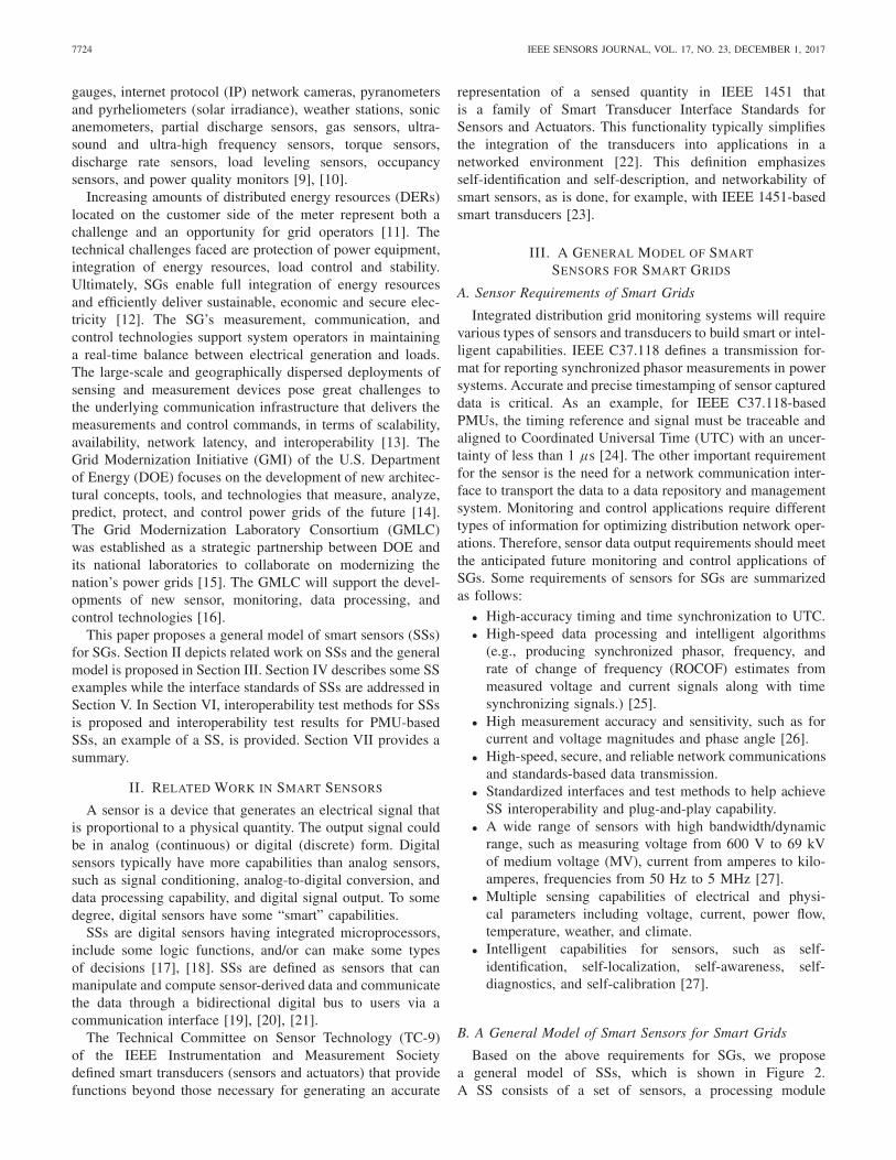
Based on the above requirements for SGs, we proposea general model of SSs, which is shown in Figure 2.A SS consists of a set of sensors, a processing module
SONG et al.: SSs AND STANDARD-BASED INTEROPERABILITY IN SGs 7725
Fig. 2. A general model for a SS for SGs.
with an internal clock connected with an optional externaltime reference, and a network communication module.The SS has four basic capabilities: 1) sensing by meansof sensors, 2) analog signal conditioning, analog-to-digitalconversion (ADC), and sensor data processing in processingmodule, 3) timing and synchronization by an internal clockwith optional external time reference, and 4) networkcommunications with the outside world through a networkcommunication module. The sensors produce electrical signalsbased on physical phenomena they measure, such as voltageand current of power lines in microgrids. The internal clockcan generate the timestamp for sensor data and synchronizewith the external time references, such as Global PositioningSystem (GPS), one pulse-per-second (1PPS), inter-rangeinstrumentation group-B (IRIG-B), IEEE 1588 PrecisionTime Protocol (PTP), or Network Time Protocol (NTP). Afterthe analog signals are scaled and conditioned in the processingmodule, an analog-to-digital converter (ADC) converts thesignals into digital form, and the processing module processesthe data based on the metadata and the application’s intelligentalgorithms, along with time synchronized to improve sensingand measurement accuracy. A network communicationmodule is used to communicate with the outside world, suchas sensor applications via wired (serial or Ethernet) or wireless(IEEE 802.11a/b/g/n, Worldwide Interoperability forMicrowave Access (WiMAX) or 3G/4G/ Long-TermEvolution (LTE)/5G cellular networks.
In addition to the four basic capabilities, SSs for SGs shouldhave additional intelligent capabilities, which depend on therequirements for specific sensors and applications [28]:
• Self-description [22]: The description about the sen-sor itself contained in a transducer electronic datasheet (TEDS) or configuration file.
• Self-identification [22], [23]: The sensor identificationinformation stored in electronic metadata in the sensoritself.
• Self-diagnostics [20]: The process of diagnosing or identi-fying conditions and errors performed by the sensor itself.
• Self-calibration [18], [20]: The calibration of the sensorperformed by itself without using an external reference.
• Self-testing [19]: Automatic testing performed by thesensor on itself. The sensor built-in test is a mechanismthat permits a sensor to test itself.
• Self-validation: Automatic validation performed by a sen-sor on data to ensure that it is valid always and reportserrors when detected. Self-adaptation [29]: Automaticadaptation to changes in the operating environment bya sensor.
Fig. 3. Block diagram of PMU-based SS.
• Location-awareness: Self-awareness of the physicalplacement of the sensor.
• Self-compensation [20]: Automatic compensation of out-puts due to temperature and environment changes in time.
• Multi-sensing and data fusion [18], [20]: sensing multiplephenomena using different sensing elements and perform-ing data fusion automatically.
IV. SMART SENSORS IN SMART GRIDS
SSs are sensors with built-in intelligence deployed inpower grids, which include temperature sensors, pressuresensors, humidity sensors, weather stations, current sensors,and voltage sensors, etc. SSs may communicate with theoutside world using standardized communication protocols,such as, IEEE 1451 family of Smart Transducer InterfaceStandards, IEEE 1815 Standard for Electric Power SystemsCommunications - Distributed Network Protocol (DNP3),IEEE C37.238 PTP Power Profile, and others. Descriptions ofsensing functions, applications, and network communicationsfor some specific SSs (e.g., PMU- and MU-based SSs) aregiven in the following subsections.
A. PMU-Based Smart Sensors
A phasor is the complex representation of a simple sinu-soidal quantity composed of the magnitude and the phase anglecomponents. A synchronized phasor is a phasor calculatedfrom sampled waveform data with a standardized time stampas the reference for the measurement. A PMU is a devicethat produces synchronized phasor, frequency, and ROCOFestimates from the input voltage and/or current signals togetherwith a time synchronizing reference signal [30]. PMUs providereal-time synchrophasor data for advanced applications, suchas wide-area situational awareness, state estimation, monitor-ing system dynamics, and validating system models.
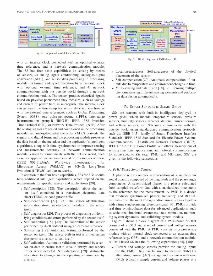
Figure 3 shows a block diagram of a PMU-based SS thatconsists of a PMU and a set of current and voltage sensorsconnected with the PMU. A PMU consists of a processingmodule with an internal clock connected to an external timereference (e.g., GPS), and a network communication module.A PMU-based SS has the following capabilities [24], [30]:
• Current and voltage sensors provide the analog inputsfor the PMU. They can be used to measure 50/60 Hzalternating current (AC) voltage and current waveforms.PMUs typically sample current and voltage phases at a
7726 IEEE SENSORS JOURNAL, VOL. 17, NO. 23, DECEMBER 1, 2017
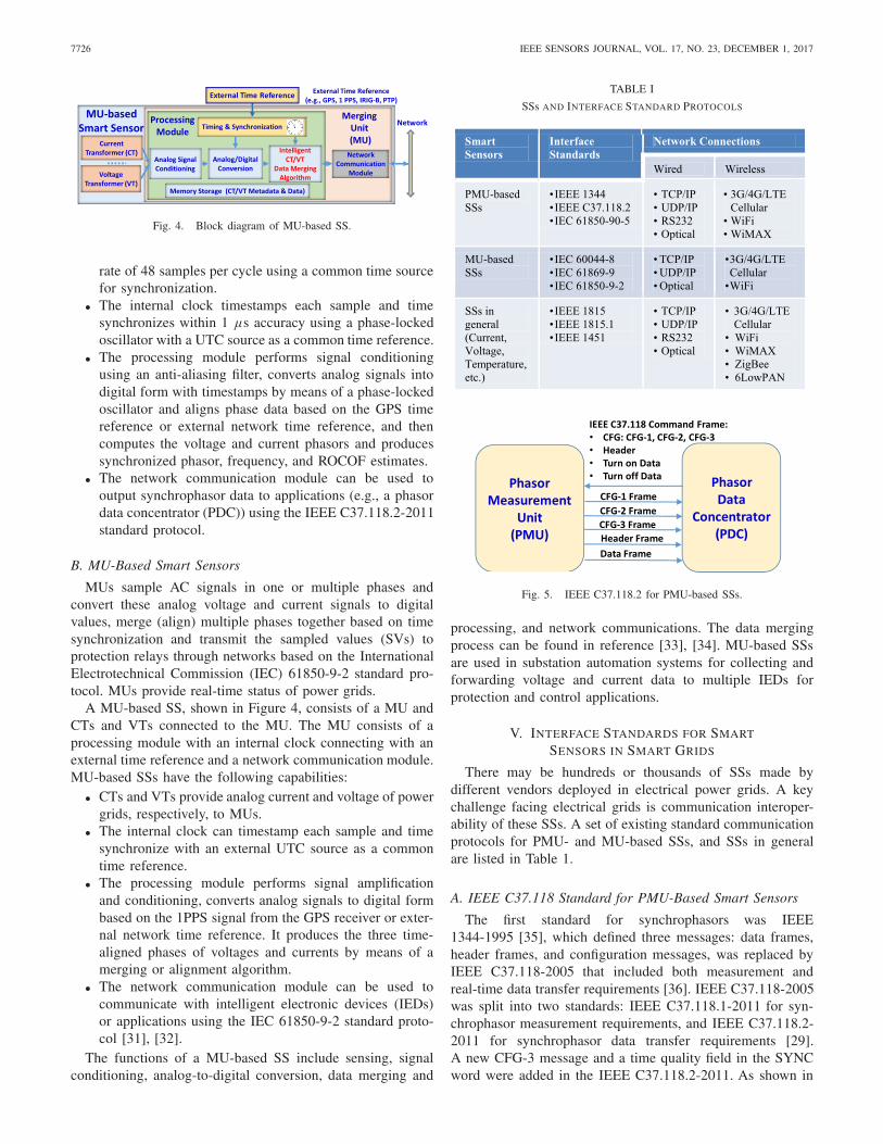
Fig. 4. Block diagram of MU-based SS.
rate of 48 samples per cycle using a common time sourcefor synchronization.
• The internal clock timestamps each sample and timesynchronizes within 1 µs accuracy using a phase-lockedoscillator with a UTC source as a common time reference.
• The processing module performs signal conditioningusing an anti-aliasing filter, converts analog signals intodigital form with timestamps by means of a phase-lockedoscillator and aligns phase data based on the GPS timereference or external network time reference, and thencomputes the voltage and current phasors and producessynchronized phasor, frequency, and ROCOF estimates.
• The network communication module can be used tooutput synchrophasor data to applications (e.g., a phasordata concentrator (PDC)) using the IEEE C37.118.2-2011standard protocol.
B. MU-Based Smart Sensors
MUs sample AC signals in one or multiple phases andconvert these analog voltage and current signals to digitalvalues, merge (align) multiple phases together based on timesynchronization and transmit the sampled values (SVs) toprotection relays through networks based on the InternationalElectrotechnical Commission (IEC) 61850-9-2 standard pro-tocol. MUs provide real-time status of power grids.
A MU-based SS, shown in Figure 4, consists of a MU andCTs and VTs connected to the MU. The MU consists of aprocessing module with an internal clock connecting with anexternal time reference and a network communication module.MU-based SSs have the following capabilities:
• CTs and VTs provide analog current and voltage of powergrids, respectively, to MUs.
• The internal clock can timestamp each sample and timesynchronize with an external UTC source as a commontime reference.
• The processing module performs signal amplificationand conditioning, converts analog signals to digital formbased on the 1PPS signal from the GPS receiver or exter-nal network time reference. It produces the three time-aligned phases of voltages and currents by means of amerging or alignment algorithm.
• The network communication module can be used tocommunicate with intelligent electronic devices (IEDs)or applications using the IEC 61850-9-2 standard proto-col [31], [32].
The functions of a MU-based SS include sensing, signalconditioning, analog-to-digital conversion, data merging and
TABLE I
SSs AND INTERFACE STANDARD PROTOCOLS
Fig. 5. IEEE C37.118.2 for PMU-based SSs.
processing, and network communications. The data mergingprocess can be found in reference [33], [34]. MU-based SSsare used in substation automation systems for collecting andforwarding voltage and current data to multiple IEDs forprotection and control applications.
V. INTERFACE STANDARDS FOR SMART
SENSORS IN SMART GRIDS
There may be hundreds or thousands of SSs made bydifferent vendors deployed in electrical power grids. A keychallenge facing electrical grids is communication interoper-ability of these SSs. A set of existing standard communicationprotocols for PMU- and MU-based SSs, and SSs in generalare listed in Table 1.
A. IEEE C37.118 Standard for PMU-Based Smart Sensors
The first standard for synchrophasors was IEEE1344-1995 [35], which defined three messages: data frames,header frames, and configuration messages, was replaced byIEEE C37.118-2005 that included both measurement andreal-time data transfer requirements [36]. IEEE C37.118-2005was split into two standards: IEEE C37.118.1-2011 for syn-chrophasor measurement requirements, and IEEE C37.118.2-2011 for synchrophasor data transfer requirements [29].A new CFG-3 message and a time quality field in the SYNCword were added in the IEEE C37.118.2-2011. As shown in
SONG et al.: SSs AND STANDARD-BASED INTEROPERABILITY IN SGs 7727
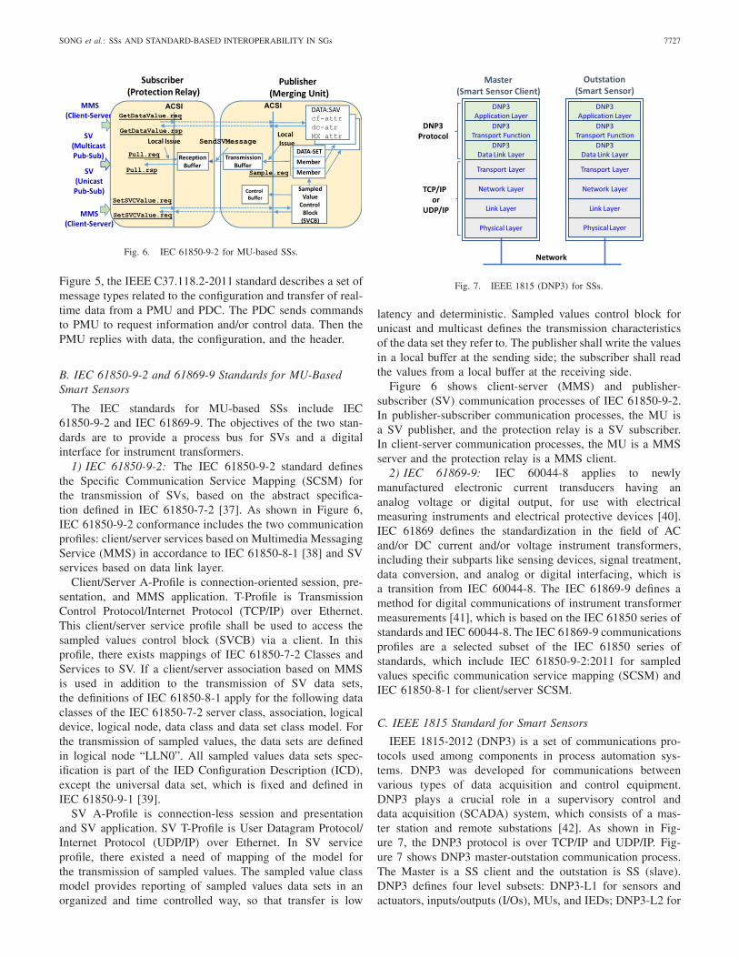
Fig. 6. IEC 61850-9-2 for MU-based SSs.
Figure 5, the IEEE C37.118.2-2011 standard describes a set ofmessage types related to the configuration and transfer of real-time data from a PMU and PDC. The PDC sends commandsto PMU to request information and/or control data. Then thePMU replies with data, the configuration, and the header.
B. IEC 61850-9-2 and 61869-9 Standards for MU-BasedSmart Sensors
The IEC standards for MU-based SSs include IEC61850-9-2 and IEC 61869-9. The objectives of the two stan-dards are to provide a process bus for SVs and a digitalinterface for instrument transformers.
1) IEC 61850-9-2: The IEC 61850-9-2 standard definesthe Specific Communication Service Mapping (SCSM) forthe transmission of SVs, based on the abstract specifica-tion defined in IEC 61850-7-2 [37]. As shown in Figure 6,IEC 61850-9-2 conformance includes the two communicationprofiles: client/server services based on Multimedia MessagingService (MMS) in accordance to IEC 61850-8-1 [38] and SVservices based on data link layer.
Client/Server A-Profile is connection-oriented session, pre-sentation, and MMS application. T-Profile is TransmissionControl Protocol/Internet Protocol (TCP/IP) over Ethernet.This client/server service profile shall be used to access thesampled values control block (SVCB) via a client. In thisprofile, there exists mappings of IEC 61850-7-2 Classes andServices to SV. If a client/server association based on MMSis used in addition to the transmission of SV data sets,the definitions of IEC 61850-8-1 apply for the following dataclasses of the IEC 61850-7-2 server class, association, logicaldevice, logical node, data class and data set class model. Forthe transmission of sampled values, the data sets are definedin logical node “LLN0”. All sampled values data sets spec-ification is part of the IED Configuration Description (ICD),except the universal data set, which is fixed and defined inIEC 61850-9-1 [39].
SV A-Profile is connection-less session and presentationand SV application. SV T-Profile is User Datagram Protocol/Internet Protocol (UDP/IP) over Ethernet. In SV serviceprofile, there existed a need of mapping of the model forthe transmission of sampled values. The sampled value classmodel provides reporting of sampled values data sets in anorganized and time controlled way, so that transfer is low
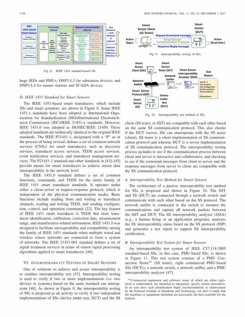
Fig. 7. IEEE 1815 (DNP3) for SSs.
latency and deterministic. Sampled values control block forunicast and multicast defines the transmission characteristicsof the data set they refer to. The publisher shall write the valuesin a local buffer at the sending side; the subscriber shall readthe values from a local buffer at the receiving side.
Figure 6 shows client-server (MMS) and publisher-subscriber (SV) communication processes of IEC 61850-9-2.In publisher-subscriber communication processes, the MU isa SV publisher, and the protection relay is a SV subscriber.In client-server communication processes, the MU is a MMSserver and the protection relay is a MMS client.
2) IEC 61869-9: IEC 60044-8 applies to newlymanufactured electronic current transducers having ananalog voltage or digital output, for use with electricalmeasuring instruments and electrical protective devices [40].IEC 61869 defines the standardization in the field of ACand/or DC current and/or voltage instrument transformers,including their subparts like sensing devices, signal treatment,data conversion, and analog or digital interfacing, which isa transition from IEC 60044-8. The IEC 61869-9 defines amethod for digital communications of instrument transformermeasurements [41], which is based on the IEC 61850 series ofstandards and IEC 60044-8. The IEC 61869-9 communicationsprofiles are a selected subset of the IEC 61850 series ofstandards, which include IEC 61850-9-2:2011 for sampledvalues specific communication service mapping (SCSM) andIEC 61850-8-1 for client/server SCSM.
C. IEEE 1815 Standard for Smart Sensors
IEEE 1815-2012 (DNP3) is a set of communications pro-tocols used among components in process automation sys-tems. DNP3 was developed for communications betweenvarious types of data acquisition and control equipment.DNP3 plays a crucial role in a supervisory control anddata acquisition (SCADA) system, which consists of a mas-ter station and remote substations [42]. As shown in Fig-ure 7, the DNP3 protocol is over TCP/IP and UDP/IP. Fig-ure 7 shows DNP3 master-outstation communication process.The Master is a SS client and the outstation is SS (slave).DNP3 defines four level subsets: DNP3-L1 for sensors andactuators, inputs/outputs (I/Os), MUs, and IEDs; DNP3-L2 for
7728 IEEE SENSORS JOURNAL, VOL. 17, NO. 23, DECEMBER 1, 2017
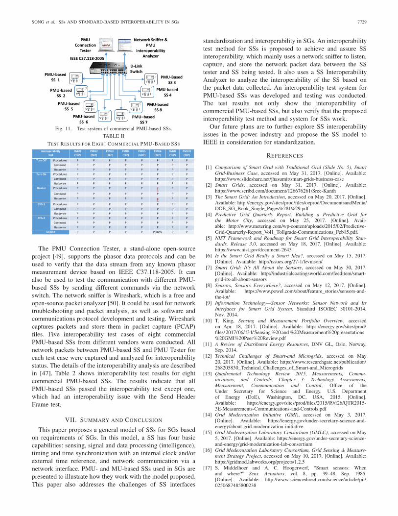
Fig. 8. IEEE 1451 standard-based SS.
large IEDs and PMUs; DNP3-L3 for substation devices; andDNP3-L4 for master stations and SCADA devices.
D. IEEE 1451 Standard for Smart Sensors
The IEEE 1451-based smart transducers, which includeSSs and smart actuators, are shown in Figure 8. Some IEEE1451.x standards have been adopted as International Orga-nization for Standardization (ISO)/International Electrotech-nical Commission (IEC)/IEEE 21451-x standards. However,IEEE 1451.0 was adopted as ISO/IEC/IEEE 21450. Theseadopted standards are technically identical to the original IEEEstandards. The IEEE P21451-1, designated with a “P” as inthe process of being revised, defines a set of common networkservices (CNSs) for smart transducers, such as discoveryservices, transducer access services, TEDS access services,event notification services, and transducer management ser-vices. The P21451-1 standard and other standards in [43]–[45]provide means for smart transducers to achieve sensor datainteroperability in the network level.
The IEEE 1451.0 standard defines a set of commonfunctions, commands, and TEDS for the entire family ofIEEE 1451 smart transducer standards. It operates undereither a client-server or request-response protocol, which isindependent of the physical communication media. Basicfunctions include reading from and writing to transducerchannels, reading and writing TEDS, and sending configura-tion, control, and operation commands [22]. The key featureof IEEE 1451 smart transducer is TEDS that store trans-ducer identification, calibration, correction data, measurementrange, and manufacturer-related information. IEEE 1451.0 wasdesigned to facilitate interoperability and compatibility amongthe family of IEEE 1451 standards when multiple wired andwireless sensor networks are connected to form a systemof networks. The IEEE 21451-001 standard defines a set ofsignal treatment services in terms of sensor signal processingalgorithms applied to smart transducers [46].
VI. INTEROPERABILITY TESTING OF SMART SENSORS
One of solutions to achieve and assure interoperability isto conduct interoperability test [47]. Interoperability testingis used to verify if two or more implementations (i.e. twodevices or systems) based on the same standard can interop-erate [48]. As shown in Figure 9, the interoperability testingof SSs is proposed as an activity to verify if two independentimplementations of SSs (device under test, DUT) and the SS
Fig. 9. Interoperability testing of SSs.
Fig. 10. Interoperability test method of SSs.
client (SS tester, or SST) are compatible with each other basedon the same SS communication protocol. This also checksif the DUT (server, SS) can interoperate with the SS tester(client). SS tester is a client implementation of SS communi-cation protocol and whereas DUT is a server implementationof SS communication protocol. The interoperability testingprocess includes to see if the communication process betweenclient and server is interactive and collaborative, and checkingto see if the command messages from client to server and theresponse messages from server to client are compatible withthe SS communication protocol.
A. Interoperability Test Method for Smart Sensors
The architecture of a passive interoperability test methodfor SSs is proposed and shown in Figure 10. The SSTand SS (DUT) are connected through a network switch andcommunicate with each other based on the SS protocol. Thenetwork sniffer is connected to the switch to monitor thecommunications and capture all network packets betweenthe SST and DUT. The SS interoperability analyzer (SSIA)(e.g., a human being or an application program), analyzesthe SS interoperability status based on the SS protocol (SSP)and generates a test report to support SS interoperabilitycertification.
B. Interoperability Test System for Smart Sensors
An interoperability test system of IEEE C37.118-2005standard-based SSs, in this case, PMU-based SSs, is shownin Figure 11. This test system consists of a PMU Con-nection Tester∗∗ (SS tester), eight commercial PMU-basedSSs (DUTs), a network switch, a network sniffer, and a PMUinteroperability analyzer [47].
∗∗Commercial equipment and software, many of which are either regis-tered or trademarked, are identified to adequately specify certain procedures.In no case does such identification imply recommendation or endorsementby the National Institute of Standards and Technology, nor does it imply thatthe materials or equipment identified are necessarily the best available for thepurpose.
SONG et al.: SSs AND STANDARD-BASED INTEROPERABILITY IN SGs 7729
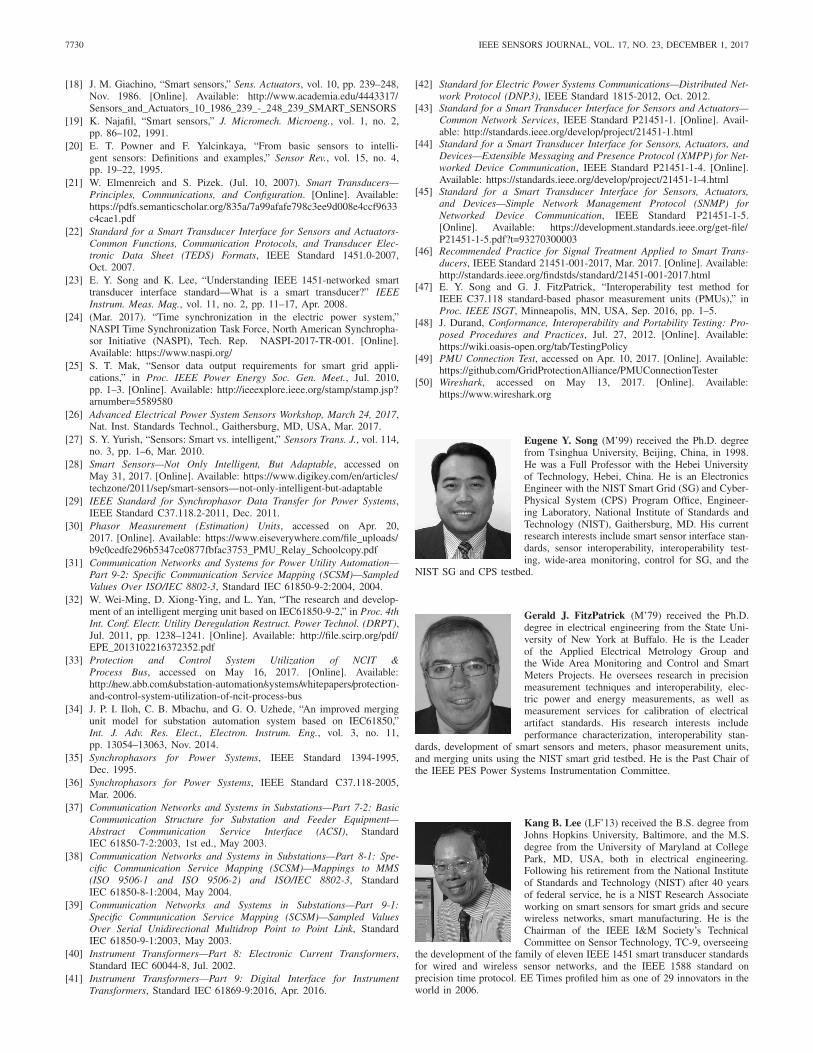
Fig. 11. Test system of commercial PMU-based SSs.
TABLE II
TEST RESULTS FOR EIGHT COMMERCIAL PMU-BASED SSS
The PMU Connection Tester, a stand-alone open-sourceproject [49], supports the phasor data protocols and can beused to verify that the data stream from any known phasormeasurement device based on IEEE C37.118-2005. It canalso be used to test the communication with different PMU-based SSs by sending different commands via the networkswitch. The network sniffer is Wireshark, which is a free andopen-source packet analyzer [50]. It could be used for networktroubleshooting and packet analysis, as well as software andcommunications protocol development and testing. Wiresharkcaptures packets and store them in packet capture (PCAP)files. Five interoperability test cases of eight commercialPMU-based SSs from different vendors were conducted. Allnetwork packets between PMU-based SS and PMU Tester foreach test case were captured and analyzed for interoperabilitystatus. The details of the interoperability analysis are describedin [47]. Table 2 shows interoperability test results for eightcommercial PMU-based SSs. The results indicate that allPMU-based SSs passed the interoperability test except one,which had an interoperability issue with the Send HeaderFrame test.
VII. SUMMARY AND CONCLUSION
This paper proposes a general model of SSs for SGs basedon requirements of SGs. In this model, a SS has four basiccapabilities: sensing, signal and data processing (intelligence),timing and time synchronization with an internal clock and/orexternal time reference, and network communication via anetwork interface. PMU- and MU-based SSs used in SGs arepresented to illustrate how they work with the model proposed.This paper also addresses the challenges of SS interfaces
standardization and interoperability in SGs. An interoperabilitytest method for SSs is proposed to achieve and assure SSinteroperability, which mainly uses a network sniffer to listen,capture, and store the network packet data between the SStester and SS being tested. It also uses a SS InteroperabilityAnalyzer to analyze the interoperability of the SS based onthe packet data collected. An interoperability test system forPMU-based SSs was developed and testing was conducted.The test results not only show the interoperability ofcommercial PMU-based SSs, but also verify that the proposedinteroperability test method and system for SSs work.
Our future plans are to further explore SS interoperabilityissues in the power industry and propose the SS model toIEEE in consideration for standardization.
REFERENCES
[1] Comparison of Smart Grid with Traditional Grid (Slide No. 5), SmartGrid-Business Case, accessed on May 31, 2017. [Online]. Available:https://www.slideshare.net/jhasumit/smart-grids-business-case
[2] Smart Grids, accessed on May 31, 2017. [Online]. Available:https://www.scribd.com/document/126676261/Sree-Kanth
[3] The Smart Grid: An Introduction, accessed on May 20, 2017. [Online].Available: http://energy.gov/sites/prod/files/oeprod/DocumentsandMedia/DOE_SG_Book_Single_Pages%281%29.pdf
[4] Predictive Grid Quarterly Report, Building a Predictive Grid forthe Motor City, accessed on May 25, 2017. [Online]. Avail-able: http://www.metering.com/wp-content/uploads/2015/02/Predictive-Grid-Quarterly-Report_Vol1_Tollgrade-Communications_Feb15.pdf.
[5] NIST Framework and Roadmap for Smart Grid Interoperability Stan-dards, Release 3.0, accessed on May 18, 2017. [Online]. Available:https://www.nist.gov/document-2643
[6] Is the Smart Grid Really a Smart Idea?, accessed on May 15, 2017.[Online]. Available: http://issues.org/27-1/levinson/
[7] Smart Grid: It’s All About the Sensors, accessed on May 30, 2017.[Online]. Available: http://industrialcoatingsworld.com/feeditem/smart-grid-its-all-about-sensors
[8] Sensors, Sensors Everywhere?, accessed on May 12, 2017. [Online].Available: https://www.powel.com/about/feature_stories/sensors-and-the-iot/
[9] Information Technology—Sensor Networks: Sensor Network and ItsInterfaces for Smart Grid System, Standard ISO/IEC 30101-2014,Nov. 2014.
[10] T. King, Sensing and Measurement Portfolio Overview, accessedon Apr. 18, 2017. [Online]. Available: https://energy.gov/sites/prod/files/ 2017/ 06/ f34/ Sensing %20 and %20Measurement%20presentations%20GMI%20Peer%20Review.pdf
[11] A Review of Distributed Energy Resources, DNV GL, Oslo, Norway,Sep. 2014.
[12] Technical Challenges of Smart-and Microgrids, accessed on May20, 2017. [Online]. Available: https://www.researchgate.net/publication/268205830_Technical_Challenges_of_Smart-and_Microgrids
[13] Quadrennial Technology Review 2015, Measurements, Commu-nications, and Controls, Chapter 3: Technology Assessments,Measurement, Communication and Control, Office of theUnder Secretary for Science and Energy, U.S. Departmentof Energy (DoE), Washington, DC, USA, 2015. [Online].Available: https://energy.gov/sites/prod/files/2015/09/f26/QTR2015-3E-Measurements-Communications-and-Controls.pdf
[14] Grid Modernization Initiative (GMI), accessed on May 3, 2017.[Online]. Available: https://energy.gov/under-secretary-science-and-energy/about-grid-modernization-initiative
[15] Grid Modernization Laboratory Consortium (GMLC), accessed on May5, 2017. [Online]. Available: https://energy.gov/under-secretary-science-and-energy/grid-modernization-lab-consortium
[16] Grid Modernization Laboratory Consortium, Grid Sensing & Measure-ment Strategy Project, accessed on May 10, 2017. [Online]. Available:https://gridmod.labworks.org/projects/1.2.5
[17] S. Middelhoer and A. C. Hoogerwerf, “Smart sensors: Whenand where?” Sens. Actuators, vol. 8, pp. 39–48, Sep. 1985.[Online]. Available: http://www.sciencedirect.com/science/article/pii/0250687485800238
7730 IEEE SENSORS JOURNAL, VOL. 17, NO. 23, DECEMBER 1, 2017
[18] J. M. Giachino, “Smart sensors,” Sens. Actuators, vol. 10, pp. 239–248,Nov. 1986. [Online]. Available: http://www.academia.edu/4443317/Sensors_and_Actuators_10_1986_239_-_248_239_SMART_SENSORS
[19] K. Najafil, “Smart sensors,” J. Micromech. Microeng., vol. 1, no. 2,pp. 86–102, 1991.
[20] E. T. Powner and F. Yalcinkaya, “From basic sensors to intelli-gent sensors: Definitions and examples,” Sensor Rev., vol. 15, no. 4,pp. 19–22, 1995.
[21] W. Elmenreich and S. Pizek. (Jul. 10, 2007). Smart Transducers—Principles, Communications, and Configuration. [Online]. Available:https://pdfs.semanticscholar.org/835a/7a99afafe798c3ee9d008e4ccf9633c4cae1.pdf
[22] Standard for a Smart Transducer Interface for Sensors and Actuators-Common Functions, Communication Protocols, and Transducer Elec-tronic Data Sheet (TEDS) Formats, IEEE Standard 1451.0-2007,Oct. 2007.
[23] E. Y. Song and K. Lee, “Understanding IEEE 1451-networked smarttransducer interface standard—What is a smart transducer?” IEEEInstrum. Meas. Mag., vol. 11, no. 2, pp. 11–17, Apr. 2008.
[24] (Mar. 2017). “Time synchronization in the electric power system,”NASPI Time Synchronization Task Force, North American Synchropha-sor Initiative (NASPI), Tech. Rep. NASPI-2017-TR-001. [Online].Available: https://www.naspi.org/
[25] S. T. Mak, “Sensor data output requirements for smart grid appli-cations,” in Proc. IEEE Power Energy Soc. Gen. Meet., Jul. 2010,pp. 1–3. [Online]. Available: http://ieeexplore.ieee.org/stamp/stamp.jsp?arnumber=5589580
[26] Advanced Electrical Power System Sensors Workshop, March 24, 2017,Nat. Inst. Standards Technol., Gaithersburg, MD, USA, Mar. 2017.
[27] S. Y. Yurish, “Sensors: Smart vs. intelligent,” Sensors Trans. J., vol. 114,no. 3, pp. 1–6, Mar. 2010.
[28] Smart Sensors—Not Only Intelligent, But Adaptable, accessed onMay 31, 2017. [Online]. Available: https://www.digikey.com/en/articles/techzone/2011/sep/smart-sensors—not-only-intelligent-but-adaptable
[29] IEEE Standard for Synchrophasor Data Transfer for Power Systems,IEEE Standard C37.118.2-2011, Dec. 2011.
[30] Phasor Measurement (Estimation) Units, accessed on Apr. 20,2017. [Online]. Available: https://www.eiseverywhere.com/file_uploads/b9c0cedfe296b5347ce0877fbfac3753_PMU_Relay_Schoolcopy.pdf
[31] Communication Networks and Systems for Power Utility Automation—Part 9-2: Specific Communication Service Mapping (SCSM)—SampledValues Over ISO/IEC 8802-3, Standard IEC 61850-9-2:2004, 2004.
[32] W. Wei-Ming, D. Xiong-Ying, and L. Yan, “The research and develop-ment of an intelligent merging unit based on IEC61850-9-2,” in Proc. 4thInt. Conf. Electr. Utility Deregulation Restruct. Power Technol. (DRPT),Jul. 2011, pp. 1238–1241. [Online]. Available: http://file.scirp.org/pdf/EPE_2013102216372352.pdf
[33] Protection and Control System Utilization of NCIT &Process Bus, accessed on May 16, 2017. [Online]. Available:http://new.abb.com/substation-automation/systems/whitepapers/protection-and-control-system-utilization-of-ncit-process-bus
[34] J. P. I. Iloh, C. B. Mbachu, and G. O. Uzhede, “An improved mergingunit model for substation automation system based on IEC61850,”Int. J. Adv. Res. Elect., Electron. Instrum. Eng., vol. 3, no. 11,pp. 13054–13063, Nov. 2014.
[35] Synchrophasors for Power Systems, IEEE Standard 1394-1995,Dec. 1995.
[36] Synchrophasors for Power Systems, IEEE Standard C37.118-2005,Mar. 2006.
[37] Communication Networks and Systems in Substations—Part 7-2: BasicCommunication Structure for Substation and Feeder Equipment—Abstract Communication Service Interface (ACSI), StandardIEC 61850-7-2:2003, 1st ed., May 2003.
[38] Communication Networks and Systems in Substations—Part 8-1: Spe-cific Communication Service Mapping (SCSM)—Mappings to MMS(ISO 9506-1 and ISO 9506-2) and ISO/IEC 8802-3, StandardIEC 61850-8-1:2004, May 2004.
[39] Communication Networks and Systems in Substations—Part 9-1:Specific Communication Service Mapping (SCSM)—Sampled ValuesOver Serial Unidirectional Multidrop Point to Point Link, StandardIEC 61850-9-1:2003, May 2003.
[40] Instrument Transformers—Part 8: Electronic Current Transformers,Standard IEC 60044-8, Jul. 2002.
[41] Instrument Transformers—Part 9: Digital Interface for InstrumentTransformers, Standard IEC 61869-9:2016, Apr. 2016.
[42] Standard for Electric Power Systems Communications—Distributed Net-work Protocol (DNP3), IEEE Standard 1815-2012, Oct. 2012.
[43] Standard for a Smart Transducer Interface for Sensors and Actuators—Common Network Services, IEEE Standard P21451-1. [Online]. Avail-able: http://standards.ieee.org/develop/project/21451-1.html
[44] Standard for a Smart Transducer Interface for Sensors, Actuators, andDevices—Extensible Messaging and Presence Protocol (XMPP) for Net-worked Device Communication, IEEE Standard P21451-1-4. [Online].Available: https://standards.ieee.org/develop/project/21451-1-4.html
[45] Standard for a Smart Transducer Interface for Sensors, Actuators,and Devices—Simple Network Management Protocol (SNMP) forNetworked Device Communication, IEEE Standard P21451-1-5.[Online]. Available: https://development.standards.ieee.org/get-file/P21451-1-5.pdf?t=93270300003
[46] Recommended Practice for Signal Treatment Applied to Smart Trans-ducers, IEEE Standard 21451-001-2017, Mar. 2017. [Online]. Available:http://standards.ieee.org/findstds/standard/21451-001-2017.html
[47] E. Y. Song and G. J. FitzPatrick, “Interoperability test method forIEEE C37.118 standard-based phasor measurement units (PMUs),” inProc. IEEE ISGT, Minneapolis, MN, USA, Sep. 2016, pp. 1–5.
[48] J. Durand, Conformance, Interoperability and Portability Testing: Pro-posed Procedures and Practices, Jul. 27, 2012. [Online]. Available:https://wiki.oasis-open.org/tab/TestingPolicy
[49] PMU Connection Test, accessed on Apr. 10, 2017. [Online]. Available:https://github.com/GridProtectionAlliance/PMUConnectionTester
[50] Wireshark, accessed on May 13, 2017. [Online]. Available:https://www.wireshark.org
Eugene Y. Song (M’99) received the Ph.D. degreefrom Tsinghua University, Beijing, China, in 1998.He was a Full Professor with the Hebei Universityof Technology, Hebei, China. He is an ElectronicsEngineer with the NIST Smart Grid (SG) and Cyber-Physical System (CPS) Program Office, Engineer-ing Laboratory, National Institute of Standards andTechnology (NIST), Gaithersburg, MD. His currentresearch interests include smart sensor interface stan-dards, sensor interoperability, interoperability test-ing, wide-area monitoring, control for SG, and the
NIST SG and CPS testbed.
Gerald J. FitzPatrick (M’79) received the Ph.D.degree in electrical engineering from the State Uni-versity of New York at Buffalo. He is the Leaderof the Applied Electrical Metrology Group andthe Wide Area Monitoring and Control and SmartMeters Projects. He oversees research in precisionmeasurement techniques and interoperability, elec-tric power and energy measurements, as well asmeasurement services for calibration of electricalartifact standards. His research interests includeperformance characterization, interoperability stan-
dards, development of smart sensors and meters, phasor measurement units,and merging units using the NIST smart grid testbed. He is the Past Chair ofthe IEEE PES Power Systems Instrumentation Committee.
Kang B. Lee (LF’13) received the B.S. degree fromJohns Hopkins University, Baltimore, and the M.S.degree from the University of Maryland at CollegePark, MD, USA, both in electrical engineering.Following his retirement from the National Instituteof Standards and Technology (NIST) after 40 yearsof federal service, he is a NIST Research Associateworking on smart sensors for smart grids and securewireless networks, smart manufacturing. He is theChairman of the IEEE I&M Society’s TechnicalCommittee on Sensor Technology, TC-9, overseeing
the development of the family of eleven IEEE 1451 smart transducer standardsfor wired and wireless sensor networks, and the IEEE 1588 standard onprecision time protocol. EE Times profiled him as one of 29 innovators in theworld in 2006.