Embed Size (px)
Citation preview
IEEE S b t ti C itt M tiAnders Sjoelin, ABB Power Systems
IEEE Substations Committee MeetingSubstation Concepts for the Future
© ABB Group April 26, 2012 | Slide 1
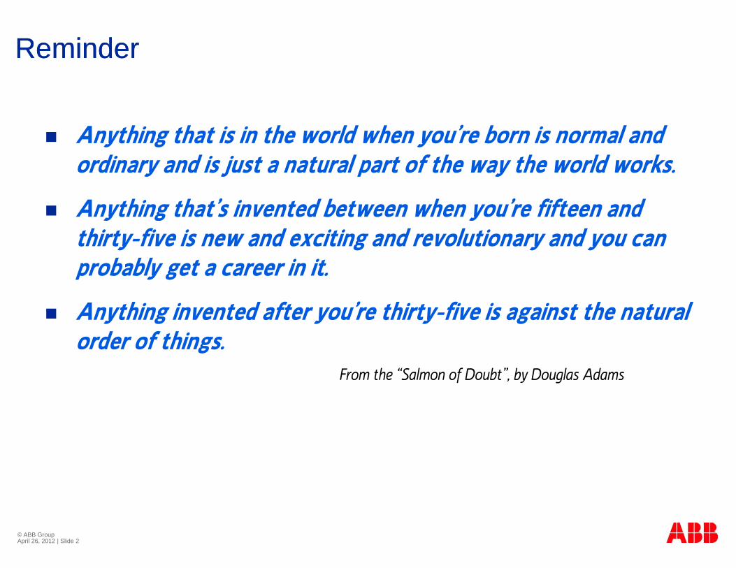
ReminderReminder
Anything that is in the world when you’re born is normal and y g yordinary and is just a natural part of the way the world works.
Anything that’s invented between when you’re fifteen and Anything that s invented between when you re fifteen andthirty-five is new and exciting and revolutionary and you can probably get a career in it.
Anything invented after you’re thirty-five is against the natural order of things.g
From the “Salmon of Doubt”, by Douglas Adams
© ABB Group April 26, 2012 | Slide 2
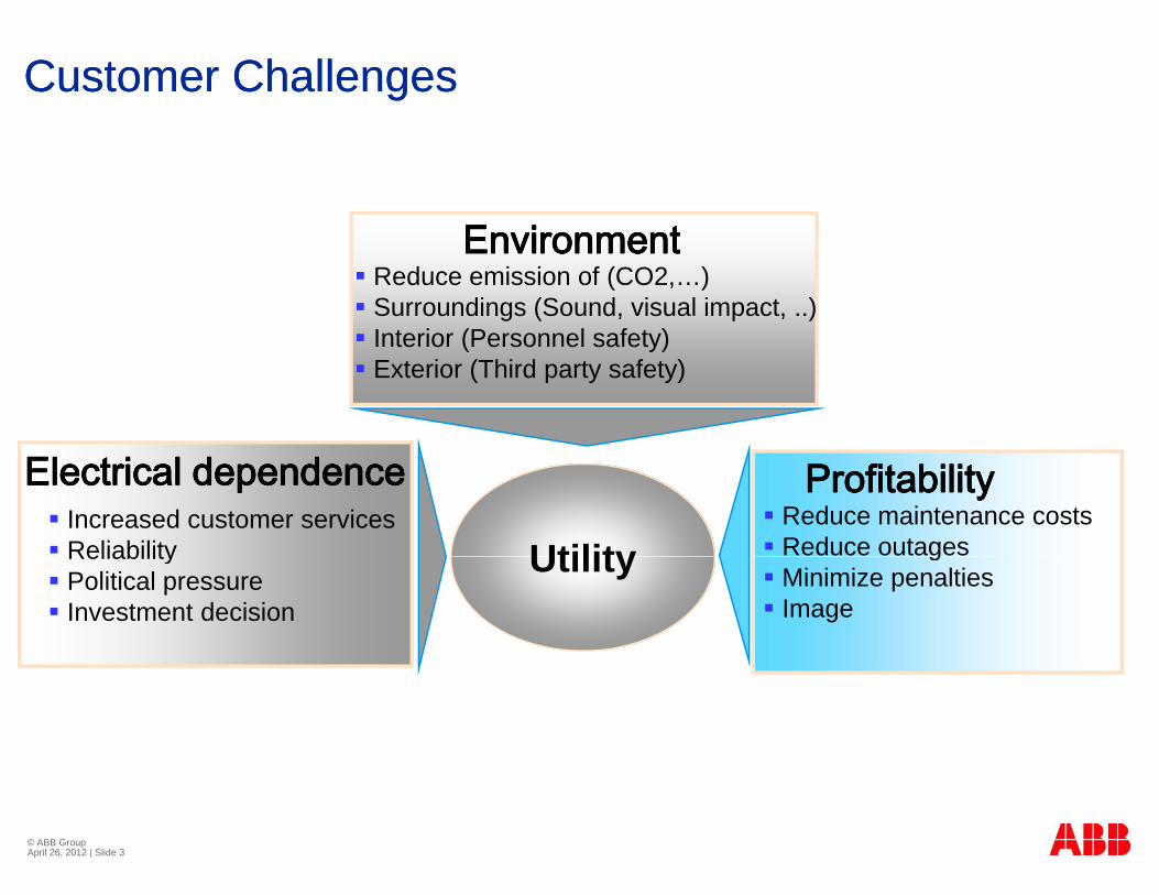
Customer ChallengesCustomer Challenges
E i tE i t Reduce emission of (CO2,…) Surroundings (Sound, visual impact, ..) Interior (Personnel safety)
EnvironmentEnvironment
Interior (Personnel safety) Exterior (Third party safety)
Utility Reduce maintenance costs Reduce outages
ProfitabilityProfitability Increased customer services Reliability
Electrical dependenceElectrical dependence
Utility g Minimize penalties Image
Reliability Political pressure Investment decision
© ABB Group April 26, 2012 | Slide 3
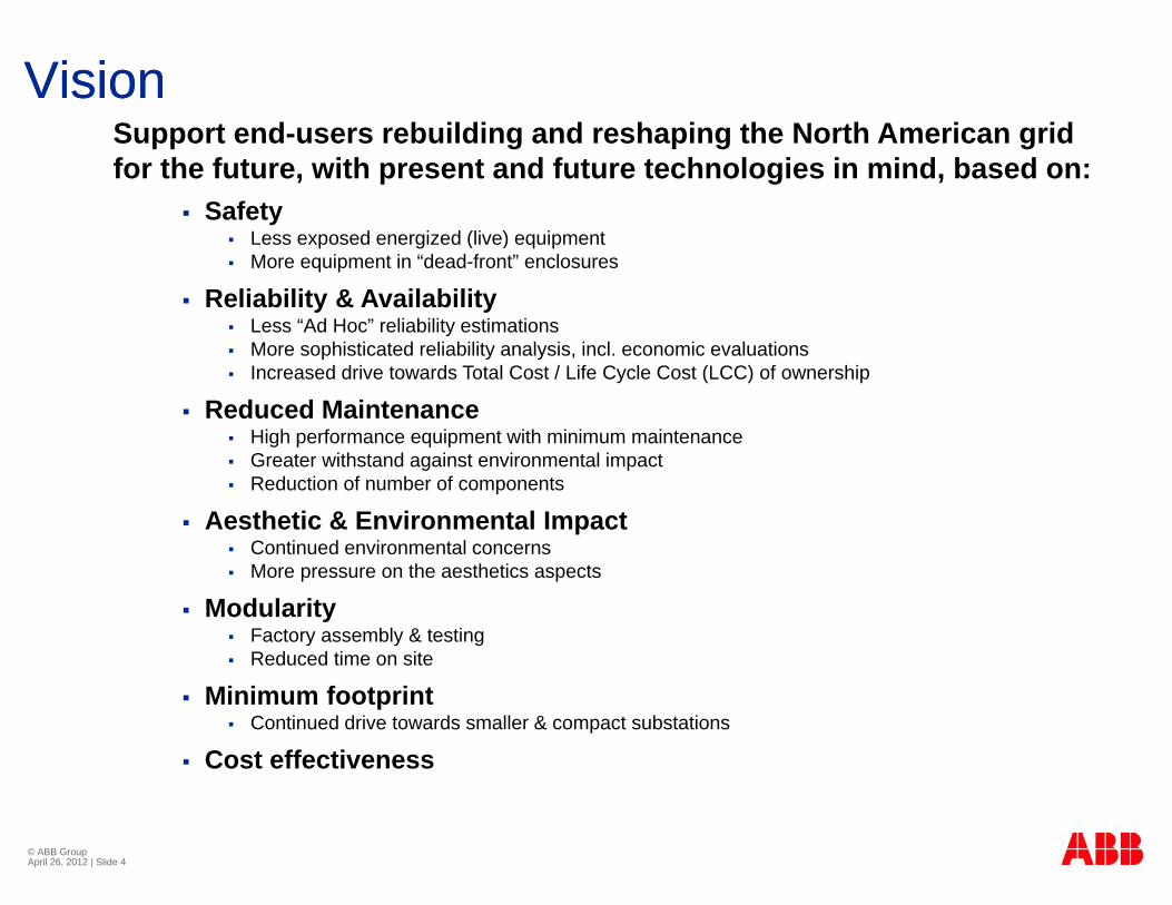
VisionVisionS t d b ildi d h i th N th A i idSupport end-users rebuilding and reshaping the North American grid for the future, with present and future technologies in mind, based on:
SafetyL d i d (li ) i t Less exposed energized (live) equipment
More equipment in “dead-front” enclosures
Reliability & Availability Less “Ad Hoc” reliability estimations
M hi ti t d li bilit l i i l i l ti More sophisticated reliability analysis, incl. economic evaluations Increased drive towards Total Cost / Life Cycle Cost (LCC) of ownership
Reduced Maintenance High performance equipment with minimum maintenance
G i h d i i l i Greater withstand against environmental impact Reduction of number of components
Aesthetic & Environmental Impact Continued environmental concerns More pressure on the aesthetics aspects
Modularity Factory assembly & testing Reduced time on site
Minimum footprint Continued drive towards smaller & compact substations
Cost effectiveness
© ABB Group April 26, 2012 | Slide 4
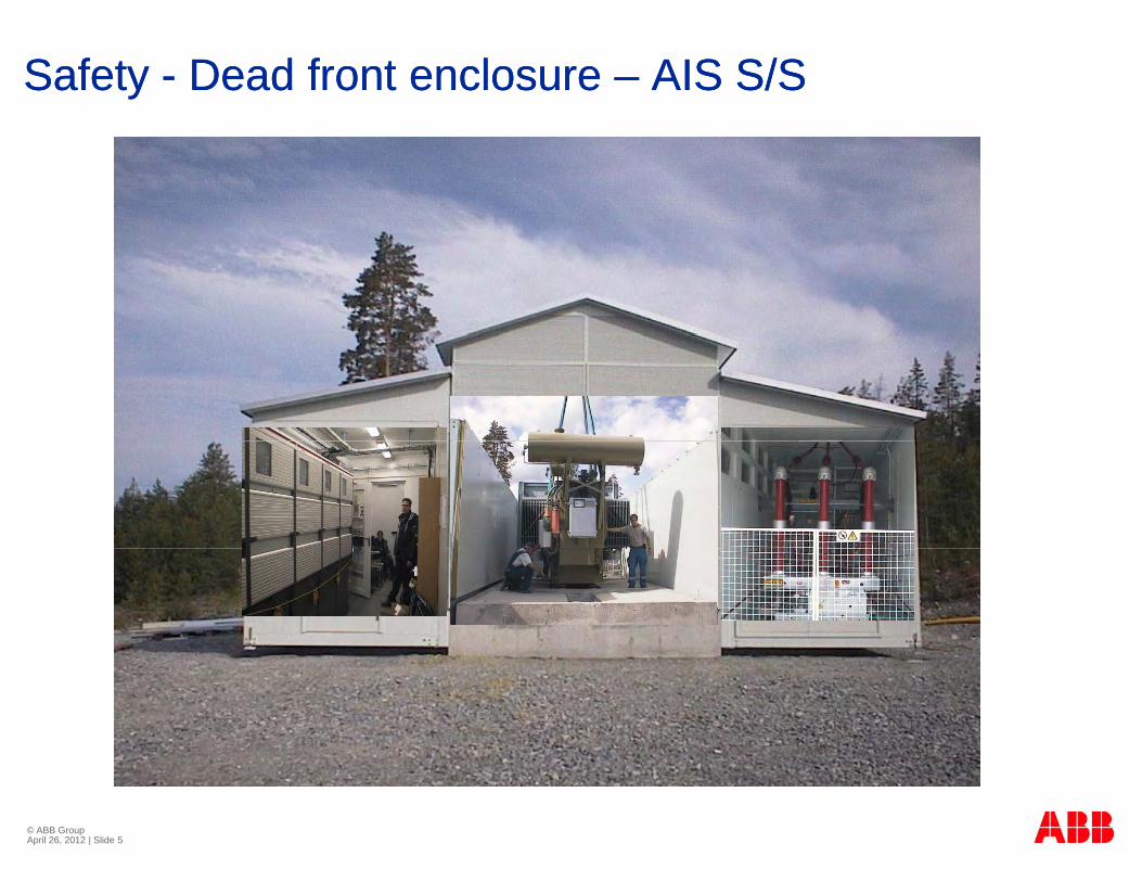
Safety Safety -- Dead front enclosure Dead front enclosure –– AIS S/SAIS S/S
© ABB Group April 26, 2012 | Slide 5
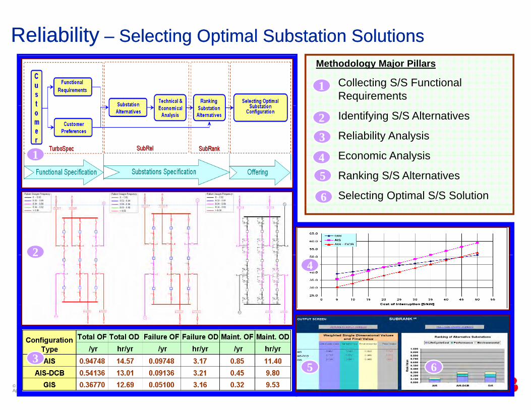
ReliabilityReliability –– Selecting Optimal Substation SolutionsSelecting Optimal Substation SolutionsMethodology Major Pillars
Collecting S/S Functional Requirements
1
Identifying S/S Alternatives
Reliability Analysis
Economic Analysis
23
41 Economic Analysis
Ranking S/S Alternatives
Selecting Optimal S/S Solution
45
6
1
224
3
© ABB Group April 26, 2012 | Slide 6
35 6
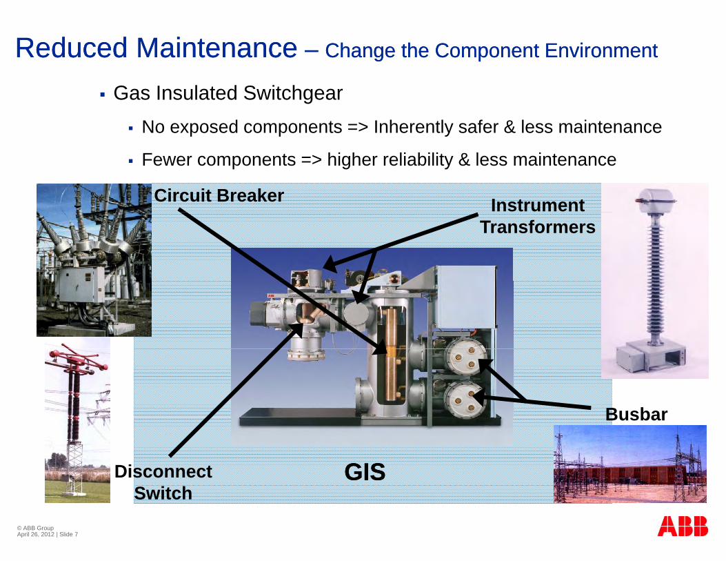
Reduced MaintenanceReduced Maintenance –– Change the Component EnvironmentChange the Component Environment
Gas Insulated Switchgear No exposed components => Inherently safer & less maintenance
Fewer components => higher reliability & less maintenance
InstrumentCircuit BreakerTransformers
BusbarBusbar
GISGISDisconnect
© ABB Group April 26, 2012 | Slide 7
Switch
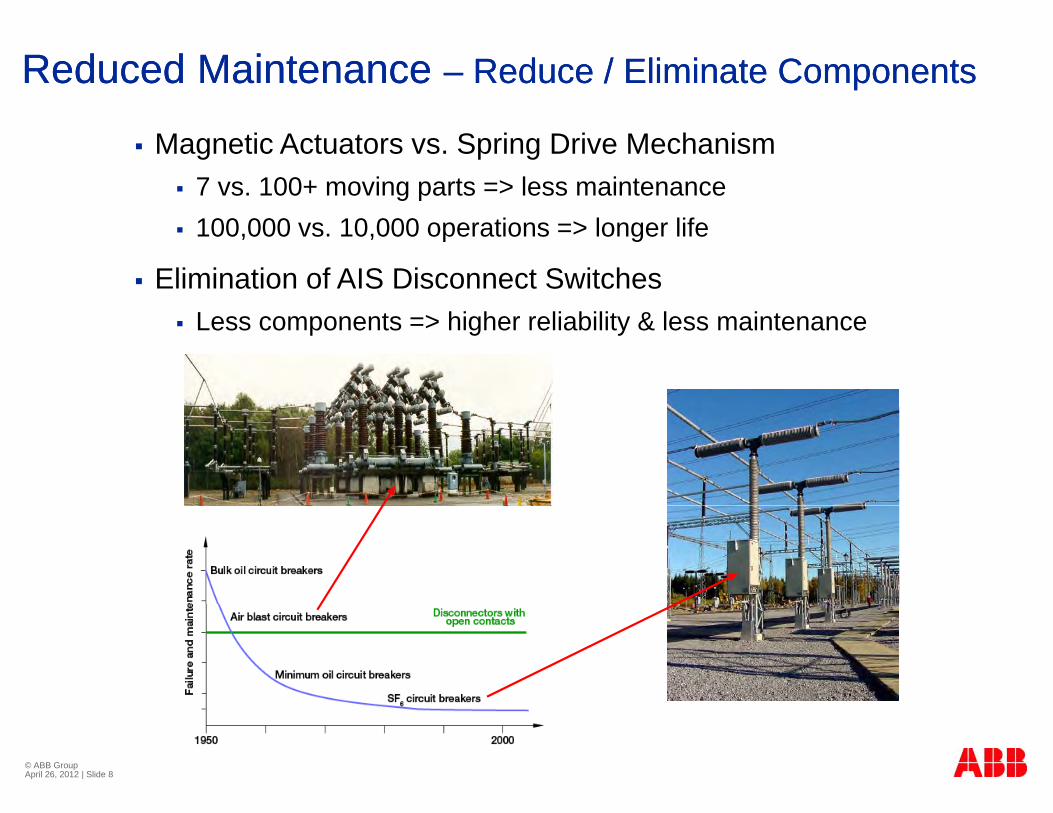
Reduced Maintenance Reduced Maintenance –– Reduce / Eliminate ComponentsReduce / Eliminate Components
Magnetic Actuators vs. Spring Drive Mechanism 7 vs. 100+ moving parts => less maintenance 100,000 vs. 10,000 operations => longer life
Elimination of AIS Disconnect Switches Less components => higher reliability & less maintenance
© ABB Group April 26, 2012 | Slide 8
Minimum FootprintMinimum FootprintMinimum FootprintMinimum Footprint
Continuous drive towards compact substations:Continuous drive towards compact substations: Space savings / utilize available spaceSpace savings / utilize available space
Cost reductionsCost reductionsCost reductionsCost reductions
Minimized aesthetic impactMinimized aesthetic impact
Enabling future relocationEnabling future relocation
© ABB Group April 26, 2012 | Slide 9
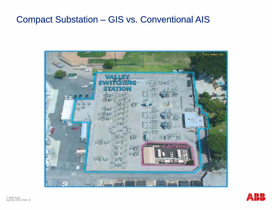
Compact Substation Compact Substation –– GIS vs. Conventional AISGIS vs. Conventional AIS
© ABB Group April 26, 2012 | Slide 10
Modular ApproachModular Approach
PrePre--Engineered PreEngineered Pre--Fabricated and FactoryFabricated and Factory
Modular ApproachModular Approach
PrePre--Engineered, PreEngineered, Pre--Fabricated and Factory Fabricated and Factory Tested “Modules” with well defined interfaces.Tested “Modules” with well defined interfaces.
C t i i d h HV (GIS) d MV i tC t i i d h HV (GIS) d MV i t Containerized approach, HV (GIS) and MV equipmentContainerized approach, HV (GIS) and MV equipment
“Kiosk” approach for protection, control & monitoring “Kiosk” approach for protection, control & monitoring systemssystems
Benefits:Benefits: Reduced time on site for construction, installation & testingReduced time on site for construction, installation & testing
Factory tested => Reduction of mistakes on siteacto y tested educt o o sta es o s te
Coincides with “Plug-and-Play” advances in SA
Potential for future relocation
© ABB Group April 26, 2012 | Slide 11
Potential for future relocation
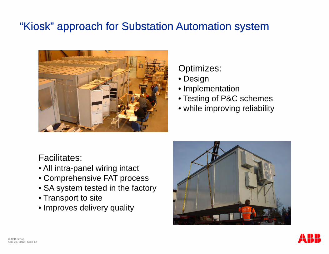
“Kiosk” approach for Substation Automation system“Kiosk” approach for Substation Automation system
O ti iOptimizes:• Design• Implementation
T ti f P&C h• Testing of P&C schemes• while improving reliability
Facilitates:Facilitates:• All intra-panel wiring intact• Comprehensive FAT process • SA system tested in the factory• SA system tested in the factory • Transport to site• Improves delivery quality
© ABB Group April 26, 2012 | Slide 12
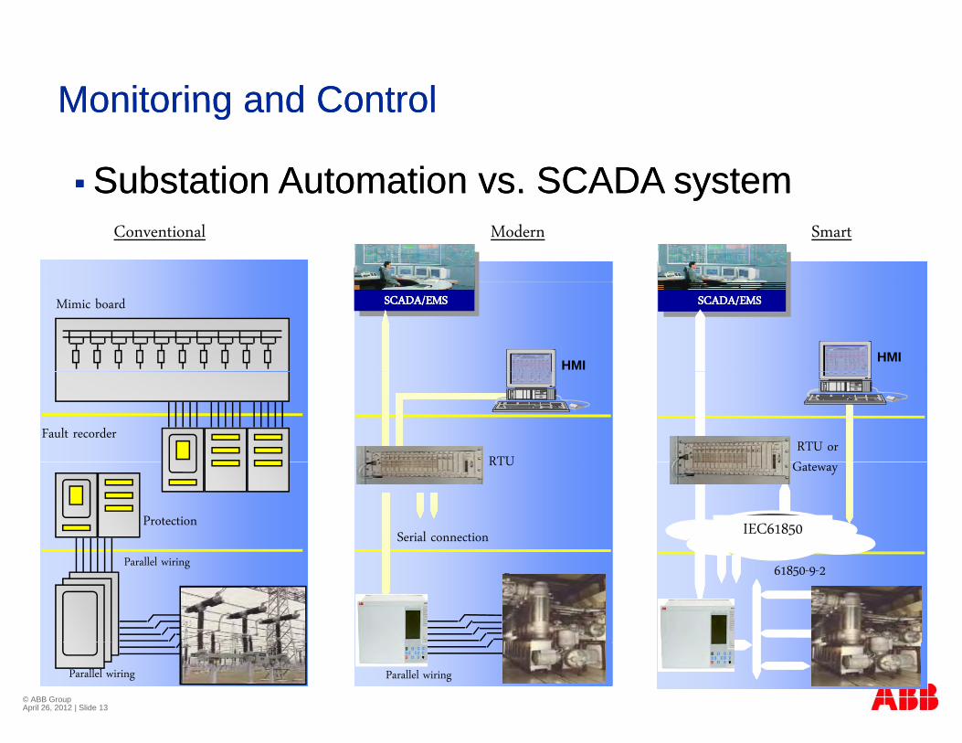
Monitoring and ControlMonitoring and Control
Substation Automation vs. SCADA systemSubstation Automation vs. SCADA system
Monitoring and ControlMonitoring and Control
Conventional Modern Smart
Substation Automation vs. SCADA systemSubstation Automation vs. SCADA system
SCADA/EMSSCADA/EMS
HMI
SCADA/EMSSCADA/EMS
HMI
Mimic board
RTURTU orG
Fault recorder
Serial connection
RTU
IEC61850
Gateway
Protection
Bay 61850-9-2Parallel wiring
© ABB Group April 26, 2012 | Slide 13
Parallel wiringParallel wiring
Alternative TechnologiesAlternative TechnologiesAlternative TechnologiesAlternative Technologies
Compact Indoor AISCompact Indoor AIS SubstationsSubstationsCompact Indoor AIS Compact Indoor AIS SubstationsSubstations
Disconnecting Circuit Breaker (DCB)Disconnecting Circuit Breaker (DCB)
GISGIS
H b id S l tiH b id S l tiHybrid SolutionsHybrid Solutions
© ABB Group April 26, 2012 | Slide 14
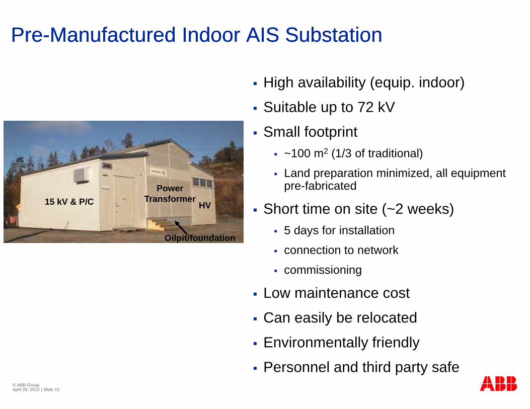
PrePre--Manufactured Manufactured Indoor AIS SubstationIndoor AIS Substation
High availability (equip. indoor)
Suitable up to 72 kV Suitable up to 72 kV
Small footprint ~100 m2 (1/3 of traditional) 100 m (1/3 of traditional)
Land preparation minimized, all equipment pre-fabricated
Sh t ti it ( 2 k )15 kV & P/CPower
TransformerHV Short time on site (~2 weeks)
5 days for installation
connection to network
5 & /C HV
Oilpit/foundation
commissioning
Low maintenance cost
Can easily be relocated
Environmentally friendly
© ABB Group April 26, 2012 | Slide 15
Personnel and third party safe
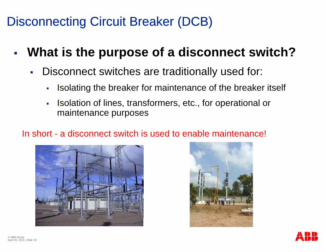
Disconnecting Circuit Breaker (DCB)Disconnecting Circuit Breaker (DCB)
What is the purpose of a disconnect switch? Disconnect switches are traditionally used for:
Isolating the breaker for maintenance of the breaker itself
Isolation of lines, transformers, etc., for operational or maintenance purposes
In short - a disconnect switch is used to enable maintenance!
© ABB Group April 26, 2012 | Slide 16
Disconnecting Circuit Breaker (DCB)Disconnecting Circuit Breaker (DCB)
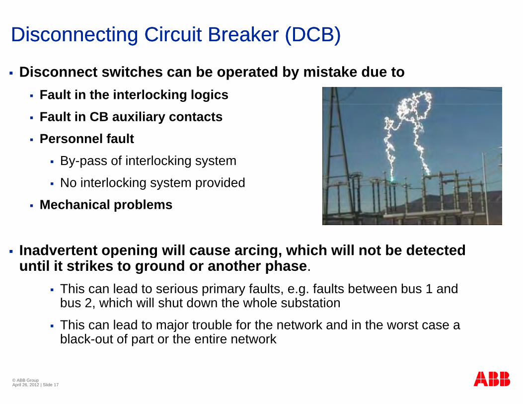
Disconnect switches can be operated by mistake due to Fault in the interlocking logics Fault in CB auxiliary contacts Personnel fault
By-pass of interlocking system
No interlocking system provided
Mechanical problems Mechanical problems
Inadvertent opening will cause arcing which will not be detected Inadvertent opening will cause arcing, which will not be detected until it strikes to ground or another phase.
This can lead to serious primary faults, e.g. faults between bus 1 and b 2 hi h ill h t d th h l b t tibus 2, which will shut down the whole substation
This can lead to major trouble for the network and in the worst case a black-out of part or the entire network
© ABB Group April 26, 2012 | Slide 17
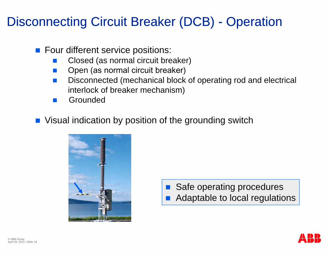
Disconnecting Circuit Breaker (DCB) Disconnecting Circuit Breaker (DCB) -- OperationOperation
Four different service positions: Closed (as normal circuit breaker) Open (as normal circuit breaker) Disconnected (mechanical block of operating rod and electrical
interlock of breaker mechanism) Grounded
Visual indication by position of the grounding switch
Safe operating procedures Safe operating procedures Adaptable to local regulations
© ABB Group April 26, 2012 | Slide 18
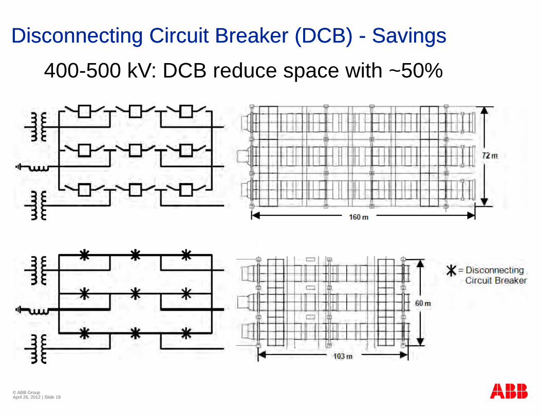
Disconnecting Circuit Breaker (DCB) Disconnecting Circuit Breaker (DCB) -- SavingsSavings
400-500 kV: DCB reduce space with ~50%
© ABB Group April 26, 2012 | Slide 19
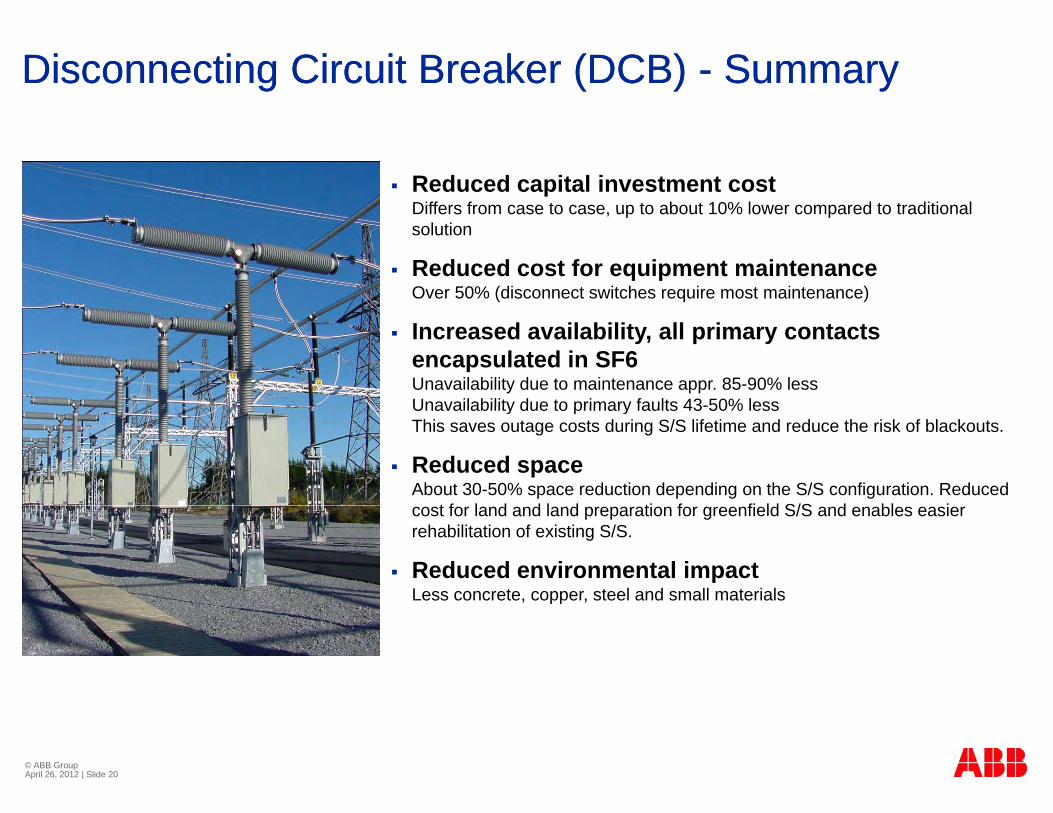
Disconnecting Circuit Breaker (DCB) Disconnecting Circuit Breaker (DCB) -- SummarySummary
Reduced capital investment costDiffers from case to case up to about 10% lower compared to traditionalDiffers from case to case, up to about 10% lower compared to traditional solution
Reduced cost for equipment maintenanceOver 50% (disconnect switches require most maintenance)
Increased availability, all primary contacts encapsulated in SF6 Unavailability due to maintenance appr. 85-90% lessUnavailability due to primary faults 43-50% lessUnavailability due to primary faults 43-50% lessThis saves outage costs during S/S lifetime and reduce the risk of blackouts.
Reduced space About 30-50% space reduction depending on the S/S configuration. Reduced
t f l d d l d ti f fi ld S/S d bl icost for land and land preparation for greenfield S/S and enables easier rehabilitation of existing S/S.
Reduced environmental impactLess concrete, copper, steel and small materials
© ABB Group April 26, 2012 | Slide 20
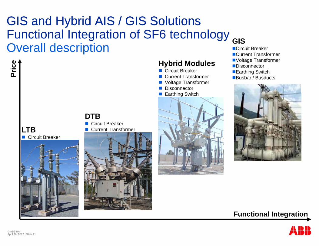
GIS and Hybrid AIS / GIS Solutions GIS and Hybrid AIS / GIS Solutions Functional Integration of SF6 technology
e Hybrid Modules
GISCircuit BreakerCurrent TransformerVoltage Transformer
Functional Integration of SF6 technologyOverall description
Pric
e Hybrid Modules Circuit Breaker Current Transformer Voltage Transformer Disconnector Earthing Switch
DisconnectorEarthing SwitchBusbar / Busducts
DTB Circuit Breaker
Earthing Switch
Circuit Breaker Current TransformerLTB
Circuit Breaker
F ti l I t ti
© ABB Inc. April 26, 2012 | Slide 21
Functional Integration
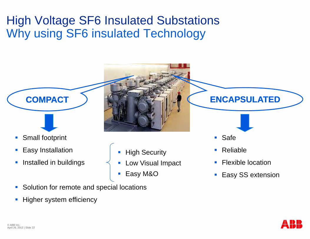
High Voltage SF6 Insulated SubstationsWhy using SF6 insulated TechnologyWhy using SF6 insulated Technology
ENCAPSULATEDENCAPSULATEDCOMPACTCOMPACT
Safe
R li bl
Small footprint
E I t ll ti Reliable
Flexible location
Easy SS extension
Easy Installation
Installed in buildings High Security Low Visual Impact Easy M&O y
Solution for remote and special locations
Higher system efficiency
© ABB Inc. April 26, 2012 | Slide 22
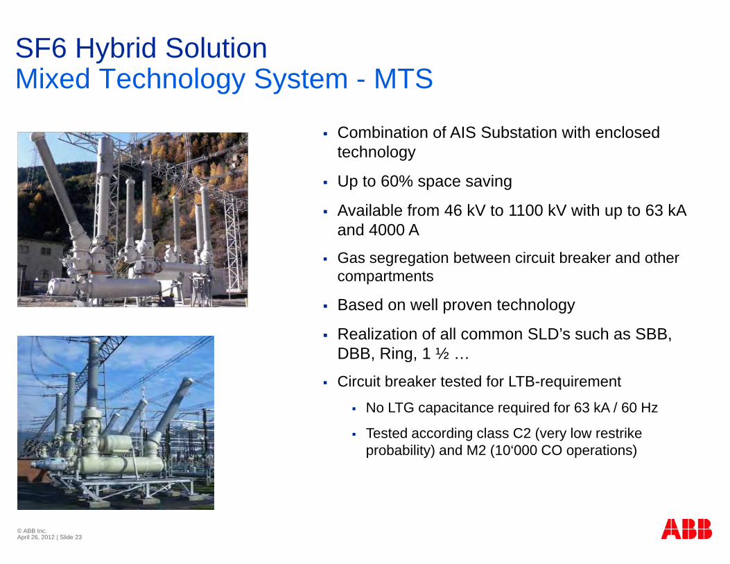
SF6 Hybrid SolutionMixed Technology System MTSMixed Technology System - MTS
Combination of AIS Substation with enclosed technology
Up to 60% space saving
Available from 46 kV to 1100 kV with up to 63 kAAvailable from 46 kV to 1100 kV with up to 63 kA and 4000 A
Gas segregation between circuit breaker and other compartmentsp
Based on well proven technology
Realization of all common SLD’s such as SBB, DBB Ring 1 ½DBB, Ring, 1 ½ …
Circuit breaker tested for LTB-requirement
No LTG capacitance required for 63 kA / 60 Hz
Tested according class C2 (very low restrike probability) and M2 (10‘000 CO operations)
© ABB Inc. April 26, 2012 | Slide 23
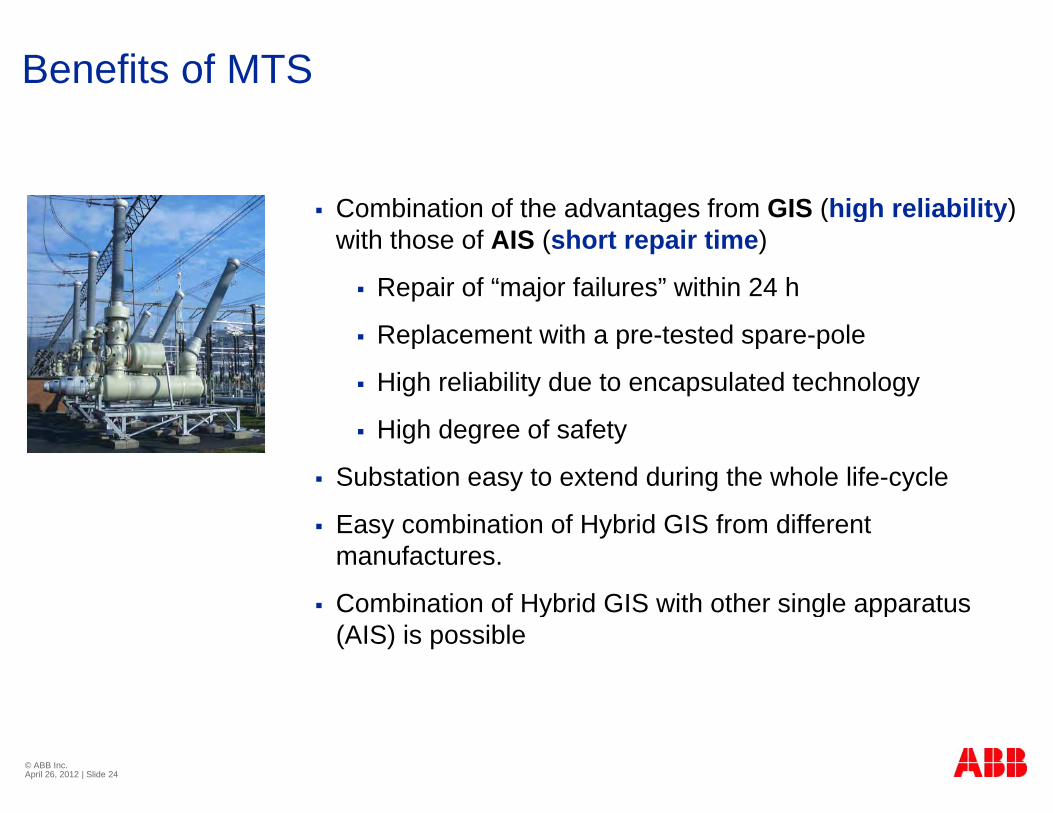
Benefits of MTS
Combination of the advantages from GIS (high reliability) Combination of the advantages from GIS (high reliability) with those of AIS (short repair time)
Repair of “major failures” within 24 h
Replacement with a pre-tested spare-pole
High reliability due to encapsulated technology
High degree of safety
Substation easy to extend during the whole life-cycle
Easy combination of Hybrid GIS from different manufactures.
Combination of Hybrid GIS with other single apparatus Combination of Hybrid GIS with other single apparatus (AIS) is possible
© ABB Inc. April 26, 2012 | Slide 24
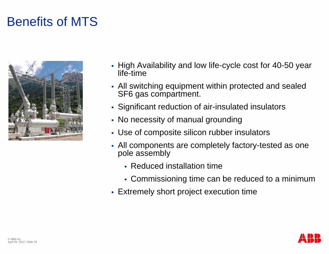
Benefits of MTS
High Availability and low life cycle cost for 40 50 year High Availability and low life-cycle cost for 40-50 year life-time
All switching equipment within protected and sealed SF6 gas compartment.SF6 gas compartment.
Significant reduction of air-insulated insulators No necessity of manual grounding Use of composite silicon rubber insulators All components are completely factory-tested as one
pole assembly Reduced installation time Commissioning time can be reduced to a minimum
E t l h t j t ti ti Extremely short project execution time
© ABB Inc. April 26, 2012 | Slide 25
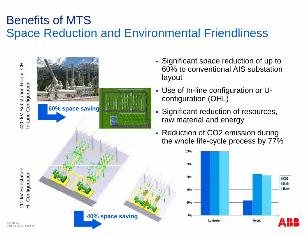
Benefits of MTSSpace Reduction and Environmental FriendlinessSpace Reduction and Environmental Friendliness
Significant space reduction of up to Significant space reduction of up to 60% to conventional AIS substation layout
Use of In line configuration or Un R
obbi
, CH
:tio
n
Use of In-line configuration or U-configuration (OHL)
Significant reduction of resources, raw material and energykV
Sub
stat
ion
ne C
onfig
ura
60% space saving
raw material and energy
Reduction of CO2 emission during the whole life-cycle process by 77%
420
kIn
-Li
atio
non 60%
80%
100%
10 k
V S
ubst
a-C
onfig
urat
io
20%
40%
60% CO2StahlBeton
© ABB Inc. April 26, 2012 | Slide 26
11 H
40% space saving 0%Luftisoliert Hybrid


![IEEE 693 Seismic Qualification of Composites for Substation ...IEEE Standard 693-1997, "IEEE Recommended Practice for Seismic Design of Substations" [1], is a major improvement in](https://img.pdfslide.us/doc/110x75/61028a6809446d71ff27f1a5/ieee-693-seismic-qualification-of-composites-for-substation-ieee-standard-693-1997.jpg)