Embed Size (px)
Citation preview
IEEE Standard for Qualifying Permanent Connections Used on Substation Grounding
Sponsored by the Substations Committee
IEEE 3 Park Avenue New York, NY 10016-5997 USA
IEEE Power and Energy Society
IEEE Std 837™-2014(Revision of
IEEE Std 837-2002)

IEEE Std 837™-2014 (Revision of
IEEE Std 837-2002)
IEEE Standard for Qualifying Permanent Connections Used on Substation Grounding
Sponsor Substations Committee of the IEEE Power and Energy Society Approved 21 August 2014 IEEE-SA Standards Board
Abstract: Direction and methods for qualifying permanent connections used for substation grounding are provided in this standard. This standard particularly addresses the connection used within the grid system, the connection used to join ground leads to the grid system, and the connection used to join the ground leads to equipment and structures. Keywords: conductor, conductor combination, connection, connection thermal capacity, control conductor, current loop cycle, equalizer, grid system, grounding, grounding connection, IEEE 837™, permanent connection
•
The Institute of Electrical and Electronics Engineers, Inc. 3 Park Avenue, New York, NY 10016-5997, USA Copyright © 2014 by The Institute of Electrical and Electronics Engineers, Inc. All rights reserved. Published 28 October 2014. Printed in the United States of America. IEEE is a registered trademark in the U.S. Patent & Trademark Office, owned by The Institute of Electrical and Electronics Engineers, Incorporated. PDF: ISBN 978-0-7381-9271-0 STD98762 Print: ISBN 978-0-7381-9272-7 STDPD98762 IEEE prohibits discrimination, harassment, and bullying. For more information, visit http://www.ieee.org/web/aboutus/whatis/policies/p9-26.html. No part of this publication may be reproduced in any form, in an electronic retrieval system or otherwise, without the prior written permission of the publisher.
Important Notices and Disclaimers Concerning IEEE Standards Documents
IEEE documents are made available for use subject to important notices and legal disclaimers. These notices and disclaimers, or a reference to this page, appear in all standards and may be found under the heading “Important Notice” or “Important Notices and Disclaimers Concerning IEEE Standards Documents.”
Notice and Disclaimer of Liability Concerning the Use of IEEE Standards Documents
IEEE Standards documents (standards, recommended practices, and guides), both full-use and trial-use, are developed within IEEE Societies and the Standards Coordinating Committees of the IEEE Standards Association (“IEEE-SA”) Standards Board. IEEE (“the Institute”) develops its standards through a consensus development process, approved by the American National Standards Institute (“ANSI”), which brings together volunteers representing varied viewpoints and interests to achieve the final product. Volunteers are not necessarily members of the Institute and participate without compensation from IEEE. While IEEE administers the process and establishes rules to promote fairness in the consensus development process, IEEE does not independently evaluate, test, or verify the accuracy of any of the information or the soundness of any judgments contained in its standards.
IEEE does not warrant or represent the accuracy or content of the material contained in its standards, and expressly disclaims all warranties (express, implied and statutory) not included in this or any other document relating to the standard, including, but not limited to, the warranties of: merchantability; fitness for a particular purpose; non-infringement; and quality, accuracy, effectiveness, currency, or completeness of material. In addition, IEEE disclaims any and all conditions relating to: results; and workmanlike effort. IEEE standards documents are supplied “AS IS” and “WITH ALL FAULTS.” Use of an IEEE standard is wholly voluntary. The existence of an IEEE standard does not imply that there are no other ways to produce, test, measure, purchase, market, or provide other goods and services related to the scope of the IEEE standard. Furthermore, the viewpoint expressed at the time a standard is approved and issued is subject to change brought about through developments in the state of the art and comments received from users of the standard.
In publishing and making its standards available, IEEE is not suggesting or rendering professional or other services for, or on behalf of, any person or entity nor is IEEE undertaking to perform any duty owed by any other person or entity to another. Any person utilizing any IEEE Standards document, should rely upon his or her own independent judgment in the exercise of reasonable care in any given circumstances or, as appropriate, seek the advice of a competent professional in determining the appropriateness of a given IEEE standard.
IN NO EVENT SHALL IEEE BE LIABLE FOR ANY DIRECT, INDIRECT, INCIDENTAL, SPECIAL, EXEMPLARY, OR CONSEQUENTIAL DAMAGES (INCLUDING, BUT NOT LIMITED TO: PROCUREMENT OF SUBSTITUTE GOODS OR SERVICES; LOSS OF USE, DATA, OR PROFITS; OR BUSINESS INTERRUPTION) HOWEVER CAUSED AND ON ANY THEORY OF LIABILITY, WHETHER IN CONTRACT, STRICT LIABILITY, OR TORT (INCLUDING NEGLIGENCE OR OTHERWISE) ARISING IN ANY WAY OUT OF THE PUBLICATION, USE OF, OR RELIANCE UPON ANY STANDARD, EVEN IF ADVISED OF THE POSSIBILITY OF SUCH DAMAGE AND REGARDLESS OF WHETHER SUCH DAMAGE WAS FORESEEABLE.
Translations
The IEEE consensus development process involves the review of documents in English only. In the event that an IEEE standard is translated, only the English version published by IEEE should be considered the approved IEEE standard.
Official statements
A statement, written or oral, that is not processed in accordance with the IEEE-SA Standards Board Operations Manual shall not be considered or inferred to be the official position of IEEE or any of its committees and shall not be considered to be, or be relied upon as, a formal position of IEEE. At lectures, symposia, seminars, or educational courses, an individual presenting information on IEEE standards shall make it clear that his or her views should be considered the personal views of that individual rather than the formal position of IEEE.
Comments on standards
Comments for revision of IEEE Standards documents are welcome from any interested party, regardless of membership affiliation with IEEE. However, IEEE does not provide consulting information or advice pertaining to IEEE Standards documents. Suggestions for changes in documents should be in the form of a proposed change of text, together with appropriate supporting comments. Since IEEE standards represent a consensus of concerned interests, it is important that any responses to comments and questions also receive the concurrence of a balance of interests. For this reason, IEEE and the members of its societies and Standards Coordinating Committees are not able to provide an instant response to comments or questions except in those cases where the matter has previously been addressed. For the same reason, IEEE does not respond to interpretation requests. Any person who would like to participate in revisions to an IEEE standard is welcome to join the relevant IEEE working group.
Comments on standards should be submitted to the following address:
Secretary, IEEE-SA Standards Board 445 Hoes Lane Piscataway, NJ 08854 USA
Laws and regulations
Users of IEEE Standards documents should consult all applicable laws and regulations. Compliance with the provisions of any IEEE Standards document does not imply compliance to any applicable regulatory requirements. Implementers of the standard are responsible for observing or referring to the applicable regulatory requirements. IEEE does not, by the publication of its standards, intend to urge action that is not in compliance with applicable laws, and these documents may not be construed as doing so.
Copyrights
IEEE draft and approved standards are copyrighted by IEEE under U.S. and international copyright laws. They are made available by IEEE and are adopted for a wide variety of both public and private uses. These include both use, by reference, in laws and regulations, and use in private self-regulation, standardization, and the promotion of engineering practices and methods. By making these documents available for use and adoption by public authorities and private users, IEEE does not waive any rights in copyright to the documents.
Photocopies
Subject to payment of the appropriate fee, IEEE will grant users a limited, non-exclusive license to photocopy portions of any individual standard for company or organizational internal use or individual, non-commercial use only. To arrange for payment of licensing fees, please contact Copyright Clearance Center, Customer Service, 222 Rosewood Drive, Danvers, MA 01923 USA; +1 978 750 8400. Permission to photocopy portions of any individual standard for educational classroom use can also be obtained through the Copyright Clearance Center.
Updating of IEEE Standards documents
Users of IEEE Standards documents should be aware that these documents may be superseded at any time by the issuance of new editions or may be amended from time to time through the issuance of amendments, corrigenda, or errata. An official IEEE document at any point in time consists of the current edition of the document together with any amendments, corrigenda, or errata then in effect.
Every IEEE standard is subjected to review at least every ten years. When a document is more than ten years old and has not undergone a revision process, it is reasonable to conclude that its contents, although still of some value, do not wholly reflect the present state of the art. Users are cautioned to check to determine that they have the latest edition of any IEEE standard.
In order to determine whether a given document is the current edition and whether it has been amended through the issuance of amendments, corrigenda, or errata, visit the IEEE-SA Website at http://ieeexplore.ieee.org/xpl/standards.jsp or contact IEEE at the address listed previously. For more information about the IEEE SA or IEEE’s standards development process, visit the IEEE-SA Website at http://standards.ieee.org.
Errata
Errata, if any, for all IEEE standards can be accessed on the IEEE-SA Website at the following URL: http://standards.ieee.org/findstds/errata/index.html. Users are encouraged to check this URL for errata periodically.
Patents
Attention is called to the possibility that implementation of this standard may require use of subject matter covered by patent rights. By publication of this standard, no position is taken by the IEEE with respect to the existence or validity of any patent rights in connection therewith. If a patent holder or patent applicant has filed a statement of assurance via an Accepted Letter of Assurance, then the statement is listed on the IEEE-SA Website at http://standards.ieee.org/about/sasb/patcom/patents.html. Letters of Assurance may indicate whether the Submitter is willing or unwilling to grant licenses under patent rights without compensation or under reasonable rates, with reasonable terms and conditions that are demonstrably free of any unfair discrimination to applicants desiring to obtain such licenses.
Essential Patent Claims may exist for which a Letter of Assurance has not been received. The IEEE is not responsible for identifying Essential Patent Claims for which a license may be required, for conducting inquiries into the legal validity or scope of Patents Claims, or determining whether any licensing terms or conditions provided in connection with submission of a Letter of Assurance, if any, or in any licensing agreements are reasonable or non-discriminatory. Users of this standard are expressly advised that determination of the validity of any patent rights, and the risk of infringement of such rights, is entirely their own responsibility. Further information may be obtained from the IEEE Standards Association.

Participants
At the time this IEEE standard was completed, the E9 Working Group had the following membership:
David Kelly, Chair Brian Story, Vice Chair
Michael Rzasa, Secretary Jesse Rorabaugh, Technical Writer
Hanna Abdallah Stan Arnot Radoslav Barac Thomas Barnes Hassein Bashirian Romulus Berzescu Bryan Beske Dale Boling Bill Carmen K. S. Chan Koushik Chanda Carson Day
Dennis DeCosta William K. Dick Marcia Eblen David Garrett Joseph Gravelle Steve Greenfield Martin Havelka Robert Hobbs Richard Keil Reginaldo Maniego Jon Martin Saki Meliopoulos Carl Moller
Roger Montambo William Morrissey Mike Noori Shashi Patel William Sheh Douglas Smith Gregory J. Steinman Curtis Stidham Yance Syarif Logan Trombley Keith Wallace Alexander Wong
The following members of the individual balloting committee voted on this standard. Balloters may have voted for approval, disapproval, or abstention.
William Ackerman Ali Al Awazi Stan Arnot Thomas Barnes George Becker W. J. (Bill) Bergman Bryan Beske Steven Bezner Dale Boling Chris Brooks Kevin Buhle William Byrd James Cain Thomas Callsen Michael Champagne Koushik Chanda Robert Christman Franco D’Alessandro Dennis DeCosta David E. De Luca Gary Donner Michael Dood Randall Dotson Keith Flowers Paul Forquer Marcel Fortin David Garrett George Gela Jalal Gohari Edwin Goodwin Joseph Gravelle Steven Greenfield
Randall Groves Ajit Gwal Charles Haahr Thomas Harger David Harris Martin Havelka Lee Herron Gary Heuston Robert Hobbs Gary Hoffman John Kay David Kelley Gael Kennedy Yuri Khersonsky Hermann Koch Jim Kulchisky Saumen Kundu Chung-Yiu Lam Thomas La Rose Michael Lauxman Henri Lemeilleur Greg Luri Jon Martin Andrew McElroy Shawn McGann John Miller Daleep Mohla Carl Moller Georges Montillet Jerry Murphy Dennis Neitzel Michael Newman
Joe Nims Robert Nowell Lorraine Padden Shashi Patel Percy Pool Thomas Proios Michael Roberts Jesse Rorabaugh Thomas Rozek Michael Rzasa Bartien Sayogo Dennis Schlender Devki Sharma William Sheh Douglas Smith James Smith Jerry Smith John Spare Ryan Stargel Gregory J. Steinman Curtis Stidham Gary Stoedter Brian Story David Tepen Malcolm Thaden John Vergis Jane Verner Donald Wengerter Kenneth White Alexander Wong Roland Youngberg Jian Yu
Copyright © 2014 IEEE. All rights reserved.
vi
When the IEEE-SA Standards Board approved this standard on 21 August 2014, it had the following membership:
John Kulick, Chair Jon Walter Rosdahl, Vice Chair Richard H. Hulett, Past Chair
Konstantinos Karachalios, Secretary
Peter Balma Farooq Bari Ted Burse Clint Chaplin Stephen Dukes Jean-Philippe Faure Gary Hoffman
Michael Janezic Jeffrey Katz Joseph L. Koepfinger* David J. Law Hung Ling Oleg Logvinov T. W. Olsen Glenn Parsons
Ron Petersen Adrian Stephens Peter Sutherland Yatin Trivedi Phil Winston Don Wright Yu Yuan
*Member Emeritus
Also included are the following nonvoting IEEE-SA Standards Board liaisons:
Richard DeBlasio, DOE Representative Michael Janezic, NIST Representative
Catherine Berger
IEEE-SA Content Publishing
Erin Spiewak IEEE-SA Technical Community Programs
Copyright © 2014 IEEE. All rights reserved.
vii
Introduction
This introduction is not part of IEEE Std 837-2014, IEEE Standard for Qualifying Permanent Connections Used on Substation Grounding.
Working Group E9 of the IEEE PES Substations Committee began updating the standard in 2008. This standard has been updated to fulfill a need for standardization of terminology and test requirements for permanent grounding connections. The most significant changes were made to the EMF test criteria that address the connections to above-grade rigid structures and equipment ground pads. Many types of connections are available that may be used as permanent grounding connections even though they were designed for use as power connections. This standard provides a meaningful reproducible test program that will enable connection manufacturers to qualify their products as permanent grounding connections. The users can then be reasonably assured that the qualified permanent grounding connection will be capable of performing satisfactorily over the lifetime of the installation. This standard addresses the parameters for testing grounding connections on copper, steel, copper-bonded steel, copper-clad steel, galvanized steel, and stainless steel.
Copyright © 2014 IEEE. All rights reserved.
viii
Contents
1. Overview .................................................................................................................................................... 1 1.1 Scope ................................................................................................................................................... 1 1.2 Purpose ................................................................................................................................................ 1
2. Normative references .................................................................................................................................. 2
3. Definitions .................................................................................................................................................. 3
4. Qualification tests ....................................................................................................................................... 3
5. Performance criteria ................................................................................................................................... 4 5.1 General ................................................................................................................................................ 4 5.2 Mechanical tests .................................................................................................................................. 4 5.3 Sequential tests .................................................................................................................................... 5
6. Test procedures ........................................................................................................................................... 9 6.1 General ................................................................................................................................................ 9 6.2 Mechanical test samples ...................................................................................................................... 9 6.3 Sequential test samples ........................................................................................................................ 9 6.4 Connections description ....................................................................................................................... 9 6.5 Test conductors .................................................................................................................................... 9 6.6 Test assembly methods ........................................................................................................................ 9 6.7 Connection preparation ........................................................................................................................ 9 6.8 Installation ......................................................................................................................................... 10
7. Mechanical test ......................................................................................................................................... 10 7.1 General .............................................................................................................................................. 10 7.2 Electromagnetic force (EMF) test ...................................................................................................... 10
8. Current-temperature cycling test .............................................................................................................. 17 8.1 General .............................................................................................................................................. 17 8.2 Current-temperature cycling test ....................................................................................................... 17 8.3 Ambient conditions ............................................................................................................................ 18 8.4 Control conductor .............................................................................................................................. 18 8.5 Current cycling .................................................................................................................................. 18 8.6 Current cycling loop configuration .................................................................................................... 20 8.7 Current cycling measurements........................................................................................................... 21
9. Freeze-thaw test ........................................................................................................................................ 22 9.1 General .............................................................................................................................................. 22 9.2 Freeze-thaw test ................................................................................................................................. 22 9.3 Freeze-thaw test samples and their configuration .............................................................................. 22 9.4 Freeze-thaw test equipment ............................................................................................................... 22 9.5 Freeze-thaw test cycle........................................................................................................................ 22
10. Corrosion tests ........................................................................................................................................ 23 10.1 General ............................................................................................................................................ 23 10.2 Corrosion test-salt spray .................................................................................................................. 23 10.3 Corrosion test-acid (HNO3) ............................................................................................................. 24
11. Fault-current test ..................................................................................................................................... 26
Copyright © 2014 IEEE. All rights reserved.
ix
11.1 General ............................................................................................................................................ 26 11.2 Fault-current test .............................................................................................................................. 26 11.3 Fault-current test samples ................................................................................................................ 26 11.4 Fault-current test configuration ....................................................................................................... 26 11.5 Fault-current test duration ................................................................................................................ 26 11.6 Fault-current test current .................................................................................................................. 26 11.7 Fault-current number of surges ........................................................................................................ 27 11.8 Pass/Fail fault-current test evaluation .............................................................................................. 27
Annex A (informative) Bibliography ........................................................................................................... 28
Annex B (informative) Nitric-acid dilution .................................................................................................. 29
Annex C (normative) Conductive ampacity calculation ............................................................................... 30
Annex D (informative) Test sequencing ....................................................................................................... 40
Annex E (informative) Effects of asymmetrical currents and multiple conductor test requirements ........... 42
Copyright © 2014 IEEE. All rights reserved.
x
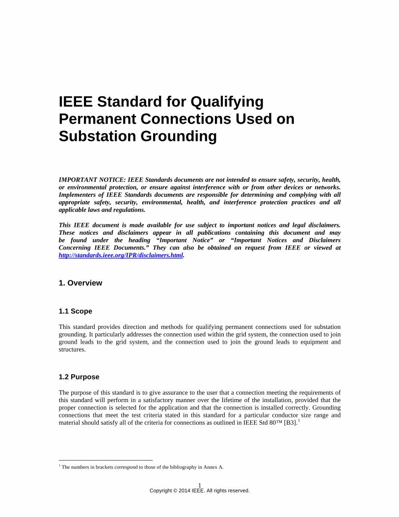
IEEE Standard for Qualifying Permanent Connections Used on Substation Grounding
IMPORTANT NOTICE: IEEE Standards documents are not intended to ensure safety, security, health, or environmental protection, or ensure against interference with or from other devices or networks. Implementers of IEEE Standards documents are responsible for determining and complying with all appropriate safety, security, environmental, health, and interference protection practices and all applicable laws and regulations.
This IEEE document is made available for use subject to important notices and legal disclaimers. These notices and disclaimers appear in all publications containing this document and may be found under the heading “Important Notice” or “Important Notices and Disclaimers Concerning IEEE Documents.” They can also be obtained on request from IEEE or viewed at http://standards.ieee.org/IPR/disclaimers.html.
1. Overview
1.1 Scope
This standard provides direction and methods for qualifying permanent connections used for substation grounding. It particularly addresses the connection used within the grid system, the connection used to join ground leads to the grid system, and the connection used to join the ground leads to equipment and structures.
1.2 Purpose
The purpose of this standard is to give assurance to the user that a connection meeting the requirements of this standard will perform in a satisfactory manner over the lifetime of the installation, provided that the proper connection is selected for the application and that the connection is installed correctly. Grounding connections that meet the test criteria stated in this standard for a particular conductor size range and material should satisfy all of the criteria for connections as outlined in IEEE Std 80™ [B3].1
1 The numbers in brackets correspond to those of the bibliography in Annex A.
Copyright © 2014 IEEE. All rights reserved.
1
IEEE Std 837-2014 IEEE Standard for Qualifying Permanent Connections Used on Substation Grounding
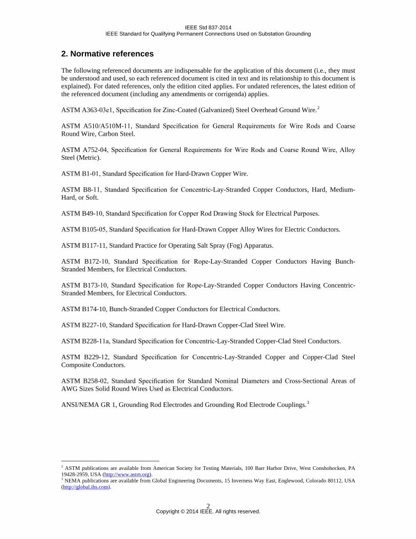
2. Normative references
The following referenced documents are indispensable for the application of this document (i.e., they must be understood and used, so each referenced document is cited in text and its relationship to this document is explained). For dated references, only the edition cited applies. For undated references, the latest edition of the referenced document (including any amendments or corrigenda) applies.
ASTM A363-03e1, Specification for Zinc-Coated (Galvanized) Steel Overhead Ground Wire.2
ASTM A510/A510M-11, Standard Specification for General Requirements for Wire Rods and Coarse Round Wire, Carbon Steel.
ASTM A752-04, Specification for General Requirements for Wire Rods and Coarse Round Wire, Alloy Steel (Metric).
ASTM B1-01, Standard Specification for Hard-Drawn Copper Wire.
ASTM B8-11, Standard Specification for Concentric-Lay-Stranded Copper Conductors, Hard, Medium-Hard, or Soft.
ASTM B49-10, Standard Specification for Copper Rod Drawing Stock for Electrical Purposes.
ASTM B105-05, Standard Specification for Hard-Drawn Copper Alloy Wires for Electric Conductors.
ASTM B117-11, Standard Practice for Operating Salt Spray (Fog) Apparatus.
ASTM B172-10, Standard Specification for Rope-Lay-Stranded Copper Conductors Having Bunch-Stranded Members, for Electrical Conductors.
ASTM B173-10, Standard Specification for Rope-Lay-Stranded Copper Conductors Having Concentric-Stranded Members, for Electrical Conductors.
ASTM B174-10, Bunch-Stranded Copper Conductors for Electrical Conductors.
ASTM B227-10, Standard Specification for Hard-Drawn Copper-Clad Steel Wire.
ASTM B228-11a, Standard Specification for Concentric-Lay-Stranded Copper-Clad Steel Conductors.
ASTM B229-12, Standard Specification for Concentric-Lay-Stranded Copper and Copper-Clad Steel Composite Conductors.
ASTM B258-02, Standard Specification for Standard Nominal Diameters and Cross-Sectional Areas of AWG Sizes Solid Round Wires Used as Electrical Conductors.
ANSI/NEMA GR 1, Grounding Rod Electrodes and Grounding Rod Electrode Couplings.3
2 ASTM publications are available from American Society for Testing Materials, 100 Barr Harbor Drive, West Conshohocken, PA 19428-2959, USA (http://www.astm.org). 3 NEMA publications are available from Global Engineering Documents, 15 Inverness Way East, Englewood, Colorado 80112, USA (http://global.ihs.com).
Copyright © 2014 IEEE. All rights reserved.
2
IEEE Std 837-2014 IEEE Standard for Qualifying Permanent Connections Used on Substation Grounding
3. Definitions
For the purposes of this document, the following terms and definitions apply. The IEEE Standards Dictionary Online should be consulted for terms not defined in this clause.4
conductor: A metallic substance that allows a current of electricity to pass continuously along it. As used in this standard, a conductor includes cable (wire), rods (electrodes), and metallic structures.
conductor combination: The various conductors that are joined by a connection.
connection: A metallic device of suitable electrical conductance and mechanical strength used to join conductors.
connection thermal capacity: The ability of a connection to withstand the amount of current required to produce a specified temperature on the control conductor without increasing the resistance of the connection beyond that specified in this standard.
control conductor: The conductor that is utilized to measure equivalent changes in temperature, size, etc., that are occurring in at least one of the conductors joined by the connection under test.
current loop cycle: The combination of conductors and connections that carries the current of the circuit under test.
equalizer: A device to provide equipotential planes for resistance measurements.
grid system: A system consisting of interconnected bare conductors buried in the earth or in concrete to provide a common ground for electrical devices and metallic structures.
permanent connection: A grounding connection that will retain its electrical and mechanical integrity for the design life of the conductor within limits established by this standard.
4. Qualification tests
For qualification test sequence, refer to Annex D. Qualifications tests shall be performed for each family of connections, for example: (cable to cable straight connection, tap connection, cross connection), (cable to ground rod connection), (cable to lug connection), and (cable to structure connection).
Qualification tests shall be performed for each style of connection. For example, crimped lug connections and lugs using bolted pressure plates to secure the cable are considered different styles. Therefore, both connectors are required to be tested to qualify the styles. Other examples of different connector design styles include cable to cable and cable-cross design styles. Within a family of connectors, more robust connectors need not be tested. For example, bolted pressure plate lugs using four (4) bolts need not be tested if two (2) bolts lugs have been tested successfully for the same size. Similarly, for a family of connectors tested for 4/0 AWG Copper or 19/#8 Copper Clad Steel (at 90% of fusing test current for the EMF test); smaller sizes may be qualified by passing only the initial resistance tests from 5.3.2.1. For these smaller sizes, no other tests are required. However, connections for larger conductors specified in footnote b of Table 3 shall be tested for each size connection.
When a connector design allows for a range of conductors, each of the tests outlined in Table 1 and Annex D must be performed on the “largest to largest” combination as well as the “largest to smallest”
4IEEE Standards Dictionary Online subscription is available at: http://www.ieee.org/portal/innovate/products/standard/standards_dictionary.html.
Copyright © 2014 IEEE. All rights reserved.
3
IEEE Std 837-2014 IEEE Standard for Qualifying Permanent Connections Used on Substation Grounding
combination. Connectors shall be tested for all materials for which they are intended to be qualified per this standard. For example copper-clad steel conductors and connectors that are designed to be used on copper-bonded steel ground rods must be qualified by all of the tests in this standard. Several test parameters for connectors for use on 40% copper-clad steel conductors and copper-bonded steel ground rods are based upon electrical equivalency of copper conductors as listed in Table 5. The test parameters for conductors and ground rods not listed in Table 3 shall be calculated as per Annex C. A listing of the tests to be performed for all types of connections is given in Table 1. The connections shall be tested individually and sequentially, as shown in Table 1. If during the testing, one of the four test samples fails, the testing must be discontinued. A group of four new samples from a different lot can then be retested. If one of the samples from the new group fails, the connector design does not meet the requirements of this standard and is considered as failed. This is applicable to all of the tests detailed in Table 1.
Table 1 —Qualification test sequence and quantitiesa
Test Clause Number of samples per testb Mechanical Tests —Electromagnetic Force Test
7.2 4
Sequential test groups —Current-temperature cycling —Freeze-thaw —Corrosion—salt spray, acid —Fault current
------ 8.1 – 8.7 9.1 – 9.5
10.1 – 10.3 11.1 – 11.8
4 for salt spray sequence
4 for acid sequence
a See Annex D for additional information. b These are the number of connection samples of each connection design and conductor combination tested.
5. Performance criteria
5.1 General
When installed and tested in accordance with this standard, all connections shall conform to the performance criteria given in 5.2 and 5.3.
5.2 Mechanical tests
5.2.1 Electromagnetic force (EMF) withstand criteria
When tested in accordance with 7.2, the connector shall remain intact. The maximum allowable movement of the test conductor at each location shown in Figure 1 after two EMF surges shall not exceed either 10 mm or the outer diameter of the conductor, whichever is less (note in Figure 1, “X” illustrates what is meant by movement).
Copyright © 2014 IEEE. All rights reserved.
4

IEEE Std 837-2014 IEEE Standard for Qualifying Permanent Connections Used on Substation Grounding
Figure 1 —Movement illustration
5.3 Sequential tests
5.3.1 Temperature criteria
The temperature of the connections tested in accordance with Clause 8 shall not exceed the temperature of the control conductor.
5.3.2 Resistance criteria
The resistance of the connection, calculated per 5.3.2.1 and tested in accordance with Clause 8, Clause 9, 10.1, 10.2-2, and Clause 11 for the salt spray sequence, and Clause 8, Clause 9, 10.1, 10.3, and Clause 11 for the acid sequence, shall not be greater than the specified values when compared to the initial resistance value. Resistance measurements shall be taken in accordance with 5.3.2.3. The resistance values shall be corrected to 20 °C.
5.3.2.1 Initial resistance criteria
Resistance measurements shall be taken at the start of the testing and at intervals during the testing as indi-cated. The ambient temperature shall be recorded at the time of each set of resistance measurements. The initial resistance for the sample connection under test is determined as follows within the next seven (7) steps:
NEW INTERFACE
ORIGINAL SCRIBE MARK X
X
Copyright © 2014 IEEE. All rights reserved.
5
IEEE Std 837-2014 IEEE Standard for Qualifying Permanent Connections Used on Substation Grounding
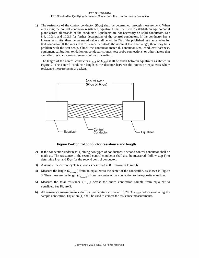
1) The resistance of the control conductor (RCC1) shall be determined through measurement. When measuring the control conductor resistance, equalizers shall be used to establish an equipotential plane across all strands of the conductor. Equalizers are not necessary on solid conductors. See 8.4, 10.3.4, and 10.3.6 for further descriptions of the control conductors. If the conductor has a known resistivity, then the measured value shall be within 5% of the published resistance value for that conductor. If the measured resistance is outside the nominal tolerance range, there may be a problem with the test setup. Check the conductor material, conductor size, conductor hardness, equipment calibration, oxidation on conductor strands, test probe connections, or other factors that can affect resistance measurements before proceeding.
The length of the control conductor (LCC1 or LCC2) shall be taken between equalizers as shown in Figure 2. The control conductor length is the distance between the points on equalizers where resistance measurements are taken.
Figure 2 —Control conductor resistance and length
2) If the connection under test is joining two types of conductors, a second control conductor shall be made up. The resistance of the second control conductor shall also be measured. Follow step 1) to determine LCC2 and RCC2 for the second control conductor.
3) Assemble the current cycle test loop as described in 8.6 shown in Figure 6.
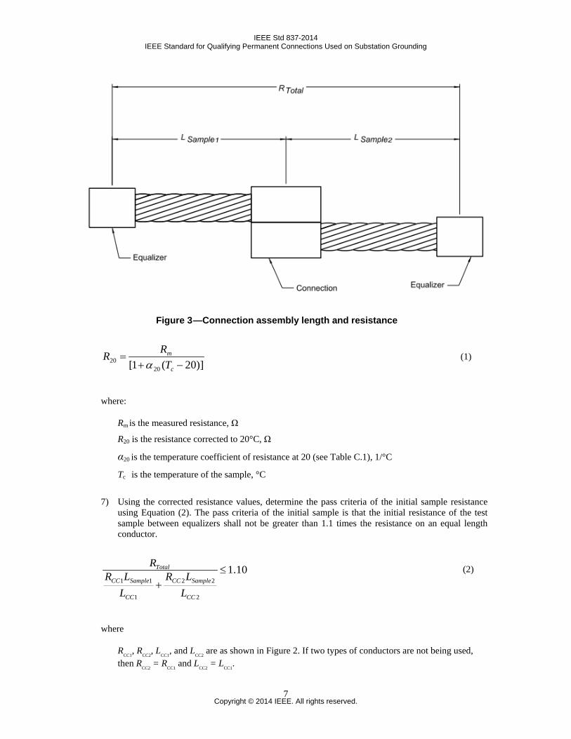
4) Measure the length (LSample1) from an equalizer to the center of the connection, as shown in Figure 3. Then measure the length (LSample2) from the center of the connection to the opposite equalizer.
5) Measure the total resistance (RTotal) across the entire connection sample from equalizer to equalizer. See Figure 3.
6) All resistance measurements shall be temperature corrected to 20 °C (R20) before evaluating the sample connection. Equation (1) shall be used to correct the resistance measurements.
LCC1 or LCC2 (RCC1 or RCC2)
Copyright © 2014 IEEE. All rights reserved.
6
IEEE Std 837-2014 IEEE Standard for Qualifying Permanent Connections Used on Substation Grounding
Figure 3 —Connection assembly length and resistance
)]20(1[ 2020 −+=
c
m
TRR
α (1)
where:
Rm is the measured resistance, Ω
R20 is the resistance corrected to 20°C, Ω
α20 is the temperature coefficient of resistance at 20 (see Table C.1), 1/°C
Tc is the temperature of the sample, °C
7) Using the corrected resistance values, determine the pass criteria of the initial sample resistance using Equation (2). The pass criteria of the initial sample is that the initial resistance of the test sample between equalizers shall not be greater than 1.1 times the resistance on an equal length conductor.
10.1
2
22
1
11≤
+CC
SampleCC
CC
SampleCC
Total
LLR
LLR
R (2)
where
RCC1
, RCC2
, LCC1
, and LCC2
are as shown in Figure 2. If two types of conductors are not being used, then R
CC2 = R
CC1 and L
CC2 = L
CC1.
Copyright © 2014 IEEE. All rights reserved.
7
IEEE Std 837-2014 IEEE Standard for Qualifying Permanent Connections Used on Substation Grounding
5.3.2.2 Final resistance criteria (after sequential tests)
Final resistance measurements for each sample (RFinal
) shall be measured as described in 5.3.2.3 and depicted in Figure 3 for total resistance (R
Total), along with the ambient temperature as required in 5.3.2.4.
Final resistance measurements shall be corrected to 20 °C using Equation (1). Pass criteria for final resistance results shall be such that the corrected value of (R
Final) does not exceed 1.5 times the initial (R
Total)
value for each sample tested.
5.3.2.2.1 Criteria for salt spray corrosion test sequences
A sample shall be considered as passing when the final resistance (RFinal
) does not exceed 1.5 times the initial total resistance (R
Total) value.
5.3.2.2.2 Criteria for acid corrosion test sequences
A sample shall be considered as passing when the final resistance (RFinal) does not exceed 1.5 times the initial total resistance (RTotal) value. Alternate pass criteria: A sample shall be considered as passing when the final resistance (RFinal) does not exceed 1.5 times the total resistance (RTotal) value of the control conductor, which has been subjected to the same acid test. The value for final resistance (RFinal) shall be calculated from Equation (2) using values of RCC1, RCC2, LCC1, and LCC2 taken from the control conductors, which were subjected to the same acid test as the actual test samples.
5.3.2.3 Resistance measurements
Resistance measurements shall be made when the conductor temperature is at ambient temperature. The measurements shall be made across the control conductor and across each connection between potential points located in the center of the equalizers adjacent to the connection or at the equivalent points on a solid conductor. For these measurements, a current of a sufficiently low magnitude shall be used to avoid appre-ciable heating.
Resistance measurements shall be taken prior to each test within a sequential test group. For sequential test samples, final resistance measurements shall be taken after the fault-current test in Clause 11.
5.3.2.4 Temperature correction
Ambient temperature shall be recorded concurrently with each set of resistance measurements, and the resistance shall be corrected to 20 °C. The corrected resistance shall be used in evaluating the performance of the connection.
5.3.3 Fault-current criteria
Connections tested in accordance with Clause 11 shall not melt, separate from, or move in relation to the pre-marked conductor and must meet the resistance criteria set in 5.3.2.2. The conductor shall not fuse within 50 mm of either end of a connection under test.
Copyright © 2014 IEEE. All rights reserved.
8
IEEE Std 837-2014 IEEE Standard for Qualifying Permanent Connections Used on Substation Grounding
6. Test procedures
6.1 General
Mechanical tests are to be conducted on new connections for electromagnetic withstand strength of the connection in accordance with Clause 7.
6.2 Mechanical test samples
The samples subjected to mechanical test shall not be used for the sequential tests. Samples are described in 7.2.1 and 7.2.2.
6.3 Sequential test samples
Current-temperature cycling, freeze-thaw, corrosion, and fault-current tests are to be conducted sequentially. Use the same samples for all tests conducted in accordance with Clause 8 through Clause 11. Sample length is described in 8.2.4. Separate sample sets are used for the sequential salt spray and sequential acid tests.
6.4 Connections description
A description adequate for complete identification of the test connections shall be included in the test report. This description shall include (and not limited to) manufacturer, model number, and the description of the type of connector.
6.5 Test conductors
The conductors shall conform to the following applicable standards: ASTM A363-03e1, ASTM A510 / A510M-11, ASTM A752-04, ASTM B1-01, ASTM B8-11, ASTM B49-10, ASTM B105-05, ASTM B117-11, ASTM B172-10, ASTM B173-10, ASTM B174-10, ASTM B227-10, ASTM B228-11a, ASTM B229-12, ASTM B258-02, ANSI/NEMA GR 1.
6.6 Test assembly methods
All assembly details not specifically defined in this standard shall be completely described in the test report.
6.7 Connection preparation
Connections shall be prepared in accordance with the manufacturer’s recommendations for field installation.
Copyright © 2014 IEEE. All rights reserved.
9
IEEE Std 837-2014 IEEE Standard for Qualifying Permanent Connections Used on Substation Grounding
6.8 Installation
The method of installation and the installation tooling shall be in accordance with the manufacturer’s recommendations for field installation. Unless otherwise specified in the manufacturer’s instructions, the connections shall be installed in accordance with Figure 4 for the mechanical tests and Figure 6 for the sequential test.
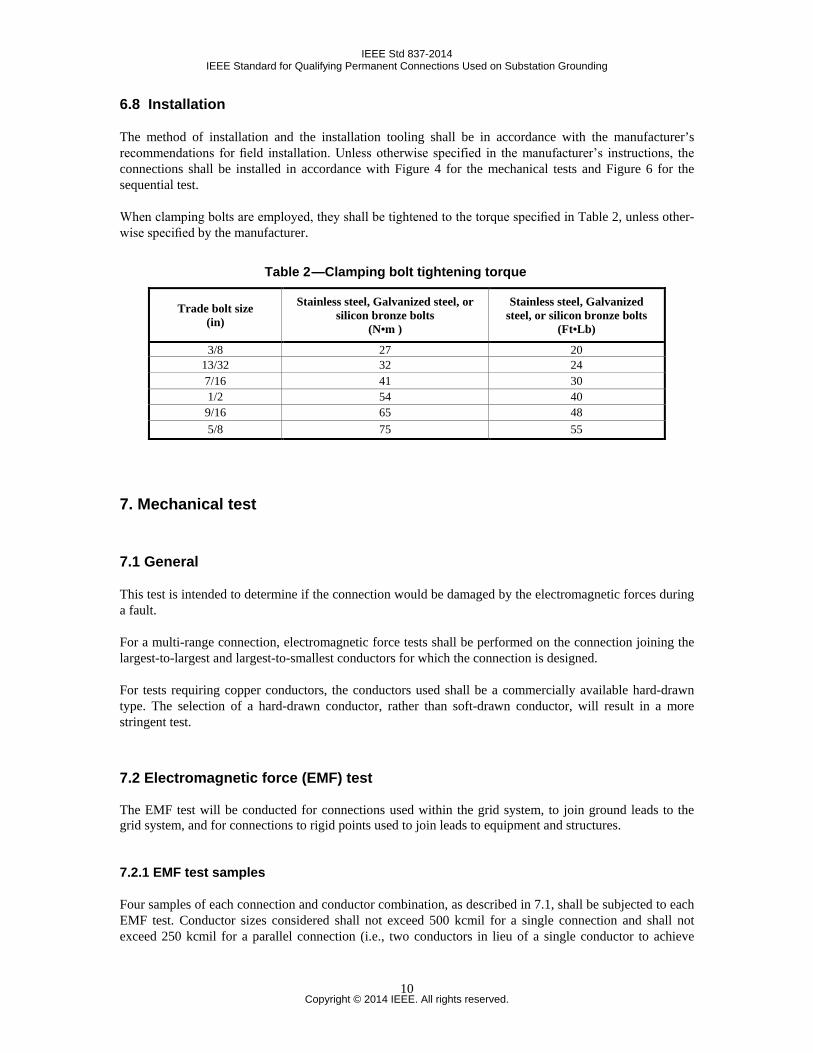
When clamping bolts are employed, they shall be tightened to the torque specified in Table 2, unless other-wise specified by the manufacturer.
Table 2 —Clamping bolt tightening torque
7. Mechanical test
7.1 General
This test is intended to determine if the connection would be damaged by the electromagnetic forces during a fault.
For a multi-range connection, electromagnetic force tests shall be performed on the connection joining the largest-to-largest and largest-to-smallest conductors for which the connection is designed.
For tests requiring copper conductors, the conductors used shall be a commercially available hard-drawn type. The selection of a hard-drawn conductor, rather than soft-drawn conductor, will result in a more stringent test.
7.2 Electromagnetic force (EMF) test
The EMF test will be conducted for connections used within the grid system, to join ground leads to the grid system, and for connections to rigid points used to join leads to equipment and structures.
7.2.1 EMF test samples
Four samples of each connection and conductor combination, as described in 7.1, shall be subjected to each EMF test. Conductor sizes considered shall not exceed 500 kcmil for a single connection and shall not exceed 250 kcmil for a parallel connection (i.e., two conductors in lieu of a single conductor to achieve
Trade bolt size (in)
Stainless steel, Galvanized steel, or silicon bronze bolts
(N•m )
Stainless steel, Galvanized steel, or silicon bronze bolts
(Ft•Lb)
3/8 27 20 13/32 32 24 7/16 41 30 1/2 54 40 9/16 65 48 5/8 75 55
Copyright © 2014 IEEE. All rights reserved.
10
IEEE Std 837-2014 IEEE Standard for Qualifying Permanent Connections Used on Substation Grounding
desired ampacity). Sizes below 2/0 AWG are not to be considered except in the case of a variable connection per 7.1.
7.2.2 EMF test configuration
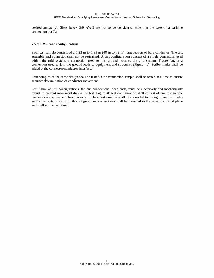
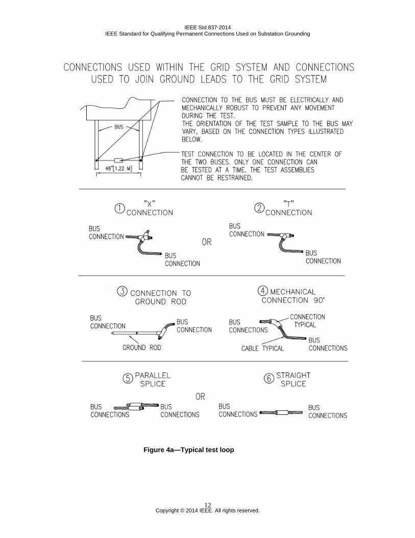
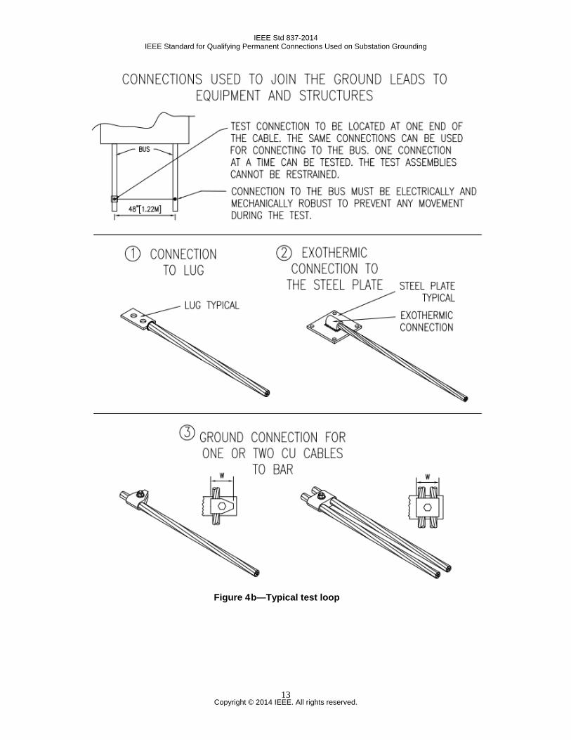
Each test sample consists of a 1.22 m to 1.83 m (48 in to 72 in) long section of bare conductor. The test assembly and connector shall not be restrained. A test configuration consists of a single connection used within the grid system, a connection used to join ground leads to the grid system (Figure 4a), or a connection used to join the ground leads to equipment and structures (Figure 4b). Scribe marks shall be added at the connector/conductor interface.
Four samples of the same design shall be tested. One connection sample shall be tested at a time to ensure accurate determination of conductor movement.
For Figure 4a test configurations, the bus connections (dead ends) must be electrically and mechanically robust to prevent movement during the test. Figure 4b test configuration shall consist of one test sample connector and a dead end bus connection. These test samples shall be connected to the rigid mounted plates and/or bus extensions. In both configurations, connections shall be mounted in the same horizontal plane and shall not be restrained.
Copyright © 2014 IEEE. All rights reserved.
11
IEEE Std 837-2014 IEEE Standard for Qualifying Permanent Connections Used on Substation Grounding
Figure 4a—Typical test loop
Copyright © 2014 IEEE. All rights reserved.
12
IEEE Std 837-2014 IEEE Standard for Qualifying Permanent Connections Used on Substation Grounding
Figure 4 b—Typical test loop
Copyright © 2014 IEEE. All rights reserved.
13
IEEE Std 837-2014 IEEE Standard for Qualifying Permanent Connections Used on Substation Grounding
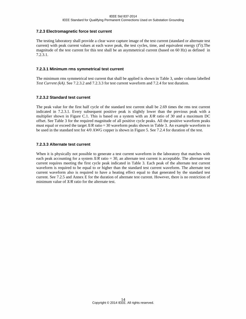
7.2.3 Electromagnetic force test current
The testing laboratory shall provide a clear wave capture image of the test current (standard or alternate test current) with peak current values at each wave peak, the test cycles, time, and equivalent energy (I2t).The magnitude of the test current for this test shall be an asymmetrical current (based on 60 Hz) as defined in 7.2.3.1.
7.2.3.1 Minimum rms symmetrical test current
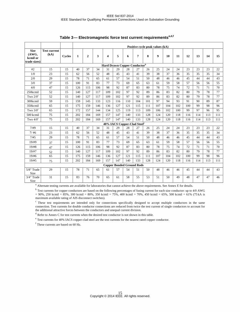
The minimum rms symmetrical test current that shall be applied is shown in Table 3, under column labelled Test Current (kA). See 7.2.3.2 and 7.2.3.3 for test current waveform and 7.2.4 for test duration.
7.2.3.2 Standard test current
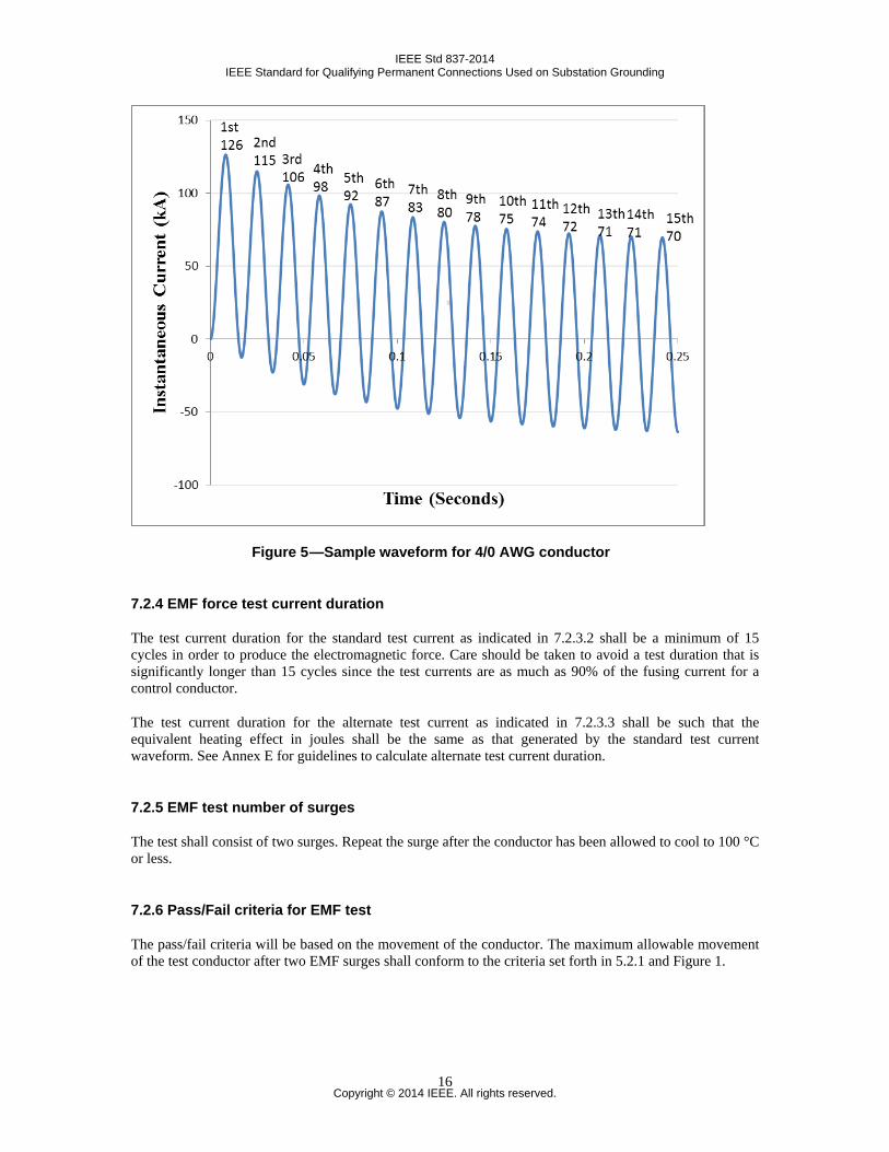
The peak value for the first half cycle of the standard test current shall be 2.69 times the rms test current indicated in 7.2.3.1. Every subsequent positive peak is slightly lower than the previous peak with a multiplier shown in Figure C.1. This is based on a system with an X/R ratio of 30 and a maximum DC offset. See Table 3 for the required magnitude of all positive cycle peaks. All the positive waveform peaks must equal or exceed the target X/R ratio = 30 waveform peaks shown in Table 3. An example waveform to be used in the standard test for 4/0 AWG copper is shown in Figure 5. See 7.2.4 for duration of the test.
7.2.3.3 Alternate test current
When it is physically not possible to generate a test current waveform in the laboratory that matches with each peak accounting for a system X/R ratio = 30, an alternate test current is acceptable. The alternate test current requires meeting the first cycle peak indicated in Table 3. Each peak of the alternate test current waveform is required to be equal to or higher than the standard test current waveform. The alternate test current waveform also is required to have a heating effect equal to that generated by the standard test current. See 7.2.5 and Annex E for the duration of alternate test current. However, there is no restriction of minimum value of X/R ratio for the alternate test.
Copyright © 2014 IEEE. All rights reserved.
14
IEEE Std 837-2014 IEEE Standard for Qualifying Permanent Connections Used on Substation Grounding
Table 3 — Electromagnetic force test current requirementsa,d,f
Positive cycle peak values (kA) Size
(AWG, kcmil or
trade sizes)
Test current (kA) Cycles 1 2 3 4 5 6 7 8 9 10 11 12 13 14 15
Hard Drawn Copper Conductorb #2 15 15 40 37 34 31 29 28 27 26 25 24 24 23 23 23 22 1/0 23 15 62 56 52 48 45 43 41 39 38 37 36 35 35 35 34 2/0 29 15 78 71 65 61 57 54 51 50 48 46 46 45 44 44 43 3/0 37 15 100 91 83 77 73 69 65 63 61 59 58 57 56 56 55 4/0 47 15 126 115 106 98 92 87 83 80 78 75 74 72 71 71 70
250kcmil 52 15 140 127 117 109 102 97 92 89 86 83 82 80 79 78 77 Two 2/0c 52 15 140 127 117 109 102 97 92 89 86 83 82 80 79 78 77 300kcmil 59 15 159 145 133 123 116 110 104 101 97 94 93 91 90 89 87 350kcmil 65 15 175 159 146 136 127 121 115 111 107 104 102 100 99 98 96 Two 3/0c 65 15 172 157 144 134 125 119 113 109 106 102 100 99 97 96 95 500 kcmil 75 15 202 184 169 157 147 140 133 128 124 120 118 116 114 113 111 Two 4/0c 75 15 202 184 169 157 147 140 133 128 124 120 118 116 114 113 111
40% IACS Copper-Clad Steele 7/#9 15 15 40 37 34 31 29 28 27 26 25 24 24 23 23 23 22 7/ #6 23 15 62 56 52 48 45 43 41 39 38 37 36 35 35 35 34 7/#5 29 15 78 71 65 61 57 54 51 50 48 46 46 45 44 44 43
19/#9 37 15 100 91 83 77 73 69 65 63 61 59 58 57 56 56 55 19/#8 47 15 126 115 106 98 92 87 83 80 78 75 74 72 71 71 70 19/#7 52 15 140 127 117 109 102 97 92 89 86 83 82 80 79 78 77 19/#6 65 15 175 159 146 136 127 121 115 111 107 104 102 100 99 98 96 19/#5 75 15 202 184 169 157 147 140 133 128 124 120 118 116 114 113 111
Copper Bonded Ground Rods 5/8" Trade
Size 29 15 78 71 65 61 57 54 51 50 48 46 46 45 44 44 43
3/4" Trade Size
31 15 83 76 70 65 61 58 55 53 51 50 49 48 47 47 46
a Alternate testing currents are available for laboratories that cannot achieve the above requirements. See Annex E for details. b Test currents for copper conductors are based on the following percentages of fusing current for each size conductor: up to 4/0 AWG = 90%, 250 kcmil = 85%, 300 kcmil = 80%, 350 kcmil = 75%, 400 kcmil = 70%, 450 kcmil = 65%, 500 kcmil = 61% (75 kA is maximum available rating of AIS disconnect switches). c These test requirements are intended only for connections specifically designed to accept multiple conductors in the same connection. Test currents for double conductor connections are reduced from twice the test current of single conductors to account for the additional attractive forces between the conductors and unequal current division. d Refer to Annex C for test currents when the desired test conductor is not shown in this table. e Test currents for 40% IACS copper-clad steel are the test currents for the nearest rated copper conductor. f These currents are based on 60 Hz.
Copyright © 2014 IEEE. All rights reserved.
15
IEEE Std 837-2014 IEEE Standard for Qualifying Permanent Connections Used on Substation Grounding
Figure 5 —Sample waveform for 4/0 AWG conductor
7.2.4 EMF force test current duration
The test current duration for the standard test current as indicated in 7.2.3.2 shall be a minimum of 15 cycles in order to produce the electromagnetic force. Care should be taken to avoid a test duration that is significantly longer than 15 cycles since the test currents are as much as 90% of the fusing current for a control conductor.
The test current duration for the alternate test current as indicated in 7.2.3.3 shall be such that the equivalent heating effect in joules shall be the same as that generated by the standard test current waveform. See Annex E for guidelines to calculate alternate test current duration.
7.2.5 EMF test number of surges
The test shall consist of two surges. Repeat the surge after the conductor has been allowed to cool to 100 °C or less.
7.2.6 Pass/Fail criteria for EMF test
The pass/fail criteria will be based on the movement of the conductor. The maximum allowable movement of the test conductor after two EMF surges shall conform to the criteria set forth in 5.2.1 and Figure 1.
Copyright © 2014 IEEE. All rights reserved.
16
IEEE Std 837-2014 IEEE Standard for Qualifying Permanent Connections Used on Substation Grounding
8. Current-temperature cycling test
8.1 General
This test is intended to ensure the conformance to resistance criteria of connections subjected to temperature changes caused by fluctuating currents.
8.2 Current-temperature cycling test
This test shall be the first test conducted in a series of sequential tests, as listed in Table 1 (see Clause 4).
8.2.1 Conductor combinations
When joining different types or sizes of conductors, the selection of the conductor combinations and test current shall be that which results in the highest connection temperature while producing the conductor temperatures specified in Table 6. The following examples are provided to give some direction in maximizing the temperature of the entire test loop, while minimizing the thermal heat-sink properties of the loop components. Example 1: Connection for 19.1–25.4 mm copper-bonded steel rod to 6-2 AWG copper wire. From Table 5, test currents are 19.1 mm rod—570A, 25.4 mm rod—850 A, 6 AWG wire—230 A, 4 AWG wire—320 A, and 2 AWG wire—440 A. Select a 19.1 mm copper-bonded steel rod and 2 AWG copper wire and use an initial test current of 440 A, which should achieve a 350 °C temperature on the 2 AWG wire. Example 2: Connection for 12.7–15.9 mm stainless steel rod to 350–500 kcmil copper wire. From Table 5, test currents are 12.7 mm rod—174 A, 15.9 mm rod—210 A, 350 kcmil wire, 1441 A, and 500 kcmil wire—1860 A. Select a 15.9 mm stainless steel rod and 350 kcmil copper wire and use an initial test current of 210 A, which should achieve a 350 °C temperature on the stainless steel rod. Example 3: Connection for 1/0–2/0 AWG copper wire to 4/0 AWG—250 kcmil copper wire. From Table 5, test currents are 1/0 AWG wire—620 A, 2/0 AWG wire—725 A, 4/0 AWG wire—1010 A, and 250 kcmil wire—1140 A. Select a 2/0 AWG and 4/0 AWG copper wire and use an initial test current of 725 A, which should achieve a 350 °C temperature on the 2/0 AWG copper wire.
8.2.2 Test samples
Four connections shall be required for each series of sequential tests.
8.2.3 Equalizer
Equalizers shall be installed on the stranded conductor on each side of each connection. The equalizer pro-vides an equipotential plane for resistance measurements and prevents the influence of one connection on the other. For equalizer locations refer to Figure 2, Figure 3, and Figure 6. Equalizers are not required on solid conductors.
Any form of equalizer that ensures contact of all strands of a conductor for the duration of the test may be used. The equalizer used on control conductors shall be the same as those used in the test samples.
Copyright © 2014 IEEE. All rights reserved.
17
IEEE Std 837-2014 IEEE Standard for Qualifying Permanent Connections Used on Substation Grounding
When the cables to be joined in a loop are identical, a continuous piece of cable may be used between the connections. A short compression sleeve centered between the connections may then act as the equalizer.
NOTE—Resistance measurement points on solid conductors shall be the same as those used for conductors requiring equalizers.5
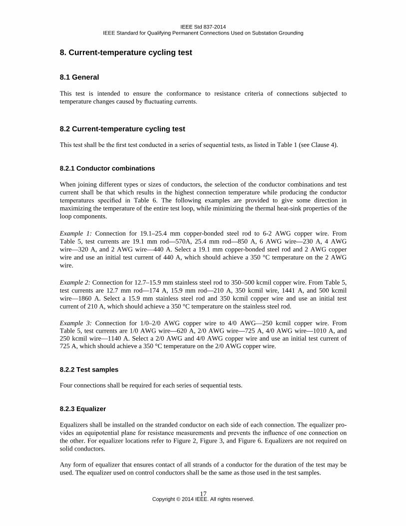
8.2.4 Conductor length
The exposed length of the conductor in the current cycle loop between the connection and the equalizers shall be as given in Table 4.
Table 4 —Conductor length from connection to equalizer
8.3 Ambient conditions
The current-temperature cycling tests shall be conducted in a space free of drafts at an ambient temperature of 10 °C to 40 °C.
8.4 Control conductor
A control conductor, used for the purpose of obtaining conductor temperature, shall be installed in the cur-rent cycle loop between two equalizers. It shall be of the same type and size as the conductor of those joined by the connection under test that established the highest temperature. Its length shall be the same as the total of one test sample between equalizers as shown in Figure 2.
8.5 Current cycling
8.5.1 Current cycling period
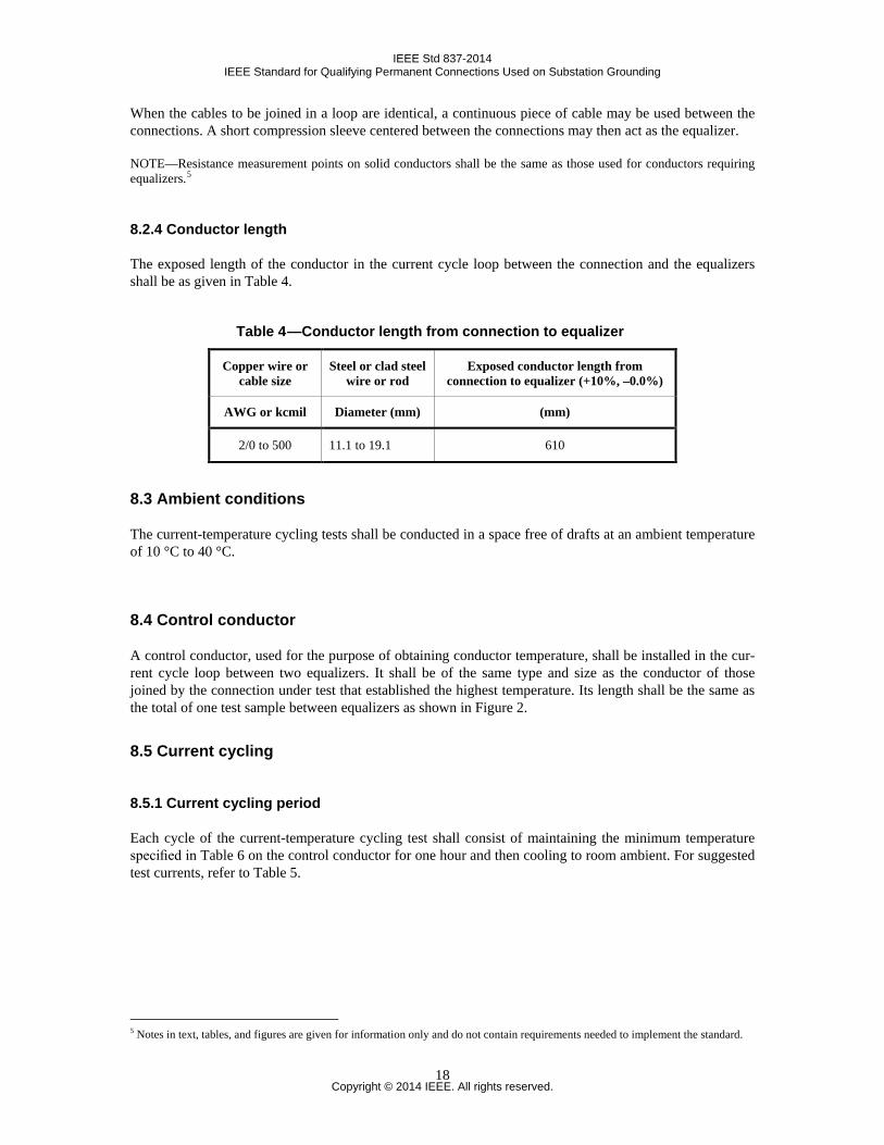
Each cycle of the current-temperature cycling test shall consist of maintaining the minimum temperature specified in Table 6 on the control conductor for one hour and then cooling to room ambient. For suggested test currents, refer to Table 5.
5 Notes in text, tables, and figures are given for information only and do not contain requirements needed to implement the standard.
Copper wire or cable size
Steel or clad steel wire or rod
Exposed conductor length from connection to equalizer (+10%, –0.0%)
AWG or kcmil Diameter (mm) (mm)
2/0 to 500 11.1 to 19.1 610
Copyright © 2014 IEEE. All rights reserved.
18
IEEE Std 837-2014 IEEE Standard for Qualifying Permanent Connections Used on Substation Grounding
Table 5 —Applied current levels
Current cycling suggested test currents for conductor temperatures specified in Table 6
Copper wire size in AWG or kcmil Copper wire sized in mm2 Copper wire amperes
2 34 440
1/0 53 620
2/0 67 725
3/0 85 855
4/0 107 1010
250 127 1140
300 152 1295
350 177 1441
500 253 1860
40% conductivity copper-clad steel conductor size in AWG
40% conductivity copper-clad steel conductor sized in mm2
40% conductivity copper-clad steel amperes
7/#9 46 315
7/#7 74 375
7/#6 93 440
7/#5 117 515
19/#9 126 520
19/#8 159 610
19/#7 200 700
19/#6 247 815
19/#5 319 940 Copper-bonded ground rod
nominal diametera Copper-bonded ground rod
nominal cross sectionb in mm2 Copper-bonded ground rod
amperesc
5/8” Trade Size 162 425
3/4” Trade Size 236 570 a Actual rod diameter may vary from the nominal diameter (see NEMA GR 1) and could require minor current adjustment during testing. b Based on maximum finished diameter from Table 2-1 in NEMA GR 1 (2007). c Copper bonded steel rod based on 0.254 mm copper thickness. d Parameters are computed from AWG, kcmil and trade sizes.
8.5.2 Current cycling number of cycles
The connections shall be subjected to a minimum of 25 current cycles.
8.5.3 Current cycling test temperature
The current shall be adjusted over the first five cycles to result in a steady-state temperature on the control conductor specified in Table 6, and adjusted every five cycles thereafter as required to attain the specified steady-state temperature for a total of 25 cycles.
Copyright © 2014 IEEE. All rights reserved.
19
IEEE Std 837-2014 IEEE Standard for Qualifying Permanent Connections Used on Substation Grounding
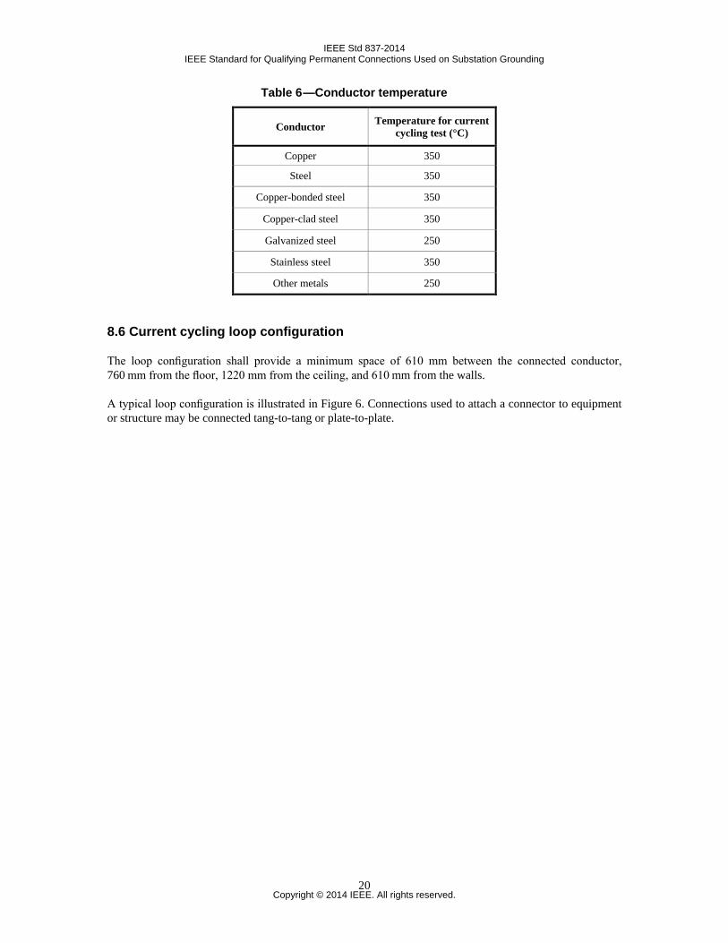
Table 6 —Conductor temperature
8.6 Current cycling loop configuration
The loop configuration shall provide a minimum space of 610 mm between the connected conductor, 760 mm from the floor, 1220 mm from the ceiling, and 610 mm from the walls.
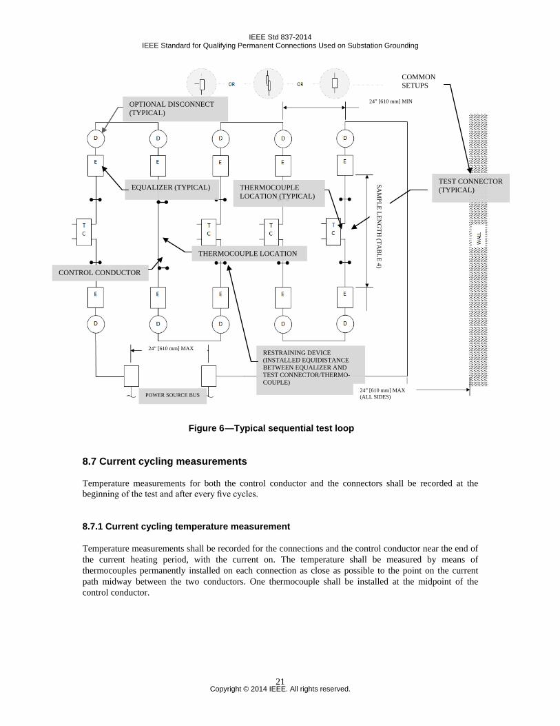
A typical loop configuration is illustrated in Figure 6. Connections used to attach a connector to equipment or structure may be connected tang-to-tang or plate-to-plate.
Conductor Temperature for current cycling test (°C)
Copper 350
Steel 350
Copper-bonded steel 350
Copper-clad steel 350
Galvanized steel 250
Stainless steel 350
Other metals 250
Copyright © 2014 IEEE. All rights reserved.
20
IEEE Std 837-2014 IEEE Standard for Qualifying Permanent Connections Used on Substation Grounding
Figure 6 —Typical sequential test loop
8.7 Current cycling measurements
Temperature measurements for both the control conductor and the connectors shall be recorded at the beginning of the test and after every five cycles.
8.7.1 Current cycling temperature measurement
Temperature measurements shall be recorded for the connections and the control conductor near the end of the current heating period, with the current on. The temperature shall be measured by means of thermocouples permanently installed on each connection as close as possible to the point on the current path midway between the two conductors. One thermocouple shall be installed at the midpoint of the control conductor.
COMMON SETUPS
TEST CONNECTOR (TYPICAL) THERMOCOUPLE
LOCATION (TYPICAL)
24” [610 mm] MIN OPTIONAL DISCONNECT (TYPICAL)
EQUALIZER (TYPICAL)
THERMOCOUPLE LOCATION
RESTRAINING DEVICE (INSTALLED EQUIDISTANCE BETWEEN EQUALIZER AND TEST CONNECTOR/THERMO-COUPLE)
CONTROL CONDUCTOR
24” [610 mm] MAX
24” [610 mm] MAX (ALL SIDES)
SAM
PLE LENG
TH (TA
BLE 4)
POWER SOURCE BUS
Copyright © 2014 IEEE. All rights reserved.
21
IEEE Std 837-2014 IEEE Standard for Qualifying Permanent Connections Used on Substation Grounding
8.7.2 Pass/Fail for current temperature cycling evaluation
The resistance measurements shall meet the requirements of 5.3.2.2.
9. Freeze-thaw test
9.1 General
This test is intended to ensure the conformance to resistance criteria of the connections subjected to repeated cycles of freezing and thawing in water.
9.2 Freeze-thaw test
This test shall be the second test in a series of sequential tests as listed in Table 1.
9.3 Freeze-thaw test samples and their configuration
Test connections are the same test samples subjected to the current-temperature cycling test in accordance with Clause 8.
The samples can be tested in a series loop or as individual test samples.
9.4 Freeze-thaw test equipment
Containers resistant to freezing and heating temperatures and suitable for holding samples in a series loop configuration or as individual samples shall contain enough water to submerge and cover the connection by a minimum of 25.4 mm of water.
9.5 Freeze-thaw test cycle
9.5.1 Freeze-thaw test temperature
The freezing and thawing cycle shall consist of lowering the temperature of the test connection samples to –10 °C or lower, and raising the temperature to at least 20 °C. The test samples shall remain at both the low and high temperature for at least two hours during each cycle.
9.5.2 Freeze-thaw number of cycles
The connection shall be subjected to a minimum of 10 freeze-thaw cycles.
Copyright © 2014 IEEE. All rights reserved.
22

IEEE Std 837-2014 IEEE Standard for Qualifying Permanent Connections Used on Substation Grounding
9.5.3 Pass/Fail for freeze-thaw test evaluation
The resistance measurements shall meet the requirements of 5.3.2.2.
10. Corrosion tests
10.1 General
The corrosion tests are designed to evaluate the corrosion resistance of connections. The acid and salt spray test sequences are independent of each other. Both sequential tests shall be performed for connection qualification to this standard. Plates required for cable-to-rigid connections (exothermic connections and lugs) may be constructed from a corrosion-resistant material. A material, such as 316 stainless steel, may be used to avoid excessive corrosion of the plate.
10.2 Corrosion test-salt spray
10.2.1 General
This test method covers the procedure for determining the corrosive effects of salt spray (sodium chloride) on connections.
10.2.2 Salt spray corrosion test
This test shall be the third test in a series of sequential tests, as shown in Table 1.
10.2.3 Salt spray test samples
The test connection samples shall be the same connections tested in accordance with Clause 8 and Clause 9. A total of four samples are tested.
10.2.4 Salt spray test applicable standard
The test shall be performed according to ASTM B117-11.
10.2.5 Salt spray test duration
The test shall be conducted for a minimum of 500 hours.
10.2.6 Salt spray test post-corrosion conditioning
After completion of the salt spray test, the test samples shall be rinsed in fresh water. Prior to taking resis-tance measurements, samples shall be heated for 1 hour at 100 °C to ensure dryness and then be returned to ambient temperature.
Copyright © 2014 IEEE. All rights reserved.
23
IEEE Std 837-2014 IEEE Standard for Qualifying Permanent Connections Used on Substation Grounding
10.2.7 Salt spray test visual evaluation
Connections and conductors shall be visually inspected for the type of corrosion, if any, and this information shall be recorded in the test data, such as uniform corrosion, pitting, and galvanic action.
10.2.8 Pass/Fail salt spray test evaluation
The resistance measurements shall meet the requirements of 5.3.2.2.
10.3 Corrosion test-acid (HNO3)
10.3.1 General
This test method covers the procedure for determining the corrosive effects of acid attack (nitric acid) on connections.
10.3.2 Acid corrosion test
This test shall be the third test in a series of sequential tests, as shown in Table 1.
10.3.3 Acid test samples
The test connection samples shall be the same connections tested in accordance with Clause 8 and Clause 9.
10.3.4 Acid test submersion and samples
The test samples and conductor up to the equalizers shall be submerged in the acid solution. The equalizers may or may not be included in the submerged section. This setup shall position the connection sample mid-way between exposed loop portions from the acid solution.
The control conductor shall be the same as used in Clause 8 and Clause 9, and the submerged portion shall be equal in length to that of the submerged sample loop section. The beginning resistance of control conductors shall be recorded for reference in accordance with 5.3.2.
A timing control conductor shall be used when using conductor other than copper or copper-clad steel. This timing control conductor will only be subjected to the acid test. It shall include equalizers as in Figure 2 and utilize a copper conductor of the same cross sectional area (within 10% of the cross sectional area) as the sample being tested. This timing control conductor will be used to determine the duration of the acid test.
10.3.5 Acid test solution parameters
The acid solution shall be a 10% by volume concentration of nitric acid HNO3 and distilled water H2O. See Annex B.
Copyright © 2014 IEEE. All rights reserved.
24
IEEE Std 837-2014 IEEE Standard for Qualifying Permanent Connections Used on Substation Grounding
Solution volume shall be such as to provide a minimum ratio of 1 liter of 10% solution to 1.6 × 104 mm2 of submerged test sample surface area. The surface area includes the surface of all strands of the conductor submerged in the solution.
The ambient temperature shall be 20 °C to 35 °C.
10.3.6 Acid test submersion time
Simple conductor loops (i.e., conductors of a single, uniform material such as copper) shall be submerged in the acid solution for a time that will reduce the control conductor to 80% (minimum of 20% reduction) of its original cross-sectional area. The reduction shall be determined by weight reduction per unit length or increase in resistance of the control conductor.
Compound simple conductor loops (i.e., two different single, uniform materials such as a copper conductor joined with a copper-clad steel conductor) shall be submerged in the acid solution for a time that will reduce the faster corroding of the materials to 80% (minimum of 20% reduction) of its original cross-sectional area. The reduction shall be determined by weight reduction per unit length or increase in resistance of the control conductor. When a conductor loop combination includes plated or clad conductors, the minimum submersion time shall be either (1) the same as stated above for simple conductor loops, or (2) the point at which the base material of the plated/clad conductor first becomes exposed anywhere along its length with a minimum continuous area of 10 mm2, whichever event occurs first.
If the conductor loops are stainless steel, the conductors in the sample may not reduce in weight at all. Because of this, in the case that none of the conductors are copper or copper-clad steel, the sample shall be submerged in the acid solution for a time that will reduce the copper control conductor described in 10.3.4 to 80% (minimum of 20% reduction) of its original cross-sectional area. The reduction shall be determined by weight reduction per unit length or increase in resistance of the control conductor.
10.3.7 Acid test post-corrosion conditioning
After completion of the acid test, the test samples shall be rinsed in fresh water and heated for 1 hour at 100 °C to ensure dryness, and then be returned to ambient temperature.
10.3.8 Acid test evaluation
Connections and conductors shall be visually inspected for the type of corrosion, if any, and this information shall be recorded in the test data, such as uniform corrosion, pitting, and galvanic action. The final resistance of plated/clad control conductors shall be recorded per 5.3.2.2.
10.3.9 Pass/Fail acid test evaluation
The resistance measurements shall meet the requirements of 5.3.2.2.
Copyright © 2014 IEEE. All rights reserved.
25
IEEE Std 837-2014 IEEE Standard for Qualifying Permanent Connections Used on Substation Grounding
11. Fault-current test
11.1 General
The purpose of this test is to determine if connections conditioned in previous tests will withstand fault-current surges.
11.2 Fault-current test
This test shall be the fourth test in a series of sequential tests as shown in Table 1 and Figure D.2.
11.3 Fault-current test samples
The test samples shall be the same connection tested in accordance with Clause 8 through Clause 10.
11.4 Fault-current test configuration
The individual test samples shall be mounted in the test loop as shown in Figure 6. The control conductor shall also be tested to 11.2. Use of fastening devices is at the discretion of the tester.
11.5 Fault-current test duration
The fault duration shall be a minimum of 10 seconds.
11.6 Fault-current test current
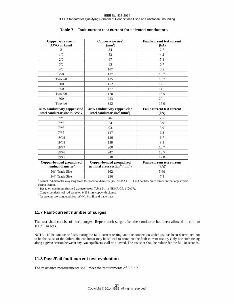
The symmetrical rms fault current shall be 90% of the fusing current for the remaining cross-sectional area of the control conductor calculated for a time of 10 second duration. Test currents for common conductor sizes are listed in Table 7; for all other conductor sizes, see Annex C. Note that Table 7 test currents reflect 90% of the test current of a new conductor and does not apply to the acid sequence conductor. For acid sequence, see Annex C to calculate these values.
NOTE—Ninety percent of the fusing current is established to prevent loss of the conductor and provide a method of measuring resistance readings after three repeated fault surges.
Copyright © 2014 IEEE. All rights reserved.
26
IEEE Std 837-2014 IEEE Standard for Qualifying Permanent Connections Used on Substation Grounding
Table 7 —Fault-current test current for selected conductors
Copper wire size in AWG or kcmil
Copper wire sized
(mm2) Fault-current test current
(kA) 2 34 2.7
1/0 53 4.2 2/0 67 5.4 3/0 85 6.7 4/0 107 8.5 250 127 10.7
Two 2/0 135 10.7 300 152 12.1 350 177 14.1
Two 3/0 170 13.5 500 253 20.1
Two 4/0 322 17.0 40% conductivity copper-clad steel conductor size in AWG
40% conductivity copper-clad steel conductor sized (mm2)
Fault-current test current (kA)
7/#9 46 2.5 7/#7 74 3.9 7/#6 93 5.0 7/#5 117 6.3 19/#9 126 6.7 19/#8 159 8.5 19/#7 200 10.7 19/#6 247 13.5 19/#5 318 17.0
Copper-bonded ground rod nominal diametera
Copper-bonded ground rod nominal cross sectionb (mm2)
Fault-current test current (kA)c
5/8" Trade Size 162 5.60 3/4" Trade Size 236 7.8
a Actual rod diameter may vary from the nominal diameter (see NEMA GR 1) and could require minor current adjustment during testing. b Based on maximum finished diameter from Table 2-1 in NEMA GR 1 (2007). c Copper bonded steel rod based on 0.254 mm copper thickness. d Parameters are computed from AWG, kcmil, and trade sizes.
11.7 Fault-current number of surges
The test shall consist of three surges. Repeat each surge after the conductor has been allowed to cool to 100 °C or less.
NOTE—If the conductor fuses during the fault-current testing, and the connection under test has been determined not to be the cause of the failure, the conductor may be spliced to complete the fault-current testing. Only one such fusing along a given section between any two equalizers shall be allowed. The test shot shall be redone for the full 10 seconds.
11.8 Pass/Fail fault-current test evaluation
The resistance measurements shall meet the requirements of 5.3.2.2.
Copyright © 2014 IEEE. All rights reserved.
27
IEEE Std 837-2014 IEEE Standard for Qualifying Permanent Connections Used on Substation Grounding
Annex A
(informative)
Bibliography
Bibliographical references are resources that provide additional or helpful material but do not need to be understood or used to implement this standard. Reference to these resources is made for informational use only.
[B1] ANSI/UL 467-1984, Safety Standard for Grounding and Bonding Equipment.
[B2] ANSI/UL 486A-1982, Safety Standard for Wire Connectors and Soldering Lugs for Use with Copper Conductors.
[B3] IEEE Std 80™, IEEE Guide for Safety in AC Substation Grounding.
[B4] Mixon, J., Corrosion Resistance Test for Copper and Copper Alloy Connector Products Used on Grounding Grid Conductors and Electrodes. Harrisburg, PA: AMP, Inc., June 27, 1979.
[B5] Mixon, J., Exploratory Acid Corrosion Tests. Harrisburg, PA: AMP, Inc., Oct. 5, 1978.
[B6] NACE TM0169-95, Laboratory Corrosion Testing of Metals for the Process Industries.
[B7] NEMA CC1-1993, Electrical Power Connectors for Substations.
[B8] NEMA CC3-1973 (R 1983), Connectors for Use Between Aluminum or Aluminum/Copper Overhead vol. PAS-101, pp. 4006–4023, Oct. 1982 (IEEE Paper 82 WM 180-8).
[B9] Sverak, J. G., “Safe substation grounding, Part II,” IEEE Transactions on Power Apparatus and Systems.
[B10] Sverak, J. G., “Sizing of ground conductors against fusing,” IEEE Transactions on Power Apparatus and Systems, vol. PAS-100, pp. 51–59, Jan. 1981 (IEEE Paper F80 256-8).
[B11] VDE Standard 0142.64, Regulation for Earthings in AC Installation with Rated Voltages Above 1 kV (Germany).
Copyright © 2014 IEEE. All rights reserved.
28
IEEE Std 837-2014 IEEE Standard for Qualifying Permanent Connections Used on Substation Grounding
Annex B
(informative)
Nitric-acid dilution
NOTE—Nitric acid, HNO3, is usually purchased as 70% concentrate and is adjusted to the percentage requirement for
the user by the following calculation per liter of solution.
%70%10mL1000)mL(3
×=⋅⋅ HNOofVolume per liter
Volume of HNO3 (mL) = 143 mL of HNO3 per liter
143 mL of 70% nitric acid concentrate + 857 mL of water = 1 liter of 10% acid test solution.
Copyright © 2014 IEEE. All rights reserved.
29
IEEE Std 837-2014 IEEE Standard for Qualifying Permanent Connections Used on Substation Grounding
Annex C
(normative)
Conductive ampacity calculation
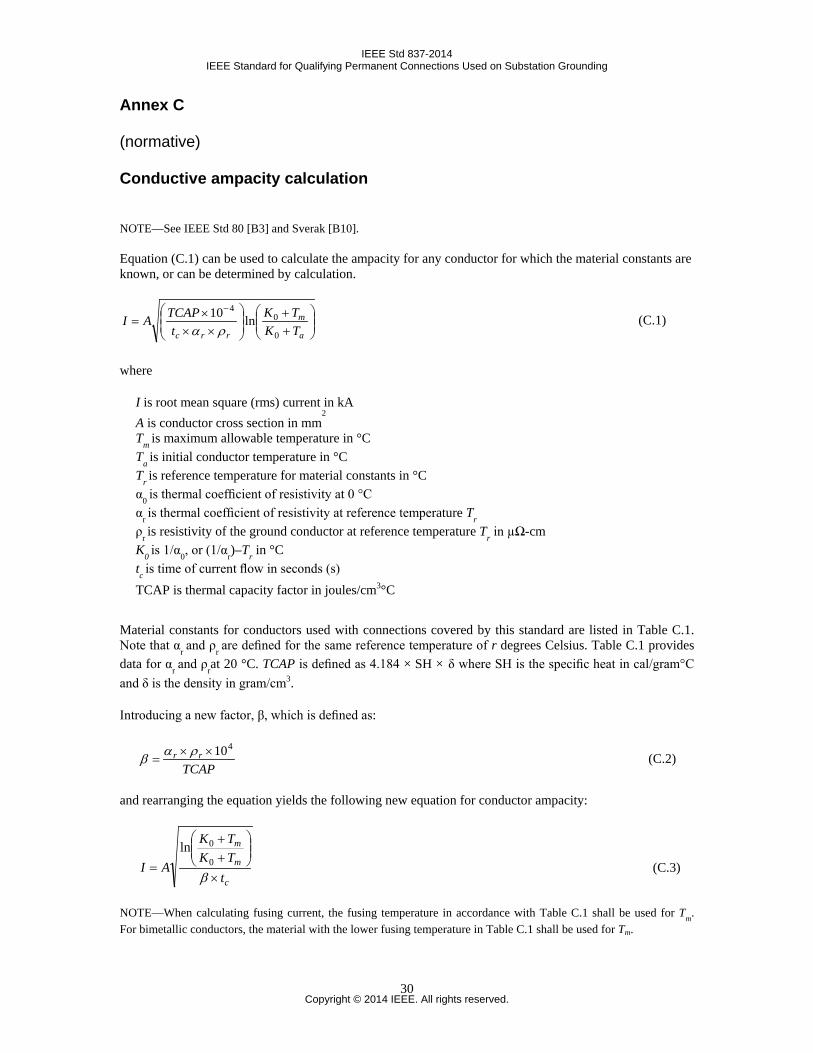
NOTE—See IEEE Std 80 [B3] and Sverak [B10]. Equation (C.1) can be used to calculate the ampacity for any conductor for which the material constants are known, or can be determined by calculation.
++
×××
=−
a
m
rrc TKTK
tTCAPAI
0
04
ln10ρα
(C.1)
where
I is root mean square (rms) current in kA A is conductor cross section in mm
2
Tm is maximum allowable temperature in °C Ta is initial conductor temperature in °C Tr is reference temperature for material constants in °C α0 is thermal coefficient of resistivity at 0 °C αr is thermal coefficient of resistivity at reference temperature Tr ρr is resistivity of the ground conductor at reference temperature Tr in µΩ-cm K0 is 1/α0, or (1/αr)–Tr in °C tc is time of current flow in seconds (s) TCAP is thermal capacity factor in joules/cm3°C
Material constants for conductors used with connections covered by this standard are listed in Table C.1. Note that αr and ρr are defined for the same reference temperature of r degrees Celsius. Table C.1 provides data for αr and ρrat 20 °C. TCAP is defined as 4.184 × SH × δ where SH is the specific heat in cal/gram°C and δ is the density in gram/cm3.
Introducing a new factor, β, which is defined as:
TCAPrr
410××=
ραβ (C.2)
and rearranging the equation yields the following new equation for conductor ampacity:
c
m
m
tTKTK
AI×
++
=β
0
0ln (C.3)
NOTE—When calculating fusing current, the fusing temperature in accordance with Table C.1 shall be used for Tm. For bimetallic conductors, the material with the lower fusing temperature in Table C.1 shall be used for Tm.
Copyright © 2014 IEEE. All rights reserved.
30
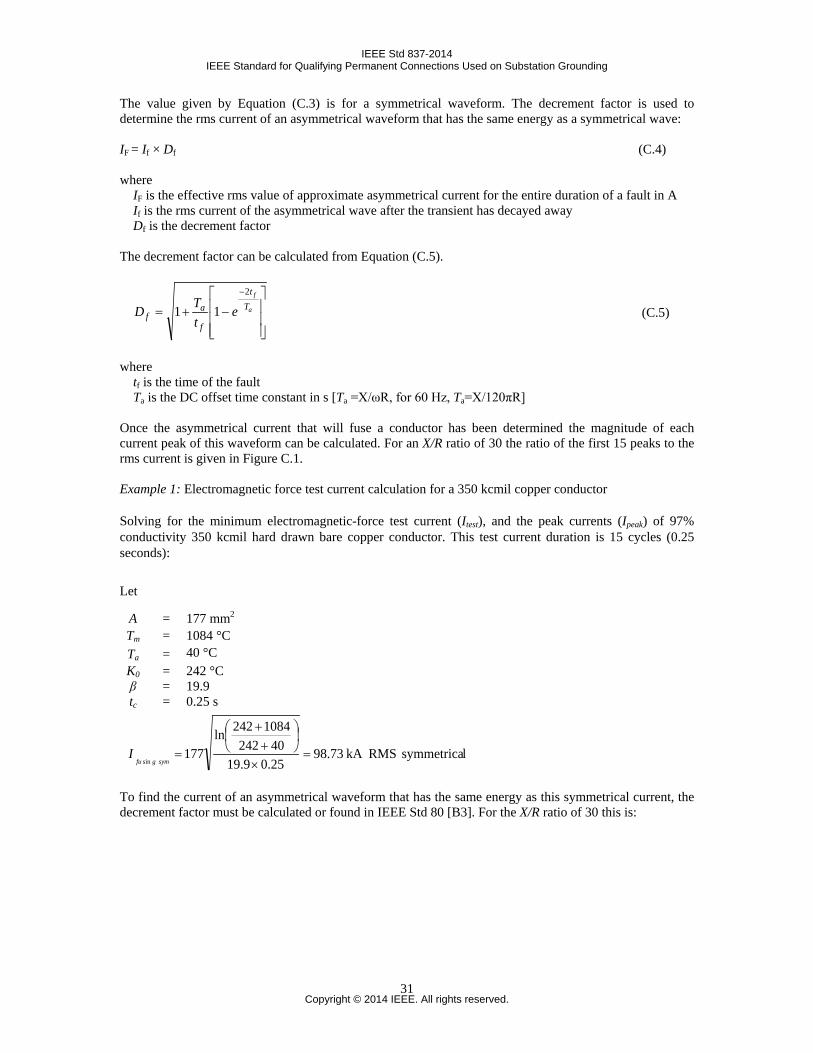
IEEE Std 837-2014 IEEE Standard for Qualifying Permanent Connections Used on Substation Grounding
The value given by Equation (C.3) is for a symmetrical waveform. The decrement factor is used to determine the rms current of an asymmetrical waveform that has the same energy as a symmetrical wave: IF = If × Df (C.4) where
IF is the effective rms value of approximate asymmetrical current for the entire duration of a fault in A If is the rms current of the asymmetrical wave after the transient has decayed away Df is the decrement factor
The decrement factor can be calculated from Equation (C.5).
−+=
−
a
f
Tt
f
af e
tTD
2
11 (C.5)
where
tf is the time of the fault Ta is the DC offset time constant in s [Ta =X/ωR, for 60 Hz, Ta=X/120πR]
Once the asymmetrical current that will fuse a conductor has been determined the magnitude of each current peak of this waveform can be calculated. For an X/R ratio of 30 the ratio of the first 15 peaks to the rms current is given in Figure C.1. Example 1: Electromagnetic force test current calculation for a 350 kcmil copper conductor
Solving for the minimum electromagnetic-force test current (Itest), and the peak currents (Ipeak) of 97% conductivity 350 kcmil hard drawn bare copper conductor. This test current duration is 15 cycles (0.25 seconds):
lsymmetrica RMSkA 73.9825.09.1940242
1084242ln177
sin=
×
++
=symgfu
I
To find the current of an asymmetrical waveform that has the same energy as this symmetrical current, the decrement factor must be calculated or found in IEEE Std 80 [B3]. For the X/R ratio of 30 this is:
Let
A = 177 mm2 Tm = 1084 °C Ta = 40 °C K0 = 242 °C β = 19.9 tc = 0.25 s
Copyright © 2014 IEEE. All rights reserved.
31
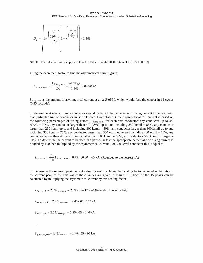
IEEE Std 837-2014 IEEE Standard for Qualifying Permanent Connections Used on Substation Grounding
148.1125.0
12030
1 12030
25.02
=
−
+=
×−
ππ eD f
NOTE—The value for this example was found in Table 10 of the 2000 edition of IEEE Std 80 [B3].
Using the decrement factor to find the asymmetrical current gives:
kA00.86148.1
kA73.98sinsin ===
f
symgfuasymgfu D
II
Ifusing asym is the amount of asymmetrical current at an X/R of 30, which would fuse the copper in 15 cycles (0.25 seconds).
To determine at what current a connector should be tested, the percentage of fusing current to be used with that particular size of conductor must be known. From Table 3, the asymmetrical test current is based on the following percentages of fusing current, Ifusing asym, for each size conductor: any conductor up to 4/0 AWG = 90%, any conductor larger than 4/0 AWG up to and including 250 kcmil = 85%, any conductor larger than 250 kcmil up to and including 300 kcmil = 80%, any conductor larger than 300 kcmil up to and including 350 kcmil = 75%, any conductor larger than 350 kcmil up to and including 400 kcmil = 70%, any conductor larger than 400 kcmil and smaller than 500 kcmil = 65%, all conductors 500 kcmil or larger = 61%. To determine the current to be used in a particular test the appropriate percentage of fusing current is divided by 100 then multiplied by the asymmetrical current. For 350 kcmil conductor this is equal to:
kA6500.8675.010075
sin =×== asymgfuasymtest II (Rounded to the nearest kA)
To determine the required peak current value for each cycle another scaling factor required is the ratio of the current peak to the rms value; these values are given in Figure C.1. Each of the 15 peaks can be calculated by multiplying the asymmetrical current by this scaling factor.
kA)nearest to(RoundedkA 1756569.269.2 =×== asymtestpeakfirst II
kA1596545.245.2sec =×== asymtestpeakond II
kA 1466525.225.2 =×== asymtestpeakthird II
…
kA 966548.148.1 =×== asymtestpeakfifteenth II
Copyright © 2014 IEEE. All rights reserved.
32
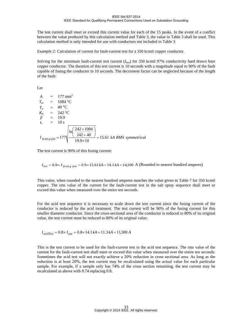
IEEE Std 837-2014 IEEE Standard for Qualifying Permanent Connections Used on Substation Grounding
The test current shall meet or exceed this current value for each of the 15 peaks. In the event of a conflict between the value produced by this calculation method and Table 3, the value in Table 3 shall be used. This calculation method is only intended for use with conductors not included in Table 3.
Example 2: Calculation of current for fault-current test for a 350 kcmil copper conductor.
Solving for the minimum fault-current test current (Itest) for 350 kcmil 97% conductivity hard drawn bare copper conductor. The duration of this test current is 10 seconds with a magnitude equal to 90% of the fault capable of fusing the conductor in 10 seconds. The decrement factor can be neglected because of the length of the fault:
lsymmetricaRMSkAI symgfu 61.15109.1940242
1084242ln177sin =
×
++
=
The test current is 90% of this fusing current:
100,14 1.14 61.159.09.0 sin ==×=×= kAkAII symgfutest A (Rounded to nearest hundred amperes)
This value, when rounded to the nearest hundred amperes matches the value given in Table 7 for 350 kcmil copper. The rms value of the current for the fault-current test in the salt spray sequence shall meet or exceed this value when measured over the entire ten seconds.
For the acid test sequence it is necessary to scale down the test current since the fusing current of the conductor is reduced by the acid treatment. The test current will be 90% of the fusing current for this smaller diameter conductor. Since the cross-sectional area of the conductor is reduced to 80% of its original value, the test current must be reduced to 80% of its original value.
AkAkAII testacidTest 300,11 3.11 1.148.08.0 ==×=×=
This is the test current to be used for the fault-current test in the acid test sequence. The rms value of the current for the fault-current test shall meet or exceed this value when measured over the entire ten seconds. Sometimes the acid test will not exactly achieve a 20% reduction in cross sectional area. As long as the reduction is at least 20%, the test current may be recalculated using the actual value for each particular sample. For example, if a sample only has 74% of the cross section remaining, the test current may be recalculated as above with 0.74 replacing 0.8.
Let
A = 177 mm2 Tm = 1084 °C Ta = 40 °C K0 = 242 °C β = 19.9 tc = 10 s
Copyright © 2014 IEEE. All rights reserved.
33

IEEE Std 837-2014 IEEE Standard for Qualifying Permanent Connections Used on Substation Grounding
Example 3: The following shows an example EMF test current calculation for a ¾” copper bonded ground rod:
Since this material does not match any of those given in Table C.1 it is necessary to calculate the thermal capacity and average resistivity before calculating the fusing current. The calculation methods applied here are further described in IEEE Std 80 [B3]. Information on ¾” ground rods is included in ANSI/NEMA GR 1. Per that standard a ¾” ground rod has a minimum finished diameter of 1.709 cm (0.673 in) and a minimum copper thickness of 0.025cm (0.01 in).
To calculate the thermal capacity both an average specific heat and an average density for the ground rod are calculated.
( ) 2222 356.04.229294.2709.14
inmmcmATotalArea Clad =====π
( ) 222 335.0162.205.0709.14
incmASteelArea i ==−==π
( ) 2222 0205.0132.0659.1709.14
incmACopperArea o ==−==π
935.0)132.0)(95.8()162.2)(87.7(
)162.2)(87.7(=
+=
+==
ooii
iii ADAD
ADwSteelFractionMass
065.0)132.0)(95.8()162.2)(87.7(
)132.0)(95.8(=
+=
+==
ooii
iio ADAD
ADwCopperFractionMass
CgJcwcwcHeatSpecificAverage poopiipav °
479.0)385.0)(065.0()486.0)(935.0( =+=+==
393.7132.016.2
)132.0)(95.8()162.2)(87.7(cm
gAA
ADADLALA
LADLADVVmmD
oi
ooii
rori
roorii
oi
oiav =
++
=++
=++
=++
=
where
Ai is the area of inner layer, cm2 Ao is the area of outer layer, cm2 Aclad area of a bimetallic rod or wire, cm2
cpi is the specific heat of inner layer, J/(g°C) cpo is the specific heat of outer layer, J/(g°C) cpav is the average specific, J/(g°C) Di is the density of inner layer, g/cm3 Do is the density of outer layer, g/cm3 Dav is the average density, g/cm3 mi is the mass of inner layer, g mo is the mass of outer layer, g Vi is the volume of the inner layer, cm3 Vo is the volume of the inner layer, cm3 wi is the mass fraction of inner layer wo is the mass fraction of outer layer Lr is the length of the ground rod or wire, m
Copyright © 2014 IEEE. All rights reserved.
34
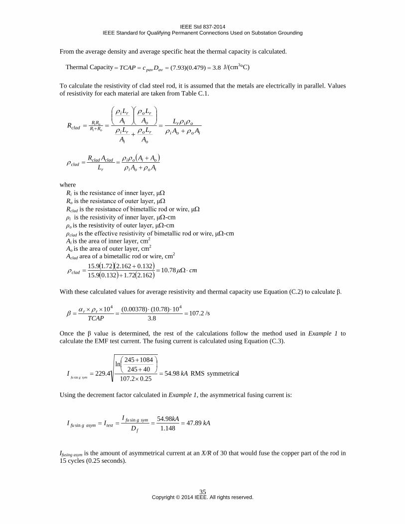
IEEE Std 837-2014 IEEE Standard for Qualifying Permanent Connections Used on Substation Grounding
From the average density and average specific heat the thermal capacity is calculated.
Thermal Capacity 8.3)479.0)(93.7( ==== avpavDcTCAP J/(cm3°C)
To calculate the resistivity of clad steel rod, it is assumed that the metals are electrically in parallel. Values of resistivity for each material are taken from Table C.1.
iooi
oir
o
ro
i
ri
o
ro
i
ri
RRRR
clad AAL
AL
AL
AL
AL
Roi
oi
ρρρρ
ρρ
ρρ
+=
+
== +
( )iooi
oioi
r
cladcladclad AA
AAL
ARρρ
ρρρ
++
==
where Ri is the resistance of inner layer, μΩ Ro is the resistance of outer layer, μΩ Rclad is the resistance of bimetallic rod or wire, μΩ ρi is the resistivity of inner layer, μΩ-cm ρo is the resistivity of outer layer, μΩ-cm ρclad is the effective resistivity of bimetallic rod or wire, μΩ-cm Ai is the area of inner layer, cm2 Ao is the area of outer layer, cm2 Aclad area of a bimetallic rod or wire, cm2
( )( )( ) ( ) cmclad ⋅Ω=
++
= µρ 78.10162.272.1132.09.15132.0162.272.19.15
With these calculated values for average resistivity and thermal capacity use Equation (C.2) to calculate β.
2.1078.3
10)78.10()00378.0(10 44=
⋅⋅=
××=
TCAPrr ραβ /s
Once the β value is determined, the rest of the calculations follow the method used in Example 1 to calculate the EMF test current. The fusing current is calculated using Equation (C.3).
lsymmetrica RMS 98.5425.02.10740245
1084245ln4.229
sinkAI
symgfu=
×
++
=
Using the decrement factor calculated in Example 1, the asymmetrical fusing current is:
kAkAD
III
f
symgfutestasymgfu 89.47
148.198.54sin
sin ====
Ifusing asym is the amount of asymmetrical current at an X/R of 30 that would fuse the copper part of the rod in 15 cycles (0.25 seconds).
Copyright © 2014 IEEE. All rights reserved.
35
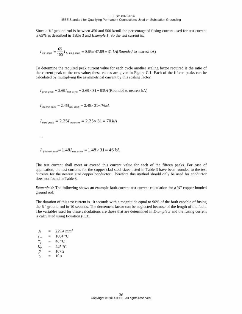
IEEE Std 837-2014 IEEE Standard for Qualifying Permanent Connections Used on Substation Grounding
Since a ¾" ground rod is between 450 and 500 kcmil the percentage of fusing current used for test current is 65% as described in Table 3 and Example 1. So the test current is:
kA)nearest to(3189.4765.010065
sin RoundedkAII asymgfuasymtest =×==
To determine the required peak current value for each cycle another scaling factor required is the ratio of the current peak to the rms value; these values are given in Figure C.1. Each of the fifteen peaks can be calculated by multiplying the asymmetrical current by this scaling factor.
kA)nearest to(Rounded 833169.269.2 kAII asymtestpeakfirst =×==
kAII asymtestpeakond 763145.245.2sec =×==
kAII asymtestpeakthird 703125.225.2 =×==
…
kAII asymtestpeakfifteenth 463148.148.1 =×==
The test current shall meet or exceed this current value for each of the fifteen peaks. For ease of application, the test currents for the copper clad steel sizes listed in Table 3 have been rounded to the test currents for the nearest size copper conductor. Therefore this method should only be used for conductor sizes not found in Table 3. Example 4: The following shows an example fault-current test current calculation for a ¾" copper bonded ground rod:
The duration of this test current is 10 seconds with a magnitude equal to 90% of the fault capable of fusing the ¾" ground rod in 10 seconds. The decrement factor can be neglected because of the length of the fault. The variables used for these calculations are those that are determined in Example 3 and the fusing current is calculated using Equation (C.3).
A = 229.4 mm2 Tm = 1084 °C Ta = 40 °C K0 = 245 °C β = 107.2 tc = 10 s
Copyright © 2014 IEEE. All rights reserved.
36
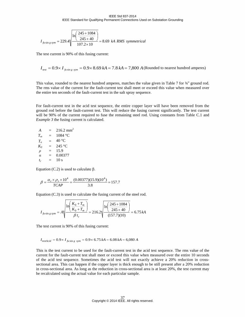
IEEE Std 837-2014 IEEE Standard for Qualifying Permanent Connections Used on Substation Grounding
lsymmetricaRMSkAI symgfu 69.8102.10740245
1084245ln4.229sin =
×
++
=
The test current is 90% of this fusing current:
AkAkAII symgfutest 800,7 8.7 69.89.09.0 sin ==×=×= (Rounded to nearest hundred amperes)
This value, rounded to the nearest hundred amperes, matches the value given in Table 7 for ¾" ground rod. The rms value of the current for the fault-current test shall meet or exceed this value when measured over the entire ten seconds of the fault-current test in the salt spray sequence.
For fault-current test in the acid test sequence, the entire copper layer will have been removed from the ground rod before the fault-current test. This will reduce the fusing current significantly. The test current will be 90% of the current required to fuse the remaining steel rod. Using constants from Table C.1 and Example 3 the fusing current is calculated.
Equation (C.2) is used to calculate β.
7.1578.3
)10)(9.15)(00377.0(10 44==
××=
TCAPrr ραβ
Equation (C.3) is used to calculate the fusing current of the steel rod.
kAt
TKTK
AIc
m
m
symgfu 75.6)10)(7.157(
402451084245ln
2.216ln
0
0
sin =
++
=
++
=β
The test current is 90% of this fusing current:
AkAkAII symgfutestAcid 080,6 08.6 75.69.09.0 sin ==×=×= This is the test current to be used for the fault-current test in the acid test sequence. The rms value of the current for the fault-current test shall meet or exceed this value when measured over the entire 10 seconds of the acid test sequence. Sometimes the acid test will not exactly achieve a 20% reduction in cross-sectional area. This can happen if the copper layer is thick enough to be still present after a 20% reduction in cross-sectional area. As long as the reduction in cross-sectional area is at least 20%, the test current may be recalculated using the actual value for each particular sample.
A = 216.2 mm2 Tm = 1084 °C Ta = 40 °C K0 = 245 °C ρ = 15.9 α = 0.00377 tc = 10 s
Copyright © 2014 IEEE. All rights reserved.
37
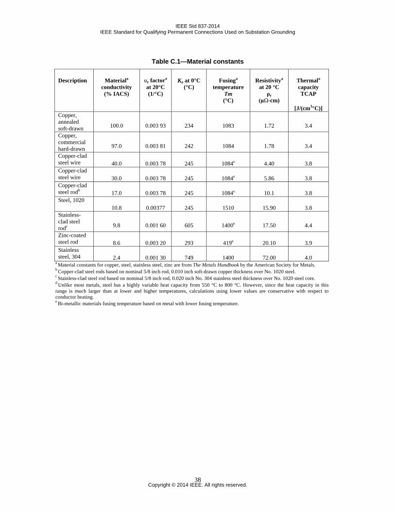
IEEE Std 837-2014 IEEE Standard for Qualifying Permanent Connections Used on Substation Grounding
Table C.1—Material constants
Description Materiala conductivity (% IACS)
αr factora at 20°C (1/°C)
Ko at 0°C (°C)
Fusinga temperature
Tm (°C)
Resistivitya at 20 °C
ρr (μΩ-cm)
Thermala capacity TCAP
[J/(cm3°C)] Copper, annealed soft-drawn 100.0 0.003 93 234 1083 1.72 3.4
Copper, commercial hard-drawn 97.0 0.003 81 242 1084 1.78 3.4
Copper-clad steel wire 40.0 0.003 78 245 1084e 4.40 3.8 Copper-clad steel wire 30.0 0.003 78 245 1084e 5.86 3.8 Copper-clad steel rodb 17.0 0.003 78 245 1084e 10.1 3.8 Steel, 1020
10.8 0.00377 245 1510 15.90 3.8 Stainless-clad steel rodc 9.8 0.001 60 605 1400e 17.50 4.4
Zinc-coated steel rod 8.6 0.003 20 293 419e 20.10 3.9 Stainless steel, 304 2.4 0.001 30 749 1400 72.00 4.0
a Material constants for copper, steel, stainless steel, zinc are from The Metals Handbook by the American Society for Metals. b Copper-clad steel rods based on nominal 5/8 inch rod, 0.010 inch soft-drawn copper thickness over No. 1020 steel. c Stainless-clad steel rod based on nominal 5/8 inch rod, 0.020 inch No. 304 stainless steel thickness over No. 1020 steel core. d Unlike most metals, steel has a highly variable heat capacity from 550 °C to 800 °C. However, since the heat capacity in this range is much larger than at lower and higher temperatures, calculations using lower values are conservative with respect to conductor heating. e Bi-metallic materials fusing temperature based on metal with lower fusing temperature.
Copyright © 2014 IEEE. All rights reserved.
38
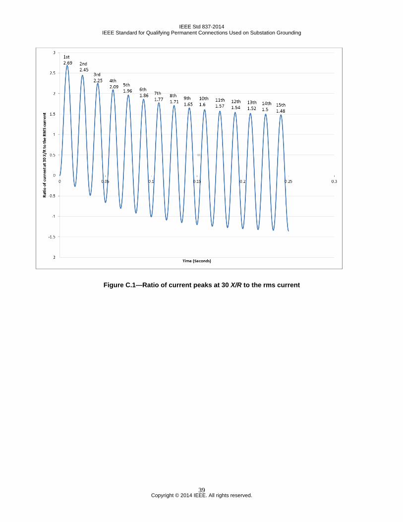
IEEE Std 837-2014 IEEE Standard for Qualifying Permanent Connections Used on Substation Grounding
Figure C.1—Ratio of current peaks at 30 X/R to the rms current
Copyright © 2014 IEEE. All rights reserved.
39
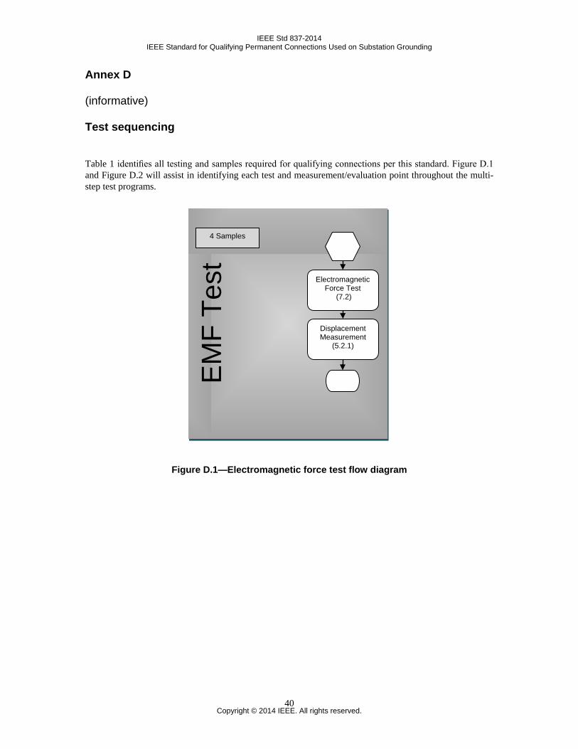
IEEE Std 837-2014 IEEE Standard for Qualifying Permanent Connections Used on Substation Grounding
Annex D
(informative)
Test sequencing
Table 1 identifies all testing and samples required for qualifying connections per this standard. Figure D.1 and Figure D.2 will assist in identifying each test and measurement/evaluation point throughout the multi-step test programs.
Figure D.1—Electromagnetic force test flow diagram
EM
F Te
st
Electromagnetic Force Test
(7.2)
Displacement Measurement
(5.2.1)
4 Samples
Copyright © 2014 IEEE. All rights reserved.
40
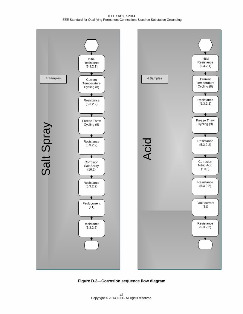
IEEE Std 837-2014 IEEE Standard for Qualifying Permanent Connections Used on Substation Grounding
Figure D.2—Corrosion sequence flow diagram
Aci
d
Sal
t Spr
ay
Initial Resistance
(5.3.2.1)
Current Temperature Cycling (8)
Resistance (5.3.2.2)
Freeze Thaw Cycling (9)
Corrosion Salt Spray
(10.2)
Resistance (5.3.2.2)
Resistance (5.3.2.2)
Fault current (11)
Resistance (5.3.2.2)
Initial Resistance
(5.3.2.1)
Current Temperature Cycling (8)
Resistance (5.3.2.2)
Freeze Thaw Cycling (9)
Corrosion Nitric Acid
(10.3)
Resistance (5.3.2.2)
Resistance (5.3.2.2)
Fault current (11)
Resistance (5.3.2.2)
4 Samples 4 Samples
Copyright © 2014 IEEE. All rights reserved.
41
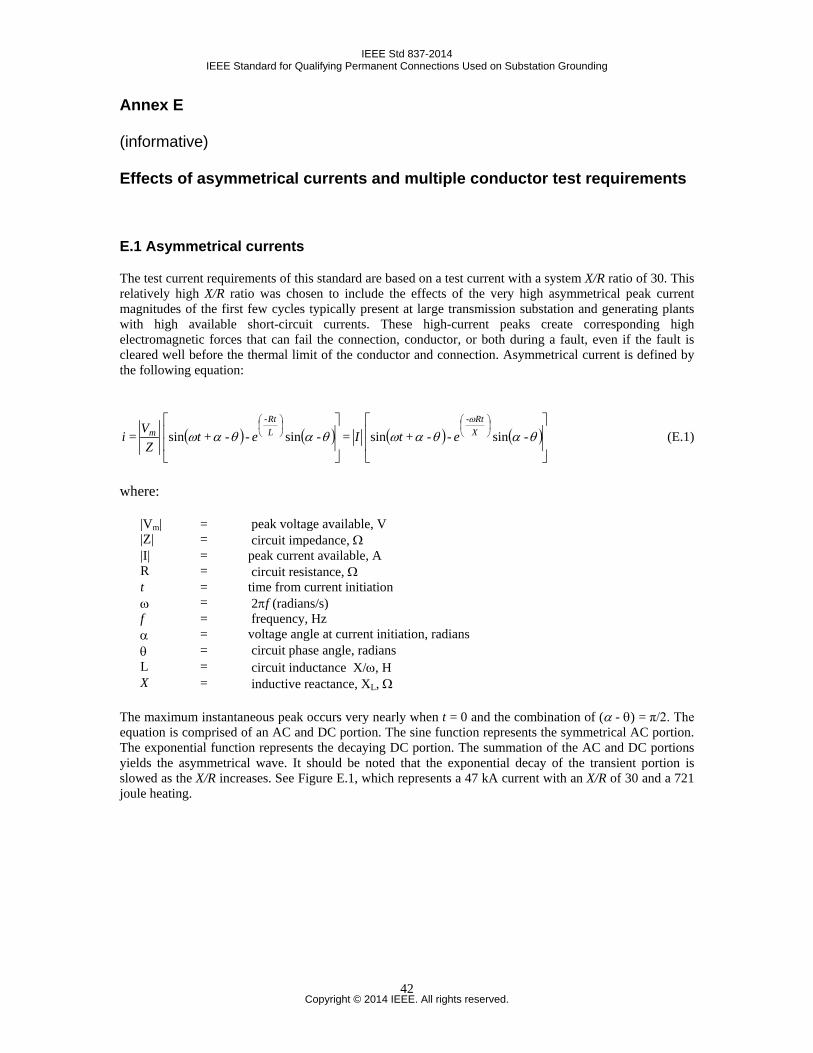
IEEE Std 837-2014 IEEE Standard for Qualifying Permanent Connections Used on Substation Grounding
Annex E
(informative)
Effects of asymmetrical currents and multiple conductor test requirements
E.1 Asymmetrical currents
The test current requirements of this standard are based on a test current with a system X/R ratio of 30. This relatively high X/R ratio was chosen to include the effects of the very high asymmetrical peak current magnitudes of the first few cycles typically present at large transmission substation and generating plants with high available short-circuit currents. These high-current peaks create corresponding high electromagnetic forces that can fail the connection, conductor, or both during a fault, even if the fault is cleared well before the thermal limit of the conductor and connection. Asymmetrical current is defined by the following equation:
i = ( ) ( )
θαθαω -sin - -+sin -LRt
m etZ
V = ( ) ( )
θαθαωω
-sin - -+sin -
XRt
etI (E.1)
where:
|Vm| = peak voltage available, V |Z| = circuit impedance, Ω |I| = peak current available, A R = circuit resistance, Ω t = time from current initiation ω = 2πf (radians/s) f = frequency, Hz α = voltage angle at current initiation, radians θ = circuit phase angle, radians L = circuit inductance X/ω, H X = inductive reactance, XL, Ω
The maximum instantaneous peak occurs very nearly when t = 0 and the combination of (α - θ) = π/2. The equation is comprised of an AC and DC portion. The sine function represents the symmetrical AC portion. The exponential function represents the decaying DC portion. The summation of the AC and DC portions yields the asymmetrical wave. It should be noted that the exponential decay of the transient portion is slowed as the X/R increases. See Figure E.1, which represents a 47 kA current with an X/R of 30 and a 721 joule heating.
Copyright © 2014 IEEE. All rights reserved.
42
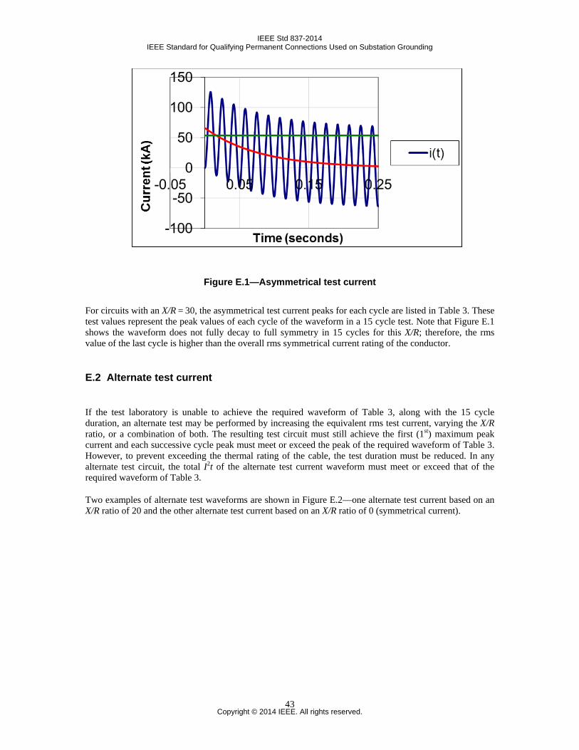
IEEE Std 837-2014 IEEE Standard for Qualifying Permanent Connections Used on Substation Grounding
Figure E.1—Asymmetrical test current
For circuits with an X/R = 30, the asymmetrical test current peaks for each cycle are listed in Table 3. These test values represent the peak values of each cycle of the waveform in a 15 cycle test. Note that Figure E.1 shows the waveform does not fully decay to full symmetry in 15 cycles for this X/R; therefore, the rms value of the last cycle is higher than the overall rms symmetrical current rating of the conductor.
E.2 Alternate test current
If the test laboratory is unable to achieve the required waveform of Table 3, along with the 15 cycle duration, an alternate test may be performed by increasing the equivalent rms test current, varying the X/R ratio, or a combination of both. The resulting test circuit must still achieve the first (1st) maximum peak current and each successive cycle peak must meet or exceed the peak of the required waveform of Table 3. However, to prevent exceeding the thermal rating of the cable, the test duration must be reduced. In any alternate test circuit, the total I2t of the alternate test current waveform must meet or exceed that of the required waveform of Table 3.
Two examples of alternate test waveforms are shown in Figure E.2—one alternate test current based on an X/R ratio of 20 and the other alternate test current based on an X/R ratio of 0 (symmetrical current).
Copyright © 2014 IEEE. All rights reserved.
43
IEEE Std 837-2014 IEEE Standard for Qualifying Permanent Connections Used on Substation Grounding
-150
-100
-50
0
50
100
150
200
0 0.05 0.1 0.15 0.2 0.25Cur
rent
(kA
)
Time (seconds)
i(t) alt 2 x/r20l
i(t) assymtrical
i(t) alt 3 x/r 0
4
Figure E.2—Illustration of two examples of alternate test wave forms
E.3 Testing for multiple cables and individual connections
Clause 7 includes test requirements for single cables in single connections, as well as a limited number of two cables terminated in connections specifically designed for multiple cables. In locations with extremely high short-circuit current, or in upgrading of existing grounding systems, multiple ground risers might be required between the ground grid and the equipment or structures. This creates two difficulties in this test standard: (1) there are numerous variables when using two single-cable connections at a structure or equipment that make it impossible to create one test configuration that represents all possible applications, and (2) the theoretical high thermal current capability of multiple conductors (even after derating for unequal current division) might exceed the current capabilities of the existing test laboratories (as well as the available short-circuit current) on even the strongest system. When using multiple ground risers instead of larger single conductors, the user should be aware of the following:
a) Unless the current paths have identical impedance, it should not be assumed that the fault current will divide equally. The ultimate thermal rating of each conductor should be reduced by at least 10% to account for unequal current division. This guideline is applicable when the conductors are placed closely side by side. As the spacing between the conductors increases, the current sharing becomes more unequal.
b) The close proximity of the parallel conductors creates electromagnetic forces that tend to pull the two conductors together. This is true for both low and high asymmetrical currents. High asymmetrical fault currents can create extreme electromechanical forces between the conductors, which can easily break the connection. Users applying multiple single-conductor connections in lieu of a larger single conductor should perform their own tests to determine the ratings for the application. Guidance for when such tests are performed is given in the following paragraphs. These guidelines are based on a limited number of tests and are not intended to address all concerns.
Copyright © 2014 IEEE. All rights reserved.
44
IEEE Std 837-2014 IEEE Standard for Qualifying Permanent Connections Used on Substation Grounding
Select the test current from Table 3 for the equivalent sized, taking into consideration any derating for unequal current division or other safety factors. For example, using two 4/0 AWG conductors instead of a single 500 kcmil conductor, or two 2/0 AWG conductors.
Test duration: 15 cycles (0.25 seconds).
Install the multiple single-conductor connections in the test configuration, duplicating as close as possible the separation distance and orientation of the conductors and connections to each other as they will be installed in the field application. Note that the electromechanical forces between the individual conductors reduce as the spacing between them is increased. The inequality in current division also increases with the increase in the spacing between the conductors. Note also that the orientation of the connections relative to each other and to the structure or equipment to which they are applied can have a significant effect on the results.
Copyright © 2014 IEEE. All rights reserved.
45

IEEE standards.ieee.orgPhone: +1 732 981 0060 Fax: +1 732 562 1571 © IEEE