Embed Size (px)
Citation preview

IEEE D9 Working Group – AC Section (Work in Progress)
1
4 AC Systems
The objective of this section is to provide the required information for the substation engineer to
design safe and economical AC station auxiliary system as applicable for each substation. The
station power for most substations can be represented by the block diagram shown in figure 4-1
below. Detailed information is given in the section given next to each part.
Figure 4-1: Block Diagram for Typical Substation AC Station Power
The above figure represents an ultimate station power configuration that can be applied to any
substation depending on substation size reliability and load requirements. One source is
designated as the normal feed a second or third source is used as a backup. A loss off the normal
source will result in transferring the load to the backup source. The sources are normally
connected to a transferring scheme. One or more AC panels are used to serve the substation load
as required.
As a first step to the design process, the design engineer must review the design criterion for the
station power; the number of sources, source type: three phase or single phase, required
transformer rating, connection and other factors that may affect the final configuration of the

IEEE D9 Working Group – AC Section (Work in Progress)
2
station power for the applicable substation. The design criterion is discussed in section 4.1
below.
4.1 Design Criteria
In general, the design criteria of the AC auxiliary system are determined by the demand load of
the connected KVA of the substation loads, as well as the voltage ratings and number of phases
of the substation equipment to be supplied. Some loads may be identified as critical, which
requires AC service to be maintained at all times. Depending upon such critical loads, the
substation may require two AC station service sources with the ability to transfer loads between
sources.
Due to the importance of the station power to the operation and reliability of the substation, the
following factors must be considered in order to determine the required station power
configurations:
4.1.1 System Stability
System stability considerations are important for the reliability requirements of the station
power. If the loss of a certain substation will result in system disturbance not only within the
owner utility system but might also have a cascading effect on neighboring utilities which
may result in a blackout condition in the area.
4.1.2 Customer service and Loss of Revenue
Some substation serves very critical loads such as hospitals, manufacturing complex,
governmental offices, schools and other important loads where the substation reliability
requirements are high. Some substations are connected to power plants; the loss of the
substation may result in tripping the plant which results in loss of revenue for the utility. The
loss of other substation may have limited effect on the customers’ and one source for the
station power can be justified.
4.1.3 Equipment Protection
Substation equipment protection considerations must be given to all substations regardless of
the size, however high and extra high voltage substations contain high cost equipment such
as transformer where the cooling system is considered very important to the operation of this
equipment and therefore a backup source is required. The protective relays located in high

IEEE D9 Working Group – AC Section (Work in Progress)
3
temperature areas require a continuous cooling system and therefore the second source is
required.
4.1.4 Single-Phase or Three-Phase
AC auxiliary systems are critical in a substation. AC power is used to provide load
requirements for different equipment and lighting fixtures. The designer may perform a load
analysis on all the AC loads in the substation in order to decide whether a single-phase or
three-phase source is needed. Economic analysis, essential and none essential loads should
also be considered before making a final decision.
4.1.4.1 Single-Phase AC Source
Single-phase transformers are typically used in a small distribution substation. If the
substation has a potential expansion, a redundancy circuit is commonly used. These two
circuits shall be from independent sources. A tertiary winding of the power transformer is
also used for an AC source. Given the significance of the substation, a backup generator
shall be considered for auxiliary source during an outage. The load analysis shall
determine the size of the single-phase transformers. All critical loads shall be served at
any time. The single-phase source is used when all the substation loads can operate at 120
or 240 volts, and the KVA demanded by the loads are not high enough to require high
ampacity conductors and breakers. It is very important for the designer to specify the
rated AC voltage on the equipment specification.
4.1.4.2 Three-Phase AC Source
Substations with three-phase voltage equipment and very high KVA loads shall have a
three-phase AC source. Large bulk substations with high MVA autotransformers are
common examples of substations with three-phase AC source. The fans on the high MVA
autotransformers and some oil pumps are typically rated at 480 Volts. The 240 volts
Delta connection is also a very common on the three-phase AC source substation since it
can also supply 120 volts when it is a four wire connection. Three-phase AC source can
be obtained with a three-phase transformer, a three-phase banking of single-phase
transformers or backup generator for auxiliary source. With this type of AC source, there
are several types of different connections in order to fit the load requirements. The
standard IEEE C57.105 provides a guide for application of transformer connections in

IEEE D9 Working Group – AC Section (Work in Progress)
4
three-phase distribution systems. Some utilities have the three-phase AC source as a
standard AC power supply to the substations. After the load analysis, the designer shall
determine the rating of three-phase voltage, the type of connection and weather a three-
phase transformer or transformer bank is needed.
4.1.5 Station Power Available Sources
Available sources are represented in figure 4-1. One source preferably the most reliable
source is designated and used as primary or normal source, the second source is designated as
a backup source and used only when the primary source has been lost. The third source if
used will be used as a second back up and will be connected only if both the primary and
second sources have been lost.
The designer must determine the power source to serve the substation AC load as
described in section 4.2. In most cases, the designer may want to consider a primary and a
secondary source based on the design criteria. There are four sources that are commonly
used as substation AC auxiliary power sources:
1. Power Transformer Tertiary
2. Substation Bus
3. Distribution Line
4. Standby Generators
Each source has advantages and disadvantages. Substation location, substation equipment,
and bus configurations may dictate which source is preferred. In substations where AC
auxiliary power reliability is critical, multiple sources of AC auxiliary power may be utilized
with a transfer scheme to switch between a normal AC auxiliary power source and an
emergency AC auxiliary power source.
4.1.5.1 Power Transformer Tertiary
When used in substation, the tertiary of a three winding or autotransformer can provide a
good source for station power applications. When the primary and secondary windings
are connected “wye”, a third winding connected in delta must be used for stabilizing
purposes. A tertiary winding presents a low impedance path to zero sequence currents
and harmonic, thereby reducing the zero sequence impedance presented to the outside

IEEE D9 Working Group – AC Section (Work in Progress)
5
world, while avoiding the problem of tank heating. The tertiary winding typically has a
volt-ampere rating between 20-30% of the volt-ampere rating of the primary winding,
and typically has a medium voltage rating up to 34.5kV. If there are plans to use the
transformer tertiary for station power purposes, the tertiary winding is brought out
otherwise, the tertiary winding is buried. See figure 4-2 for transformer connection.
The volt-ampere rating of the tertiary winding typically exceeds the maximum volt-
ampere requirement of a substation’s AC auxiliary power load and is, therefore, an
extremely adequate AC auxiliary power source.
Consideration should be given to the available fault current at the tertiary bus. In case of
the current magnitude exceeding the interrupting rating of the protective equipment such
as the fuse or the circuit breakers, several options can be employed to reduce the fault
current. These options include installing, current limiting fuses, resistors, reactors or
increasing the transformer tertiary impedance.
Another consideration should be given to the detection of the ground fault on the tertiary
bus. The tertiary buses on three phase power transformers are generally short and
typically do not require any ground fault protection. However, when single phase power
transformers are used to construct a three phase bank, bus runs that connect and form the
tertiary bus become much longer and are more likely to be subject to a phase to ground
fault. A single phase to ground fault on the tertiary will not generate fault current in the
delta and will not trip the distribution transformer high side protection, nor will the fault
trip a typical power transformer bank differential scheme. Some utilities choose to install
a ground detection network on the tertiary delta to detect this single line to ground fault,
signal an alarm, but not trip the power transformer bank. A common method for
constructing this ground detection network is to install three small delta connected
transformers with a grounding resistor. There will be zero voltage drops across this
grounding resistor under normal operating conditions. There will be a voltage drop
across this grounding resistor during a phase to ground fault and that indicates that a
phase to ground fault on the delta tertiary has occurred.

IEEE D9 Working Group – AC Section (Work in Progress)
6
Figure 4-2: Tertiary Delta Bus with Grounding Resistor (Normal System Conditions)

IEEE D9 Working Group – AC Section (Work in Progress)
7
Figure 4-3: Tertiary Delta Bus with Grounding Resistor (A Phase Grounded)
One disadvantage to using a power transformer tertiary as an AC auxiliary power source
is that when the power transformer is removed from service due to either maintenance or
failure, the AC auxiliary power source is also removed. This possibility generally leads
utilities to install an emergency back-up AC auxiliary service for such cases. This
emergency service is generally provided from either a second power transformer located
within the substation, and unaffected high voltage bus, an offsite distribution feeder, or an
emergency generator.
Another disadvantage to using a power transformer tertiary as an AC auxiliary power
source is that special Load Tap Changer (LTC) designs are required to stabilize the
IEEE D9 Working Group – AC Section (Work in Progress)
8
tertiary winding voltage (IEEE C57.12.10 Appendix A.1.2). Adding these LTC’s to the
transformer’s tertiary winding will add additional cost to the power transformer.
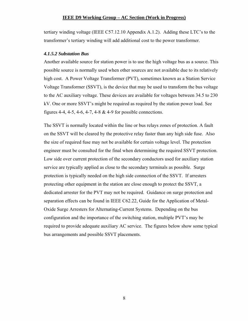
4.1.5.2 Substation Bus
Another available source for station power is to use the high voltage bus as a source. This
possible source is normally used when other sources are not available due to its relatively
high cost. A Power Voltage Transformer (PVT), sometimes known as a Station Service
Voltage Transformer (SSVT), is the device that may be used to transform the bus voltage
to the AC auxiliary voltage. These devices are available for voltages between 34.5 to 230
kV. One or more SSVT’s might be required as required by the station power load. See
figures 4-4, 4-5, 4-6, 4-7, 4-8 & 4-9 for possible connections.
The SSVT is normally located within the line or bus relays zones of protection. A fault
on the SSVT will be cleared by the protective relay faster than any high side fuse. Also
the size of required fuse may not be available for certain voltage level. The protection
engineer must be consulted for the final when determining the required SSVT protection.
Low side over current protection of the secondary conductors used for auxiliary station
service are typically applied as close to the secondary terminals as possible. Surge
protection is typically needed on the high side connection of the SSVT. If arresters
protecting other equipment in the station are close enough to protect the SSVT, a
dedicated arrester for the PVT may not be required. Guidance on surge protection and
separation effects can be found in IEEE C62.22, Guide for the Application of Metal-
Oxide Surge Arresters for Alternating-Current Systems. Depending on the bus
configuration and the importance of the switching station, multiple PVT’s may be
required to provide adequate auxiliary AC service. The figures below show some typical
bus arrangements and possible SSVT placements.
IEEE D9 Working Group – AC Section (Work in Progress)
9
Figure 4-4: One or more line breakers with no common bus
Figure 4-5: Single bus configuration

IEEE D9 Working Group – AC Section (Work in Progress)
10
Figure 4-6: Ring bus configuration (Install isolation switch in the line where the SSVT is connected if possible.)
Figure 4-7: Breaker-and-a-half configuration

IEEE D9 Working Group – AC Section (Work in Progress)
11
Figure 4-8: Main and Transfer / Z bus configuration
Figure 4-9: Double breaker configuration
Where two station service feeds are provided within the switching station, either both by
bus, or one by bus and the other by some other source, the feeds typically are switched on
the secondary side with either a manual or automatic transfer switch. A typical
arrangement is shown in Figure 4-10.

IEEE D9 Working Group – AC Section (Work in Progress)
12
Figure 4-10: Typical arrangement for two station service sources in a switching station
4.1.5.3 Distribution Line
Distribution feeders may be used as a normal or emergency AC auxiliary power source.
Utilizing the distribution feeder as the normal source can be beneficial if that feeder is not
directly supplied by the utility substation. In that case, the AC auxiliary power source
would still be energized in the event of a de-energized utility substation. The
disadvantage to using a distributor feeder is that the utility substation is depending upon
the reliability of that feeder to supply AC auxiliary power. There is the risk of losing AC
auxiliary power from the distributor feeder even though the utility substation is still
energized.
Some utilities use a distributor feeder as a back-up to a power transformer or bus normal
AC auxiliary supply. There are engineering aspects to consider when using an outside
distribution feeder as an emergency back-up source. When using the distribution feeder
as a back-up source, consideration has to be taken as how to switch between the two
supplies. This is done through a manual or automatic transfer switch. Consideration also
must be given as to whether or not to switch the neutral connections when switching the

IEEE D9 Working Group – AC Section (Work in Progress)
13
live lines. If the distribution feeder has already been transformed to an AC auxiliary
voltage (i.e. 120/240 volt), the neutral has been single point grounded, most likely, at the
transformer secondary connection point. Conversely, the normal AC auxiliary source is
typically single point grounded to the substation ground grid. In that case, it is desirable
to switch the neutral from the normal source to the neutral of the emergency source. If
both neutrals are single point grounded onto the same ground, then it is not necessary to
switch the neutrals of the AC auxiliary supplies.
4.1.5.4 Standby Generators
Generators may also be used as an AC auxiliary power source. In substations, generators
are typically used as an emergency power source instead of a permanent power source.
This is due to the disadvantages of using generators as a permanent AC auxiliary source.
Choosing to use generators as a permanent AC auxiliary source will require additional
design considerations. Fire protection systems will need to be designed to protect the
substation equipment from a generator file. Fuel storage systems will need to be installed
to house the fuel needed to run the generators. The generators may also be housed in a
separate building structure, which requires the installation of a ventilation system.
Generators used as an emergency AC auxiliary power source have more merit than as a
permanent source. As an emergency source, there is not the same need for fire protection
installation, fuel storage system, or building ventilation (if the generators are located
outdoors in the switchyard).
4.2 Load Requirements AC auxiliary power systems are vital to the successful operation of a substation. The AC
auxiliary system supplies auxiliary AC power to all AC loads located within the substation.
Because of the critical nature of much of these loads, it is necessary to calculate all of the
required AC loads within the substation to adequately design the AC auxiliary power system.
The governing design requirements of the substation AC auxiliary system should be safe, reliable
operation and allowance for future load growth. Some applications may require additional
uninterruptable power supplies.

IEEE D9 Working Group – AC Section (Work in Progress)
14
In both transmission and distribution substations, the substation AC auxiliary systems are
typically used to supply loads such as, but are not limited to:
1. Essential Load
2. Non Essential Load
3. Maintenance Load
4. Construction Load
4.2.1 Essential Load
Provide description –
a) Transformer cooling, oil pumps, and load tap changers
b) Substation battery charging systems
c) Circuit breaker air compressors and charging motors
d) Power circuit breaker control circuits
e) Power equipment heating circuits
f) Communications equipment
g) Relaying, supervisory, alarm, and control equipment
h) AC/DC converter – uninterruptable power supplies
i) AC powered motor operated disconnect switches
4.2.2 Non Essential Load
Provide description –
a) Outdoor lighting, security systems and receptacles
b) Control building or switchgear building lighting, HVAC, and receptacles
4.2.3 Maintenance Load
Provide description –
4.2.4 Construction Load
Provide description –
IEEE D9 Working Group – AC Section (Work in Progress)
15
4.3 One-Line Diagram
The designer may consider the following list when designing one-line diagram. Transformer connection requirements when three-phase transformer is used
Transformer KVA and voltage rating
Possible available sources
Determine preferred sources
Number of AC Panels required
Method of connecting the AC panels to the transformer
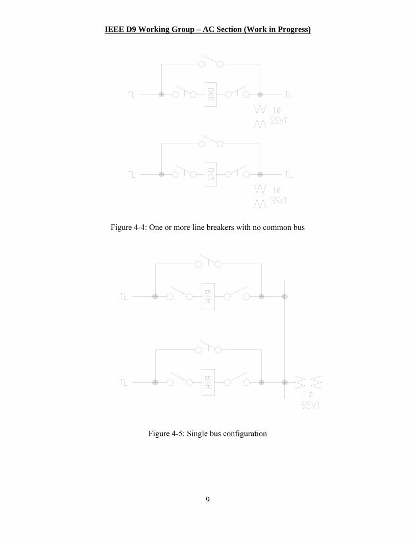
4.3.1 Distribution Substation
A distribution substation AC station service auxiliary system may be as simple as a step
down transformer with secondary voltage to an AC panelboard to distribute service loads.
Depending upon the size and criticality of the distribution substation, an alternate source and
manual or automatic transfer switch may be incorporated.
Provide Samples -
Convert to Block Diagram –
IEEE D9 Working Group – AC Section (Work in Progress)
16
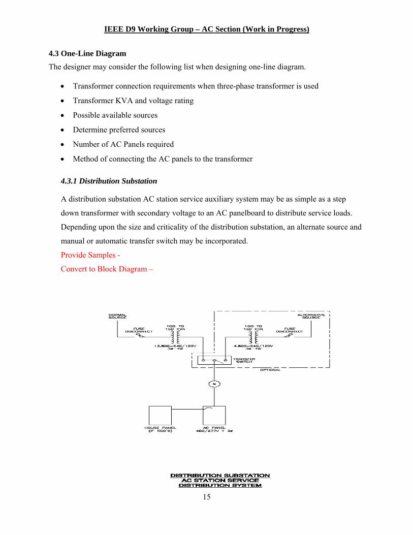
4.3.2 Transmission Substation
The AC station service auxiliary system normally requires a primary and a backup station
service source. Typically, the primary source is fed within the substation from a substation
bus or transformer tertiary. The backup source may also come from a substation bus or
transformer tertiary, or from an external source outside the substation or by a backup
generator. The design should include the most reliable and efficient means for two auxiliary
system sources. The service loads should be fed through an automatic transfer switch to
provide redundancy and reliability to serve the substation AC loads.
Many AC auxiliary systems in transmission substation will include AC panels in the
substation yard to serve outdoor yard equipment and lighting circuits. Depending upon the
voltage, yard equipment may be served from AC panels within the control building. Large
three phase equipment loads may require yard panels rated 480 VAC, which would require
voltage step down for other substation loads. Circuits within the control building should be
served from AC panels within the building.
Provide Samples -
Convert to Block Diagram –

IEEE D9 Working Group – AC Section (Work in Progress)
17
4.4 Operation and Maintenance Considerations
Isolation Switch Requirements Equipment Accessibility Back-up Supply
4.5 Design Considerations
Review & Comment –
The designer may consider the following list when designing an AC system for Substation:
Location of AC equipment indoor/outdoor
Number of AC Panels
Essential loads connections
Non-essential loads connections
Conductor type and size
Voltage drop calculations
NEC requirements
4.6 Selection of auxiliary system voltage
Review & Comment –
Several secondary voltage levels are available for ac auxiliary systems. When determining the
voltage level needed, the designer may use a standard voltage level determined by the designer’s
power system or use a variation to maintain the voltage levels of the equipment being supplied.
Either way, the designer needs to remember the factors in section 4.2: Connected Ultimate Load.
4.7 Transformer Selections
4.7.1 Single-Phase
Single-phase distribution transformers are manufactured with one or two primary bushings.
The single-primary-bushing transformers can be used only on grounded wye systems if they
are properly connected. An example, single-phase transformer connected to a three-phase
2,400-volt L-L to obtain l20-volt single-phase is shown. The connections are the same for
the following voltage levels: 4,800 volt L-L, 7,200 volt L-L, 13,200 volt L-L, and 34,400 volt
L-L.
IEEE D9 Working Group – AC Section (Work in Progress)
18
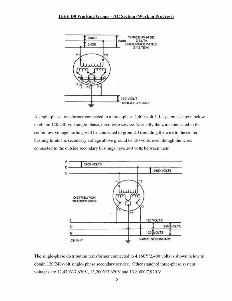
A single-phase transformer connected to a three-phase 2,400-volt L-L system is shown below
to obtain 120/240-volt single-phase, three-wire service. Normally the wire connected to the
center low-voltage bushing will be connected to ground. Grounding the wire to the center
bushing limits the secondary voltage above ground to 120 volts, even though the wires
connected to the outside secondary bushings have 240 volts between them.
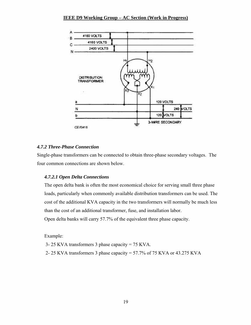
The single-phase distribution transformer connected to 4,160Y/2,400 volts is shown below to
obtain 120/240-volt single- phase secondary service. Other standard three-phase system
voltages are 12,470Y/7,620V, 13,200Y/7,620V and 13,800Y/7,970 V.
IEEE D9 Working Group – AC Section (Work in Progress)
19
4.7.2 Three-Phase Connection
Single-phase transformers can be connected to obtain three-phase secondary voltages. The
four common connections are shown below.
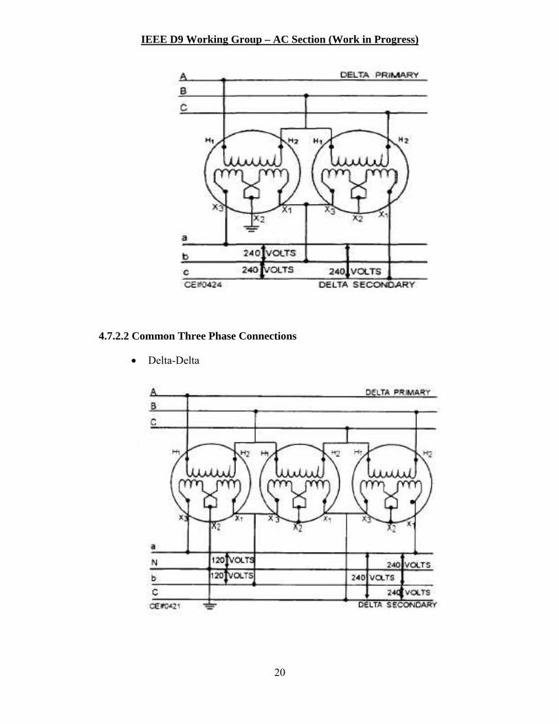
4.7.2.1 Open Delta Connections
The open delta bank is often the most economical choice for serving small three phase
loads, particularly when commonly available distribution transformers can be used. The
cost of the additional KVA capacity in the two transformers will normally be much less
than the cost of an additional transformer, fuse, and installation labor.
Open delta banks will carry 57.7% of the equivalent three phase capacity.
Example:
3- 25 KVA transformers 3 phase capacity = 75 KVA.
2- 25 KVA transformers 3 phase capacity = 57.7% of 75 KVA or 43.275 KVA
IEEE D9 Working Group – AC Section (Work in Progress)
20
4.7.2.2 Common Three Phase Connections
Delta-Delta

IEEE D9 Working Group – AC Section (Work in Progress)
21
Wye-Wye
Delta-Wye or Wye-Delta

IEEE D9 Working Group – AC Section (Work in Progress)
22
4.7.2.3 Personnel Safety
All engineering, construction, and maintenance shall adhere to specific codes and
standards as well as the Owner’s operating policy to ensure personnel safety.
4.7.2.4 Ferroresonance
Ferroresonance is a condition that creates a high voltage between the transformer primary
winding and ground. The high voltage can be as much as five times of the primary
voltage. In such cases the transformer, cables insulation, or other equipment can be
damaged. When present, the transformer will make sounds that are not of its normal
hum.
Ferroresonance occurs under the following conditions
Three phase
Ungrounded primary and transformer grounded
Long primary cable, producing a high capacitance
No load on the bank or lightly loaded
4.8 Station Power Transformer Types and Ratings In this section the following transformer requirements will be considered: 4.8.1 Number of the transformer selection
Station load dictate the number of transformers that must be used for station service
transformer. For substations with single-phase and light to medium loads, single-phase
transformer is used. For substations with three-phase high loads, a three transformer is
normally selected. Other loads such as maintenance equipment may dictate the number of
transformers to be used for station power.
4.8.2 Station Power Transformer Ratings
The capacity of a transformer is determined by the amount of current it can carry
continuously at rated voltage without exceeding the design temperature. Transformer rating
is given in kilovolt-amperes (kVA) since the capacity is limited by the load current which is
proportional to the kVA regardless of the power factor. The standard kVA ratings are given
in Table 4-1 below.

IEEE D9 Working Group – AC Section (Work in Progress)
23
Table 4-1: Standard Ratings of Distribution Transformer kVA
Overhead Type Pad Mounted Type Single Phase
Three Phase
Single Phase Three Phase
5 15 25 75 10 30 37.5 112.5 15 45 50 150 25 75 75 225
37.5 112.5 100 300 50 150 167 500 75 225 750 100 300 1000 167 500 1500 250 2000 333 2500 500
4.8.3 Transformer Impedance
4.8.4 Transformer Connections Depending on number of transformer selected for station power applications two types of connections are employed: 4.8.4 .1 Single Phase Transformer Application
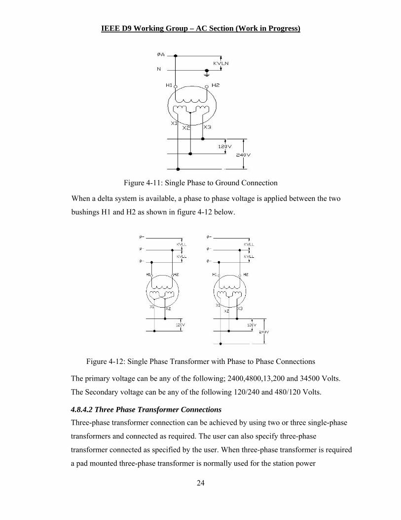
Single-phase distribution transformers are manufactured with one or two primary
bushings. The single-primary-bushing transformers can be used only on grounded wye
systems. For this connection the H1 bushing is connected to one of the available phases
while the other bushing is connected to ground as shown in figure 4-11 below.
IEEE D9 Working Group – AC Section (Work in Progress)
24
Figure 4-11: Single Phase to Ground Connection
When a delta system is available, a phase to phase voltage is applied between the two
bushings H1 and H2 as shown in figure 4-12 below.
Figure 4-12: Single Phase Transformer with Phase to Phase Connections
The primary voltage can be any of the following; 2400,4800,13,200 and 34500 Volts.
The Secondary voltage can be any of the following 120/240 and 480/120 Volts.
4.8.4.2 Three Phase Transformer Connections
Three-phase transformer connection can be achieved by using two or three single-phase
transformers and connected as required. The user can also specify three-phase
transformer connected as specified by the user. When three-phase transformer is required
a pad mounted three-phase transformer is normally used for the station power

IEEE D9 Working Group – AC Section (Work in Progress)
25
applications. A pad mounted three-phase transformer is applicable to below grade
connection from both the primary and the secondary’s sides.
When selecting a three-phase transformer the following must be considered before
selecting the transformer connection:
The required secondary voltage
Safety
Ferro resonance condition
4.8.4.3 Secondary Voltage
The following secondary Transformer connection must be selected in order to obtain the
secondary voltage that will be required for the application
4.9 Transfer Switch
4.9.1 General
The need for an auxiliary power system transfer switch is related to the criticality of the
substation. If only one station service power source is available, a transfer switch may not be
required. If there are no critical AC system requirements, the DC battery system may be
sufficient to operate the critical DC systems until the AC station service power is restored.
Most substations are provided with two sources of station service AC power. The two
sources of station service power are generally designated as the primary source and the
alternate (or backup or secondary) source. Both sources should be of equal reliability.
To simplify the operation of the transfer between sources, a “break before make” operation is
suggested. This will ensure that sources that are out of phase with one another do not operate
in parallel. In the case of manual operation of the transfer switch, it may be desirable to
disable or lock out one source while the other source is being used. In both cases, sufficient
training should be provided to operators to ensure that sources are not paralleled.
Since the auxiliary power sources can be supplied at different voltages than the utilization
voltage in the substation, the transfer switch can be applied at either the primary or secondary
voltage. The higher voltage application results in lower current rated equipment. 13.8kV,
12.47kV, 4.16kV, 480V and 240/120V are common auxiliary power voltages and the transfer
IEEE D9 Working Group – AC Section (Work in Progress)
26
switch can be applied at any of these voltages. The auxiliary power source can be either
three-phase or single-phase depending on the station service requirements. Transfer switches
typically can be purchased with two, three or four poles. A four pole switch has the ability to
switch the neutral and is necessary on a system that has separately derived system.
Smaller rated transfer switches can be wall mounted. Floor mounted switches are common.
Transfer switches can be purchased for indoor or outdoor mounting.
The transfer switch may be as simple as two input sources with switching devices and one
output to the load. The transfer system may be as elaborate as an unit switchgear consisting
of two input switching devices, two transformers, two main circuit breakers, one tie circuit
breaker and multiple branch circuit breakers.
Another consideration when designing the transfer system is the reliability of the transfer
switch. It may be prudent to make provisions to bypass the switch in the event of the switch’s
failure, maintenance or replacement. This may be accomplished by having a third source
routed to the substation AC load center that is left normally open and locked out until it is
needed. It may be more cost effective to route another set of conductors from either or both
of the primary and alternate source to the substation AC load center. Similar to the transfer
operation, training and procedure should be provided to the operator so that it will be
unlikely to parallel sources for a bypass option.
4.9.2 Manual Transfer Switch
For less critical substations a manual transfer switch will provide the capability of
transferring from the primary to the alternate source. The manual transfer switch will be a
much simpler and lower cost switch than an automatic transfer switch. However, the use of
the manual transfer switch will require station alarms to alert operations personnel of the loss
of the primary source and dispatching personnel to the substation to operate the manual
Figure 4.9-1 Simple Transfer switch
Figure 4.9-2 Complex Transfer System

IEEE D9 Working Group – AC Section (Work in Progress)
27
transfer switch. Proper design of the DC battery system is required to provide continuous
operation of critical systems (system protection functions, control and breaker tripping) while
personnel responds and manually operates the transfer switch.
If the substation has only one source of AC power, a manual transfer switch may still be
desirable as a connection point for a temporary AC alternate source, such as a portable
generator.
The manual transfer switch consists of two (2) manually operated switching devices (usually
circuit breakers) capable of interrupting the load current of the transfer switch. The two
switching devices are typically mechanically interlocked to prevent both AC sources from
being connected in parallel. Fault current interruption capability is not required in the transfer
switch, but could be included or provided separately. Indication of source status (hot or
dead) is not typically provided. Some point of alarm is necessary to detect the loss of the
primary AC source.
4.9.3 Automatic Transfer Switch
Critical substations or substations with critical AC loads will require a transfer switch that
will automatically transfer from the primary source to the alternate source when the primary
source is lost.
Transfer should occur under the following conditions:
1) There should be a time delay on loss of the primary source. This is to prevent transfer
for momentary problems with the primary source.
2) The alternate source is available. This is to prevent transfer to a dead source.
Automatic return to the primary source should occur only after the primary source has been
restored for a specified time period to prevent return to an unstable source.
The automatic transfer switch consists of two (2) electrically operated switching devices
(usually circuit breakers) capable of interrupting the load current of the transfer switch. The
two switching devices can be electrically and/or mechanically interlocked to prevent both AC
sources from being connected in parallel. Fault current interruption capability is not required
in the transfer switch, but could be provided or added separately. Detection and indication of
IEEE D9 Working Group – AC Section (Work in Progress)
28
source status (hot or dead) is required. Time delays and control sequencing is necessary to
prevent transferring to a dead alternate source or to prevent nuisance transferring to unstable
sources. Indicating lights and relays are usually provided. Alarm indication of transfer should
be provided. Close and latch capability must also be consider in equipment rating.
4.9.4 Alternate Methods
If both sources are designated as primary sources, the AC load can be divided between the
two sources with the transfer switch system consisting of the two normally closed primary
circuit breakers and a normally open transfer circuit breaker.
4.10 AC Panels Review and Comment -
4.10.1 Present and Future Load Accommodation
The number of branch circuits is dependent on the ultimate station build out. The station
arrangement drawing should provide the number of each type of equipment (transformers,
circuit breakers, etc,). The voltage and current requirements of each piece of equipment will
determine the branch circuit breaker rating requirements. For future equipment installations,
the requirements should be a worst case estimation. Allowance for future “unknowns” or
spare branch circuit breakers should be provided.
4.10.2 Load Classification (or Segregation)
It may be desirable to separate critical loads to different AC panels. Non-critical loads
can be connected to different panels from the critical loads.
4.10.3 Number of Panels required
The number of panels will depend on several items;
1) Voltage and phase requirements - Generally, the higher the voltage of the auxiliary
power system, the fewer circuit breakers that can fit in the panel. Two and three pole
circuit breakers will require more space within the panel
2) Load classification - With critical AC loads, additional panels may be required to
allow for segregating the loads
IEEE D9 Working Group – AC Section (Work in Progress)
29
3) Equipment location in the station - If the substation is large, additional panels
installed to serve specific groupings of equipment may be desirable. This will reduce
the length of the branch circuit runs.
4) Number of branch circuits required - Provision for future additions and unplanned
additions should be made. If extensive future development is foreseen, it may be
better to plan on providing some of the future development requirements with the
addition of future panels.
4.10.4 Panel Rating
1) Voltage
2) Main Breaker
3) Branch Breakers
4) Neutral Bus
5) Ground Bus
4.11 Conductor Selection This section covers both the primary and secondary conductors. The primary conductor can be either a bare conductor or insulated cable depending in the location of the transformer. When the transformer is located near the source, a bare conductor either AA or copper can be used. When the transformer is located away from the source, Insulated cable Copper or All Aluminum can be used. The cable is normally installed inside a conduit and buried below grade. Insulated cable is normally used for the secondary conductor. The following must be considered
when selecting either the primary or the secondary conductor. There are three main requirements
for the conductor used for the auxiliary power system. IEEE 525 provides information on the
selection and application of cables and conductor for AC auxiliary power systems.
4.11.1 Cable Insulation Voltage Rating
The cable insulation voltage rating is selected based on the phase to phase operating voltage
and the expected clearing fault clearing time. In general, for a clearing time equal to 1
minute, 100% insulation is selected, for fault clearing time greater than one minute but less
than one hour, 133% insulation is selected. In either case, the protective relays must clear the
fault before the insulation can be damaged as calculated in the sections below. The primary
IEEE D9 Working Group – AC Section (Work in Progress)
30
cable standard voltages are 5, 8,15,25,28 and 35kV. The secondary cable insulating is
normally given in two ratings; 600V or 1000V.
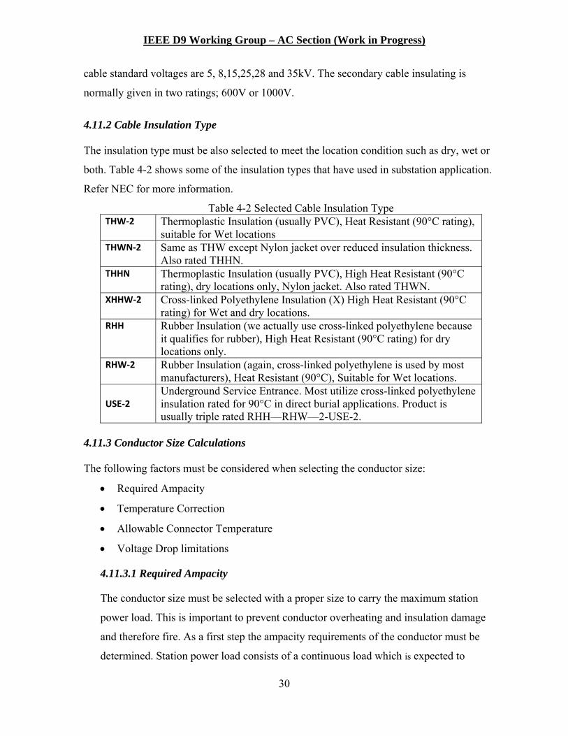
4.11.2 Cable Insulation Type
The insulation type must be also selected to meet the location condition such as dry, wet or
both. Table 4-2 shows some of the insulation types that have used in substation application.
Refer NEC for more information.
Table 4-2 Selected Cable Insulation Type THW‐2 Thermoplastic Insulation (usually PVC), Heat Resistant (90°C rating),
suitable for Wet locations THWN‐2 Same as THW except Nylon jacket over reduced insulation thickness.
Also rated THHN. THHN Thermoplastic Insulation (usually PVC), High Heat Resistant (90°C
rating), dry locations only, Nylon jacket. Also rated THWN. XHHW‐2 Cross-linked Polyethylene Insulation (X) High Heat Resistant (90°C
rating) for Wet and dry locations. RHH Rubber Insulation (we actually use cross-linked polyethylene because
it qualifies for rubber), High Heat Resistant (90°C rating) for dry locations only.
RHW‐2 Rubber Insulation (again, cross-linked polyethylene is used by most manufacturers), Heat Resistant (90°C), Suitable for Wet locations.
USE‐2 Underground Service Entrance. Most utilize cross-linked polyethylene insulation rated for 90°C in direct burial applications. Product is usually triple rated RHH—RHW—2-USE-2.
4.11.3 Conductor Size Calculations
The following factors must be considered when selecting the conductor size:
Required Ampacity
Temperature Correction
Allowable Connector Temperature
Voltage Drop limitations
4.11.3.1 Required Ampacity
The conductor size must be selected with a proper size to carry the maximum station
power load. This is important to prevent conductor overheating and insulation damage
and therefore fire. As a first step the ampacity requirements of the conductor must be
determined. Station power load consists of a continuous load which is expected to

IEEE D9 Working Group – AC Section (Work in Progress)
31
continue for 3 hours or more. The non-continuous load is expected continue for short
time only. The following substation load can be classified as continuous load:
Control Building Air condition load
Transformer cooling loads
Lighting load
Battery Charger load
Load that is non-continuous can be identified as follows:
Breaker motor load
Test equipment load
Motor operator load.
Branch conductors should be sized to meet equipment load requirements. An overload
factor of 1.25 should be applied. Equipment rating data will provide the load
requirements. Some loads are of short duration, such as breaker spring or compressor
motors. Others are continuous duration, such as heaters and transformer fans. As loads
are aggregated at panels the conductors supplying the panel can be sized using a load
factor based on the anticipated coincidence the of branch loads.
Once the continuous and non-continuous load is determined, the primary and secondary
conductors required size can be determined as discussed below:
4.11.3.1.1 Primary Conductor
According the NEC 215.15 (B1) the rating of the conductor shall be selected to
equal to at least the KVA rating of the transformer. Since the station power
primary current is normally low due to transformer low kVA rating and the high
primary voltage, the conductor size is normally selected to exceed the NEC
requirements. Therefore no overheating will occur and the voltage drop is
acceptable. When an insulated cable is used, considerations must be given to the
conductor strength in order to prevent breakage and damage during pulling.

IEEE D9 Working Group – AC Section (Work in Progress)
32
4.11.3.1.2 Secondary Conductor
For secondary conductors rated 600V or less, the NEC requires the conductor be
rated equal to the non-continuous load plus 125% of the continuous load as
defined in section 4.3.4.1 above. Using the NEC appropriate ampacity tables, a
preliminary conductor size can be selected.
4.11.3.2 Temperature Corrections
If the ambient temperature at the substation location is different than the ambient
temperature used for calculating the NEC ampacity tables, the selected conductor
ampacity should be corrected for the new ambient temperature. The following equation
can be used to calculate the ampacity rating of the conductor based on the new ambient
temperature:
4-1
Where: I' = ampacity corrected for ambient temperature I = ampacity shown in the tables Tc = temperature rating of conductor (°C) Ta' = new ambient temperature (°C) Ta = ambient temperature used in the table (°C)
4.11.3.3 Correction for number of conductors
When more than three current carrying conductors either single or multi conductor cables
are used for station power, the conductor rating should be de-rated according to NEC
table 310.15(B)(3)(a) is shown below as table 4-2

IEEE D9 Working Group – AC Section (Work in Progress)
33
Table 4-2 (NEC Table 310.15(B)(3)(1) Adjustment Factors for More Than
Three Current-Carrying Conductors in a Raceway or Cable Number of
Conductors1 Percent of Values in
Table 310.15(B)(16) through Table 310.15(B)(19) as Adjusted for Ambient
Temperature if Necessary 4-6 .80 7-9 .70
10-20 .50 21-30 .45 31-40 .40
41 and Above .35
4.11.3.4 Voltage Drop Verifications
The voltage for both the primary and secondary conductors must be maintained at low
values. For station power applications, the voltage drop is normally low for the primary
conductors and is not an issue. For the secondary conductors, depending on the distance
between the transformer and AC panel must be maintained. Voltage drop limits may be
given either as a target percent drop (typically 3% for a branch circuit or 5% including
the feeder) or as the equipment voltage limitations. In substations with long cable lengths,
the voltage drop considerations may require a larger conductor size than the ampacity
requirements.
4.12 Circuit Protection The protection of AC auxiliary power systems is vital to the successful operation of the
substation. AC auxiliary power system circuit protection is necessary to ensure the proper
protective device coordination operation of the system. This ensures proper clearing of faults in
the AC auxiliary power system.
4.12.1 Available Short Circuit Current
The available short circuit current in AC auxiliary power systems is largely determined by
the AC auxiliary power system station service transformer. The VA rating, transformer
impedance, and voltage rating are the key components in calculating the available short
circuit current.

IEEE D9 Working Group – AC Section (Work in Progress)
34
For single phase AC auxiliary systems, the maximum available short circuit current available
at the transformer secondary bushings is calculated by:
Where, Isc = Maximum available short circuit current VA = Volt Ampere rating of the station service transformer V = Voltage rating of the AC auxiliary power system Zxfmr = Per Unit Impedance of the station service transformer
For three phase AC auxiliary systems, the maximum available short circuit current available
at the transformer secondary bushings is calculated by:
AC auxiliary power system cabling adds extra impedance into the system so that the
maximum available short circuit current seen at the station transformer secondary bushings is
not necessarily the maximum short circuit current that is seen at AC auxiliary distribution
panelboards or end use equipment. The short circuit current at any point downstream from
the station service transformer can be calculated by adding the impedance of the conductor to
the impedance of the transformer on a per unit basis.
Where, Zpu = impedance per unit Z = actual impedance Zbase = impedance reference base VAbase = volt ampere reference base (typically the VA rating of the station service transformer)

IEEE D9 Working Group – AC Section (Work in Progress)
35
The per unit impedance added to an auxiliary ac circuit can be calculated by
Where, Ω = Ohms to Neutral per 1000 feet (Values found in NEC Table 9) L = total conductor length
Once the per unit impedance of the circuit length is known, the maximum available short
circuit current available at the end of that length can be calculated by
4.12.2 Fault calculations At the source At the transformer low side At the AC panel
4.12.3 Transformer Protection
4.12.4 Panel Protection
4.12.5 Feeder Protection
4.12.6 Selection of Circuit Breakers
Appropriate circuit breaker selection is important for the protection and fault clearing
coordination of the AC auxiliary power system. There are three important ratings to consider
when properly selecting circuit breakers for AC auxiliary power system protection. These
are the AC voltage rating, maximum AC current interrupting rating and the AC trip rating.
IEEE D9 Working Group – AC Section (Work in Progress)
36
The AC voltage rating of the circuit breaker should be equal to the operating voltage of the
AC auxiliary power system. Typical AC circuit breaker voltage ratings are 120, 120/240,
208Y/120, 240, 277, 347, 480Y/277, 480, 600Y/347, and 600 volts.
The maximum AC current interrupting rating is the maximum AC short circuit current that
an AC circuit breaker can successfully interrupt. The power circuit breakers selected for use
in an AC auxiliary power system must have a maximum AC current interrupting rating equal
to or higher than the actual maximum AC current that the circuit breaker will see during
service to effectively operate. AC auxiliary power system circuit breakers have typical
maximum AC current interrupting ratings of 7.5 kA, 10 kA, 14 kA, 18 kA, 20 kA, 22 kA, 25
kA, 35 kA, 42 kA, 50 kA, 65 kA, 85 kA, 100 kA, 125 kA, 150 kA, and 200 kA.
The AC trip rating is the maximum AC continuous current that an AC circuit breaker will
allow to flow through it. When this rating is exceeded, the circuit breaker will operate. The
maximum AC continuous current required to supply an AC load should be considered when
selecting the AC trip rating of the circuit breaker. Typical AC continuous current trip ratings
range from 10 amps to 6000 amps.
4.12.7 Selection of Circuit Fuses
Appropriate fuse selection is important for the protection and fault clearing coordination of
the AC auxiliary power system. The important ratings to consider when properly selecting
fuses for AC auxiliary power system protection are voltage rating and current rating.
The AC voltage rating of the fuse should be equal to the operating voltage of the AC
auxiliary power system. Typical AC fuse voltage ratings are 125, 250, 300, 480, and 600
volts.
The AC current rating of a fuse is the maximum AC continuous current that an AC fuse will
allow to flow through it. When this rating is exceeded, the fuse will blow, thus opening the
circuit. The maximum AC continuous current required to supply an AC load should be

IEEE D9 Working Group – AC Section (Work in Progress)
37
considered when selecting the AC fuse rating. Typical AC continuous current fuse ratings
range from 1 amp to 6000 amps.
4.13 Equipment Specifications Documents for specifying equipment include the necessary information for manufactures or
suppliers to prepare and submit a firm proposal to furnish the requested equipment. The
equipment specification is usually comprised of both commercial and technical requirements.
The commercial requirements are typically a set of terms and conditions that address how, when
and to whom the proposals are to be returned. Other information included may be legal
considerations such as taxes or liabilities. Commercial requirements will not be discussed in
further detail in this section.
The technical requirements include the description of the necessary performance requirements
for the equipment. The information in the description should include, as needed, the operational
criteria of the equipment related to its design, construction, testing, and shipment.
Subjects that need to be addressed when specifying aux power equipment include voltage/current
levels, service conditions, code requirements/restrictions, delivery dates, delivery/transportation
to site, and temporary storage of equipment.
Designers should be aware that the standard equipment that is offered by suppliers may not meet
the robust requirements needed for some substations. For instance, the size and layout of the
substation may warrant that larger cables be used between equipment. These larger cable sizes
will require larger cable bending space and termination sizes and hence bigger enclosure sizes.
Numerous standards have been written to specify requirements of equipment to be used in AC
auxiliary power systems. These standards cover transformers, surge arresters, transfer switches,
panelboards, medium and low voltage fuses, medium and low voltage circuit breakers, etc.
Some of these standards are:
IEEE C57.12.00 - General Requirements for Liquid-Immersed Distribution, Power, and
Regulating Transformers

IEEE D9 Working Group – AC Section (Work in Progress)
38
IEEE C62.22 - Guide for the Application of Metal-Oxide Arresters for Alternating-Current
Systems
UL 1008 - Transfer Switch Equipment
NEMA PB-2 – Dead front Distribution Switchboards
UL 248 - Low-Voltage Fuses - Parts 1 through 16: General Requirements
UL 489 (NEMA AB 1) - Molded Case Circuit Breakers, Molded Case Switches and Circuit
Breaker Enclosures
UL 891 - Dead-Front Switchboards
UL 991 - Safety Tests for Safety-Related Controls Employing Solid-State Devices
4.13.1 NEMA standard for indoor/outdoor operation
NEMA (National Electrical Manufacturers Association) creates ratings for equipment based
on expected performance. NEMA does not require independent testing to ensure that the
manufacturer is compliant to the standard. Compliance to the standard is up to the
manufacturer.
Standard NEMA 250-2008 describes types of enclosures for electrical equipment up to 1000
volts maximum. NEMA publishes descriptions of their enclosure types for both non-
hazardous and hazardous locations. They also define which enclosure types may be used for
indoor/outdoor use and which enclosure types may be used for indoor use only.
The design engineer should choose the type of enclosure specific to environmental,
atmospheric and site conditions. For example, a NEMA Type 1 enclosure provides a
minimum degree of protection for indoor use in a non-hazardous location while a NEMA
Type 3R enclosure provides a minimum degree of protection for outdoor use in a non-
hazardous location. The degree of protection offered by these types of enclosures may be
sufficient for a particular substation environment.
4.14 AC Panel Bus rating

IEEE D9 Working Group – AC Section (Work in Progress)
39
4.15 Standby Backup AC System The purpose of the standby AC system would be to provide continued AC power to essential
systems for a set period of time after all sources to the auxiliary power system are unavailable.
The essential systems may be defined as the DC power systems that provide the power required
for relaying, control, telemetry, and communications and any AC power needed for breaker
operation.
Factors that may determine the need for a standby backup AC system are the criticality of the
substation, the battery life for the essential systems, and the reliability of the AC sources for the
auxiliary system. If there is a possibility that an event can occur where the minimum time period
to provide DC power will be exceeded, a standby backup AC system may be considered.
The standby backup AC system should be a stand-alone unit that provides power without the
support of the overall electric power system. A manual start for the system will be desirable
considering that telemetry and communications functions may be disabled. Isolation of the
sources to the aux power system is necessary before connecting the standby backup AC system
to prevent inadvertent paralleling.
The standby backup AC system used in substation normally consists of a diesel generator. The
diesel generator is normally used in the substation for one of the following reasons:
1. Used as back up to the primary source, when only one source is available and the
substation requires two redundant AC sources.
2. Used as the third source when two sources are available and the substation requires three
AC sources.
3. Under emergency condition when all the normal AC sources are not available, the stand
by generator is used to restore the system.
When the generator is used as a backup to one or more of normal AC system, the station load can
be transferred to the generator automatically by the use of an automatic transfer switch or by
manual transfer as required.
IEEE D9 Working Group – AC Section (Work in Progress)
40
4.15.1 Standby Generator for System Collapse
In anticipation of a possibility power system collapse, the station power sources will also be lost.
In this case a stand by generator is installed at several predetermined substation will be used to
re-energize the lost power system. The purpose of this generator is to provide the AC power to a
pre-determined substation loads which is defined as essential loads. The essential loads are
summarized below:
1. Breaker Load - The breaker load consists of the charging motor inrush current normally
added for the first breaker and the continuous motor current added for any additional
breakers.
2. Battery charger - One or two battery chargers as applicable must be included as part of
the Generator load.
3. RTU/Relay Load - Any RTU, Relays and control equipment load.
4. Lighting load - Limited lightning both for the control building and the yard should be
included in case the emergency condition occurs during night.
5. Air Condition/ Heating Load - Limited air condition /heating load should be considered
in case generator is required to run for several days during high or low temperature
conditions.
6. Stand by Voltage Rating - The generator voltage is selected based on the load voltage.
References Distribution Transformer Handbook, First Edition http://www.tpub.com/content/construction/14027/css/14027_75.htm Transformer Connections, General Electric October 1951


![DeWind D9 Series English[1]](https://img.pdfslide.us/doc/110x75/552b0b4a4a795963588b4569/dewind-d9-series-english1.jpg)