Embed Size (px)
Citation preview
8/17/2019 ie55103.ppt
http://slidepdf.com/reader/full/ie55103ppt 1/42
PROGRAMMABLE
LOGICCONTROLLERS Richard A. Wysk
IE450 - Manufacturing Systems
8/17/2019 ie55103.ppt
http://slidepdf.com/reader/full/ie55103ppt 2/42
PURPOSE OF Programmable
Logic Controllers (PLCs Initially designed to relace relay logic
!oards
" Se#uence de$ice actuation
" %oordinate acti$ities
Accets inut from a series of s&itches
Sends outut to de$ices or relays
8/17/2019 ie55103.ppt
http://slidepdf.com/reader/full/ie55103ppt 3/42
FUNCTIONS OFCONTROLLERS '( on-off control)
*( se#uential control)
+( feed!ack control) and
4( motion control.
8/17/2019 ie55103.ppt
http://slidepdf.com/reader/full/ie55103ppt 4/42
CONTROL !E"ICES
'( mechanical control - cam) go$ernor) etc.)
*( neumatic control - comressed air)
$al$es) etc.+( electromechanical control - s&itches)
relays) a timer) counters) etc)
4( electronics control - similar toelectromechanical control) e,cet useselectronic s&itches.
5( comuter control.
8/17/2019 ie55103.ppt
http://slidepdf.com/reader/full/ie55103ppt 5/42
PROGRAMMABLE LOGIC
CONTROLLERInvented in 1968 as a substitute for hardwired relay panels.
A digitally oerating electronic aaratus &hich uses a
rogramma!le memory for the internal storage ofinstructions !y imlementing secific functions such as
logic se#uencing) timing) counting) and arithmetic to
control) through digital or analog inutoutut modules)
$arious tyes of machines or rocesses. /he digital
comuter &hich is used to erform the functions of a
rogramma!le controller is considered to !e &ithin this
scoe. E,cluded are drum and other similar mechanical
se#uencing controllers.
National Electrical Manufacturing Association NEMA!
8/17/2019 ie55103.ppt
http://slidepdf.com/reader/full/ie55103ppt 6/42
"EN!ORS
Rock&ell
E1anuc
Schnieder
etc.
8/17/2019 ie55103.ppt
http://slidepdf.com/reader/full/ie55103ppt 7/42
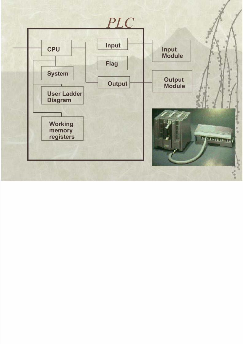
PLC
"#$
%yste&
$ser 'adder (iagra&
)or*ing&e&oryregisters
Input
+lag
,utput
InputModule
,utput
Module
8/17/2019 ie55103.ppt
http://slidepdf.com/reader/full/ie55103ppt 8/42
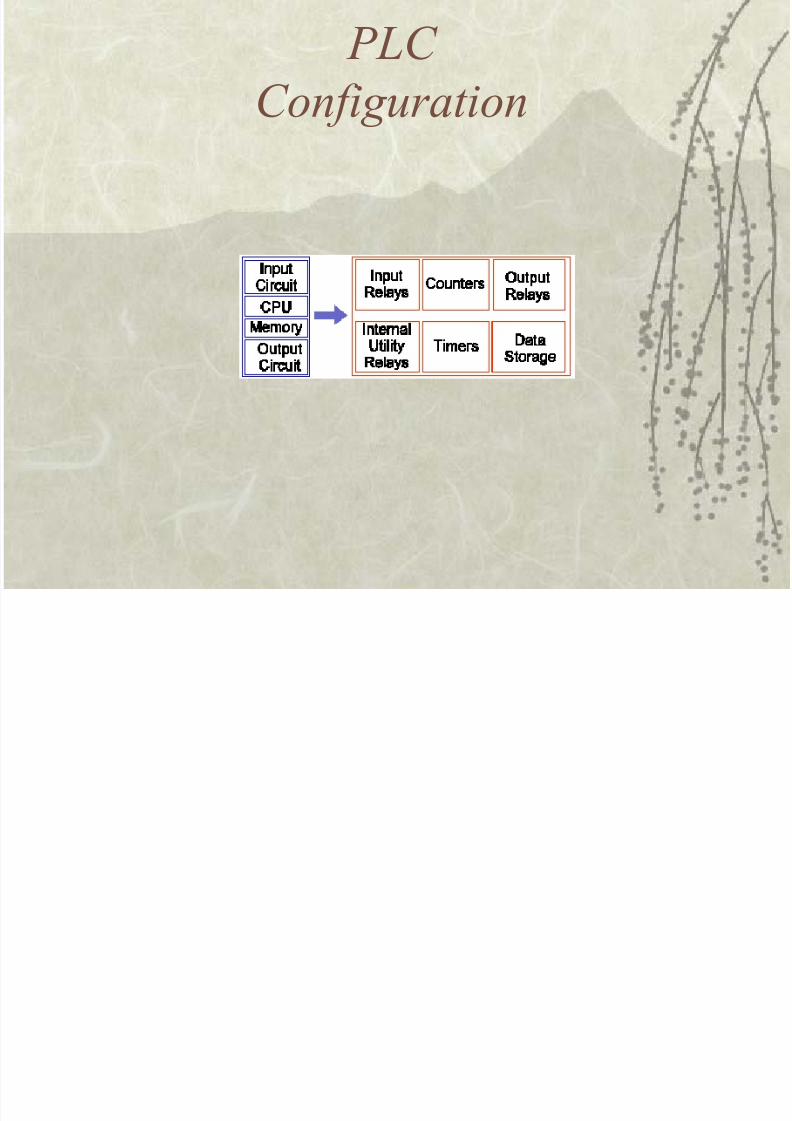
PLC
Con#ig$ration
8/17/2019 ie55103.ppt
http://slidepdf.com/reader/full/ie55103ppt 9/42
%&at 'eices 'oes a PLC interact
)it&*
I23/ REA6S-7contacts(/hese are connected to the outside &orld. /hey hysically e,ist and recei$e signals from s&itches) sensors) etc. /yically theyare not relays !ut rather they are transistors.
I2/ER2A /II/6 REA6S-7contacts( /hese do not recei$e signals fromthe outside &orld nor do they hysically e,ist. /hey are simulated relays andare &hat ena!les a 3% to eliminate e,ternal relays. /here are also somesecial relays that are dedicated to erforming only one task. Some are al&ayson &hile some are al&ays off. Some are on only once during o&er-on and aretyically used for initiali8ing data that &as stored.
%92/ERS-/hese again do not hysically e,ist. /hey are simulated countersand they can !e rogrammed to count ulses. /yically these counters can
count u) do&n or !oth u and do&n. Since they are simulated they are limitedin their counting seed. Some manufacturers also include high-seed countersthat are hard&are !ased. We can think of these as hysically e,isting. Mosttimes these counters can count u) do&n or u and do&n.
8/17/2019 ie55103.ppt
http://slidepdf.com/reader/full/ie55103ppt 10/42
%&at 'eices 'oes a PLC interact
)it&*
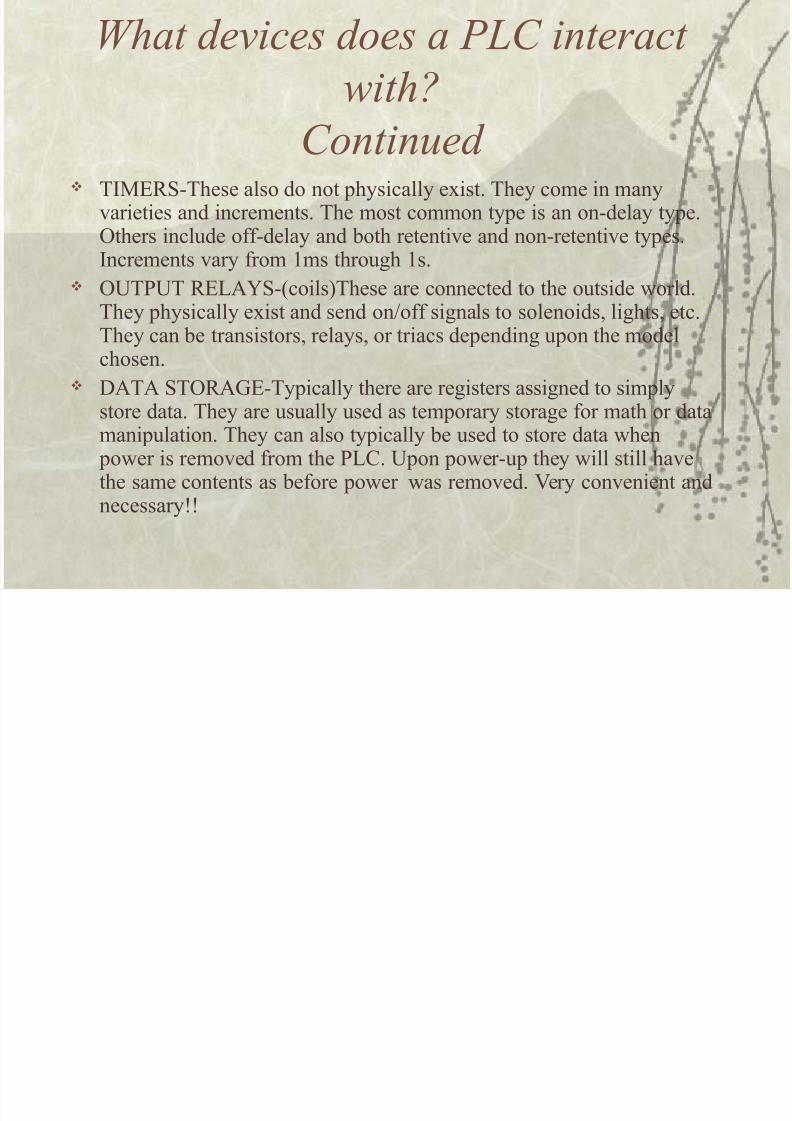
Contin$e' /IMERS-/hese also do not hysically e,ist. /hey come in many
$arieties and increments. /he most common tye is an on-delay tye.9thers include off-delay and !oth retenti$e and non-retenti$e tyes.Increments $ary from 'ms through 's.
9/3/ REA6S-7coils(/hese are connected to the outside &orld./hey hysically e,ist and send onoff signals to solenoids) lights) etc./hey can !e transistors) relays) or triacs deending uon the modelchosen.
:A/A S/9RAE-/yically there are registers assigned to simly
store data. /hey are usually used as temorary storage for math or datamaniulation. /hey can also tyically !e used to store data &hen o&er is remo$ed from the 3%. on o&er-u they &ill still ha$ethe same contents as !efore o&er &as remo$ed. ;ery con$enient andnecessary<<
8/17/2019 ie55103.ppt
http://slidepdf.com/reader/full/ie55103ppt 11/42
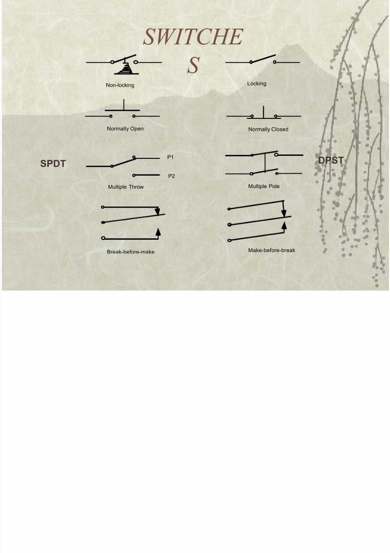
S%ITC+E
S
(#%-%#(-
Non-locking Locking
Normally Open Normally Closed
Multiple Throw
P1
P2
Multiple Pole
Break-e!ore-make Make-e!ore-reak
8/17/2019 ie55103.ppt
http://slidepdf.com/reader/full/ie55103ppt 12/42
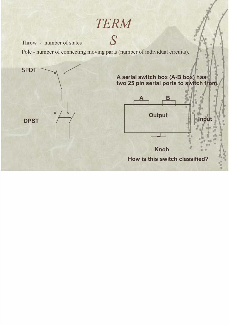
TERM
S /hro& - num!er of states
3ole - num!er of connecting mo$ing arts 7num!er of indi$idual circuits(.
SPDT
(#%-
A serial switch bo A/0 bo! hastwo 2 pin serial ports to switch fro&.
Input
,utput
A 0
3nob
4ow is this switch classified5
8/17/2019 ie55103.ppt
http://slidepdf.com/reader/full/ie55103ppt 13/42
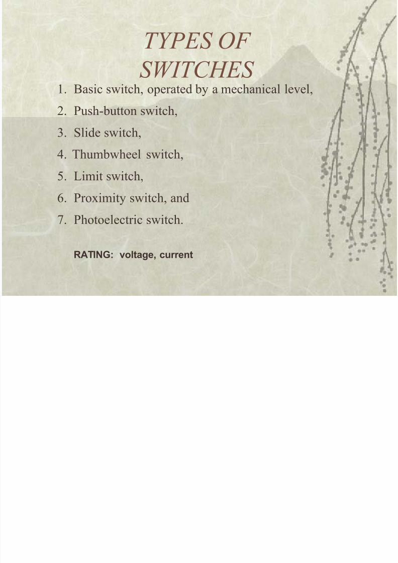
T,PES OF
S%ITC+ES '. =asic s&itch) oerated !y a mechanical le$el)
*. 3ush-!utton s&itch)
+. Slide s&itch)
4. /hum!&heel s&itch)
5. imit s&itch)
>. 3ro,imity s&itch) and
?. 3hotoelectric s&itch.
A-IN7 voltage current
8/17/2019 ie55103.ppt
http://slidepdf.com/reader/full/ie55103ppt 14/42
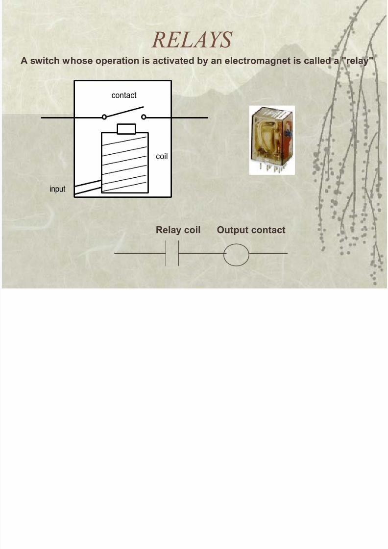
RELA,S A switch whose operation is activated by an electro&agnet is called a :relay:
contact
coil
input
elay coil ,utput contact
8/17/2019 ie55103.ppt
http://slidepdf.com/reader/full/ie55103ppt 15/42
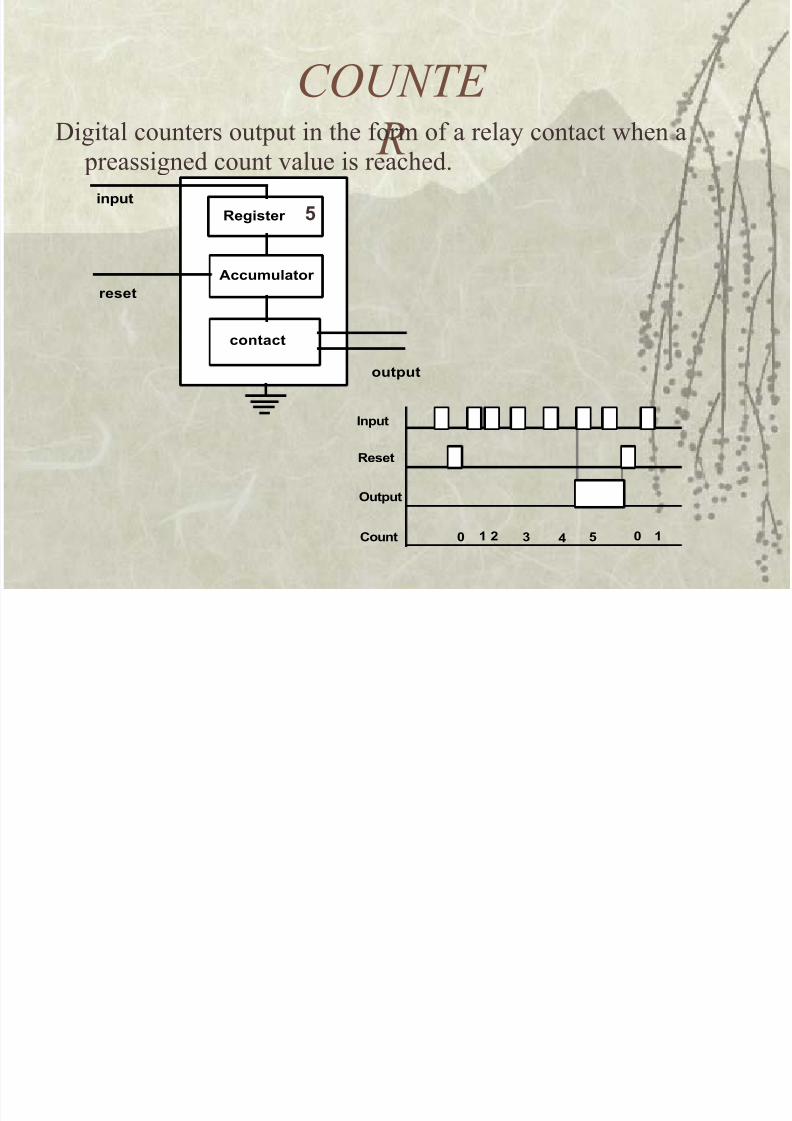
COUNTE
R:igital counters outut in the form of a relay contact &hen a reassigned count $alue is reached.
6egister
Accu&ulator
contact
input
reset
output
Input
6eset
,utput
"ount ; 1 < = 2 ; 1
2
8/17/2019 ie55103.ppt
http://slidepdf.com/reader/full/ie55103ppt 16/42
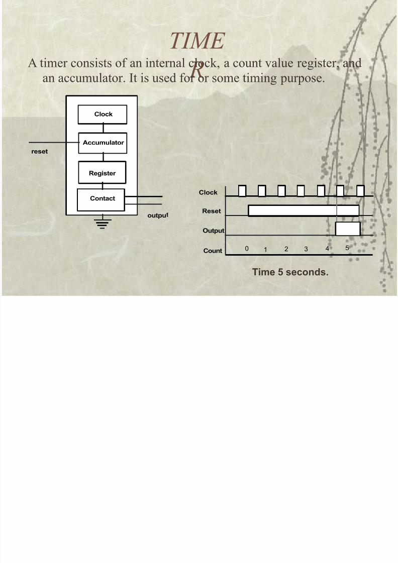
TIME
RA timer consists of an internal clock) a count $alue register) and
an accumulator. It is used for or some timing urose.
"loc*
Accu&ulator
contact
reset
outpu
6egister
"ontact
-i&e 2 seconds.
"loc*
6eset
,utput
"ount 1 2 " #$ %
8/17/2019 ie55103.ppt
http://slidepdf.com/reader/full/ie55103ppt 17/42
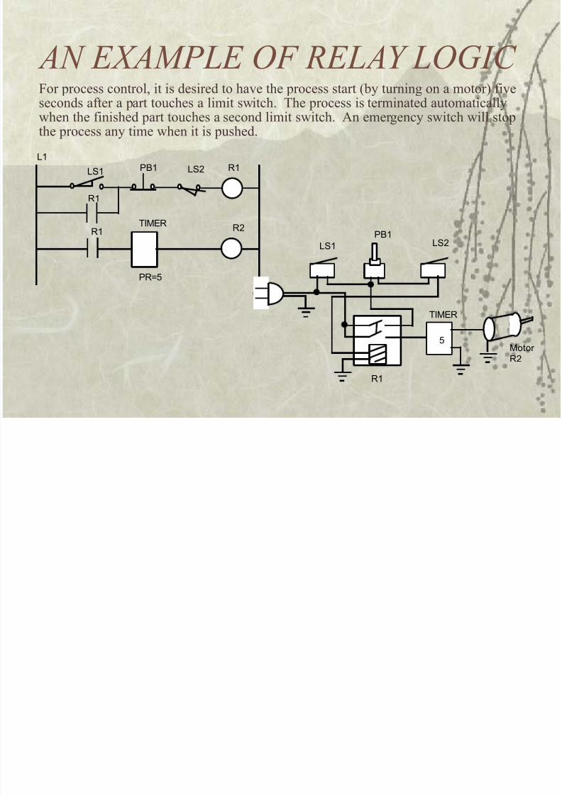
AN E-AMPLE OF RELA, LOGIC
L1
L&1 PB1 L&2 '1
'1
'1T(M)'
'2
P'*%
1or rocess control) it is desired to ha$e the rocess start 7!y turning on a motor( fi$e
seconds after a art touches a limit s&itch. /he rocess is terminated automatically&hen the finished art touches a second limit s&itch. An emergency s&itch &ill stothe rocess any time &hen it is ushed.
L&1
PB1L&2
'1
T(M)'
%Motor'2
8/17/2019 ie55103.ppt
http://slidepdf.com/reader/full/ie55103ppt 18/42
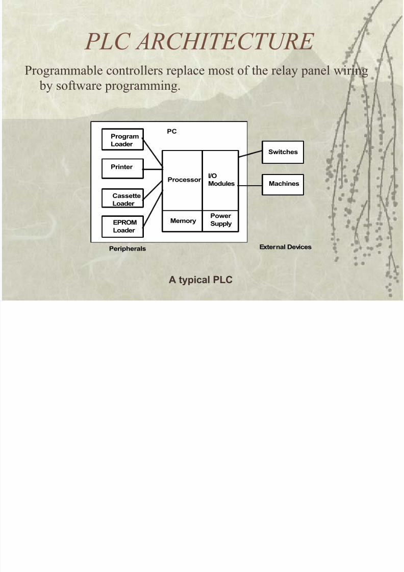
PLC ARC+ITECTURE
3rogramma!le controllers relace most of the relay anel &iring !y soft&are rogramming.
#rocessor I>,
Modules
Me&ory#ower%upply
#rogra&
'oader
#rinter
"assette
'oader
E#6,M
'oader
%witches
Machines
#eripherals E.ternal (evices
#"
A typical #'"
8/17/2019 ie55103.ppt
http://slidepdf.com/reader/full/ie55103ppt 19/42
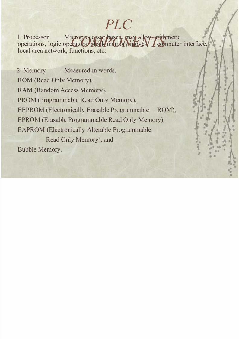
PLC
COMPONENTS '. 3rocessor Microrocessor !ased) may allo& arithmetic
oerations) logic oerators) !lock memory mo$es) comuter interface)local area net&ork) functions) etc.
*. Memory Measured in &ords.
R9M 7Read 9nly Memory()
RAM 7Random Access Memory()
3R9M 73rogramma!le Read 9nly Memory()
EE3R9M 7Electronically Erasa!le 3rogramma!le R9M()
E3R9M 7Erasa!le 3rogramma!le Read 9nly Memory()
EA3R9M 7Electronically Altera!le 3rogramma!le
Read 9nly Memory() and
=u!!le Memory.
PLC
8/17/2019 ie55103.ppt
http://slidepdf.com/reader/full/ie55103ppt 20/42
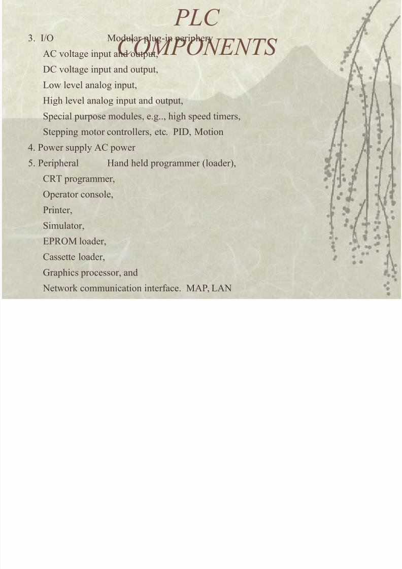
PLC
COMPONENTS +. I9 Modular lug-in erihery
A% $oltage inut and outut)
:% $oltage inut and outut)o& le$el analog inut)
@igh le$el analog inut and outut)
Secial urose modules) e.g..) high seed timers)
Steing motor controllers) etc. 3I:) Motion
4. 3o&er suly A% o&er
5. 3eriheral @and held rogrammer 7loader()
%R/ rogrammer)
9erator console)
3rinter)Simulator)
E3R9M loader)
%assette loader)
rahics rocessor) and
2et&ork communication interface. MA3) A2
8/17/2019 ie55103.ppt
http://slidepdf.com/reader/full/ie55103ppt 21/42
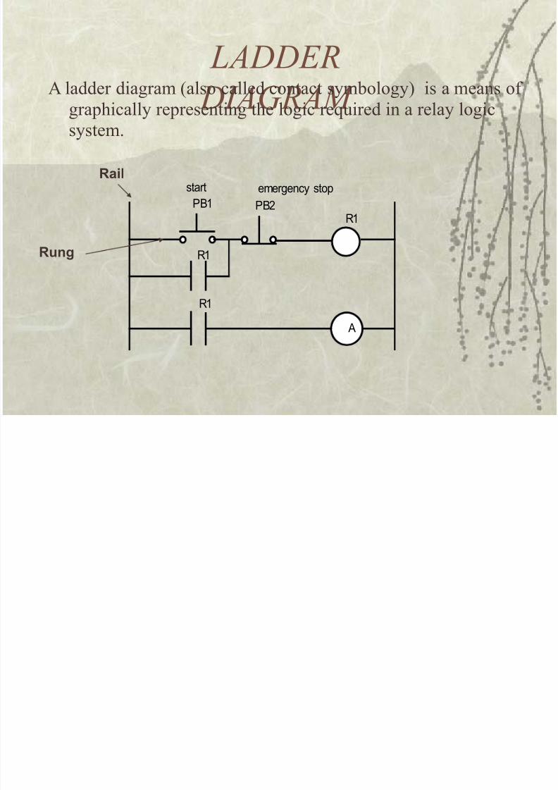
LA!!ER
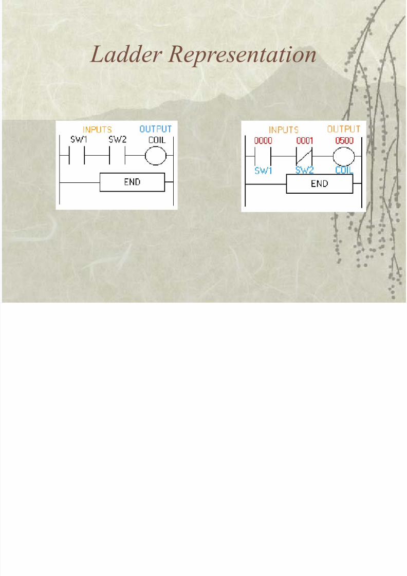
!IAGRAM A ladder diagram 7also called contact sym!ology( is a means of
grahically reresenting the logic re#uired in a relay logic
system.
+
'1
PB1 PB2
'1
'1
start emergency stopail
ung
8/17/2019 ie55103.ppt
http://slidepdf.com/reader/full/ie55103ppt 22/42
La''er Re.resentation
8/17/2019 ie55103.ppt
http://slidepdf.com/reader/full/ie55103ppt 23/42
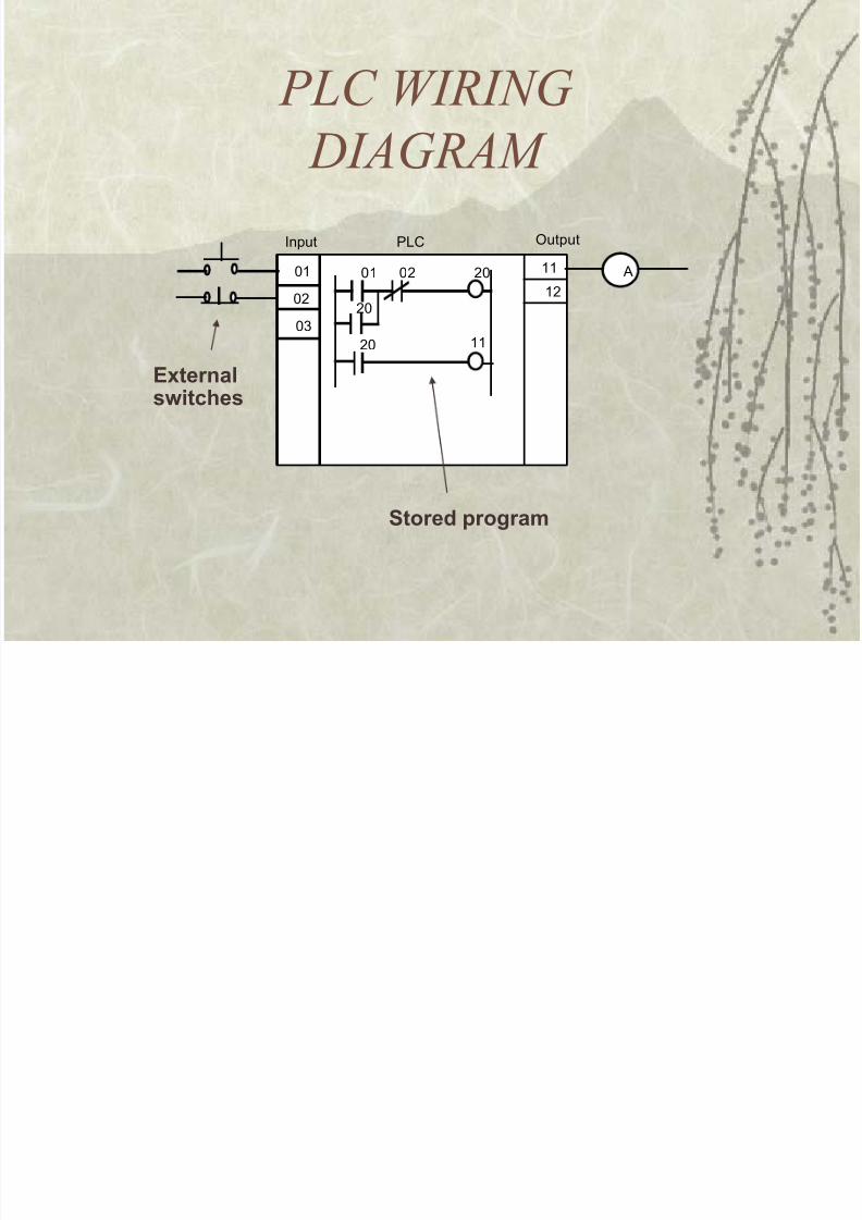
PLC %IRING
!IAGRAM
$1 $2 2$
2$
2$ 11
$1
$2
$"
11
12
+
PLC(nput Output
Eternalswitches
%tored progra&
8/17/2019 ie55103.ppt
http://slidepdf.com/reader/full/ie55103ppt 24/42
SCA
N
begin
Input
,utput
esolvelogic
Idle
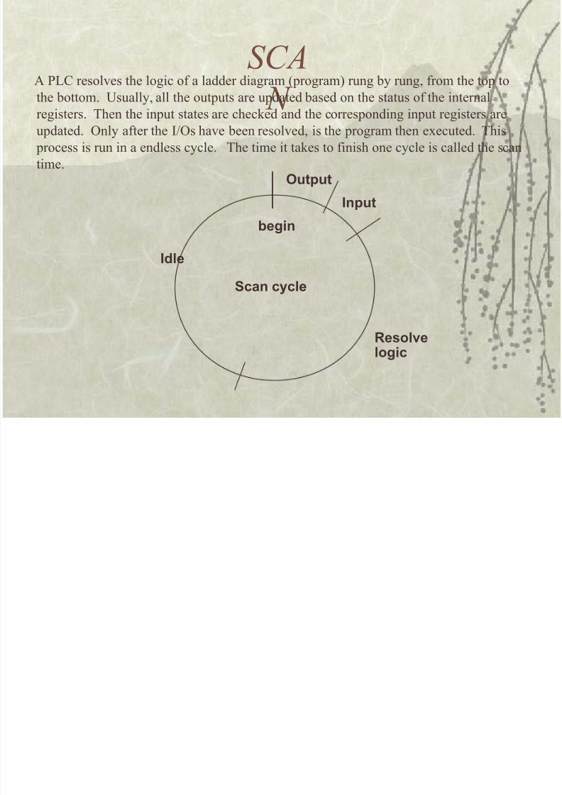
A 3% resol$es the logic of a ladder diagram 7rogram( rung !y rung) from the to to
the !ottom. sually) all the oututs are udated !ased on the status of the internalregisters. /hen the inut states are checked and the corresonding inut registers are
udated. 9nly after the I9s ha$e !een resol$ed) is the rogram then e,ecuted. /his
rocess is run in a endless cycle. /he time it takes to finish one cycle is called the scan
time.
%can cycle
8/17/2019 ie55103.ppt
http://slidepdf.com/reader/full/ie55103ppt 25/42
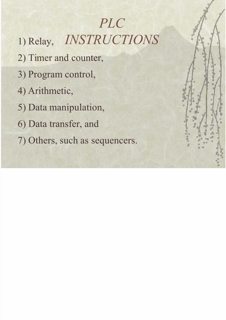
PLC
INSTRUCTIONS '( Relay)
*( /imer and counter)
+( 3rogram control)
4( Arithmetic)
5( :ata maniulation)
>( :ata transfer) and
?( 9thers) such as se#uencers.
8/17/2019 ie55103.ppt
http://slidepdf.com/reader/full/ie55103ppt 26/42
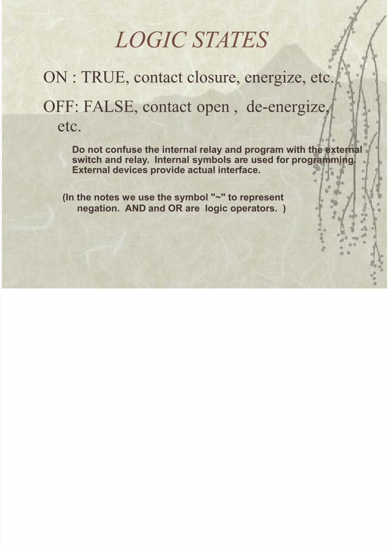
LOGIC STATES
92 /RE) contact closure) energi8e) etc.
911 1ASE) contact oen ) de-energi8e)
etc.
In the notes we use the sy&bol :?: to represent
negation. AN( and , are logic operators. !
(o not confuse the internal relay and progra& with the eternalswitch and relay. Internal sy&bols are used for progra&&ing.Eternal devices provide actual interface.
8/17/2019 ie55103.ppt
http://slidepdf.com/reader/full/ie55103ppt 27/42
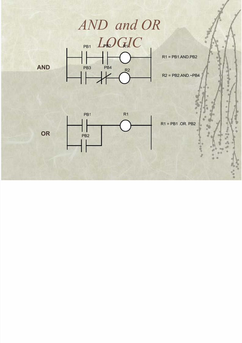
AN! an' OR
LOGIC PB1 '1PB2
'2
'1 * PB1,+N-,PB2
'2 * PB2,+N-,.PB#
PB" PB#
PB1 '1
PB2
'1 * PB1 ,O', PB2
AN(
,
8/17/2019 ie55103.ppt
http://slidepdf.com/reader/full/ie55103ppt 28/42
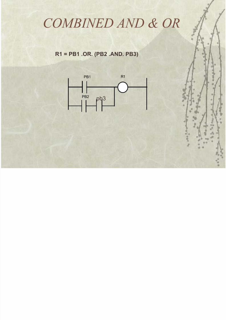
COMBINE! AN! / OR
1 @ #01 .,. #0 .AN(. #0<!
PB1 '1
PB2 p"
8/17/2019 ie55103.ppt
http://slidepdf.com/reader/full/ie55103ppt 29/42
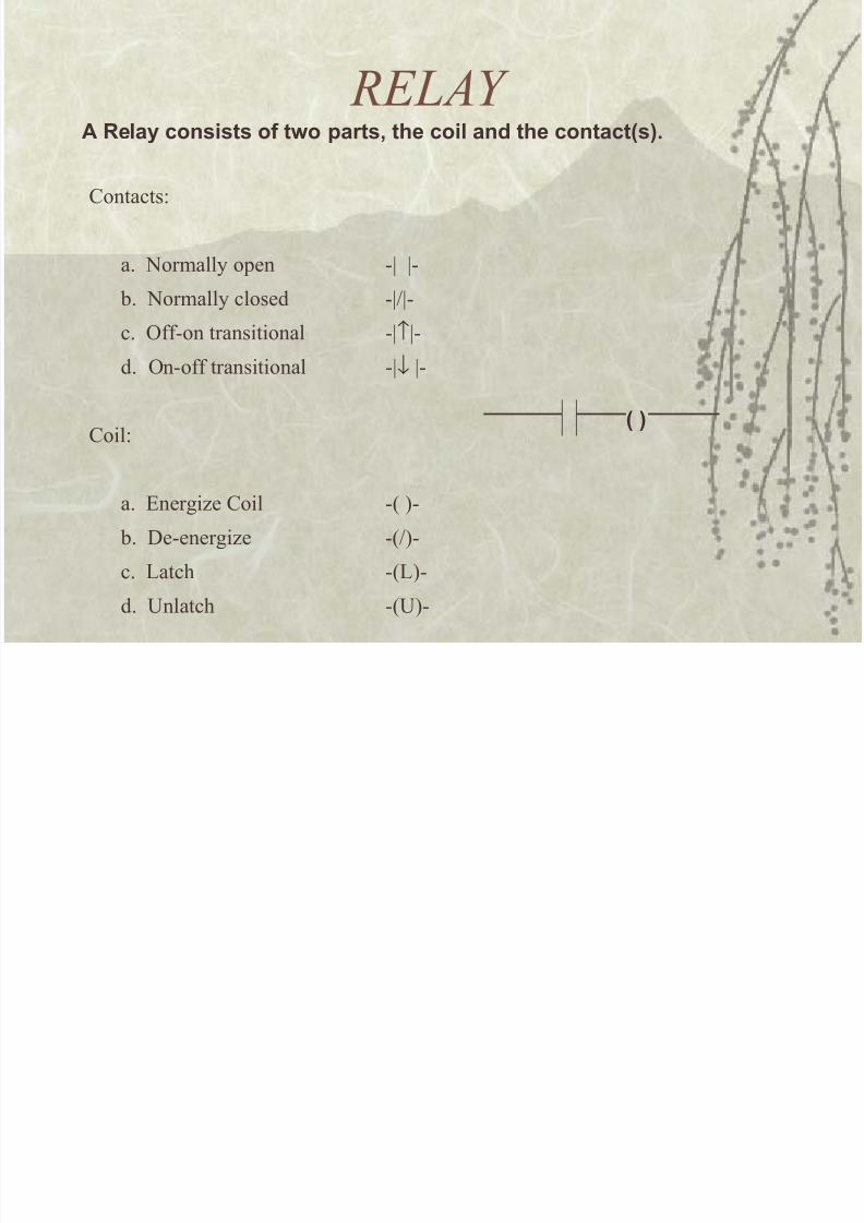
RELA, A elay consists of two parts the coil and the contacts!.
%ontacts
a. 2ormally oen -B B-
!. 2ormally closed -BB-
c. 9ff-on transitional -B↑B-
d. 9n-off transitional -B↓ B-
%oil
a. Energi8e %oil -7 (-
!. :e-energi8e -7(-
c. atch -7(-
d. nlatch -7(-
!
8/17/2019 ie55103.ppt
http://slidepdf.com/reader/full/ie55103ppt 30/42
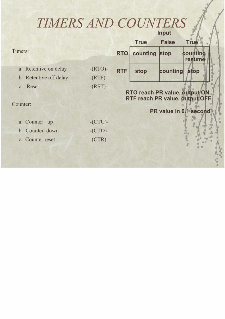
TIMERS AN! COUNTERS
/imers
a. Retenti$e on delay -7R/9(-
!. Retenti$e off delay -7R/1(-
c. Reset -7RS/(-
%ounter
a. %ounter u -7%/(-
!. %ounter do&n -7%/:(-
c. %ounter reset -7%/R(-
-, counting stop countingresu&e
-+ stop counting stop
-rue +alse -rue
Input
-, reach # value output ,N-+ reach # value output ,++
# value in ;.1 second
8/17/2019 ie55103.ppt
http://slidepdf.com/reader/full/ie55103ppt 31/42
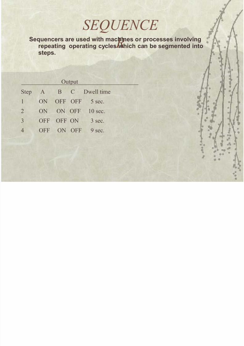
SE0UENCE
R%euencers are used with &achines or processes involving
repeating operating cycles which can be seg&ented intosteps.
9utut
Ste A = % :&ell time
' 92 911 911 5 sec.
* 92 92 911 '0 sec.
+ 911 911 92 + sec.
4 911 92 911 C sec.
8/17/2019 ie55103.ppt
http://slidepdf.com/reader/full/ie55103ppt 32/42
A1B
PLC I9 oints are num!ered) they corresond to the I9 slot on
the 3%.
1or A-= controller used in our la!I9 uses '-+*
Internal relays use 0++ - 0CD
Internal timerscountersse#uencers use C0'-C+*Status C5'-CD*
8/17/2019 ie55103.ppt
http://slidepdf.com/reader/full/ie55103ppt 33/42
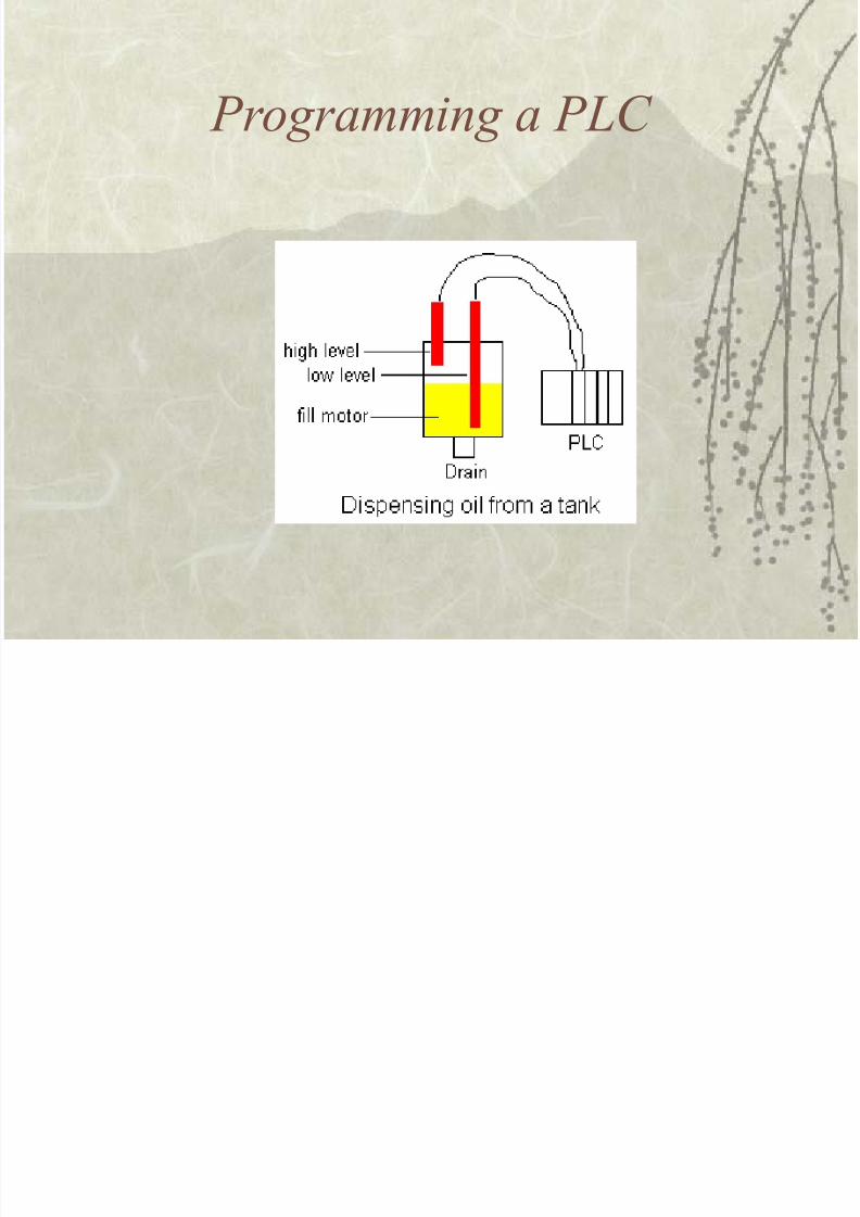
Programming a PLC
8/17/2019 ie55103.ppt
http://slidepdf.com/reader/full/ie55103ppt 34/42
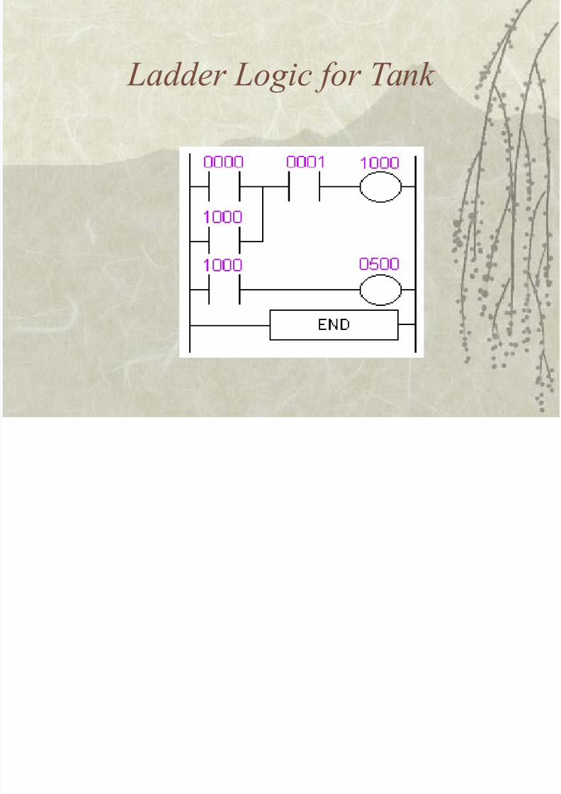
La''er Logic #or Tan2
8/17/2019 ie55103.ppt
http://slidepdf.com/reader/full/ie55103ppt 35/42
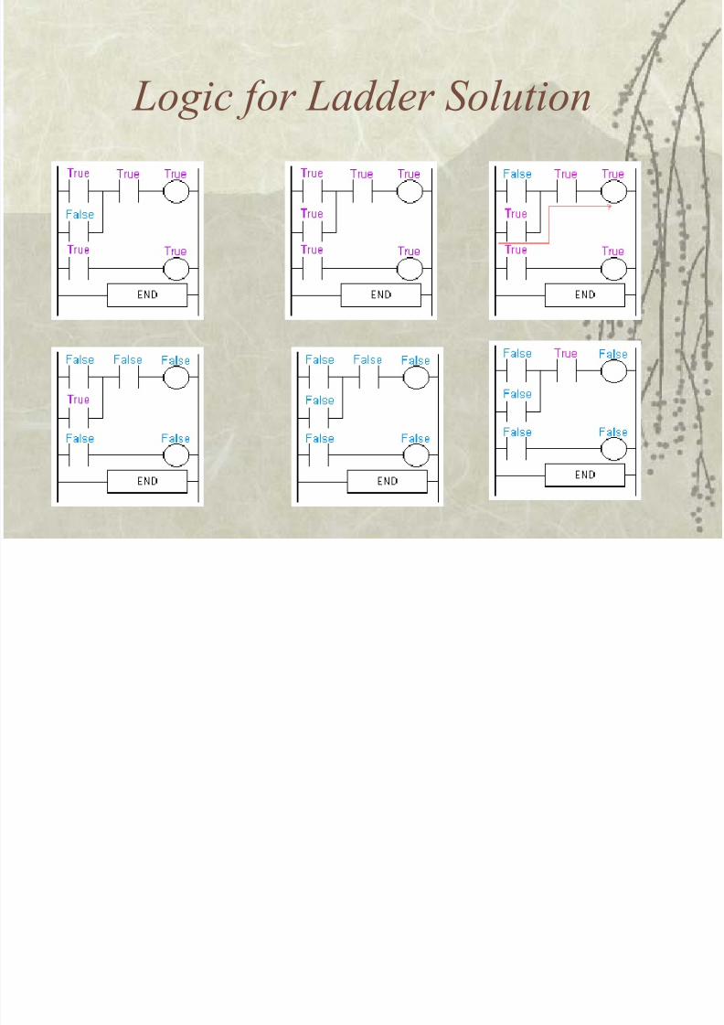
Logic #or La''er Sol$tion
8/17/2019 ie55103.ppt
http://slidepdf.com/reader/full/ie55103ppt 36/42
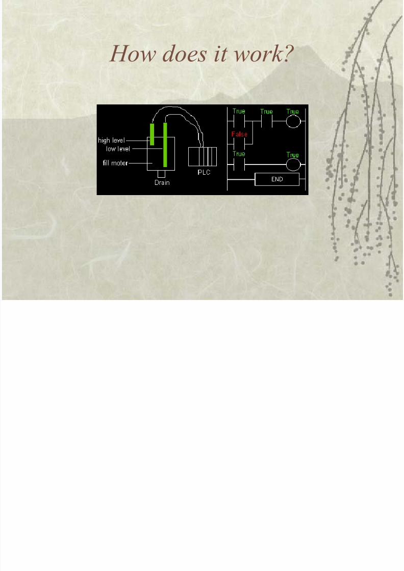
+o) 'oes it )or2*
8/17/2019 ie55103.ppt
http://slidepdf.com/reader/full/ie55103ppt 37/42
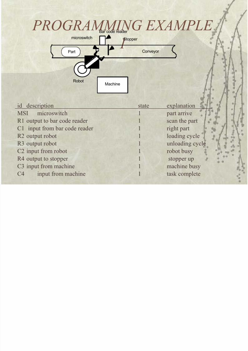
PROGRAMMING E-AMPLE
3Part
microswitch
Bar code reader
&topper
Con/eyor
Machine'oot
id descrition state e,lanation
MSI micros&itch ' art arri$e
R' outut to !ar code reader ' scan the art
%' inut from !ar code reader ' right art
R* outut ro!ot ' loading cycle
R+ outut ro!ot ' unloading cycle
%* inut from ro!ot ' ro!ot !usy
R4 outut to stoer ' stoer u
%+ inut from machine ' machine !usy
%4 inut from machine ' task comlete
8/17/2019 ie55103.ppt
http://slidepdf.com/reader/full/ie55103ppt 38/42
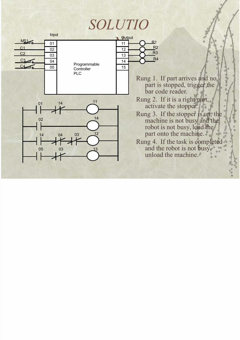
SOLUTIO
N $1$2
$"
$#
$%
1112
1"
1#
1%
(nputOutput
ProgrammaleControllerPLC
M&1
C1
C2
C"
C#
'1
'2
'"
'#
$1 1# 11
$2
1# $# $"
1#
12
1"$% $"
Rung '. If art arri$es and no
art is stoed) trigger the !ar code reader.
Rung *. If it is a right art)acti$ate the stoer.
Rung +. If the stoer is u) themachine is not !usy and the
ro!ot is not !usy) load the art onto the machine.
Rung 4. If the task is comletedand the ro!ot is not !usy)unload the machine.
8/17/2019 ie55103.ppt
http://slidepdf.com/reader/full/ie55103ppt 39/42
8/17/2019 ie55103.ppt
http://slidepdf.com/reader/full/ie55103ppt 40/42
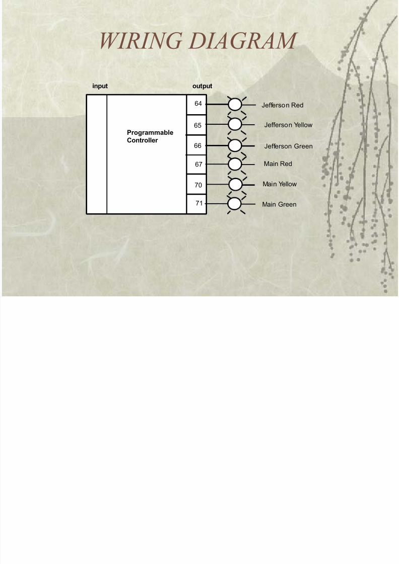
%IRING !IAGRAM
0#
0%
00
0
$
1
#rogra&&able"ontroller
input output
e!!erson 'ed
e!!erson 3ellow
e!!erson 4reen
Main 4reen
Main 3ellow
Main 'ed
8/17/2019 ie55103.ppt
http://slidepdf.com/reader/full/ie55103ppt 41/42
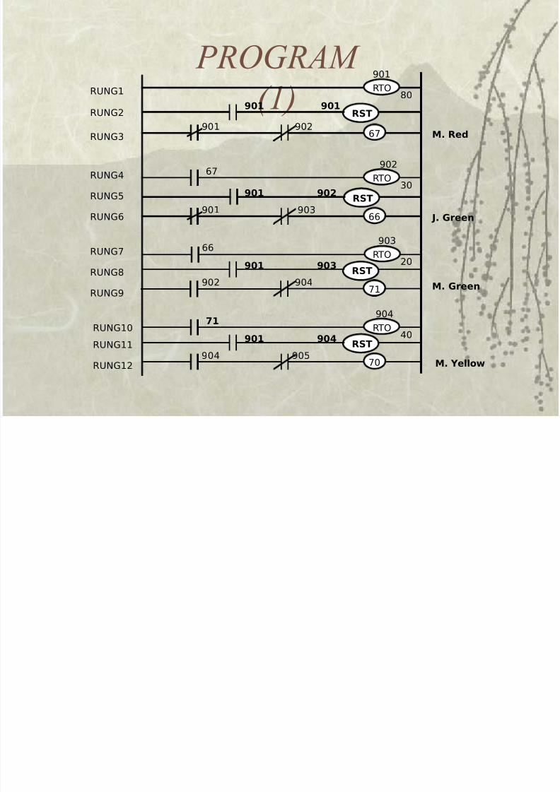
PROGRAM
(3RUNG1
RUNG2
RUNG3
RUNG4
RUNG5
RUNG6
RUNG7
RUNG8
RUNG9
RUNG10
RUNG11
RUNG12
20
67
RTO
903 66
RTO
901
80
RTO
902
30
901 902 67 M. Red
901 903 66 J. Green
902 904 71 M. Green
904 905 70 M. Yellow
RST
RST901 904
RTO
904
40
71
RST901 903
RST901 902
901 901
8/17/2019 ie55103.ppt
http://slidepdf.com/reader/full/ie55103ppt 42/42
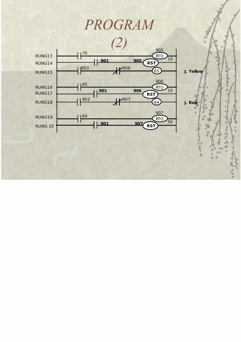
PROGRAM
(4 RUNG13
64RTO
907
50
65
RTO
906
10
70RTO
905
10
903 906 65 J. Yellow
902 64
907 J. Red
RST901 907
RST901 906
RST901 905
RUNG14
RUNG15
RUNG16 RUNG17
RUNG18
RUNG19
RUNG 20