Embed Size (px)
Citation preview

Volume 5 HYDROACOUSTICS
IDENTIFICATION OF THE SHIP'S UNDERWATER NOISE SOURCESIN THE COASTAL REGION
IGNACY GLOZA, STEFAN JAN MALINOWSKI
Naval University ofGdyniaul. Śmidowicza 69,81-103 Gdynia
The results oj the investigations oj underwater noise radiated by ships at thebackground oj the ambient sea noise in the coastal region are presented. Sounds in shallowwater are inherently modified by the local environment. Based on the results oj themeasurements oj both the ambient noise and the noise radiated by ships the investigations ojthe influence oj the ship 's motion on the ambient sea noise were carried out. What more thenoise field at the sea in the coastal region is notably injl.uenced with the technical noise,especially connected with the human 's activity.
lNTRODUCTlON
Much information is required about the local seabed structure to determine accuratelythe acoustic signature of a ship in the shallow water. The radiated ship noise in shallow watercreates a stationary acoustic field. While you examine spectra you must take into accountsome important facts su ch as: sea surface and bottom roughness, water velocity profile, wavepropagation in the sediment, bottom velocity profile and noise source depth; because thestationary acoustic field in a two pIane parallel medium is characterized by the thickness ofthe water and the ref1ectivity of the boundary surfaces. Maxima and minima of pressure aregenerated at some given depths depending on the radiated frequency and distance.
Few detai1ed studies of the underwater radiated noise of surface ships have beenreported, in spite of the fact, that shipping constitutes a main source of noise in the sea."Trends in Merchant Shipping (1969-1980)" by Donald Ross described radiated noise ofmany ships of that period. Sophisticated numerical and experimental research on propellercavitation has been conducted by many researchers in Germany, Poland, Norway and otherEuropean countries in recent years. Propeller noise is a hybrid character of noise having
9

HYDROACOUSTICS Volume 5
features and an origin of both cavitation and hydrodynarnic pressure. Except when the shipsare running at very slow speeds radiated spectra of surface ships are dominated by propellercavitation noise. A main engine noise originates as mechanical vibration of many rotating,unbalanced, and reciprocating parts, ais o repetitive discontinuities, turbulence and cavitationin pipes, valves and pumps and mechanical friction in bearings. A Diesel generate creates 25Hz, 37.5 Hz and a series of harmonics which amplitudes and frequencies are independent ofship speed.
l.SOUND RANGES AND MEASUREMENT CONDITIONS
The measurements were carried out in the Gulf of Puck region and at Naval Test andEvaluation Hydroacoustic Range. The underwater sound measurement was performed bothfor anchored and sailing conditions. Planning was don e to maximize the information from theship noise measurements, because of the high cost of ship's running.
During the ship measurements the ambient noise level was low, the mean wave heightwas less than 0.5 m, and the wind speeds were less than 5 mis. We had the typical summersound speed profile, it means a smooth, regularly decreasing gradient without a mixed layer .
...:iM •••••.
.'/
Fig.l. Plan of ship's field measurement range for running vesselsl-hydrophones, 2 - buoys, 3 - measuring vessel
The ship under test ran at a constant speed and course in order to pass the measurementshydrophones at a know distance. During the run analogue and digital recordings were made,and late subjected to analysis in different frequency bands. Radiated-noise measurementsmust be made at a distance from the radiating vessel, usually from 10 to 100 m.
2. SOURCE LEVEL AND NOlSE SPECTRA
The source levels for radiated noise are suitably spectrum levels relative to the l IlPareference level, and specified in a l Hz band, and mus t be reduced to l m by applying anappropriate spreading or distance correction.
The radiated noise of a ship consists of a mixture of tonal noise having a continuousspectrum and line components happening at discrete frequencies. These two spectral types areillustrated diagrammatically in Fig. 6.
10

Volurne 5 HYDROACOUSTICS
We used for acoustic and vibration measurements real-time digital frequency analyzersand a computer. Suitable used bands are from octave to 1/24-octave and 0.125 Hz narrow-band bandwidth filters. The 0.125 Hz bandwidth was achieved by uniform samplmg of an 8-snoise record at 8192 Hz. This was an advanced acoustic analysis system enables data to beanalyzed on-line so that effects were quickly available. We decided to use such advancedtechniques in order to achieve results as fast as possible.
ł"H:r.łFig.2. The underwater noise spectrogram and spectrum of a moving vessel.
The recordings were carried out by means of the array of hydrophones. On the basis ofthese results we determined the maximum values of the sound pressure levels for differentspeeds of a ship. A sound spectrogram of the radiated ship noise moving away from the arrayof hydrophones in the shallow water shows the parallel lines at low frequencies. Thisfrequency spectrogram is generated by the stationary acoustic field set up in a two planeparallel medium surface and bottom ofthe sea. The hydrophones were located at 12 m .
,.....·..·.· c ..
........... ..... ...~...• ••• ' •• 0 •••••••••••••• L..Time (s)
Fig.3.The sound levels radiated by a moving vessel with different speeds (4 , 6 and 8 knots).
One of the methods of identification of underwater noise of a ship is by investigation ofits spectrum. Basing on the conducted analysis it is possible to isolate discrete components inthe spectra associated with the work of mechanisms and equipment on board along with thebroad band spectrum ref1ecting the work of the cavitating propeller, turbulent flow in pipingand ventilators or bearing frictions. In practice the noise identification is difficult. The ownnoise is combined with technical environmental noise coming from remote shipping, ship-building industry ashore or port works. There exists also the noise of naturalorigin: waves,winds or rainfalls. Additional obstruction in the process of spectral component identificationmay be the fact that various ship's equipment may be the source of hydroacoustic waves ofsimilar or same frequencies. The propeller is the dominant source of the hydroacoustic waves
11

HYDROACOUSTICS Volume 5
at higher vessel speeds. It generates the driving force that is balanced by the resistance forceof the hull. It also stimulates the vibrations of the hull's plating and all elements mounted onit.
Control and evaluation of noise signature is an important determinant of shipsurvivability in a stealthy naval environment. Specialists eonduet vessel triais both staticallyand dynamically, sometimes over their fuli speed ranges. Stationary trials, with ships orsubmarines moored to buoys, enable the acoustic contributions of particular machinerysystems to be estimated.
To identify the source of noise, the level of vibration was also measured byaccelerometers inside each ship section. In many cases, not only the sophisticated narrow-band instruments can classify a vessel as a specific class of warship, but ais o even theindividual ship within a concrete class can be positively identified, because of its very owndistinctive acoustic signature. Radiation at discrete frequencies, caused by low frequency hullvibrations, excited by the machinery is easily detected and must be reduced as much aspossible.
3. RESULTS
Identification of underwater noise generated by a moving ship equipped with diversemechanisms is a complex task. The energy of vibration resulting from the main engines,shafts, propellers, auxiliary plants, compressors, ventilators, pumps, piping and of otherpieces of equipment installed on board is transferred via the construction elements into thewater environment in shape of hydroacoustic waves. In these elements the vibration energyspreads out and interferes with the acoustic waves coming from many sources whatadditionally makes identification of the spectral components difficult.
The methods to measure the rotational and translation components of the vibration orstructure borne sound levels on a stationary vessel and moving ship are a mixture of analogueand digital techniques. When the ship was rigid, two hydrophones were hanging beneath herbottom and several shakers were installed; in this way we created on-board vibration plusunderwater noise-analyzing systems. Methods of determining an acoustic field generated by asurface ship from regular vibration distribution are not complicated, but some difficulties canbe caused by irregular vibration sources.
· ·1
o 0.2 0.4 0.6 0.8Time (s)
Fig.4. Waveform ofradiated noise pressure from a vessel (a) dipole pressure waveform, and(b) cavity volume in cubic meters.
12

Volume 5 HYDROACOUSTICS
Dipole pressure waveforms were recorded from the Naval Unrversity ot" Gdyniahydrophones. The waveforms shown in FigA (a) was measured near the keel aspect, thesample rate was 8192 Hz, that's why the upper frequency in the data was 3200 Hz. At thisship speed the blade rate noise plays a role of most of the power with some noise from themain engine, Diesel generator and other sources. We had here sampIes l-seconds long. Thiswaveform was asymmetrical and was strongly amplitude modulated at the blade ratefrequency and its harmonics. Figure 4 (d) show s the cavity volume variation in cubic meters.At higher sea states the fluctuations in underwater sound pressure levels are certainly higherthan here.
After that, the re suit ing spectra were mad e digitally both by a Bruel & Kjaer analyzerand a computer. A simultaneous on-board vibration monitoring system provided additionalmeasurements of tonaIs from insi de our vessel (where accelerometers were mounted onDiesel generators and other machinery).
At low ship speeds, discrete lines of the spectrum nearly almost always originate fromthe ship's diesel generator. Tonal components radiate a series of harmonics that areindependent of ship speed. The main component is a strong discrete line at 25 Hz; also themost characteristic frequency is the peak at 50 Hz. These lin es correspond to the basiefrequencies of the European ships electric generators.
• ; 37.5 l ~75 112.5
}'~liMłłlłl~4lłJir~~{~~~~~~fjl!t\~')},~!~~i1łllJAv~\ltl-, ~, .·.·.·~.·~.~·.~·.~·.~4·.~·.·.·.·~.·.~·. " .....<~.. . ���.���� ' ��� "~'_,' ._. ) �.�...�. ~~~�. ~., ..u.~ .•~.•~.•.•_•.•.•.•'•.••,',
Frequency (Hz)Fig.5. High-resolution narrow-band spectrum of vibration of a stationary ship. The bandwidth
is 0.125 Hz. Harmonics - 37,5 Hz. Tonal harmonics are from a working diesel generator.
In figure 5, marked are the harmonics of37,5 Hz associated with the gaso-dynamic processesin the generator. Our Diesel generators were powered by a four-stroke six-cylinder dieselengine, that vibrated with firing rate equal to 37.5 Hz. Therefore we had two mainfrequencies and their harmonics, at 25 and 37.5 Hz. We have spectra successfully registeredup to several harmonics of basie frequencies. Some of these harmonics are strong enough tobe contributors to both the low- and high-speed signatures. These main lines are strongenough to exist even in the high-speed signature. Here, the frequency spectrum has acontinuous - discrete character. The Diesel firing rate is defined as:
FR = 6· rpm = rpm Hz (1)60 10
The next tonal components, which are in high-resolution narrow-band power spectrumof low- frequency noise, are multiples of these lin es, or in other words, harmonics of the basiefrequencies.
13
HYDROACOUSTICS Volume 5
iIl:s-U>
">"...:i..c"d
.~-e
'"Olo:lN:r:
V)
ci
4 16 63 250 1kFrequency (Hz)
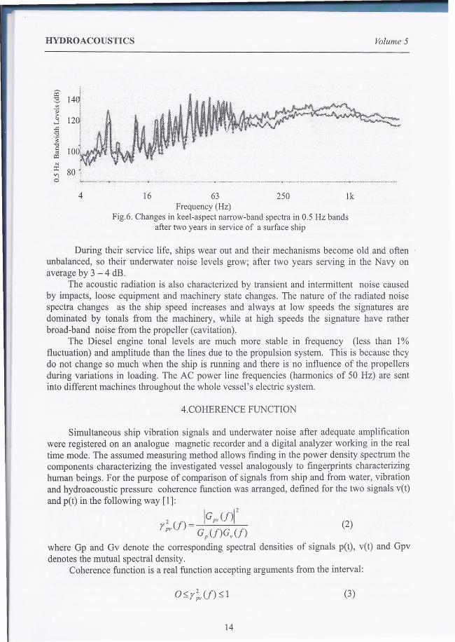
Fig.ó. Changes in keel-aspect narrow-band spectra in 0.5 Hz bandsafter two years in service of a surface ship
During their service life, ships wear out and their mechanisms become old and oftenunbalanced, so their underwater noise levels grow; after two years serving in the Navy onaverage by 3 - 4 dB.
The acoustic radiation is also characterized by transient and intermittent noise causedby impacts, loose equipment and machinery state changes. The nature of the radiated noisespectra changes as the ship speed increases and always at low speeds the signatures aredominated by ton ais from the machinery, while at high speeds the signature have ratherbroad-band noise from the propeller (cavitation).
The Diesel engine tonal levels are much more stable in frequency (less than 1%fluctuation) and amplitude than the lines due to the propulsion system. This is because theydo not change so much when the ship is running and there is no influence of the propellersduring variations in loading. The AC power line frequencies (harmonics of 50 Hz) are sentinto different machines throughout the whole vessel's electric system.
4.COHERENCE FUNCTION
Simultaneous ship vibration signals and underwater noise after adequate amplificationwere registered on an analogue magnetic recorder and a digital analyzer working in the realtime mode. The assumed measuring method allows finding in the power density spectrum thecomponents characterizing the investigated vessel analogously to fingerprints characterizinghuman beings. For the purpose of comparison of signals from ship and [rom water, vibrationand hydroacoustic pressure coherence function was arranged, defined for the two signais vet)and pet) in the following way [1]:
2 IGpv(ffr pv(f) = G p (f)G v (f) (2)
where Gp and Gv denote the corresponding spectral densities of signais pet), vet) and Gpvdenotes the mutual spectral density.
Coherence function is a real function accepting arguments from the interval:
(3)
14

Volume 5 HYDROACOUSTICS
Therefore, the zero value occurs for signaIs that do not have the cause association and the onevalue for signaIs coming from the same source. Using the dependence (1) we de termin e thecoherence function between the signals. The components in the coherence spectrumdetermined this way reflect qualitative correlations associated with particular frequenciescoming from a working piece of equipment.
5. RESULTS OF RANGE MEASUREMENTS FOR STATIONARY VESSELS.
The interpretation of the underwater noise of a vessel was conducted by analyzing thespectra of consecutively powered up machines and comparing them with the correspondingunderwater noise. In the first phase the measurements of vibration velocities and aggregatenoise (primary engines not working) were carried out. Then, the measurements werecontinued for the left, right and both main engines.
Frequency Hz Coherency function Vibration on thehull (urn/s)
16.5 0.8 1325 1 8037.5 0.8 6950 l 4262.5 0.9 8.4
75 1 7287.5 l 64100 0.8 23112.5 l 55125 1 28150 1 66162.5 1 35175 0.7 69200 0.9 19
Table 1. Vibration and coherence function ofhydroacoustic pressure and vibration.
The comparison of vibrations velocities registered at the ship's hull and at thefundament of the power generators with the underwater noise were presented in table 1.
Analogically, the research was conducted for the ship's main engine. The results ofnarrow-band spectrallevels and the coherence function were shown on figure 7.
25,37.5,50,62.5, 75,87.5, 100,112.5,125, 137.5, 150, ...
Frequency HarmonicsVibrationFormula Hz
Unbalancedparts
in = k.fo 25 50, 75,100, 125, 150, 175,200, ...
12.5Diesel firingrate
Table 2. Basic frequencies and harrnonics ofvibration.
15

HYDROACOUSTlCS Volume 5
140
':::~~H~HJ~'r ..~ 11 i . I f i r L I I tJ f I. f I ! I !
o ,<U",,,,,<,, ł """;~,,",Ji kL ,~~ L~4ó'" ·~Jłl··,~,.J6~1.~",··lL.AJ ····8'O~···",..j.'kl.,",.\tFrequency (Hz)
Fig.7. Narrow-band spectra and coherence function of underwater acoustic pressure andvibration of a stationarv ship
The dependence between the vibrations and their response (underwater noise) aredetennined by the energy transfer coefficient a. With the assumption that the vibrating hullgenerates a fiat wave, the relationship between the speed of vibration and the acousticpressure level is as follows:
where:
a = L1m,lllz
pcvLlm, 1Hz - the acoustic pressure level ref to l m and 1Hz, v - vibration speed (mis),
p - water density (kg/nr'), c - sound speed (mis)
(4)
L1m,IHZ= L + 20 log R - 10 log !:l f (5)
where: L - acoustic pressure level under ship (dB re f-lPa),R - the distance between a ship and a sensor (m),Sf - the width of an applied filter (Hz)
The results of the ac . l d ffi . hown in tab. 3.'b doustic eve s, VI ratton s oee s an coe icient a are sf (Hz) L (Pa) v (mis) a12.5 3.14 0.001 2.2 10-5
25 6.3 0.00032 lA 10.2
37.5 14.1 0.00028 3A lO-l
75 56.2 0.0005 7.7 lO-L
Table 3. The energy transmission coefficient ca1culated for consecutive frequencies.
REFERENCES
l. E. Kozaczka: Underwater ship noise. Symposium on Hydroacoustics, Gdańsk-Jurata2000.
2. P.T. Arveson, D. T. Vendittis: Radiated noise characteristics of a modem cargo ship. J.Acoust. Soc. Am., 107 (1),118-129,2000,
3. D. Ross: Mechanics ofUnderwater Noise, Pergamon, and New York 1976.4.R. J. Urick: Principles ofUnderwater Sound, Me Graw-Hill, New York 1975. Chap. 10.
16